US20130181645A1 - Drive system and method for operating such a drive system - Google Patents
Drive system and method for operating such a drive systemDownload PDFInfo
- Publication number
- US20130181645A1 US20130181645A1US13/551,135US201213551135AUS2013181645A1US 20130181645 A1US20130181645 A1US 20130181645A1US 201213551135 AUS201213551135 AUS 201213551135AUS 2013181645 A1US2013181645 A1US 2013181645A1
- Authority
- US
- United States
- Prior art keywords
- drive system
- thyristor
- monitor
- transistors
- inverter
- Prior art date
- Legal status (The legal status is an assumption and is not a legal conclusion. Google has not performed a legal analysis and makes no representation as to the accuracy of the status listed.)
- Granted
Links
- 238000000034methodMethods0.000titleclaimsdescription17
- 230000004913activationEffects0.000claimsdescription25
- 230000003213activating effectEffects0.000claimsdescription15
- 238000012360testing methodMethods0.000claimsdescription5
- 238000012544monitoring processMethods0.000claimsdescription4
- 230000007257malfunctionEffects0.000abstractdescription10
- 238000005259measurementMethods0.000description9
- 238000010586diagramMethods0.000description8
- 230000000875corresponding effectEffects0.000description6
- 238000011084recoveryMethods0.000description4
- 230000008901benefitEffects0.000description3
- 238000004590computer programMethods0.000description3
- 230000006378damageEffects0.000description3
- 230000004044responseEffects0.000description3
- 230000009849deactivationEffects0.000description2
- 238000002955isolationMethods0.000description2
- 238000012986modificationMethods0.000description2
- 230000004048modificationEffects0.000description2
- 230000008569processEffects0.000description2
- 230000001960triggered effectEffects0.000description2
- 230000003313weakening effectEffects0.000description2
- 230000007547defectEffects0.000description1
- 230000002950deficientEffects0.000description1
- 230000005347demagnetizationEffects0.000description1
- 230000008030eliminationEffects0.000description1
- 238000003379elimination reactionMethods0.000description1
- 238000012545processingMethods0.000description1
- 230000009467reductionEffects0.000description1
- 230000001360synchronised effectEffects0.000description1
- 238000004804windingMethods0.000description1
Images


Classifications
- H—ELECTRICITY
- H02—GENERATION; CONVERSION OR DISTRIBUTION OF ELECTRIC POWER
- H02P—CONTROL OR REGULATION OF ELECTRIC MOTORS, ELECTRIC GENERATORS OR DYNAMO-ELECTRIC CONVERTERS; CONTROLLING TRANSFORMERS, REACTORS OR CHOKE COILS
- H02P3/00—Arrangements for stopping or slowing electric motors, generators, or dynamo-electric converters
- H02P3/06—Arrangements for stopping or slowing electric motors, generators, or dynamo-electric converters for stopping or slowing an individual dynamo-electric motor or dynamo-electric converter
- H02P3/08—Arrangements for stopping or slowing electric motors, generators, or dynamo-electric converters for stopping or slowing an individual dynamo-electric motor or dynamo-electric converter for stopping or slowing a DC motor
- B—PERFORMING OPERATIONS; TRANSPORTING
- B60—VEHICLES IN GENERAL
- B60L—PROPULSION OF ELECTRICALLY-PROPELLED VEHICLES; SUPPLYING ELECTRIC POWER FOR AUXILIARY EQUIPMENT OF ELECTRICALLY-PROPELLED VEHICLES; ELECTRODYNAMIC BRAKE SYSTEMS FOR VEHICLES IN GENERAL; MAGNETIC SUSPENSION OR LEVITATION FOR VEHICLES; MONITORING OPERATING VARIABLES OF ELECTRICALLY-PROPELLED VEHICLES; ELECTRIC SAFETY DEVICES FOR ELECTRICALLY-PROPELLED VEHICLES
- B60L7/00—Electrodynamic brake systems for vehicles in general
- B60L7/10—Dynamic electric regenerative braking
- B60L7/14—Dynamic electric regenerative braking for vehicles propelled by AC motors
- B—PERFORMING OPERATIONS; TRANSPORTING
- B60—VEHICLES IN GENERAL
- B60L—PROPULSION OF ELECTRICALLY-PROPELLED VEHICLES; SUPPLYING ELECTRIC POWER FOR AUXILIARY EQUIPMENT OF ELECTRICALLY-PROPELLED VEHICLES; ELECTRODYNAMIC BRAKE SYSTEMS FOR VEHICLES IN GENERAL; MAGNETIC SUSPENSION OR LEVITATION FOR VEHICLES; MONITORING OPERATING VARIABLES OF ELECTRICALLY-PROPELLED VEHICLES; ELECTRIC SAFETY DEVICES FOR ELECTRICALLY-PROPELLED VEHICLES
- B60L3/00—Electric devices on electrically-propelled vehicles for safety purposes; Monitoring operating variables, e.g. speed, deceleration or energy consumption
- B60L3/0023—Detecting, eliminating, remedying or compensating for drive train abnormalities, e.g. failures within the drive train
- B60L3/0076—Detecting, eliminating, remedying or compensating for drive train abnormalities, e.g. failures within the drive train relating to braking
- B—PERFORMING OPERATIONS; TRANSPORTING
- B60—VEHICLES IN GENERAL
- B60L—PROPULSION OF ELECTRICALLY-PROPELLED VEHICLES; SUPPLYING ELECTRIC POWER FOR AUXILIARY EQUIPMENT OF ELECTRICALLY-PROPELLED VEHICLES; ELECTRODYNAMIC BRAKE SYSTEMS FOR VEHICLES IN GENERAL; MAGNETIC SUSPENSION OR LEVITATION FOR VEHICLES; MONITORING OPERATING VARIABLES OF ELECTRICALLY-PROPELLED VEHICLES; ELECTRIC SAFETY DEVICES FOR ELECTRICALLY-PROPELLED VEHICLES
- B60L50/00—Electric propulsion with power supplied within the vehicle
- B60L50/50—Electric propulsion with power supplied within the vehicle using propulsion power supplied by batteries or fuel cells
- B60L50/51—Electric propulsion with power supplied within the vehicle using propulsion power supplied by batteries or fuel cells characterised by AC-motors
- H—ELECTRICITY
- H02—GENERATION; CONVERSION OR DISTRIBUTION OF ELECTRIC POWER
- H02P—CONTROL OR REGULATION OF ELECTRIC MOTORS, ELECTRIC GENERATORS OR DYNAMO-ELECTRIC CONVERTERS; CONTROLLING TRANSFORMERS, REACTORS OR CHOKE COILS
- H02P3/00—Arrangements for stopping or slowing electric motors, generators, or dynamo-electric converters
- H02P3/06—Arrangements for stopping or slowing electric motors, generators, or dynamo-electric converters for stopping or slowing an individual dynamo-electric motor or dynamo-electric converter
- H02P3/18—Arrangements for stopping or slowing electric motors, generators, or dynamo-electric converters for stopping or slowing an individual dynamo-electric motor or dynamo-electric converter for stopping or slowing an AC motor
- H02P3/22—Arrangements for stopping or slowing electric motors, generators, or dynamo-electric converters for stopping or slowing an individual dynamo-electric motor or dynamo-electric converter for stopping or slowing an AC motor by short-circuit or resistive braking
- Y—GENERAL TAGGING OF NEW TECHNOLOGICAL DEVELOPMENTS; GENERAL TAGGING OF CROSS-SECTIONAL TECHNOLOGIES SPANNING OVER SEVERAL SECTIONS OF THE IPC; TECHNICAL SUBJECTS COVERED BY FORMER USPC CROSS-REFERENCE ART COLLECTIONS [XRACs] AND DIGESTS
- Y02—TECHNOLOGIES OR APPLICATIONS FOR MITIGATION OR ADAPTATION AGAINST CLIMATE CHANGE
- Y02T—CLIMATE CHANGE MITIGATION TECHNOLOGIES RELATED TO TRANSPORTATION
- Y02T10/00—Road transport of goods or passengers
- Y02T10/60—Other road transportation technologies with climate change mitigation effect
- Y02T10/64—Electric machine technologies in electromobility
- Y—GENERAL TAGGING OF NEW TECHNOLOGICAL DEVELOPMENTS; GENERAL TAGGING OF CROSS-SECTIONAL TECHNOLOGIES SPANNING OVER SEVERAL SECTIONS OF THE IPC; TECHNICAL SUBJECTS COVERED BY FORMER USPC CROSS-REFERENCE ART COLLECTIONS [XRACs] AND DIGESTS
- Y02—TECHNOLOGIES OR APPLICATIONS FOR MITIGATION OR ADAPTATION AGAINST CLIMATE CHANGE
- Y02T—CLIMATE CHANGE MITIGATION TECHNOLOGIES RELATED TO TRANSPORTATION
- Y02T10/00—Road transport of goods or passengers
- Y02T10/60—Other road transportation technologies with climate change mitigation effect
- Y02T10/70—Energy storage systems for electromobility, e.g. batteries
Definitions
- the present inventionrelates to a drive system and a method for operating such a drive system, in particular for an electric vehicle.
- An electric vehicleis driven by way of a battery carried by said vehicle, a drive regulator, an inverter and an electric motor—hereafter referred to simply as a motor.
- the drive systemhere contains at least the drive regulator and the inverter. If a battery and motor are connected, these are also part of the drive system.
- the motorhere is in particular a permanently excited synchronous motor. Such motors have a high level of efficiency and a high power density.
- a specific speed to torque characteristicmeans that such a motor is also operated in the field weakening range. To this end a corresponding current is impressed on the motor. This current generates a magnetic field, which counteracts the field generated by the permanent magnets.
- the field weakening currentcan no longer be maintained in the event of a malfunction.
- impermissible torquesspecifically braking torques, and impermissible stresses can then be produced and these then have to be controlled.
- armature short circuit brakingTo decelerate an electric motor what is known as armature short circuit braking is known per se. Such deceleration is preferably considered when the motor can no longer be braked electrically (in any other manner), as the short circuit brought about produces a temporarily high current flow.
- armature short circuit brakingor in short with an armature short circuit—in the event of a malfunction, the three upper or three lower transistors (IGBTs) of the inverter are activated.
- the stator windings of the motorare short circuited in the process so that current can flow between them.
- the rotoris thus brought to a standstill.
- a braking torquehereby results over the entire speed range, which is still acceptable with typical motor designs.
- the transistorscan no longer be activated for an armature short circuit and on the other hand the freewheeling diodes are no longer conducting, a very high voltage occurs, also as a further exceptional situation, at the motor connectors or at the output of the inverter. This can cause the destruction of the inverter and/or of the motor as well as arcing with fire as a result and can eliminate the safe electrical isolation of inverter and motor.
- a drive system for an electric motorincludes a connection for a battery, and an inverter having an input side connected to an intermediate circuit and an output side having a connection for an electric motor.
- the intermediate circuitincludes a first thyristor connected in parallel with an intermediate circuit capacitance and configured to be activated by a monitor incorporated in or assigned to the drive system.
- a drive system for an electric motorincludes a connection for a battery, an inverter having an input side connected to an intermediate circuit and an output side having a connection for an electric motor, a rectifier having an input side connected at the output side of the inverter in parallel with the electric motor, and a thyristor connected an output side of the rectifier and configured to be activated by a monitor incorporated in or assigned to the drive system.
- the rectifier and the second thyristormay be used alone or on conjunction with the first transistor.
- a method for testing the aforedescribed drive systemincludes the steps of isolating the inverter electrically from the battery, activating the first thyristor, and comparing with the monitor a resulting intermediate circuit current with an expected intermediate circuit current.
- a method for testing the aforedescribed drive systemincludes the steps of, with the monitor, activating the thyristor, activating the inverter to output successive short voltage pulses, and monitoring during or after each voltage pulse whether the respective voltage pulse produces a current flow.
- the thyristor provided in the intermediate circuitis hereafter referred to as the first thyristor and the thyristor provided on the output side of the rectifier is referred to as the second thyristor.
- the descriptionalso relates to a drive system, which does not comprise a first thyristor but only the rectifier and the second thyristor or only comprises the first thyristor and no rectifier and second thyristor.
- the advantage of the inventionis that with the first thyristor in the intermediate circuit a situation can be controlled in which an undesirable recovery current into the battery results.
- the first thyristorcan be activated, causing upon its so-called ignition an armature short circuit in the intermediate circuit by way of the conventional freewheeling diodes contained in the inverter.
- overvoltages at the output of the invertermay advantageously be controlled with the rectifier and the second thyristor. Such an overvoltage at the output of the inverter can result if the freewheeling diodes of the inverter no longer conduct or if its transistors can no longer be switched.
- Connected to terminals provided to connect the motor or—electrically identically or at least essentially identically—to the output terminals of the inverter, in other words parallel to a motor connected to the drive control unit, as inverter,are or will be an in particular six-pulse rectifier and by way of its output side the second thyristor. Upon activation of the second thyristor an armature short circuit is generated across the diodes of the rectifier.
- the drive systemmay include a fuse electrically connected between the battery and the intermediate circuit, with the fuse and the first thyristor being connected in series to the battery as the power source on activation of the first thyristor in respect of a current circuit closed across the first thyristor, a short circuit current flows from the battery by way of the fuse and the first thyristor, triggering the fuse within the shortest time and thus isolating the inverter along with the intermediate circuit electrically from the battery.
- This electrical isolationalso protects the first thyristor from destruction by the short circuit current.
- the first or second thyristoris triggered by the monitor, if a certain exceptional situation exists, which is to be controlled by activation of the respective thyristor.
- the monitorcompares continuously or regularly, preferably at intervals of equal length, whether the intermediate circuit voltage U_ZK or a measure of the intermediate circuit voltage exceeds a predetermined or predeterminable threshold value.
- the monitorincludes the functionality of a comparator (either in hardware, firmware or software) and means for supplying the measure of the intermediate circuit voltage U_ZK and of the threshold value to the comparator as well as means for forwarding and outputting a signal depending on the result of the comparison performed by the comparator.
- the monitoruses the measured currents and voltages to calculate the torque and compares this with the setpoint value. If the deviation exceeds a lower or upper threshold, ignition of the thyristor is similarly performed. A corresponding method is provided for activation of the second thyristor and here the monitor compares—as described above—whether the measure of an output voltage of the inverter exceeds a predetermined or predeterminable threshold value.
- the monitorwhen in addition to activating the first thyristor or in addition to activating the second thyristor, in particular after the passage of a predetermined or predeterminable waiting period, activates either the three lower transistors of the inverter or the three upper transistors of the inverter or the lower and upper transistors together, an armature short circuit brought about in this manner causes the previously ignited thyristor to be extinguished again.
- the thyristors and the transistorsit may be necessary to ensure, for example by means of a diode connected in series to the thyristor, that the current in the thyristors drops below the holding current, when the transistors are activated.
- a possible criterion for subsequent termination of the activation of the transistors of the inverteris that the monitor monitors when a measure of a speed of the electric motor drops below a predetermined or predeterminable threshold value.
- the monitormay use software, firmware or hardware comparator provided for the purpose to generate an electrical signal to terminate activation of the transistors of the inverter, thereby also in turn terminating the armature short circuit.
- control facilityfor monitoring the drive system and for activating power components contained therein, specifically transistors and/or thyristors, which operates according to a method as described here and in the following and comprises means for performing the method for this purpose.
- the inventionis preferably implemented in the form of software or firmware or a combination of software and firmware.
- the method according to the inventionmay be implemented with a computer program having program code instructions that can be executed by a computer, specifically for example a processing unit of the monitor in the manner of a microprocessor or ASIC, and with a storage medium containing such a computer program and finally also a control facility or a drive system having a memory into which such a computer program is or can be loaded as a means for performing the method and its embodiments.
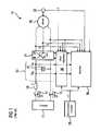
- FIG. 1shows a drive system according to the prior art
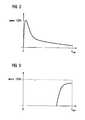
- FIGS. 2 and 3show diagrams of a torque pattern in certain error/exceptional situations
- FIG. 4shows a drive system according to the present invention
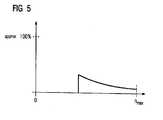
- FIG. 5shows a torque pattern that can be achieved with the drive system according to FIG. 4 .
- the drive system 10includes a battery 12 , in particular a high-voltage battery, which is connected by way of a first and second switch 14 , 16 and a fuse 18 to an intermediate circuit 20 with an intermediate circuit capacitance 22 .
- a battery 12in particular a high-voltage battery
- an inverter 24also referred to as an IGBT module
- a motor 26is connected to this in a three-phase manner.
- a drive control module 28which generates a setpoint torque value (m*) and forwards it at least to a drive regulator 30 as the setpoint value for a regulation implemented there.
- the setpoint torque valuecan be formed or derived indirectly or directly by the drive control module 28 , for example based on a position of a pedal (gas pedal).
- the drive regulator 30evaluates measurement values for the regulation process, specifically measurement values for an intermediate circuit voltage U_ZK, an intermediate circuit current I_ZK and the phase currents i_R, i_S, i_T to the motor 26 . It is optionally also possible to detect an instantaneous speed n of the motor 26 by way of an encoder 32 , so that in some instances this is also available as a further measurement value.
- the drive regulatoruses the predetermined setpoint torque value m* and the instantaneous values of individual or all measurement values to control the inverter 24 , specifically one or more transistors 36 contained therein and each connected in a parallel manner to a freewheeling diode 34 .
- An in particular safety-oriented torque monitor 38is used for the known protection measures proposed in the introduction to the description, also being referred to in the following in some instances in a shorter manner simply as a monitor 38 .
- Activation of the inverter 24specifically of the three lower and/or upper transistors 36 , can bring about the armature short circuit described in the introduction to the description for example.
- FIG. 2shows the torque/braking torque resulting with an armature short circuit plotted over speed. It can be seen that a braking torque results from a maximum speed n_max over the entire speed range and this rises in the direction of low speeds and reaches a maximum shortly before the motor 26 comes to a standstill (zero speed).
- FIG. 3shows a representation of the braking torque over speed for recovery into the battery 12 as described above. At high speeds, in particular also at maximum speed n_max, a high braking torque is present, disappearing in the direction of lower speeds. The 100% in both diagrams ( FIG. 2 and FIG. 3 ) refers to the maximum torque.
- FIG. 4shows a drive system 10 based on the drive system 10 already shown in FIG. 1 , for which reference should be made to the descriptions there, having torque reduction and voltage limiting means, which are activated in each instance in the event of a malfunction.
- the monitor 38From the system variables of the drive system 10 , specifically the measurement values already described in conjunction with the description of the diagram in FIG. 1 , as well as additional measurement values in respect of the respective voltages u_R, u_S, u_T between the three phases supplying the motor 26 , a measurement value for a current speed n and/or a motor position and any measurement values for a current torque, it is possible for the monitor 38 to monitor the condition of the drive system 10 , in particular the respective torque.
- the actuators provided for this purposeare primarily the inverter 24 contained in the system 10 anyway (see FIG. 1 ) and then as additional components of the system 10 a first electronic switch, in particular a thyristor—first thyristor 40 —as well as a rectifier 42 and a second electronic switch, in particular a thyristor—second thyristor 44 .
- the first thyristor 40is required to prevent unwanted recovery into the battery 12 .
- the rectifier 42 and the second thyristor 44are required to manage an overvoltage at the output of the inverter 24 .
- a drive system 10which includes both the first thyristor 40 and also the rectifier 42 and the second thyristor 44 , can control both exceptional situations. However in principle a drive system 10 is also possible, in which control of one of the two exceptional situations mentioned above is sufficient or a priority. To this extent the first thyristor 40 on the one hand and also the rectifier 42 and the second thyristor 44 on the other hand as well as a corresponding interpretation of the monitor 38 for their activation should be seen as optional, alternative components of the drive system 10 .
- a drive system 10which includes both the first thyristor 40 and also the rectifier 42 and the second thyristor 44 .
- the first and second thyristor 40 , 44can in principle also be replaced by a transistor.
- the descriptioncontinues on the basis of thyristors 40 , 44 as a respective switching element, with the term “thyristor” referring to a “thyristor or transistor” in each instance.
- the first thyristor 40is activated (ignited) by the monitor 38 when an overvoltage is detected in the intermediate circuit 20 or at the input of the inverter 24 , if such an intermediate circuit voltage U_ZK or a measure of the intermediate circuit voltage that can be processed by the monitor 38 exceeds a predetermined or predeterminable threshold value. Due to the activation of the first thyristor 40 an armature short circuit results in the intermediate circuit 20 across the freewheeling diodes 34 of the inverter 24 . In one embodiment of the drive system 10 the fuse 18 shown in FIG. 1 and FIG. 4 can be switched into the supply line from the battery 12 .
- the monitor 38can also activate its three lower or its three upper transistors 36 or all the transistors 36 . On activation of either the lower or upper transistors 36 just one additional electrical path results for the armature short circuit. Upon activation of all the transistors 36 , two additional, redundant electrical paths result for the armature short circuit.
- the first thyristor 40is extinguished again (in other words deactivated) (holding voltage is higher than forward voltage of transistors 36 ; in some instances an additional diode VI shown in the diagram in FIG. 4 is required in series with the first thyristor 40 ).
- the armature short circuitis then maintained across the transistors 36 of the inverter 24 .
- the monitor 38can deactivate the transistors 36 again. This terminates the armature short circuit and the otherwise high braking torque in the lower speed range can be reduced to zero, as shown in the diagram in FIG. 5 in an identical coordination system to the ones in the diagrams in FIG. 2 and FIG. 3 .
- the second thyristor 44is also activated (ignited) by the monitor 38 in the event of certain errors or exceptional situations when an overvoltage is detected at one of the outputs of the inverter 24 , if such an output voltage or a measure of the inverter output voltage that can be processed by the monitor 38 exceeds a predetermined or predeterminable threshold value.
- Activation of the second thyristor 44produces an armature short circuit across the transistors of the rectifier 42 , which is embodied as a six-pulse rectifier based on the three-phase connector.
- the rectifier 42is connected on the output side of the inverter 24 to motor terminals provided there. In the case of a motor 26 connected to the drive system 10 therefore the motor 26 and rectifier 42 are connected in parallel manner to the output of the inverter 24 .
- the second thyristor 44is connected on an output side, in other words the direct current side, of the rectifier 42 to its output terminals.
- the ignition of the second thyristor 44 brought about or to be brought about by the monitor 38 in the respective exceptional situationbrings about the armature short circuit and at the same time a short circuit of the voltage between inverter 24 and motor 26 .
- the thyristorcan be extinguished again by activating the lower or upper transistors.
- the monitor 38can then terminate the armature short circuit again, as soon as the speed of the motor 26 drops below a predetermined or determinable speed, in other words as soon as the speed or a measure of such a speed drops below a predetermined or predeterminable threshold value. In this manner the otherwise high braking torque is reduced to zero in the lower speed range ( FIG. 5 ), as described above for the input side fuse.
- the inverter 24is preferably isolated electrically from the battery 12 .
- the switches 14 , 16are able to do this as electrically or electronically activatable switches, for example as relays.
- the activation of a switch 14 , 16 or both switches 14 , 16is performed indirectly or directly by the monitor 38 , in response to the respectively established exceptional situation, in other words for example in response to an overvoltage on the output side of the inverter 24 . Because the switch or each switch 14 , 16 does not have to be opened when subject to current loading, no particular wear results.
- the reliability of the drive system 10can be further increased, if so-called dormant errors are also revealed by so-called forced dynamization, in other words intentional triggering of individual power components.
- One possibility hereis for the first thyristor 40 to be checked by always opening the two switches 14 , 16 after stopping the electric vehicle, in other words isolating the inverter 24 electrically from the battery 12 , and then activating the first thyristor 40 .
- the intermediate circuit capacitance 22is then discharged across the first thyristor 40 and the expected current flow in the intermediate circuit 20 is the discharge current of the intermediate circuit capacitance 22 .
- One possible way of testing the rectifier 42 and the second thyristor 44is for the inverter 24 to output short voltage pulses one after the other in all six switching combinations while being monitored by the monitor 38 with the vehicle stationary and for the second thyristor 44 to be ignited at the same time. Because the monitor 38 checks by evaluating corresponding measurement values whether a current i_R, i_S, i_T is flowing, all six diodes in the rectifier 42 and the second thyristor 44 can be tested. The voltage pulses here have to be so short that the resulting current is not too high. In some instances a diode V 2 shown in the diagram in FIG.
- the voltage pulsescan be transferred to the motor before ignition of the thyristor in each instance.
- the thyristoris only ignited after the transistors have been blocked at the end of the respective voltage pulse.
- the decay time of the currentis much longer with a successfully ignited thyristor than with a non-conducting thyristor or defective diodes. All the diodes of the rectifier and the thyristor can be tested thus.
- a first thyristor 40 in the intermediate circuit 20 and/or a second thyristor 44 and a rectifier 42 on the output side of the inverter 24is/are used in addition to the inverter 24 .
- These additional actuators 40 , 42 , 44 and the inverter 24are activated by way of an in particular safety-oriented torque monitor (monitor 38 ).
- actuator 24 , 40 , 42 , 44 or which switching elements 36 contained therein are activatedis derived from system variables such as current (IZK, i_R, i_S, i_T), voltage (U_ZK, u_R, u_S, u_T) and/or position or speed (m) of the motor 26 , etc.
- system variablessuch as current (IZK, i_R, i_S, i_T), voltage (U_ZK, u_R, u_S, u_T) and/or position or speed (m) of the motor 26 , etc.
- IZK, i_R, i_S, i_Tcurrent
- U_ZKvoltage
- u_Ru_R
- u_Su_S
- u_Tposition or speed
- the inverter 24can be isolated electrically from the battery 12 at least on the input side and in the embodiment with the first thyristor 40 on the one hand and the rectifier 42 and the second thyristor 44 on the other hand it can be isolated electrically on both sides from the energy suppliers (battery 12 , motor 26 ) in a contactless manner.
- switches 14 , 16that are normally required anyway can be included in the safety concept and the safety-related power components 40 , 42 , 44 can be checked for functional capacity by means of specific switching positions and activation methods brought about by the monitor 38 .
Landscapes
- Engineering & Computer Science (AREA)
- Power Engineering (AREA)
- Transportation (AREA)
- Mechanical Engineering (AREA)
- Life Sciences & Earth Sciences (AREA)
- Sustainable Development (AREA)
- Sustainable Energy (AREA)
- Electric Propulsion And Braking For Vehicles (AREA)
- Inverter Devices (AREA)
- Control Of Ac Motors In General (AREA)
- Control Of Electric Motors In General (AREA)
- Stopping Of Electric Motors (AREA)
Abstract
Description
- This application claims the priority of European Patent Application EP11174344, filed Jul. 18, 2011, pursuant to 35 U.S.C. 119(a)-(d), the content of which is incorporated herein by reference in its entirety as if fully set forth herein.
- The present invention relates to a drive system and a method for operating such a drive system, in particular for an electric vehicle.
- The following discussion of related art is provided to assist the reader in understanding the advantages of the invention, and is not to be construed as an admission that this related art is prior art to this invention.
- An electric vehicle is driven by way of a battery carried by said vehicle, a drive regulator, an inverter and an electric motor—hereafter referred to simply as a motor. The drive system here contains at least the drive regulator and the inverter. If a battery and motor are connected, these are also part of the drive system. The motor here is in particular a permanently excited synchronous motor. Such motors have a high level of efficiency and a high power density. A specific speed to torque characteristic means that such a motor is also operated in the field weakening range. To this end a corresponding current is impressed on the motor. This current generates a magnetic field, which counteracts the field generated by the permanent magnets.
- However, the field weakening current can no longer be maintained in the event of a malfunction. Depending on the type of malfunction, impermissible torques, specifically braking torques, and impermissible stresses can then be produced and these then have to be controlled.
- In industrial drives a braking torque is not normally a problem in the event of a malfunction, as the best possible fast deceleration is always desirable.
- To decelerate an electric motor what is known as armature short circuit braking is known per se. Such deceleration is preferably considered when the motor can no longer be braked electrically (in any other manner), as the short circuit brought about produces a temporarily high current flow. With armature short circuit braking—or in short with an armature short circuit—in the event of a malfunction, the three upper or three lower transistors (IGBTs) of the inverter are activated. The stator windings of the motor are short circuited in the process so that current can flow between them. The rotor is thus brought to a standstill. A braking torque hereby results over the entire speed range, which is still acceptable with typical motor designs.
- However the probability that an IGBT module or an activation circuit provided for its activation will fail in such a manner that an armature short circuit is no longer possible is relatively high or at least so high that it is not possible to meet safety requirements in this manner.
- In the event of a defect in an IGBT module it is essential to start with all conceivable malfunctions in respect of the transistors and freewheeling diodes contained in the modules.
- If for example neither the lower nor the upper transistors can be activated, the problem arises that normally the electromotive force (EMF) of the motor would increase by certain factors in relation to the nominal voltage at high speeds after elimination of the demagnetization current and with the motor connectors open. This is prevented by clamping the stator voltage across the freewheeling diodes to the battery voltage but this produces the exceptional situation of a high recovery current into the battery, generating a high, impermissible braking torque. Once the speed has dropped so low that the rectified EMF is lower than the battery voltage, the braking torque becomes zero.
- If on the one hand the transistors can no longer be activated for an armature short circuit and on the other hand the freewheeling diodes are no longer conducting, a very high voltage occurs, also as a further exceptional situation, at the motor connectors or at the output of the inverter. This can cause the destruction of the inverter and/or of the motor as well as arcing with fire as a result and can eliminate the safe electrical isolation of inverter and motor.
- It would therefore be desirable and advantageous to obviate prior art shortcomings and to provide an improved method and/or an apparatus for operating a drive system, with which the abovementioned errors can be controlled with adequate reliability, and more particularly a method and/or an apparatus suitable for use in or with electric vehicles.
- According to one aspect of the present invention, a drive system for an electric motor includes a connection for a battery, and an inverter having an input side connected to an intermediate circuit and an output side having a connection for an electric motor. The intermediate circuit includes a first thyristor connected in parallel with an intermediate circuit capacitance and configured to be activated by a monitor incorporated in or assigned to the drive system.
- According to another aspect of the invention, a drive system for an electric motor includes a connection for a battery, an inverter having an input side connected to an intermediate circuit and an output side having a connection for an electric motor, a rectifier having an input side connected at the output side of the inverter in parallel with the electric motor, and a thyristor connected an output side of the rectifier and configured to be activated by a monitor incorporated in or assigned to the drive system. The rectifier and the second thyristor may be used alone or on conjunction with the first transistor.
- According to yet another aspect of the invention, a method for testing the aforedescribed drive system includes the steps of isolating the inverter electrically from the battery, activating the first thyristor, and comparing with the monitor a resulting intermediate circuit current with an expected intermediate circuit current.
- According to yet another aspect of the invention, a method for testing the aforedescribed drive system includes the steps of, with the monitor, activating the thyristor, activating the inverter to output successive short voltage pulses, and monitoring during or after each voltage pulse whether the respective voltage pulse produces a current flow.
- To make a distinction the thyristor provided in the intermediate circuit is hereafter referred to as the first thyristor and the thyristor provided on the output side of the rectifier is referred to as the second thyristor. Since the drive system can be extended alternatively or cumulatively by the first thyristor on the one hand and the rectifier and the second thyristor on the other hand, the description also relates to a drive system, which does not comprise a first thyristor but only the rectifier and the second thyristor or only comprises the first thyristor and no rectifier and second thyristor.
- The advantage of the invention is that with the first thyristor in the intermediate circuit a situation can be controlled in which an undesirable recovery current into the battery results. The first thyristor can be activated, causing upon its so-called ignition an armature short circuit in the intermediate circuit by way of the conventional freewheeling diodes contained in the inverter.
- Alternatively or in addition, overvoltages at the output of the inverter may advantageously be controlled with the rectifier and the second thyristor. Such an overvoltage at the output of the inverter can result if the freewheeling diodes of the inverter no longer conduct or if its transistors can no longer be switched. Connected to terminals provided to connect the motor or—electrically identically or at least essentially identically—to the output terminals of the inverter, in other words parallel to a motor connected to the drive control unit, as inverter, are or will be an in particular six-pulse rectifier and by way of its output side the second thyristor. Upon activation of the second thyristor an armature short circuit is generated across the diodes of the rectifier.
- According to an advantageous feature of the present invention, the drive system may include a fuse electrically connected between the battery and the intermediate circuit, with the fuse and the first thyristor being connected in series to the battery as the power source on activation of the first thyristor in respect of a current circuit closed across the first thyristor, a short circuit current flows from the battery by way of the fuse and the first thyristor, triggering the fuse within the shortest time and thus isolating the inverter along with the intermediate circuit electrically from the battery. This electrical isolation also protects the first thyristor from destruction by the short circuit current.
- The first or second thyristor, respectively, is triggered by the monitor, if a certain exceptional situation exists, which is to be controlled by activation of the respective thyristor. To activate the first thyristor, the monitor compares continuously or regularly, preferably at intervals of equal length, whether the intermediate circuit voltage U_ZK or a measure of the intermediate circuit voltage exceeds a predetermined or predeterminable threshold value. For this purpose the monitor includes the functionality of a comparator (either in hardware, firmware or software) and means for supplying the measure of the intermediate circuit voltage U_ZK and of the threshold value to the comparator as well as means for forwarding and outputting a signal depending on the result of the comparison performed by the comparator.
- Additionally or alternatively, the monitor uses the measured currents and voltages to calculate the torque and compares this with the setpoint value. If the deviation exceeds a lower or upper threshold, ignition of the thyristor is similarly performed. A corresponding method is provided for activation of the second thyristor and here the monitor compares—as described above—whether the measure of an output voltage of the inverter exceeds a predetermined or predeterminable threshold value.
- According to an advantageous feature of the present invention, when in addition to activating the first thyristor or in addition to activating the second thyristor, in particular after the passage of a predetermined or predeterminable waiting period, the monitor activates either the three lower transistors of the inverter or the three upper transistors of the inverter or the lower and upper transistors together, an armature short circuit brought about in this manner causes the previously ignited thyristor to be extinguished again. Depending on the forward characteristic of the thyristors and the transistors it may be necessary to ensure, for example by means of a diode connected in series to the thyristor, that the current in the thyristors drops below the holding current, when the transistors are activated.
- According to an advantageous feature of the present invention, a possible criterion for subsequent termination of the activation of the transistors of the inverter is that the monitor monitors when a measure of a speed of the electric motor drops below a predetermined or predeterminable threshold value. The monitor may use software, firmware or hardware comparator provided for the purpose to generate an electrical signal to terminate activation of the transistors of the inverter, thereby also in turn terminating the armature short circuit.
- The abovementioned object is also attained with a control facility, referred to here and in the following as a monitor, for monitoring the drive system and for activating power components contained therein, specifically transistors and/or thyristors, which operates according to a method as described here and in the following and comprises means for performing the method for this purpose. As far as this aspect is concerned, the invention is preferably implemented in the form of software or firmware or a combination of software and firmware. The method according to the invention may be implemented with a computer program having program code instructions that can be executed by a computer, specifically for example a processing unit of the monitor in the manner of a microprocessor or ASIC, and with a storage medium containing such a computer program and finally also a control facility or a drive system having a memory into which such a computer program is or can be loaded as a means for performing the method and its embodiments.
- Other features and advantages of the present invention will be more readily apparent upon reading the following description of currently preferred exemplified embodiments of the invention with reference to the accompanying drawing, in which:
FIG. 1 shows a drive system according to the prior art,FIGS. 2 and 3 show diagrams of a torque pattern in certain error/exceptional situations,FIG. 4 shows a drive system according to the present invention, andFIG. 5 shows a torque pattern that can be achieved with the drive system according toFIG. 4 .- Throughout all the figures, same or corresponding elements may generally be indicated by same reference numerals. These depicted embodiments are to be understood as illustrative of the invention and not as limiting in any way. It should also be understood that the figures are not necessarily to scale and that the embodiments are sometimes illustrated by graphic symbols, phantom lines, diagrammatic representations and fragmentary views. In certain instances, details which are not necessary for an understanding of the present invention or which render other details difficult to perceive may have been omitted.
- Turning now to the drawing, and in particular to
FIG. 1 , there is shown a simplified schematic diagram adrive system 10 for an electric vehicle (not shown). Thedrive system 10 includes abattery 12, in particular a high-voltage battery, which is connected by way of a first andsecond switch fuse 18 to anintermediate circuit 20 with anintermediate circuit capacitance 22. Following theintermediate circuit 20 here and in the following is aninverter 24, also referred to as an IGBT module, and connected to this in a three-phase manner is a motor (electric motor)26. - Provided for drive control purposes is a
drive control module 28, which generates a setpoint torque value (m*) and forwards it at least to adrive regulator 30 as the setpoint value for a regulation implemented there. The setpoint torque value can be formed or derived indirectly or directly by thedrive control module 28, for example based on a position of a pedal (gas pedal). - The
drive regulator 30 evaluates measurement values for the regulation process, specifically measurement values for an intermediate circuit voltage U_ZK, an intermediate circuit current I_ZK and the phase currents i_R, i_S, i_T to themotor 26. It is optionally also possible to detect an instantaneous speed n of themotor 26 by way of anencoder 32, so that in some instances this is also available as a further measurement value. The drive regulator uses the predetermined setpoint torque value m* and the instantaneous values of individual or all measurement values to control theinverter 24, specifically one ormore transistors 36 contained therein and each connected in a parallel manner to a freewheelingdiode 34. - An in particular safety-oriented
torque monitor 38 is used for the known protection measures proposed in the introduction to the description, also being referred to in the following in some instances in a shorter manner simply as amonitor 38. Activation of theinverter 24, specifically of the three lower and/orupper transistors 36, can bring about the armature short circuit described in the introduction to the description for example. - To this end
FIG. 2 shows the torque/braking torque resulting with an armature short circuit plotted over speed. It can be seen that a braking torque results from a maximum speed n_max over the entire speed range and this rises in the direction of low speeds and reaches a maximum shortly before themotor 26 comes to a standstill (zero speed).FIG. 3 shows a representation of the braking torque over speed for recovery into thebattery 12 as described above. At high speeds, in particular also at maximum speed n_max, a high braking torque is present, disappearing in the direction of lower speeds. The 100% in both diagrams (FIG. 2 andFIG. 3 ) refers to the maximum torque. FIG. 4 shows adrive system 10 based on thedrive system 10 already shown inFIG. 1 , for which reference should be made to the descriptions there, having torque reduction and voltage limiting means, which are activated in each instance in the event of a malfunction.- From the system variables of the
drive system 10, specifically the measurement values already described in conjunction with the description of the diagram inFIG. 1 , as well as additional measurement values in respect of the respective voltages u_R, u_S, u_T between the three phases supplying themotor 26, a measurement value for a current speed n and/or a motor position and any measurement values for a current torque, it is possible for themonitor 38 to monitor the condition of thedrive system 10, in particular the respective torque. - Depending on the malfunction or condition of the
system 10 corresponding actions are triggered by themonitor 38 as the control facility. The actuators provided for this purpose are primarily theinverter 24 contained in thesystem 10 anyway (seeFIG. 1 ) and then as additional components of the system10 a first electronic switch, in particular a thyristor—first thyristor 40—as well as arectifier 42 and a second electronic switch, in particular a thyristor—second thyristor 44. - The
first thyristor 40 is required to prevent unwanted recovery into thebattery 12. Therectifier 42 and thesecond thyristor 44 are required to manage an overvoltage at the output of theinverter 24. Adrive system 10, which includes both thefirst thyristor 40 and also therectifier 42 and thesecond thyristor 44, can control both exceptional situations. However in principle adrive system 10 is also possible, in which control of one of the two exceptional situations mentioned above is sufficient or a priority. To this extent thefirst thyristor 40 on the one hand and also therectifier 42 and thesecond thyristor 44 on the other hand as well as a corresponding interpretation of themonitor 38 for their activation should be seen as optional, alternative components of thedrive system 10. The description continues in the following for adrive system 10, which includes both thefirst thyristor 40 and also therectifier 42 and thesecond thyristor 44. The first andsecond thyristor transistors 36 of theinverter 24, the description continues on the basis ofthyristors - With certain errors or exceptional situations the
first thyristor 40 is activated (ignited) by themonitor 38 when an overvoltage is detected in theintermediate circuit 20 or at the input of theinverter 24, if such an intermediate circuit voltage U_ZK or a measure of the intermediate circuit voltage that can be processed by themonitor 38 exceeds a predetermined or predeterminable threshold value. Due to the activation of thefirst thyristor 40 an armature short circuit results in theintermediate circuit 20 across the freewheelingdiodes 34 of theinverter 24. In one embodiment of thedrive system 10 thefuse 18 shown inFIG. 1 andFIG. 4 can be switched into the supply line from thebattery 12. With such afuse 18 it is possible to isolate theinverter 24 electrically from thebattery 12 by tripping the fuse, due to the short circuit current flowing from thebattery 12 when thefirst thyristor 40 is activated. This for example prevents the destruction of thefirst thyristor 40 by the short circuit current from thebattery 12. - If the
inverter 24 is still functional in the respective exceptional situation, themonitor 38 can also activate its three lower or its threeupper transistors 36 or all thetransistors 36. On activation of either the lower orupper transistors 36 just one additional electrical path results for the armature short circuit. Upon activation of all thetransistors 36, two additional, redundant electrical paths result for the armature short circuit. - It is advantageous here that with the armature short circuit across the
inverter 24 thefirst thyristor 40 is extinguished again (in other words deactivated) (holding voltage is higher than forward voltage oftransistors 36; in some instances an additional diode VI shown in the diagram inFIG. 4 is required in series with the first thyristor40). The armature short circuit is then maintained across thetransistors 36 of theinverter 24. As soon as the speed of themotor 26 drops below a predetermined or predeterminable speed, in other words as soon as the speed or a measure of such a speed drops below a predetermined or predeterminable threshold value, themonitor 38 can deactivate thetransistors 36 again. This terminates the armature short circuit and the otherwise high braking torque in the lower speed range can be reduced to zero, as shown in the diagram inFIG. 5 in an identical coordination system to the ones in the diagrams inFIG. 2 andFIG. 3 . - The
second thyristor 44 is also activated (ignited) by themonitor 38 in the event of certain errors or exceptional situations when an overvoltage is detected at one of the outputs of theinverter 24, if such an output voltage or a measure of the inverter output voltage that can be processed by themonitor 38 exceeds a predetermined or predeterminable threshold value. - Activation of the
second thyristor 44 produces an armature short circuit across the transistors of therectifier 42, which is embodied as a six-pulse rectifier based on the three-phase connector. Therectifier 42 is connected on the output side of theinverter 24 to motor terminals provided there. In the case of amotor 26 connected to thedrive system 10 therefore themotor 26 andrectifier 42 are connected in parallel manner to the output of theinverter 24. Thesecond thyristor 44 is connected on an output side, in other words the direct current side, of therectifier 42 to its output terminals. The ignition of thesecond thyristor 44 brought about or to be brought about by themonitor 38 in the respective exceptional situation brings about the armature short circuit and at the same time a short circuit of the voltage betweeninverter 24 andmotor 26. - This reliably avoids both a dangerously high voltage and also a dangerously high torque at high speed. The method illustrated below, in which the transistors are also switched, only serves to improve the response. Safety is ensured even if the transistors can no longer be switched. This also means that faults in the relatively complicated control logic for the transistors do not cause safety to be put at risk.
- On or shortly before activation of the
second thyristor 44, an attempt should be made to deactivate the stillswitchable transistors 36 of theinverter 24, to prevent an unnecessary current flow. In an embodiment of thetransistors 36 with activation drivers with monitoring of the respective collector-emitter voltage (U_CE), automatic deactivation of the current-carrying, stillswitchable transistors 36 takes place as soon as the thyristor conducts. - When the lower or
upper transistors 36 can be activated again, the thyristor can be extinguished again by activating the lower or upper transistors. Themonitor 38 can then terminate the armature short circuit again, as soon as the speed of themotor 26 drops below a predetermined or determinable speed, in other words as soon as the speed or a measure of such a speed drops below a predetermined or predeterminable threshold value. In this manner the otherwise high braking torque is reduced to zero in the lower speed range (FIG. 5 ), as described above for the input side fuse. Before deactivation of thetransistors 36, in other words before termination of the armature short circuit, theinverter 24 is preferably isolated electrically from thebattery 12. In one embodiment theswitches switch switches monitor 38, in response to the respectively established exceptional situation, in other words for example in response to an overvoltage on the output side of theinverter 24. Because the switch or eachswitch - The reliability of the
drive system 10 can be further increased, if so-called dormant errors are also revealed by so-called forced dynamization, in other words intentional triggering of individual power components. One possibility here is for thefirst thyristor 40 to be checked by always opening the twoswitches inverter 24 electrically from thebattery 12, and then activating thefirst thyristor 40. Theintermediate circuit capacitance 22 is then discharged across thefirst thyristor 40 and the expected current flow in theintermediate circuit 20 is the discharge current of theintermediate circuit capacitance 22. If the actual intermediate circuit current I_ZK is more than a predetermined or predeterminable threshold value above or below the expected discharge current, a malfunction is identified in respect of the functionality of thefirst thyristor 40. This check can be performed by themonitor 38. To this end values are stored in themonitor 38 for an expected discharge current and an associated threshold value, which is used to determine which value of the actual intermediate circuit current I_ZK is still considered to correspond to the expected value. - One possible way of testing the
rectifier 42 and thesecond thyristor 44 is for theinverter 24 to output short voltage pulses one after the other in all six switching combinations while being monitored by themonitor 38 with the vehicle stationary and for thesecond thyristor 44 to be ignited at the same time. Because themonitor 38 checks by evaluating corresponding measurement values whether a current i_R, i_S, i_T is flowing, all six diodes in therectifier 42 and thesecond thyristor 44 can be tested. The voltage pulses here have to be so short that the resulting current is not too high. In some instances a diode V2 shown in the diagram in FIG.4—possibly a series circuit of the diode V2 and a small throttle—is provided in series with thesecond thyristor 44 to limit the current increase. Alternatively the voltage pulses can be transferred to the motor before ignition of the thyristor in each instance. The thyristor is only ignited after the transistors have been blocked at the end of the respective voltage pulse. The decay time of the current is much longer with a successfully ignited thyristor than with a non-conducting thyristor or defective diodes. All the diodes of the rectifier and the thyristor can be tested thus. - Individual prominent aspects of the description herewith submitted can be summarized briefly as follows: to reduce braking torque and/or for overvoltage protection in the event of a malfunction a
first thyristor 40 in theintermediate circuit 20 and/or asecond thyristor 44 and arectifier 42 on the output side of theinverter 24 is/are used in addition to theinverter 24. Theseadditional actuators inverter 24 are activated by way of an in particular safety-oriented torque monitor (monitor38). The choice of whichactuator elements 36 contained therein are activated is derived from system variables such as current (IZK, i_R, i_S, i_T), voltage (U_ZK, u_R, u_S, u_T) and/or position or speed (m) of themotor 26, etc. Generally thedrive system 10 proposed here permits a multiply redundant armature short circuit. Also in the embodiment with at least thefirst thyristor 40 theinverter 24 can be isolated electrically from thebattery 12 at least on the input side and in the embodiment with thefirst thyristor 40 on the one hand and therectifier 42 and thesecond thyristor 44 on the other hand it can be isolated electrically on both sides from the energy suppliers (battery 12, motor26) in a contactless manner. Also by activating all thetransistors 36 of theinverter 24 the respectively activatedthyristor power components monitor 38. - While the invention has been illustrated and described in connection with currently preferred embodiments shown and described in detail, it is not intended to be limited to the details shown since various modifications and structural changes may be made without departing in any way from the spirit and scope of the present invention. The embodiments were chosen and described in order to explain the principles of the invention and practical application to thereby enable a person skilled in the art to best utilize the invention and various embodiments with various modifications as are suited to the particular use contemplated.
Claims (18)
Applications Claiming Priority (3)
| Application Number | Priority Date | Filing Date | Title |
|---|---|---|---|
| EP11174344 | 2011-07-18 | ||
| EP11174344.9 | 2011-07-18 | ||
| EP11174344.9AEP2548757B1 (en) | 2011-07-18 | 2011-07-18 | Drive system and method for operating such a drive system |
Publications (2)
| Publication Number | Publication Date |
|---|---|
| US20130181645A1true US20130181645A1 (en) | 2013-07-18 |
| US8988034B2 US8988034B2 (en) | 2015-03-24 |
Family
ID=45023524
Family Applications (1)
| Application Number | Title | Priority Date | Filing Date |
|---|---|---|---|
| US13/551,135Active2032-11-20US8988034B2 (en) | 2011-07-18 | 2012-07-17 | Drive system and method for operating such a drive system |
Country Status (4)
| Country | Link |
|---|---|
| US (1) | US8988034B2 (en) |
| EP (1) | EP2548757B1 (en) |
| JP (1) | JP2013027304A (en) |
| CN (1) | CN102887076B (en) |
Cited By (9)
| Publication number | Priority date | Publication date | Assignee | Title |
|---|---|---|---|---|
| US20140203654A1 (en)* | 2013-01-21 | 2014-07-24 | Semiconductor Energy Laboratory Co., Ltd. | Secondary battery, secondary battery module, method for charging the secondary battery and the secondary battery module, method for discharging the secondary battery and the secondary battery module, method for operating the secondary battery and the secondary battery module, power storage system, and method for operating the power storage system |
| JP2015106943A (en)* | 2013-11-28 | 2015-06-08 | 株式会社デンソー | Rotary electric machine for vehicle |
| US20150188459A1 (en)* | 2013-12-26 | 2015-07-02 | Delta Electronics, Inc. | Fan motor braking apparatus and method of controlling the same |
| WO2016041601A1 (en)* | 2014-09-19 | 2016-03-24 | Höganäs Ab | An electric machine assembly |
| US20180375321A1 (en)* | 2015-12-16 | 2018-12-27 | L-3 Communications Magnet-Motor Gmbh | Power electronics unit |
| US10243503B2 (en) | 2014-02-19 | 2019-03-26 | Hitachi Automotive Systems, Ltd. | Drive controller and drive control method for electric motor |
| EP3473483A1 (en)* | 2017-10-17 | 2019-04-24 | Valeo Siemens eAutomotive Germany GmbH | Inverter for an electric machine, electric machine for a vehicle, vehicle and method for operating an inverter |
| CN115023894A (en)* | 2020-01-27 | 2022-09-06 | 库卡德国有限公司 | Method for controlling at least one servomotor, associated control device, robot and computer program product |
| US11728672B2 (en) | 2016-11-15 | 2023-08-15 | Bayerische Motoren Werke Aktiengesellschaft | Safety procedure, device for the implementation thereof, and hybrid or electric vehicle |
Families Citing this family (12)
| Publication number | Priority date | Publication date | Assignee | Title |
|---|---|---|---|---|
| US9041329B2 (en) | 2012-09-19 | 2015-05-26 | Ford Global Technologies, Llc | Vehicle electric machine control strategy |
| DE102013203732A1 (en)* | 2013-03-05 | 2014-09-11 | Osram Gmbh | Circuit arrangement and method for operating at least one light source |
| DE102013213045A1 (en)* | 2013-07-04 | 2015-01-08 | Voith Patent Gmbh | Avoidance of braking torques in permanent-magnet synchronous machines |
| DE102014114875A1 (en)* | 2014-10-14 | 2016-04-14 | Binova Gmbh | Power electronics for an electric traction drive with a synchronous machine and an accumulator |
| DE102016210238A1 (en)* | 2016-06-09 | 2017-12-14 | Volkswagen Aktiengesellschaft | Method and protective device for torque limitation for an electrical machine |
| CN107124124B (en)* | 2017-04-01 | 2019-12-17 | 苏州汇川联合动力系统有限公司 | Active short-circuit system and method for three-phase stator windings of a motor |
| JP6930250B2 (en)* | 2017-06-30 | 2021-09-01 | 株式会社デンソー | Engine control device and engine control method |
| DE102017006633A1 (en)* | 2017-07-13 | 2019-01-17 | WAGO Verwaltungsgesellschaft mit beschränkter Haftung | Circuit for separating an input of a converting device from a voltage supply in the event of overvoltage |
| DE102017123348A1 (en) | 2017-10-09 | 2019-04-11 | Dr. Ing. H.C. F. Porsche Aktiengesellschaft | Inverter for an electric car |
| DE102018203579A1 (en)* | 2018-03-09 | 2019-09-12 | Zf Friedrichshafen Ag | Method and device for operating a drive system and drive system for a vehicle |
| CN112532116B (en)* | 2020-12-09 | 2024-07-19 | 金华市科欣医疗科技有限公司 | Control circuit of motor electromagnetic brake |
| JP7734709B2 (en)* | 2023-03-31 | 2025-09-05 | ダイハツ工業株式会社 | Electric vehicle control device |
Citations (18)
| Publication number | Priority date | Publication date | Assignee | Title |
|---|---|---|---|---|
| US3914671A (en)* | 1969-09-23 | 1975-10-21 | Cableform Ltd | Control means for electric motors operated from batteries |
| US4426610A (en)* | 1981-06-16 | 1984-01-17 | Fujitsu Fanuc Limited | Induction motor control system |
| US5469351A (en)* | 1994-07-05 | 1995-11-21 | Ford Motor Company | Fault isolation in an induction motor control system |
| US6020696A (en)* | 1996-12-11 | 2000-02-01 | Nissan Motor Co., Ltd. | Control device and method for controlling synchronous motor of electric vehicle |
| US6281660B1 (en)* | 1999-04-09 | 2001-08-28 | Fuji Jukogyo Kabushiki Kaisha | Battery charger for electric vehicle |
| US6836085B2 (en)* | 2001-09-27 | 2004-12-28 | Kabushiki Kaisha Meidensha | Method and apparatus of controlling electric vehicle |
| US6838839B2 (en)* | 2000-10-25 | 2005-01-04 | Matsushita Electric Industrial Co., Ltd. | Electric circuit of electric vehicle |
| US6909199B2 (en)* | 1996-12-03 | 2005-06-21 | Elliott Energy Systems, Inc. | Method and apparatus for compensating output voltage fluctuations of turbine/alternator on common shaft |
| US7023107B2 (en)* | 2003-01-24 | 2006-04-04 | Mitsubishi Denki Kabushiki Kaisha | Power circuit for battery |
| US20060145642A1 (en)* | 2005-01-06 | 2006-07-06 | Lg Electronics Inc. | Motor drive control device |
| US7816804B2 (en)* | 2006-04-14 | 2010-10-19 | Toyota Jidosha Kabushiki Kaisha | Power supply device and control method of the power supply device |
| US7923951B2 (en)* | 2006-07-10 | 2011-04-12 | Toyota Jidosha Kabushiki Kaisha | Vehicle power controller |
| US20110181104A1 (en)* | 2008-09-22 | 2011-07-28 | Toyota Jidosha Kabushiki Kaisha | Vehicle abnormality detection apparatus and vehicle |
| JP2012034451A (en)* | 2010-07-29 | 2012-02-16 | Toshiba Mitsubishi-Electric Industrial System Corp | Protective device of power conversion device |
| US20120274277A1 (en)* | 2010-01-18 | 2012-11-01 | Toyota Jidosha Kabushiki Kaisha | Vehicle |
| US8330374B2 (en)* | 2007-07-26 | 2012-12-11 | Panasonic Corporation | Vehicle-mounted load controller, vehicle-mounted headlight device, and vehicle-mounted taillight device |
| US8508966B2 (en)* | 2011-02-04 | 2013-08-13 | Panasonic Corporation | Power source switch device and power source system provided with same |
| US8513830B2 (en)* | 2010-02-04 | 2013-08-20 | Toyota Jidosha Kabushiki Kaisha | Power supply apparatus for vehicle |
Family Cites Families (9)
| Publication number | Priority date | Publication date | Assignee | Title |
|---|---|---|---|---|
| JP2753907B2 (en)* | 1991-11-18 | 1998-05-20 | 株式会社エクォス・リサーチ | Power supply for motor drive |
| JPH08275570A (en)* | 1995-01-31 | 1996-10-18 | Mitsubishi Electric Corp | Power control device |
| JP3551586B2 (en)* | 1995-12-12 | 2004-08-11 | トヨタ自動車株式会社 | Capacitor discharge circuit |
| JP2000325687A (en)* | 1999-05-21 | 2000-11-28 | Toshiba Corp | Drum type washing machine |
| JP3591476B2 (en)* | 2001-03-27 | 2004-11-17 | 三菱電機株式会社 | Motor control system |
| JP4532875B2 (en)* | 2003-10-14 | 2010-08-25 | 日立オートモティブシステムズ株式会社 | Power converter |
| JP4581892B2 (en)* | 2005-07-27 | 2010-11-17 | 株式会社デンソーウェーブ | Robot controller |
| JP4644163B2 (en)* | 2006-07-04 | 2011-03-02 | トヨタ自動車株式会社 | Vehicle power control device |
| JP2009142115A (en)* | 2007-12-10 | 2009-06-25 | Yaskawa Electric Corp | Motor control device and failure detection method thereof |
- 2011
- 2011-07-18EPEP11174344.9Apatent/EP2548757B1/enactiveActive
- 2012
- 2012-07-16CNCN201210246390.1Apatent/CN102887076B/enactiveActive
- 2012-07-17USUS13/551,135patent/US8988034B2/enactiveActive
- 2012-07-18JPJP2012159424Apatent/JP2013027304A/enactivePending
Patent Citations (18)
| Publication number | Priority date | Publication date | Assignee | Title |
|---|---|---|---|---|
| US3914671A (en)* | 1969-09-23 | 1975-10-21 | Cableform Ltd | Control means for electric motors operated from batteries |
| US4426610A (en)* | 1981-06-16 | 1984-01-17 | Fujitsu Fanuc Limited | Induction motor control system |
| US5469351A (en)* | 1994-07-05 | 1995-11-21 | Ford Motor Company | Fault isolation in an induction motor control system |
| US6909199B2 (en)* | 1996-12-03 | 2005-06-21 | Elliott Energy Systems, Inc. | Method and apparatus for compensating output voltage fluctuations of turbine/alternator on common shaft |
| US6020696A (en)* | 1996-12-11 | 2000-02-01 | Nissan Motor Co., Ltd. | Control device and method for controlling synchronous motor of electric vehicle |
| US6281660B1 (en)* | 1999-04-09 | 2001-08-28 | Fuji Jukogyo Kabushiki Kaisha | Battery charger for electric vehicle |
| US6838839B2 (en)* | 2000-10-25 | 2005-01-04 | Matsushita Electric Industrial Co., Ltd. | Electric circuit of electric vehicle |
| US6836085B2 (en)* | 2001-09-27 | 2004-12-28 | Kabushiki Kaisha Meidensha | Method and apparatus of controlling electric vehicle |
| US7023107B2 (en)* | 2003-01-24 | 2006-04-04 | Mitsubishi Denki Kabushiki Kaisha | Power circuit for battery |
| US20060145642A1 (en)* | 2005-01-06 | 2006-07-06 | Lg Electronics Inc. | Motor drive control device |
| US7816804B2 (en)* | 2006-04-14 | 2010-10-19 | Toyota Jidosha Kabushiki Kaisha | Power supply device and control method of the power supply device |
| US7923951B2 (en)* | 2006-07-10 | 2011-04-12 | Toyota Jidosha Kabushiki Kaisha | Vehicle power controller |
| US8330374B2 (en)* | 2007-07-26 | 2012-12-11 | Panasonic Corporation | Vehicle-mounted load controller, vehicle-mounted headlight device, and vehicle-mounted taillight device |
| US20110181104A1 (en)* | 2008-09-22 | 2011-07-28 | Toyota Jidosha Kabushiki Kaisha | Vehicle abnormality detection apparatus and vehicle |
| US20120274277A1 (en)* | 2010-01-18 | 2012-11-01 | Toyota Jidosha Kabushiki Kaisha | Vehicle |
| US8513830B2 (en)* | 2010-02-04 | 2013-08-20 | Toyota Jidosha Kabushiki Kaisha | Power supply apparatus for vehicle |
| JP2012034451A (en)* | 2010-07-29 | 2012-02-16 | Toshiba Mitsubishi-Electric Industrial System Corp | Protective device of power conversion device |
| US8508966B2 (en)* | 2011-02-04 | 2013-08-13 | Panasonic Corporation | Power source switch device and power source system provided with same |
Cited By (12)
| Publication number | Priority date | Publication date | Assignee | Title |
|---|---|---|---|---|
| US20140203654A1 (en)* | 2013-01-21 | 2014-07-24 | Semiconductor Energy Laboratory Co., Ltd. | Secondary battery, secondary battery module, method for charging the secondary battery and the secondary battery module, method for discharging the secondary battery and the secondary battery module, method for operating the secondary battery and the secondary battery module, power storage system, and method for operating the power storage system |
| US10044182B2 (en)* | 2013-01-21 | 2018-08-07 | Semiconductor Energy Laboratory Co., Ltd. | Secondary battery, secondary battery module, power storage system, and method for operating thereof |
| JP2015106943A (en)* | 2013-11-28 | 2015-06-08 | 株式会社デンソー | Rotary electric machine for vehicle |
| US20150188459A1 (en)* | 2013-12-26 | 2015-07-02 | Delta Electronics, Inc. | Fan motor braking apparatus and method of controlling the same |
| US9525367B2 (en)* | 2013-12-26 | 2016-12-20 | Delta Electronics, Inc. | Fan motor braking apparatus and method of controlling the same |
| US10243503B2 (en) | 2014-02-19 | 2019-03-26 | Hitachi Automotive Systems, Ltd. | Drive controller and drive control method for electric motor |
| WO2016041601A1 (en)* | 2014-09-19 | 2016-03-24 | Höganäs Ab | An electric machine assembly |
| US20180375321A1 (en)* | 2015-12-16 | 2018-12-27 | L-3 Communications Magnet-Motor Gmbh | Power electronics unit |
| US10615591B2 (en)* | 2015-12-16 | 2020-04-07 | L-3 Communications Magnet-Motor Gmbh | Power electronics unit |
| US11728672B2 (en) | 2016-11-15 | 2023-08-15 | Bayerische Motoren Werke Aktiengesellschaft | Safety procedure, device for the implementation thereof, and hybrid or electric vehicle |
| EP3473483A1 (en)* | 2017-10-17 | 2019-04-24 | Valeo Siemens eAutomotive Germany GmbH | Inverter for an electric machine, electric machine for a vehicle, vehicle and method for operating an inverter |
| CN115023894A (en)* | 2020-01-27 | 2022-09-06 | 库卡德国有限公司 | Method for controlling at least one servomotor, associated control device, robot and computer program product |
Also Published As
| Publication number | Publication date |
|---|---|
| CN102887076A (en) | 2013-01-23 |
| US8988034B2 (en) | 2015-03-24 |
| EP2548757B1 (en) | 2014-10-29 |
| EP2548757A1 (en) | 2013-01-23 |
| JP2013027304A (en) | 2013-02-04 |
| CN102887076B (en) | 2016-09-07 |
Similar Documents
| Publication | Publication Date | Title |
|---|---|---|
| US8988034B2 (en) | Drive system and method for operating such a drive system | |
| US8760095B2 (en) | Rotator control device, rotator system, vehicle, electric car and electric generation system | |
| US7652858B2 (en) | Protection for permanent magnet motor control circuits | |
| US9154051B2 (en) | Operating state circuit for an inverter and method for setting operating states of an inverter | |
| US9806649B2 (en) | Safety circuit arrangement for an electrical drive unit | |
| US9787226B2 (en) | Alternating current electric system and control method thereof | |
| US8674631B2 (en) | Power conversion apparatus and method of controlling capacitor voltage of power conversion apparatus | |
| JPWO2008047439A1 (en) | Power converter | |
| JP5813167B2 (en) | Inverter fail-safe device | |
| US20230191948A1 (en) | System and method for fault handling in a propulsion system for an electric vehicle | |
| US9065275B2 (en) | Driving circuit for an electric motor | |
| JP6972248B1 (en) | Control device for rotary electric machine for vehicles | |
| CN106575925B (en) | power conversion device | |
| CN111010051A (en) | Motor driving device | |
| US10530147B2 (en) | Control device with safety shutdown | |
| US10615591B2 (en) | Power electronics unit | |
| CN115485945A (en) | Fault detection device for detecting fault of parallel-driven switch and motor drive device | |
| KR101912970B1 (en) | Method and device for operating a brushless motor | |
| CN110014876B (en) | Method for limiting the air gap torque of a synchronous machine in the event of a fault | |
| Brockerhoff et al. | Smart Stator Tooth Design with novel Control and Safety Functions in Electric Vehicle Drivetrains | |
| US12136895B2 (en) | Method for operating an electrical circuit arrangement, an electrical circuit, and a motor vehicle | |
| JP7210445B2 (en) | Method and corresponding protective device for triggering active short-circuit mode to protect electrical machines | |
| KR102569824B1 (en) | Apparatus and method for protecting a vehicle | |
| JP2024030733A (en) | Rotating electrical machine control device |
Legal Events
| Date | Code | Title | Description |
|---|---|---|---|
| AS | Assignment | Owner name:SIEMENS AKTIENGESELLSCHAFT, GERMANY Free format text:ASSIGNMENT OF ASSIGNORS INTEREST;ASSIGNORS:KOPKEN, HANS-GEORG;SCHWESIG, GUNTER;SIGNING DATES FROM 20120726 TO 20120802;REEL/FRAME:028784/0869 | |
| FEPP | Fee payment procedure | Free format text:PAYOR NUMBER ASSIGNED (ORIGINAL EVENT CODE: ASPN); ENTITY STATUS OF PATENT OWNER: LARGE ENTITY | |
| STCF | Information on status: patent grant | Free format text:PATENTED CASE | |
| MAFP | Maintenance fee payment | Free format text:PAYMENT OF MAINTENANCE FEE, 4TH YEAR, LARGE ENTITY (ORIGINAL EVENT CODE: M1551) Year of fee payment:4 | |
| AS | Assignment | Owner name:SIEMENS MOBILITY GMBH, GERMANY Free format text:ASSIGNMENT OF ASSIGNORS INTEREST;ASSIGNOR:SIEMENS AKTIENGESELLSCHAFT;REEL/FRAME:048031/0079 Effective date:20180601 | |
| AS | Assignment | Owner name:SIEMENS AKTIENGESELLSCHAFT, GERMANY Free format text:ASSIGNMENT OF ASSIGNORS INTEREST;ASSIGNOR:SIEMENS MOBILITY GMBH;REEL/FRAME:059013/0302 Effective date:20220210 | |
| MAFP | Maintenance fee payment | Free format text:PAYMENT OF MAINTENANCE FEE, 8TH YEAR, LARGE ENTITY (ORIGINAL EVENT CODE: M1552); ENTITY STATUS OF PATENT OWNER: LARGE ENTITY Year of fee payment:8 | |
| AS | Assignment | Owner name:MERITOR ELECTRIC VEHICLES GERMANY GMBH, GERMANY Free format text:ASSIGNMENT OF ASSIGNORS INTEREST;ASSIGNOR:SIEMANS AKTIENGESELLSCHAFT;REEL/FRAME:062386/0001 Effective date:20221130 | |
| AS | Assignment | Owner name:MERITOR ELECTRIC VEHICLES GERMANY GMBH, GERMANY Free format text:CORRECTIVE ASSIGNMENT TO CORRECT THE CORRECT THE ASSIGNOR NAME PREVIOUSLY RECORDED AT REEL: 062386 FRAME 0001 PREVIOUSLY RECORDED AT REEL: 062386 FRAME: 0001. ASSIGNOR(S) HEREBY CONFIRMS THE ASSNGMENT;ASSIGNOR:SIEMENS AKTIENGESELLSCHAFT;REEL/FRAME:062510/0839 Effective date:20221130 | |
| AS | Assignment | Owner name:ELFA NEW ENERGY VEHICLES EPOWERTRAIN SYSTEMS LTD., CHINA Free format text:ASSIGNMENT OF ASSIGNORS INTEREST;ASSIGNORS:LU, CHENG SHUAI;ZHAO, HAN WANG;BIN, HAI;AND OTHERS;REEL/FRAME:062603/0804 Effective date:20221212 Owner name:SIEMENS AKTIENGESELLSCHAFT, GERMANY Free format text:ASSIGNMENT OF ASSIGNORS INTEREST;ASSIGNOR:ELFA NEW ENERGY VEHICLES EPOWERTRAIN SYSTEMS LTD.;REEL/FRAME:062601/0581 Effective date:20221212 |