US20130162204A1 - Apparatus for detecting signal and wireless power transmitting apparatus having the same - Google Patents
Apparatus for detecting signal and wireless power transmitting apparatus having the sameDownload PDFInfo
- Publication number
- US20130162204A1 US20130162204A1US13/723,980US201213723980AUS2013162204A1US 20130162204 A1US20130162204 A1US 20130162204A1US 201213723980 AUS201213723980 AUS 201213723980AUS 2013162204 A1US2013162204 A1US 2013162204A1
- Authority
- US
- United States
- Prior art keywords
- signal
- power transmitting
- power
- magnetic field
- field change
- Prior art date
- Legal status (The legal status is an assumption and is not a legal conclusion. Google has not performed a legal analysis and makes no representation as to the accuracy of the status listed.)
- Granted
Links
Images


Classifications
- H02J17/00—
- H—ELECTRICITY
- H04—ELECTRIC COMMUNICATION TECHNIQUE
- H04B—TRANSMISSION
- H04B5/00—Near-field transmission systems, e.g. inductive or capacitive transmission systems
- H04B5/20—Near-field transmission systems, e.g. inductive or capacitive transmission systems characterised by the transmission technique; characterised by the transmission medium
- H04B5/24—Inductive coupling
- H04B5/26—Inductive coupling using coils
- H04B5/266—One coil at each side, e.g. with primary and secondary coils
- H—ELECTRICITY
- H02—GENERATION; CONVERSION OR DISTRIBUTION OF ELECTRIC POWER
- H02J—CIRCUIT ARRANGEMENTS OR SYSTEMS FOR SUPPLYING OR DISTRIBUTING ELECTRIC POWER; SYSTEMS FOR STORING ELECTRIC ENERGY
- H02J50/00—Circuit arrangements or systems for wireless supply or distribution of electric power
- H02J50/10—Circuit arrangements or systems for wireless supply or distribution of electric power using inductive coupling
- H02J50/12—Circuit arrangements or systems for wireless supply or distribution of electric power using inductive coupling of the resonant type
- H—ELECTRICITY
- H02—GENERATION; CONVERSION OR DISTRIBUTION OF ELECTRIC POWER
- H02J—CIRCUIT ARRANGEMENTS OR SYSTEMS FOR SUPPLYING OR DISTRIBUTING ELECTRIC POWER; SYSTEMS FOR STORING ELECTRIC ENERGY
- H02J50/00—Circuit arrangements or systems for wireless supply or distribution of electric power
- H02J50/80—Circuit arrangements or systems for wireless supply or distribution of electric power involving the exchange of data, concerning supply or distribution of electric power, between transmitting devices and receiving devices
- H02J7/025—
- H—ELECTRICITY
- H04—ELECTRIC COMMUNICATION TECHNIQUE
- H04B—TRANSMISSION
- H04B5/00—Near-field transmission systems, e.g. inductive or capacitive transmission systems
- H04B5/70—Near-field transmission systems, e.g. inductive or capacitive transmission systems specially adapted for specific purposes
- H04B5/72—Near-field transmission systems, e.g. inductive or capacitive transmission systems specially adapted for specific purposes for local intradevice communication
- H—ELECTRICITY
- H04—ELECTRIC COMMUNICATION TECHNIQUE
- H04B—TRANSMISSION
- H04B5/00—Near-field transmission systems, e.g. inductive or capacitive transmission systems
- H04B5/70—Near-field transmission systems, e.g. inductive or capacitive transmission systems specially adapted for specific purposes
- H04B5/77—Near-field transmission systems, e.g. inductive or capacitive transmission systems specially adapted for specific purposes for interrogation
- H—ELECTRICITY
- H04—ELECTRIC COMMUNICATION TECHNIQUE
- H04B—TRANSMISSION
- H04B5/00—Near-field transmission systems, e.g. inductive or capacitive transmission systems
- H04B5/70—Near-field transmission systems, e.g. inductive or capacitive transmission systems specially adapted for specific purposes
- H04B5/79—Near-field transmission systems, e.g. inductive or capacitive transmission systems specially adapted for specific purposes for data transfer in combination with power transfer
- H—ELECTRICITY
- H02—GENERATION; CONVERSION OR DISTRIBUTION OF ELECTRIC POWER
- H02J—CIRCUIT ARRANGEMENTS OR SYSTEMS FOR SUPPLYING OR DISTRIBUTING ELECTRIC POWER; SYSTEMS FOR STORING ELECTRIC ENERGY
- H02J7/00—Circuit arrangements for charging or depolarising batteries or for supplying loads from batteries
- H02J7/00032—Circuit arrangements for charging or depolarising batteries or for supplying loads from batteries characterised by data exchange
- H02J7/00034—Charger exchanging data with an electronic device, i.e. telephone, whose internal battery is under charge
Definitions
- the present inventionrelates to a signal detecting apparatus for detecting transmission signals transmitted by a power receiving apparatus in a wireless power transmitting system, and a wireless power transmitting apparatus having the signal detecting apparatus for detecting transmission signals.
- various portable terminalssuch as cellular phones, smart phones, personal digital assistants (PDAs), and the like, has been mounted with a power receiving apparatus for supplying an operation power thereto.
- PDAspersonal digital assistants
- the power receiving apparatuswhich is charged with a power supplied from an external charging apparatus and supplies the charged power as an operation power to the portable terminal to operate the portable terminal, may comprise a battery cell module charged with the power, a charging and discharging circuit which uses the power supplied from the external charging apparatus to charge the battery cell module and discharges the power charged in the battery cell module to supply the discharged power as the operation power to the portable terminal, and the like.
- a terminal through which the power is outputted from the charging apparatusis directly connected to a terminal to which the power is inputted into the power receiving apparatus through a cable, a connector, or the like.
- the terminal of the charging apparatus and the terminal of the power receiving apparatushave different potential differences. Therefore, when the terminals are connected to or disconnected from each other, an instantaneous discharging phenomenon occurs. This instantaneous discharging phenomenon causes abrasion of both terminals. In addition, if foreign materials have accumulated in the terminals, the foreign materials may be heated by the instantaneous discharging phenomenon, such that there is a risk of an accident such as a fire, or the like.
- the power charged in the battery cell module in the power receiving apparatusis naturally discharged into the environment through the terminal of the power receiving apparatus due to moisture, or the like, such that lifespan of the power receiving apparatus may decrease and performance of the power receiving apparatus may deteriorate.
- a wireless power transmitting apparatuswirelessly transmits the power using electromagnetic induction.
- a power receiving apparatusreceives the power wirelessly transmitted by the wireless power transmitting apparatus and charges the received power into the battery cell module.
- the power receiving apparatusgenerates a transmission signal, including a unique ID signal and a power charging information signal indicating the power charged in the battery cell module, and transmits the transmission signal to the wireless power transmitting apparatus through a power receiving coil, and the wireless power transmitting apparatus receives the transmission signal through a power transmitting coil.
- the wireless power transmitting apparatusmay detect the voltage and the current of the power transmitting coil using a voltage sensor, a current sensor, a current transducer, and the like, and determines the detected voltage and current by using a detecting circuit or the like to detect the transmission signal transmitted by the power receiving apparatus.
- An object of the present inventionis to provide a signal detecting apparatus which can uncomplicatedly detect a transmission signal transmitted by a power receiving apparatus without using a voltage sensor, a current sensor, and a current transducer, and a wireless power transmitting apparatus having the same.
- Another object of the present inventionis to provide a signal detecting apparatus which can uncomplicatedly detect a transmission signal using a radio frequency identification (RFID) transponder, and a wireless power transmitting apparatus having the same.
- RFIDradio frequency identification
- Still another object of the present inventionis to provide a signal detecting apparatus which can precisely detect a transmission signal transmitted by a power receiving apparatus using a magnetic field change signal of a power transmitting coil generated according to the transmission signal, and a wireless power transmitting apparatus having the same.
- a signal detecting apparatusmay comprise a magnetic field change signal detecting unit configured to detect a magnetic field change signal of a power transmitting coil generated according to a transmission signal transmitted by a power receiving apparatus; and a signal extracting unit configured to extract the transmission signal transmitted by the power receiving apparatus from the magnetic field change signal detected by the magnetic field change signal detecting unit.
- the magnetic field change signal detecting unitmay comprise a resonance tank circuit resonated by the magnetic field change signal of the power transmitting coil to generate a resonance signal.
- the resonance tank circuitmay comprise a radio frequency identification (RFID) transponder configured to detect the magnetic field change signal of the power transmitting coil; and a capacitor connected in parallel with the RFID transponder to allow resonance to be generated by the magnetic field change signal of the power transmitting coil.
- RFIDradio frequency identification
- the signal extracting unitmay comprise an envelope detecting unit configured to detect an envelope of the magnetic field change signal; a low pass filter configured to filter the envelope detected by the envelope detecting unit; and a comparator configured to compare an output signal of the low pass filter with a preset reference voltage to extract the transmission signal.
- the signal extracting unitmay further comprise an amplifier disposed between the low pass filter and the comparator and configured to amplify the output signal of the low pass filter and output the amplified signal to the comparator.
- the transmission signalmay comprise a unique ID signal of the power receiving apparatus and a power charging information signal of the battery cell module.
- a wireless power transmitting apparatusmay comprise a power transmitting coil configured to wirelessly transmit a power to a power receiving apparatus; a signal detecting apparatus configured to use a magnetic field change signal of the power transmitting coil to detect a transmission signal transmitted by the power receiving apparatus; a power transmitting controlling unit configured to control the wirelessly transmission of the power to the power receiving apparatus, and to use the transmission signal detected by the signal detecting apparatus to determine a charged state of the power receiving apparatus; a driving driver configured to generate a driving signal under the control of the power transmitting controlling unit; and a series resonant converter configured to switch a direct current (DC) power according to the driving signal and output the switched power to the power transmitting coil.
- DCdirect current
- the number of power transmitting coilsmay be one, or two or more.
- the wireless power transmitting apparatusmay further comprise an alternate current (AC) to direct current (DC) converter configured to convert an AC power into a DC power and supply the DC power as an operation power to the wireless power transmitting apparatus.
- ACalternate current
- DCdirect current
- the AC to DC convertermay be integrated with the wireless power transmitting apparatus.
- the signal detecting apparatusmay comprise a magnetic field change signal detecting unit configured to detect the magnetic field change signal of the power transmitting coil generated according to the transmission signal; and a signal extracting unit configured to extract the transmission signal transmitted by the power receiving apparatus from the magnetic field change signal detected by the magnetic field change signal detecting unit.
- the magnetic field change signal detecting unitmay comprise a resonance tank circuit resonated by the magnetic field change signal of the power transmitting coil to generate a resonance signal.
- the resonance tank circuitmay comprise an RFID transponder configured to detect the magnetic field change signal of the power transmitting coil; and a capacitor connected in parallel with the RFID transponder to allow resonance to be generated by the magnetic field change signal of the power transmitting coil.
- the signal extracting unitmay comprise an envelope detecting unit configured to detect an envelope of the magnetic field change signal; a low pass filter configured to filter the envelope detected by the envelope detecting unit; and a comparator configured to compare an output signal of the low pass filter with a preset reference voltage to extract the transmission signal.
- the signal extracting unitmay further comprise an amplifier disposed between the low pass filter and the comparator and configured to amplify the output signal of the low pass filter and output the amplified signal to the comparator.
- the transmission signalmay comprise a unique ID signal of the power receiving apparatus and a power charging information signal of the battery cell module.
- FIG. 1is a block diagram showing a configuration of a wireless power transmitting system, according to an embodiment of the present invention
- FIG. 2is a block diagram showing a configuration of a signal detecting apparatus, according to an embodiment of the present invention.
- FIG. 3is a block diagram showing a configuration of a wireless power transmitting system, according to another embodiment of the present invention.
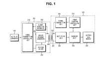
- FIG. 1is a block diagram showing a configuration of a wireless power transmitting system according to an embodiment of the present invention.
- an alternate current (AC) to direct current (DC) converter 100converts an AC power input from the outside into a DC power.
- a wireless power transmitting apparatus 200switches the DC power converted by the AC to DC converter 100 and wirelessly transmits the switched power using, for example, electromagnetic induction.
- FIG. 1depicts an embodiment in which the AC to DC converter 100 is separate from the wireless power transmitting apparatus 200 , it is understood that the AC to DC converter 100 may alternatively be integrated within the wireless power transmitting apparatus 200 without departing from the scope of the present invention.
- a power receiving apparatus 300receives and charges the power wirelessly transmitted by the wireless power transmitting apparatus 200 , generates a transmission signal comprising a unique ID signal and a power charging information signal, and transmits the transmission signal to the wireless power transmitting apparatus 200 .
- the wireless power transmitting apparatus 200may comprise a power transmitting controlling unit 210 , a driving driver 220 , a series resonant converter 230 , a power transmitting coil 240 , and a signal detecting apparatus 250 according to the embodiment of the present invention.
- the power transmitting controlling unit 210controls the wireless transmission of the power to the power receiving apparatus 300 .
- the driving driver 220generates a driving signal which directs the wireless transmission of the power, and the like, under a control of the power transmitting controlling unit 210 .
- the series resonant converter 230switches a DC power supplied from the AC to DC converter 100 , according to the driving signal generated by the driving driver 220 .
- the power transmitting coil 240wirelessly transmits the power while being resonated by the AC power generated by the series resonant converter 230 .
- the signal detecting apparatus 250detects the transmission signal transmitted by the power receiving apparatus 300 from a magnetic field change of the power transmitting coil 240 and provides the detected transmission signal to the power transmitting controlling unit 210 .
- the power receiving apparatus 300may comprise a power charging controlling unit 310 , a power receiving coil 320 , a rectifying unit 330 , a charging unit 340 , a battery cell module 350 , a signal transmitting unit 360 , and the like.
- the power charging controlling unit 310controls a receipt and charging of the power wirelessly transmitted by the wireless power transmitting apparatus 200 and controls a generation, and transmission to the wireless power transmitting apparatus 200 , of the transmission signal comprising the unique ID signal and the power charging information signal.
- the power receiving coil 320is coupled to the power transmitting coil 240 of the power transmitting apparatus 200 in an electromagnetic induction scheme to receive the power wirelessly transmitted by the power transmitting coil 240 .
- the rectifying unit 330rectifies the power received by the power receiving coil 320 into a DC power.
- the charging unit 340charges the DC power rectified by the rectifying unit 530 into the battery cell module 350 , under the control of the power charging controlling unit 310 , and provides the power charging information to the power charging controlling unit 310 .
- the signal transmitting unit 360generates the transmission signal comprising the unique ID signal and the power charging information under the control of the power receiving controlling unit 310 and transmits the generated transmission signal to the wireless power transmitting apparatus 200 through the power receiving coil 320 .
- the AC to DC converter 100converts an AC power, received from an outside source such as an electric outlet, into a DC power, and supplies the converted DC power as an operation power to the wireless power transmitting apparatus 200 , such that the wireless power transmitting apparatus 200 is normally operated.
- the power transmitting controlling unit 210controls the driving driver 220 to generate a driving signal which directs the power transmission.
- the series resonant converter 230switches the DC power outputted from the AC to DC converter 100 , according to the driving signal, to convert the DC power into the AC power, and applies the converted AC power to the power transmitting coil 240 to generate resonance.
- the power transmitting coil 240may be designed to resonate at a frequency of 100 kHz
- the series resonant converter 230may switch the DC power, according to the driving signal, to generate the AC power having the frequency of 100 kHz
- the AC power having the frequency of 100 kHzis applied to the power transmitting coil 240 to generate the resonance. It is understood that other frequencies are possible without departing from the scope of the invention.
- the resonanceWhen the resonance is generated in the power transmitting coil 240 , the power is wirelessly transmitted while a large amount of current flows to the power transmitting coil 240 .
- the power receiving coil 320 of the power receiving apparatus 300receives the power transmitted by the power transmitting coil 240 , the rectifying unit 330 converts the received power into the DC power, and the charging unit 340 charges the converted DC power into the battery cell module 350 under the control of the power charging controlling unit 310 .
- the power charging controlling unit 310determines an amount of power charged in the battery cell module 350 through the charging unit 340 and controls the signal transmitting unit 360 according to the determined amount of power to generate the transmission signal comprising the unique ID signal and the power charging information signal, and the transmission signal generated by the signal transmitting unit 360 is outputted to the power receiving coil 320 .
- the power receiving coil 320generates a magnetic field change according to the transmission signal generated by the signal transmitting unit 360 , and a magnetic field of the power transmitting coil 240 is changed according to the generated magnetic field change.
- the signal detecting circuit 250detects the magnetic field change of the power transmitting coil 240 , detects the transmission signal generated by the signal transmitting unit 360 from the detected magnetic field change, and outputs the detected transmission signal to the power transmitting controlling unit 210 .
- the power transmitting controlling unit 210uses the transmission signal detected by the signal detecting circuit 250 to determine whether or not the power charging of the power receiving apparatus 300 has been completed.
- the power transmitting controlling unit 210continuously performs the operation as described above to continuously wirelessly transmit the power to the power receiving apparatus 300 .
- the power receiving apparatus 300controls the driving driver 220 not to generate the driving signal, thereby stopping the wireless transmission of the power.
- FIG. 2is a block diagram showing a configuration of a signal detecting apparatus 220 according to the embodiment of the present invention.
- a resonance tank circuit 400may comprise a radio frequency identification (RFID) transponder 402 and a capacitor 404 .
- the RFID transponder 402which is disposed close to the power transmitting coil 240 , detects the magnetic field change signal according to the magnetic field change generated in the power transmitting coil 240 .
- the capacitor 404is connected in parallel with the RFID transponder 402 and is resonated by the magnetic field change signal detected by the RFID transponder 402 to generate a resonance signal.
- a signal extracting unit 410extracts the transmission signal transmitted by the power receiving apparatus 300 from the resonance signal of the resonance tank circuit 400 and outputs the extracted transmission signal to the power transmitting controlling unit 210 .
- the signal extracting unit 410may comprise an envelope detecting unit 412 , a low pass filter 414 , an amplifier 416 , and a comparator 418 .
- the envelope detecting unit 412detects an envelope signal from the resonance signal of the resonance tank circuit 400 .
- the low pass filter 414detects and filters a low frequency signal from the envelope signal detected by the envelope detecting unit 412 .
- the amplifier 416amplifies the signal which has been low-pass-filtered by the low pass filter 414 .
- the comparator 418compares the signal amplified by the amplifier 416 with a preset reference voltage to extract the signal transmitted by the power receiving apparatus 300 and outputs the extracted signal to the power transmitting controlling unit 210 .
- the RFID transponder 402 of the resonance tank circuit 400detects the magnetic field change of the power transmitting coil 240 generated according to the transmission signal transmitted by the power receiving apparatus 300 .
- the capacitor 404is connected in parallel with the RFID transponder 402 , and the RFID transponder 402 and the capacitor 404 are resonated in parallel with each other according to the magnetic field change signal detected by the RFID transponder 402 to generate the resonance signal.
- the transmission signal transmitted by the power receiving apparatus 300is transmitted at a predetermined frequency
- the magnetic field changeis generated in the power transmitting coil 240 according to the predetermined frequency of the transmission signal
- the RFID transponder 402 and the capacitor 404are resonated in parallel with each other at the frequency according to the magnetic field change to generate the resonance signal.
- the envelope detecting unit 412 of the signal extracting unit 410detects the envelope signal from the resonance signal. Then, the detected envelope signal is filtered by the low pass filter 414 , amplified by the amplifier 416 , and then inputted into the comparator 418 .
- the comparator 418compares the output signal of the amplifier 416 with a preset reference voltage to extract the transmission signal transmitted by the power receiving apparatus 300 , and outputs the extracted transmission signal to the power transmitting controlling unit 210 . Then, the power transmitting controlling unit 210 determines whether or not the power charging of the power receiving apparatus 300 has been completed using the transmission signal extracted by the comparator 418 .
- FIG. 3is a block diagram showing a configuration of a wireless power transmitting system according to another embodiment of the present invention.
- the wireless power transmitting apparatus 200may comprise two power transmitting coils 240 a and 240 b.
- the series resonant converter 230generates two AC powers and outputs the two AC powers to the two power transmitting coils 240 a and 240 b , respectively, and the two power receiving coils 240 a and 240 b wirelessly transmits the powers while being resonated.
- the wireless power transmitting apparatus 200comprising the two power transmitting coils 240 a and 240 b may be comparable to that of the wireless power transmitting apparatus according to other embodiments of the present invention already described above, a detailed description thereof will be omitted.
- the wireless power transmitting apparatus 200comprise one power transmitting coil 240 or two power transmitting coils 240 a and 240 b have been described above by way of example, the present invention is not limited thereto. That is, the wireless power transmitting apparatus 300 may also comprise three or more power transmitting coils.
- the resonance tank circuitcomprises the RFID transponder detecting the magnetic field change of the power transmitting coil and the capacitor to generate the resonance signal, and the transmission signal transmitted by the power receiving apparatus is extracted from the generated resonance signal.
- a configuration of the circuit extracting the signal transmitted by the power receiving apparatusis significantly uncomplicated, thereby making it possible to decrease a manufacturing cost of the wireless power transmitting apparatus and more precisely detect the transmission signal.
Landscapes
- Engineering & Computer Science (AREA)
- Computer Networks & Wireless Communication (AREA)
- Signal Processing (AREA)
- Power Engineering (AREA)
- Charge And Discharge Circuits For Batteries Or The Like (AREA)
- Near-Field Transmission Systems (AREA)
Abstract
Description
- This application claims priority to Korean Patent Application No. 2011-0138971, filed on Dec. 21, 2011 in the Korean Intellectual Property Office, the disclosure of which is herein incorporated by reference in its entirety.
- 1. Field of the Invention
- The present invention relates to a signal detecting apparatus for detecting transmission signals transmitted by a power receiving apparatus in a wireless power transmitting system, and a wireless power transmitting apparatus having the signal detecting apparatus for detecting transmission signals.
- 2. Description of the Related Art
- Generally, various portable terminals such as cellular phones, smart phones, personal digital assistants (PDAs), and the like, has been mounted with a power receiving apparatus for supplying an operation power thereto.
- The power receiving apparatus, which is charged with a power supplied from an external charging apparatus and supplies the charged power as an operation power to the portable terminal to operate the portable terminal, may comprise a battery cell module charged with the power, a charging and discharging circuit which uses the power supplied from the external charging apparatus to charge the battery cell module and discharges the power charged in the battery cell module to supply the discharged power as the operation power to the portable terminal, and the like.
- In a known method of electrically connecting the charging apparatus to the power receiving apparatus, a terminal through which the power is outputted from the charging apparatus is directly connected to a terminal to which the power is inputted into the power receiving apparatus through a cable, a connector, or the like.
- With the terminal connection method, the terminal of the charging apparatus and the terminal of the power receiving apparatus have different potential differences. Therefore, when the terminals are connected to or disconnected from each other, an instantaneous discharging phenomenon occurs. This instantaneous discharging phenomenon causes abrasion of both terminals. In addition, if foreign materials have accumulated in the terminals, the foreign materials may be heated by the instantaneous discharging phenomenon, such that there is a risk of an accident such as a fire, or the like.
- Further, the power charged in the battery cell module in the power receiving apparatus is naturally discharged into the environment through the terminal of the power receiving apparatus due to moisture, or the like, such that lifespan of the power receiving apparatus may decrease and performance of the power receiving apparatus may deteriorate.
- Recently, a wireless power transmitting system which wirelessly transmits the power has been suggested in order to solve several problems of the terminal connection method as described above.
- In known wireless power transmitting systems, a wireless power transmitting apparatus wirelessly transmits the power using electromagnetic induction. A power receiving apparatus then receives the power wirelessly transmitted by the wireless power transmitting apparatus and charges the received power into the battery cell module.
- Many have sought to improve the described wireless power transmitting system such that the wireless power transmitting apparatus wirelessly transmits the power stably at high efficiency, and such that the power receiving apparatus receives as much of the power transmitted by the wireless power transmitting apparatus as possible to charge the power in the battery cell module.
- In the known wireless power transmitting system described above, the power receiving apparatus generates a transmission signal, including a unique ID signal and a power charging information signal indicating the power charged in the battery cell module, and transmits the transmission signal to the wireless power transmitting apparatus through a power receiving coil, and the wireless power transmitting apparatus receives the transmission signal through a power transmitting coil.
- Since a voltage and a current of the power transmitting coil of the wireless power transmitting apparatus are changed according to the transmission signal transmitted by the power receiving apparatus through the power receiving coil, the wireless power transmitting apparatus may detect the voltage and the current of the power transmitting coil using a voltage sensor, a current sensor, a current transducer, and the like, and determines the detected voltage and current by using a detecting circuit or the like to detect the transmission signal transmitted by the power receiving apparatus.
- Therefore, a configuration of a circuit which detects the transmission signal transmitted by the power receiving apparatus is significantly complicated, such that manufacturing costs increase. Furthermore, there is a limited precision in detecting the transmission signal.
- An object of the present invention is to provide a signal detecting apparatus which can uncomplicatedly detect a transmission signal transmitted by a power receiving apparatus without using a voltage sensor, a current sensor, and a current transducer, and a wireless power transmitting apparatus having the same.
- Another object of the present invention is to provide a signal detecting apparatus which can uncomplicatedly detect a transmission signal using a radio frequency identification (RFID) transponder, and a wireless power transmitting apparatus having the same.
- Still another object of the present invention is to provide a signal detecting apparatus which can precisely detect a transmission signal transmitted by a power receiving apparatus using a magnetic field change signal of a power transmitting coil generated according to the transmission signal, and a wireless power transmitting apparatus having the same.
- Objects of the present invention are not limited to the above-mentioned objects. That is, other objects that are not mentioned may be obviously understood from the following description by those skilled in the relevant art.
- While not limited thereto, according to an embodiment of the present invention, a signal detecting apparatus may comprise a magnetic field change signal detecting unit configured to detect a magnetic field change signal of a power transmitting coil generated according to a transmission signal transmitted by a power receiving apparatus; and a signal extracting unit configured to extract the transmission signal transmitted by the power receiving apparatus from the magnetic field change signal detected by the magnetic field change signal detecting unit.
- According to an aspect of the invention, the magnetic field change signal detecting unit may comprise a resonance tank circuit resonated by the magnetic field change signal of the power transmitting coil to generate a resonance signal.
- According to an aspect of the invention, the resonance tank circuit may comprise a radio frequency identification (RFID) transponder configured to detect the magnetic field change signal of the power transmitting coil; and a capacitor connected in parallel with the RFID transponder to allow resonance to be generated by the magnetic field change signal of the power transmitting coil.
- According to an aspect of the invention, the signal extracting unit may comprise an envelope detecting unit configured to detect an envelope of the magnetic field change signal; a low pass filter configured to filter the envelope detected by the envelope detecting unit; and a comparator configured to compare an output signal of the low pass filter with a preset reference voltage to extract the transmission signal.
- According to an aspect of the invention, the signal extracting unit may further comprise an amplifier disposed between the low pass filter and the comparator and configured to amplify the output signal of the low pass filter and output the amplified signal to the comparator.
- According to an aspect of the invention, the transmission signal may comprise a unique ID signal of the power receiving apparatus and a power charging information signal of the battery cell module.
- According to another embodiment of the present invention, a wireless power transmitting apparatus may comprise a power transmitting coil configured to wirelessly transmit a power to a power receiving apparatus; a signal detecting apparatus configured to use a magnetic field change signal of the power transmitting coil to detect a transmission signal transmitted by the power receiving apparatus; a power transmitting controlling unit configured to control the wirelessly transmission of the power to the power receiving apparatus, and to use the transmission signal detected by the signal detecting apparatus to determine a charged state of the power receiving apparatus; a driving driver configured to generate a driving signal under the control of the power transmitting controlling unit; and a series resonant converter configured to switch a direct current (DC) power according to the driving signal and output the switched power to the power transmitting coil.
- According to an aspect of the invention, the number of power transmitting coils may be one, or two or more.
- According to an aspect of the invention, the wireless power transmitting apparatus may further comprise an alternate current (AC) to direct current (DC) converter configured to convert an AC power into a DC power and supply the DC power as an operation power to the wireless power transmitting apparatus.
- According to an aspect of the invention, the AC to DC converter may be integrated with the wireless power transmitting apparatus.
- According to an aspect of the invention, the signal detecting apparatus may comprise a magnetic field change signal detecting unit configured to detect the magnetic field change signal of the power transmitting coil generated according to the transmission signal; and a signal extracting unit configured to extract the transmission signal transmitted by the power receiving apparatus from the magnetic field change signal detected by the magnetic field change signal detecting unit.
- According to an aspect of the invention, the magnetic field change signal detecting unit may comprise a resonance tank circuit resonated by the magnetic field change signal of the power transmitting coil to generate a resonance signal.
- According to an aspect of the invention, the resonance tank circuit may comprise an RFID transponder configured to detect the magnetic field change signal of the power transmitting coil; and a capacitor connected in parallel with the RFID transponder to allow resonance to be generated by the magnetic field change signal of the power transmitting coil.
- According to an aspect of the invention, the signal extracting unit may comprise an envelope detecting unit configured to detect an envelope of the magnetic field change signal; a low pass filter configured to filter the envelope detected by the envelope detecting unit; and a comparator configured to compare an output signal of the low pass filter with a preset reference voltage to extract the transmission signal.
- According to an aspect of the invention, the signal extracting unit may further comprise an amplifier disposed between the low pass filter and the comparator and configured to amplify the output signal of the low pass filter and output the amplified signal to the comparator.
- According to an aspect of the invention, the transmission signal may comprise a unique ID signal of the power receiving apparatus and a power charging information signal of the battery cell module.
- Additional aspects and/or advantages of the invention will be set forth in part in the description which follows and, in part, will be obvious from the description, or may be learned by practice of the invention.
- These and/or other aspects and advantages of the invention will become apparent and more readily appreciated from the following description of the embodiments, taken in conjunction with the accompanying drawings of which:
FIG. 1 is a block diagram showing a configuration of a wireless power transmitting system, according to an embodiment of the present invention;FIG. 2 is a block diagram showing a configuration of a signal detecting apparatus, according to an embodiment of the present invention; andFIG. 3 is a block diagram showing a configuration of a wireless power transmitting system, according to another embodiment of the present invention.- Hereinafter, the present invention will be described in detail through embodiments thereof with reference to the accompanying drawings, in which the same reference numeral will be used to describe the same component. The embodiments are described below in order to explain the present invention by referring to the figures.
- The following detailed description is only an example and only illustrates embodiments of the present invention. In addition, a principle and a concept of the present invention are provided in order to most usefully and easily describe the present invention. Therefore, for basic understanding of the present invention, a more detailed structure than necessary will not be provided, and several forms of the present invention that may be executed by those skilled in the art will be illustrated in the accompanying drawings.
FIG. 1 is a block diagram showing a configuration of a wireless power transmitting system according to an embodiment of the present invention. In the embodiment depicted inFIG. 1 , an alternate current (AC) to direct current (DC)converter 100 converts an AC power input from the outside into a DC power.- A wireless
power transmitting apparatus 200 switches the DC power converted by the AC toDC converter 100 and wirelessly transmits the switched power using, for example, electromagnetic induction. AlthoughFIG. 1 depicts an embodiment in which the AC toDC converter 100 is separate from the wirelesspower transmitting apparatus 200, it is understood that the AC toDC converter 100 may alternatively be integrated within the wirelesspower transmitting apparatus 200 without departing from the scope of the present invention. - A
power receiving apparatus 300 receives and charges the power wirelessly transmitted by the wirelesspower transmitting apparatus 200, generates a transmission signal comprising a unique ID signal and a power charging information signal, and transmits the transmission signal to the wirelesspower transmitting apparatus 200. - The wireless
power transmitting apparatus 200 may comprise a power transmitting controllingunit 210, adriving driver 220, a seriesresonant converter 230, a power transmittingcoil 240, and asignal detecting apparatus 250 according to the embodiment of the present invention. - The power transmitting controlling
unit 210 controls the wireless transmission of the power to thepower receiving apparatus 300. - The driving
driver 220 generates a driving signal which directs the wireless transmission of the power, and the like, under a control of the powertransmitting controlling unit 210. - The series
resonant converter 230 switches a DC power supplied from the AC toDC converter 100, according to the driving signal generated by the drivingdriver 220. - The
power transmitting coil 240 wirelessly transmits the power while being resonated by the AC power generated by the seriesresonant converter 230. - The
signal detecting apparatus 250 detects the transmission signal transmitted by thepower receiving apparatus 300 from a magnetic field change of thepower transmitting coil 240 and provides the detected transmission signal to the powertransmitting controlling unit 210. - The
power receiving apparatus 300 may comprise a powercharging controlling unit 310, apower receiving coil 320, a rectifyingunit 330, a chargingunit 340, abattery cell module 350, asignal transmitting unit 360, and the like. - The power
charging controlling unit 310 controls a receipt and charging of the power wirelessly transmitted by the wirelesspower transmitting apparatus 200 and controls a generation, and transmission to the wirelesspower transmitting apparatus 200, of the transmission signal comprising the unique ID signal and the power charging information signal. - The
power receiving coil 320 is coupled to thepower transmitting coil 240 of thepower transmitting apparatus 200 in an electromagnetic induction scheme to receive the power wirelessly transmitted by thepower transmitting coil 240. - The rectifying
unit 330 rectifies the power received by thepower receiving coil 320 into a DC power. - The charging
unit 340 charges the DC power rectified by the rectifying unit530 into thebattery cell module 350, under the control of the powercharging controlling unit 310, and provides the power charging information to the powercharging controlling unit 310. - The
signal transmitting unit 360 generates the transmission signal comprising the unique ID signal and the power charging information under the control of the powerreceiving controlling unit 310 and transmits the generated transmission signal to the wirelesspower transmitting apparatus 200 through thepower receiving coil 320. - In the wireless power transmitting system having the above-described configuration, the AC to
DC converter 100 converts an AC power, received from an outside source such as an electric outlet, into a DC power, and supplies the converted DC power as an operation power to the wirelesspower transmitting apparatus 200, such that the wirelesspower transmitting apparatus 200 is normally operated. - In this state, when the wireless
power transmitting apparatus 200 transmits the power to thepower receiving apparatus 300, the powertransmitting controlling unit 210 controls the drivingdriver 220 to generate a driving signal which directs the power transmission. The seriesresonant converter 230 switches the DC power outputted from the AC toDC converter 100, according to the driving signal, to convert the DC power into the AC power, and applies the converted AC power to thepower transmitting coil 240 to generate resonance. - In one embodiment, the
power transmitting coil 240 may be designed to resonate at a frequency of 100 kHz, the seriesresonant converter 230 may switch the DC power, according to the driving signal, to generate the AC power having the frequency of 100 kHz, and the AC power having the frequency of 100 kHz is applied to thepower transmitting coil 240 to generate the resonance. It is understood that other frequencies are possible without departing from the scope of the invention. - When the resonance is generated in the
power transmitting coil 240, the power is wirelessly transmitted while a large amount of current flows to thepower transmitting coil 240. - The
power receiving coil 320 of thepower receiving apparatus 300 receives the power transmitted by thepower transmitting coil 240, the rectifyingunit 330 converts the received power into the DC power, and thecharging unit 340 charges the converted DC power into thebattery cell module 350 under the control of the powercharging controlling unit 310. - In addition, the power
charging controlling unit 310 determines an amount of power charged in thebattery cell module 350 through the chargingunit 340 and controls thesignal transmitting unit 360 according to the determined amount of power to generate the transmission signal comprising the unique ID signal and the power charging information signal, and the transmission signal generated by thesignal transmitting unit 360 is outputted to thepower receiving coil 320. - In this case, the
power receiving coil 320 generates a magnetic field change according to the transmission signal generated by thesignal transmitting unit 360, and a magnetic field of thepower transmitting coil 240 is changed according to the generated magnetic field change. - The
signal detecting circuit 250 detects the magnetic field change of thepower transmitting coil 240, detects the transmission signal generated by thesignal transmitting unit 360 from the detected magnetic field change, and outputs the detected transmission signal to the powertransmitting controlling unit 210. - The power
transmitting controlling unit 210 uses the transmission signal detected by thesignal detecting circuit 250 to determine whether or not the power charging of thepower receiving apparatus 300 has been completed. - If it is determined that the power charging of the
power receiving apparatus 300 has not been completed, the powertransmitting controlling unit 210 continuously performs the operation as described above to continuously wirelessly transmit the power to thepower receiving apparatus 300. - On the other hand, if it is determined that the power charging of the
power receiving apparatus 300 has been completed, thepower receiving apparatus 300 controls the drivingdriver 220 not to generate the driving signal, thereby stopping the wireless transmission of the power. FIG. 2 is a block diagram showing a configuration of asignal detecting apparatus 220 according to the embodiment of the present invention. In the embodiment depicted inFIG. 2 , aresonance tank circuit 400 may comprise a radio frequency identification (RFID)transponder 402 and acapacitor 404. TheRFID transponder 402, which is disposed close to thepower transmitting coil 240, detects the magnetic field change signal according to the magnetic field change generated in thepower transmitting coil 240. In addition, thecapacitor 404 is connected in parallel with theRFID transponder 402 and is resonated by the magnetic field change signal detected by theRFID transponder 402 to generate a resonance signal.- A
signal extracting unit 410 extracts the transmission signal transmitted by thepower receiving apparatus 300 from the resonance signal of theresonance tank circuit 400 and outputs the extracted transmission signal to the powertransmitting controlling unit 210. Thesignal extracting unit 410 may comprise anenvelope detecting unit 412, alow pass filter 414, anamplifier 416, and acomparator 418. - The
envelope detecting unit 412 detects an envelope signal from the resonance signal of theresonance tank circuit 400. - The
low pass filter 414 detects and filters a low frequency signal from the envelope signal detected by theenvelope detecting unit 412. - The
amplifier 416 amplifies the signal which has been low-pass-filtered by thelow pass filter 414. - The
comparator 418 compares the signal amplified by theamplifier 416 with a preset reference voltage to extract the signal transmitted by thepower receiving apparatus 300 and outputs the extracted signal to the powertransmitting controlling unit 210. - In the
signal detecting apparatus 250 according to the embodiment of the present invention having the above-described configuration, theRFID transponder 402 of theresonance tank circuit 400 detects the magnetic field change of thepower transmitting coil 240 generated according to the transmission signal transmitted by thepower receiving apparatus 300. - The
capacitor 404 is connected in parallel with theRFID transponder 402, and theRFID transponder 402 and thecapacitor 404 are resonated in parallel with each other according to the magnetic field change signal detected by theRFID transponder 402 to generate the resonance signal. - In some embodiments, the transmission signal transmitted by the
power receiving apparatus 300 is transmitted at a predetermined frequency, the magnetic field change is generated in thepower transmitting coil 240 according to the predetermined frequency of the transmission signal, and theRFID transponder 402 and thecapacitor 404 are resonated in parallel with each other at the frequency according to the magnetic field change to generate the resonance signal. - The
envelope detecting unit 412 of thesignal extracting unit 410 detects the envelope signal from the resonance signal. Then, the detected envelope signal is filtered by thelow pass filter 414, amplified by theamplifier 416, and then inputted into thecomparator 418. - Next, the
comparator 418 compares the output signal of theamplifier 416 with a preset reference voltage to extract the transmission signal transmitted by thepower receiving apparatus 300, and outputs the extracted transmission signal to the powertransmitting controlling unit 210. Then, the powertransmitting controlling unit 210 determines whether or not the power charging of thepower receiving apparatus 300 has been completed using the transmission signal extracted by thecomparator 418. FIG. 3 is a block diagram showing a configuration of a wireless power transmitting system according to another embodiment of the present invention. Referring to the embodiment depicted inFIG. 3 , the wirelesspower transmitting apparatus 200 according to another embodiment of the present invention may comprise two power transmitting coils240aand240b.- In such an embodiment, the series
resonant converter 230 generates two AC powers and outputs the two AC powers to the two power transmitting coils240aand240b, respectively, and the two power receiving coils240aand240bwirelessly transmits the powers while being resonated. - Since an operation of the wireless
power transmitting apparatus 200 comprising the two power transmitting coils240aand240bmay be comparable to that of the wireless power transmitting apparatus according to other embodiments of the present invention already described above, a detailed description thereof will be omitted. - Additionally, although embodiments in which the wireless
power transmitting apparatus 200 comprise onepower transmitting coil 240 or two power transmitting coils240aand240bhave been described above by way of example, the present invention is not limited thereto. That is, the wirelesspower transmitting apparatus 300 may also comprise three or more power transmitting coils. - With the signal detecting apparatus and the wireless power transmitting apparatus having the same, according to the above-described embodiments of the present invention, the resonance tank circuit comprises the RFID transponder detecting the magnetic field change of the power transmitting coil and the capacitor to generate the resonance signal, and the transmission signal transmitted by the power receiving apparatus is extracted from the generated resonance signal.
- Therefore, a configuration of the circuit extracting the signal transmitted by the power receiving apparatus is significantly uncomplicated, thereby making it possible to decrease a manufacturing cost of the wireless power transmitting apparatus and more precisely detect the transmission signal.
- Although a few embodiments of the present invention have been disclosed for illustrative purposes, those skilled in the art will appreciate that various modifications, additions and substitutions are possible, without departing from the scope and spirit of the invention as disclosed in the accompanying claims. Accordingly, the scope of the present invention is not construed as being limited to the described embodiments but is defined by the appended claims as well as equivalents thereto.
Claims (16)
Applications Claiming Priority (2)
| Application Number | Priority Date | Filing Date | Title |
|---|---|---|---|
| KR1020110138971AKR101254092B1 (en) | 2011-12-21 | 2011-12-21 | Apparatus for detecting signals and wireless power transmission apparatus having the same |
| KR10-2011-0138971 | 2011-12-21 |
Publications (2)
| Publication Number | Publication Date |
|---|---|
| US20130162204A1true US20130162204A1 (en) | 2013-06-27 |
| US9246358B2 US9246358B2 (en) | 2016-01-26 |
Family
ID=47631214
Family Applications (1)
| Application Number | Title | Priority Date | Filing Date |
|---|---|---|---|
| US13/723,980Active2034-01-17US9246358B2 (en) | 2011-12-21 | 2012-12-21 | Wireless power transmitting apparatus having signal detecting circuit for detecting transmission signals |
Country Status (4)
| Country | Link |
|---|---|
| US (1) | US9246358B2 (en) |
| EP (1) | EP2608419B1 (en) |
| KR (1) | KR101254092B1 (en) |
| CN (1) | CN103178622B (en) |
Cited By (21)
| Publication number | Priority date | Publication date | Assignee | Title |
|---|---|---|---|---|
| CN104021414A (en)* | 2014-06-17 | 2014-09-03 | 南宁山风信息科技有限公司 | RFID electronic tag |
| US20140285026A1 (en)* | 2013-03-22 | 2014-09-25 | Kabushiki Kaisha Toshiba | Wireless power supply system, power reception controlling apparatus and power transmission controlling apparatus |
| CN105045330A (en)* | 2015-06-30 | 2015-11-11 | 富达通科技股份有限公司 | Power supply module in induction type power supply and signal analysis circuit thereof |
| US20160079794A1 (en)* | 2014-09-11 | 2016-03-17 | Samsung Electro-Mechanics Co., Ltd. | Wireless charging system and method for controlling the same |
| US9413197B2 (en) | 2010-05-31 | 2016-08-09 | Fu Da Tong Technology Co., Ltd. | Inductive power supply system and intruding metal detection method thereof |
| US9600021B2 (en) | 2011-02-01 | 2017-03-21 | Fu Da Tong Technology Co., Ltd. | Operating clock synchronization adjusting method for induction type power supply system |
| US9628147B2 (en) | 2011-02-01 | 2017-04-18 | Fu Da Tong Technology Co., Ltd. | Method of automatically adjusting determination voltage and voltage adjusting device thereof |
| US9671444B2 (en) | 2011-02-01 | 2017-06-06 | Fu Da Tong Technology Co., Ltd. | Current signal sensing method for supplying-end module of induction type power supply system |
| US9831687B2 (en) | 2011-02-01 | 2017-11-28 | Fu Da Tong Technology Co., Ltd. | Supplying-end module for induction-type power supply system and signal analysis circuit therein |
| US9960639B2 (en) | 2015-01-14 | 2018-05-01 | Fu Da Tong Technology Co., Ltd. | Supplying-end module of induction type power supply system and voltage measurement method thereof |
| US10038338B2 (en) | 2011-02-01 | 2018-07-31 | Fu Da Tong Technology Co., Ltd. | Signal modulation method and signal rectification and modulation device |
| US10056944B2 (en) | 2011-02-01 | 2018-08-21 | Fu Da Tong Technology Co., Ltd. | Data determination method for supplying-end module of induction type power supply system and related supplying-end module |
| US10114396B2 (en) | 2015-10-28 | 2018-10-30 | Fu Da Tong Technology Co., Ltd. | Induction type power supply system and intruding metal detection method thereof |
| US10153665B2 (en) | 2015-01-14 | 2018-12-11 | Fu Da Tong Technology Co., Ltd. | Method for adjusting output power for induction type power supply system and related supplying-end module |
| US20190013701A1 (en)* | 2011-02-01 | 2019-01-10 | Fu Da Tong Technology Co., Ltd. | Intruding metal detection method for induction type power supply system and related supplying-end module |
| US10289142B2 (en) | 2011-02-01 | 2019-05-14 | Fu Da Tong Technology Co., Ltd. | Induction type power supply system and intruding metal detection method thereof |
| US10312748B2 (en) | 2011-02-01 | 2019-06-04 | Fu Da Tong Techology Co., Ltd. | Signal analysis method and circuit |
| US10574095B2 (en) | 2011-02-01 | 2020-02-25 | Fu Da Tong Technology Co., Ltd. | Decoding method for signal processing circuit and signal processing circuit using the same |
| US10615645B2 (en) | 2011-02-01 | 2020-04-07 | Fu Da Tong Technology Co., Ltd | Power supply device of induction type power supply system and NFC device identification method of the same |
| US10630113B2 (en) | 2011-02-01 | 2020-04-21 | Fu Da Tong Technology Co., Ltd | Power supply device of induction type power supply system and RF magnetic card identification method of the same |
| US10673287B2 (en) | 2011-02-01 | 2020-06-02 | Fu Da Tong Technology Co., Ltd. | Method and supplying-end module for detecting receiving-end module |
Families Citing this family (10)
| Publication number | Priority date | Publication date | Assignee | Title |
|---|---|---|---|---|
| TWI472897B (en)* | 2013-05-03 | 2015-02-11 | Fu Da Tong Technology Co Ltd | Method and Device of Automatically Adjusting Determination Voltage And Induction Type Power Supply System Thereof |
| KR101949954B1 (en) | 2013-06-07 | 2019-02-19 | 삼성전자주식회사 | Wireless power transmission apparatus for high efficient energy charging |
| US10148096B2 (en)* | 2014-07-07 | 2018-12-04 | Mediatek Singapore Pte. Ltd. | Wireless or wired power delivery using a controllable power adapter |
| US10068465B2 (en) | 2014-10-22 | 2018-09-04 | Mitutoyo Corporation | Battery-less data transmission module accessory for portable and handheld metrology devices |
| US10222270B2 (en)* | 2015-04-24 | 2019-03-05 | United Arab Emirates University | Temperature monitoring of subject bodies using wireless energy transfer |
| KR20160143044A (en)* | 2015-06-04 | 2016-12-14 | 엘지이노텍 주식회사 | Wireless Power Transfer System and Operating method thereof |
| WO2018070640A1 (en)* | 2016-10-11 | 2018-04-19 | 강동연 | Personal communication terminal in which wireless power charging application is stored, and charging system comprising same |
| JP7083632B2 (en) | 2016-12-29 | 2022-06-13 | 株式会社ミツトヨ | Data transmission module, wireless transmission method and wireless transmission system |
| CN110460357B (en)* | 2019-08-15 | 2021-06-22 | 四川长虹电器股份有限公司 | Near field communication device, communication method and communication equipment based on magnetic field coding |
| US12042043B2 (en) | 2020-06-11 | 2024-07-23 | Kohler Co. | Temperature tracking mirror |
Citations (36)
| Publication number | Priority date | Publication date | Assignee | Title |
|---|---|---|---|---|
| US6486615B2 (en)* | 1998-10-13 | 2002-11-26 | City University Of Hong Kong | Dimming control of electronic ballasts |
| US20030020479A1 (en)* | 2001-07-18 | 2003-01-30 | Vb Autobatterie Gmbh | Electrical rechargeable battery with an electronic circuit integrated in the rechargeable battery container |
| US20060255943A1 (en)* | 2005-05-16 | 2006-11-16 | Psc Scanning, Inc. | Induction charging machine, methods, and system for a data reader |
| US7215251B2 (en)* | 2004-04-13 | 2007-05-08 | Impinj, Inc. | Method and apparatus for controlled persistent ID flag for RFID applications |
| US7271677B2 (en)* | 2003-09-22 | 2007-09-18 | Philip Richard Troyk | Inductive data and power link suitable for integration |
| US20070247084A1 (en)* | 2006-02-11 | 2007-10-25 | Wei Zhao | Power supply based on resonant converter for lamp |
| US7319396B2 (en)* | 2004-08-16 | 2008-01-15 | Abr, Llc | RFID transducer alignment system |
| US20080150476A1 (en)* | 2006-12-22 | 2008-06-26 | Em Microelectronic-Marin S.A. | Battery charger operating "all or nothing" with a protective power supply circuit for monolithic integrated circuits using the antenna energy |
| US7521890B2 (en)* | 2005-12-27 | 2009-04-21 | Power Science Inc. | System and method for selective transfer of radio frequency power |
| US20090157145A1 (en)* | 2007-11-26 | 2009-06-18 | Lawrence Cauller | Transfer Coil Architecture |
| US7579906B2 (en)* | 2004-11-12 | 2009-08-25 | National Semiconductor Corporation | System and method for providing a low power low voltage data detection circuit for RF AM signals in EPC0 compliant RFID tags |
| US20090271047A1 (en)* | 2008-04-28 | 2009-10-29 | Masataka Wakamatsu | Power transmitting apparatus, power receiving apparatus, power transmission method, program, and power transmission system |
| US7659892B2 (en)* | 2005-03-17 | 2010-02-09 | Semiconductor Energy Laboratory Co., Ltd. | Display device and portable terminal |
| US20100127660A1 (en)* | 2008-08-19 | 2010-05-27 | Qualcomm Incorporated | Wireless power transmission for portable wireless power charging |
| US20100160997A1 (en)* | 2001-04-13 | 2010-06-24 | Greatbatch Ltd. | Tuned energy balanced system for minimizing heating and/or to provide emi protection of implanted leads in a high power electromagnetic field environment |
| US20100181963A1 (en)* | 2009-01-20 | 2010-07-22 | Semikron Elektronik Gmbh & Co. Kg | Battery Charger and Method for its Operation |
| US20100181961A1 (en)* | 2009-01-22 | 2010-07-22 | Qualcomm Incorporated | Adaptive power control for wireless charging |
| US20100188870A1 (en)* | 2003-11-06 | 2010-07-29 | Bang & Olufsen A/S | Charge mode control |
| US20100328044A1 (en)* | 2006-10-26 | 2010-12-30 | Koninklijke Philips Electronics N.V. | Inductive power system and method of operation |
| US7952322B2 (en)* | 2006-01-31 | 2011-05-31 | Mojo Mobility, Inc. | Inductive power source and charging system |
| US20110127953A1 (en)* | 2009-11-30 | 2011-06-02 | Broadcom Corporation | Wireless power system |
| US20110140653A1 (en)* | 2008-12-12 | 2011-06-16 | Chun-Kil Jung | Non-Contact Charging Station with Power Transmission Planar Spiral Core, Non-Contact Power-Receiving Apparatus, and Method For Controlling the Same |
| US8159182B2 (en)* | 2007-05-28 | 2012-04-17 | Sony Mobile Communications Japan, Inc. | Contactless power transferring coil unit, mobile terminal, power transmitting apparatus, and contactless power transferring system |
| US20120098486A1 (en)* | 2008-12-12 | 2012-04-26 | Chun-Kil Jung | Non-contact charging station with planar spiral power transmission coil and method for controlling the same |
| US8169185B2 (en)* | 2006-01-31 | 2012-05-01 | Mojo Mobility, Inc. | System and method for inductive charging of portable devices |
| US8222827B2 (en)* | 1999-06-21 | 2012-07-17 | Access Business Group International Llc | Inductively coupled ballast circuit |
| US20120242276A1 (en)* | 2011-03-24 | 2012-09-27 | Hanrim Postech Co., Ltd. | Method for controlling power in wireless power transmission assembly and wireless power assembly thereof |
| US20120256620A1 (en)* | 2011-04-11 | 2012-10-11 | Texas Instruments Incorporated | Systems and Methods of Detecting a Change in Object Presence in a Magnetic Field |
| US8390433B2 (en)* | 2010-04-09 | 2013-03-05 | Eigent Technologies Inc. | Method and system for low cost, power efficient, wireless transponder devices with enhanced functionality |
| US8446046B2 (en)* | 2008-10-03 | 2013-05-21 | Access Business Group International Llc | Power system |
| US8462734B2 (en)* | 2010-10-20 | 2013-06-11 | Nokia Corporation | Wireless docking with out-of-band initiation |
| US8594567B2 (en)* | 2004-08-16 | 2013-11-26 | Giesecke & Devrient Gmbh | Controlled wireless charging of an accumulator in a chipcard |
| US8643326B2 (en)* | 2008-09-27 | 2014-02-04 | Witricity Corporation | Tunable wireless energy transfer systems |
| US8692412B2 (en)* | 2008-09-27 | 2014-04-08 | Witricity Corporation | Temperature compensation in a wireless transfer system |
| US20140152253A1 (en)* | 2009-02-13 | 2014-06-05 | Qualcomm Incorporated | Antenna sharing for wirelessly powered devices |
| US8855554B2 (en)* | 2008-03-05 | 2014-10-07 | Qualcomm Incorporated | Packaging and details of a wireless power device |
Family Cites Families (13)
| Publication number | Priority date | Publication date | Assignee | Title |
|---|---|---|---|---|
| JP3906722B2 (en) | 2002-03-26 | 2007-04-18 | 松下電工株式会社 | Contactless power supply system |
| JP2005242989A (en)* | 2004-01-28 | 2005-09-08 | Toshiba Microelectronics Corp | Non-contact IC card reader / writer terminal device, communication system, and non-contact data carrier |
| US7917088B2 (en)* | 2004-04-13 | 2011-03-29 | Impinj, Inc. | Adaptable detection threshold for RFID tags and chips |
| GB2414120B (en)* | 2004-05-11 | 2008-04-02 | Splashpower Ltd | Controlling inductive power transfer systems |
| US8330594B2 (en)* | 2006-01-30 | 2012-12-11 | Sanyo Electric Co., Ltd. | Tire pressure measuring system and tire pressure measuring device |
| US7989986B2 (en)* | 2006-03-23 | 2011-08-02 | Access Business Group International Llc | Inductive power supply with device identification |
| CN101330229A (en)* | 2007-06-21 | 2008-12-24 | 北京市北邮信息科技发展有限责任公司 | Non-contact type apparatus for transmitting electric energy |
| WO2010020895A2 (en)* | 2008-08-18 | 2010-02-25 | Nxp B.V. | A mobile device to control a charge pad system |
| CN101789921B (en)* | 2009-01-23 | 2013-03-06 | 中芯国际集成电路制造(上海)有限公司 | Amplitude shift keying demodulator and method |
| US8338991B2 (en)* | 2009-03-20 | 2012-12-25 | Qualcomm Incorporated | Adaptive impedance tuning in wireless power transmission |
| KR100976154B1 (en) | 2009-09-29 | 2010-08-17 | 주식회사 한림포스텍 | Non-contact charging system with charging current control function by input power |
| CN201656503U (en)* | 2009-11-19 | 2010-11-24 | 深圳市三子科技有限公司 | Portable wireless chargeable electronic device combination capable of charging |
| KR101055448B1 (en)* | 2011-03-04 | 2011-08-08 | 삼성전기주식회사 | The wireless power transmission apparatus having communication function And Method thereof |
- 2011
- 2011-12-21KRKR1020110138971Apatent/KR101254092B1/enactiveActive
- 2012
- 2012-12-19CNCN201210553739.6Apatent/CN103178622B/enactiveActive
- 2012-12-21EPEP12198951.1Apatent/EP2608419B1/enactiveActive
- 2012-12-21USUS13/723,980patent/US9246358B2/enactiveActive
Patent Citations (39)
| Publication number | Priority date | Publication date | Assignee | Title |
|---|---|---|---|---|
| US6486615B2 (en)* | 1998-10-13 | 2002-11-26 | City University Of Hong Kong | Dimming control of electronic ballasts |
| US8222827B2 (en)* | 1999-06-21 | 2012-07-17 | Access Business Group International Llc | Inductively coupled ballast circuit |
| US20100160997A1 (en)* | 2001-04-13 | 2010-06-24 | Greatbatch Ltd. | Tuned energy balanced system for minimizing heating and/or to provide emi protection of implanted leads in a high power electromagnetic field environment |
| US20030020479A1 (en)* | 2001-07-18 | 2003-01-30 | Vb Autobatterie Gmbh | Electrical rechargeable battery with an electronic circuit integrated in the rechargeable battery container |
| US7271677B2 (en)* | 2003-09-22 | 2007-09-18 | Philip Richard Troyk | Inductive data and power link suitable for integration |
| US20100188870A1 (en)* | 2003-11-06 | 2010-07-29 | Bang & Olufsen A/S | Charge mode control |
| US7215251B2 (en)* | 2004-04-13 | 2007-05-08 | Impinj, Inc. | Method and apparatus for controlled persistent ID flag for RFID applications |
| US7319396B2 (en)* | 2004-08-16 | 2008-01-15 | Abr, Llc | RFID transducer alignment system |
| US8594567B2 (en)* | 2004-08-16 | 2013-11-26 | Giesecke & Devrient Gmbh | Controlled wireless charging of an accumulator in a chipcard |
| US7579906B2 (en)* | 2004-11-12 | 2009-08-25 | National Semiconductor Corporation | System and method for providing a low power low voltage data detection circuit for RF AM signals in EPC0 compliant RFID tags |
| US7659892B2 (en)* | 2005-03-17 | 2010-02-09 | Semiconductor Energy Laboratory Co., Ltd. | Display device and portable terminal |
| US20060255943A1 (en)* | 2005-05-16 | 2006-11-16 | Psc Scanning, Inc. | Induction charging machine, methods, and system for a data reader |
| US7521890B2 (en)* | 2005-12-27 | 2009-04-21 | Power Science Inc. | System and method for selective transfer of radio frequency power |
| US8169185B2 (en)* | 2006-01-31 | 2012-05-01 | Mojo Mobility, Inc. | System and method for inductive charging of portable devices |
| US7952322B2 (en)* | 2006-01-31 | 2011-05-31 | Mojo Mobility, Inc. | Inductive power source and charging system |
| US20070247084A1 (en)* | 2006-02-11 | 2007-10-25 | Wei Zhao | Power supply based on resonant converter for lamp |
| US20100328044A1 (en)* | 2006-10-26 | 2010-12-30 | Koninklijke Philips Electronics N.V. | Inductive power system and method of operation |
| US20080150476A1 (en)* | 2006-12-22 | 2008-06-26 | Em Microelectronic-Marin S.A. | Battery charger operating "all or nothing" with a protective power supply circuit for monolithic integrated circuits using the antenna energy |
| US7952323B2 (en)* | 2006-12-22 | 2011-05-31 | Em Microelectronic-Marin S.A. | Battery charger operating “all or nothing” with a protective power supply circuit for monolithic integrated circuits using the antenna energy |
| US8159182B2 (en)* | 2007-05-28 | 2012-04-17 | Sony Mobile Communications Japan, Inc. | Contactless power transferring coil unit, mobile terminal, power transmitting apparatus, and contactless power transferring system |
| US20090157145A1 (en)* | 2007-11-26 | 2009-06-18 | Lawrence Cauller | Transfer Coil Architecture |
| US8855554B2 (en)* | 2008-03-05 | 2014-10-07 | Qualcomm Incorporated | Packaging and details of a wireless power device |
| US20090271047A1 (en)* | 2008-04-28 | 2009-10-29 | Masataka Wakamatsu | Power transmitting apparatus, power receiving apparatus, power transmission method, program, and power transmission system |
| US8577479B2 (en)* | 2008-04-28 | 2013-11-05 | Sony Corporation | Power transmitting apparatus, power receiving apparatus, power transmission method, program, and power transmission system |
| US20100127660A1 (en)* | 2008-08-19 | 2010-05-27 | Qualcomm Incorporated | Wireless power transmission for portable wireless power charging |
| US8692412B2 (en)* | 2008-09-27 | 2014-04-08 | Witricity Corporation | Temperature compensation in a wireless transfer system |
| US8643326B2 (en)* | 2008-09-27 | 2014-02-04 | Witricity Corporation | Tunable wireless energy transfer systems |
| US8446046B2 (en)* | 2008-10-03 | 2013-05-21 | Access Business Group International Llc | Power system |
| US20110140653A1 (en)* | 2008-12-12 | 2011-06-16 | Chun-Kil Jung | Non-Contact Charging Station with Power Transmission Planar Spiral Core, Non-Contact Power-Receiving Apparatus, and Method For Controlling the Same |
| US20120098486A1 (en)* | 2008-12-12 | 2012-04-26 | Chun-Kil Jung | Non-contact charging station with planar spiral power transmission coil and method for controlling the same |
| US20100181963A1 (en)* | 2009-01-20 | 2010-07-22 | Semikron Elektronik Gmbh & Co. Kg | Battery Charger and Method for its Operation |
| US8497658B2 (en)* | 2009-01-22 | 2013-07-30 | Qualcomm Incorporated | Adaptive power control for wireless charging of devices |
| US20100181961A1 (en)* | 2009-01-22 | 2010-07-22 | Qualcomm Incorporated | Adaptive power control for wireless charging |
| US20140152253A1 (en)* | 2009-02-13 | 2014-06-05 | Qualcomm Incorporated | Antenna sharing for wirelessly powered devices |
| US20110127953A1 (en)* | 2009-11-30 | 2011-06-02 | Broadcom Corporation | Wireless power system |
| US8390433B2 (en)* | 2010-04-09 | 2013-03-05 | Eigent Technologies Inc. | Method and system for low cost, power efficient, wireless transponder devices with enhanced functionality |
| US8462734B2 (en)* | 2010-10-20 | 2013-06-11 | Nokia Corporation | Wireless docking with out-of-band initiation |
| US20120242276A1 (en)* | 2011-03-24 | 2012-09-27 | Hanrim Postech Co., Ltd. | Method for controlling power in wireless power transmission assembly and wireless power assembly thereof |
| US20120256620A1 (en)* | 2011-04-11 | 2012-10-11 | Texas Instruments Incorporated | Systems and Methods of Detecting a Change in Object Presence in a Magnetic Field |
Cited By (24)
| Publication number | Priority date | Publication date | Assignee | Title |
|---|---|---|---|---|
| US9413197B2 (en) | 2010-05-31 | 2016-08-09 | Fu Da Tong Technology Co., Ltd. | Inductive power supply system and intruding metal detection method thereof |
| US10056944B2 (en) | 2011-02-01 | 2018-08-21 | Fu Da Tong Technology Co., Ltd. | Data determination method for supplying-end module of induction type power supply system and related supplying-end module |
| US9831687B2 (en) | 2011-02-01 | 2017-11-28 | Fu Da Tong Technology Co., Ltd. | Supplying-end module for induction-type power supply system and signal analysis circuit therein |
| US10673287B2 (en) | 2011-02-01 | 2020-06-02 | Fu Da Tong Technology Co., Ltd. | Method and supplying-end module for detecting receiving-end module |
| US10630116B2 (en)* | 2011-02-01 | 2020-04-21 | Fu Da Tong Technology Co., Ltd. | Intruding metal detection method for induction type power supply system and related supplying-end module |
| US9600021B2 (en) | 2011-02-01 | 2017-03-21 | Fu Da Tong Technology Co., Ltd. | Operating clock synchronization adjusting method for induction type power supply system |
| US9628147B2 (en) | 2011-02-01 | 2017-04-18 | Fu Da Tong Technology Co., Ltd. | Method of automatically adjusting determination voltage and voltage adjusting device thereof |
| US9671444B2 (en) | 2011-02-01 | 2017-06-06 | Fu Da Tong Technology Co., Ltd. | Current signal sensing method for supplying-end module of induction type power supply system |
| US10630113B2 (en) | 2011-02-01 | 2020-04-21 | Fu Da Tong Technology Co., Ltd | Power supply device of induction type power supply system and RF magnetic card identification method of the same |
| US10615645B2 (en) | 2011-02-01 | 2020-04-07 | Fu Da Tong Technology Co., Ltd | Power supply device of induction type power supply system and NFC device identification method of the same |
| US10594168B2 (en) | 2011-02-01 | 2020-03-17 | Fu Da Tong Technology Co., Ltd. | Intruding metal detection method for induction type power supply system and related supplying-end module |
| US10574095B2 (en) | 2011-02-01 | 2020-02-25 | Fu Da Tong Technology Co., Ltd. | Decoding method for signal processing circuit and signal processing circuit using the same |
| US10038338B2 (en) | 2011-02-01 | 2018-07-31 | Fu Da Tong Technology Co., Ltd. | Signal modulation method and signal rectification and modulation device |
| US10312748B2 (en) | 2011-02-01 | 2019-06-04 | Fu Da Tong Techology Co., Ltd. | Signal analysis method and circuit |
| US10289142B2 (en) | 2011-02-01 | 2019-05-14 | Fu Da Tong Technology Co., Ltd. | Induction type power supply system and intruding metal detection method thereof |
| US20190013701A1 (en)* | 2011-02-01 | 2019-01-10 | Fu Da Tong Technology Co., Ltd. | Intruding metal detection method for induction type power supply system and related supplying-end module |
| US20140285026A1 (en)* | 2013-03-22 | 2014-09-25 | Kabushiki Kaisha Toshiba | Wireless power supply system, power reception controlling apparatus and power transmission controlling apparatus |
| CN104021414A (en)* | 2014-06-17 | 2014-09-03 | 南宁山风信息科技有限公司 | RFID electronic tag |
| US9762084B2 (en)* | 2014-09-11 | 2017-09-12 | Samsung Electro-Mechanics Co., Ltd. | Wireless charging system and method for controlling the same |
| US20160079794A1 (en)* | 2014-09-11 | 2016-03-17 | Samsung Electro-Mechanics Co., Ltd. | Wireless charging system and method for controlling the same |
| US10153665B2 (en) | 2015-01-14 | 2018-12-11 | Fu Da Tong Technology Co., Ltd. | Method for adjusting output power for induction type power supply system and related supplying-end module |
| US9960639B2 (en) | 2015-01-14 | 2018-05-01 | Fu Da Tong Technology Co., Ltd. | Supplying-end module of induction type power supply system and voltage measurement method thereof |
| CN105045330A (en)* | 2015-06-30 | 2015-11-11 | 富达通科技股份有限公司 | Power supply module in induction type power supply and signal analysis circuit thereof |
| US10114396B2 (en) | 2015-10-28 | 2018-10-30 | Fu Da Tong Technology Co., Ltd. | Induction type power supply system and intruding metal detection method thereof |
Also Published As
| Publication number | Publication date |
|---|---|
| EP2608419B1 (en) | 2024-10-09 |
| KR101254092B1 (en) | 2013-04-12 |
| CN103178622A (en) | 2013-06-26 |
| US9246358B2 (en) | 2016-01-26 |
| EP2608419A3 (en) | 2013-07-24 |
| CN103178622B (en) | 2018-05-04 |
| EP2608419A2 (en) | 2013-06-26 |
Similar Documents
| Publication | Publication Date | Title |
|---|---|---|
| US9246358B2 (en) | Wireless power transmitting apparatus having signal detecting circuit for detecting transmission signals | |
| US9191075B2 (en) | Wireless power control method, system, and apparatus utilizing a wakeup signal to prevent standby power consumption | |
| US9130380B2 (en) | Contactless power transmitting system having overheat protection function and method thereof | |
| US9124123B2 (en) | Wireless power transmitting apparatus and method | |
| EP2730007B1 (en) | Energy receiver, detection method and power transmission system | |
| US9391463B2 (en) | Device and method for wirelessly transmitting power | |
| US9425629B2 (en) | Wireless power receiver | |
| JP6772190B2 (en) | Contactless power transmission | |
| JP6279452B2 (en) | Non-contact power transmission device | |
| KR101774727B1 (en) | Wireless power supply system and wireless power reception device | |
| EP2598363A1 (en) | Resonance type non-contact power supply system | |
| EP2866328B1 (en) | Non-contact power transmission device | |
| WO2013077326A1 (en) | Non-contact power supply apparatus and non-contact power supply system | |
| KR20150106274A (en) | Wireless Power Transfer System including Wireless Power Transfer System-Charger | |
| WO2012014483A1 (en) | Resonance type non-contact power supply system | |
| JP6977654B2 (en) | Wireless power receiving device and wireless power transmission system | |
| US9660479B2 (en) | Device and method for wirelessly transmitting power | |
| JP6406955B2 (en) | Electronics | |
| US11641134B2 (en) | Wireless charging device and a method for detecting a receiver device | |
| KR20180106217A (en) | Device for transmitting and receiving wireless power, and electronic terminal, auxiliary battery, auxiliary apparatus with the same | |
| US20130241301A1 (en) | Power transmission device and power feeding system | |
| US20130082649A1 (en) | Wireless charging system | |
| KR101254258B1 (en) | Method for controlling wireles power transmission in wireless power transmission device and wireless power transmission device using the same | |
| JP2017085784A (en) | Power supply system |
Legal Events
| Date | Code | Title | Description |
|---|---|---|---|
| AS | Assignment | Owner name:HANRIM POSTECH CO., LTD., KOREA, REPUBLIC OF Free format text:ASSIGNMENT OF ASSIGNORS INTEREST;ASSIGNORS:JUNG, CHUN-KIL;SHON, SOO-DONG;REEL/FRAME:029740/0058 Effective date:20130129 | |
| STCF | Information on status: patent grant | Free format text:PATENTED CASE | |
| AS | Assignment | Owner name:GE HYBRID TECHNOLOGIES, LLC, NEW YORK Free format text:ASSIGNMENT OF ASSIGNORS INTEREST;ASSIGNOR:HANRIM POSTECH CO., LTD;REEL/FRAME:044660/0188 Effective date:20180102 | |
| MAFP | Maintenance fee payment | Free format text:PAYMENT OF MAINTENANCE FEE, 4TH YR, SMALL ENTITY (ORIGINAL EVENT CODE: M2551); ENTITY STATUS OF PATENT OWNER: SMALL ENTITY Year of fee payment:4 | |
| MAFP | Maintenance fee payment | Free format text:PAYMENT OF MAINTENANCE FEE, 8TH YR, SMALL ENTITY (ORIGINAL EVENT CODE: M2552); ENTITY STATUS OF PATENT OWNER: SMALL ENTITY Year of fee payment:8 | |
| AS | Assignment | Owner name:EDISON INNOVATIONS, LLC, TEXAS Free format text:ASSIGNMENT OF ASSIGNORS INTEREST;ASSIGNOR:DOLBY HYBRID TECHNOLOGIES, LLC;REEL/FRAME:070287/0538 Effective date:20250219 | |
| AS | Assignment | Owner name:DOLBY HYBRID TECHNOLOGIES, LLC, NEW YORK Free format text:CHANGE OF NAME;ASSIGNOR:GE HYBRID TECHNOLOGIES, LLC;REEL/FRAME:070722/0250 Effective date:20240819 |