US20130150906A1 - System and method for a lockable polyaxial driver tool - Google Patents
System and method for a lockable polyaxial driver toolDownload PDFInfo
- Publication number
- US20130150906A1 US20130150906A1US13/713,137US201213713137AUS2013150906A1US 20130150906 A1US20130150906 A1US 20130150906A1US 201213713137 AUS201213713137 AUS 201213713137AUS 2013150906 A1US2013150906 A1US 2013150906A1
- Authority
- US
- United States
- Prior art keywords
- elongated shaft
- elongated
- main axis
- distal component
- tubular body
- Prior art date
- Legal status (The legal status is an assumption and is not a legal conclusion. Google has not performed a legal analysis and makes no representation as to the accuracy of the status listed.)
- Granted
Links
Images


Classifications
- A—HUMAN NECESSITIES
- A61—MEDICAL OR VETERINARY SCIENCE; HYGIENE
- A61B—DIAGNOSIS; SURGERY; IDENTIFICATION
- A61B17/00—Surgical instruments, devices or methods
- A61B17/56—Surgical instruments or methods for treatment of bones or joints; Devices specially adapted therefor
- A61B17/58—Surgical instruments or methods for treatment of bones or joints; Devices specially adapted therefor for osteosynthesis, e.g. bone plates, screws or setting implements
- A61B17/68—Internal fixation devices, including fasteners and spinal fixators, even if a part thereof projects from the skin
- A61B17/70—Spinal positioners or stabilisers, e.g. stabilisers comprising fluid filler in an implant
- A61B17/7074—Tools specially adapted for spinal fixation operations other than for bone removal or filler handling
- A—HUMAN NECESSITIES
- A61—MEDICAL OR VETERINARY SCIENCE; HYGIENE
- A61B—DIAGNOSIS; SURGERY; IDENTIFICATION
- A61B17/00—Surgical instruments, devices or methods
- A61B17/56—Surgical instruments or methods for treatment of bones or joints; Devices specially adapted therefor
- A61B17/58—Surgical instruments or methods for treatment of bones or joints; Devices specially adapted therefor for osteosynthesis, e.g. bone plates, screws or setting implements
- A61B17/68—Internal fixation devices, including fasteners and spinal fixators, even if a part thereof projects from the skin
- A61B17/80—Cortical plates, i.e. bone plates; Instruments for holding or positioning cortical plates, or for compressing bones attached to cortical plates
- A61B17/808—Instruments for holding or positioning bone plates, or for adjusting screw-to-plate locking mechanisms
- A—HUMAN NECESSITIES
- A61—MEDICAL OR VETERINARY SCIENCE; HYGIENE
- A61F—FILTERS IMPLANTABLE INTO BLOOD VESSELS; PROSTHESES; DEVICES PROVIDING PATENCY TO, OR PREVENTING COLLAPSING OF, TUBULAR STRUCTURES OF THE BODY, e.g. STENTS; ORTHOPAEDIC, NURSING OR CONTRACEPTIVE DEVICES; FOMENTATION; TREATMENT OR PROTECTION OF EYES OR EARS; BANDAGES, DRESSINGS OR ABSORBENT PADS; FIRST-AID KITS
- A61F2/00—Filters implantable into blood vessels; Prostheses, i.e. artificial substitutes or replacements for parts of the body; Appliances for connecting them with the body; Devices providing patency to, or preventing collapsing of, tubular structures of the body, e.g. stents
- A61F2/02—Prostheses implantable into the body
- A61F2/30—Joints
- A61F2/46—Special tools for implanting artificial joints
- A61F2/4603—Special tools for implanting artificial joints for insertion or extraction of endoprosthetic joints or of accessories thereof
- A61F2/4611—Special tools for implanting artificial joints for insertion or extraction of endoprosthetic joints or of accessories thereof of spinal prostheses
- A—HUMAN NECESSITIES
- A61—MEDICAL OR VETERINARY SCIENCE; HYGIENE
- A61F—FILTERS IMPLANTABLE INTO BLOOD VESSELS; PROSTHESES; DEVICES PROVIDING PATENCY TO, OR PREVENTING COLLAPSING OF, TUBULAR STRUCTURES OF THE BODY, e.g. STENTS; ORTHOPAEDIC, NURSING OR CONTRACEPTIVE DEVICES; FOMENTATION; TREATMENT OR PROTECTION OF EYES OR EARS; BANDAGES, DRESSINGS OR ABSORBENT PADS; FIRST-AID KITS
- A61F2/00—Filters implantable into blood vessels; Prostheses, i.e. artificial substitutes or replacements for parts of the body; Appliances for connecting them with the body; Devices providing patency to, or preventing collapsing of, tubular structures of the body, e.g. stents
- A61F2/02—Prostheses implantable into the body
- A61F2/30—Joints
- A61F2002/30001—Additional features of subject-matter classified in A61F2/28, A61F2/30 and subgroups thereof
- A61F2002/30316—The prosthesis having different structural features at different locations within the same prosthesis; Connections between prosthetic parts; Special structural features of bone or joint prostheses not otherwise provided for
- A61F2002/30535—Special structural features of bone or joint prostheses not otherwise provided for
- A61F2002/30537—Special structural features of bone or joint prostheses not otherwise provided for adjustable
- A61F2002/30538—Special structural features of bone or joint prostheses not otherwise provided for adjustable for adjusting angular orientation
- A—HUMAN NECESSITIES
- A61—MEDICAL OR VETERINARY SCIENCE; HYGIENE
- A61F—FILTERS IMPLANTABLE INTO BLOOD VESSELS; PROSTHESES; DEVICES PROVIDING PATENCY TO, OR PREVENTING COLLAPSING OF, TUBULAR STRUCTURES OF THE BODY, e.g. STENTS; ORTHOPAEDIC, NURSING OR CONTRACEPTIVE DEVICES; FOMENTATION; TREATMENT OR PROTECTION OF EYES OR EARS; BANDAGES, DRESSINGS OR ABSORBENT PADS; FIRST-AID KITS
- A61F2/00—Filters implantable into blood vessels; Prostheses, i.e. artificial substitutes or replacements for parts of the body; Appliances for connecting them with the body; Devices providing patency to, or preventing collapsing of, tubular structures of the body, e.g. stents
- A61F2/02—Prostheses implantable into the body
- A61F2/30—Joints
- A61F2002/30001—Additional features of subject-matter classified in A61F2/28, A61F2/30 and subgroups thereof
- A61F2002/30316—The prosthesis having different structural features at different locations within the same prosthesis; Connections between prosthetic parts; Special structural features of bone or joint prostheses not otherwise provided for
- A61F2002/30535—Special structural features of bone or joint prostheses not otherwise provided for
- A61F2002/30593—Special structural features of bone or joint prostheses not otherwise provided for hollow
- A—HUMAN NECESSITIES
- A61—MEDICAL OR VETERINARY SCIENCE; HYGIENE
- A61F—FILTERS IMPLANTABLE INTO BLOOD VESSELS; PROSTHESES; DEVICES PROVIDING PATENCY TO, OR PREVENTING COLLAPSING OF, TUBULAR STRUCTURES OF THE BODY, e.g. STENTS; ORTHOPAEDIC, NURSING OR CONTRACEPTIVE DEVICES; FOMENTATION; TREATMENT OR PROTECTION OF EYES OR EARS; BANDAGES, DRESSINGS OR ABSORBENT PADS; FIRST-AID KITS
- A61F2/00—Filters implantable into blood vessels; Prostheses, i.e. artificial substitutes or replacements for parts of the body; Appliances for connecting them with the body; Devices providing patency to, or preventing collapsing of, tubular structures of the body, e.g. stents
- A61F2/02—Prostheses implantable into the body
- A61F2/30—Joints
- A61F2/30767—Special external or bone-contacting surface, e.g. coating for improving bone ingrowth
- A61F2/30771—Special external or bone-contacting surface, e.g. coating for improving bone ingrowth applied in original prostheses, e.g. holes or grooves
- A61F2002/30772—Apertures or holes, e.g. of circular cross section
- A61F2002/30774—Apertures or holes, e.g. of circular cross section internally-threaded
- A—HUMAN NECESSITIES
- A61—MEDICAL OR VETERINARY SCIENCE; HYGIENE
- A61F—FILTERS IMPLANTABLE INTO BLOOD VESSELS; PROSTHESES; DEVICES PROVIDING PATENCY TO, OR PREVENTING COLLAPSING OF, TUBULAR STRUCTURES OF THE BODY, e.g. STENTS; ORTHOPAEDIC, NURSING OR CONTRACEPTIVE DEVICES; FOMENTATION; TREATMENT OR PROTECTION OF EYES OR EARS; BANDAGES, DRESSINGS OR ABSORBENT PADS; FIRST-AID KITS
- A61F2/00—Filters implantable into blood vessels; Prostheses, i.e. artificial substitutes or replacements for parts of the body; Appliances for connecting them with the body; Devices providing patency to, or preventing collapsing of, tubular structures of the body, e.g. stents
- A61F2/02—Prostheses implantable into the body
- A61F2/30—Joints
- A61F2/30767—Special external or bone-contacting surface, e.g. coating for improving bone ingrowth
- A61F2/30771—Special external or bone-contacting surface, e.g. coating for improving bone ingrowth applied in original prostheses, e.g. holes or grooves
- A61F2002/30772—Apertures or holes, e.g. of circular cross section
- A61F2002/30777—Oblong apertures
- A—HUMAN NECESSITIES
- A61—MEDICAL OR VETERINARY SCIENCE; HYGIENE
- A61F—FILTERS IMPLANTABLE INTO BLOOD VESSELS; PROSTHESES; DEVICES PROVIDING PATENCY TO, OR PREVENTING COLLAPSING OF, TUBULAR STRUCTURES OF THE BODY, e.g. STENTS; ORTHOPAEDIC, NURSING OR CONTRACEPTIVE DEVICES; FOMENTATION; TREATMENT OR PROTECTION OF EYES OR EARS; BANDAGES, DRESSINGS OR ABSORBENT PADS; FIRST-AID KITS
- A61F2/00—Filters implantable into blood vessels; Prostheses, i.e. artificial substitutes or replacements for parts of the body; Appliances for connecting them with the body; Devices providing patency to, or preventing collapsing of, tubular structures of the body, e.g. stents
- A61F2/02—Prostheses implantable into the body
- A61F2/30—Joints
- A61F2/30767—Special external or bone-contacting surface, e.g. coating for improving bone ingrowth
- A61F2/30771—Special external or bone-contacting surface, e.g. coating for improving bone ingrowth applied in original prostheses, e.g. holes or grooves
- A61F2002/30772—Apertures or holes, e.g. of circular cross section
- A61F2002/30784—Plurality of holes
- A61F2002/30787—Plurality of holes inclined obliquely with respect to each other
- A—HUMAN NECESSITIES
- A61—MEDICAL OR VETERINARY SCIENCE; HYGIENE
- A61F—FILTERS IMPLANTABLE INTO BLOOD VESSELS; PROSTHESES; DEVICES PROVIDING PATENCY TO, OR PREVENTING COLLAPSING OF, TUBULAR STRUCTURES OF THE BODY, e.g. STENTS; ORTHOPAEDIC, NURSING OR CONTRACEPTIVE DEVICES; FOMENTATION; TREATMENT OR PROTECTION OF EYES OR EARS; BANDAGES, DRESSINGS OR ABSORBENT PADS; FIRST-AID KITS
- A61F2/00—Filters implantable into blood vessels; Prostheses, i.e. artificial substitutes or replacements for parts of the body; Appliances for connecting them with the body; Devices providing patency to, or preventing collapsing of, tubular structures of the body, e.g. stents
- A61F2/02—Prostheses implantable into the body
- A61F2/30—Joints
- A61F2/46—Special tools for implanting artificial joints
- A61F2/4603—Special tools for implanting artificial joints for insertion or extraction of endoprosthetic joints or of accessories thereof
- A61F2002/4629—Special tools for implanting artificial joints for insertion or extraction of endoprosthetic joints or of accessories thereof connected to the endoprosthesis or implant via a threaded connection
Definitions
- the present inventionrelates to a system and a method for a driver tool for inserting a surgically implantable device, and in particular, to a driver that is lockable and transfers motion to the implantable device through a polyaxial joint.
- spinal cages or connecting elementssuch as rods, plates or wires are implanted and fixed between two adjacent vertebras or two or more other locations of the spine. Placement of these spacers, cages, connecting elements or other implants is desirably performed via minimally invasive spinal surgeries.
- the orientation of these implants during implantationis critical for the overall success of the procedure. Accordingly there is a need for improved methods, tools and devices that allow insertion of spinal implants in a controlled orientation via minimally invasive surgery.
- the present inventionprovides a driver tool for inserting a surgically implantable device.
- the driveris lockable in a precise orientation and transfers motion to the implantable device through a polyaxial joint. In the unlocked position the driver provides polyaxial orientation of the implantable device.
- the inventionfeatures a polyaxial driver system for inserting and setting the angular orientation of an implant including an elongated component and a distal component.
- the elongated componentextends along a main axis and includes an elongated tubular sheath and an elongated shaft disposed within the tubular sheath.
- the distal componentis pivotally connected to a distal end of the elongated shaft and includes a tubular body extending along the main axis and a spherical head dimensioned to fit and move freely within the tubular body.
- a proximal end of the elongated shaftincludes a first set of outer threads and a proximal end of the elongated tubular sheath includes inner threads shaped and dimensioned to engage the first set of outer threads of the elongated shaft.
- Rotating the elongated tubular sheath clockwise or counter-clockwisemoves the elongated shaft forward or backward along the main axis, respectively.
- the distal end of the elongated shaftincludes a second set of outer threads.
- the second set of outer threadsare shaped and dimensioned to engage inner threads formed in the distal component.
- Rotating the elongated shaft clockwise or counter-clockwisecauses the second set of outer threads to engage or disengage the inner threads of the distal component and thereby the elongated shaft engages or disengages the distal component, respectively.
- the spherical headis configured to move longitudinally along the main axis and to pivot relative to the main axis within the tubular body.
- the systemfurther includes a setscrew having a threaded body and a head.
- the tubular body of the distal componentincludes a slot extending along the main axis and having a width smaller than the diameter of the setscrew head and larger than the diameter of the setscrew threaded body.
- the spherical headfurther includes a threaded opening dimensioned to receive the setscrew. Screwing the setscrew into the spherical head threaded opening secures the position and angular orientation of the spherical head within the tubular body and relative to the main axis.
- the systemfurther includes a rod extending from the spherical head. The spherical head is oriented within the tubular body of the distal component so that the rod is positioned outside of the tubular body at all times.
- the rodhas outer threads shaped and dimensioned to engage inner threads formed within an opening of an implant.
- the rodhas a bayonet connector and is configure to connect to an implant via the bayonet connector.
- the systemfurther includes a handle configured to be attached to the proximal end of the elongated shaft.
- the handlehas a cylindrical body having a thumb indentation configured to provide tactile control of the orientation of an implant attached to the distal component.
- a distal end of the tubular sheathincludes the tubular body of the distal component.
- the inventionfeatures a method for inserting and setting the angular orientation of an implant including the following. First, providing an elongated component extending along a main axis and comprising an elongated tubular sheath and an elongated shaft disposed within the tubular sheath. Next, providing a distal component and pivotally connecting the distal component to a distal end of the elongated shaft.
- the distal componentincludes a tubular body extending along the main axis and a spherical head dimensioned to fit and move freely within the tubular body.
- a proximal end of the elongated shaftincludes a first set of outer threads and a proximal end of the elongated tubular sheath includes inner threads shaped and dimensioned to engage the first set of outer threads of the elongated shaft.
- Rotating the elongated tubular sheath clockwise or counter-clockwisemoves the elongated shaft forward or backward along the main axis, respectively.
- the spherical headincludes a threaded opening dimensioned to receive a setscrew. Screwing the setscrew into the spherical head threaded opening secures the position and angular orientation of the spherical head within the tubular body and relative to the main axis.
- the methodfurther includes attaching an implant to the distal component, setting and locking the position and angular orientation of the distal component relative to the main axis, rotating the elongated tubular sheath clockwise to move the elongated shaft forward along the main axis over the setscrew and inserting the implant.
- the lockable polyaxial driver tool of this inventionprovides flexibility and accuracy in the positioning and orientation of an implant.
- the precise orientation of the implantmay reduce the duration of the surgical procedure and may contribute to the overall therapeutic success of the surgery.
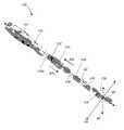
- FIG. 1is a perspective view of a lockable polyaxial driver of this invention
- FIG. 2is an enlarged perspective view of the distal end of the lockable polyaxial driver of FIG. 1 ;
- FIG. 3is a top perspective view of the distal end of the lockable polyaxial driver of FIG. 1 ;
- FIG. 4is a side view of the distal end of the lockable polyaxial driver of FIG. 1 ;
- FIG. 5is an enlarged top view of the distal end of the lockable polyaxial driver of FIG. 1 ;
- FIG. 6is an enlarged perspective view of the handle connection to the lockable polyaxial driver of FIG. 1 ;
- the present inventionprovides a driver tool for inserting a surgically implantable device.
- the driver toolincludes a handle and an elongated shaft with a polyaxially attachable distal end. The orientation of the distal end is lockable and transfers motion to the implantable device through a polyaxial joint. In the unlocked position the driver provides at least three degrees of freedom motion to the implantable device.
- driver tool 100includes an elongated component 120 , a handle 110 and a distal component 130 .
- the elongated component 120extends along axis 82 and includes an elongated tubular outer sheath 125 and an elongated shaft 126 disposed within the outer sheath 125 .
- the proximal end 126 a of the elongated shaft 126is attached to the handle 110 and includes a first set of outer threads 122 .
- Outer threads 122are shaped and dimensioned to engage inner threads 123 formed in the inner surface of the proximal end of outer sheath 125 .
- the distal end 126 b of the elongated shaft 126includes a second set of outer threads 128 .
- Outer threads 128are shaped and dimensioned to engage inner threads formed in the distal component 130 .
- Rotating the handle 110clockwise or counter-clockwise threads the outer threads 128 into or out of the distal component 130 and thereby engages or disengages the distal component 130 , respectively.
- Distal component 130includes a cylindrically shaped tubular body 132 having a slot 134 .
- Slot 134is formed on the side surface of body 132 , extends along the elongated axis 82 and has a closed end 134 a and an open-end 134 b.
- Distal component 130also includes a spherical head 136 dimensioned to fit and move freely within the tubular body 132 .
- Spherical head 136moves longitudinally along axis 82 , and rotates around axis 82 .
- Spherical head 136is also dimensioned to pivot relative to axis 82 and to assume any angle relative to the plane formed by the two intersecting axes 84 and 86 that are perpendicular to axis 82 and perpendicular to each other, as shown in FIG. 1 .
- Spherical head 136also includes a rod 137 extending from its base and the head 136 is oriented within the tubular body 132 , so that rod 137 is positioned outside of the tubular body 132 at all times.
- Rod 137includes outer threads 138 at its distal end and the outer threads 138 are shaped and dimensioned to engage inner threads formed in a cavity or a through aperture 90 a of the implant 90 , as shown in FIG. 4 . Threading outer threads 138 into or out of threaded aperture 90 a attaches or detaches implant 90 to or from the driver tool 100 , respectively.
- the top of spherical head 136also includes a threaded opening 141 dimensioned to receive a setscrew 139 .
- Setscrew 139includes a threaded body (not shown) and a head 139 a.
- Setscrew head 139 ahas a diameter that is slightly larger than the width of the elongated slot 134 and the threaded body has a diameter that is slightly smaller than the width of the elongated slot 134 .
- the dimensions of the set screw 139are chosen so that the threaded body is placed through the elongated slot 134 and is threaded into the threaded opening 141 of the spherical head 136 and the setscrew head 139 a remains above the elongated slot 134 , thereby securing the orientation of the spherical head 136 within the tubular body 132 .
- the setscrew head 139 aincludes a slot 142 used for engaging a screwdriver.
- Handle 110includes a cylindrical body having a thumb indentation 111 used to provide tactile control of the implant 90 orientation.
- implant 90is attached to the distal component 130 by threading threads 138 into the aperture 90 a and then its orientation is set relative to the plane defined by the intersecting axes 84 , 86 at any desired angle by pivoting and rotating the spherical head 136 within the tubular body 132 .
- the set screw 139is placed through the elongated slot 134 and is screwed into the spherical head opening 141 to secure the spherical head 136 within the tubular body 132 and to prevent it from any further movement.
- the outer sheath 125is rotated clockwise to move its position along direction 82 a until its distal end 125 a is placed over the tubular body 132 .
- the distal end 125 a of the tubular sheath 125covers the access to the setscrew 139 and provides a smooth outer surface.
- the implant 90then is implanted in the desired location and then the handle 110 is rotated counterclockwise to disengage the rod 137 from the implant 90 .
- the lockable polyaxial driver tool 100is used to implant a spinal cage, or any other intervertebral implant, or any other implant that requires precise orientation.
- Distal component 130 and the tubular outer sheath 125form a single component.
- Rod 138may be attached to the spherical head 136 via a bayonet fitting.
Landscapes
- Health & Medical Sciences (AREA)
- Orthopedic Medicine & Surgery (AREA)
- Life Sciences & Earth Sciences (AREA)
- Neurology (AREA)
- Biomedical Technology (AREA)
- Engineering & Computer Science (AREA)
- Surgery (AREA)
- Veterinary Medicine (AREA)
- Heart & Thoracic Surgery (AREA)
- Public Health (AREA)
- Animal Behavior & Ethology (AREA)
- General Health & Medical Sciences (AREA)
- Transplantation (AREA)
- Molecular Biology (AREA)
- Medical Informatics (AREA)
- Nuclear Medicine, Radiotherapy & Molecular Imaging (AREA)
- Physical Education & Sports Medicine (AREA)
- Cardiology (AREA)
- Oral & Maxillofacial Surgery (AREA)
- Vascular Medicine (AREA)
- Surgical Instruments (AREA)
Abstract
Description
- This application claims the benefit of U.S. provisional application Ser. No. 61/570,082 filed on Dec. 13, 2011 and entitled SYSTEM AND METHOD FOR A LOCKABLE POLYAXIAL DRIVER TOOL, which is commonly assigned and the contents of which are expressly incorporated herein by reference.
- The present invention relates to a system and a method for a driver tool for inserting a surgically implantable device, and in particular, to a driver that is lockable and transfers motion to the implantable device through a polyaxial joint.
- In spine surgical procedures intervertebral spacers, spinal cages or connecting elements, such as rods, plates or wires are implanted and fixed between two adjacent vertebras or two or more other locations of the spine. Placement of these spacers, cages, connecting elements or other implants is desirably performed via minimally invasive spinal surgeries. The orientation of these implants during implantation is critical for the overall success of the procedure. Accordingly there is a need for improved methods, tools and devices that allow insertion of spinal implants in a controlled orientation via minimally invasive surgery.
- The present invention provides a driver tool for inserting a surgically implantable device. The driver is lockable in a precise orientation and transfers motion to the implantable device through a polyaxial joint. In the unlocked position the driver provides polyaxial orientation of the implantable device.
- In general, in one aspect, the invention features a polyaxial driver system for inserting and setting the angular orientation of an implant including an elongated component and a distal component. The elongated component extends along a main axis and includes an elongated tubular sheath and an elongated shaft disposed within the tubular sheath. The distal component is pivotally connected to a distal end of the elongated shaft and includes a tubular body extending along the main axis and a spherical head dimensioned to fit and move freely within the tubular body. A proximal end of the elongated shaft includes a first set of outer threads and a proximal end of the elongated tubular sheath includes inner threads shaped and dimensioned to engage the first set of outer threads of the elongated shaft. Rotating the elongated tubular sheath clockwise or counter-clockwise moves the elongated shaft forward or backward along the main axis, respectively.
- Implementations of this aspect of the invention may include one or more of the following features. The distal end of the elongated shaft includes a second set of outer threads. The second set of outer threads are shaped and dimensioned to engage inner threads formed in the distal component. Rotating the elongated shaft clockwise or counter-clockwise causes the second set of outer threads to engage or disengage the inner threads of the distal component and thereby the elongated shaft engages or disengages the distal component, respectively. The spherical head is configured to move longitudinally along the main axis and to pivot relative to the main axis within the tubular body. The system further includes a setscrew having a threaded body and a head. The tubular body of the distal component includes a slot extending along the main axis and having a width smaller than the diameter of the setscrew head and larger than the diameter of the setscrew threaded body. The spherical head further includes a threaded opening dimensioned to receive the setscrew. Screwing the setscrew into the spherical head threaded opening secures the position and angular orientation of the spherical head within the tubular body and relative to the main axis. The system further includes a rod extending from the spherical head. The spherical head is oriented within the tubular body of the distal component so that the rod is positioned outside of the tubular body at all times. The rod has outer threads shaped and dimensioned to engage inner threads formed within an opening of an implant. The rod has a bayonet connector and is configure to connect to an implant via the bayonet connector. The system further includes a handle configured to be attached to the proximal end of the elongated shaft. The handle has a cylindrical body having a thumb indentation configured to provide tactile control of the orientation of an implant attached to the distal component. A distal end of the tubular sheath includes the tubular body of the distal component.
- In general, in one aspect, the invention features a method for inserting and setting the angular orientation of an implant including the following. First, providing an elongated component extending along a main axis and comprising an elongated tubular sheath and an elongated shaft disposed within the tubular sheath. Next, providing a distal component and pivotally connecting the distal component to a distal end of the elongated shaft. The distal component includes a tubular body extending along the main axis and a spherical head dimensioned to fit and move freely within the tubular body. A proximal end of the elongated shaft includes a first set of outer threads and a proximal end of the elongated tubular sheath includes inner threads shaped and dimensioned to engage the first set of outer threads of the elongated shaft. Rotating the elongated tubular sheath clockwise or counter-clockwise moves the elongated shaft forward or backward along the main axis, respectively. The spherical head includes a threaded opening dimensioned to receive a setscrew. Screwing the setscrew into the spherical head threaded opening secures the position and angular orientation of the spherical head within the tubular body and relative to the main axis. The method further includes attaching an implant to the distal component, setting and locking the position and angular orientation of the distal component relative to the main axis, rotating the elongated tubular sheath clockwise to move the elongated shaft forward along the main axis over the setscrew and inserting the implant.
- Among the advantages of this invention may be one or more of the following. The lockable polyaxial driver tool of this invention provides flexibility and accuracy in the positioning and orientation of an implant. The precise orientation of the implant may reduce the duration of the surgical procedure and may contribute to the overall therapeutic success of the surgery.
- The details of one or more embodiments of the invention are set forth in the accompanying drawings and description below. Other features, objects and advantages of the invention will be apparent from the following description of the preferred embodiments, the drawings and from the claims.
- Referring to the figures, wherein like numerals represent like parts throughout the several views:
FIG. 1 is a perspective view of a lockable polyaxial driver of this invention;FIG. 2 is an enlarged perspective view of the distal end of the lockable polyaxial driver ofFIG. 1 ;FIG. 3 is a top perspective view of the distal end of the lockable polyaxial driver ofFIG. 1 ;FIG. 4 is a side view of the distal end of the lockable polyaxial driver ofFIG. 1 ;FIG. 5 is an enlarged top view of the distal end of the lockable polyaxial driver ofFIG. 1 ; andFIG. 6 is an enlarged perspective view of the handle connection to the lockable polyaxial driver ofFIG. 1 ;- The present invention provides a driver tool for inserting a surgically implantable device. The driver tool includes a handle and an elongated shaft with a polyaxially attachable distal end. The orientation of the distal end is lockable and transfers motion to the implantable device through a polyaxial joint. In the unlocked position the driver provides at least three degrees of freedom motion to the implantable device.
- Referring to
FIG. 1 ,driver tool 100 includes anelongated component 120, ahandle 110 and adistal component 130. Theelongated component 120 extends alongaxis 82 and includes an elongated tubularouter sheath 125 and anelongated shaft 126 disposed within theouter sheath 125. Theproximal end 126aof theelongated shaft 126 is attached to thehandle 110 and includes a first set ofouter threads 122.Outer threads 122 are shaped and dimensioned to engageinner threads 123 formed in the inner surface of the proximal end ofouter sheath 125. Rotating theouter sheath 125 clockwise or counter-clockwise threads the first set ofouter threads 122 into or out of theouter sheath 125 and moves theelongated shaft 126 forward or backward along thedirections FIG. 1 andFIG. 6 . - Referring to
FIG. 2 , thedistal end 126bof theelongated shaft 126 includes a second set ofouter threads 128.Outer threads 128 are shaped and dimensioned to engage inner threads formed in thedistal component 130. Rotating thehandle 110 clockwise or counter-clockwise threads theouter threads 128 into or out of thedistal component 130 and thereby engages or disengages thedistal component 130, respectively.Distal component 130 includes a cylindrically shapedtubular body 132 having aslot 134.Slot 134 is formed on the side surface ofbody 132, extends along theelongated axis 82 and has aclosed end 134aand an open-end 134b.Distal component 130 also includes aspherical head 136 dimensioned to fit and move freely within thetubular body 132.Spherical head 136 moves longitudinally alongaxis 82, and rotates aroundaxis 82.Spherical head 136 is also dimensioned to pivot relative toaxis 82 and to assume any angle relative to the plane formed by the two intersectingaxes axis 82 and perpendicular to each other, as shown inFIG. 1 .Spherical head 136 also includes arod 137 extending from its base and thehead 136 is oriented within thetubular body 132, so thatrod 137 is positioned outside of thetubular body 132 at all times.Rod 137 includesouter threads 138 at its distal end and theouter threads 138 are shaped and dimensioned to engage inner threads formed in a cavity or a throughaperture 90aof theimplant 90, as shown inFIG. 4 . Threadingouter threads 138 into or out of threadedaperture 90aattaches or detachesimplant 90 to or from thedriver tool 100, respectively. The top ofspherical head 136 also includes a threadedopening 141 dimensioned to receive asetscrew 139.Setscrew 139 includes a threaded body (not shown) and ahead 139a.Setscrew head 139ahas a diameter that is slightly larger than the width of theelongated slot 134 and the threaded body has a diameter that is slightly smaller than the width of theelongated slot 134. The dimensions of theset screw 139 are chosen so that the threaded body is placed through theelongated slot 134 and is threaded into the threadedopening 141 of thespherical head 136 and thesetscrew head 139aremains above theelongated slot 134, thereby securing the orientation of thespherical head 136 within thetubular body 132. Thesetscrew head 139aincludes aslot 142 used for engaging a screwdriver. Handle110 includes a cylindrical body having athumb indentation 111 used to provide tactile control of theimplant 90 orientation. - In operation,
implant 90 is attached to thedistal component 130 by threadingthreads 138 into theaperture 90aand then its orientation is set relative to the plane defined by the intersecting axes84,86 at any desired angle by pivoting and rotating thespherical head 136 within thetubular body 132. Once the implant's desired orientation is set, theset screw 139 is placed through theelongated slot 134 and is screwed into the spherical head opening141 to secure thespherical head 136 within thetubular body 132 and to prevent it from any further movement. Next, theouter sheath 125 is rotated clockwise to move its position alongdirection 82auntil itsdistal end 125ais placed over thetubular body 132. In this configuration, thedistal end 125aof thetubular sheath 125 covers the access to thesetscrew 139 and provides a smooth outer surface. Theimplant 90 then is implanted in the desired location and then thehandle 110 is rotated counterclockwise to disengage therod 137 from theimplant 90. The lockablepolyaxial driver tool 100 is used to implant a spinal cage, or any other intervertebral implant, or any other implant that requires precise orientation. - Other embodiments include one or more of the following.
Distal component 130 and the tubularouter sheath 125 form a single component.Rod 138 may be attached to thespherical head 136 via a bayonet fitting. - Several embodiments of the present invention have been described. Nevertheless, it will be understood that various modifications may be made without departing from the spirit and scope of the invention. Accordingly, other embodiments are within the scope of the following claims.
Claims (23)
Priority Applications (1)
| Application Number | Priority Date | Filing Date | Title |
|---|---|---|---|
| US13/713,137US9220542B2 (en) | 2011-12-13 | 2012-12-13 | System and method for a lockable polyaxial driver tool |
Applications Claiming Priority (2)
| Application Number | Priority Date | Filing Date | Title |
|---|---|---|---|
| US201161570082P | 2011-12-13 | 2011-12-13 | |
| US13/713,137US9220542B2 (en) | 2011-12-13 | 2012-12-13 | System and method for a lockable polyaxial driver tool |
Publications (2)
| Publication Number | Publication Date |
|---|---|
| US20130150906A1true US20130150906A1 (en) | 2013-06-13 |
| US9220542B2 US9220542B2 (en) | 2015-12-29 |
Family
ID=48572703
Family Applications (1)
| Application Number | Title | Priority Date | Filing Date |
|---|---|---|---|
| US13/713,137Expired - Fee RelatedUS9220542B2 (en) | 2011-12-13 | 2012-12-13 | System and method for a lockable polyaxial driver tool |
Country Status (1)
| Country | Link |
|---|---|
| US (1) | US9220542B2 (en) |
Cited By (32)
| Publication number | Priority date | Publication date | Assignee | Title |
|---|---|---|---|---|
| US20140172105A1 (en)* | 2012-12-17 | 2014-06-19 | William Frasier | Polyaxial Articulating Instrument |
| US20140172103A1 (en)* | 2012-12-17 | 2014-06-19 | Michael J. O'Neil | Polyaxial Intervertebral Cage |
| US9220542B2 (en)* | 2011-12-13 | 2015-12-29 | Tecomet, Inc | System and method for a lockable polyaxial driver tool |
| US9226764B2 (en) | 2012-03-06 | 2016-01-05 | DePuy Synthes Products, Inc. | Conformable soft tissue removal instruments |
| US9282979B2 (en) | 2010-06-24 | 2016-03-15 | DePuy Synthes Products, Inc. | Instruments and methods for non-parallel disc space preparation |
| US9931224B2 (en) | 2009-11-05 | 2018-04-03 | DePuy Synthes Products, Inc. | Self-pivoting spinal implant and associated instrumentation |
| CN108210131A (en)* | 2018-03-12 | 2018-06-29 | 北京理贝尔生物工程研究所有限公司 | A kind of grasping device for TLIF operations |
| CN111059267A (en)* | 2019-12-19 | 2020-04-24 | 汉腾汽车有限公司 | Method for marking oil filling amount of manual transmission |
| WO2020171849A1 (en)* | 2019-02-24 | 2020-08-27 | Blue Sky Technologies, LLC | Implant for bone |
| US10966843B2 (en) | 2017-07-18 | 2021-04-06 | DePuy Synthes Products, Inc. | Implant inserters and related methods |
| US11045331B2 (en) | 2017-08-14 | 2021-06-29 | DePuy Synthes Products, Inc. | Intervertebral implant inserters and related methods |
| US20220133366A1 (en)* | 2019-03-05 | 2022-05-05 | Medacta International Sa | A gripping and positioning tool for a spinal poly-axial screw insertion guide |
| US11344424B2 (en) | 2017-06-14 | 2022-05-31 | Medos International Sarl | Expandable intervertebral implant and related methods |
| US11369490B2 (en) | 2011-03-22 | 2022-06-28 | DePuy Synthes Products, Inc. | Universal trial for lateral cages |
| US11426290B2 (en) | 2015-03-06 | 2022-08-30 | DePuy Synthes Products, Inc. | Expandable intervertebral implant, system, kit and method |
| US11432829B2 (en) | 2019-02-24 | 2022-09-06 | Blue Sky Technologies, LLC | Implant for bone |
| US11432942B2 (en) | 2006-12-07 | 2022-09-06 | DePuy Synthes Products, Inc. | Intervertebral implant |
| US11446155B2 (en) | 2017-05-08 | 2022-09-20 | Medos International Sarl | Expandable cage |
| US11446156B2 (en) | 2018-10-25 | 2022-09-20 | Medos International Sarl | Expandable intervertebral implant, inserter instrument, and related methods |
| US11452607B2 (en) | 2010-10-11 | 2022-09-27 | DePuy Synthes Products, Inc. | Expandable interspinous process spacer implant |
| US11497619B2 (en) | 2013-03-07 | 2022-11-15 | DePuy Synthes Products, Inc. | Intervertebral implant |
| US11510788B2 (en) | 2016-06-28 | 2022-11-29 | Eit Emerging Implant Technologies Gmbh | Expandable, angularly adjustable intervertebral cages |
| US11596523B2 (en) | 2016-06-28 | 2023-03-07 | Eit Emerging Implant Technologies Gmbh | Expandable and angularly adjustable articulating intervertebral cages |
| US11607321B2 (en) | 2009-12-10 | 2023-03-21 | DePuy Synthes Products, Inc. | Bellows-like expandable interbody fusion cage |
| US11612491B2 (en) | 2009-03-30 | 2023-03-28 | DePuy Synthes Products, Inc. | Zero profile spinal fusion cage |
| US11654033B2 (en) | 2010-06-29 | 2023-05-23 | DePuy Synthes Products, Inc. | Distractible intervertebral implant |
| US11712342B2 (en) | 2008-04-05 | 2023-08-01 | DePuy Synthes Products, Inc. | Expandable intervertebral implant |
| US11752009B2 (en) | 2021-04-06 | 2023-09-12 | Medos International Sarl | Expandable intervertebral fusion cage |
| US11806245B2 (en) | 2020-03-06 | 2023-11-07 | Eit Emerging Implant Technologies Gmbh | Expandable intervertebral implant |
| US11850160B2 (en) | 2021-03-26 | 2023-12-26 | Medos International Sarl | Expandable lordotic intervertebral fusion cage |
| US11872139B2 (en) | 2010-06-24 | 2024-01-16 | DePuy Synthes Products, Inc. | Enhanced cage insertion assembly |
| USRE49973E1 (en) | 2013-02-28 | 2024-05-21 | DePuy Synthes Products, Inc. | Expandable intervertebral implant, system, kit and method |
Families Citing this family (11)
| Publication number | Priority date | Publication date | Assignee | Title |
|---|---|---|---|---|
| US9220547B2 (en) | 2009-03-27 | 2015-12-29 | Spinal Elements, Inc. | Flanged interbody fusion device |
| USD764054S1 (en)* | 2014-05-29 | 2016-08-16 | Spinal Simplicity Llc. | Insertion instrument |
| US10085786B2 (en) | 2015-04-13 | 2018-10-02 | Medos International Sàrl | Driver instruments and related methods |
| US10765529B2 (en)* | 2015-12-18 | 2020-09-08 | Ctl Medical Corporation | Articulating intervertebral devices, related tools, systems, and methods |
| US10441326B2 (en) | 2016-12-23 | 2019-10-15 | Medos International Sérl | Driver instruments and related methods |
| US10653457B2 (en) | 2017-02-01 | 2020-05-19 | Medos International Sarl | Multi-function driver instruments and related methods |
| AU2019342137A1 (en) | 2018-09-20 | 2021-03-25 | Spinal Elements, Inc. | Spinal implant device |
| US11039931B2 (en)* | 2019-02-01 | 2021-06-22 | Globus Medical, Inc. | Intervertebral spinal implant |
| US11911284B2 (en) | 2020-11-19 | 2024-02-27 | Spinal Elements, Inc. | Curved expandable interbody devices and deployment tools |
| WO2022133456A1 (en) | 2020-12-17 | 2022-06-23 | Spinal Elements, Inc. | Spinal implant device |
| CN118042995A (en)* | 2021-09-22 | 2024-05-14 | 脊柱外科策略有限公司 | Surgical instrument |
Citations (37)
| Publication number | Priority date | Publication date | Assignee | Title |
|---|---|---|---|---|
| US1470421A (en)* | 1922-02-13 | 1923-10-09 | James F Astley | Wrench |
| US3732621A (en)* | 1970-03-25 | 1973-05-15 | Aga Ab | Permanently implantable fixture means for prothesis and the like |
| US6287115B1 (en)* | 1998-11-17 | 2001-09-11 | L. Paul Lustig | Dental implant and tool and method for effecting a dental restoration using the same |
| US20060111728A1 (en)* | 2004-10-05 | 2006-05-25 | Abdou M S | Devices and methods for inter-vertebral orthopedic device placement |
| US20060253120A1 (en)* | 2005-04-29 | 2006-11-09 | Sdgi Holdings, Inc. | Apparatus and method for positioning an implant during surgery |
| US20070093897A1 (en)* | 2005-10-21 | 2007-04-26 | Stryker Spine (In France) | System and method for fusion cage implantation |
| US20070093850A1 (en)* | 2005-09-29 | 2007-04-26 | Harris Peter M | Adjustable interbody introducer device and method |
| US20070142843A1 (en)* | 2005-12-21 | 2007-06-21 | Justin Dye | Articulated delivery instrument |
| US20070213737A1 (en)* | 2006-03-08 | 2007-09-13 | Seaspine, Inc. | Insertion tool for an intervertebral spacer providing multiple angles of insertion |
| US20080027544A1 (en)* | 2006-07-28 | 2008-01-31 | Warsaw Orthopedic Inc. | Instruments and techniques for engaging spinal implants for insertion into a spinal space |
| US20080065082A1 (en)* | 2006-09-08 | 2008-03-13 | Narissa Chang | Steerable rasp/trial inserter |
| US20080077150A1 (en)* | 2006-09-22 | 2008-03-27 | Linh Nguyen | Steerable rasp/trial member inserter and method of use |
| US20080091211A1 (en)* | 2006-10-11 | 2008-04-17 | G & L Consulting | Spine implant insertion device and method |
| US20080140085A1 (en)* | 2006-12-11 | 2008-06-12 | G&L Consulting, Llc | Steerable spine implant insertion device and method |
| US20080167660A1 (en)* | 2007-01-04 | 2008-07-10 | Nathan Ryan Moreau | Suture anchor and inserter arrangement |
| US20080221694A1 (en)* | 2006-03-22 | 2008-09-11 | Warnick David R | Pivotable Interbody Spacer System and Method |
| US20080243133A1 (en)* | 2007-02-27 | 2008-10-02 | Warsaw Orthopedic, Inc. | Surgical Driver |
| US20080269904A1 (en)* | 2007-04-26 | 2008-10-30 | Voorhies Rand M | Lumbar disc replacement implant for posterior implantation with dynamic spinal stabilization device and method |
| US20080306489A1 (en)* | 2007-06-07 | 2008-12-11 | Moti Altarac | Inserter for a spinal implant |
| US20090030423A1 (en)* | 2007-07-27 | 2009-01-29 | Rolando Puno | Inter-Body Implantation System and Method |
| US20090036877A1 (en)* | 2007-08-01 | 2009-02-05 | Boston Scientific Scimed, Inc. | Spring detach joint for delivering a detachable implantable device |
| US20090222092A1 (en)* | 2006-02-15 | 2009-09-03 | Reginald James Davis | Transforaminal intersomatic cage for an intervertebral fusion graft and an instrument for implanting the cage |
| US20090276049A1 (en)* | 2005-01-28 | 2009-11-05 | Peter Weiland | Implant for Transforaminal Intracorporeal Fusion |
| US20100256760A1 (en)* | 2009-04-02 | 2010-10-07 | Noah Hansell | Method of Installation of Intervertebral Spacers |
| US8043293B2 (en)* | 2006-03-22 | 2011-10-25 | Beacon Biomedical, Llc | Pivotable interbody spacer |
| US20110276142A1 (en)* | 2008-10-13 | 2011-11-10 | Marcin Niemiec | Articulating Spacer |
| US20110319998A1 (en)* | 2010-06-24 | 2011-12-29 | O'neil Michael J | Universal Trial for Lateral Cages |
| US20120130387A1 (en)* | 2009-04-16 | 2012-05-24 | Coalign Innovations, Inc. | Insertion Handle For Surgical Implants |
| US8241364B2 (en)* | 2009-04-02 | 2012-08-14 | Globus Medical, Inc. | Method of installation of intervertebral spacers |
| US20130123793A1 (en)* | 2011-11-14 | 2013-05-16 | Biomet Manufacturing Corp. | Surgical instrument including angle adjustment mechanism and quick-connect mechanism |
| US20130172977A1 (en)* | 2000-10-18 | 2013-07-04 | W.L. Gore & Associates, Inc. | Over-the-wire interlock attachment/detachment mechanism |
| US20140018815A1 (en)* | 2012-07-10 | 2014-01-16 | X-Spine Systems, Inc. | Surgical instrument with pivotable implant holder |
| US20140018816A1 (en)* | 2012-07-12 | 2014-01-16 | Synthes Usa, Llc | Torque transmitting ball joint driver having a rigid fixation mechanism |
| US20140058512A1 (en)* | 2012-08-27 | 2014-02-27 | Samuel Petersheim | Intevertebral Implant |
| US20140058513A1 (en)* | 2012-08-27 | 2014-02-27 | Kevin Gahman | Intervertebral Implant |
| US20140172103A1 (en)* | 2012-12-17 | 2014-06-19 | Michael J. O'Neil | Polyaxial Intervertebral Cage |
| US20140172105A1 (en)* | 2012-12-17 | 2014-06-19 | William Frasier | Polyaxial Articulating Instrument |
Family Cites Families (6)
| Publication number | Priority date | Publication date | Assignee | Title |
|---|---|---|---|---|
| DE10011678B4 (en) | 2000-03-10 | 2007-07-26 | Richard Wolf Gmbh | Surgical instrument for applying implants |
| US7959675B2 (en) | 2005-04-08 | 2011-06-14 | G&L Consulting, Llc | Spine implant insertion device and method |
| US8157845B2 (en) | 2006-03-22 | 2012-04-17 | Beacon Biomedical, Llc | Pivotable vetrebral spacer |
| US7976549B2 (en) | 2006-03-23 | 2011-07-12 | Theken Spine, Llc | Instruments for delivering spinal implants |
| US8048115B2 (en) | 2007-06-05 | 2011-11-01 | Spartek Medical, Inc. | Surgical tool and method for implantation of a dynamic bone anchor |
| US9220542B2 (en)* | 2011-12-13 | 2015-12-29 | Tecomet, Inc | System and method for a lockable polyaxial driver tool |
- 2012
- 2012-12-13USUS13/713,137patent/US9220542B2/ennot_activeExpired - Fee Related
Patent Citations (42)
| Publication number | Priority date | Publication date | Assignee | Title |
|---|---|---|---|---|
| US1470421A (en)* | 1922-02-13 | 1923-10-09 | James F Astley | Wrench |
| US3732621A (en)* | 1970-03-25 | 1973-05-15 | Aga Ab | Permanently implantable fixture means for prothesis and the like |
| US6287115B1 (en)* | 1998-11-17 | 2001-09-11 | L. Paul Lustig | Dental implant and tool and method for effecting a dental restoration using the same |
| US20130172977A1 (en)* | 2000-10-18 | 2013-07-04 | W.L. Gore & Associates, Inc. | Over-the-wire interlock attachment/detachment mechanism |
| US20060111728A1 (en)* | 2004-10-05 | 2006-05-25 | Abdou M S | Devices and methods for inter-vertebral orthopedic device placement |
| US20090276049A1 (en)* | 2005-01-28 | 2009-11-05 | Peter Weiland | Implant for Transforaminal Intracorporeal Fusion |
| US20060253120A1 (en)* | 2005-04-29 | 2006-11-09 | Sdgi Holdings, Inc. | Apparatus and method for positioning an implant during surgery |
| US20070093850A1 (en)* | 2005-09-29 | 2007-04-26 | Harris Peter M | Adjustable interbody introducer device and method |
| US20070093897A1 (en)* | 2005-10-21 | 2007-04-26 | Stryker Spine (In France) | System and method for fusion cage implantation |
| US20070142843A1 (en)* | 2005-12-21 | 2007-06-21 | Justin Dye | Articulated delivery instrument |
| US20090222092A1 (en)* | 2006-02-15 | 2009-09-03 | Reginald James Davis | Transforaminal intersomatic cage for an intervertebral fusion graft and an instrument for implanting the cage |
| US20070213737A1 (en)* | 2006-03-08 | 2007-09-13 | Seaspine, Inc. | Insertion tool for an intervertebral spacer providing multiple angles of insertion |
| US8043293B2 (en)* | 2006-03-22 | 2011-10-25 | Beacon Biomedical, Llc | Pivotable interbody spacer |
| US20080221694A1 (en)* | 2006-03-22 | 2008-09-11 | Warnick David R | Pivotable Interbody Spacer System and Method |
| US20080027544A1 (en)* | 2006-07-28 | 2008-01-31 | Warsaw Orthopedic Inc. | Instruments and techniques for engaging spinal implants for insertion into a spinal space |
| US20080065082A1 (en)* | 2006-09-08 | 2008-03-13 | Narissa Chang | Steerable rasp/trial inserter |
| US20080077241A1 (en)* | 2006-09-22 | 2008-03-27 | Linh Nguyen | Removable rasp/trial member insert, kit and method of use |
| US20080077150A1 (en)* | 2006-09-22 | 2008-03-27 | Linh Nguyen | Steerable rasp/trial member inserter and method of use |
| US20080091211A1 (en)* | 2006-10-11 | 2008-04-17 | G & L Consulting | Spine implant insertion device and method |
| US20080140085A1 (en)* | 2006-12-11 | 2008-06-12 | G&L Consulting, Llc | Steerable spine implant insertion device and method |
| US20080167660A1 (en)* | 2007-01-04 | 2008-07-10 | Nathan Ryan Moreau | Suture anchor and inserter arrangement |
| US20080243133A1 (en)* | 2007-02-27 | 2008-10-02 | Warsaw Orthopedic, Inc. | Surgical Driver |
| US20120203345A1 (en)* | 2007-04-26 | 2012-08-09 | Voorhies Rand M | Lumbar Disc Replacement Implant for Posterior Implantation with Dynamic Spinal Stabilization Device and Method |
| US20080269904A1 (en)* | 2007-04-26 | 2008-10-30 | Voorhies Rand M | Lumbar disc replacement implant for posterior implantation with dynamic spinal stabilization device and method |
| US8241362B2 (en)* | 2007-04-26 | 2012-08-14 | Voorhies Rand M | Lumbar disc replacement implant for posterior implantation with dynamic spinal stabilization device and method |
| US20080306489A1 (en)* | 2007-06-07 | 2008-12-11 | Moti Altarac | Inserter for a spinal implant |
| US20090030423A1 (en)* | 2007-07-27 | 2009-01-29 | Rolando Puno | Inter-Body Implantation System and Method |
| US20090036877A1 (en)* | 2007-08-01 | 2009-02-05 | Boston Scientific Scimed, Inc. | Spring detach joint for delivering a detachable implantable device |
| US20110276142A1 (en)* | 2008-10-13 | 2011-11-10 | Marcin Niemiec | Articulating Spacer |
| US8241364B2 (en)* | 2009-04-02 | 2012-08-14 | Globus Medical, Inc. | Method of installation of intervertebral spacers |
| US8252060B2 (en)* | 2009-04-02 | 2012-08-28 | Globus Medical Inc. | Method of installation of intervertebral spacers |
| US20100256760A1 (en)* | 2009-04-02 | 2010-10-07 | Noah Hansell | Method of Installation of Intervertebral Spacers |
| US20120130387A1 (en)* | 2009-04-16 | 2012-05-24 | Coalign Innovations, Inc. | Insertion Handle For Surgical Implants |
| US20110320000A1 (en)* | 2010-06-24 | 2011-12-29 | O'neil Michael J | Multi-Segment Lateral Cage Adapted to Flex Substantially in the Coronal Plane |
| US20110319998A1 (en)* | 2010-06-24 | 2011-12-29 | O'neil Michael J | Universal Trial for Lateral Cages |
| US20130123793A1 (en)* | 2011-11-14 | 2013-05-16 | Biomet Manufacturing Corp. | Surgical instrument including angle adjustment mechanism and quick-connect mechanism |
| US20140018815A1 (en)* | 2012-07-10 | 2014-01-16 | X-Spine Systems, Inc. | Surgical instrument with pivotable implant holder |
| US20140018816A1 (en)* | 2012-07-12 | 2014-01-16 | Synthes Usa, Llc | Torque transmitting ball joint driver having a rigid fixation mechanism |
| US20140058512A1 (en)* | 2012-08-27 | 2014-02-27 | Samuel Petersheim | Intevertebral Implant |
| US20140058513A1 (en)* | 2012-08-27 | 2014-02-27 | Kevin Gahman | Intervertebral Implant |
| US20140172103A1 (en)* | 2012-12-17 | 2014-06-19 | Michael J. O'Neil | Polyaxial Intervertebral Cage |
| US20140172105A1 (en)* | 2012-12-17 | 2014-06-19 | William Frasier | Polyaxial Articulating Instrument |
Cited By (61)
| Publication number | Priority date | Publication date | Assignee | Title |
|---|---|---|---|---|
| US11432942B2 (en) | 2006-12-07 | 2022-09-06 | DePuy Synthes Products, Inc. | Intervertebral implant |
| US12011361B2 (en) | 2008-04-05 | 2024-06-18 | DePuy Synthes Products, Inc. | Expandable intervertebral implant |
| US11712342B2 (en) | 2008-04-05 | 2023-08-01 | DePuy Synthes Products, Inc. | Expandable intervertebral implant |
| US12097124B2 (en) | 2009-03-30 | 2024-09-24 | DePuy Synthes Products, Inc. | Zero profile spinal fusion cage |
| US11612491B2 (en) | 2009-03-30 | 2023-03-28 | DePuy Synthes Products, Inc. | Zero profile spinal fusion cage |
| US9931224B2 (en) | 2009-11-05 | 2018-04-03 | DePuy Synthes Products, Inc. | Self-pivoting spinal implant and associated instrumentation |
| US11712349B2 (en) | 2009-11-05 | 2023-08-01 | DePuy Synthes Products, Inc. | Self-pivoting spinal implant and associated instrumentation |
| US10792166B2 (en) | 2009-11-05 | 2020-10-06 | DePuy Synthes Products, Inc. | Self-pivoting spinal implant and associated instrumentation |
| US10195049B2 (en) | 2009-11-05 | 2019-02-05 | DePuy Synthes Products, Inc. | Self-pivoting spinal implant and associated instrumentation |
| US11607321B2 (en) | 2009-12-10 | 2023-03-21 | DePuy Synthes Products, Inc. | Bellows-like expandable interbody fusion cage |
| US10449057B2 (en) | 2010-06-24 | 2019-10-22 | DePuy Synthes Products, Inc. | Lateral spondylolisthesis reduction cage |
| US9282979B2 (en) | 2010-06-24 | 2016-03-15 | DePuy Synthes Products, Inc. | Instruments and methods for non-parallel disc space preparation |
| US11872139B2 (en) | 2010-06-24 | 2024-01-16 | DePuy Synthes Products, Inc. | Enhanced cage insertion assembly |
| US9907560B2 (en) | 2010-06-24 | 2018-03-06 | DePuy Synthes Products, Inc. | Flexible vertebral body shavers |
| US10405989B2 (en) | 2010-06-24 | 2019-09-10 | DePuy Synthes Products, Inc. | Lateral spondylolisthesis reduction cage |
| US11911287B2 (en) | 2010-06-24 | 2024-02-27 | DePuy Synthes Products, Inc. | Lateral spondylolisthesis reduction cage |
| US10588754B2 (en) | 2010-06-24 | 2020-03-17 | DePuy Snythes Products, Inc. | Lateral spondylolisthesis reduction cage and instruments and methods for non-parallel disc space preparation |
| US12318304B2 (en) | 2010-06-24 | 2025-06-03 | DePuy Synthes Products, Inc. | Lateral spondylolisthesis reduction cage |
| US10646350B2 (en) | 2010-06-24 | 2020-05-12 | DePuy Synthes Products, Inc. | Multi-segment lateral cages adapted to flex substantially in the coronal plane |
| US9801639B2 (en) | 2010-06-24 | 2017-10-31 | DePuy Synthes Products, Inc. | Lateral spondylolisthesis reduction cage |
| US9801640B2 (en) | 2010-06-24 | 2017-10-31 | DePuy Synthes Products, Inc. | Lateral spondylolisthesis reduction cage |
| US9763678B2 (en) | 2010-06-24 | 2017-09-19 | DePuy Synthes Products, Inc. | Multi-segment lateral cage adapted to flex substantially in the coronal plane |
| US9592063B2 (en) | 2010-06-24 | 2017-03-14 | DePuy Synthes Products, Inc. | Universal trial for lateral cages |
| US11654033B2 (en) | 2010-06-29 | 2023-05-23 | DePuy Synthes Products, Inc. | Distractible intervertebral implant |
| US11452607B2 (en) | 2010-10-11 | 2022-09-27 | DePuy Synthes Products, Inc. | Expandable interspinous process spacer implant |
| US11369490B2 (en) | 2011-03-22 | 2022-06-28 | DePuy Synthes Products, Inc. | Universal trial for lateral cages |
| US9220542B2 (en)* | 2011-12-13 | 2015-12-29 | Tecomet, Inc | System and method for a lockable polyaxial driver tool |
| US9226764B2 (en) | 2012-03-06 | 2016-01-05 | DePuy Synthes Products, Inc. | Conformable soft tissue removal instruments |
| US20140172103A1 (en)* | 2012-12-17 | 2014-06-19 | Michael J. O'Neil | Polyaxial Intervertebral Cage |
| US20140172105A1 (en)* | 2012-12-17 | 2014-06-19 | William Frasier | Polyaxial Articulating Instrument |
| US10022245B2 (en)* | 2012-12-17 | 2018-07-17 | DePuy Synthes Products, Inc. | Polyaxial articulating instrument |
| USRE49973E1 (en) | 2013-02-28 | 2024-05-21 | DePuy Synthes Products, Inc. | Expandable intervertebral implant, system, kit and method |
| US11850164B2 (en) | 2013-03-07 | 2023-12-26 | DePuy Synthes Products, Inc. | Intervertebral implant |
| US11497619B2 (en) | 2013-03-07 | 2022-11-15 | DePuy Synthes Products, Inc. | Intervertebral implant |
| US11426290B2 (en) | 2015-03-06 | 2022-08-30 | DePuy Synthes Products, Inc. | Expandable intervertebral implant, system, kit and method |
| US11510788B2 (en) | 2016-06-28 | 2022-11-29 | Eit Emerging Implant Technologies Gmbh | Expandable, angularly adjustable intervertebral cages |
| US12390343B2 (en) | 2016-06-28 | 2025-08-19 | Eit Emerging Implant Technologies Gmbh | Expandable, angularly adjustable intervertebral cages |
| US11596523B2 (en) | 2016-06-28 | 2023-03-07 | Eit Emerging Implant Technologies Gmbh | Expandable and angularly adjustable articulating intervertebral cages |
| US11596522B2 (en) | 2016-06-28 | 2023-03-07 | Eit Emerging Implant Technologies Gmbh | Expandable and angularly adjustable intervertebral cages with articulating joint |
| US12433757B2 (en) | 2016-06-28 | 2025-10-07 | Eit Emerging Implant Technologies Gmbh | Expandable, angularly adjustable and articulating intervertebral cages |
| US12427031B2 (en) | 2017-05-08 | 2025-09-30 | Medos International Sarl | Expandable cage |
| US11446155B2 (en) | 2017-05-08 | 2022-09-20 | Medos International Sarl | Expandable cage |
| US11344424B2 (en) | 2017-06-14 | 2022-05-31 | Medos International Sarl | Expandable intervertebral implant and related methods |
| US10966843B2 (en) | 2017-07-18 | 2021-04-06 | DePuy Synthes Products, Inc. | Implant inserters and related methods |
| US11690734B2 (en) | 2017-08-14 | 2023-07-04 | DePuy Synthes Products, Inc. | Intervertebral implant inserters and related methods |
| US11045331B2 (en) | 2017-08-14 | 2021-06-29 | DePuy Synthes Products, Inc. | Intervertebral implant inserters and related methods |
| CN108210131A (en)* | 2018-03-12 | 2018-06-29 | 北京理贝尔生物工程研究所有限公司 | A kind of grasping device for TLIF operations |
| US11446156B2 (en) | 2018-10-25 | 2022-09-20 | Medos International Sarl | Expandable intervertebral implant, inserter instrument, and related methods |
| CN113316427A (en)* | 2019-02-24 | 2021-08-27 | 蓝天科技有限责任公司 | Implant for bone |
| JP7478450B2 (en) | 2019-02-24 | 2024-05-07 | ブルー スカイ テクノロジー、エルエルシー | Bone grafts |
| US11596445B2 (en) | 2019-02-24 | 2023-03-07 | Blue Sky Technologies, LLC | Implant for bone |
| US11553945B2 (en) | 2019-02-24 | 2023-01-17 | Blue Sky Technologies, LLC | Implant for bone |
| US11432829B2 (en) | 2019-02-24 | 2022-09-06 | Blue Sky Technologies, LLC | Implant for bone |
| US11369416B2 (en) | 2019-02-24 | 2022-06-28 | Blue Sky Technologies, LLC | Implant for bone |
| WO2020171849A1 (en)* | 2019-02-24 | 2020-08-27 | Blue Sky Technologies, LLC | Implant for bone |
| US20220133366A1 (en)* | 2019-03-05 | 2022-05-05 | Medacta International Sa | A gripping and positioning tool for a spinal poly-axial screw insertion guide |
| CN111059267A (en)* | 2019-12-19 | 2020-04-24 | 汉腾汽车有限公司 | Method for marking oil filling amount of manual transmission |
| US11806245B2 (en) | 2020-03-06 | 2023-11-07 | Eit Emerging Implant Technologies Gmbh | Expandable intervertebral implant |
| US11850160B2 (en) | 2021-03-26 | 2023-12-26 | Medos International Sarl | Expandable lordotic intervertebral fusion cage |
| US11752009B2 (en) | 2021-04-06 | 2023-09-12 | Medos International Sarl | Expandable intervertebral fusion cage |
| US12023258B2 (en) | 2021-04-06 | 2024-07-02 | Medos International Sarl | Expandable intervertebral fusion cage |
Also Published As
| Publication number | Publication date |
|---|---|
| US9220542B2 (en) | 2015-12-29 |
Similar Documents
| Publication | Publication Date | Title |
|---|---|---|
| US9220542B2 (en) | System and method for a lockable polyaxial driver tool | |
| US20210267588A1 (en) | Spinal fusion implant | |
| US8100916B2 (en) | Instrument for inserting, adjusting and removing a surgical implant | |
| US8888819B2 (en) | Connector for securing an offset spinal fixation element | |
| EP2066249B1 (en) | Rod contouring alignment linkage | |
| US7476240B2 (en) | Devices and methods for inserting a spinal fixation element | |
| US8475499B2 (en) | Rod to rod connectors and methods of adjusting the length of a spinal rod construct | |
| JP5797748B2 (en) | Bone anchor | |
| US9504494B2 (en) | Implants for securing spinal fixation elements | |
| EP2672906B1 (en) | Multi-axial pedicle fixation assembly | |
| EP3100687A1 (en) | Pedicle mountable retractor system | |
| US20110040303A1 (en) | Method and apparatus for insertion of an elongate pin into a surface | |
| US9005249B2 (en) | Spinal rod connector assembly | |
| US9173687B2 (en) | Fulcrum cap for spinal constructs | |
| WO2015095353A1 (en) | Transdiscal screw | |
| JP2013526374A5 (en) | ||
| US11576709B2 (en) | Bone fixation system and methods of use | |
| US12076050B2 (en) | Single level fusion systems and methods of assembly and use | |
| US9848915B2 (en) | Pedicle screw system and spinal stabilization system | |
| CN109788960A (en) | Bone fusion devices, systems and methods | |
| US20250261981A1 (en) | Bone fixation system and methods of use | |
| WO2022200870A1 (en) | A spinal anchoring element system | |
| US20240261001A1 (en) | Spinal fixation tool, system and method | |
| JPWO2018138799A1 (en) | Spinal fixation system and adapter for spinal fixation used therein |
Legal Events
| Date | Code | Title | Description |
|---|---|---|---|
| AS | Assignment | Owner name:SYMMETRY MEDICAL, INC., INDIANA Free format text:ASSIGNMENT OF ASSIGNORS INTEREST;ASSIGNORS:KERBOUL, GUILLAUME;TRUSCOTT, JAMES W.;WEEKES, STUART;REEL/FRAME:034268/0437 Effective date:20120215 | |
| AS | Assignment | Owner name:SYMMETRY MEDICAL MANUFACTURING, INC., INDIANA Free format text:ASSIGNMENT OF ASSIGNORS INTEREST;ASSIGNOR:SYMMETRY MEDICAL, INC.;REEL/FRAME:034311/0966 Effective date:20141126 | |
| AS | Assignment | Owner name:CREDIT SUISSE AG, CAYMAN ISLANDS BRANCH, AS AGENT, Free format text:FIRST LIEN INTELLECTUAL PROPERTY SECURITY AGREEMENT;ASSIGNOR:SYMMETRY MEDICAL INC.;REEL/FRAME:034546/0082 Effective date:20141205 Owner name:CREDIT SUISSE AG, CAYMAN ISLANDS BRANCH, AS AGENT, Free format text:SECOND LIEN INTELLECTUAL PROPERTY SECURITY AGREEMENT;ASSIGNOR:SYMMETRY MEDICAL INC.;REEL/FRAME:034546/0126 Effective date:20141205 | |
| ZAAA | Notice of allowance and fees due | Free format text:ORIGINAL CODE: NOA | |
| ZAAB | Notice of allowance mailed | Free format text:ORIGINAL CODE: MN/=. | |
| STCF | Information on status: patent grant | Free format text:PATENTED CASE | |
| AS | Assignment | Owner name:WELLS FARGO BANK, NATIONAL ASSOCIATION, AS ADMINIS Free format text:SECURITY INTEREST;ASSIGNORS:TECOMET INC.;SYMMETRY MEDICAL INC.;SYMMETRY MEDICAL MANUFACTURING INC.;REEL/FRAME:042380/0915 Effective date:20170501 Owner name:WELLS FARGO BANK, NATIONAL ASSOCIATION, AS ADMINISTRATIVE AGENT, CALIFORNIA Free format text:SECURITY INTEREST;ASSIGNORS:TECOMET INC.;SYMMETRY MEDICAL INC.;SYMMETRY MEDICAL MANUFACTURING INC.;REEL/FRAME:042380/0915 Effective date:20170501 | |
| AS | Assignment | Owner name:JEFFERIES FINANCE LLC, AS COLLATERAL AGENT, NEW YO Free format text:SECURITY AGREEMENT;ASSIGNORS:TECOMET INC.;SYMMETRY MEDICAL MANUFACTURING INC.;SYMMETRY MEDICAL INC.;REEL/FRAME:042386/0154 Effective date:20170501 Owner name:SYMMETRY MEDICAL INC., NEW YORK Free format text:RELEASE OF FIRST LIEN SECURITY INTEREST;ASSIGNOR:CREDIT SUISSE AG, CAYMAN ISIANDS BRANCH;REEL/FRAME:042386/0363 Effective date:20170501 Owner name:NEIPAL ENTERPRISES, INC., COLORADO Free format text:RELEASE OF FIRST LIEN SECURITY INTEREST;ASSIGNOR:CREDIT SUISSE AG, CAYMAN ISIANDS BRANCH;REEL/FRAME:042386/0363 Effective date:20170501 Owner name:SYMMETRY MEDICAL MANUFACTURING INC., NEW HAMPSHIRE Free format text:RELEASE OF SECOND LIEN SECURITY INTEREST;ASSIGNOR:CREDIT SUISSE AG, CAYMAN ISLANDS BRANCH;REEL/FRAME:042386/0407 Effective date:20170501 Owner name:MOUNTAINSIDE MEDICAL COLORADO, LLC, COLORADO Free format text:RELEASE OF SECOND LIEN SECURITY INTEREST;ASSIGNOR:CREDIT SUISSE AG, CAYMAN ISLANDS BRANCH;REEL/FRAME:042386/0407 Effective date:20170501 Owner name:NEIPAL ENTERPRISES, INC., COLORADO Free format text:RELEASE OF SECOND LIEN SECURITY INTEREST;ASSIGNOR:CREDIT SUISSE AG, CAYMAN ISLANDS BRANCH;REEL/FRAME:042386/0407 Effective date:20170501 Owner name:SYMMETRY MEDICAL MANUFACTURING INC., NEW HAMPSHIRE Free format text:RELEASE OF FIRST LIEN SECURITY INTEREST;ASSIGNOR:CREDIT SUISSE AG, CAYMAN ISIANDS BRANCH;REEL/FRAME:042386/0363 Effective date:20170501 Owner name:MOUNTAINSIDE MEDICAL COLORADO, LLC, COLORADO Free format text:RELEASE OF FIRST LIEN SECURITY INTEREST;ASSIGNOR:CREDIT SUISSE AG, CAYMAN ISIANDS BRANCH;REEL/FRAME:042386/0363 Effective date:20170501 Owner name:TECOMET INC., MASSACHUSETTS Free format text:RELEASE OF FIRST LIEN SECURITY INTEREST;ASSIGNOR:CREDIT SUISSE AG, CAYMAN ISIANDS BRANCH;REEL/FRAME:042386/0363 Effective date:20170501 Owner name:TECOMET INC., MASSACHUSETTS Free format text:RELEASE OF SECOND LIEN SECURITY INTEREST;ASSIGNOR:CREDIT SUISSE AG, CAYMAN ISLANDS BRANCH;REEL/FRAME:042386/0407 Effective date:20170501 Owner name:SYMMETRY MEDICAL INC., NEW YORK Free format text:RELEASE OF SECOND LIEN SECURITY INTEREST;ASSIGNOR:CREDIT SUISSE AG, CAYMAN ISLANDS BRANCH;REEL/FRAME:042386/0407 Effective date:20170501 Owner name:JEFFERIES FINANCE LLC, AS COLLATERAL AGENT, NEW YORK Free format text:SECURITY AGREEMENT;ASSIGNORS:TECOMET INC.;SYMMETRY MEDICAL MANUFACTURING INC.;SYMMETRY MEDICAL INC.;REEL/FRAME:042386/0154 Effective date:20170501 | |
| MAFP | Maintenance fee payment | Free format text:PAYMENT OF MAINTENANCE FEE, 4TH YEAR, LARGE ENTITY (ORIGINAL EVENT CODE: M1551); ENTITY STATUS OF PATENT OWNER: LARGE ENTITY Year of fee payment:4 | |
| AS | Assignment | Owner name:PNC BANK, NATIONAL ASSOCIATION, NEW YORK Free format text:SECURITY INTEREST;ASSIGNORS:TECOMET INC.;SYMMETRY MEDICAL MANUFACTURING INC.;SYMMETRY MEDICAL INC.;REEL/FRAME:064236/0110 Effective date:20230707 Owner name:SYMMETRY MEDICAL INC., INDIANA Free format text:RELEASE BY SECURED PARTY;ASSIGNOR:WELLS FARGO BANK, NATIONAL ASSOCIATION, AS ADMINISTRATIVE AGENT;REEL/FRAME:064239/0266 Effective date:20230707 Owner name:SYMMETRY MEDICAL MANUFACTURING INC., INDIANA Free format text:RELEASE BY SECURED PARTY;ASSIGNOR:WELLS FARGO BANK, NATIONAL ASSOCIATION, AS ADMINISTRATIVE AGENT;REEL/FRAME:064239/0266 Effective date:20230707 Owner name:TECOMET INC., MASSACHUSETTS Free format text:RELEASE BY SECURED PARTY;ASSIGNOR:WELLS FARGO BANK, NATIONAL ASSOCIATION, AS ADMINISTRATIVE AGENT;REEL/FRAME:064239/0266 Effective date:20230707 Owner name:SYMMETRY MEDICAL INC., INDIANA Free format text:RELEASE BY SECURED PARTY;ASSIGNOR:JEFFERIES FINANCE LLC, AS COLLATERAL AGENT;REEL/FRAME:064239/0203 Effective date:20230707 Owner name:SYMMETRY MEDICAL MANUFACTURING INC., INDIANA Free format text:RELEASE BY SECURED PARTY;ASSIGNOR:JEFFERIES FINANCE LLC, AS COLLATERAL AGENT;REEL/FRAME:064239/0203 Effective date:20230707 Owner name:TECOMET INC., MASSACHUSETTS Free format text:RELEASE BY SECURED PARTY;ASSIGNOR:JEFFERIES FINANCE LLC, AS COLLATERAL AGENT;REEL/FRAME:064239/0203 Effective date:20230707 Owner name:HPS INVESTMENT PARTNERS, LLC, AS ADMINISTRATIVE AGENT, NEW YORK Free format text:SECURITY INTEREST;ASSIGNORS:TECOMET INC.;SYMMETRY MEDICAL MANUFACTURING INC.;SYMMETRY MEDICAL INC.;REEL/FRAME:064239/0169 Effective date:20230707 | |
| FEPP | Fee payment procedure | Free format text:MAINTENANCE FEE REMINDER MAILED (ORIGINAL EVENT CODE: REM.); ENTITY STATUS OF PATENT OWNER: LARGE ENTITY | |
| LAPS | Lapse for failure to pay maintenance fees | Free format text:PATENT EXPIRED FOR FAILURE TO PAY MAINTENANCE FEES (ORIGINAL EVENT CODE: EXP.); ENTITY STATUS OF PATENT OWNER: LARGE ENTITY | |
| STCH | Information on status: patent discontinuation | Free format text:PATENT EXPIRED DUE TO NONPAYMENT OF MAINTENANCE FEES UNDER 37 CFR 1.362 | |
| FP | Lapsed due to failure to pay maintenance fee | Effective date:20231229 |