US20130110170A1 - Coupling system for surgical construct - Google Patents
Coupling system for surgical constructDownload PDFInfo
- Publication number
- US20130110170A1 US20130110170A1US13/455,854US201213455854AUS2013110170A1US 20130110170 A1US20130110170 A1US 20130110170A1US 201213455854 AUS201213455854 AUS 201213455854AUS 2013110170 A1US2013110170 A1US 2013110170A1
- Authority
- US
- United States
- Prior art keywords
- male member
- female member
- raised portion
- female
- male
- Prior art date
- Legal status (The legal status is an assumption and is not a legal conclusion. Google has not performed a legal analysis and makes no representation as to the accuracy of the status listed.)
- Granted
Links
Images


Classifications
- A—HUMAN NECESSITIES
- A61—MEDICAL OR VETERINARY SCIENCE; HYGIENE
- A61B—DIAGNOSIS; SURGERY; IDENTIFICATION
- A61B17/00—Surgical instruments, devices or methods
- A61B17/56—Surgical instruments or methods for treatment of bones or joints; Devices specially adapted therefor
- A61B17/58—Surgical instruments or methods for treatment of bones or joints; Devices specially adapted therefor for osteosynthesis, e.g. bone plates, screws or setting implements
- A61B17/68—Internal fixation devices, including fasteners and spinal fixators, even if a part thereof projects from the skin
- A61B17/70—Spinal positioners or stabilisers, e.g. stabilisers comprising fluid filler in an implant
- A61B17/7049—Connectors, not bearing on the vertebrae, for linking longitudinal elements together
- A61B17/705—Connectors, not bearing on the vertebrae, for linking longitudinal elements together for linking adjacent ends of longitudinal elements
- A—HUMAN NECESSITIES
- A61—MEDICAL OR VETERINARY SCIENCE; HYGIENE
- A61B—DIAGNOSIS; SURGERY; IDENTIFICATION
- A61B17/00—Surgical instruments, devices or methods
- A61B17/56—Surgical instruments or methods for treatment of bones or joints; Devices specially adapted therefor
- A61B17/58—Surgical instruments or methods for treatment of bones or joints; Devices specially adapted therefor for osteosynthesis, e.g. bone plates, screws or setting implements
- A61B17/68—Internal fixation devices, including fasteners and spinal fixators, even if a part thereof projects from the skin
- A61B17/70—Spinal positioners or stabilisers, e.g. stabilisers comprising fluid filler in an implant
- A61B17/7001—Screws or hooks combined with longitudinal elements which do not contact vertebrae
- A61B17/7002—Longitudinal elements, e.g. rods
- A61B17/7004—Longitudinal elements, e.g. rods with a cross-section which varies along its length
- A61B17/7005—Parts of the longitudinal elements, e.g. their ends, being specially adapted to fit in the screw or hook heads
- A—HUMAN NECESSITIES
- A61—MEDICAL OR VETERINARY SCIENCE; HYGIENE
- A61B—DIAGNOSIS; SURGERY; IDENTIFICATION
- A61B17/00—Surgical instruments, devices or methods
- A61B17/56—Surgical instruments or methods for treatment of bones or joints; Devices specially adapted therefor
- A61B17/58—Surgical instruments or methods for treatment of bones or joints; Devices specially adapted therefor for osteosynthesis, e.g. bone plates, screws or setting implements
- A61B17/68—Internal fixation devices, including fasteners and spinal fixators, even if a part thereof projects from the skin
- A61B17/70—Spinal positioners or stabilisers, e.g. stabilisers comprising fluid filler in an implant
- A61B17/7001—Screws or hooks combined with longitudinal elements which do not contact vertebrae
- A61B17/7002—Longitudinal elements, e.g. rods
- A61B17/7014—Longitudinal elements, e.g. rods with means for adjusting the distance between two screws or hooks
- A—HUMAN NECESSITIES
- A61—MEDICAL OR VETERINARY SCIENCE; HYGIENE
- A61B—DIAGNOSIS; SURGERY; IDENTIFICATION
- A61B17/00—Surgical instruments, devices or methods
- A61B17/56—Surgical instruments or methods for treatment of bones or joints; Devices specially adapted therefor
- A61B17/58—Surgical instruments or methods for treatment of bones or joints; Devices specially adapted therefor for osteosynthesis, e.g. bone plates, screws or setting implements
- A61B17/68—Internal fixation devices, including fasteners and spinal fixators, even if a part thereof projects from the skin
- A61B17/70—Spinal positioners or stabilisers, e.g. stabilisers comprising fluid filler in an implant
- A61B17/7001—Screws or hooks combined with longitudinal elements which do not contact vertebrae
- A61B17/7035—Screws or hooks, wherein a rod-clamping part and a bone-anchoring part can pivot relative to each other
- A61B17/704—Screws or hooks, wherein a rod-clamping part and a bone-anchoring part can pivot relative to each other the longitudinal element passing through a ball-joint in the screw head
- A—HUMAN NECESSITIES
- A61—MEDICAL OR VETERINARY SCIENCE; HYGIENE
- A61B—DIAGNOSIS; SURGERY; IDENTIFICATION
- A61B17/00—Surgical instruments, devices or methods
- A61B17/56—Surgical instruments or methods for treatment of bones or joints; Devices specially adapted therefor
- A61B17/58—Surgical instruments or methods for treatment of bones or joints; Devices specially adapted therefor for osteosynthesis, e.g. bone plates, screws or setting implements
- A61B17/88—Osteosynthesis instruments; Methods or means for implanting or extracting internal or external fixation devices
- A—HUMAN NECESSITIES
- A61—MEDICAL OR VETERINARY SCIENCE; HYGIENE
- A61B—DIAGNOSIS; SURGERY; IDENTIFICATION
- A61B17/00—Surgical instruments, devices or methods
- A61B17/56—Surgical instruments or methods for treatment of bones or joints; Devices specially adapted therefor
- A61B17/58—Surgical instruments or methods for treatment of bones or joints; Devices specially adapted therefor for osteosynthesis, e.g. bone plates, screws or setting implements
- A61B17/68—Internal fixation devices, including fasteners and spinal fixators, even if a part thereof projects from the skin
- A61B17/84—Fasteners therefor or fasteners being internal fixation devices
- A61B17/86—Pins or screws or threaded wires; nuts therefor
- A61B17/8645—Headless screws, e.g. ligament interference screws
Definitions
- the present inventionrelates generally to the field of coupling systems for use in surgical implants. More particularly, the present invention relates to such systems for use in orthopedic rod fixation systems.
- Bone stabilization/fixation devices to align or position boneshave been used for some time. Such devices have been used to align or position specific vertebrae, or a specific region of the spine. Typically, such devices utilize a coupling assembly to connect or link two or more surgical screws and/or pedicle screws together to stabilize the bone and/or joint around which the screws are fixed.
- Conventional coupling assembliesare typically comprised of a relatively rigid member, such as a plate or a rod, that is used to couple or join adjacent structures or parts of the anatomy. Once the coupled structures are spatially fixed in position, surgical procedures can be completed and healing can proceed.
- rod bendingis not only cumbersome to perform, but invariably results in an unintended stress applied to the bones.
- a coupling assemblyfor use in surgical constructs, including a first body and a second body.
- One of the first body and the second bodyincludes a male member and an other of the first body and the second body includes a female member.
- the male memberis sized and shaped to be received within the female member and the female member has an internal bore sized and shaped to receive the male member therein.
- a raised portioncan be formed on or attached to the male member.
- An area of decreased diametercan be associated with the internal bore of the female member.
- the first and second bodiesare coupleable to one another by an interference fit when a portion of the male member is positioned within an area of smaller diameter associated with the internal bore of the female member.
- a coupling assemblyfor use in surgical constructs, including a first body and a second body.
- One of the first body and the second bodycan include a male member and an other of the first body and the second body can include a female member.
- the male memberis sized and shaped to be received within the female member and the female member can have an internal bore sized and shaped to receive the male member therein.
- a raised portioncan be formed on or attached to the male member.
- a cinch bandcan be applied to an outer portion of the female member that applies a compressive force to the female member to create an area of decreased diameter within the internal bore of the female member.
- the first and second bodiescan be coupleable to one another by an interference fit when the raised portion of the male member is positioned within the area of decreased diameter in the internal bore of the female member.
- a method of coupling portions of a surgical construct to one anotherincluding: obtaining a first body and a second body, one of the first body and the second body including a male member and an other of the first body and the second body including a female member, the male member being sized and shaped to be received within the female member and the female member having an internal bore sized and shaped to receive the male member therein; positioning a raised portion formed on or attached to the male member within the internal bore of the female member; and creating an area of decreased diameter within the internal bore of the female member about or around the raised portion of the male member to thereby couple the first body and the second body to one another by an interference fit.
- a method of implanting a coupling assembly within a patientincluding: attaching one of a first body and a second body to a first surgical screw, one of the first body and the second body including a male member and an other of the first body and the second body including a female member, the male member being sized and shaped to be received within the female member and the female member having an internal bore sized and shaped to receive the male member therein; positioning a raised portion formed on or attached to the male member within the internal bore of the female member; and creating an area of decreased diameter within the internal bore of the female member about or around the raised portion of the male member to thereby couple the first body and the second body to one another by an interference fit.
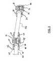
- FIG. 1is a perspective view of an embodiment of the invention including several bodies interconnected to one another and attached to surgical screws (note that the attachment systems shown have not yet been fixed in place relative to one another in this view);
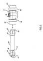
- FIG. 2illustrates a linking rod assembly and a coupler in accordance with an embodiment of the invention
- FIG. 3is a sectioned view of the linking rod assembly and coupler of FIG. 2 , shown attached to a second linking rod and second, end coupler;
- FIG. 4Ais a partially exploded view of the system of FIG. 1 ;
- FIG. 4Billustrates the system of FIG. 4A , with the couplers moved into position atop the surgical screws, and with the center coupler fixed to the center surgical screw;
- FIG. 4Cillustrates the system of FIG. 4A with each of the couplers fixed to their respective surgical screws
- FIG. 4Dillustrates the system of FIG. 4A with each of the couplers fixed to their respective counterparts.
- the term “substantially”refers to the complete or nearly complete extent or degree of an action, characteristic, property, state, structure, item, or result.
- an object that is “substantially” enclosedwould mean that the object is either completely enclosed or nearly completely enclosed.
- the exact allowable degree of deviation from absolute completenessmay in some cases depend on the specific context. However, generally speaking the nearness of completion will be so as to have the same overall result as if absolute and total completion were obtained.
- the use of “substantially”is equally applicable when used in a negative connotation to refer to the complete or near complete lack of an action, characteristic, property, state, structure, item, or result.
- a composition that is “substantially free of an ingredient or elementmay still actually contain such item as long as there is no measurable effect thereof.
- the terms “attached,” “coupled,” fixed,” etc.can be used to describe a condition in which two or more components are coupled to one another in such a manner that they function as intended: that is, the force required to uncouple the components is sufficiently large such that the components will remain attached to one another during the service for which they were designed. Unless indicated to the contrary, such “coupled” components can be separable if sufficient force is applied to the components.
- componentsare elastically fixed or coupled to one another and will remain fixed during the useful life of the product for which they are designed; however, they may be uncoupled from one another using an appropriate level of force (applied in an appropriate manner and location), and will return to an original configuration (e.g., a condition, state, shape, size, etc.), which existed prior to the components being coupled to one another.
- an area within a construct bodyis described as having a “decreased diameter,” it is to be understood that the area described includes a diameter that is smaller than adjacent areas (either on one or both sides of the area of decreased diameter).
- an area within a boremay have a decreased diameter as compared to other portions of the bore.
- the area of decreased diameter within the borewill appear (although possibly not to the human eye) as an inner “rib,” or raised portion, having a smaller diameter than adjacent portions.
- bodycan be used herein to refer to a variety of components of a surgical construct. For example, several components are illustrated in FIG. 1 , including connecting rods 12 a , 12 b , “T” coupler 14 , end couplers 16 a , 16 b , etc. Each of these components can be included within the scope of the meaning of the term “body.”
- surgical screws 18 a , 18 b , 18 care not referred to herein as “bodies;” however, a specific discussion of one or more embodiments may dictate otherwise, as would be appreciated by one of ordinary skill in the art having possession of this disclosure.
- interference fitshall be interpreted broadly as including the joining of any two mating parts such that one or the other (or both) parts slightly deviate in size from their nominal dimension, thereby deforming such part slightly, each being compressed, the interface between two parts creating a union of extremely high friction.
- the word “interference”refers to the fact that one part slightly interferes with the space that the other is occupying in its nominal dimension.
- interference fitcan be configured to require at least about 800 pounds of force to remove a male member from a female member.
- interference fitcan be configured to require at least about 400 pounds of force to remove a male member from a female member.
- interference fitcan be configured to require at least about 1200 pounds of force to remove a male member from a female member.
- the term “about”is used to provide flexibility to a numerical range endpoint by providing that a given value may be “a little above” or “a little below” the endpoint.
- Numerical datamay be expressed or presented herein in a range format. It is to be understood that such a range format is used merely for convenience and brevity and thus should be interpreted flexibly to include not only the numerical values explicitly recited as the limits of the range, but also to include all the individual numerical values or sub-ranges encompassed within that range as if each numerical value and sub-range is explicitly recited.
- a numerical range of “about 1 to about 5”should be interpreted to include not only the explicitly recited values of about 1 to about 5, but also include individual values and sub-ranges within the indicated range.
- included in this numerical rangeare individual values such as 2, 3, and 4 and sub-ranges such as from 1-3, from 2-4, and from 3-5, etc., as well as 1, 2, 3, 4, and 5, individually.
- the present inventionrelates generally to surgical construct systems that can include a variety of coupling assemblies that are used to connect a variety of surgical screws.
- the surgical screwsgenerally include a threaded portion which is used to implant the screws into the body of a patient, often into bone of the patient.
- the present systemis suitable for use with a variety of orthopedic rod placement devices, hooks, and/or surgical screws, including, but not limited to, pedicle screws and orthopedic rods used in spinal surgery.
- a coupling assembly 10is provided.
- the assemblyincludes three surgical screws 18 a , 18 b and 18 c .
- the screwscan be interconnected to one another by way of end couplers 16 a , 16 b , “T” coupler 14 and rod connectors 12 a , 12 b .
- the assemblycan be used in a variety of surgical applications, including, but not limited to, spinal implant surgeries.
- the present inventionprovides robust and durable coupling assemblies that have a smaller profile with fewer components and greater ease of assembly with more surgical options than prior art devices. It is believed that the embodiments, collectively and/or individually, represent an unexpected advance in the field and will enable physicians to more easily adjust and/or accommodate for various factors.
- connector rod body 12 aincludes at least one male member 20 (two are shown, one on each end of the connector rod).
- “T” coupler body 14can include one or more female members 22 that can include an internal bore (best seen at 24 in FIG. 3 ).
- the internal bore of the female member and the male membercan be cooperatively sized and shaped such that the male member fits easily within the female member.
- the male member 20includes a raised portion 26 that can be formed on or attached to the male member.
- the internal bore 24 of the female membercan include an area of decreased diameter associated therewith.
- the area of decreased diameter ( 25 in FIG. 3 )while not always event to the human eye, is created in the embodiment shown in FIG. 3 immediately beneath a cinch band 28 .
- the cinch bandfits about an outer portion of the female member and applies a compressive force to the female member. This compressive force is translated though the barrel or cylinder of the female member such that the inner bore is slightly decreased in diameter beneath the cinch band.
- the raised portion 26 of the male member 20 and the area of decreased diameter 25 within the bore of the female member 22are positioned adjacent one another and an interference fit is created between the two bodies.
- This conditionis shown by the displaced cinch band 28 ′ in FIG. 3 .
- the cinch band 28is moveable or slidable along the outer portion of the female member 22 .
- the cinch bandis fitted about the outer portion of the female member such that a force of about 800 pounds is required to move the cinch band along the outer portion. Since the position of the cinch band is adjustable, the location at which the male member and the female member are coupled to one another can be adjusted. That is, the raised portion of the male member can be positioned in a variety of locations within the bore of the female member, after which the cinch band can be positioned over the raised portion to fix or attach or couple the bodies one to another.
- the area of decreased diameter 25 within the bore 24 of the female member 22can be accomplished in a number of manners.
- the area of decreased diametercan be a permanent feature formed within the bore.
- the cinch bandcan be very loosely fitted about the outer portion of the female member (such that almost no force is required to move it along the length of the outer portion), and it can be clamped into position about the outer portion where desired.
- the cinch bandcan be formed from a shape memory alloy that can be activated by a change in temperature or by stress. A variety of other methods can be used to accomplish this result, so long as the resultant force applied by the cinch band is sufficient to create the area of decreased diameter within the bore of the female member.
- the raised portion 26 of the male member 20is moveably attached to the male member so as to be selectively positionable along at least a portion of a length of the male member. This provides further adjustability to the system, allowing a doctor to “fine tune” the position where the two bodies 12 a and 14 (in this example) are coupled to one another, to allow precise adjustments to the construct.
- the raised portioncomprises a band that is snugly fitted about the male member such that the band generally remains in position during the procedure, but can be relatively easily moved by a doctor: even allowing adjustments by finger force prior to inserting the male member within the female member.
- the raised portion 26can include a generally spherical outer contour that allows the coupling rod body 12 a to be rotated relative to the “T” coupler 14 (or other body) to provide easy adjustments in angle between bodies.
- the leftmost connector rod 12 ais substantially in-line with the leftmost inner bore of “T” coupler 14
- the rightmost connector rod 12 bcan be positioned at a significant angle relative to the axis of the rightmost inner bore of the “T” coupler.
- the present systemallows the connector rods 12 a , 12 b to be easily and securely coupled, via an interference fit, to the “T” coupler.
- the raised portion 26allows for translational adjustments (as it can be slid along the male portion) and rotational adjustments (as it can be rotated within the bore of the female member).
- the cinch band 28 configurationallows for further translational adjustment, as it can be cinched about the raised portion in a variety of positions along the length of the female member.
- the raised portion 26can include one or more slots ( 27 in FIG. 2 ) formed therein that allow the spherical band to more easily compress beneath the area of decreased diameter associated with the female member to provide the interference fit between the first and second bodies.
- the slots 27extend from one edge of the band and terminate slightly before reaching the other edge of the band.
- the slotsare also offset from one another (e.g., they alternate beginning on one edge of the band), so that the band is formed from a monolithic piece of material that is substantially symmetrical about an equator of the band.
- the male member 20 of the connector rod body 12 acan include a retaining lip 30 that retains the moveable raised portion (or band) 26 on the male member shaft, to prevent the band from falling off of the shaft during initial assembly of the construct. Due to the flexibility provided to the band by the slots 27 , the band can expand slightly in the configuration shown in FIG. 2 to fit over the retaining lip while the male member is outside of the bore 24 of the female member. However, once positioned inside the bore of the female member, the band can slide but cannot expand enough to pass beyond the retaining lip 30 . Thus, there is little to no risk that the band can slide off the male member during installation of the construct.
- the various bodies 12 a , 16 a , 14 , etc.can be coupled to one another by an interference fit that effectively locks the components in position relative to one another once implanted into a patient.
- the interference fitcan be created elastically. In this manner, all of the components utilized can be disengaged (or uncoupled) from one another, and will return to their original condition (e.g., their original shape, dimensions, etc.).
- the present systemcan be disassembled and used again if, for example, the surgeon wishes to readjust the various components after installation, or if later surgery requires dismantling, adjustment or additions to the system.
- One or more of the bodies 12 a , 14 , 16 a , 16 b , 16 c , etc.can include a receptacle ( 32 in FIG. 3 , for example) formed therein that can be operable to receive a head portion of a surgical screw to allow implantation of the assembly within a body of a patient.
- a ball socket 34can be positioned within the receptacle 32 to facilitate a secure connection to the head of the surgical screw.
- FIG. 3illustrates one manner in which the ball socket 34 can be coupled to the screw head.
- a threaded set screw 36can be positioned above the ball socket.
- the set screwcan be turned downward to compress and lock the ball socket over the head of the surgical screw. See, for example, FIG. 4B , where the center surgical screw 18 b is locked into position within “T” coupler 14 , while the outer two surgical screws have not yet been locked into position (the set screws on these couplers have not yet been threaded down to force the ball socket into position around the surgical screws).
- set screw 36While set screw 36 , shown in most of the embodiments, remains in place over the ball socket 34 , it is to be understood that a removable set screw could also be utilized. This is due to the design of the ball socket, which becomes locked in place over the head of the surgical screws and remains in place unless it becomes necessary to remove the body from the surgical screw. In addition, a tool or implement could be used to lock the ball socket in place over the head of the surgical screw, and no set screw would be required.
- the present inventionadvantageously provides a surgeon with a great deal of latitude when deciding the order in which the various components of the system will be coupled one to another.
- the sequence of lockingcan be varied depending on what the surgeon is attempting to do to manipulate bone position.
- the surgeonmay choose a unique sequence of locking rods-to-couplers or couplers-to-bone screws for each of several surgical maneuvers (e.g. in spinal surgery he might employ unique sequences to reduce a spondylolisthesis, correct scoliosis, change lordosis, manipulate disc space height, etc.).
- the novel segmentation of rods and unique mechanism for lockingsimplify surgical correction of bones.
- FIGS. 4A through 4Dillustrate one exemplary manner of attaching a series of connector rods ( 12 a , 12 b ) coupled to a series of bodies ( 16 a , 14 and 16 b ) which will be attached to a series of surgical screws ( 18 a , 18 b and 18 c ).
- the sequencebegins by inserting male portions of connector rods 12 a , 12 b into female bores of connectors (or bodies) 16 a , 14 and 16 b . Each body can then be lowered into place over its respective surgical screw. Note that, in this example, none of the components are fixed relative to one another immediately after the bodies are lowered onto the surgical screws.
- FIG. 4Bit can be seen that “T” coupler 14 has been attached or fixed to surgical screw 18 b , but none of the remaining components have been fixed.
- FIG. 4Cit can be seen that all of the bodies ( 16 a , 14 and 16 b ) have been fixed or coupled to their respective surgical screws ( 18 a , 18 b and 18 c , respectively). However, none of the bodies have yet been fixed to the connector rods 12 a , 12 b .
- FIG. 4Dit can be seen that each of the cinch bands 26 has been moved into its “locked” position (as shown by directional indicators 29 ) such that all components of the construct are now rigidly fixed or coupled one to another.
- a method of coupling portions of a surgical construct to one anotherincluding: obtaining a first body and a second body, one of the first body and the second body including a male member and an other of the first body and the second body including a female member, the male member being sized and shaped to be received within the female member and the female member having an internal bore sized and shaped to receive the male member therein; positioning a raised portion formed on or attached to the male member within the internal bore of the female member; and creating an area of decreased diameter within the internal bore of the female member about or around the raised portion of the male member to thereby couple the first body and the second body to one another by an interference fit.
- a method of implanting a coupling assembly within a patientincluding: attaching one of a first body and a second body to a first surgical screw, one of the first body and the second body including a male member and an other of the first body and the second body including a female member, the male member being sized and shaped to be received within the female member and the female member having an internal bore sized and shaped to receive the male member therein; positioning a raised portion formed on or attached to the male member within the internal bore of the female member; and creating an area of decreased diameter within the internal bore of the female member about or around the raised portion of the male member to thereby couple the first body and the second body to one another by an interference fit.
Landscapes
- Health & Medical Sciences (AREA)
- Orthopedic Medicine & Surgery (AREA)
- Life Sciences & Earth Sciences (AREA)
- Surgery (AREA)
- Neurology (AREA)
- Heart & Thoracic Surgery (AREA)
- Engineering & Computer Science (AREA)
- Biomedical Technology (AREA)
- Nuclear Medicine, Radiotherapy & Molecular Imaging (AREA)
- Medical Informatics (AREA)
- Molecular Biology (AREA)
- Animal Behavior & Ethology (AREA)
- General Health & Medical Sciences (AREA)
- Public Health (AREA)
- Veterinary Medicine (AREA)
- Prostheses (AREA)
- Surgical Instruments (AREA)
Abstract
Description
- Priority is claimed of U.S. Provisional Patent Application Ser. No. 61/478,808, filed Apr. 25, 2011, which is hereby incorporated herein by reference in its entirety.
- This application is related to U.S. patent application Ser. No. 12/711,131, filed Feb. 23, 2010, which is hereby incorporated herein by reference in its entirety.
- 1. Field of the Invention
- The present invention relates generally to the field of coupling systems for use in surgical implants. More particularly, the present invention relates to such systems for use in orthopedic rod fixation systems.
- 2. Related Art
- Bone stabilization/fixation devices to align or position bones have been used for some time. Such devices have been used to align or position specific vertebrae, or a specific region of the spine. Typically, such devices utilize a coupling assembly to connect or link two or more surgical screws and/or pedicle screws together to stabilize the bone and/or joint around which the screws are fixed. Conventional coupling assemblies are typically comprised of a relatively rigid member, such as a plate or a rod, that is used to couple or join adjacent structures or parts of the anatomy. Once the coupled structures are spatially fixed in position, surgical procedures can be completed and healing can proceed.
- The present inventor has found, however, that such conventional surgical and/or pedicle screw coupling systems have several drawbacks. For example, such systems are rather large and bulky, which can result in increased tissue damage in and around the surgical site, resulting both from installation of the coupling system during surgery and from implant induced, post-operative tissue irritation and erosion. The relative bulk of prior art devices can be particularly troublesome in supra-fascial applications.
- Some prior art coupling systems have a rod-receiving device that is delivered to the surgeon already coupled or attached to the head of the surgical screw, which poses two challenges: 1) this prevents certain surgical maneuvers (e.g. placing the screws prior to interbody work); and, 2) increases the carrying cost of the inventory. Furthermore, traditional coupling systems do not allow for varying the rod stiffness along a multi-segmented construct; certain indications may require a stiff rod over one segment and a flexible rod over another.
- Further, traditional systems inherently possess an inability to easily extend a fusion: e.g., in a revision procedure, the existing rod would need to be either completely removed and replaced with a new rod or cut in vivo. In addition, some of the prior art coupling systems include locking components (e.g., set screws and the like) that must all be carefully assembled together during the surgical procedure. Further, many traditional surgical screw system designs complicate or even preclude the ability to be placed percutaneously over a guide wire, which makes these systems more difficult to install and maneuver during surgical procedures, including minimally invasive procedures.
- Furthermore, many prior art devices require that the rod be attached to the coupling device after the screw is inserted in the bone, which can be disadvantageous at times, whereas the option to assemble the rod to the coupling device outside the wound may prove valuable. Also, existing coupling systems often necessitate simultaneous locking of all components, which prevents the ability to properly compress a coupling system along the rod because the angle relative to the surgical screw would change.
- Furthermore, predicate technology necessitates bending of the rod for multi-segmented constructs. Rod bending is not only cumbersome to perform, but invariably results in an unintended stress applied to the bones.
- In accordance with one aspect of the invention, a coupling assembly for use in surgical constructs is provided, including a first body and a second body. One of the first body and the second body includes a male member and an other of the first body and the second body includes a female member. The male member is sized and shaped to be received within the female member and the female member has an internal bore sized and shaped to receive the male member therein. A raised portion can be formed on or attached to the male member. An area of decreased diameter can be associated with the internal bore of the female member. The first and second bodies are coupleable to one another by an interference fit when a portion of the male member is positioned within an area of smaller diameter associated with the internal bore of the female member.
- In accordance with another aspect of the invention, a coupling assembly for use in surgical constructs is provided, including a first body and a second body. One of the first body and the second body can include a male member and an other of the first body and the second body can include a female member. The male member is sized and shaped to be received within the female member and the female member can have an internal bore sized and shaped to receive the male member therein. A raised portion can be formed on or attached to the male member. A cinch band can be applied to an outer portion of the female member that applies a compressive force to the female member to create an area of decreased diameter within the internal bore of the female member. The first and second bodies can be coupleable to one another by an interference fit when the raised portion of the male member is positioned within the area of decreased diameter in the internal bore of the female member.
- In accordance with another aspect of the invention, a method of coupling portions of a surgical construct to one another is provided, including: obtaining a first body and a second body, one of the first body and the second body including a male member and an other of the first body and the second body including a female member, the male member being sized and shaped to be received within the female member and the female member having an internal bore sized and shaped to receive the male member therein; positioning a raised portion formed on or attached to the male member within the internal bore of the female member; and creating an area of decreased diameter within the internal bore of the female member about or around the raised portion of the male member to thereby couple the first body and the second body to one another by an interference fit.
- In accordance with another aspect of the invention, a method of implanting a coupling assembly within a patient is provided, including: attaching one of a first body and a second body to a first surgical screw, one of the first body and the second body including a male member and an other of the first body and the second body including a female member, the male member being sized and shaped to be received within the female member and the female member having an internal bore sized and shaped to receive the male member therein; positioning a raised portion formed on or attached to the male member within the internal bore of the female member; and creating an area of decreased diameter within the internal bore of the female member about or around the raised portion of the male member to thereby couple the first body and the second body to one another by an interference fit.
- Additional features and advantages of the invention will be apparent from the detailed description which follows, taken in conjunction with the accompanying drawings, which together illustrate, by way of example, features of the invention.
- The following drawings illustrate exemplary embodiments for carrying out the invention. Like reference numerals refer to like parts in different views or embodiments of the present invention in the drawings.
FIG. 1 is a perspective view of an embodiment of the invention including several bodies interconnected to one another and attached to surgical screws (note that the attachment systems shown have not yet been fixed in place relative to one another in this view);FIG. 2 illustrates a linking rod assembly and a coupler in accordance with an embodiment of the invention;FIG. 3 is a sectioned view of the linking rod assembly and coupler ofFIG. 2 , shown attached to a second linking rod and second, end coupler;FIG. 4A is a partially exploded view of the system ofFIG. 1 ;FIG. 4B illustrates the system ofFIG. 4A , with the couplers moved into position atop the surgical screws, and with the center coupler fixed to the center surgical screw;FIG. 4C illustrates the system ofFIG. 4A with each of the couplers fixed to their respective surgical screws; andFIG. 4D illustrates the system ofFIG. 4A with each of the couplers fixed to their respective counterparts.- Reference will now be made to the exemplary embodiments illustrated in the drawings, and specific language will be used herein to describe the same. It will nevertheless be understood that no limitation of the scope of the invention is thereby intended. Alterations and further modifications of the inventive features illustrated herein, and additional applications of the principles of the inventions as illustrated herein, which would occur to one skilled in the relevant art and having possession of this disclosure, are to be considered within the scope of the invention.
- As used herein, the singular forms “a” and “the” can include plural referents unless the context clearly dictates otherwise. Thus, for example, reference to “a coupler” can include one or more of such couplers.
- As used herein, the term “substantially” refers to the complete or nearly complete extent or degree of an action, characteristic, property, state, structure, item, or result. As an arbitrary example, an object that is “substantially” enclosed would mean that the object is either completely enclosed or nearly completely enclosed. The exact allowable degree of deviation from absolute completeness may in some cases depend on the specific context. However, generally speaking the nearness of completion will be so as to have the same overall result as if absolute and total completion were obtained. The use of “substantially” is equally applicable when used in a negative connotation to refer to the complete or near complete lack of an action, characteristic, property, state, structure, item, or result. As another arbitrary example, a composition that is “substantially free of an ingredient or element may still actually contain such item as long as there is no measurable effect thereof.
- As used herein, the terms “attached,” “coupled,” fixed,” etc., can be used to describe a condition in which two or more components are coupled to one another in such a manner that they function as intended: that is, the force required to uncouple the components is sufficiently large such that the components will remain attached to one another during the service for which they were designed. Unless indicated to the contrary, such “coupled” components can be separable if sufficient force is applied to the components. In some aspects of the invention, components are elastically fixed or coupled to one another and will remain fixed during the useful life of the product for which they are designed; however, they may be uncoupled from one another using an appropriate level of force (applied in an appropriate manner and location), and will return to an original configuration (e.g., a condition, state, shape, size, etc.), which existed prior to the components being coupled to one another.
- As used herein, when an area within a construct body is described as having a “decreased diameter,” it is to be understood that the area described includes a diameter that is smaller than adjacent areas (either on one or both sides of the area of decreased diameter). For example, an area within a bore may have a decreased diameter as compared to other portions of the bore. In some embodiments, the area of decreased diameter within the bore will appear (although possibly not to the human eye) as an inner “rib,” or raised portion, having a smaller diameter than adjacent portions.
- The term “body” can be used herein to refer to a variety of components of a surgical construct. For example, several components are illustrated in
FIG. 1 , including connectingrods coupler 14,end couplers surgical screws - As used herein, the term “interference fit” shall be interpreted broadly as including the joining of any two mating parts such that one or the other (or both) parts slightly deviate in size from their nominal dimension, thereby deforming such part slightly, each being compressed, the interface between two parts creating a union of extremely high friction. The word “interference” refers to the fact that one part slightly interferes with the space that the other is occupying in its nominal dimension. In one aspect of the invention, interference fit can be configured to require at least about 800 pounds of force to remove a male member from a female member. In one aspect of the invention, interference fit can be configured to require at least about 400 pounds of force to remove a male member from a female member. In one aspect of the invention, interference fit can be configured to require at least about 1200 pounds of force to remove a male member from a female member.
- As used herein, the term “about” is used to provide flexibility to a numerical range endpoint by providing that a given value may be “a little above” or “a little below” the endpoint.
- As used herein, a plurality of items, structural elements, compositional elements, and/or materials may be presented in a common list for convenience. However, these lists should be construed as though each member of the list is individually identified as a separate and unique member. Thus, no individual member of such list should be construed as a de facto equivalent of any other member of the same list solely based on their presentation in a common group without indications to the contrary.
- Numerical data may be expressed or presented herein in a range format. It is to be understood that such a range format is used merely for convenience and brevity and thus should be interpreted flexibly to include not only the numerical values explicitly recited as the limits of the range, but also to include all the individual numerical values or sub-ranges encompassed within that range as if each numerical value and sub-range is explicitly recited. As an illustration, a numerical range of “about 1 to about 5” should be interpreted to include not only the explicitly recited values of about 1 to about 5, but also include individual values and sub-ranges within the indicated range. Thus, included in this numerical range are individual values such as 2, 3, and 4 and sub-ranges such as from 1-3, from 2-4, and from 3-5, etc., as well as 1, 2, 3, 4, and 5, individually.
- This same principle applies to ranges reciting only one numerical value as a minimum or a maximum. Furthermore, such an interpretation should apply regardless of the breadth of the range or the characteristics being described.
- The present invention relates generally to surgical construct systems that can include a variety of coupling assemblies that are used to connect a variety of surgical screws. The surgical screws generally include a threaded portion which is used to implant the screws into the body of a patient, often into bone of the patient. The present system is suitable for use with a variety of orthopedic rod placement devices, hooks, and/or surgical screws, including, but not limited to, pedicle screws and orthopedic rods used in spinal surgery.
- As shown specifically in
FIGS. 1 and 2 , in one exemplary embodiment of the invention, acoupling assembly 10 is provided. In this aspect of the invention, the assembly includes threesurgical screws end couplers coupler 14 androd connectors - Turning to
FIGS. 2 and 3 , specific aspects of one embodiment of the invention are shown in greater detail. In this embodiment,connector rod body 12aincludes at least one male member20 (two are shown, one on each end of the connector rod). “T”coupler body 14 can include one or morefemale members 22 that can include an internal bore (best seen at24 inFIG. 3 ). The internal bore of the female member and the male member can be cooperatively sized and shaped such that the male member fits easily within the female member. - Coupling or attaching of the
male member 20 to thefemale member 22 can be accomplished in a number of manners. In one embodiment of the invention, the male member includes a raisedportion 26 that can be formed on or attached to the male member. The internal bore24 of the female member can include an area of decreased diameter associated therewith. The area of decreased diameter (25 inFIG. 3 ), while not always event to the human eye, is created in the embodiment shown inFIG. 3 immediately beneath acinch band 28. In this aspect, the cinch band fits about an outer portion of the female member and applies a compressive force to the female member. This compressive force is translated though the barrel or cylinder of the female member such that the inner bore is slightly decreased in diameter beneath the cinch band. - To couple the
connector rod body 12ato the “T”coupler body 14, the raisedportion 26 of themale member 20 and the area of decreaseddiameter 25 within the bore of thefemale member 22 are positioned adjacent one another and an interference fit is created between the two bodies. This condition is shown by the displacedcinch band 28′ inFIG. 3 . Thus, in this embodiment, thecinch band 28 is moveable or slidable along the outer portion of thefemale member 22. In one example, the cinch band is fitted about the outer portion of the female member such that a force of about 800 pounds is required to move the cinch band along the outer portion. Since the position of the cinch band is adjustable, the location at which the male member and the female member are coupled to one another can be adjusted. That is, the raised portion of the male member can be positioned in a variety of locations within the bore of the female member, after which the cinch band can be positioned over the raised portion to fix or attach or couple the bodies one to another. - While a sliding
cinch band 28 is shown in the figures, it is to be understood that the area of decreaseddiameter 25 within thebore 24 of thefemale member 22 can be accomplished in a number of manners. In one aspect of the invention, the area of decreased diameter can be a permanent feature formed within the bore. In another aspect, the cinch band can be very loosely fitted about the outer portion of the female member (such that almost no force is required to move it along the length of the outer portion), and it can be clamped into position about the outer portion where desired. In yet another aspect, the cinch band can be formed from a shape memory alloy that can be activated by a change in temperature or by stress. A variety of other methods can be used to accomplish this result, so long as the resultant force applied by the cinch band is sufficient to create the area of decreased diameter within the bore of the female member. - In the aspect of the invention shown in
FIGS. 2 and 3 , the raisedportion 26 of themale member 20 is moveably attached to the male member so as to be selectively positionable along at least a portion of a length of the male member. This provides further adjustability to the system, allowing a doctor to “fine tune” the position where the twobodies 12aand14 (in this example) are coupled to one another, to allow precise adjustments to the construct. In the embodiment shown, the raised portion comprises a band that is snugly fitted about the male member such that the band generally remains in position during the procedure, but can be relatively easily moved by a doctor: even allowing adjustments by finger force prior to inserting the male member within the female member. - The raised
portion 26 can include a generally spherical outer contour that allows thecoupling rod body 12ato be rotated relative to the “T” coupler14 (or other body) to provide easy adjustments in angle between bodies. As shown, for example, inFIG. 3 , theleftmost connector rod 12ais substantially in-line with the leftmost inner bore of “T”coupler 14, while therightmost connector rod 12bcan be positioned at a significant angle relative to the axis of the rightmost inner bore of the “T” coupler. In each case, the present system allows theconnector rods portion 26 allows for translational adjustments (as it can be slid along the male portion) and rotational adjustments (as it can be rotated within the bore of the female member). Also, thecinch band 28 configuration allows for further translational adjustment, as it can be cinched about the raised portion in a variety of positions along the length of the female member. - While not so required, the raised
portion 26 can include one or more slots (27 inFIG. 2 ) formed therein that allow the spherical band to more easily compress beneath the area of decreased diameter associated with the female member to provide the interference fit between the first and second bodies. In the embodiment shown, theslots 27 extend from one edge of the band and terminate slightly before reaching the other edge of the band. The slots are also offset from one another (e.g., they alternate beginning on one edge of the band), so that the band is formed from a monolithic piece of material that is substantially symmetrical about an equator of the band. - As shown in
FIG. 2 , themale member 20 of theconnector rod body 12acan include a retaininglip 30 that retains the moveable raised portion (or band)26 on the male member shaft, to prevent the band from falling off of the shaft during initial assembly of the construct. Due to the flexibility provided to the band by theslots 27, the band can expand slightly in the configuration shown inFIG. 2 to fit over the retaining lip while the male member is outside of thebore 24 of the female member. However, once positioned inside the bore of the female member, the band can slide but cannot expand enough to pass beyond the retaininglip 30. Thus, there is little to no risk that the band can slide off the male member during installation of the construct. - In the system shown, the
various bodies cinch band 28, the interference fit can be created elastically. In this manner, all of the components utilized can be disengaged (or uncoupled) from one another, and will return to their original condition (e.g., their original shape, dimensions, etc.). Thus, the present system can be disassembled and used again if, for example, the surgeon wishes to readjust the various components after installation, or if later surgery requires dismantling, adjustment or additions to the system. - One or more of the
bodies FIG. 3 , for example) formed therein that can be operable to receive a head portion of a surgical screw to allow implantation of the assembly within a body of a patient. In some embodiments of the invention, aball socket 34 can be positioned within thereceptacle 32 to facilitate a secure connection to the head of the surgical screw.FIG. 3 illustrates one manner in which theball socket 34 can be coupled to the screw head. In this example, a threadedset screw 36 can be positioned above the ball socket. Once the head of the surgical screw (not shown inFIG. 3 ) is inserted into the ball socket, the set screw can be turned downward to compress and lock the ball socket over the head of the surgical screw. See, for example,FIG. 4B , where the centersurgical screw 18bis locked into position within “T”coupler 14, while the outer two surgical screws have not yet been locked into position (the set screws on these couplers have not yet been threaded down to force the ball socket into position around the surgical screws). - While
set screw 36, shown in most of the embodiments, remains in place over theball socket 34, it is to be understood that a removable set screw could also be utilized. This is due to the design of the ball socket, which becomes locked in place over the head of the surgical screws and remains in place unless it becomes necessary to remove the body from the surgical screw. In addition, a tool or implement could be used to lock the ball socket in place over the head of the surgical screw, and no set screw would be required. - The present invention advantageously provides a surgeon with a great deal of latitude when deciding the order in which the various components of the system will be coupled one to another. Thus, the sequence of locking can be varied depending on what the surgeon is attempting to do to manipulate bone position. Specifically, the surgeon may choose a unique sequence of locking rods-to-couplers or couplers-to-bone screws for each of several surgical maneuvers (e.g. in spinal surgery he might employ unique sequences to reduce a spondylolisthesis, correct scoliosis, change lordosis, manipulate disc space height, etc.). The novel segmentation of rods and unique mechanism for locking simplify surgical correction of bones.
FIGS. 4A through 4D illustrate one exemplary manner of attaching a series of connector rods (12a,12b) coupled to a series of bodies (16a,14 and16b) which will be attached to a series of surgical screws (18a,18band18c). InFIG. 4A , the sequence begins by inserting male portions ofconnector rods - In
FIG. 4B , it can be seen that “T”coupler 14 has been attached or fixed tosurgical screw 18b, but none of the remaining components have been fixed. InFIG. 4C , it can be seen that all of the bodies (16a,14 and16b) have been fixed or coupled to their respective surgical screws (18a,18band18c, respectively). However, none of the bodies have yet been fixed to theconnector rods FIG. 4D , it can be seen that each of thecinch bands 26 has been moved into its “locked” position (as shown by directional indicators29) such that all components of the construct are now rigidly fixed or coupled one to another. - One of ordinary skill in the art, having possession of this disclosure, could readily appreciate that a different order or fixing the various components could be utilized if the surgeon wished to accomplish a different result.
- In addition to the apparatus discussed above, the present invention also provides various methods of coupling components of surgical constructs, and implanting surgical constructs. In one embodiment, a method of coupling portions of a surgical construct to one another is provided, including: obtaining a first body and a second body, one of the first body and the second body including a male member and an other of the first body and the second body including a female member, the male member being sized and shaped to be received within the female member and the female member having an internal bore sized and shaped to receive the male member therein; positioning a raised portion formed on or attached to the male member within the internal bore of the female member; and creating an area of decreased diameter within the internal bore of the female member about or around the raised portion of the male member to thereby couple the first body and the second body to one another by an interference fit.
- In another aspect, a method of implanting a coupling assembly within a patient is provided, including: attaching one of a first body and a second body to a first surgical screw, one of the first body and the second body including a male member and an other of the first body and the second body including a female member, the male member being sized and shaped to be received within the female member and the female member having an internal bore sized and shaped to receive the male member therein; positioning a raised portion formed on or attached to the male member within the internal bore of the female member; and creating an area of decreased diameter within the internal bore of the female member about or around the raised portion of the male member to thereby couple the first body and the second body to one another by an interference fit.
- It is to be understood that the above-referenced arrangements are illustrative of the application for the principles of the present invention. Numerous modifications and alternative arrangements can be devised without departing from the spirit and scope of the present invention while the present invention has been shown in the drawings and described above in connection with the exemplary embodiments(s) of the invention. It will be apparent to those of ordinary skill in the art that numerous modifications can be made without departing from the principles and concepts of the invention as set forth in the examples.
Claims (21)
Priority Applications (4)
| Application Number | Priority Date | Filing Date | Title |
|---|---|---|---|
| US13/455,854US8894687B2 (en) | 2011-04-25 | 2012-04-25 | Coupling system for surgical construct |
| US14/060,753US20170143377A9 (en) | 2011-04-25 | 2013-10-23 | Surgical construct coupling system |
| US14/757,080US9801667B2 (en) | 2007-12-07 | 2015-11-16 | Instruments, tools, and methods for presson pedicle screws |
| US14/998,660US20170020571A1 (en) | 2007-12-07 | 2016-01-28 | Additive manufacturing for spinal implants |
Applications Claiming Priority (2)
| Application Number | Priority Date | Filing Date | Title |
|---|---|---|---|
| US201161478808P | 2011-04-25 | 2011-04-25 | |
| US13/455,854US8894687B2 (en) | 2011-04-25 | 2012-04-25 | Coupling system for surgical construct |
Related Child Applications (1)
| Application Number | Title | Priority Date | Filing Date |
|---|---|---|---|
| US14/060,753Continuation-In-PartUS20170143377A9 (en) | 2007-12-07 | 2013-10-23 | Surgical construct coupling system |
Publications (2)
| Publication Number | Publication Date |
|---|---|
| US20130110170A1true US20130110170A1 (en) | 2013-05-02 |
| US8894687B2 US8894687B2 (en) | 2014-11-25 |
Family
ID=46044468
Family Applications (1)
| Application Number | Title | Priority Date | Filing Date |
|---|---|---|---|
| US13/455,854ActiveUS8894687B2 (en) | 2007-12-07 | 2012-04-25 | Coupling system for surgical construct |
Country Status (2)
| Country | Link |
|---|---|
| US (1) | US8894687B2 (en) |
| EP (1) | EP2517660B1 (en) |
Cited By (4)
| Publication number | Priority date | Publication date | Assignee | Title |
|---|---|---|---|---|
| US20130261668A1 (en)* | 2010-12-03 | 2013-10-03 | Zimmer Spine | Rod holding device |
| US20140114357A1 (en)* | 2011-04-25 | 2014-04-24 | Nexus Spine, L.L.C. | Surgical construct coupling system |
| US20170020571A1 (en)* | 2007-12-07 | 2017-01-26 | Nexus Spine, LLC | Additive manufacturing for spinal implants |
| US11439439B2 (en)* | 2012-03-01 | 2022-09-13 | Globus Medical, Inc. | Closed-head polyaxial and monaxial screws |
Families Citing this family (1)
| Publication number | Priority date | Publication date | Assignee | Title |
|---|---|---|---|---|
| US11571244B2 (en)* | 2019-05-22 | 2023-02-07 | Nuvasive, Inc. | Posterior spinal fixation screws |
Family Cites Families (121)
| Publication number | Priority date | Publication date | Assignee | Title |
|---|---|---|---|---|
| US3945053A (en) | 1973-03-05 | 1976-03-23 | Purdue Research Foundation | Rolling contact prosthetic knee joint |
| US5772661A (en) | 1988-06-13 | 1998-06-30 | Michelson; Gary Karlin | Methods and instrumentation for the surgical correction of human thoracic and lumbar spinal disease from the antero-lateral aspect of the spine |
| US5415661A (en) | 1993-03-24 | 1995-05-16 | University Of Miami | Implantable spinal assist device |
| US5405408A (en) | 1993-05-14 | 1995-04-11 | Pitkin; Mark R. | Artificial knee having dual flexion action during locomotion |
| WO1995010238A1 (en) | 1993-10-08 | 1995-04-20 | Chaim Rogozinski | Spinal treatment apparatus and method including multi-directional attachment member |
| US7494507B2 (en) | 2000-01-30 | 2009-02-24 | Diamicron, Inc. | Articulating diamond-surfaced spinal implants |
| US5733285A (en) | 1995-07-13 | 1998-03-31 | Fastenetix, Llc | Polyaxial locking mechanism |
| US5964760A (en) | 1996-10-18 | 1999-10-12 | Spinal Innovations | Spinal implant fixation assembly |
| US5776135A (en) | 1996-12-23 | 1998-07-07 | Third Millennium Engineering, Llc | Side mounted polyaxial pedicle screw |
| US7306628B2 (en) | 2002-10-29 | 2007-12-11 | St. Francis Medical Technologies | Interspinous process apparatus and method with a selectably expandable spacer |
| FR2774581B1 (en) | 1998-02-10 | 2000-08-11 | Dimso Sa | INTEREPINOUS STABILIZER TO BE ATTACHED TO SPINOUS APOPHYSIS OF TWO VERTEBRES |
| US6045552A (en) | 1998-03-18 | 2000-04-04 | St. Francis Medical Technologies, Inc. | Spine fixation plate system |
| US6010503A (en) | 1998-04-03 | 2000-01-04 | Spinal Innovations, Llc | Locking mechanism |
| US6113637A (en) | 1998-10-22 | 2000-09-05 | Sofamor Danek Holdings, Inc. | Artificial intervertebral joint permitting translational and rotational motion |
| FR2787016B1 (en) | 1998-12-11 | 2001-03-02 | Dimso Sa | INTERVERTEBRAL DISK PROSTHESIS |
| FR2787019B1 (en) | 1998-12-11 | 2001-03-02 | Dimso Sa | INTERVERTEBRAL DISC PROSTHESIS WITH IMPROVED MECHANICAL BEHAVIOR |
| US6312378B1 (en) | 1999-06-03 | 2001-11-06 | Cardiac Intelligence Corporation | System and method for automated collection and analysis of patient information retrieved from an implantable medical device for remote patient care |
| US6520996B1 (en) | 1999-06-04 | 2003-02-18 | Depuy Acromed, Incorporated | Orthopedic implant |
| US6936071B1 (en) | 1999-07-02 | 2005-08-30 | Spine Solutions, Inc. | Intervertebral implant |
| EP1370183B1 (en) | 1999-07-07 | 2014-02-19 | Children's Hospital Medical Center | Spinal correction system |
| FR2796828B1 (en) | 1999-07-27 | 2001-10-19 | Dev Sed Soc Et | IMPLANTABLE INTERVERTEBRAL CONNECTION DEVICE |
| ATE285207T1 (en) | 1999-10-22 | 2005-01-15 | Archus Orthopedics Inc | FACET ARTHROPLASTY DEVICES |
| US6974478B2 (en) | 1999-10-22 | 2005-12-13 | Archus Orthopedics, Inc. | Prostheses, systems and methods for replacement of natural facet joints with artificial facet joint surfaces |
| US6811567B2 (en) | 1999-10-22 | 2004-11-02 | Archus Orthopedics Inc. | Facet arthroplasty devices and methods |
| US7338398B2 (en) | 2000-04-26 | 2008-03-04 | Brigham Young University | Continuously variable transmission or clutch with ortho-planar compliant mechanism |
| AU2001259153A1 (en) | 2000-04-26 | 2001-11-07 | Brigham Young University | Compliant, ortho-planar, linear motion spring |
| US6610093B1 (en) | 2000-07-28 | 2003-08-26 | Perumala Corporation | Method and apparatus for stabilizing adjacent vertebrae |
| JP2004524887A (en) | 2001-01-12 | 2004-08-19 | デピュイ スパイン、インコーポレイテッド | Multi-axis screw with improved fixation |
| FR2819711B1 (en) | 2001-01-23 | 2003-08-01 | Stryker Spine Sa | POSITION ADJUSTMENT SYSTEM FOR A SPINAL SURGERY INSTRUMENT |
| US6863688B2 (en) | 2001-02-15 | 2005-03-08 | Spinecore, Inc. | Intervertebral spacer device utilizing a spirally slotted belleville washer having radially spaced concentric grooves |
| CA2437575C (en) | 2001-02-16 | 2009-04-07 | Queen's University At Kingston | Method and device for treating abnormal curvature of the spine |
| US7229441B2 (en) | 2001-02-28 | 2007-06-12 | Warsaw Orthopedic, Inc. | Flexible systems for spinal stabilization and fixation |
| US7090698B2 (en) | 2001-03-02 | 2006-08-15 | Facet Solutions | Method and apparatus for spine joint replacement |
| US6802844B2 (en) | 2001-03-26 | 2004-10-12 | Nuvasive, Inc | Spinal alignment apparatus and methods |
| GB0114783D0 (en) | 2001-06-16 | 2001-08-08 | Sengupta Dilip K | A assembly for the stabilisation of vertebral bodies of the spine |
| ATE426377T1 (en) | 2001-07-16 | 2009-04-15 | Spinecore Inc | ARTIFICIAL DISC WITH A FORCE-RESTORING ELEMENT IN THE FORM OF A WAVE WASHER |
| DE50114038D1 (en) | 2001-08-24 | 2008-07-31 | Zimmer Gmbh | Artificial disc |
| DE60238997D1 (en) | 2001-09-28 | 2011-03-03 | Stephen Ritland | CHROME OR HOOKS |
| AU2002349962B2 (en) | 2001-10-19 | 2006-04-06 | Baylor College Of Medicine | Bone compression devices and systems and methods of contouring and using same |
| US7093827B2 (en) | 2001-11-08 | 2006-08-22 | Massachusetts Institute Of Technology | Multiple degree of freedom compliant mechanism |
| US7485134B2 (en) | 2001-12-07 | 2009-02-03 | Simonson Rush E | Vertebral implants adapted for posterior insertion |
| US6572653B1 (en) | 2001-12-07 | 2003-06-03 | Rush E. Simonson | Vertebral implant adapted for posterior insertion |
| US7618441B2 (en) | 2002-01-22 | 2009-11-17 | Jorge Abel Groiso | Bone staple and methods for correcting spine disorders |
| ATE476930T1 (en) | 2002-02-20 | 2010-08-15 | Stephen Ritland | DEVICE FOR CONNECTING HAND SCREWS |
| US6966910B2 (en) | 2002-04-05 | 2005-11-22 | Stephen Ritland | Dynamic fixation device and method of use |
| US7179294B2 (en) | 2002-04-25 | 2007-02-20 | Warsaw Orthopedic, Inc. | Articular disc prosthesis and method for implanting the same |
| ATE552789T1 (en) | 2002-05-08 | 2012-04-15 | Stephen Ritland | DYNAMIC FIXATION DEVICE |
| EP1534194A2 (en) | 2002-06-26 | 2005-06-01 | Nuvasive, Inc. | Total disc replacement system and related methods |
| US6793678B2 (en) | 2002-06-27 | 2004-09-21 | Depuy Acromed, Inc. | Prosthetic intervertebral motion disc having dampening |
| AU2003287273C1 (en) | 2002-10-30 | 2010-01-07 | Zimmer Spine, Inc. | Spinal stabilization system insertion and methods |
| AU2003287370B2 (en) | 2002-10-31 | 2009-05-07 | Zimmer Spine, Inc. | Movable disc implant |
| JP4307388B2 (en) | 2002-12-06 | 2009-08-05 | ジンテーズ ゲゼルシャフト ミト ベシュレンクテル ハフツング | Bone stabilization device |
| ES2306800T3 (en) | 2002-12-17 | 2008-11-16 | Synthes Gmbh | INTERVERTEBRAL IMPLANT. |
| US20040158254A1 (en) | 2003-02-12 | 2004-08-12 | Sdgi Holdings, Inc. | Instrument and method for milling a path into bone |
| EP1596738A4 (en) | 2003-02-25 | 2010-01-20 | Stephen Ritland | Adjustable rod and connector device and method of use |
| US6908484B2 (en) | 2003-03-06 | 2005-06-21 | Spinecore, Inc. | Cervical disc replacement |
| WO2004084742A1 (en) | 2003-03-24 | 2004-10-07 | Theken Surgical Llc | Spinal implant adjustment device |
| US6964666B2 (en) | 2003-04-09 | 2005-11-15 | Jackson Roger P | Polyaxial bone screw locking mechanism |
| US7473267B2 (en) | 2003-04-25 | 2009-01-06 | Warsaw Orthopedic, Inc. | System and method for minimally invasive posterior fixation |
| US8652175B2 (en) | 2003-05-02 | 2014-02-18 | Rachiotek, Llc | Surgical implant devices and systems including a sheath member |
| CA2524145A1 (en) | 2003-05-02 | 2004-11-18 | Yale University | Dynamic spine stabilizer |
| US7074238B2 (en) | 2003-07-08 | 2006-07-11 | Archus Orthopedics, Inc. | Prostheses, tools and methods for replacement of natural facet joints with artificial facet joint surfaces |
| US7799082B2 (en) | 2003-08-05 | 2010-09-21 | Flexuspine, Inc. | Artificial functional spinal unit system and method for use |
| US7377942B2 (en) | 2003-08-06 | 2008-05-27 | Warsaw Orthopedic, Inc. | Posterior elements motion restoring device |
| EP1651150B1 (en) | 2003-08-07 | 2021-03-24 | Dynamic Spine, Inc. | Intervertebral prosthetic device and associated devices and methods for implanting the intervertebral prosthetic device |
| US20050203513A1 (en) | 2003-09-24 | 2005-09-15 | Tae-Ahn Jahng | Spinal stabilization device |
| US7744633B2 (en) | 2003-10-22 | 2010-06-29 | Pioneer Surgical Technology, Inc. | Crosslink for securing spinal rods |
| GB0325421D0 (en) | 2003-10-30 | 2003-12-03 | Gill Steven S | An intervertebral prosthesis |
| US7520899B2 (en) | 2003-11-05 | 2009-04-21 | Kyphon Sarl | Laterally insertable artificial vertebral disk replacement implant with crossbar spacer |
| US7708764B2 (en) | 2003-11-10 | 2010-05-04 | Simonson Peter M | Method for creating an artificial facet |
| EP1532950B1 (en) | 2003-11-18 | 2008-03-26 | Zimmer GmbH | Spinal disc prosthesis |
| US7862586B2 (en) | 2003-11-25 | 2011-01-04 | Life Spine, Inc. | Spinal stabilization systems |
| US20050165486A1 (en) | 2004-01-27 | 2005-07-28 | Sdgi Holdings, Inc. | Prosthetic device and method |
| US20050165487A1 (en) | 2004-01-28 | 2005-07-28 | Muhanna Nabil L. | Artificial intervertebral disc |
| KR100589728B1 (en) | 2004-02-09 | 2006-06-15 | 메딕스얼라인 주식회사 | Bone fixation |
| US7163539B2 (en) | 2004-02-27 | 2007-01-16 | Custom Spine, Inc. | Biased angle polyaxial pedicle screw assembly |
| DE102004010380A1 (en) | 2004-03-03 | 2005-09-22 | Biedermann Motech Gmbh | Anchoring element and stabilizing device for the dynamic stabilization of vertebrae or bones with such an anchoring element |
| US7485146B1 (en) | 2004-03-08 | 2009-02-03 | Nuvasive, Inc. | Total disc replacement system and related methods |
| US7458981B2 (en) | 2004-03-09 | 2008-12-02 | The Board Of Trustees Of The Leland Stanford Junior University | Spinal implant and method for restricting spinal flexion |
| US20050228382A1 (en) | 2004-04-12 | 2005-10-13 | Marc Richelsoph | Screw and rod fixation assembly and device |
| US7485133B2 (en) | 2004-07-14 | 2009-02-03 | Warsaw Orthopedic, Inc. | Force diffusion spinal hook |
| US7854752B2 (en) | 2004-08-09 | 2010-12-21 | Theken Spine, Llc | System and method for dynamic skeletal stabilization |
| US20060052784A1 (en) | 2004-08-17 | 2006-03-09 | Zimmer Spine, Inc. | Polyaxial device for spine stabilization during osteosynthesis |
| US20060041314A1 (en) | 2004-08-20 | 2006-02-23 | Thierry Millard | Artificial disc prosthesis |
| US8162985B2 (en) | 2004-10-20 | 2012-04-24 | The Board Of Trustees Of The Leland Stanford Junior University | Systems and methods for posterior dynamic stabilization of the spine |
| US20090228045A1 (en) | 2004-10-20 | 2009-09-10 | Stanley Kyle Hayes | Dynamic rod |
| EP1830722A2 (en) | 2004-11-19 | 2007-09-12 | Alphaspine, Inc. | Rod-coupling assemblies |
| US7491238B2 (en) | 2004-12-23 | 2009-02-17 | Impliant Ltd. | Adjustable spinal prosthesis |
| US20060190079A1 (en) | 2005-01-21 | 2006-08-24 | Naim Istephanous | Articulating spinal disc implants with amorphous metal elements |
| US7476239B2 (en) | 2005-05-10 | 2009-01-13 | Jackson Roger P | Polyaxial bone screw with compound articulation |
| US7604654B2 (en) | 2005-02-22 | 2009-10-20 | Stryker Spine | Apparatus and method for dynamic vertebral stabilization |
| US20060229609A1 (en) | 2005-03-18 | 2006-10-12 | Chao-Jan Wang | Microadjustment spinal joint fixture |
| EP1712207B1 (en) | 2005-04-15 | 2012-05-09 | Eden Spine Europe SA | Intervertebral disc |
| KR100704150B1 (en) | 2005-04-27 | 2007-04-06 | 주식회사 솔고 바이오메디칼 | Spinal fixation screw |
| WO2006127992A2 (en) | 2005-05-25 | 2006-11-30 | Alphaspine, Inc. | Low profile pedicle screw and rod assembly |
| JP4988735B2 (en) | 2005-07-19 | 2012-08-01 | リットランド、ステファン | Rod extension for elongating fusion structures |
| US8336421B2 (en) | 2005-07-29 | 2012-12-25 | Brigham Young University | Spherical three degrees of freedom platform |
| CA2620615A1 (en) | 2005-08-26 | 2007-03-01 | Innovative Spinal Technologies, Inc. | Alignment instrument for dynamic spinal stabilization systems |
| US20080183209A1 (en) | 2005-09-23 | 2008-07-31 | Spinal Kinetics, Inc. | Spinal Stabilization Device |
| CN101316559A (en)* | 2005-09-30 | 2008-12-03 | 帕拉迪格脊骨有限责任公司 | Hinged polyaxial screw and methods of use |
| JP5167494B2 (en) | 2005-10-10 | 2013-03-21 | ドナ・ジーン・カーヴァー | Artificial intervertebral disc replacement system and method |
| US20070179618A1 (en) | 2006-01-31 | 2007-08-02 | Sdgi Holdings, Inc. | Intervertebral prosthetic disc |
| US8025681B2 (en) | 2006-03-29 | 2011-09-27 | Theken Spine, Llc | Dynamic motion spinal stabilization system |
| WO2008008853A2 (en) | 2006-07-11 | 2008-01-17 | Pioneer Surgical Technology, Inc. | Transverse connector |
| DE102006045108B4 (en) | 2006-09-21 | 2008-12-18 | Fehling Ag | Disc prosthesis |
| US9867640B2 (en) | 2006-12-07 | 2018-01-16 | Nexus Spine, LLC | Press-on pedicle screw assembly |
| CN102525623B (en) | 2006-12-10 | 2015-04-29 | 帕拉迪格脊骨有限责任公司 | Posterior functionally dynamic stabilization system |
| US20080154308A1 (en) | 2006-12-21 | 2008-06-26 | Warsaw Orthopedic, Inc. | Spinal fixation system |
| CA2675037A1 (en)* | 2007-01-10 | 2008-07-17 | Facet Solutions, Inc. | Taper-locking fixation system |
| US9414861B2 (en) | 2007-02-09 | 2016-08-16 | Transcendental Spine, Llc | Dynamic stabilization device |
| US8308801B2 (en) | 2007-02-12 | 2012-11-13 | Brigham Young University | Spinal implant |
| US9314346B2 (en) | 2007-02-12 | 2016-04-19 | Brigham Young University | Spinal implant |
| US8007519B2 (en) | 2007-03-13 | 2011-08-30 | Zimmer Spine, Inc. | Dynamic spinal stabilization system and method of using the same |
| EP1994900A1 (en) | 2007-05-22 | 2008-11-26 | Flexismed SA | Interspinous vertebral implant |
| US8080038B2 (en) | 2007-08-17 | 2011-12-20 | Jmea Corporation | Dynamic stabilization device for spine |
| CA2697170A1 (en) | 2007-09-14 | 2009-03-19 | Synthes Usa, Llc | Interspinous spacer |
| US20090259257A1 (en) | 2008-04-15 | 2009-10-15 | Warsaw Orthopedic, Inc. | Pedicule-Based Motion- Preserving Device |
| WO2010003139A1 (en) | 2008-07-03 | 2010-01-07 | Krause William R | Flexible spine components having a concentric slot |
| JP5815407B2 (en) | 2008-09-12 | 2015-11-17 | ジンテス ゲゼルシャフト ミット ベシュレンクテル ハフツング | Spinal stabilization and guided fixation system |
| CA2743721A1 (en) | 2009-02-19 | 2010-08-26 | Anton E. Bowden | Compliant dynamic spinal implant |
| WO2010096829A2 (en) | 2009-02-23 | 2010-08-26 | Crocker Spinal, L.L.C. | Press-on link for surgical screws |
- 2012
- 2012-04-25USUS13/455,854patent/US8894687B2/enactiveActive
- 2012-04-25EPEP12165503.9Apatent/EP2517660B1/enactiveActive
Cited By (4)
| Publication number | Priority date | Publication date | Assignee | Title |
|---|---|---|---|---|
| US20170020571A1 (en)* | 2007-12-07 | 2017-01-26 | Nexus Spine, LLC | Additive manufacturing for spinal implants |
| US20130261668A1 (en)* | 2010-12-03 | 2013-10-03 | Zimmer Spine | Rod holding device |
| US20140114357A1 (en)* | 2011-04-25 | 2014-04-24 | Nexus Spine, L.L.C. | Surgical construct coupling system |
| US11439439B2 (en)* | 2012-03-01 | 2022-09-13 | Globus Medical, Inc. | Closed-head polyaxial and monaxial screws |
Also Published As
| Publication number | Publication date |
|---|---|
| US8894687B2 (en) | 2014-11-25 |
| EP2517660A1 (en) | 2012-10-31 |
| EP2517660B1 (en) | 2018-03-07 |
Similar Documents
| Publication | Publication Date | Title |
|---|---|---|
| US12042184B2 (en) | Articulating spinal rod system | |
| US20240423676A1 (en) | Press-on link for surgical screws | |
| AU2013334732B2 (en) | Surgical construct coupling system | |
| US8353933B2 (en) | Facet joint replacement | |
| US10588668B2 (en) | Articulating rod assembly | |
| US7819902B2 (en) | Medialised rod pedicle screw assembly | |
| CN103338720B (en) | Devices and techniques for adjusting the relative positioning of bones or bone tissue | |
| US20150100098A1 (en) | Rod reducer | |
| US20080021455A1 (en) | Articulating Sacral or Iliac Connector | |
| US8894687B2 (en) | Coupling system for surgical construct | |
| JP2009523571A (en) | System and method for articulating and securing multi-level facet joints | |
| US9603634B1 (en) | Percutaneous rod-to-rod cross connector | |
| US20250248743A1 (en) | Presson pedicle screw variations | |
| US20120203281A1 (en) | Semi-rigid screw assembly |
Legal Events
| Date | Code | Title | Description |
|---|---|---|---|
| AS | Assignment | Owner name:NEXUS SPINAL TECHNOLOGIES, L.L.C., UTAH Free format text:ASSIGNMENT OF ASSIGNORS INTEREST;ASSIGNORS:HAWKES, DAVID;GARDNER, KEN;HALVERSON, PETER A.;SIGNING DATES FROM 20120705 TO 20120707;REEL/FRAME:028850/0810 | |
| AS | Assignment | Owner name:NEXUS SPINE, L.L.C., UTAH Free format text:CHANGE OF NAME;ASSIGNOR:NEXIS SPINAL TECHNOLOGIES, L.L.C.;REEL/FRAME:029597/0829 Effective date:20120820 | |
| AS | Assignment | Owner name:NEXUS SPINE, L.L.C., UTAH Free format text:CHANGE OF NAME;ASSIGNOR:NEXUS SPINAL TECHNOLOGIES, L.L.C.;REEL/FRAME:034016/0518 Effective date:20120820 | |
| STCF | Information on status: patent grant | Free format text:PATENTED CASE | |
| FEPP | Fee payment procedure | Free format text:MAINTENANCE FEE REMINDER MAILED (ORIGINAL EVENT CODE: REM.) | |
| FEPP | Fee payment procedure | Free format text:SURCHARGE FOR LATE PAYMENT, SMALL ENTITY (ORIGINAL EVENT CODE: M2554); ENTITY STATUS OF PATENT OWNER: SMALL ENTITY | |
| MAFP | Maintenance fee payment | Free format text:PAYMENT OF MAINTENANCE FEE, 4TH YR, SMALL ENTITY (ORIGINAL EVENT CODE: M2551); ENTITY STATUS OF PATENT OWNER: SMALL ENTITY Year of fee payment:4 | |
| MAFP | Maintenance fee payment | Free format text:PAYMENT OF MAINTENANCE FEE, 8TH YR, SMALL ENTITY (ORIGINAL EVENT CODE: M2552); ENTITY STATUS OF PATENT OWNER: SMALL ENTITY Year of fee payment:8 |