US20130079785A1 - Ceramic Implant Holder - Google Patents
Ceramic Implant HolderDownload PDFInfo
- Publication number
- US20130079785A1 US20130079785A1US13/625,023US201213625023AUS2013079785A1US 20130079785 A1US20130079785 A1US 20130079785A1US 201213625023 AUS201213625023 AUS 201213625023AUS 2013079785 A1US2013079785 A1US 2013079785A1
- Authority
- US
- United States
- Prior art keywords
- cup
- primary
- distal
- impaction plate
- proximal
- Prior art date
- Legal status (The legal status is an assumption and is not a legal conclusion. Google has not performed a legal analysis and makes no representation as to the accuracy of the status listed.)
- Granted
Links
Images


Classifications
- A—HUMAN NECESSITIES
- A61—MEDICAL OR VETERINARY SCIENCE; HYGIENE
- A61F—FILTERS IMPLANTABLE INTO BLOOD VESSELS; PROSTHESES; DEVICES PROVIDING PATENCY TO, OR PREVENTING COLLAPSING OF, TUBULAR STRUCTURES OF THE BODY, e.g. STENTS; ORTHOPAEDIC, NURSING OR CONTRACEPTIVE DEVICES; FOMENTATION; TREATMENT OR PROTECTION OF EYES OR EARS; BANDAGES, DRESSINGS OR ABSORBENT PADS; FIRST-AID KITS
- A61F2/00—Filters implantable into blood vessels; Prostheses, i.e. artificial substitutes or replacements for parts of the body; Appliances for connecting them with the body; Devices providing patency to, or preventing collapsing of, tubular structures of the body, e.g. stents
- A61F2/02—Prostheses implantable into the body
- A61F2/30—Joints
- A61F2/46—Special tools for implanting artificial joints
- A61F2/4603—Special tools for implanting artificial joints for insertion or extraction of endoprosthetic joints or of accessories thereof
- A61F2/4609—Special tools for implanting artificial joints for insertion or extraction of endoprosthetic joints or of accessories thereof of acetabular cups
- A—HUMAN NECESSITIES
- A61—MEDICAL OR VETERINARY SCIENCE; HYGIENE
- A61F—FILTERS IMPLANTABLE INTO BLOOD VESSELS; PROSTHESES; DEVICES PROVIDING PATENCY TO, OR PREVENTING COLLAPSING OF, TUBULAR STRUCTURES OF THE BODY, e.g. STENTS; ORTHOPAEDIC, NURSING OR CONTRACEPTIVE DEVICES; FOMENTATION; TREATMENT OR PROTECTION OF EYES OR EARS; BANDAGES, DRESSINGS OR ABSORBENT PADS; FIRST-AID KITS
- A61F2/00—Filters implantable into blood vessels; Prostheses, i.e. artificial substitutes or replacements for parts of the body; Appliances for connecting them with the body; Devices providing patency to, or preventing collapsing of, tubular structures of the body, e.g. stents
- A61F2/02—Prostheses implantable into the body
- A61F2/30—Joints
- A61F2002/30001—Additional features of subject-matter classified in A61F2/28, A61F2/30 and subgroups thereof
- A61F2002/30108—Shapes
- A61F2002/30199—Three-dimensional shapes
- A61F2002/30205—Three-dimensional shapes conical
- A—HUMAN NECESSITIES
- A61—MEDICAL OR VETERINARY SCIENCE; HYGIENE
- A61F—FILTERS IMPLANTABLE INTO BLOOD VESSELS; PROSTHESES; DEVICES PROVIDING PATENCY TO, OR PREVENTING COLLAPSING OF, TUBULAR STRUCTURES OF THE BODY, e.g. STENTS; ORTHOPAEDIC, NURSING OR CONTRACEPTIVE DEVICES; FOMENTATION; TREATMENT OR PROTECTION OF EYES OR EARS; BANDAGES, DRESSINGS OR ABSORBENT PADS; FIRST-AID KITS
- A61F2/00—Filters implantable into blood vessels; Prostheses, i.e. artificial substitutes or replacements for parts of the body; Appliances for connecting them with the body; Devices providing patency to, or preventing collapsing of, tubular structures of the body, e.g. stents
- A61F2/02—Prostheses implantable into the body
- A61F2/30—Joints
- A61F2002/30001—Additional features of subject-matter classified in A61F2/28, A61F2/30 and subgroups thereof
- A61F2002/30316—The prosthesis having different structural features at different locations within the same prosthesis; Connections between prosthetic parts; Special structural features of bone or joint prostheses not otherwise provided for
- A61F2002/30317—The prosthesis having different structural features at different locations within the same prosthesis
- A61F2002/30327—The prosthesis having different structural features at different locations within the same prosthesis differing in diameter
- A—HUMAN NECESSITIES
- A61—MEDICAL OR VETERINARY SCIENCE; HYGIENE
- A61F—FILTERS IMPLANTABLE INTO BLOOD VESSELS; PROSTHESES; DEVICES PROVIDING PATENCY TO, OR PREVENTING COLLAPSING OF, TUBULAR STRUCTURES OF THE BODY, e.g. STENTS; ORTHOPAEDIC, NURSING OR CONTRACEPTIVE DEVICES; FOMENTATION; TREATMENT OR PROTECTION OF EYES OR EARS; BANDAGES, DRESSINGS OR ABSORBENT PADS; FIRST-AID KITS
- A61F2/00—Filters implantable into blood vessels; Prostheses, i.e. artificial substitutes or replacements for parts of the body; Appliances for connecting them with the body; Devices providing patency to, or preventing collapsing of, tubular structures of the body, e.g. stents
- A61F2/02—Prostheses implantable into the body
- A61F2/30—Joints
- A61F2002/30001—Additional features of subject-matter classified in A61F2/28, A61F2/30 and subgroups thereof
- A61F2002/30316—The prosthesis having different structural features at different locations within the same prosthesis; Connections between prosthetic parts; Special structural features of bone or joint prostheses not otherwise provided for
- A61F2002/30329—Connections or couplings between prosthetic parts, e.g. between modular parts; Connecting elements
- A61F2002/30331—Connections or couplings between prosthetic parts, e.g. between modular parts; Connecting elements made by longitudinally pushing a protrusion into a complementarily-shaped recess, e.g. held by friction fit
- A61F2002/30362—Connections or couplings between prosthetic parts, e.g. between modular parts; Connecting elements made by longitudinally pushing a protrusion into a complementarily-shaped recess, e.g. held by friction fit with possibility of relative movement between the protrusion and the recess
- A61F2002/30364—Rotation about the common longitudinal axis
- A61F2002/30367—Rotation about the common longitudinal axis with additional means for preventing said rotation
- A—HUMAN NECESSITIES
- A61—MEDICAL OR VETERINARY SCIENCE; HYGIENE
- A61F—FILTERS IMPLANTABLE INTO BLOOD VESSELS; PROSTHESES; DEVICES PROVIDING PATENCY TO, OR PREVENTING COLLAPSING OF, TUBULAR STRUCTURES OF THE BODY, e.g. STENTS; ORTHOPAEDIC, NURSING OR CONTRACEPTIVE DEVICES; FOMENTATION; TREATMENT OR PROTECTION OF EYES OR EARS; BANDAGES, DRESSINGS OR ABSORBENT PADS; FIRST-AID KITS
- A61F2/00—Filters implantable into blood vessels; Prostheses, i.e. artificial substitutes or replacements for parts of the body; Appliances for connecting them with the body; Devices providing patency to, or preventing collapsing of, tubular structures of the body, e.g. stents
- A61F2/02—Prostheses implantable into the body
- A61F2/30—Joints
- A61F2002/30001—Additional features of subject-matter classified in A61F2/28, A61F2/30 and subgroups thereof
- A61F2002/30316—The prosthesis having different structural features at different locations within the same prosthesis; Connections between prosthetic parts; Special structural features of bone or joint prostheses not otherwise provided for
- A61F2002/30329—Connections or couplings between prosthetic parts, e.g. between modular parts; Connecting elements
- A61F2002/30383—Connections or couplings between prosthetic parts, e.g. between modular parts; Connecting elements made by laterally inserting a protrusion, e.g. a rib into a complementarily-shaped groove
- A61F2002/30387—Dovetail connection
- A—HUMAN NECESSITIES
- A61—MEDICAL OR VETERINARY SCIENCE; HYGIENE
- A61F—FILTERS IMPLANTABLE INTO BLOOD VESSELS; PROSTHESES; DEVICES PROVIDING PATENCY TO, OR PREVENTING COLLAPSING OF, TUBULAR STRUCTURES OF THE BODY, e.g. STENTS; ORTHOPAEDIC, NURSING OR CONTRACEPTIVE DEVICES; FOMENTATION; TREATMENT OR PROTECTION OF EYES OR EARS; BANDAGES, DRESSINGS OR ABSORBENT PADS; FIRST-AID KITS
- A61F2/00—Filters implantable into blood vessels; Prostheses, i.e. artificial substitutes or replacements for parts of the body; Appliances for connecting them with the body; Devices providing patency to, or preventing collapsing of, tubular structures of the body, e.g. stents
- A61F2/02—Prostheses implantable into the body
- A61F2/30—Joints
- A61F2002/30001—Additional features of subject-matter classified in A61F2/28, A61F2/30 and subgroups thereof
- A61F2002/30316—The prosthesis having different structural features at different locations within the same prosthesis; Connections between prosthetic parts; Special structural features of bone or joint prostheses not otherwise provided for
- A61F2002/30329—Connections or couplings between prosthetic parts, e.g. between modular parts; Connecting elements
- A61F2002/30476—Connections or couplings between prosthetic parts, e.g. between modular parts; Connecting elements locked by an additional locking mechanism
- A61F2002/30484—Mechanically expandable devices located on the first prosthetic part for locking into or onto the second prosthetic part
- A—HUMAN NECESSITIES
- A61—MEDICAL OR VETERINARY SCIENCE; HYGIENE
- A61F—FILTERS IMPLANTABLE INTO BLOOD VESSELS; PROSTHESES; DEVICES PROVIDING PATENCY TO, OR PREVENTING COLLAPSING OF, TUBULAR STRUCTURES OF THE BODY, e.g. STENTS; ORTHOPAEDIC, NURSING OR CONTRACEPTIVE DEVICES; FOMENTATION; TREATMENT OR PROTECTION OF EYES OR EARS; BANDAGES, DRESSINGS OR ABSORBENT PADS; FIRST-AID KITS
- A61F2/00—Filters implantable into blood vessels; Prostheses, i.e. artificial substitutes or replacements for parts of the body; Appliances for connecting them with the body; Devices providing patency to, or preventing collapsing of, tubular structures of the body, e.g. stents
- A61F2/02—Prostheses implantable into the body
- A61F2/30—Joints
- A61F2002/30001—Additional features of subject-matter classified in A61F2/28, A61F2/30 and subgroups thereof
- A61F2002/30316—The prosthesis having different structural features at different locations within the same prosthesis; Connections between prosthetic parts; Special structural features of bone or joint prostheses not otherwise provided for
- A61F2002/30329—Connections or couplings between prosthetic parts, e.g. between modular parts; Connecting elements
- A61F2002/30476—Connections or couplings between prosthetic parts, e.g. between modular parts; Connecting elements locked by an additional locking mechanism
- A61F2002/30505—Connections or couplings between prosthetic parts, e.g. between modular parts; Connecting elements locked by an additional locking mechanism spring biased
- A—HUMAN NECESSITIES
- A61—MEDICAL OR VETERINARY SCIENCE; HYGIENE
- A61F—FILTERS IMPLANTABLE INTO BLOOD VESSELS; PROSTHESES; DEVICES PROVIDING PATENCY TO, OR PREVENTING COLLAPSING OF, TUBULAR STRUCTURES OF THE BODY, e.g. STENTS; ORTHOPAEDIC, NURSING OR CONTRACEPTIVE DEVICES; FOMENTATION; TREATMENT OR PROTECTION OF EYES OR EARS; BANDAGES, DRESSINGS OR ABSORBENT PADS; FIRST-AID KITS
- A61F2/00—Filters implantable into blood vessels; Prostheses, i.e. artificial substitutes or replacements for parts of the body; Appliances for connecting them with the body; Devices providing patency to, or preventing collapsing of, tubular structures of the body, e.g. stents
- A61F2/02—Prostheses implantable into the body
- A61F2/30—Joints
- A61F2002/30001—Additional features of subject-matter classified in A61F2/28, A61F2/30 and subgroups thereof
- A61F2002/30316—The prosthesis having different structural features at different locations within the same prosthesis; Connections between prosthetic parts; Special structural features of bone or joint prostheses not otherwise provided for
- A61F2002/30535—Special structural features of bone or joint prostheses not otherwise provided for
- A61F2002/30565—Special structural features of bone or joint prostheses not otherwise provided for having spring elements
- A61F2002/30571—Leaf springs
- A—HUMAN NECESSITIES
- A61—MEDICAL OR VETERINARY SCIENCE; HYGIENE
- A61F—FILTERS IMPLANTABLE INTO BLOOD VESSELS; PROSTHESES; DEVICES PROVIDING PATENCY TO, OR PREVENTING COLLAPSING OF, TUBULAR STRUCTURES OF THE BODY, e.g. STENTS; ORTHOPAEDIC, NURSING OR CONTRACEPTIVE DEVICES; FOMENTATION; TREATMENT OR PROTECTION OF EYES OR EARS; BANDAGES, DRESSINGS OR ABSORBENT PADS; FIRST-AID KITS
- A61F2/00—Filters implantable into blood vessels; Prostheses, i.e. artificial substitutes or replacements for parts of the body; Appliances for connecting them with the body; Devices providing patency to, or preventing collapsing of, tubular structures of the body, e.g. stents
- A61F2/02—Prostheses implantable into the body
- A61F2/30—Joints
- A61F2/32—Joints for the hip
- A61F2002/3208—Bipolar or multipolar joints, e.g. having a femoral head articulating within an intermediate acetabular shell whilst said shell articulates within the natural acetabular socket or within an artificial outer shell
- A—HUMAN NECESSITIES
- A61—MEDICAL OR VETERINARY SCIENCE; HYGIENE
- A61F—FILTERS IMPLANTABLE INTO BLOOD VESSELS; PROSTHESES; DEVICES PROVIDING PATENCY TO, OR PREVENTING COLLAPSING OF, TUBULAR STRUCTURES OF THE BODY, e.g. STENTS; ORTHOPAEDIC, NURSING OR CONTRACEPTIVE DEVICES; FOMENTATION; TREATMENT OR PROTECTION OF EYES OR EARS; BANDAGES, DRESSINGS OR ABSORBENT PADS; FIRST-AID KITS
- A61F2/00—Filters implantable into blood vessels; Prostheses, i.e. artificial substitutes or replacements for parts of the body; Appliances for connecting them with the body; Devices providing patency to, or preventing collapsing of, tubular structures of the body, e.g. stents
- A61F2/02—Prostheses implantable into the body
- A61F2/30—Joints
- A61F2/46—Special tools for implanting artificial joints
- A61F2/4603—Special tools for implanting artificial joints for insertion or extraction of endoprosthetic joints or of accessories thereof
- A61F2002/4625—Special tools for implanting artificial joints for insertion or extraction of endoprosthetic joints or of accessories thereof with relative movement between parts of the instrument during use
- A61F2002/4627—Special tools for implanting artificial joints for insertion or extraction of endoprosthetic joints or of accessories thereof with relative movement between parts of the instrument during use with linear motion along or rotating motion about the instrument axis or the implantation direction, e.g. telescopic, along a guiding rod, screwing inside the instrument
- A—HUMAN NECESSITIES
- A61—MEDICAL OR VETERINARY SCIENCE; HYGIENE
- A61F—FILTERS IMPLANTABLE INTO BLOOD VESSELS; PROSTHESES; DEVICES PROVIDING PATENCY TO, OR PREVENTING COLLAPSING OF, TUBULAR STRUCTURES OF THE BODY, e.g. STENTS; ORTHOPAEDIC, NURSING OR CONTRACEPTIVE DEVICES; FOMENTATION; TREATMENT OR PROTECTION OF EYES OR EARS; BANDAGES, DRESSINGS OR ABSORBENT PADS; FIRST-AID KITS
- A61F2/00—Filters implantable into blood vessels; Prostheses, i.e. artificial substitutes or replacements for parts of the body; Appliances for connecting them with the body; Devices providing patency to, or preventing collapsing of, tubular structures of the body, e.g. stents
- A61F2/02—Prostheses implantable into the body
- A61F2/30—Joints
- A61F2/46—Special tools for implanting artificial joints
- A61F2002/4681—Special tools for implanting artificial joints by applying mechanical shocks, e.g. by hammering
Definitions
- This inventionrelates to surgical impactors for aiding in installing orthopedic prostheses, and more specifically, to an improved grasping mechanism for installing acetabular implants in the acetabular socket.
- a double mobility prosthetic cupis a type of acetabular implant that is designed to increase a patient's range of hip mobility. Unlike other types of acetabular implants, double mobility prosthetic cups do not have an opening through the cup portion which allows for easy manipulation during implantation. For example, a rod is typically threaded through the cup opening to the apex of the cup dome where there is typically a threaded hole. This rod is used like a handle with which to control and guide the implant during implantation. Double mobility implants, on the other hand, do not have such an opening and therefore create a challenge in controlling them during implantation. The present invention solves this problem and provides an effective novel means of manipulating the double mobility implant during implantation.
- Complicated mechanical deviceshave crevices and recesses that are difficult, if not almost impossible to clean with ease.
- Devices that are not properly cleaned and sterilizedrun the risk of disease transfer from patient to patient following the emergence of certain “prions” that are not killed by normal hospital sterilization and need to be physically removed by washing and rinsing.
- many double mobility prosthetic cupsmay comprise an insert liner, commonly made of a ceramic material, that is positioned along the interior surface within the cavity of the prosthetic cup.
- insertsprovide a protective barrier that allows for smooth movement between a metallic joint and the metallic prosthetic cup.
- these insertscould also become structurally deformed, cracked or scratched during implantation. Such damage to the cup and/or cup insert could result in a decrease of mobility for the patient or the need to repeat the prosthetic cup implantation process. Damage could also increase the risk of higher wear rates for the bearing components leading to possible earlier device failure.
- the present inventionprovides an impactor that is easily adjustable, operatable, disassemblable, and cleanable. Still further, what is needed is an impactor that enables the surgeon to better maneuver, position and install the double mobility implant in a particular angular orientation.
- the present inventionrelates to an acetabular impactor that aids a surgeon in controlling the installation of a double mobility acetabular prosthesis cup.
- the impactorhas a housing which encloses a drive train having, at a far end, a double mobility prosthetic engaging subassembly, and at the opposite end, a handle which facilitates activation of the drive train and movement of the subassembly.
- the impactorenables easy orientation of a double mobility prosthesis attached to its end. This is important because precise control of the prosthetic is critical in implantation of the prosthetic in a patient.
- the subassemblycomprises a series of components, an impaction plate having a plurality of cup contacting members positioned on an exterior surface of the plate and a wedging assembly attached to a drive rod.
- the wedging assemblyfurther comprises a first conical body positioned adjacent a second conical body, a conical bias member and an end cap member.
- the wedging assemblyis designed to lock the cup contacting members in direct contact with the prosthesis cup at differing depths within the cup's interior surface, thereby providing a secure fit therebetween. Once positioned within the body, the wedging assembly can be released and the impactor removed, thus leaving the prosthetic cup positioned within the body.
- An objective of the inventionis to provide a novel design by which the double mobility cup prosthesis is manipulated and inserted into the body with minimum stresses imparted to the cup.
- the present inventionprovides an impactor by which potential damage to the cup during the implantation procedure is minimized.
- a further objectiveis to provide an impactor that can be “easily cleaned”. Quick and modular disassembly of the impactor enables access to all surfaces that should be cleaned. The reduction in the number of small radius internal corners, crevices and small gaps and the absence of blind holes also aids in sterilization of the instrument.
- FIG. 1is a perspective view of the impactor of the present invention.
- FIG. 1Ais a cross-sectional side view of the impactor shown in FIG. 1 .
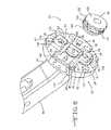
- FIG. 2shows a magnified perspective view of an embodiment of the components that comprise the prosthesis engaging subassembly.
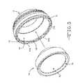
- FIG. 3shows a perspective view of an embodiment of a prosthesis cup implant and a prosthesis cup insert.
- FIG. 4illustrates a perspective view of an embodiment of the impaction plate and the primary and secondary cup contacting members of the prosthesis engaging subassembly.
- FIG. 5shows a magnified perspective view of the components comprising an embodiment of the wedging assembly.
- FIGS. 6-7illustrate perspective views of an embodiment of the prosthesis engaging subassembly being attached to the distal end of the housing.
- FIGS. 8-9illustrate perspective views of an embodiment of the prosthesis engaging subassembly attached to the distal end of the housing along imaginary axes A-A and B-B.
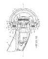
- FIG. 10illustrates a cross-sectional view of an embodiment of a prosthesis cup implant and cup insert ready to be attached to the prosthesis engaging subassembly.
- FIG. 11shows a cross-sectional view of an embodiment of a prosthesis cup being connected to the prosthesis engaging subassembly, the wedging assembly initially moving in a proximal direction.
- FIG. 12illustrates a magnified cross-sectional view of an embodiment of the position of the first and second bands of the first and second conical bodies with respect to the proximal end surfaces of the primary and secondary cup contacting members shown in FIG. 11 .
- FIG. 13shows a cross-sectional view of an embodiment of a prosthesis cup being connected to the prosthesis engaging subassembly, the wedging assembly having been moved in a further proximal direction.
- FIG. 14illustrates a magnified cross-sectional view of an embodiment of the position of the first and second bands of the first and second conical bodies with respect to the proximal end surfaces of the primary and secondary cup contacting members shown in FIG. 13 .
- FIG. 15shows a magnified cross-sectional view of an embodiment of a prosthesis cup connected to the prosthesis engaging subassembly, the wedging assembly having been moved in a furthest proximal direction.
- FIG. 16illustrates a magnified cross-sectional view of an embodiment of the position of the first and second bands of the first and second conical bodies with respect to the proximal end surfaces of the primary and secondary cup contacting members shown in FIG. 15 .
- an acetabular impactor 10is provided to aid the surgeon in controlling installation of an acetabular cup prosthesis 12 ( FIG. 3 ) which may comprise a cup insert 14 positioned therewithin.
- the impactor 10has a housing 16 which encloses a drive train 18 having, at a distal end, a prosthesis cup engaging subassembly 20 , and at the proximal end, a handle 22 which facilitates moving of the drive train 18 by the operator.
- the housing 16may be C-shaped, as shown, in order to minimize invasiveness of the surgery by better clearing anatomical structures and tissue.
- the prosthesis cup engaging subassembly 20as illustrated in FIGS. 1-2 , 4 , 6 - 11 , 13 and 15 , comprises an impaction plate 24 , a primary cup contacting member 26 , a secondary cup contacting member 28 , and a wedging assembly 33 .
- the prosthesis cup engaging subassembly 20may comprise a plurality of primary and secondary cup contacting members 26 , 28 . As shown in FIGS. 1 , 2 , 4 , 69 , two primary cup contacting members 26 and two secondary cup contacting members 28 are illustrated.
- the two primary cup contacting members 26are preferably positioned in an opposing orientation on the surface of the plate 24 .
- first and second primary cup contacting members 26 A, 26 Bare preferably positioned about 90° from respective first and second secondary cup contacting members 28 A, 288 ( FIG. 2 ).
- the primary cup contacting members 26 A, 268are positioned along imaginary axis A-A and the secondary cup contacting members 28 A, 288 are positioned along imaginary axis B-B. Both imaginary axes, A-A and B-B, extend about parallel to the surface of the impaction plate 24 and are about perpendicular to each other.
- the primary cup contacting member 26comprises a lower primary cup contacting member body portion 30 that extends from an upper primary cup contacting member body portion 32 .
- the upper body portion 32is designed to contact an inner surface 34 of the prosthetic cup 12 and/or the cup insert 14 while the lower body portion 30 is designed to provide a means of attachment of the primary member 26 to the impaction plate 24 .
- the upper body portion 32comprises a proximal end portion 36 spaced from a distal end portion 38 by an upper body portion length therebetween.
- the distal end portion 38 of the upper body portion 32 of the primary cup contacting member 26has an outwardly curved surface distal end surface 40 .
- the distal end surface 40is a convex surface that corresponds with an interior concave surface 34 of the prosthetic cup implant 12 or an interior surface 42 of the cup insert 14 .
- the distal end surface 40may have a protruding distal end ridge portion 44 .
- This ridge 44is designed to contact the interior surface 34 , 42 of the respective prosthetic cup 12 or cup insert 14 such that the surface area of the distal end surface 40 , contacting the interior surface 34 , 42 of the prosthetic cup 12 or insert 14 , is minimized.
- a proximal end surface 46having a curved concave surface. As illustrated in FIGS.
- a slot 48having an elongated slot length, extends through the thickness of both the lower body and upper body portions 30 , 32 of the primary cup contacting member 26 .
- the width of the distal end 38 of the upper body portion 32is greater than the width of the proximal end 36 of the upper body portion 32 .
- the lower body portion 30 of the primary cup contacting member 26extends below the upper body portion 32 .
- the lower body portion 30comprises opposing lower body portion sidewalls that form a lower body portion having a length, a width and a depth.
- a lip 50extends perpendicularly from the lower body portion sidewall. This lip 50 , as will be explained in more detail, engages with the impaction plate 24 to provide a secure slidable relation therebetween.
- the secondary cup contacting member 28comprises a distal secondary member end portion 52 spaced from a proximal secondary member end portion 54 .
- the secondary cup contacting member 28further comprises a top sidewall 56 extending to a bottom sidewall 58 and a left sidewall 60 extending to a right sidewall 62 defining a secondary member body 64 .
- a secondary body throughbore 66extends perpendicularly with respect to imaginary axis B-B therethrough. As illustrated in FIGS.
- the secondary cup contacting member 28is positioned on the impaction plate 24 such that a secondary member proximal end surface 68 of the secondary member 28 faces towards the center of the impaction plate 24 and a distal end surface 70 of the secondary member 28 faces towards the outer perimeter of the secondary member 28 .
- the primary cup contacting member 26 and the secondary cup contacting member 28are positioned such that their respective distal end surfaces 40 , 70 form imaginary arcs of differing diameters. More specifically, the distal end surfaces 40 of the primary cup contacting members 26 are positioned about an outer perimeter of the impaction plate 24 .
- the distal end surface 70 of the secondary cup contacting members 28is preferably positioned nearer to the center of the impaction plate 24 , and thus, forms an imaginary arc having a diameter that is smaller than the arc formed by the distal end surfaces 40 of the primary cup contacting members 26 .
- the distal end surfaces 40 , 70 of the respective primary and secondary cup contacting members 26 , 28contact the interior surfaces 34 , 42 of the cup 12 and/or insert 14 at differing depths therewithin. More specifically, as illustrated in FIGS. 11 , 13 , and 15 - 16 , the end surface 40 of the primary cup contacting members 26 is positioned within a cup groove 72 residing just within an outer perimeter 74 of the cup 12 , while a front surface 76 of the distal end 38 of the primary cup contacting members 26 contacts a portion of a proximal end surface 78 of the cup insert 14 .
- the distal end surface 70 of the secondary cup contacting members 28contacts the interior surface 34 of the cup insert 14 distal of the cup groove 72 and deeper within the cup 12 .
- the impactor 10 of the present inventionmay be used without the insert 14 .
- FIGS. 2 , 4 , 6 - 7 , and 11illustrate an embodiment of the impaction plate 24 .
- the plate 24With respect to the plate 24 mounted to the distal end of the impactor 10 housing 16 ( FIG. 1 ), the plate 24 comprises a distal impaction plate surface 80 spaced from a proximal impaction plate surface 82 , an impaction plate thickness 84 therebetween.
- the impaction platefurther comprises an impaction plate opening 86 that extends through the thickness 84 of the plate 24 .
- the opening 86is dimensioned such that a web portion 88 ( FIG. 2 ), extending from a distal end 90 of the housing 16 , is positionable therewithin.
- the opening 86is preferably positioned about the center of the plate 24 such that a central longitudinal axis C-C extends perpendicularly therethrough.
- the impaction plate 24may have a diameter that is about equal to a base diameter of a prosthesis cup 12 .
- a pair of secondary cup contacting alignment rails 92extend outwardly from the distal surface 80 of the impaction plate 24 .
- the rails 92are preferably positioned in a parallel orientation to imaginary axis B-B.
- Each alignment rail 92forms a “guide rail” on which one of the secondary cup contacting members 28 slide in a parallel orientation along axis B-B.
- Corresponding secondary cup contacting member grooves(not shown), positioned within a backside surface of each of the secondary cup contacting members 28 , engage with the rails 92 , thus securing the secondary cup contacting members 28 in a slidable relationship along the distal surface 80 of the impaction plate 24 .
- a pair of secondary cup contacting pins 94extend perpendicularly from the distal surface 80 of the impaction plate 24 .
- the pins 94are preferably positioned through the secondary cup contacting member throughbores 66 that extend through the thickness of the secondary cup contacting members 28 .
- each throughbore 66is an oblong opening that is slightly bigger than the diameter of the elongated body of the pin 94 . This allows the secondary cup contacting pin 94 to secure the secondary member 28 to the plate 24 while providing a limited amount of travel of the member 28 on the distal surface 80 of the plate 24 .
- the opening 66 that extends through the thickness of each of the secondary cup contacting members 28may be designed similar to a slot, thereby providing increased length of travel of the members 28 .
- the impaction plate 24may comprise a primary member channel 96 that resides within the thickness 84 of the impaction plate 24 . More specifically, as illustrated in FIG. 4 , the primary member channel 96 extends longitudinally along imaginary axis A-A, from the outer perimeter of the plate 24 to the central plate opening 86 , within the thickness 84 of the plate 24 .
- the channel 96is designed with an overhang portion 98 that captures the corresponding lip portion 50 of the primary cup contacting members 26 therewithin. As shown in FIG. 4 , the lip portion 50 extends about perpendicular from a backside body portion 100 of each of the primary cup contacting members 26 . When inserted in the channel 96 , the primary cup contact member 26 is in a slideable relationship therewithin.
- a pair of primary posts 102extend upwardly from the distal surface of the channel 96 .
- the long axes of the primary posts 102are positioned about perpendicular to the distal impaction plate surface 80 .
- a pair of primary bias members 104having an elongated length with respective first and second ends, 105 , 107 are preferably positioned adjacent to the primary posts 102 . More specifically, the primary bias members 104 are positioned lengthwise along axis A-A, within the primary member channel 96 , such that their first ends 105 are in a contactable relationship with the primary post 102 .
- the second ends 107 of the primary bias members 104extend towards the outer perimeter of the impaction plate 24 .
- the primary bias members 104 and the primary posts 102are positioned within the slots 48 of the respective primary cup contacting members 26 .
- the primary bias members 104exert an outward force against the primary posts 102 such that the distal end portions 38 of the primary cup contacting members 26 extend outwardly from the central opening of the impaction plate 24 .
- the primary bias members 104exert a force on the primary posts 102 such that the distal end portions 38 of the primary members 26 extend past or out beyond the outer perimeter of the impaction plate 24 .
- the impaction plate 24may comprise a series of impaction plate nodules 106 . These nodules 106 extend outwardly from the distal surface 80 of the impaction plate 24 .
- the nodules 106are designed such that they align with a corresponding cup recess 108 that is positioned about the outer perimeter 74 of the cup 12 as illustrated in FIG. 3 .
- the nodules 106reside within the respective cup recesses 108 ( FIG. 3 ). This interaction between the nodules 106 and cup recesses 108 therefore provides additional stability during the cup impaction process.
- the nodules 106may be constructed having a multitude of non-limiting shapes and forms. As shown in FIGS. 2 and 4 , each of the nodules 106 have a “half-moon” shape, however they may also be of a curved, round, rectangular, triangular, or hexagonal form. In any case, the nodules 106 are designed to fit within the respective cup recess 108 .
- FIGS. 1-2 , 5 - 11 , 13 , 15 and 16An embodiment of the wedging assembly 33 is shown in FIGS. 1-2 , 5 - 11 , 13 , 15 and 16 .
- the wedging assembly 33comprises a wedging assembly proximal end portion 109 ( FIG. 6 ) spaced from a wedging assembly distal end portion 111 that extends longitudinally along imaginary axis C-C ( FIG. 1 ).
- the proximal end portion 109 of the wedging assembly 33is positioned about the opening 86 of the distal surface 80 of the impaction plate 24 .
- the wedging assembly proximal end portion 109may comprise a helical grooved portion 110 therewithin that secures to a threaded portion 112 of the distal end of a drive rod 114 of the drive train 18 , as illustrated in FIGS. 1 , 1 A, 6 and 7 .
- the wedging assembly 33comprises a first body 116 , a second conical body 118 , a cylindrical wave-shaped bias member 120 , an end cap 122 and a locking pin 124 .
- the first body 116has annular sidewall 126 that extends from a ramp surface 138 at its distal end to a first proximal end, a first throughbore 128 extends longitudinally therethrough.
- annular gasket 130circumferentially extends around the proximal end of the first body 116 . As shown, the gasket 130 protrudes outwardly from the outer perimeter of the annular sidewall 126 . As shown, in FIG. 5 , the gasket 130 has a gasket end sidewall 132 that is positioned about perpendicular to the longitudinal axis of the annular sidewall 126 of the first body 116 . The gasket end sidewall 132 encircles the throughbore 128 of the first body 116 . Furthermore, an annular recess 134 is provided radially inwardly of the gasket 130 at the proximal end of the first body 116 . The gasket recess 134 is provided to further engage the web portion 88 ( FIG. 2 ) of the housing 16 .
- a first cone band 136extends circumferentially around the proximal end of the first body 116 .
- the first cone band 136forms an exterior sidewall surrounding the gasket 130 and having a band frustro-conical shape that extends from the proximal end of the body 116 to a point distal of the cone's proximal end.
- the first cone band 136may have an angled or ramped orientation with respect to the annular sidewall 126 of the first body 116 .
- the first band 136may be positioned in an angled relationship ranging from about 5° to about 50° with respect to the exterior surface of the annular sidewall 126 .
- the first cone band 136is positioned such that the diameter, at the proximal end of the first body 116 , is smaller than the diameter located at the distal end of the first body 116 .
- the first cone band 136forms a ramp surface 138 that pushes against the proximal end surface 46 of the primary cup contacting member 26 .
- the ramped surface 138 of the first cone band 136wedges against the proximal end surface 46 of the primary cup contacting member 26 , thereby preventing movement and locking the primary cup contacting member 26 in place against the interior surface of the cup 12 . More specifically, as shown in FIGS.
- a second first cone throughbore 140extends perpendicularly through the annular sidewall 126 of the first conical body 116 at the distal end thereof.
- the second conical body 118resides distal of the first conical body 116 .
- the second conical body 118is of a general cone shape having an annular second conical body sidewall 142 extending from a second conical body distal end 144 to a second conical body proximal end 146 .
- a second conical body throughbore 148extends longitudinally therethrough.
- a second cone end sidewall 150resides at the proximal end of the secondary conical body 118 .
- the end sidewall 150extends circumferentially around the throughbore opening 148 in a perpendicular relationship therewith.
- the second conical body sidewall 142has a frusto-conical shape such that the diameter of the distal end 144 of the secondary conical body 118 is greater than the diameter at the proximal end 146 of the secondary conical body 118 .
- the annular second conical body sidewall 142may be positioned at an angled relationship ranging from about 5° to about 50° with respect to longitudinal axis C-C as shown in FIG. 5 . This angled orientation of the conical body sidewall 142 forms a second cone ramp surface 152 .
- the wedging assembly 33is constructed such that the annular sidewall 126 of the first conical body 116 is positioned through the throughbore 148 of the second conical body 118 .
- a ledge 154 of the gasket portion 130 of the first body 116is positioned on an exterior surface of the end sidewall portion 150 of the second conical body 118 .
- the wedging assembly 33is constructed such that the diameter at the distal end 111 of the assembly 33 is greater than the diameter at the proximal end 109 of the assembly 33 ( FIG. 2 ). Specifically, as shown in FIGS.
- the wedging assembly 33is constructed such that the diameter of the second conical body 118 is greater than the diameter of the first body 116 within the assembly 33 .
- the wedging assembly 33has a ramped surface of increasing diameter from the proximal end portion 109 of the wedging assembly 33 to the distal end portion 111 thereof.
- the annular wave-shaped bias member 120is preferably positioned between the second conical body 118 and the end cap 122 of the wedging assembly 33 .
- the bias member 120provides a bias force against the first and second conical bodies 116 , 118 .
- the end cap 122comprises a cylindrical sidewall 156 that extends from a proximal end to an enlarged gripping portion 158 .
- An end cap throughbore 160resides perpendicularly through the annular sidewall 156 .
- the throughbore 160is dimensioned such that the locking pin 124 may be positioned therethrough.
- the locking pin 124 received in throughbores 140 and 160connects the end cap 122 to the first body 116 with the second conical body 118 and the bias member 120 positioned therebetween.
- a prosthetic cup implant 12is initially positioned at the distal end of the prosthesis engaging subassembly 20 . As shown in FIGS. 11 , 13 , 15 , and 16 , a portion of the distal end 38 of the primary cup contacting body 26 is positioned within the groove 72 ( FIG. 13 ) residing within the proximal end 74 of the prosthesis cup 12 . Specifically, the prosthesis cup 12 is positioned such that the distal end surface 40 of the primary cup contacting body 26 contacts within an interior surface 161 of the groove 72 ( FIG. 15 ) of the cup 12 .
- the primary bias members 104positioned within the slots 48 of the primary cup contacting members 26 , exert a force against the primary posts 102 which biases the distal ends 38 of the members 26 A, 265 to extend forward past the outer perimeter of the impaction plate 24 .
- a prosthesis cup 12is positioned over the distal end portion 38 of the primary cup contacting members 26 A, 26 B. Specifically, a prosthetic cup 12 is positioned over the distal end portion 38 of the primary cup contacting members 26 A, 265 such that a distal end surface 40 or ridge 44 of the members 26 A, 265 resides within the groove 72 of the cup 12 . In addition, a portion of a front surface 76 of the distal end portion 38 of the primary cup contacting members 26 A, 263 contacts a proximal end surface 78 of the prosthetic cup insert 14 .
- the wedging assembly 33is utilized to lock the prosthesis cup 12 in position. Specifically, a downward movement of a lever 164 of the drive train 18 ( FIG. 1 ) towards an exterior surface 166 of the housing 16 at the proximal end of the impactor 10 initiates movement of the drive train and the wedging assembly 33 of the prosthesis engaging subassembly 20 in a proximal direction. Continued downward movement of the lever 164 towards the exterior surface 166 of the housing 16 , thereby pulls the wedging assembly 33 in a further proximal direction within the prosthesis engaging subassembly 20 .
- the exterior surface 138 of the first conical band 136contacts the proximal end surfaces 46 of the primary cup contacting members 26 , thus preventing the distal ends 40 of the primary cup contacting members 26 A, 26 B 26 from moving in an inwardly direction away from the groove 72 of the cup 12 and towards the central opening 86 of the impaction plate 24 .
- movement of the drive train 18forces the primary cup contacting members 26 A, 26 B outwardly into engagement with the prosthesis cup 12 .
- Proximal movement of the second cone sidewall 142causes the distal end surface 70 of the secondary cup contacting members 26 A, 28 B into contact with the interior surface 34 of the cup 12 , particularly an interior surface 42 of the insert 14 positioned within the cup 12 .
- the exterior surface 152 of the second frusto-conical band 142contacts the proximal end surface 68 of the secondary cup contacting members 28 A, 28 B thereby exerting an outward force therebetween.
- the exterior ramp surface 152 of the second band 142 of the second conical body 118wedges against the proximal end surfaces 68 of the secondary cup contacting members 28 A, 28 B causing the distal end surfaces 70 of the secondary members 28 A, 28 B to contact the end surface 78 of the insert 14 . In this manner, movement of the secondary cup contacting members 28 A, 28 B locks the insert 14 in place.
- the wedging assembly 33when the lever 164 is moved in a downward direction towards the exterior surface 166 of the housing 16 , the wedging assembly 33 begins to move in a proximal direction towards the central opening 86 of the impaction plate 24 . Continued proximal movement of the wedging assembly 33 causes the second band 142 of the second cone 118 to first come into contact with the proximal end surfaces 68 of the second cup contacting members 28 A, 28 B. As shown in FIGS.
- the distal end surfaces 70 of the secondary cup contacting members 28 A, 28 Bmove outwardly and contact at least a portion of the interior surface of the cup insert 14 , particularly a portion of the proximal end surface 78 of the insert 14 .
- alignment rails 92positioned within the grove secondary cup contacting member grooves (not shown), ensure the secondary members 28 A, 28 B move about parallel to axis B-B.
- the first conical band 136 of the first body 116contacts the proximal end surfaces 46 of the primary cup contacting members 26 A, 26 B to force them in an outwardly direction. Therefore, the distal end portion 32 of the primary cup contacting members 26 A, 26 B are prevented from retracting towards the central opening 86 of the impaction plate 24 . In addition, the distal surfaces 40 of the primary cup contacting members 26 A, 265 are trapped or locked within the groove 72 of the cup 12 .
- the second cone 118is biased against the bias member 120 such that impaction forces applied to the cup insert 14 by the secondary cone members 28 A, 283 are primarily absorbed by the bias member 120 .
- the magnitude of the forceis primarily absorbed by the bias member 120 .
- some of the impaction forceis absorbed by the first bias members 104 before that force is transferred to the primary cup contacting member 26 .
- the use of the respective distal end surfaces 40 and 70reduces the magnitude of the impaction force transmitted to the cup 12 or insert 14 . This helps prevent damage to the cup 12 and insert 14 during their installation into an acetabulum.
- the prosthesis engaging subassembly 20is connected to the distal end 90 of the housing 16 .
- the cylindrical drive rod 114which is connected to a cylindrical piston 168 , slides through the central axial bore 86 that penetrates through the impaction plate 24 .
- the cylindrical drive rod 114is preferably threaded.
- the cylindrical rod 114is threaded into a corresponding threaded groove of the axial through-bore 128 of the primary body 116 of the wedging assembly 33 securing it in place as shown in FIGS. 6-10 .
- the impaction plate 24may be made of a metallic material such as stainless steel, MP35N, aluminum or the like.
- the primary and secondary cup contacting members 26 A, 26 B, 28 A, 28 Bare preferably made of a polymeric material such as, but not limited to synthetic rubber, neoprene, nylon, poly vinyl chloride (PVC), polystyrene, polyethylene, polypropylene, polyacrylonitrile, polyvinyl butyral (PVB), silicone, polyether ether ketone (PEEK), and the like.
- the piston 168is connected by way of a first U-joint 170 to a lever 172 which slides in a pivoting sleeve 174 fixed to the housing 16 via a pivot 176 .
- the lever 172is connected via a second. U-joint 178 to a second pivoting lever 180 which is fixed to pivot in a catch 182 ( FIG. 1 ) on a pivot pin 184 .
- the catch 182is essentially a divot or a seat cut into the housing 16 , against which the pivot pin 184 of the lever 180 is captured when a slide is slid over the pin 184 when engaged against the seat.
- a slideable sleeve 186slides over the lever 180 and has a trunnion 188 to which a rod 190 is pivotally attached.
- the rod 190passes through a one-way catch 192 in the housing 16 .
- the one-way catch 192can be a captured split wedge sleeve 194 having an inner diameter that just matches the outer diameter of the rod 190 .
- the split wedge sleeve 194is captured in a recess having a matching conical surface that surrounds the sleeve so as to allow the rod 190 to slide into the housing 16 , but to prevent the rod 190 from sliding out of the housing 16 unless an unlock lever (not show) is activated.
- impaction forcesare delivered to the proximal end of the impactor 10 . These impaction forces are intended to drive the prosthetic cup implant 12 to the desired location within the body.
- the tension between distal end surfaces 40 , 70 of the members 26 A, 26 B and 28 A, 28 B against the respective primary and secondary cup contacting members 26 A, 26 B, 28 A and 28 Bare released.
- a release button (not shown) for the one-way catch 192is depressed allowing the rod 190 to move in a reverse direction, thereby relieving the applied pressure of the distal end surfaces 40 , 70 to the prosthetic cup 12 and/or insert 14 .
- the operatormay then pull, back on the handle 22 thereby retracting the impaction plate 24 and wedging assembly 33 of the prosthesis engaging subassembly 20 from the body.
- the inserter 10is removed from the body leaving the double mobility prosthetic cup 12 behind within the body.
- the inserter 10is designed to be disassembled for cleaning by simply sliding the slide back so as to release the pivot 182 and then lifting the drive train 18 out of the housing, but allow it to remain pivotally connected at pivot 176 .
- the piston 168is drawn out of the housing cavity.
- the piston 168is reinserted into the housing cavity and the drive train 18 is rotated back into position, with the one way locking mechanism entering its receiver and the pivot 176 again entering into the catch 182 .
- the slideis then slid over the pivot 176 and the inserter 10 is again ready for use.
- the present inventioncan be packaged in a kit offering a variety of double mobility prosthetic implants 12 of different sizes and diameters.
- the inserter 10 and assorted double mobility implants 12 and subassemblies 20can be packaged in a case with recesses which conveniently hold the components in a convenient, easy to access manner.
Landscapes
- Health & Medical Sciences (AREA)
- Transplantation (AREA)
- Orthopedic Medicine & Surgery (AREA)
- Heart & Thoracic Surgery (AREA)
- Cardiology (AREA)
- Oral & Maxillofacial Surgery (AREA)
- Engineering & Computer Science (AREA)
- Biomedical Technology (AREA)
- Physical Education & Sports Medicine (AREA)
- Vascular Medicine (AREA)
- Life Sciences & Earth Sciences (AREA)
- Animal Behavior & Ethology (AREA)
- General Health & Medical Sciences (AREA)
- Public Health (AREA)
- Veterinary Medicine (AREA)
- Prostheses (AREA)
Abstract
Description
- This application claims priority to U.S. provisional application Ser. No. 61/538,813, filed on Sep. 23, 2011.
- This invention relates to surgical impactors for aiding in installing orthopedic prostheses, and more specifically, to an improved grasping mechanism for installing acetabular implants in the acetabular socket.
- A double mobility prosthetic cup is a type of acetabular implant that is designed to increase a patient's range of hip mobility. Unlike other types of acetabular implants, double mobility prosthetic cups do not have an opening through the cup portion which allows for easy manipulation during implantation. For example, a rod is typically threaded through the cup opening to the apex of the cup dome where there is typically a threaded hole. This rod is used like a handle with which to control and guide the implant during implantation. Double mobility implants, on the other hand, do not have such an opening and therefore create a challenge in controlling them during implantation. The present invention solves this problem and provides an effective novel means of manipulating the double mobility implant during implantation.
- Complicated mechanical devices have crevices and recesses that are difficult, if not almost impossible to clean with ease. Devices that are not properly cleaned and sterilized run the risk of disease transfer from patient to patient following the emergence of certain “prions” that are not killed by normal hospital sterilization and need to be physically removed by washing and rinsing.
- During implantation of the prosthetic cup, a great amount of mechanical force is delivered to the cup implant. Generally, an impacting force is delivered to the proximal end of the impactor which is then imparted to the prosthetic cup at the distal end. The application of such mechanical impacting forces could damage the implant cup, particularly a double mobility prosthetic cup implant since these types of cup implants generally lack the mechanical strength to withstand the application of impaction forces throughout the prosthetic cup. Furthermore, these double mobility prosthetic cups are precisely machined with smooth surfaces. As such, the machined surfaces of these implants could become structurally deformed, cracked or scratched during implantation. In addition, many double mobility prosthetic cups may comprise an insert liner, commonly made of a ceramic material, that is positioned along the interior surface within the cavity of the prosthetic cup. These inserts provide a protective barrier that allows for smooth movement between a metallic joint and the metallic prosthetic cup. Like the prosthesis cup, these inserts could also become structurally deformed, cracked or scratched during implantation. Such damage to the cup and/or cup insert could result in a decrease of mobility for the patient or the need to repeat the prosthetic cup implantation process. Damage could also increase the risk of higher wear rates for the bearing components leading to possible earlier device failure.
- Further, in surgical procedures in which access to the treatment site is limited, it is difficult to use current impactors without subjecting the patient to repeated abrasion and tissue trauma when inserting, operating and extracting surgical instruments.
- Still further, once the appropriate position of the implant is selected, it is often difficult to ensure that the position does not change upon insertion of the assembly through the incision.
- What is needed, therefore, is a double mobility implant impactor that minimizes the potential of damaging the cup implant during implantation. Further, the present invention provides an impactor that is easily adjustable, operatable, disassemblable, and cleanable. Still further, what is needed is an impactor that enables the surgeon to better maneuver, position and install the double mobility implant in a particular angular orientation.
- The present invention relates to an acetabular impactor that aids a surgeon in controlling the installation of a double mobility acetabular prosthesis cup. The impactor has a housing which encloses a drive train having, at a far end, a double mobility prosthetic engaging subassembly, and at the opposite end, a handle which facilitates activation of the drive train and movement of the subassembly. The impactor enables easy orientation of a double mobility prosthesis attached to its end. This is important because precise control of the prosthetic is critical in implantation of the prosthetic in a patient.
- The subassembly comprises a series of components, an impaction plate having a plurality of cup contacting members positioned on an exterior surface of the plate and a wedging assembly attached to a drive rod. The wedging assembly further comprises a first conical body positioned adjacent a second conical body, a conical bias member and an end cap member. The wedging assembly is designed to lock the cup contacting members in direct contact with the prosthesis cup at differing depths within the cup's interior surface, thereby providing a secure fit therebetween. Once positioned within the body, the wedging assembly can be released and the impactor removed, thus leaving the prosthetic cup positioned within the body.
- An objective of the invention is to provide a novel design by which the double mobility cup prosthesis is manipulated and inserted into the body with minimum stresses imparted to the cup. The present invention provides an impactor by which potential damage to the cup during the implantation procedure is minimized.
- A further objective is to provide an impactor that can be “easily cleaned”. Quick and modular disassembly of the impactor enables access to all surfaces that should be cleaned. The reduction in the number of small radius internal corners, crevices and small gaps and the absence of blind holes also aids in sterilization of the instrument.
FIG. 1 is a perspective view of the impactor of the present invention.FIG. 1A is a cross-sectional side view of the impactor shown inFIG. 1 .FIG. 2 shows a magnified perspective view of an embodiment of the components that comprise the prosthesis engaging subassembly.FIG. 3 shows a perspective view of an embodiment of a prosthesis cup implant and a prosthesis cup insert.FIG. 4 illustrates a perspective view of an embodiment of the impaction plate and the primary and secondary cup contacting members of the prosthesis engaging subassembly.FIG. 5 shows a magnified perspective view of the components comprising an embodiment of the wedging assembly.FIGS. 6-7 illustrate perspective views of an embodiment of the prosthesis engaging subassembly being attached to the distal end of the housing.FIGS. 8-9 illustrate perspective views of an embodiment of the prosthesis engaging subassembly attached to the distal end of the housing along imaginary axes A-A and B-B.FIG. 10 illustrates a cross-sectional view of an embodiment of a prosthesis cup implant and cup insert ready to be attached to the prosthesis engaging subassembly.FIG. 11 shows a cross-sectional view of an embodiment of a prosthesis cup being connected to the prosthesis engaging subassembly, the wedging assembly initially moving in a proximal direction.FIG. 12 illustrates a magnified cross-sectional view of an embodiment of the position of the first and second bands of the first and second conical bodies with respect to the proximal end surfaces of the primary and secondary cup contacting members shown inFIG. 11 .FIG. 13 shows a cross-sectional view of an embodiment of a prosthesis cup being connected to the prosthesis engaging subassembly, the wedging assembly having been moved in a further proximal direction.FIG. 14 illustrates a magnified cross-sectional view of an embodiment of the position of the first and second bands of the first and second conical bodies with respect to the proximal end surfaces of the primary and secondary cup contacting members shown inFIG. 13 .FIG. 15 shows a magnified cross-sectional view of an embodiment of a prosthesis cup connected to the prosthesis engaging subassembly, the wedging assembly having been moved in a furthest proximal direction.FIG. 16 illustrates a magnified cross-sectional view of an embodiment of the position of the first and second bands of the first and second conical bodies with respect to the proximal end surfaces of the primary and secondary cup contacting members shown inFIG. 15 .- Referring now to
FIGS. 1-16 , anacetabular impactor 10 is provided to aid the surgeon in controlling installation of an acetabular cup prosthesis12 (FIG. 3 ) which may comprise acup insert 14 positioned therewithin. Theimpactor 10 has ahousing 16 which encloses adrive train 18 having, at a distal end, a prosthesiscup engaging subassembly 20, and at the proximal end, ahandle 22 which facilitates moving of thedrive train 18 by the operator. Thehousing 16 may be C-shaped, as shown, in order to minimize invasiveness of the surgery by better clearing anatomical structures and tissue. - The prosthesis
cup engaging subassembly 20, as illustrated inFIGS. 1-2 ,4,6-11,13 and15, comprises animpaction plate 24, a primarycup contacting member 26, a secondarycup contacting member 28, and awedging assembly 33. In a preferred embodiment, the prosthesiscup engaging subassembly 20 may comprise a plurality of primary and secondarycup contacting members FIGS. 1 ,2,4,69, two primarycup contacting members 26 and two secondarycup contacting members 28 are illustrated. The two primarycup contacting members 26 are preferably positioned in an opposing orientation on the surface of theplate 24. Furthermore, the two secondarycup contacting members 28 are also positioned in an opposing orientation on the surface of theplate 24. As shown, first and second primarycup contacting members cup contacting members 28A,288 (FIG. 2 ). - As shown in
FIG. 4 , the primarycup contacting members 26A,268 are positioned along imaginary axis A-A and the secondarycup contacting members 28A,288 are positioned along imaginary axis B-B. Both imaginary axes, A-A and B-B, extend about parallel to the surface of theimpaction plate 24 and are about perpendicular to each other. - As shown in
FIGS. 2 ,4,6-7, the primarycup contacting member 26 comprises a lower primary cup contactingmember body portion 30 that extends from an upper primary cup contactingmember body portion 32. Theupper body portion 32 is designed to contact aninner surface 34 of theprosthetic cup 12 and/or thecup insert 14 while thelower body portion 30 is designed to provide a means of attachment of theprimary member 26 to theimpaction plate 24. More specifically, theupper body portion 32 comprises aproximal end portion 36 spaced from adistal end portion 38 by an upper body portion length therebetween. In a preferred embodiment, thedistal end portion 38 of theupper body portion 32 of the primarycup contacting member 26 has an outwardly curved surfacedistal end surface 40. In a preferred embodiment, thedistal end surface 40 is a convex surface that corresponds with an interiorconcave surface 34 of theprosthetic cup implant 12 or aninterior surface 42 of thecup insert 14. - As shown in
FIG. 6 , thedistal end surface 40 may have a protruding distalend ridge portion 44. Thisridge 44 is designed to contact theinterior surface prosthetic cup 12 orcup insert 14 such that the surface area of thedistal end surface 40, contacting theinterior surface prosthetic cup 12 orinsert 14, is minimized. At the oppositeproximal end portion 36 of theupper body portion 32 of the primarycup contacting member 26, resides aproximal end surface 46 having a curved concave surface. As illustrated inFIGS. 2 ,4, and6-7, aslot 48, having an elongated slot length, extends through the thickness of both the lower body andupper body portions cup contacting member 26. In a preferred embodiment, the width of thedistal end 38 of theupper body portion 32 is greater than the width of theproximal end 36 of theupper body portion 32. - As previously mentioned, the
lower body portion 30 of the primarycup contacting member 26 extends below theupper body portion 32. Thelower body portion 30 comprises opposing lower body portion sidewalls that form a lower body portion having a length, a width and a depth. In a preferred embodiment, alip 50, as shown inFIG. 4 , extends perpendicularly from the lower body portion sidewall. Thislip 50, as will be explained in more detail, engages with theimpaction plate 24 to provide a secure slidable relation therebetween. - As shown in
FIGS. 2 ,4,6-7 and9, the secondarycup contacting member 28 comprises a distal secondarymember end portion 52 spaced from a proximal secondarymember end portion 54. The secondarycup contacting member 28 further comprises atop sidewall 56 extending to abottom sidewall 58 and aleft sidewall 60 extending to aright sidewall 62 defining asecondary member body 64. A secondary body throughbore66 extends perpendicularly with respect to imaginary axis B-B therethrough. As illustrated inFIGS. 2 ,4,6-7, and9, the secondarycup contacting member 28 is positioned on theimpaction plate 24 such that a secondary memberproximal end surface 68 of thesecondary member 28 faces towards the center of theimpaction plate 24 and adistal end surface 70 of thesecondary member 28 faces towards the outer perimeter of thesecondary member 28. - As shown in
FIGS. 2 , and6-7, the primarycup contacting member 26 and the secondarycup contacting member 28 are positioned such that their respective distal end surfaces40,70 form imaginary arcs of differing diameters. More specifically, the distal end surfaces40 of the primarycup contacting members 26 are positioned about an outer perimeter of theimpaction plate 24. Thedistal end surface 70 of the secondarycup contacting members 28 is preferably positioned nearer to the center of theimpaction plate 24, and thus, forms an imaginary arc having a diameter that is smaller than the arc formed by the distal end surfaces40 of the primarycup contacting members 26. This is designed such that when theprosthetic cup implant 12 is positioned on the end of theprosthesis engaging subassembly 20, the distal end surfaces40,70 of the respective primary and secondarycup contacting members cup 12 and/or insert14 at differing depths therewithin. More specifically, as illustrated inFIGS. 11 ,13, and15-16, theend surface 40 of the primarycup contacting members 26 is positioned within acup groove 72 residing just within anouter perimeter 74 of thecup 12, while afront surface 76 of thedistal end 38 of the primarycup contacting members 26 contacts a portion of aproximal end surface 78 of thecup insert 14. In addition, thedistal end surface 70 of the secondarycup contacting members 28 contacts theinterior surface 34 of thecup insert 14 distal of thecup groove 72 and deeper within thecup 12. Although the use of thecup insert 14 is preferred, theimpactor 10 of the present invention may be used without theinsert 14. FIGS. 2 ,4,6-7, and11, illustrate an embodiment of theimpaction plate 24. With respect to theplate 24 mounted to the distal end of the impactor10 housing16 (FIG. 1 ), theplate 24 comprises a distalimpaction plate surface 80 spaced from a proximalimpaction plate surface 82, animpaction plate thickness 84 therebetween. The impaction plate further comprises an impaction plate opening86 that extends through thethickness 84 of theplate 24. In a preferred embodiment, theopening 86 is dimensioned such that a web portion88 (FIG. 2 ), extending from adistal end 90 of thehousing 16, is positionable therewithin. Theopening 86 is preferably positioned about the center of theplate 24 such that a central longitudinal axis C-C extends perpendicularly therethrough. In a preferred embodiment, theimpaction plate 24 may have a diameter that is about equal to a base diameter of aprosthesis cup 12.- As shown in
FIG. 4 , a pair of secondary cup contactingalignment rails 92 extend outwardly from thedistal surface 80 of theimpaction plate 24. Therails 92 are preferably positioned in a parallel orientation to imaginary axis B-B. Eachalignment rail 92 forms a “guide rail” on which one of the secondarycup contacting members 28 slide in a parallel orientation along axis B-B. Corresponding secondary cup contacting member grooves (not shown), positioned within a backside surface of each of the secondarycup contacting members 28, engage with therails 92, thus securing the secondarycup contacting members 28 in a slidable relationship along thedistal surface 80 of theimpaction plate 24. - Furthermore, as illustrated in
FIG. 4 , a pair of secondarycup contacting pins 94 extend perpendicularly from thedistal surface 80 of theimpaction plate 24. Thepins 94 are preferably positioned through the secondary cup contacting member throughbores66 that extend through the thickness of the secondarycup contacting members 28. In a preferred embodiment, each throughbore66 is an oblong opening that is slightly bigger than the diameter of the elongated body of thepin 94. This allows the secondarycup contacting pin 94 to secure thesecondary member 28 to theplate 24 while providing a limited amount of travel of themember 28 on thedistal surface 80 of theplate 24. In a preferred embodiment, theopening 66 that extends through the thickness of each of the secondarycup contacting members 28 may be designed similar to a slot, thereby providing increased length of travel of themembers 28. - In addition, the
impaction plate 24 may comprise aprimary member channel 96 that resides within thethickness 84 of theimpaction plate 24. More specifically, as illustrated inFIG. 4 , theprimary member channel 96 extends longitudinally along imaginary axis A-A, from the outer perimeter of theplate 24 to thecentral plate opening 86, within thethickness 84 of theplate 24. Thechannel 96 is designed with anoverhang portion 98 that captures thecorresponding lip portion 50 of the primarycup contacting members 26 therewithin. As shown inFIG. 4 , thelip portion 50 extends about perpendicular from abackside body portion 100 of each of the primarycup contacting members 26. When inserted in thechannel 96, the primarycup contact member 26 is in a slideable relationship therewithin. - As shown in
FIG. 4 , a pair ofprimary posts 102 extend upwardly from the distal surface of thechannel 96. The long axes of theprimary posts 102 are positioned about perpendicular to the distalimpaction plate surface 80. A pair ofprimary bias members 104, having an elongated length with respective first and second ends,105,107 are preferably positioned adjacent to theprimary posts 102. More specifically, theprimary bias members 104 are positioned lengthwise along axis A-A, within theprimary member channel 96, such that theirfirst ends 105 are in a contactable relationship with theprimary post 102. The second ends107 of theprimary bias members 104 extend towards the outer perimeter of theimpaction plate 24. In a preferred embodiment, theprimary bias members 104 and theprimary posts 102 are positioned within theslots 48 of the respective primarycup contacting members 26. As shown inFIGS. 10 ,13, and15-16, theprimary bias members 104 exert an outward force against theprimary posts 102 such that thedistal end portions 38 of the primarycup contacting members 26 extend outwardly from the central opening of theimpaction plate 24. More specifically, as shown inFIGS. 10 ,13, and15-16, theprimary bias members 104 exert a force on theprimary posts 102 such that thedistal end portions 38 of theprimary members 26 extend past or out beyond the outer perimeter of theimpaction plate 24. - As shown in
FIG. 4 , theimpaction plate 24 may comprise a series of impaction plate nodules106. Thesenodules 106 extend outwardly from thedistal surface 80 of theimpaction plate 24. Thenodules 106 are designed such that they align with acorresponding cup recess 108 that is positioned about theouter perimeter 74 of thecup 12 as illustrated inFIG. 3 . In a preferred embodiment, when theprosthesis cup 12 is positioned at the end of the prosthesiscup attachment assembly 20, thenodules 106 reside within the respective cup recesses108 (FIG. 3 ). This interaction between thenodules 106 and cup recesses108 therefore provides additional stability during the cup impaction process. Thenodules 106 may be constructed having a multitude of non-limiting shapes and forms. As shown inFIGS. 2 and 4 , each of thenodules 106 have a “half-moon” shape, however they may also be of a curved, round, rectangular, triangular, or hexagonal form. In any case, thenodules 106 are designed to fit within therespective cup recess 108. - An embodiment of the wedging
assembly 33 is shown inFIGS. 1-2 ,5-11,13,15 and16. As shown, the wedgingassembly 33 comprises a wedging assembly proximal end portion109 (FIG. 6 ) spaced from a wedging assemblydistal end portion 111 that extends longitudinally along imaginary axis C-C (FIG. 1 ). In a preferred embodiment, theproximal end portion 109 of the wedgingassembly 33 is positioned about theopening 86 of thedistal surface 80 of theimpaction plate 24. The wedging assemblyproximal end portion 109 may comprise a helicalgrooved portion 110 therewithin that secures to a threadedportion 112 of the distal end of adrive rod 114 of thedrive train 18, as illustrated inFIGS. 1 ,1A,6 and7. - As shown in
FIG. 5 , the wedgingassembly 33 comprises afirst body 116, a secondconical body 118, a cylindrical wave-shapedbias member 120, anend cap 122 and alocking pin 124. Thefirst body 116 hasannular sidewall 126 that extends from aramp surface 138 at its distal end to a first proximal end, afirst throughbore 128 extends longitudinally therethrough. - In a preferred embodiment, an
annular gasket 130 circumferentially extends around the proximal end of thefirst body 116. As shown, thegasket 130 protrudes outwardly from the outer perimeter of theannular sidewall 126. As shown, inFIG. 5 , thegasket 130 has agasket end sidewall 132 that is positioned about perpendicular to the longitudinal axis of theannular sidewall 126 of thefirst body 116. Thegasket end sidewall 132 encircles thethroughbore 128 of thefirst body 116. Furthermore, anannular recess 134 is provided radially inwardly of thegasket 130 at the proximal end of thefirst body 116. Thegasket recess 134 is provided to further engage the web portion88 (FIG. 2 ) of thehousing 16. - A
first cone band 136 extends circumferentially around the proximal end of thefirst body 116. As shown, thefirst cone band 136 forms an exterior sidewall surrounding thegasket 130 and having a band frustro-conical shape that extends from the proximal end of thebody 116 to a point distal of the cone's proximal end. In a preferred embodiment, thefirst cone band 136 may have an angled or ramped orientation with respect to theannular sidewall 126 of thefirst body 116. In an embodiment, thefirst band 136 may be positioned in an angled relationship ranging from about 5° to about 50° with respect to the exterior surface of theannular sidewall 126. As shown inFIG. 5 , thefirst cone band 136 is positioned such that the diameter, at the proximal end of thefirst body 116, is smaller than the diameter located at the distal end of thefirst body 116. - In a preferred embodiment, as illustrated in
FIGS. 13-16 , thefirst cone band 136 forms aramp surface 138 that pushes against theproximal end surface 46 of the primarycup contacting member 26. The rampedsurface 138 of thefirst cone band 136, wedges against theproximal end surface 46 of the primarycup contacting member 26, thereby preventing movement and locking the primarycup contacting member 26 in place against the interior surface of thecup 12. More specifically, as shown inFIGS. 11 ,13,15 and16, the rampedsurface 138 of thefirst cone band 136 wedges against theproximal end surface 46 of the primarycup contacting member 26 which thrusts thedistal end surface 40 of the primarycup contacting member 26 against the interior surfaces34,42 of thecup 12 and/or insert14. In addition, a secondfirst cone throughbore 140 extends perpendicularly through theannular sidewall 126 of the firstconical body 116 at the distal end thereof. - The second
conical body 118 resides distal of the firstconical body 116. The secondconical body 118 is of a general cone shape having an annular secondconical body sidewall 142 extending from a second conical bodydistal end 144 to a second conical bodyproximal end 146. A second conical body throughbore148 extends longitudinally therethrough. A secondcone end sidewall 150 resides at the proximal end of the secondaryconical body 118. In a preferred embodiment, theend sidewall 150 extends circumferentially around thethroughbore opening 148 in a perpendicular relationship therewith. The secondconical body sidewall 142 has a frusto-conical shape such that the diameter of thedistal end 144 of the secondaryconical body 118 is greater than the diameter at theproximal end 146 of the secondaryconical body 118. In an embodiment, the annular secondconical body sidewall 142 may be positioned at an angled relationship ranging from about 5° to about 50° with respect to longitudinal axis C-C as shown inFIG. 5 . This angled orientation of theconical body sidewall 142 forms a secondcone ramp surface 152. - In a preferred embodiment, the wedging
assembly 33 is constructed such that theannular sidewall 126 of the firstconical body 116 is positioned through thethroughbore 148 of the secondconical body 118. In a preferred embodiment, aledge 154 of thegasket portion 130 of thefirst body 116 is positioned on an exterior surface of theend sidewall portion 150 of the secondconical body 118. The wedgingassembly 33 is constructed such that the diameter at thedistal end 111 of theassembly 33 is greater than the diameter at theproximal end 109 of the assembly33 (FIG. 2 ). Specifically, as shown inFIGS. 2 , and5-16, the wedgingassembly 33 is constructed such that the diameter of the secondconical body 118 is greater than the diameter of thefirst body 116 within theassembly 33. Thus, the wedgingassembly 33 has a ramped surface of increasing diameter from theproximal end portion 109 of the wedgingassembly 33 to thedistal end portion 111 thereof. - The annular wave-shaped
bias member 120 is preferably positioned between the secondconical body 118 and theend cap 122 of the wedgingassembly 33. Thebias member 120 provides a bias force against the first and secondconical bodies end cap 122 comprises acylindrical sidewall 156 that extends from a proximal end to an enlargedgripping portion 158. An end cap throughbore160 resides perpendicularly through theannular sidewall 156. Thethroughbore 160 is dimensioned such that thelocking pin 124 may be positioned therethrough. Thelocking pin 124 received inthroughbores end cap 122 to thefirst body 116 with the secondconical body 118 and thebias member 120 positioned therebetween. - In operation, a
prosthetic cup implant 12 is initially positioned at the distal end of theprosthesis engaging subassembly 20. As shown inFIGS. 11 ,13,15, and16, a portion of thedistal end 38 of the primarycup contacting body 26 is positioned within the groove72 (FIG. 13 ) residing within theproximal end 74 of theprosthesis cup 12. Specifically, theprosthesis cup 12 is positioned such that thedistal end surface 40 of the primarycup contacting body 26 contacts within aninterior surface 161 of the groove72 (FIG. 15 ) of thecup 12. Theprimary bias members 104, positioned within theslots 48 of the primarycup contacting members 26, exert a force against theprimary posts 102 which biases the distal ends38 of themembers 26A,265 to extend forward past the outer perimeter of theimpaction plate 24. - A
prosthesis cup 12 is positioned over thedistal end portion 38 of the primarycup contacting members prosthetic cup 12 is positioned over thedistal end portion 38 of the primarycup contacting members 26A,265 such that adistal end surface 40 orridge 44 of themembers 26A,265 resides within thegroove 72 of thecup 12. In addition, a portion of afront surface 76 of thedistal end portion 38 of the primarycup contacting members 26A,263 contacts aproximal end surface 78 of theprosthetic cup insert 14. - Once the
prosthetic cup implant 12 is initially positioned at the distal end of theprosthesis engaging subassembly 20, the wedgingassembly 33 is utilized to lock theprosthesis cup 12 in position. Specifically, a downward movement of alever 164 of the drive train18 (FIG. 1 ) towards anexterior surface 166 of thehousing 16 at the proximal end of the impactor10 initiates movement of the drive train and the wedgingassembly 33 of theprosthesis engaging subassembly 20 in a proximal direction. Continued downward movement of thelever 164 towards theexterior surface 166 of thehousing 16, thereby pulls the wedgingassembly 33 in a further proximal direction within theprosthesis engaging subassembly 20. As the wedgingassembly 33 moves proximally, the combination of the rampingsurfaces conical band 136 and the secondconical body sidewall 142, wedges against the respective proximal end surfaces46,68 of the primary andsecondary members FIGS. 11-14 , as the firstconical band 136 is moved in a proximal direction by thedrive train 18, theexterior surface 138 of the firstconical band 136 contacts the proximal end surfaces46 of the primarycup contacting members 26, thus preventing the distal ends40 of the primarycup contacting members 26 B 26 from moving in an inwardly direction away from thegroove 72 of thecup 12 and towards thecentral opening 86 of theimpaction plate 24. In other words, movement of thedrive train 18 forces the primarycup contacting members prosthesis cup 12. - Proximal movement of the
second cone sidewall 142 causes thedistal end surface 70 of the secondarycup contacting members interior surface 34 of thecup 12, particularly aninterior surface 42 of theinsert 14 positioned within thecup 12. As shown inFIGS. 11-16 , theexterior surface 152 of the second frusto-conical band 142 contacts theproximal end surface 68 of the secondarycup contacting members exterior ramp surface 152 of thesecond band 142 of the secondconical body 118 wedges against the proximal end surfaces68 of the secondarycup contacting members secondary members end surface 78 of theinsert 14. In this manner, movement of the secondarycup contacting members insert 14 in place. - In a preferred embodiment, when the
lever 164 is moved in a downward direction towards theexterior surface 166 of thehousing 16, the wedgingassembly 33 begins to move in a proximal direction towards thecentral opening 86 of theimpaction plate 24. Continued proximal movement of the wedgingassembly 33 causes thesecond band 142 of thesecond cone 118 to first come into contact with the proximal end surfaces68 of the secondcup contacting members FIGS. 11 and 12 , as the wedgingassembly 33 is further moved in a proximal direction, the distal end surfaces70 of the secondarycup contacting members cup insert 14, particularly a portion of theproximal end surface 78 of theinsert 14. As the secondarycup contacting members distal surface 80 of theimpaction plate 24, alignment rails92, positioned within the grove secondary cup contacting member grooves (not shown), ensure thesecondary members - As shown in
FIGS. 13 and 14 , as the wedgingassembly 33 is moved even further in a proximal direction, the firstconical band 136 of thefirst body 116 contacts the proximal end surfaces46 of the primarycup contacting members distal end portion 32 of the primarycup contacting members central opening 86 of theimpaction plate 24. In addition, thedistal surfaces 40 of the primarycup contacting members 26A,265 are trapped or locked within thegroove 72 of thecup 12. It is noted that as the primarycup contacting members distal surface 80 of theimpaction plate 24, theprimary posts 94 which extend through theslot 48 of theprimary members primary members - When the
lever 164 reaches its full downward position and the wedgingassembly 33 is positioned in its full proximal position, as shown inFIGS. 15 and 16 , thedistal surfaces 70 of the secondarycup contacting members cup insert 14, and thedistal surfaces 40 of the primarycup contacting members 26A,265, are in a contactable relationship with the interior surface of thecup groove 72 and theend surface 78 of thecup insert 14. In other words, primarycup contacting members 26A,265 are forced into contact with thecup 12 bysurface 138 and secondarycup contacting members insert 14 bysurface 152. - The
second cone 118 is biased against thebias member 120 such that impaction forces applied to thecup insert 14 by thesecondary cone members 28A,283 are primarily absorbed by thebias member 120. Thus, when an impaction force is applied to the end of thehandle 22, the magnitude of the force is primarily absorbed by thebias member 120. In addition, some of the impaction force is absorbed by thefirst bias members 104 before that force is transferred to the primarycup contacting member 26. Furthermore, the use of the respective distal end surfaces40 and70, with a minimum amount of surface area, reduces the magnitude of the impaction force transmitted to thecup 12 orinsert 14. This helps prevent damage to thecup 12 andinsert 14 during their installation into an acetabulum. - In a preferred embodiment, the
prosthesis engaging subassembly 20 is connected to thedistal end 90 of thehousing 16. Thecylindrical drive rod 114, which is connected to acylindrical piston 168, slides through the central axial bore86 that penetrates through theimpaction plate 24. Thecylindrical drive rod 114 is preferably threaded. Thecylindrical rod 114 is threaded into a corresponding threaded groove of the axial through-bore 128 of theprimary body 116 of the wedgingassembly 33 securing it in place as shown inFIGS. 6-10 . - In a preferred embodiment, the
impaction plate 24 may be made of a metallic material such as stainless steel, MP35N, aluminum or the like. The primary and secondarycup contacting members - With respect to the
drive train 18, thepiston 168 is connected by way of a first U-joint170 to alever 172 which slides in a pivotingsleeve 174 fixed to thehousing 16 via apivot 176. Thelever 172 is connected via a second. U-joint178 to asecond pivoting lever 180 which is fixed to pivot in a catch182 (FIG. 1 ) on apivot pin 184. Thecatch 182 is essentially a divot or a seat cut into thehousing 16, against which thepivot pin 184 of thelever 180 is captured when a slide is slid over thepin 184 when engaged against the seat. - A
slideable sleeve 186 slides over thelever 180 and has atrunnion 188 to which arod 190 is pivotally attached. Therod 190 passes through a one-way catch192 in thehousing 16. The one-way catch192 can be a captured split wedge sleeve194 having an inner diameter that just matches the outer diameter of therod 190. The split wedge sleeve194 is captured in a recess having a matching conical surface that surrounds the sleeve so as to allow therod 190 to slide into thehousing 16, but to prevent therod 190 from sliding out of thehousing 16 unless an unlock lever (not show) is activated. Manipulation of the lever lifts thesleeve 186 out of engagement with the conical surface into an unlocked position to permit therod 190 to back out of thehousing 16. Any number of alternative one-way lock devices may be used, however, the selection of which being within the skill of a person of ordinary skill in this field. For greater detail regarding thedrive train 18 supported by thehousing 16, reference is made to U.S. Pat. No. 7,682,363 to Burgi et al., which is assigned to the assignee of the present invention and incorporated herein by reference. - Once correctly positioned within the body, impaction forces are delivered to the proximal end of the impactor10. These impaction forces are intended to drive the
prosthetic cup implant 12 to the desired location within the body. Once thecup implant 12 is securely in place, the tension between distal end surfaces40,70 of themembers cup contacting members rod 190 to move in a reverse direction, thereby relieving the applied pressure of the distal end surfaces40,70 to theprosthetic cup 12 and/or insert14. The operator may then pull, back on thehandle 22 thereby retracting theimpaction plate 24 and wedgingassembly 33 of theprosthesis engaging subassembly 20 from the body. Theinserter 10 is removed from the body leaving the doublemobility prosthetic cup 12 behind within the body. - The
inserter 10 is designed to be disassembled for cleaning by simply sliding the slide back so as to release thepivot 182 and then lifting thedrive train 18 out of the housing, but allow it to remain pivotally connected atpivot 176. As thedrive train 18 is pivoted, thepiston 168 is drawn out of the housing cavity. To reassemble after cleaning, thepiston 168 is reinserted into the housing cavity and thedrive train 18 is rotated back into position, with the one way locking mechanism entering its receiver and thepivot 176 again entering into thecatch 182. The slide is then slid over thepivot 176 and theinserter 10 is again ready for use. - The present invention can be packaged in a kit offering a variety of double
mobility prosthetic implants 12 of different sizes and diameters. Theinserter 10 and assorteddouble mobility implants 12 andsubassemblies 20 can be packaged in a case with recesses which conveniently hold the components in a convenient, easy to access manner. - The attached drawings represent, by way of example, different embodiments of the subject of the invention. Multiple variations and modifications are possible in the embodiments of the invention described here. Although certain illustrative embodiments of the invention have been shown and described here, a wide range of modifications, changes, and substitutions is contemplated in the foregoing disclosure. In some instances, some features of the present invention may be employed without a corresponding use of the other features. Accordingly, it is appropriate that the foregoing description be construed broadly and understood as being given by way of illustration and example only, the spirit and scope of the invention being limited only by the appended claims.
Claims (38)
Priority Applications (1)
| Application Number | Priority Date | Filing Date | Title |
|---|---|---|---|
| US13/625,023US9028502B2 (en) | 2011-09-23 | 2012-09-24 | Ceramic implant holder |
Applications Claiming Priority (2)
| Application Number | Priority Date | Filing Date | Title |
|---|---|---|---|
| US201161538313P | 2011-09-23 | 2011-09-23 | |
| US13/625,023US9028502B2 (en) | 2011-09-23 | 2012-09-24 | Ceramic implant holder |
Publications (2)
| Publication Number | Publication Date |
|---|---|
| US20130079785A1true US20130079785A1 (en) | 2013-03-28 |
| US9028502B2 US9028502B2 (en) | 2015-05-12 |
Family
ID=46963564
Family Applications (1)
| Application Number | Title | Priority Date | Filing Date |
|---|---|---|---|
| US13/625,023Active2033-08-03US9028502B2 (en) | 2011-09-23 | 2012-09-24 | Ceramic implant holder |
Country Status (2)
| Country | Link |
|---|---|
| US (1) | US9028502B2 (en) |
| EP (1) | EP2572679B1 (en) |
Cited By (13)
| Publication number | Priority date | Publication date | Assignee | Title |
|---|---|---|---|---|
| US20130331849A1 (en)* | 2012-06-07 | 2013-12-12 | Howmedica Osteonics Corp. | Glenosphere inserter and impactor |
| WO2015047627A1 (en)* | 2013-09-30 | 2015-04-02 | DePuy Synthes Products, LLC | Acetabular cup inserter |
| US9028502B2 (en)* | 2011-09-23 | 2015-05-12 | Greatbatch Medical S.A. | Ceramic implant holder |
| US20170027715A1 (en)* | 2015-07-27 | 2017-02-02 | Ren-Hong Huang | Surgical inserter |
| USD780548S1 (en) | 2015-07-22 | 2017-03-07 | Ac (Macao Commercial Offshore) Limited | Power tool |
| USD806493S1 (en) | 2015-07-22 | 2018-01-02 | Tti (Macao Commercial Offshore) Limited | Tool adapter |
| US20180014948A1 (en)* | 2016-07-12 | 2018-01-18 | Dedienne Sante | Assembly for implanting an acetabular cup in a cotyloid cavity |
| US20180049893A1 (en)* | 2015-04-14 | 2018-02-22 | Biomet Manufacturing, Llc | Implant holder |
| US10405991B2 (en) | 2013-09-30 | 2019-09-10 | Depuy Ireland Unlimited Company | Instrument for positioning a cup component of an orthopaedic joint prosthesis |
| US10588756B2 (en) | 2017-03-31 | 2020-03-17 | DePuy Synthes Products, Inc. | System and method for implanting an acetabular prosthetic component |
| US10596011B2 (en) | 2018-01-31 | 2020-03-24 | Depuy Ireland Unlimited Company | Orthopaedic surgical instrument and method for positioning an acetabular prosthetic component |
| US11090163B1 (en)* | 2021-01-09 | 2021-08-17 | Zafer Termanini | Interlocking reverse hip prosthesis with removable tapered central post |
| WO2024020636A1 (en)* | 2022-07-28 | 2024-02-01 | Signature Orthopaedics Europe Ltd | An implant insertion system |
Families Citing this family (6)
| Publication number | Priority date | Publication date | Assignee | Title |
|---|---|---|---|---|
| US20140228854A1 (en)* | 2013-02-08 | 2014-08-14 | Biomet Manufacturing Corporation | Apparatus And Method For Positioning A Prosthesis |
| GB2522045A (en)* | 2014-01-10 | 2015-07-15 | Biomet Uk Healthcare Ltd | Instrument for manipulating an implant |
| EP3111897B1 (en) | 2015-07-02 | 2018-11-14 | Greatbatch Ltd. | Orthopedic impactor |
| CN106983587B (en)* | 2016-01-20 | 2019-03-15 | 北京纳通科技集团有限公司 | Using prosthesis instrument |
| BE1027082B1 (en)* | 2019-02-27 | 2020-09-21 | Zimmer Inc | Tool for clearing a carpal bone |
| US12064356B2 (en) | 2021-08-19 | 2024-08-20 | Howmedica Osteonics Corp. | Multi-size acetabular impactor |
Citations (20)
| Publication number | Priority date | Publication date | Assignee | Title |
|---|---|---|---|---|
| US5059196A (en)* | 1991-03-07 | 1991-10-22 | Dow Corning Wright Corporation | Femoral prosthesis holder/driver tool and method of implantation using same |
| US5171313A (en)* | 1991-05-08 | 1992-12-15 | Othy, Inc. | Tool driver |
| US5540697A (en)* | 1993-02-12 | 1996-07-30 | U.S. Medical Products, Inc. | Prosthetic socket installation apparatus and method |
| US5762391A (en)* | 1993-10-22 | 1998-06-09 | Sez Semiconductor-Equipment Zubehor Fur Die Halbleiterfertigung Gesellschaft M.B.H. | Gripper for disk-shaped articles |
| US5928287A (en)* | 1996-05-09 | 1999-07-27 | Waldemar Link (Gmbh & Co.) | Acetabular cup and surgical instrument for implanting same |
| US5931518A (en)* | 1997-06-18 | 1999-08-03 | Sez Semiconductor- Equipment Zubehor Fur Die Halbleiterfertigung Ag | Gripper for wafer-shaped articles |
| US5954727A (en)* | 1993-10-29 | 1999-09-21 | Howmedica Inc. | Acetabular cup positioning tool and method of positioning an acetabular cup |
| US6827381B1 (en)* | 1996-02-09 | 2004-12-07 | Fritz Schunk Gmbh & Co. Kg Fabrik Fur Spann-Und Greifwerkzeuge | Gripper or clamping device |
| US20060241781A1 (en)* | 2005-04-21 | 2006-10-26 | Biomet Manufacturing Corp. | Method and apparatus for use of porous implants |
| US20070010825A1 (en)* | 2005-06-30 | 2007-01-11 | Leisinger Steven R | Acetabular liner extraction device, kit and associated method |
| US20080077249A1 (en)* | 2004-10-13 | 2008-03-27 | Thomas Gradel | Instruments for Setting Acetabular Cup |
| US20080154261A1 (en)* | 2006-12-21 | 2008-06-26 | Jonas Burgi | Prosthesis Component Holder Attachable to an Inserter Handle |
| US7621921B2 (en)* | 2006-01-25 | 2009-11-24 | Symmetry Medical, Inc | Split thread orthopaedic implant impactor |
| US7727282B2 (en)* | 2006-03-17 | 2010-06-01 | Biomet Manufacturing Corp. | Method and apparatus for implanting a prosthesis |
| US8021370B2 (en)* | 2003-02-03 | 2011-09-20 | Depuy International Ltd. | Instrument for positioning a cup component of an orthopaedic joint prosthesis |
| US20120053592A1 (en)* | 2010-08-27 | 2012-03-01 | Greatbatch Medical S.A. | Offset Cup Impactor With a Grasping Plate for Double Mobility Implants |
| US20120136361A1 (en)* | 2010-11-25 | 2012-05-31 | Benoist Girard Sas | Acetabular cup inserter and impactor |
| US8277457B1 (en)* | 2004-12-09 | 2012-10-02 | Greatbatch Medical S.A. | Orthopaedic inserter using a collet mechanism |
| US8398650B1 (en)* | 2009-01-27 | 2013-03-19 | Greatbatch Medical S.A. | Offset cup impactor with an expandable dome for double mobility implants |
| US8475465B2 (en)* | 2005-01-28 | 2013-07-02 | Steven M. Teeny | Acetabular shell removal tool |
Family Cites Families (108)
| Publication number | Priority date | Publication date | Assignee | Title |
|---|---|---|---|---|
| US1942422A (en) | 1931-06-17 | 1934-01-09 | Daisy B Hanna | Douche device |
| FR2479531A1 (en) | 1980-03-28 | 1981-10-02 | Cgr Ultrasonic | DIGITAL PROCESSING AND MEMORIZATION DEVICE AND SCANNING ECHOGRAPH INCLUDING SUCH A DEVICE |
| USD273806S (en) | 1981-08-03 | 1984-05-08 | Zimmer, Inc. | Reamer/rasp tool, with disposable, debris retaining cutting surface |
| USD272648S (en) | 1981-08-03 | 1984-02-14 | Zimmer, Inc. | Reamer/rasp tool with disposable, debris retaining cutting surface |
| EP0077868A1 (en) | 1981-10-26 | 1983-05-04 | Nunzio Godoli | Hip prosthesis as expanding femoral component |
| US4475549A (en) | 1982-01-18 | 1984-10-09 | Indong Oh | Acetabular cup positioner and method |
| GB8304680D0 (en) | 1983-02-19 | 1983-03-23 | Glynwed Screws & Fastenings Lt | Dispensing apparatus |
| SE459844B (en) | 1983-08-12 | 1989-08-14 | Idea Ab | DEVICE FOR FIXING A LED PROTEST |
| US4528980A (en) | 1983-10-19 | 1985-07-16 | Howmedica, Inc. | Acetabulum sizer and drill guide |
| US4587964A (en) | 1985-02-05 | 1986-05-13 | Zimmer, Inc. | Rasp tool |
| US4632111A (en) | 1985-03-21 | 1986-12-30 | Minnesota Mining And Manufacturing Company | Acetabular cup positioning apparatus |
| US4921493A (en) | 1986-08-11 | 1990-05-01 | Zimmer, Inc. | Rasp tool |
| US4716894A (en) | 1986-08-27 | 1988-01-05 | Zimmer, Inc. | Acetabular cup inserting instrument |
| US4765328A (en) | 1987-08-10 | 1988-08-23 | Osteonics Corp. | Surgical instrument handle coupling |
| US5062854A (en) | 1988-10-07 | 1991-11-05 | Pfizer Hospital Products Group | Prosthetic device and method of implantation |
| US4919679A (en) | 1989-01-31 | 1990-04-24 | Osteonics Corp. | Femoral stem surgical instrument system |
| FR2645433B1 (en) | 1989-04-05 | 1991-06-21 | High Tech Ind | CUP FOR FIXING WITHOUT CEMENT FOR TOTAL HIP PROSTHESIS |
| US5019105A (en) | 1989-08-03 | 1991-05-28 | Biomet, Inc. | Acetabular cup prosthesis assembly |
| US5037424A (en) | 1989-12-21 | 1991-08-06 | Aboczsky Robert I | Instrument for orienting, inserting and impacting an acetabular cup prosthesis |
| US5089003A (en) | 1989-12-22 | 1992-02-18 | Zimmer, Inc. | Rasp tool including detachable handle member |
| US5049158A (en) | 1990-04-20 | 1991-09-17 | Boehringer Mannheim Corporation | Acetabular cup assembly |
| FR2663840B1 (en) | 1990-06-29 | 1998-04-10 | Medinov Sa | PROSTHETIC ASSEMBLY INCLUDING IN PARTICULAR A CUP AND AN IMPACTOR APPARATUS. |
| US5116339A (en) | 1990-07-11 | 1992-05-26 | Glock Steven R | Acetabular cup installation tool and method of installing an acetabular cup |
| US5190549A (en) | 1990-08-02 | 1993-03-02 | Exactech, Inc. | Locking surgical tool handle system |
| US5098437A (en) | 1991-02-13 | 1992-03-24 | Pfizer Hospital Products Group, Inc. | Acetabular cup positioning insert |
| US5133766A (en) | 1991-03-04 | 1992-07-28 | Halpern Alan A | Femoral head remodeling and femoral insert and drilling aid therefor |
| US5061270A (en) | 1991-03-18 | 1991-10-29 | Aboczky Robert I | System for orienting, inserting and impacting an acetabular cup prosthesis |
| US5124106A (en) | 1991-03-25 | 1992-06-23 | Zimmer, Inc. | Method of making a femoral rasp |
| US5342362A (en) | 1991-08-29 | 1994-08-30 | Zimmer Inc. | System and instrumentation for torsionally testing femoral rasp and hip stem implant including motion indicator |
| GB9121132D0 (en) | 1991-10-04 | 1991-11-13 | Johnson & Johnson Orthopaedics | An acetabular cup inserter |
| US5169399A (en) | 1991-10-17 | 1992-12-08 | Boehringer Mannheim Corporation | Acetabular cup impactor |
| US5234432A (en) | 1992-03-13 | 1993-08-10 | Brown Byron L | Method and apparatus for definitive cutting of a femur |
| EP0563585B1 (en) | 1992-04-01 | 1995-08-09 | Imt Integral Medizintechnik Ag | Plastic bone rasp |
| US5261915A (en) | 1992-04-16 | 1993-11-16 | Scott M. Durlacher | Femur bone rasp with adjustable handle |
| US5324293A (en) | 1992-11-13 | 1994-06-28 | U.S. Medical Products, Inc. | Surgical broach and broach holder |
| US5443471A (en) | 1993-02-16 | 1995-08-22 | Howmedica, Inc. | Quick release handle assembly |
| ATE169205T1 (en) | 1993-03-30 | 1998-08-15 | Integral Medizintechnik | PNEUMATIC IMPACT TOOL |
| US5364403A (en) | 1993-09-20 | 1994-11-15 | Zimmer, Inc. | Acetabular cup positioner |
| US6197065B1 (en) | 1993-11-01 | 2001-03-06 | Biomet, Inc. | Method and apparatus for segmental bone replacement |
| US5658294A (en) | 1993-12-02 | 1997-08-19 | Sulzer Orthopedics Inc. | Instrument for holding an acetabular cup |
| US5593451A (en) | 1994-06-01 | 1997-01-14 | Implex Corp. | Prosthetic device and method of implantation |
| DE19521053A1 (en) | 1995-06-09 | 1996-12-12 | Merck Patent Gmbh | Instruments for preparing the medullary canal |
| US5683399A (en) | 1995-12-01 | 1997-11-04 | Stelkast Incorporated | Acetabular cup insertion tool |
| US5665091A (en) | 1996-02-09 | 1997-09-09 | Howmedica Inc. | Surgical broach |
| FR2755603B1 (en) | 1996-11-12 | 1999-02-26 | Jacques Preaut | ASSEMBLY OF ANCILLARS FOR LAYING HIP PROSTHESIS COTYLS, AND READY-TO-FIT COTYL PROSTHETIC ASSEMBLY |
| US5993455A (en) | 1996-11-13 | 1999-11-30 | Noble; Philip C. | Surgical broach and methods for preparing the medullary cavity of a femur in hip arthroplasty |
| US8083745B2 (en) | 2001-05-25 | 2011-12-27 | Conformis, Inc. | Surgical tools for arthroplasty |
| GB2323036B (en) | 1997-03-14 | 2001-04-11 | Finsbury | Prosthetic implant and surgical tool |
| US5913860A (en) | 1998-02-27 | 1999-06-22 | Synthes (Usa) | Surgical nail inserter |
| ES2271978T3 (en) | 1998-06-19 | 2007-04-16 | Imt Integral Medizintechnik Ag | DISPOSABLE BLOOD FOR BONES AND PROCEDURE FOR MANUFACTURING. |
| WO2000012832A2 (en) | 1998-08-26 | 2000-03-09 | Molecular Geodesics, Inc. | Radially expandable device |
| EP1447057A1 (en) | 1998-09-30 | 2004-08-18 | Bard Peripheral Vascular, Inc. | Delivery mechanism for implantable stent |
| US7192449B1 (en) | 1999-01-29 | 2007-03-20 | Orthopaedic Research Institute, Inc. | Constrained acetabular insert for total hip arthroplasty |
| US6063124A (en) | 1999-03-01 | 2000-05-16 | Amstutz; Harlan C. | Acetabular cup prosthesis insertion and removal assembly and technique |
| JP2002537897A (en) | 1999-03-03 | 2002-11-12 | スミス アンド ネフュー インコーポレーテッド | Methods, systems and devices for inserting prosthetic implants |
| WO2000057820A1 (en) | 1999-03-31 | 2000-10-05 | Stocks Gregory W | Joint prosthesis assembly and method for installing same |
| FR2801193B1 (en) | 1999-11-19 | 2002-02-15 | Proconcept | DOUBLE MOBILITY EXPANDABLE COTYLOIDAL PROSTHESIS |
| JP4727891B2 (en) | 2000-02-24 | 2011-07-20 | ストライカー インスツルメンツ | Bioabsorbable joining plate, fastener, tool and method of use thereof |
| US6991656B2 (en) | 2000-04-26 | 2006-01-31 | Dana Mears | Method and apparatus for performing a minimally invasive total hip arthroplasty |
| US6626947B2 (en) | 2000-10-03 | 2003-09-30 | Depuy Orthopaedics, Inc. | Press fit acetabular cup and associated method for securing the cup to an acetabulum |
| US8858564B2 (en) | 2001-02-15 | 2014-10-14 | Spinecore, Inc. | Wedge plate inserter/impactor and related methods for use in implanting an artificial intervertebral disc |
| US6565575B2 (en) | 2001-02-16 | 2003-05-20 | Randall J. Lewis | Method and apparatus for removing an acetabular cup |
| US6723102B2 (en) | 2001-06-14 | 2004-04-20 | Alexandria Research Technologies, Llc | Apparatus and method for minimally invasive total joint replacement |
| US6840959B2 (en) | 2001-07-05 | 2005-01-11 | Howmedica Ostenics Corp. | Pelvic prosthesis plus methods and tools for implantation |
| US6709439B2 (en) | 2001-10-30 | 2004-03-23 | Depuy Spine, Inc. | Slaphammer tool |
| US6716250B2 (en) | 2001-11-05 | 2004-04-06 | Ramin Ganjianpour | Modular femoral prosthesis |
| JP4384498B2 (en) | 2002-02-08 | 2009-12-16 | チャナ,ガーシャラン,シン | Improved surgical device and method of use |
| US6663636B1 (en) | 2002-03-12 | 2003-12-16 | United Orthopedic Corporation | Femur rasp fastener |
| US6916342B2 (en) | 2002-04-01 | 2005-07-12 | Smith & Nephew, Inc. | Liner assembly for prosthetic components |
| US20030229356A1 (en) | 2002-06-10 | 2003-12-11 | Donald Dye | Curved acetabular shell impaction instrument and method of use |
| US7585301B2 (en) | 2002-06-12 | 2009-09-08 | Howmedica Osteonics Corp. | Modular hip inserter/positioner |
| DE10250390A1 (en)* | 2002-10-29 | 2004-05-13 | Plus Endoprothetik Ag | Hip joint cup handling involves spreader cone of axi-slots dividing wall sectors expanded radially onto cup inner wall by central expander for handling all cup types. |
| US7004946B2 (en) | 2002-10-30 | 2006-02-28 | Symmetry Medical, Inc. | Acetabular cup impactor |
| US20050038443A1 (en) | 2002-12-12 | 2005-02-17 | Hedley Anthony K. | Surgical tools for joint replacement |
| FR2850010B1 (en) | 2003-01-17 | 2005-12-02 | Tornier Sa | ANCILLARY FOR THE INSTALLATION OF A PROTHETIC COTYL FOR A HIP PROSTHESIS |
| US7547327B2 (en) | 2003-10-03 | 2009-06-16 | Howmedica Osteonics Corp. | Expandable augment trial |
| EP1691733B1 (en) | 2003-11-10 | 2008-04-23 | Precimed S.A. | Inserter for minimally invasive joint surgery |
| US20050137603A1 (en) | 2003-11-12 | 2005-06-23 | Kevin Belew | Acetabular cup positioning instrument |
| DE602004023422D1 (en) | 2003-11-18 | 2009-11-12 | Smith & Nephew Inc | OPERATIVE TECHNIQUE AND INSTRUMENTS FOR MINIMAL INCISION HIP ARTHOPLASTY SURGERY |
| US7335207B1 (en) | 2003-11-26 | 2008-02-26 | Biomet Manufacturing Corp. | Minimally invasive cup impactor |
| US7833228B1 (en) | 2004-01-05 | 2010-11-16 | Biomet Manufacturing Corp. | Method and instrumentation for performing minimally invasive hip arthroplasty |
| US20050187562A1 (en) | 2004-02-03 | 2005-08-25 | Grimm James E. | Orthopaedic component inserter for use with a surgical navigation system |
| GB0405059D0 (en) | 2004-03-05 | 2004-04-07 | Benoist Girard Sas | Prosthetic acetabular cup inserter |
| DE102004042183A1 (en)* | 2004-06-22 | 2006-01-19 | Plus Endoprothetik Ag | Device for setting or removing joints or joint sockets |
| US7918896B2 (en) | 2004-09-15 | 2011-04-05 | Wright Medical Technology, Inc. | Unitary acetabular cup prosthesis with extension for deficient acetabulum |
| DE602005009402D1 (en) | 2004-12-09 | 2008-10-09 | Precimed Sa | OPERATING INSTRUMENT HOLDER FOR EASIER STERILIZATION |
| US7682363B2 (en) | 2004-12-09 | 2010-03-23 | Greatbatch Medical S.A. | Inserter for minimally invasive joint surgery |
| US7976548B2 (en) | 2005-08-24 | 2011-07-12 | Greatbatch Medical S.A. | Surgical tool holder for facilitated sterilization |
| DE112005003826A5 (en) | 2005-12-15 | 2008-11-20 | Müller, Erich Johann, Dr. med. | Surgical tool and procedure |
| US7993348B2 (en) | 2005-12-20 | 2011-08-09 | Howmedica Osteonics Corp. | Curved acetabular positioner, impactor and reamer handle |
| US20070156155A1 (en) | 2006-01-03 | 2007-07-05 | Parker Brad A | Surgical cup impactor |
| WO2007098549A1 (en) | 2006-03-03 | 2007-09-07 | Portland Orthopaedics Limited | Multi function hammer |
| US20080033444A1 (en) | 2006-03-06 | 2008-02-07 | Howmedica Osteonics Corp. | Compound offset handle |
| US20070225725A1 (en) | 2006-03-21 | 2007-09-27 | Zimmer Technology, Inc. | Modular acetabular component inserter |
| DE102007020484A1 (en) | 2006-05-01 | 2007-12-13 | Precimed S.A. | Insertion instrument for minimally invasive joint surgery with exchangeable thread |
| US20070288096A1 (en) | 2006-06-02 | 2007-12-13 | Gabriel Surma | System and method for inserting an implant |
| US7922726B2 (en) | 2006-06-30 | 2011-04-12 | Greatbatch Medical S.A. | Surgical tool handle and disposable broach assembly |
| GB0617484D0 (en)* | 2006-09-05 | 2006-10-18 | Comis Orthopaedics Ltd | Surgical apparatus |
| US20080255565A1 (en) | 2006-11-20 | 2008-10-16 | Fletcher Henry H | Broach handle for minimally invasive hip replacement surgery |
| US20080146969A1 (en) | 2006-12-15 | 2008-06-19 | Kurtz William B | Total joint replacement component positioning as predetermined distance from center of rotation of the joint using pinless navigation |
| FR2911062B1 (en)* | 2007-01-08 | 2009-07-03 | Thomas Gradel | COTYL WITH STERILE INTERFACE |
| WO2008128282A1 (en) | 2007-04-20 | 2008-10-30 | Portland Orthopaedics Limited | Acetabular prosthesis assembly with offset insert |
| US8858563B2 (en) | 2007-10-30 | 2014-10-14 | Hipco, Inc. | Device and method for hip distention and access |
| US8348953B2 (en) | 2008-01-10 | 2013-01-08 | Peter Brehm | Method and apparatus for impacting bone material |
| US8828008B2 (en) | 2008-03-05 | 2014-09-09 | Allston J. Stubbs | Apparatus for arthroscopic assisted arthroplasty of the hip joint |
| US20090240256A1 (en) | 2008-03-19 | 2009-09-24 | Biomet Manufacturing Corp. | Method And Apparatus For Implanting an Augment |
| GB0808284D0 (en) | 2008-05-07 | 2008-06-11 | Benoist Girard Sas | |
| US9028502B2 (en)* | 2011-09-23 | 2015-05-12 | Greatbatch Medical S.A. | Ceramic implant holder |
- 2012
- 2012-09-24USUS13/625,023patent/US9028502B2/enactiveActive
- 2012-09-24EPEP12185731.2Apatent/EP2572679B1/enactiveActive
Patent Citations (23)
| Publication number | Priority date | Publication date | Assignee | Title |
|---|---|---|---|---|
| US5059196A (en)* | 1991-03-07 | 1991-10-22 | Dow Corning Wright Corporation | Femoral prosthesis holder/driver tool and method of implantation using same |
| US5171313A (en)* | 1991-05-08 | 1992-12-15 | Othy, Inc. | Tool driver |
| US5540697A (en)* | 1993-02-12 | 1996-07-30 | U.S. Medical Products, Inc. | Prosthetic socket installation apparatus and method |
| US5762391A (en)* | 1993-10-22 | 1998-06-09 | Sez Semiconductor-Equipment Zubehor Fur Die Halbleiterfertigung Gesellschaft M.B.H. | Gripper for disk-shaped articles |
| US5954727A (en)* | 1993-10-29 | 1999-09-21 | Howmedica Inc. | Acetabular cup positioning tool and method of positioning an acetabular cup |
| US6827381B1 (en)* | 1996-02-09 | 2004-12-07 | Fritz Schunk Gmbh & Co. Kg Fabrik Fur Spann-Und Greifwerkzeuge | Gripper or clamping device |
| US5928287A (en)* | 1996-05-09 | 1999-07-27 | Waldemar Link (Gmbh & Co.) | Acetabular cup and surgical instrument for implanting same |
| US5931518A (en)* | 1997-06-18 | 1999-08-03 | Sez Semiconductor- Equipment Zubehor Fur Die Halbleiterfertigung Ag | Gripper for wafer-shaped articles |
| US8021370B2 (en)* | 2003-02-03 | 2011-09-20 | Depuy International Ltd. | Instrument for positioning a cup component of an orthopaedic joint prosthesis |
| US20080077249A1 (en)* | 2004-10-13 | 2008-03-27 | Thomas Gradel | Instruments for Setting Acetabular Cup |
| US8277457B1 (en)* | 2004-12-09 | 2012-10-02 | Greatbatch Medical S.A. | Orthopaedic inserter using a collet mechanism |
| US8475465B2 (en)* | 2005-01-28 | 2013-07-02 | Steven M. Teeny | Acetabular shell removal tool |
| US20060241781A1 (en)* | 2005-04-21 | 2006-10-26 | Biomet Manufacturing Corp. | Method and apparatus for use of porous implants |
| US20070010825A1 (en)* | 2005-06-30 | 2007-01-11 | Leisinger Steven R | Acetabular liner extraction device, kit and associated method |
| US7785331B2 (en)* | 2005-06-30 | 2010-08-31 | Depuy Products, Inc. | Acetabular liner extraction device, kit and associated method |
| US7621921B2 (en)* | 2006-01-25 | 2009-11-24 | Symmetry Medical, Inc | Split thread orthopaedic implant impactor |
| US8142439B2 (en)* | 2006-01-25 | 2012-03-27 | Symmetry Medical Manufacturing, Inc. | Method of connecting an impactor to an orthopaedic implant |
| US7727282B2 (en)* | 2006-03-17 | 2010-06-01 | Biomet Manufacturing Corp. | Method and apparatus for implanting a prosthesis |
| US8236003B2 (en)* | 2006-12-21 | 2012-08-07 | Greatbatch Medical S.A. | Prosthesis component holder attachable to an inserter handle |
| US20080154261A1 (en)* | 2006-12-21 | 2008-06-26 | Jonas Burgi | Prosthesis Component Holder Attachable to an Inserter Handle |
| US8398650B1 (en)* | 2009-01-27 | 2013-03-19 | Greatbatch Medical S.A. | Offset cup impactor with an expandable dome for double mobility implants |
| US20120053592A1 (en)* | 2010-08-27 | 2012-03-01 | Greatbatch Medical S.A. | Offset Cup Impactor With a Grasping Plate for Double Mobility Implants |
| US20120136361A1 (en)* | 2010-11-25 | 2012-05-31 | Benoist Girard Sas | Acetabular cup inserter and impactor |
Cited By (17)
| Publication number | Priority date | Publication date | Assignee | Title |
|---|---|---|---|---|
| US9028502B2 (en)* | 2011-09-23 | 2015-05-12 | Greatbatch Medical S.A. | Ceramic implant holder |
| US8900245B2 (en)* | 2012-06-07 | 2014-12-02 | Howmedica Osteonics Corp. | Glenosphere inserter and impactor |
| US20130331849A1 (en)* | 2012-06-07 | 2013-12-12 | Howmedica Osteonics Corp. | Glenosphere inserter and impactor |
| US10405991B2 (en) | 2013-09-30 | 2019-09-10 | Depuy Ireland Unlimited Company | Instrument for positioning a cup component of an orthopaedic joint prosthesis |
| WO2015047627A1 (en)* | 2013-09-30 | 2015-04-02 | DePuy Synthes Products, LLC | Acetabular cup inserter |
| US10842648B2 (en)* | 2015-04-14 | 2020-11-24 | Biomet Manufacturing, Llc | Implant holder |
| US20180049893A1 (en)* | 2015-04-14 | 2018-02-22 | Biomet Manufacturing, Llc | Implant holder |
| USD780548S1 (en) | 2015-07-22 | 2017-03-07 | Ac (Macao Commercial Offshore) Limited | Power tool |
| USD806493S1 (en) | 2015-07-22 | 2018-01-02 | Tti (Macao Commercial Offshore) Limited | Tool adapter |
| US20170027715A1 (en)* | 2015-07-27 | 2017-02-02 | Ren-Hong Huang | Surgical inserter |
| US10470896B2 (en)* | 2015-07-27 | 2019-11-12 | Ren-Hong Huang | Surgical inserter |
| US10245161B2 (en)* | 2016-07-12 | 2019-04-02 | Dedienne Sante | Assembly for implanting an acetabular cup in a cotyloid cavity |
| US20180014948A1 (en)* | 2016-07-12 | 2018-01-18 | Dedienne Sante | Assembly for implanting an acetabular cup in a cotyloid cavity |
| US10588756B2 (en) | 2017-03-31 | 2020-03-17 | DePuy Synthes Products, Inc. | System and method for implanting an acetabular prosthetic component |
| US10596011B2 (en) | 2018-01-31 | 2020-03-24 | Depuy Ireland Unlimited Company | Orthopaedic surgical instrument and method for positioning an acetabular prosthetic component |
| US11090163B1 (en)* | 2021-01-09 | 2021-08-17 | Zafer Termanini | Interlocking reverse hip prosthesis with removable tapered central post |
| WO2024020636A1 (en)* | 2022-07-28 | 2024-02-01 | Signature Orthopaedics Europe Ltd | An implant insertion system |
Also Published As
| Publication number | Publication date |
|---|---|
| EP2572679A1 (en) | 2013-03-27 |
| EP2572679B1 (en) | 2015-07-15 |
| US9028502B2 (en) | 2015-05-12 |
Similar Documents
| Publication | Publication Date | Title |
|---|---|---|
| US9028502B2 (en) | Ceramic implant holder | |
| EP2422754B1 (en) | Offset cup impactor with a grasping plate for double mobility implants | |
| US11464652B2 (en) | Insertion tool assembly | |
| US11696786B2 (en) | Instrument for inserting a spinal device | |
| US7682363B2 (en) | Inserter for minimally invasive joint surgery | |
| US8398650B1 (en) | Offset cup impactor with an expandable dome for double mobility implants | |
| US8277457B1 (en) | Orthopaedic inserter using a collet mechanism | |
| US11766267B2 (en) | Articulating surgical tool | |
| US7850697B2 (en) | Method and apparatus for replacing a spinal disc | |
| US9439778B2 (en) | Device for inserting an intervertebral implant into a body and system including an intervertebral implant and a device for inserting same | |
| US7857816B2 (en) | Inserter for minimally invasive joint surgery having interchangeable thread | |
| USRE43317E1 (en) | Medical installation tool | |
| EP1691733B1 (en) | Inserter for minimally invasive joint surgery | |
| US8585709B2 (en) | Straight cup impactor with lever arm | |
| US9439785B2 (en) | Discretely adjustable hip-replacement trial | |
| US11253373B2 (en) | Limited profile intervertebral implant with incorporated fastening and locking mechanism | |
| KR20140025392A (en) | Novel implant inserter having a laterally-extending dovetail engagement feature | |
| US12150865B2 (en) | Implant packaging cartridge and insertion tool | |
| US12226322B2 (en) | Implant packaging cartridge and insertion tool |
Legal Events
| Date | Code | Title | Description |
|---|---|---|---|
| AS | Assignment | Owner name:GREATBATCH MEDICAL S.A., SWITZERLAND Free format text:ASSIGNMENT OF ASSIGNORS INTEREST;ASSIGNOR:BURGI, JONAS;REEL/FRAME:029010/0398 Effective date:20120828 | |
| STCF | Information on status: patent grant | Free format text:PATENTED CASE | |
| CC | Certificate of correction | ||
| AS | Assignment | Owner name:ROYAL BANK OF CANADA, AS COLLATERAL AGENT, CANADA Free format text:SECURITY INTEREST;ASSIGNOR:BANDERA ACQUISITION, LLC;REEL/FRAME:046472/0475 Effective date:20180702 Owner name:ROYAL BANK OF CANADA, AS COLLATERAL AGENT, CANADA Free format text:SECURITY INTEREST;ASSIGNOR:BANDERA ACQUISITION, LLC;REEL/FRAME:046472/0545 Effective date:20180702 | |
| AS | Assignment | Owner name:BANDERA ACQUISITION, LLC, MASSACHUSETTS Free format text:ASSIGNMENT OF ASSIGNORS INTEREST;ASSIGNOR:GREATBATCH MEDICAL SA;REEL/FRAME:047154/0186 Effective date:20180702 | |
| AS | Assignment | Owner name:VIANT AS&O HOLDINGS, LLC, ARIZONA Free format text:CHANGE OF NAME;ASSIGNOR:BANDERA ACQUISITION, LLC;REEL/FRAME:047221/0275 Effective date:20180824 | |
| MAFP | Maintenance fee payment | Free format text:PAYMENT OF MAINTENANCE FEE, 4TH YEAR, LARGE ENTITY (ORIGINAL EVENT CODE: M1551); ENTITY STATUS OF PATENT OWNER: LARGE ENTITY Year of fee payment:4 | |
| MAFP | Maintenance fee payment | Free format text:PAYMENT OF MAINTENANCE FEE, 8TH YEAR, LARGE ENTITY (ORIGINAL EVENT CODE: M1552); ENTITY STATUS OF PATENT OWNER: LARGE ENTITY Year of fee payment:8 | |
| AS | Assignment | Owner name:VIANT AS&O HOLDINGS, LLC, MASSACHUSETTS Free format text:RELEASE BY SECURED PARTY;ASSIGNOR:ROYAL BANK OF CANADA;REEL/FRAME:069276/0081 Effective date:20241029 | |
| AS | Assignment | Owner name:UBS AG, STAMFORD BRANCH, CONNECTICUT Free format text:SECURITY INTEREST;ASSIGNOR:VIANT AS&O HOLDINGS, LLC;REEL/FRAME:069287/0709 Effective date:20241029 Owner name:VIANT AS&O HOLDINGS, LLC, MASSACHUSETTS Free format text:RELEASE BY SECURED PARTY;ASSIGNOR:ROYAL BANK OF CANADA;REEL/FRAME:069286/0564 Effective date:20241029 | |
| AS | Assignment | Owner name:HPS INVESTMENT PARTNERS, LLC, AS COLLATERAL AGENT, NEW YORK Free format text:SECOND LIEN PATENT SECURITY AGREEMENT;ASSIGNOR:VIANT AS&O HOLDINGS, LLC (F/K/A BANDERA ACQUISITION, LLC);REEL/FRAME:069288/0915 Effective date:20241029 |