US20110040511A1 - Acoustography dynamic range extending device and method - Google Patents
Acoustography dynamic range extending device and methodDownload PDFInfo
- Publication number
- US20110040511A1 US20110040511A1US12/462,902US46290209AUS2011040511A1US 20110040511 A1US20110040511 A1US 20110040511A1US 46290209 AUS46290209 AUS 46290209AUS 2011040511 A1US2011040511 A1US 2011040511A1
- Authority
- US
- United States
- Prior art keywords
- thresholds
- data
- test
- light sensor
- acousto
- Prior art date
- Legal status (The legal status is an assumption and is not a legal conclusion. Google has not performed a legal analysis and makes no representation as to the accuracy of the status listed.)
- Granted
Links
Images

Classifications
- G—PHYSICS
- G01—MEASURING; TESTING
- G01H—MEASUREMENT OF MECHANICAL VIBRATIONS OR ULTRASONIC, SONIC OR INFRASONIC WAVES
- G01H9/00—Measuring mechanical vibrations or ultrasonic, sonic or infrasonic waves by using radiation-sensitive means, e.g. optical means
- G01H9/002—Measuring mechanical vibrations or ultrasonic, sonic or infrasonic waves by using radiation-sensitive means, e.g. optical means for representing acoustic field distribution
Definitions
- the ultra-sound intensity needed to image a highly attenuating region of a test partcauses distortions in imaging of low attenuating regions of the test part. Distortions occur because the ultra-sound intensity needed to image a highly attenuating region is sufficient to cause oscillations in the acousto-optic sensor response for a low attenuating region.
- test part with an extended range of attenuating portionsfor example, because the test part varies in thickness—could not be imaged using a single driving voltage driving the ultra-sound source. And, it was expected that the test part with an extended range of attenuating portions could not be imaged by an increasing driving voltage without waiting for the acousto-optic to reach equilibrium after each increase in voltage.
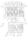
- the acoustography dynamic range extending deviceis represented by 10 .
- the acoustographic systemis represented by 50 , and 20 represents the information system connected 55 with the acoustographic system.
- an ultra-sound sourceis 51 .
- the ultra-sound sourceis driven by a sinusoidal driving voltage. References here to the driving voltage are to peak-to-peak values.
- a medium 52couples the ultra-sound source to an acousto-optic sensor 53 .
- a light sensor 54views the acousto-optic sensor.
- an optional stabilize componentis represented by 21 . This can stabilize the acousto-optic sensor after the mechanical shock caused when the ultra-sound source is activated and before exposure data are captured. This can be done by components of the instructions causing the information system to turn on an electric field across the acousto-optic sensor before activating the ultra-sound source. Alternatively the power to the ultra-sound source can be increased slowly.
- a calibration set of measurements yielding calibration exposure data, with no test object between the ultra-sound source and the acousto-optic sensor, and a test set of measurements yielding test exposure data, with a test object 61 between the ultra-sound source and the acousto-optic sensor,is indicated by 31 and 41 .
- An optional expose componentis represented by 22 with calibration exposure data represented by 32 and the test exposure data represented by 42 .
- a threshold componentis represented by 23 with the recorded calibration thresholds data represented by 33 and the recorded test thresholds data represented by 43 .
- a transformation component for transforming thresholds data to image datais represented by 24 .
- a report component for outputting 27 image datais represented by 26 .
- An optional presentation componentis represented by 25 .
- the presentation componentcan transform image data to presentation forms known in data presentation art.
- the acoustography dynamic range extending devicewhich avoids long-troubling distortions to extend the dynamic range of acoustography comprises an acoustographic system having a light sensor for viewing, and capturing exposures of, an acousto-optic sensor while ultra-sound is incident on the acousto-optic sensor; and comprises dynamic range extending instructions encoded in an information bearing medium readable by an information system.
- the dynamic range extending instructionshave components comprising a threshold component, a transformation component, and a report component.
- the threshold componentis for causing the information system to determine, thresholds to reach a preset brightness for each light sensor pixel in recorded exposure data recorded in the information system.
- Recorded exposure datacomprise calibration exposure data captured by the light sensor while no test part is between the ultra-sound source and the acousto-optic sensor and comprise test exposure data captured by the light sensor while a test part is between the ultra-sound source and the acousto-optic sensor.
- the instructionscan have an optional expose component for causing the information system to cause the acoustographic system to capture the exposure data and to input the exposure data to be recorded in the information system.
- the threshold componentis also for causing the information system to record thresholds as threshold data, where threshold data comprise calibration pixel thresholds—t c —for each light sensor pixel in the calibration data and test pixel thresholds—t p —for each light sensor pixel in the test data.
- Calibration pixel thresholdscan be historical values used with several sets of test exposure data.
- test thresholds (t p )are test times to reach the preset brightness in each imager pixel with a part between the ultrasound source and the acousto-optic sensor
- calibration thresholds (t c )are calibration times to reach the preset brightness in each imager pixel with no part between the ultrasound source and the acousto-optic sensor.
- test thresholds (t p )are test driving voltages needed to reach the preset brightness in each imager pixel with a part between the ultrasound source and the acousto-optic sensor, and
- calibration thresholdsare calibration driving voltages needed to reach the preset brightness in each imager pixel with no part between the ultrasound source and the acousto-optic sensor.
- the preset brightnessis a brightness below the oscillating region of the acousto-optic brightness response for least attenuation. In both cases some highly attenuating portions of the test part man not reach the preset brightness at the highest time in the single voltage case and at the highest voltage in the increasing voltage case.
- the function IC log(t p /t c ), where C is determined by historical data for the specific acoustographic system, can be used. This and other functions must be evaluated for each specific acoustographic system.
- the output componentis for causing the information to cause output of image data.
- the information systemcan be a general purpose device and can be a special purpose device.
- the information systemcan be a component of the acoustographic system, can be stand alone, and can be accessed via a network.
- the acoustography dynamic range extending methodwhich avoids long-troubling distortions to extend the dynamic range of acoustography comprises determining from recorded exposure data thresholds to reach a preset brightness, recording thresholds as threshold data, transforming threshold data to image data, and outputting image data.
- Recorded exposure dataare captured by, and recorded from, an acoustographic system having a light sensor for viewing, and capturing exposures of, an acousto-optic sensor while ultra-sound is incident on the acousto-optic sensor.
- Recorded exposure datacomprise calibration exposure data captured by the light sensor while no test part is between the ultra-sound source and the acousto-optic sensor and comprises test exposure data captured by the light sensor while a test part is between the ultra-sound source and the acousto-optic sensor.
- the step of recording thresholdscomprises recording thresholds as recorded threshold data, where recorded threshold data comprise calibration pixel thresholds—t c —for each light sensor pixel in the calibration data and comprise test pixel thresholds—t p —for each light sensor pixel in the test data.
- test thresholds (t p )are test times to reach the preset brightness in each imager pixel with a part between the ultrasound source and the acousto-optic sensor
- calibration thresholds (t c )are calibration times to reach the preset brightness in each imager pixel with no part between the ultrasound source and the acousto-optic sensor.
- test thresholds (t p )are test driving voltages needed to reach the preset brightness in each imager pixel with a part between the ultrasound source and the acousto-optic sensor, and
- calibration thresholdsare calibration driving voltages needed to reach the preset brightness in each imager pixel with no part between the ultrasound source and the acousto-optic sensor.
- the function IC log(t p /t c ), where C is determined by historical data for the specific acoustographic system, can be used. This and other functions must be evaluated for each specific acoustographic system.
- Steps of the methodcan be caused by dynamic range extending instructions causing the information system to cause the steps.
- the information systemcan be a general purpose device and can be a special purpose device.
- This information systemcan be a component of the acoustographic system, can be stand alone, and can be accessed via a network.
Landscapes
- Engineering & Computer Science (AREA)
- Radar, Positioning & Navigation (AREA)
- Remote Sensing (AREA)
- Physics & Mathematics (AREA)
- General Physics & Mathematics (AREA)
- Investigating Or Analyzing Materials By The Use Of Ultrasonic Waves (AREA)
Abstract
Description
- Unexpected discovery of a transformation which avoids long-troubling distortions to make possible the long-sought goal of extending the dynamic range of acoustography to produce useful images reliably.
- Acoustography is described in U.S. Pat. No. 6,049,411 which is incorporated herein by reference.
- Previously the ultra-sound intensity needed to image a highly attenuating region of a test part causes distortions in imaging of low attenuating regions of the test part. Distortions occur because the ultra-sound intensity needed to image a highly attenuating region is sufficient to cause oscillations in the acousto-optic sensor response for a low attenuating region.
- The long-troubling distortions, the long-sought dynamic range extending goal, and the state of the art for resolving the distortion problem and achieving the goal are described in detail in the publications: Roth, D. J., A. Mandlik, and J. Sandhu, “Approaches for Non-Uniformity Correction and Dynamic Range Extension for Acoustography.”Proceedings of SPIE: Advanced Sensor Technologies for nondestructive Evaluation and Structural Health Monitoring,Bellingham, Wash., SPIE. 2005, pp 124-134 and Roth, D. J., R. A. Martin, L. Hertert, D. T. Chelmins, A. Mandlik, L. A. Cosgriff, and J. Sandhu, “Quantitative Ultrasonic Imaging Using Liquid Crystal Display Technology for Ceramic and Other Composites,”Materials Evaluation,January, 2006, pp 61-65.
- In these publications it was expected that a test part with an extended range of attenuating portions—for example, because the test part varies in thickness—could not be imaged using a single driving voltage driving the ultra-sound source. And, it was expected that the test part with an extended range of attenuating portions could not be imaged by an increasing driving voltage without waiting for the acousto-optic to reach equilibrium after each increase in voltage.
- Both expectations are overcome by discovery that thresholds to reach a preset brightness—using a single driving voltage and alternatively an increasing driving voltage without waiting for the acousto-optic sensor to reach equilibrium after each increase in driving voltage—can be transformed to image data having the long sought extended dynamic range without having the long-troubling distortions.
- In the drawing:
- The acoustography dynamic range extending device is represented by10. The acoustographic system is represented by50, and20 represents the information system connected55 with the acoustographic system.
- In the acoustographic system an ultra-sound source is51. The ultra-sound source is driven by a sinusoidal driving voltage. References here to the driving voltage are to peak-to-peak values. A medium52 couples the ultra-sound source to an acousto-
optic sensor 53. Alight sensor 54 views the acousto-optic sensor. - In the information system an optional stabilize component is represented by21. This can stabilize the acousto-optic sensor after the mechanical shock caused when the ultra-sound source is activated and before exposure data are captured. This can be done by components of the instructions causing the information system to turn on an electric field across the acousto-optic sensor before activating the ultra-sound source. Alternatively the power to the ultra-sound source can be increased slowly.
- That there is a calibration set of measurements yielding calibration exposure data, with no test object between the ultra-sound source and the acousto-optic sensor, and a test set of measurements yielding test exposure data, with a
test object 61 between the ultra-sound source and the acousto-optic sensor, is indicated by31 and41. An optional expose component is represented by22 with calibration exposure data represented by32 and the test exposure data represented by42. - A threshold component is represented by23 with the recorded calibration thresholds data represented by33 and the recorded test thresholds data represented by43.
- A transformation component for transforming thresholds data to image data is represented by24.
- A report component for outputting27 image data is represented by26. An optional presentation component is represented by25. The presentation component can transform image data to presentation forms known in data presentation art.
- The acoustography dynamic range extending device which avoids long-troubling distortions to extend the dynamic range of acoustography comprises an acoustographic system having a light sensor for viewing, and capturing exposures of, an acousto-optic sensor while ultra-sound is incident on the acousto-optic sensor; and comprises dynamic range extending instructions encoded in an information bearing medium readable by an information system.
- Best sensitivity is obtained by viewing the acousto-optic sensor at an optimum angle as described in U.S. Pat. No. 6,049,411.
- The dynamic range extending instructions have components comprising a threshold component, a transformation component, and a report component.
- The threshold component is for causing the information system to determine, thresholds to reach a preset brightness for each light sensor pixel in recorded exposure data recorded in the information system.
- Recorded exposure data comprise calibration exposure data captured by the light sensor while no test part is between the ultra-sound source and the acousto-optic sensor and comprise test exposure data captured by the light sensor while a test part is between the ultra-sound source and the acousto-optic sensor.
- As many as 5,000, and more, exposures can be captured for the calibration exposure data and also for the test calibration data. With 5,000 exposures and with N by M light sensor pixels the calibration exposure data and the test exposure data would each have 5,000 times N times M components.
- The instructions can have an optional expose component for causing the information system to cause the acoustographic system to capture the exposure data and to input the exposure data to be recorded in the information system.
- The threshold component is also for causing the information system to record thresholds as threshold data, where threshold data comprise calibration pixel thresholds—tc—for each light sensor pixel in the calibration data and test pixel thresholds—tp—for each light sensor pixel in the test data.
- Calibration pixel thresholds can be historical values used with several sets of test exposure data.
- When a single driving voltage drives the ultra-sound source, then:
- test thresholds (tp) are test times to reach the preset brightness in each imager pixel with a part between the ultrasound source and the acousto-optic sensor, and
- calibration thresholds (tc) are calibration times to reach the preset brightness in each imager pixel with no part between the ultrasound source and the acousto-optic sensor.
- When an increasing driving voltage drives the ultra-sound source, then:
- test thresholds (tp) are test driving voltages needed to reach the preset brightness in each imager pixel with a part between the ultrasound source and the acousto-optic sensor, and
- calibration thresholds (tc) are calibration driving voltages needed to reach the preset brightness in each imager pixel with no part between the ultrasound source and the acousto-optic sensor.
- In both cases the preset brightness is a brightness below the oscillating region of the acousto-optic brightness response for least attenuation. In both cases some highly attenuating portions of the test part man not reach the preset brightness at the highest time in the single voltage case and at the highest voltage in the increasing voltage case.
- The transformation component is for causing the information system to transform thresholds data to image (I) data for each light sensor pixel using the transformation I=f(tp/tc), where the function f is determined by historical data for the specific acoustographic system.
- The function I=C log(tp/tc), where C is determined by historical data for the specific acoustographic system, can be used. This and other functions must be evaluated for each specific acoustographic system.
- The output component is for causing the information to cause output of image data.
- The information system can be a general purpose device and can be a special purpose device. The information system can be a component of the acoustographic system, can be stand alone, and can be accessed via a network.
- The acoustography dynamic range extending method which avoids long-troubling distortions to extend the dynamic range of acoustography comprises determining from recorded exposure data thresholds to reach a preset brightness, recording thresholds as threshold data, transforming threshold data to image data, and outputting image data.
- Recorded exposure data are captured by, and recorded from, an acoustographic system having a light sensor for viewing, and capturing exposures of, an acousto-optic sensor while ultra-sound is incident on the acousto-optic sensor.
- Recorded exposure data comprise calibration exposure data captured by the light sensor while no test part is between the ultra-sound source and the acousto-optic sensor and comprises test exposure data captured by the light sensor while a test part is between the ultra-sound source and the acousto-optic sensor.
- The step of recording thresholds comprises recording thresholds as recorded threshold data, where recorded threshold data comprise calibration pixel thresholds—tc—for each light sensor pixel in the calibration data and comprise test pixel thresholds—tp—for each light sensor pixel in the test data.
- When a single driving voltage drives the ultra-sound source, then:
- test thresholds (tp) are test times to reach the preset brightness in each imager pixel with a part between the ultrasound source and the acousto-optic sensor, and
- calibration thresholds (tc) are calibration times to reach the preset brightness in each imager pixel with no part between the ultrasound source and the acousto-optic sensor.
- When an increasing driving voltage drives the ultra-sound source, then:
- test thresholds (tp) are test driving voltages needed to reach the preset brightness in each imager pixel with a part between the ultrasound source and the acousto-optic sensor, and
- calibration thresholds (tc) are calibration driving voltages needed to reach the preset brightness in each imager pixel with no part between the ultrasound source and the acousto-optic sensor.
- The step of transforming recorded thresholds data to image data comprises transforming recorded thresholds data to image (I) data for each light sensor pixel using the transformation I=f(tp/tc).
- The function I=C log(tp/tc), where C is determined by historical data for the specific acoustographic system, can be used. This and other functions must be evaluated for each specific acoustographic system.
- Steps of the method can be caused by dynamic range extending instructions causing the information system to cause the steps. The information system can be a general purpose device and can be a special purpose device. This information system can be a component of the acoustographic system, can be stand alone, and can be accessed via a network.
Claims (4)
Priority Applications (1)
| Application Number | Priority Date | Filing Date | Title |
|---|---|---|---|
| US12/462,902US8255180B2 (en) | 2009-08-11 | 2009-08-11 | Acoustography dynamic range extending device and method |
Applications Claiming Priority (1)
| Application Number | Priority Date | Filing Date | Title |
|---|---|---|---|
| US12/462,902US8255180B2 (en) | 2009-08-11 | 2009-08-11 | Acoustography dynamic range extending device and method |
Publications (2)
| Publication Number | Publication Date |
|---|---|
| US20110040511A1true US20110040511A1 (en) | 2011-02-17 |
| US8255180B2 US8255180B2 (en) | 2012-08-28 |
Family
ID=43589086
Family Applications (1)
| Application Number | Title | Priority Date | Filing Date |
|---|---|---|---|
| US12/462,902Expired - Fee RelatedUS8255180B2 (en) | 2009-08-11 | 2009-08-11 | Acoustography dynamic range extending device and method |
Country Status (1)
| Country | Link |
|---|---|
| US (1) | US8255180B2 (en) |
Families Citing this family (1)
| Publication number | Priority date | Publication date | Assignee | Title |
|---|---|---|---|---|
| US10473627B2 (en) | 2017-04-28 | 2019-11-12 | GM Global Technology Operations LLC | Portable acoustic apparatus for in-situ monitoring of a workpiece |
Citations (4)
| Publication number | Priority date | Publication date | Assignee | Title |
|---|---|---|---|---|
| US5447509A (en)* | 1991-01-11 | 1995-09-05 | Baxter International Inc. | Ultrasound catheter system having modulated output with feedback control |
| US6049411A (en)* | 1998-10-14 | 2000-04-11 | Santec Systems Inc | Optical imager for birefringent detector acoustic imaging systems |
| US20060173385A1 (en)* | 2003-06-04 | 2006-08-03 | Lars Lidgren | Ultrasound probe having a central opening |
| US20080054091A1 (en)* | 2005-08-04 | 2008-03-06 | Bacoustics Llc | Ultrasonic atomization and/or seperation system |
- 2009
- 2009-08-11USUS12/462,902patent/US8255180B2/ennot_activeExpired - Fee Related
Patent Citations (4)
| Publication number | Priority date | Publication date | Assignee | Title |
|---|---|---|---|---|
| US5447509A (en)* | 1991-01-11 | 1995-09-05 | Baxter International Inc. | Ultrasound catheter system having modulated output with feedback control |
| US6049411A (en)* | 1998-10-14 | 2000-04-11 | Santec Systems Inc | Optical imager for birefringent detector acoustic imaging systems |
| US20060173385A1 (en)* | 2003-06-04 | 2006-08-03 | Lars Lidgren | Ultrasound probe having a central opening |
| US20080054091A1 (en)* | 2005-08-04 | 2008-03-06 | Bacoustics Llc | Ultrasonic atomization and/or seperation system |
Also Published As
| Publication number | Publication date |
|---|---|
| US8255180B2 (en) | 2012-08-28 |
Similar Documents
| Publication | Publication Date | Title |
|---|---|---|
| EP2685227B1 (en) | Single photon-counting imaging system and method thereof | |
| ATE549855T1 (en) | METHOD FOR PRODUCING AN OPTICAL SYSTEM INCLUDING A PROCESSOR FOR ELECTRONIC IMAGE ENHANCEMENT | |
| AU2003294946A1 (en) | Camera and method for optically recording a screen | |
| US20150036021A1 (en) | Multiple Scattering Medium For Compressive Imaging | |
| ATE500688T1 (en) | METHOD AND APPARATUS FOR REDUCING THE EFFECTS OF DARK CURRENT AND DEFECTIVE PIXELS IN AN IMAGING DEVICE | |
| WO2006029394A3 (en) | Imager flicker compensation systems and methods | |
| WO2015188592A1 (en) | Image calibration method and device | |
| US8255180B2 (en) | Acoustography dynamic range extending device and method | |
| JP2008134426A5 (en) | ||
| US12244952B2 (en) | Single-shot compressed optical-streaking ultra-high-speed photography method and system | |
| CN107837069A (en) | A kind of opto-acoustic microscopic imaging system and method | |
| WO2012004906A1 (en) | Image processing device, image processing method, and program | |
| US20110134280A1 (en) | System and method for constructing high dynamic range images | |
| JP6963240B2 (en) | Cell observation device and program | |
| US6883362B2 (en) | Ultrasonic diagnostic apparatus and method of checking its performance | |
| RU2016115562A (en) | IMAGE CAPTURE DEVICE, IMAGE CAPTURE SYSTEM AND IMAGE CAPTURE METHOD | |
| FR2830629A1 (en) | METHOD AND DEVICE FOR TAKING PART OF A LIGHT BEAM, IN PARTICULAR FOR A FLUORESCENCE ANALYSIS APPARATUS | |
| EP1369250A3 (en) | Method and system for calibrating a spatial light modulator of an imaging engine | |
| KR102243078B1 (en) | Optimal polarization image capture method using a polarization control device and recording medium storing program for executing the same, and computer program stored in recording medium for executing the same | |
| EP2117227A3 (en) | Data transfer device, image stabilisation system and imaging unit | |
| JP2011229111A (en) | Imaging apparatus | |
| JP2010268271A (en) | Imaging device | |
| KR20100099563A (en) | Apparatus and method for reducing dust in digital image processing device | |
| WO2016003655A1 (en) | Compressive sense imaging | |
| US12003868B2 (en) | Imaging system and imaging method thereof |
Legal Events
| Date | Code | Title | Description |
|---|---|---|---|
| ZAAA | Notice of allowance and fees due | Free format text:ORIGINAL CODE: NOA | |
| ZAAB | Notice of allowance mailed | Free format text:ORIGINAL CODE: MN/=. | |
| STCF | Information on status: patent grant | Free format text:PATENTED CASE | |
| FEPP | Fee payment procedure | Free format text:PATENT HOLDER CLAIMS MICRO ENTITY STATUS, ENTITY STATUS SET TO MICRO (ORIGINAL EVENT CODE: STOM); ENTITY STATUS OF PATENT OWNER: MICROENTITY | |
| REMI | Maintenance fee reminder mailed | ||
| FPAY | Fee payment | Year of fee payment:4 | |
| SULP | Surcharge for late payment | ||
| FEPP | Fee payment procedure | Free format text:MAINTENANCE FEE REMINDER MAILED (ORIGINAL EVENT CODE: REM.); ENTITY STATUS OF PATENT OWNER: MICROENTITY | |
| FEPP | Fee payment procedure | Free format text:SURCHARGE FOR LATE PAYMENT, MICRO ENTITY (ORIGINAL EVENT CODE: M3555); ENTITY STATUS OF PATENT OWNER: MICROENTITY | |
| MAFP | Maintenance fee payment | Free format text:PAYMENT OF MAINTENANCE FEE, 8TH YEAR, MICRO ENTITY (ORIGINAL EVENT CODE: M3552); ENTITY STATUS OF PATENT OWNER: MICROENTITY Year of fee payment:8 | |
| FEPP | Fee payment procedure | Free format text:MAINTENANCE FEE REMINDER MAILED (ORIGINAL EVENT CODE: REM.); ENTITY STATUS OF PATENT OWNER: MICROENTITY | |
| LAPS | Lapse for failure to pay maintenance fees | Free format text:PATENT EXPIRED FOR FAILURE TO PAY MAINTENANCE FEES (ORIGINAL EVENT CODE: EXP.); ENTITY STATUS OF PATENT OWNER: MICROENTITY | |
| STCH | Information on status: patent discontinuation | Free format text:PATENT EXPIRED DUE TO NONPAYMENT OF MAINTENANCE FEES UNDER 37 CFR 1.362 | |
| FP | Lapsed due to failure to pay maintenance fee | Effective date:20240828 |