US20100309600A1 - Apparatus for determining and/or monitoring a process variable - Google Patents
Apparatus for determining and/or monitoring a process variableDownload PDFInfo
- Publication number
- US20100309600A1 US20100309600A1US12/735,087US73508708AUS2010309600A1US 20100309600 A1US20100309600 A1US 20100309600A1US 73508708 AUS73508708 AUS 73508708AUS 2010309600 A1US2010309600 A1US 2010309600A1
- Authority
- US
- United States
- Prior art keywords
- voltage
- relay
- increasing unit
- pull
- voltage source
- Prior art date
- Legal status (The legal status is an assumption and is not a legal conclusion. Google has not performed a legal analysis and makes no representation as to the accuracy of the status listed.)
- Granted
Links
- 238000000034methodMethods0.000titleclaimsabstractdescription12
- 238000012544monitoring processMethods0.000titleclaimsabstractdescription7
- 230000003534oscillatory effectEffects0.000claimsdescription25
- 239000003990capacitorSubstances0.000claimsdescription21
- 230000001052transient effectEffects0.000description3
- 238000010586diagramMethods0.000description2
- 230000010355oscillationEffects0.000description2
- 230000000903blocking effectEffects0.000description1
- 238000005516engineering processMethods0.000description1
- 230000002349favourable effectEffects0.000description1
- 238000009499grossingMethods0.000description1
- 239000007788liquidSubstances0.000description1
- 239000012528membraneSubstances0.000description1
Images


Classifications
- G—PHYSICS
- G01—MEASURING; TESTING
- G01F—MEASURING VOLUME, VOLUME FLOW, MASS FLOW OR LIQUID LEVEL; METERING BY VOLUME
- G01F23/00—Indicating or measuring liquid level or level of fluent solid material, e.g. indicating in terms of volume or indicating by means of an alarm
- G01F23/22—Indicating or measuring liquid level or level of fluent solid material, e.g. indicating in terms of volume or indicating by means of an alarm by measuring physical variables, other than linear dimensions, pressure or weight, dependent on the level to be measured, e.g. by difference of heat transfer of steam or water
- G01F23/28—Indicating or measuring liquid level or level of fluent solid material, e.g. indicating in terms of volume or indicating by means of an alarm by measuring physical variables, other than linear dimensions, pressure or weight, dependent on the level to be measured, e.g. by difference of heat transfer of steam or water by measuring the variations of parameters of electromagnetic or acoustic waves applied directly to the liquid or fluent solid material
- G01F23/296—Acoustic waves
- G01F23/2966—Acoustic waves making use of acoustical resonance or standing waves
- G01F23/2967—Acoustic waves making use of acoustical resonance or standing waves for discrete levels
- H—ELECTRICITY
- H01—ELECTRIC ELEMENTS
- H01H—ELECTRIC SWITCHES; RELAYS; SELECTORS; EMERGENCY PROTECTIVE DEVICES
- H01H47/00—Circuit arrangements not adapted to a particular application of the relay and designed to obtain desired operating characteristics or to provide energising current
- H01H47/02—Circuit arrangements not adapted to a particular application of the relay and designed to obtain desired operating characteristics or to provide energising current for modifying the operation of the relay
- H01H47/04—Circuit arrangements not adapted to a particular application of the relay and designed to obtain desired operating characteristics or to provide energising current for modifying the operation of the relay for holding armature in attracted position, e.g. when initial energising circuit is interrupted; for maintaining armature in attracted position, e.g. with reduced energising current
Definitions
- the inventionconcerns an apparatus for determining and/or monitoring at least one process variable.
- the apparatusincludes at least one relay and at least one voltage source.
- the process variableis, for example, fill level, density, viscosity, pressure, flow, pH-value or temperature.
- a so called holding circuitis often used, in the case of which the electrical current is lessened to the holding current.
- the high voltage of 24 Vis kept, however, so that this voltage still negatively affects other circuit parts as regards the power balance. This is particularly the case with linear regulators connected thereafter.
- An object of the inventionis to provide a driver for a relay, in the case of which power loss is reduced.
- An embodimentprovides that the relay and the voltage source are embodied and are matched to one another in such a manner, that at least the voltage, with which the voltage source supplies the relay in the pull-in case, lies below the pull-in voltage of the relay.
- the voltage increasing unitis embodied in such a manner that its produced voltage increase causes the voltage applied to the relay in the moment of the pull-in of the relay to lie above the pull-in voltage, or nominal voltage, of the relay.
- the voltage, with which the voltage source supplies the relay in the holding casei.e. after the pulling in of the relay and therefore in the closed state, is smaller than the pull-in voltage, but at least equal to the holding voltage. Thus, the power loss is lower.
- An embodimentincludes that the relay, the voltage source, and the voltage increasing unit are connected in series.
- An embodimentprovides that the voltage increasing unit has at least one electrical oscillatory circuit.
- An embodimentincludes that the oscillatory circuit involves an LC-oscillatory circuit.
- the voltage increasing unitis embodied as follows:
- An embodimentprovides that the voltage increasing unit has at least one voltage storing unit.
- the voltage storing unitincludes at least one capacitor.
- the inventionreduces the power loss by using a smaller voltage as operating voltage, i.e. for the holding state, and in that the voltage for the relay is increased at the moment of pull-in to the required nominal voltage by the particular voltage increasing unit being used.
- one voltage increasing unitincludes the oscillatory circuit discussed above according to at least one embodiment, and the second voltage increasing unit has available the aforementioned voltage storing unit.
- the transient behavior of the oscillatory circuitis used, and in the other variant the addition of the capacitor voltage is used, in order to produce a voltage increase on the relay.
- FIG. 2a detailed representation of the circuit of the first variant
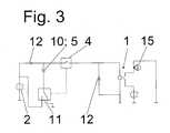
- FIG. 3a second variant for the voltage increase with a dropped-out relay
- FIG. 4the embodiment of FIG. 3 with a pulled-in relay
- FIG. 5a part of a measuring device of the invention with two relays.
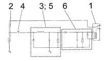
- FIG. 1shows a block diagram of the circuit.
- the voltage source 2is connected via a switch 4 with the relay 1 . If it results, for example, from the measuring of the process variable, that a limit value was exceeded, then the relay 1 is pulled-in by the actuating of switch 4 . If the process variable concerns, for example, the fill level of a medium—e.g. a liquid or a bulk good—in a container, and if the sensor unit involves an oscillatory fork, a single rod, or a membrane oscillator, then, for example, the exceeding of a fill level can be recognized by evaluating the characterizing variables of the oscillations of the sensor unit.
- a mediume.g. a liquid or a bulk good
- the relay 1is pulled-in by a voltage being applied on it, which is equal to or larger than its nominal voltage, or its pull-in voltage.
- the voltage source 2is matched in such a manner to the relay 1 , that the voltage, with which the source 2 supplies the relay 1 , lies below its pull-in voltage.
- the oscillatory circuit 3is provided here as voltage increasing unit 5 , in the case of which involved here is an LC-oscillatory circuit having a coil, a capacitor and a resistor.
- the coil and the capacitorare, in such case, connected in series.
- the resistoris arranged parallel to the capacitor.
- This oscillatory circuit 3is likewise connected with the voltage source 2 and lies in series between the source 2 and the relay 1 . In this way the voltage of the voltage source 2 lies both on the relay 1 , as well as on the voltage increasing unit 5 , i.e. in the ideal case, there is a doubling of the voltage on the relay 1 .
- a rectifier 6is provided, composed of a blocking diode and a smoothing capacitor, which produces a smooth curve from the oscillating signal of the oscillatory circuit 2 .
- the smooth curvefalls corresponding to the attenuation of the amplitude in the oscillatory circuit 3 .
- the transient behavior of an LC-oscillatory circuitis thus made use of.
- the oscillatory circuitis excited and begins to oscillate at the turn-on of the voltage.
- the DC portionis filtered via a capacitance and fed to the relay as pull-in voltage.
- the amplitude and settling timecan be optimized corresponding to the requirements for the switching behavior of the relay.
- the oscillation frequency of the oscillatory circuit 3is matched especially on the inertia of the relay 1 . For the pulling in of the relay 1 , especially only one pulse is used.
- the attenuation and the resonance frequencyare, in such case, to be so chosen, that the relay 1 can switch well and reliably.
- An advantage of this variantlies therein, that essentially only one switch is required for producing the voltage increase, wherein it especially involves the switch that is already required for the switching of the relay.
- FIGS. 3 and 4a second variant of the voltage increasing unit 5 is presented.
- a voltage storing unit 10is here provided, in which it here involves, in particular, a capacitor.
- the capacitor 10is connected here, on the one hand, with the voltage source 2 and, on the other hand, with a reference potential.
- the switch 4 for the relay 1is open in FIG. 3 .
- the voltage source 2 , the capacitor 10 and the relay 1are connected in series.
- an LED 15is provided, which optically displays to the observer, whether the relay is pulled-in.
- FIG. 4shows the switch 4 for the relay 1 closed, i.e. for example, a fill level has been reached by a medium, or another state has occurred, which is to be signaled by the switching of the relay 1 .
- the recharging switch 11Connected with the switch 4 is the recharging switch 11 , which connects the capacitor 10 with the voltage source 2 .
- the voltage source 2 and the capacitor 10are switched in series and correspondingly the sum of both voltages lies on the relay, which pulls in and here, for example, lights the LED 15 .
- the capacitor 10is connected with an additional voltage source, so that in sum also another voltage results for the relay 1 .
- the recharging switch 11is brought back into the position, in which the capacitor 10 is connected with the reference potential, ground, whereby the capacitor 10 can recharge itself.
- the voltage pulse on the relay 1depends on the charging capacitance 10 as well as on the discharge current through the relay 1 . On the whole, a voltage pulse should fall away between about 20 ms and 50 ms. This time is sufficient to switch the relay 1 safely.
- a low operating voltagecan be selected; in the most favorable case, it is half the nominal voltage of the relay 1 . In this second variant two switches are required.
- FIG. 5shows a part of the apparatus of the invention.
- an oscillatory forkis provided here, which serves for determining and monitoring such process variables as, for example, fill level, density or viscosity.
- the voltage source 2is connected here with two relays 21 , 22 . These show, for example, two different switch states or, each the same switch state. The relays can also serve to display an operating state of the measuring device.
- Each relay 21 , 22is connected with its own voltage increasing unit 25 , 26 .
- the first voltage increasing unit 25is executed according to the aforementioned first variant, i.e. an oscillatory circuit serves for the voltage increase, and the second voltage increasing unit 26 has the switched capacitor as voltage storing unit.
Landscapes
- Physics & Mathematics (AREA)
- Acoustics & Sound (AREA)
- Electromagnetism (AREA)
- Thermal Sciences (AREA)
- Fluid Mechanics (AREA)
- General Physics & Mathematics (AREA)
- Engineering & Computer Science (AREA)
- Power Engineering (AREA)
- Dc-Dc Converters (AREA)
- Control Of Voltage And Current In General (AREA)
- Measurement Of Current Or Voltage (AREA)
Abstract
Description
- The invention concerns an apparatus for determining and/or monitoring at least one process variable. The apparatus includes at least one relay and at least one voltage source. The process variable is, for example, fill level, density, viscosity, pressure, flow, pH-value or temperature.
- In measuring devices of process, and automation, technology, relays are sometimes used, in order to signal the presence of switch states or operating states.
- A basic requirement for the development of electronic circuits is always a good power balance, i.e. a power loss that is as low as possible. In the case of operation of a relay, a relatively large amount of power loss can be saved. The relay requires, indeed, a pull-in voltage, which corresponds to the nominal voltage of the relay; however, to hold the relay in the pull-in state, a much smaller voltage, the so called holding voltage, is required. This is clearly shown on the basis of a simple example. Let us say we have a relay with a nominal voltage of 24 V and a resistance of 1600Ω. In order to bring the relay securely into the pulled-in state, the relay is provided with 24 V. From that, an electrical current of 24 V/1600Ω=15 mA results. Associated with that is a power loss of P=15 mA*24 V=360 mW. In order to lessen this power loss, a so called holding circuit is often used, in the case of which the electrical current is lessened to the holding current. The high voltage of 24 V is kept, however, so that this voltage still negatively affects other circuit parts as regards the power balance. This is particularly the case with linear regulators connected thereafter.
- An object of the invention is to provide a driver for a relay, in the case of which power loss is reduced.
- According to the invention, the object is achieved by the features that at least one voltage increasing unit is provided, and that the relay, the voltage source, and the voltage increasing unit are embodied, are matched to one another and are connected with one another in such a manner that, when the voltage source supplies the relay with a voltage for pull-in of the relay, the voltage increasing unit causes such an increase of the voltage applied to the relay, that the applied voltage corresponds at least to the pull-in voltage of the relay. Through the voltage increasing unit, thus, the voltage, with which the relay is supplied in the case of pull-in, is increased in such a manner that it is at least equal to the pull-in voltage, i.e., that a pull-in of the relay, in fact, occurs.
- An embodiment provides that the relay and the voltage source are embodied and are matched to one another in such a manner, that at least the voltage, with which the voltage source supplies the relay in the pull-in case, lies below the pull-in voltage of the relay. Accompanying this embodiment is the feature that the voltage increasing unit is embodied in such a manner that its produced voltage increase causes the voltage applied to the relay in the moment of the pull-in of the relay to lie above the pull-in voltage, or nominal voltage, of the relay. In an additional embodiment of the invention, the voltage, with which the voltage source supplies the relay in the holding case, i.e. after the pulling in of the relay and therefore in the closed state, is smaller than the pull-in voltage, but at least equal to the holding voltage. Thus, the power loss is lower.
- An embodiment includes that the relay, the voltage source, and the voltage increasing unit are connected in series.
- An embodiment provides that the voltage increasing unit is arranged between the voltage source and the relay.
- In at least one of the two preceding embodiments and the arrangements associated with them, the voltage of the voltage source lies, thus, both on the relay, as well as on the voltage increasing unit. Thus, a voltage increase on the relay can be achieved for the moment of pull-in.
- An embodiment provides that the voltage increasing unit has at least one electrical oscillatory circuit.
- An embodiment includes that the oscillatory circuit involves an LC-oscillatory circuit.
- In one variant, an oscillatory circuit is thus used as storage for the electrical voltage, which is transmitted to the relay according to the transient behavior of the oscillatory circuit. In one embodiment, the voltage source is, in such case, connected with the oscillatory circuit and the relay. In an alternative embodiment, the oscillatory circuit is contacted with an additional voltage source.
- In a second variant, the voltage increasing unit is embodied as follows:
- An embodiment provides that the voltage increasing unit has at least one voltage storing unit.
- An embodiment includes that the voltage storing unit is embodied and arranged in such a manner, that in the pull-in case of the relay, the voltage source and the voltage storing unit are connected in series.
- An embodiment provides that the voltage storing unit includes at least one capacitor.
- For all embodiments, it can thus be formulated: The invention reduces the power loss by using a smaller voltage as operating voltage, i.e. for the holding state, and in that the voltage for the relay is increased at the moment of pull-in to the required nominal voltage by the particular voltage increasing unit being used.
- An embodiment provides that at least a first relay and at least a first voltage increasing unit are provided, that at least a second relay and at least a second voltage increasing unit are provided, and that the first voltage increasing unit and the second voltage increasing unit are embodied differently. In this embodiment, the measuring device has available two relays which signal either different states or the same state redundantly. For safety directed applications, it can be required that essential components of a field device be embodied redundantly and diversely. In this embodiment of the apparatus for determining and/or monitoring a process variable, the two relays are connected, each with a differently embodied, thus diverse, voltage increasing unit. The voltage increasing units especially implement, in each case, another method for increasing the voltage. For example, one voltage increasing unit includes the oscillatory circuit discussed above according to at least one embodiment, and the second voltage increasing unit has available the aforementioned voltage storing unit. In the one variant, thus, the transient behavior of the oscillatory circuit is used, and in the other variant the addition of the capacitor voltage is used, in order to produce a voltage increase on the relay.
- The invention will now be explained in greater detail on the basis of the appended drawing, Figures of which show as follows:
FIG. 1 a block diagram of some components of the apparatus of the invention with a first variant of the voltage increasing unit;FIG. 2 a detailed representation of the circuit of the first variant;FIG. 3 a second variant for the voltage increase with a dropped-out relay;FIG. 4 the embodiment ofFIG. 3 with a pulled-in relay; andFIG. 5 a part of a measuring device of the invention with two relays.FIG. 1 shows a block diagram of the circuit. The additional components of the apparatus for determining and/or monitoring a process variable, such as, for example, the actual sensor unit, are not shown.- The
voltage source 2 is connected via aswitch 4 with therelay 1. If it results, for example, from the measuring of the process variable, that a limit value was exceeded, then therelay 1 is pulled-in by the actuating ofswitch 4. If the process variable concerns, for example, the fill level of a medium—e.g. a liquid or a bulk good—in a container, and if the sensor unit involves an oscillatory fork, a single rod, or a membrane oscillator, then, for example, the exceeding of a fill level can be recognized by evaluating the characterizing variables of the oscillations of the sensor unit. - The
relay 1 is pulled-in by a voltage being applied on it, which is equal to or larger than its nominal voltage, or its pull-in voltage. In order to lessen the loss at therelay 1 in the holding state, thevoltage source 2 is matched in such a manner to therelay 1, that the voltage, with which thesource 2 supplies therelay 1, lies below its pull-in voltage. - In order that the
relay 1 does, in fact, pull in at the moment of pull-in, theoscillatory circuit 3 is provided here asvoltage increasing unit 5, in the case of which involved here is an LC-oscillatory circuit having a coil, a capacitor and a resistor. The coil and the capacitor are, in such case, connected in series. The resistor is arranged parallel to the capacitor. Thisoscillatory circuit 3 is likewise connected with thevoltage source 2 and lies in series between thesource 2 and therelay 1. In this way the voltage of thevoltage source 2 lies both on therelay 1, as well as on thevoltage increasing unit 5, i.e. in the ideal case, there is a doubling of the voltage on therelay 1. Behind theoscillatory circuit 3, arectifier 6 is provided, composed of a blocking diode and a smoothing capacitor, which produces a smooth curve from the oscillating signal of theoscillatory circuit 2. The smooth curve falls corresponding to the attenuation of the amplitude in theoscillatory circuit 3. - In this embodiment of
FIG. 1 , the transient behavior of an LC-oscillatory circuit is thus made use of. Through the right choice of the components, the oscillatory circuit is excited and begins to oscillate at the turn-on of the voltage. By the following rectification, the DC portion is filtered via a capacitance and fed to the relay as pull-in voltage. By corresponding dimensioning, the amplitude and settling time can be optimized corresponding to the requirements for the switching behavior of the relay. The oscillation frequency of theoscillatory circuit 3 is matched especially on the inertia of therelay 1. For the pulling in of therelay 1, especially only one pulse is used. - In
FIG. 2 , the individual components of the circuit ofFIG. 1 are presented in detail. Thevoltage source 2 and theoscillatory circuit 3 are connected here with the same reference potential, ground. In the oscillatory circuit, a diode is still arranged between theswitch 4 and the coil and serves as a flyback diode, important for the moment of switch off. Therectifier 6 produces a smoothed signal from the oscillatory signal of the oscillatory circuit via two diodes, a capacitor, and a resistor. The maximum amplitude results, in such case, at the moment when theswitch 4 is closed, i.e. at the instant when therelay 1 should pull-in. Through the attenuation, the voltage then becomes smaller. The attenuation and the resonance frequency are, in such case, to be so chosen, that therelay 1 can switch well and reliably. An advantage of this variant lies therein, that essentially only one switch is required for producing the voltage increase, wherein it especially involves the switch that is already required for the switching of the relay. - In
FIGS. 3 and 4 , a second variant of thevoltage increasing unit 5 is presented. - For the
voltage increasing unit 5, avoltage storing unit 10 is here provided, in which it here involves, in particular, a capacitor. Thecapacitor 10 is connected here, on the one hand, with thevoltage source 2 and, on the other hand, with a reference potential. Theswitch 4 for therelay 1 is open inFIG. 3 . Thevoltage source 2, thecapacitor 10 and therelay 1 are connected in series. Behind therelay 1, anLED 15 is provided, which optically displays to the observer, whether the relay is pulled-in.FIG. 4 shows theswitch 4 for therelay 1 closed, i.e. for example, a fill level has been reached by a medium, or another state has occurred, which is to be signaled by the switching of therelay 1. Connected with theswitch 4 is the rechargingswitch 11, which connects thecapacitor 10 with thevoltage source 2. I.e. thevoltage source 2 and thecapacitor 10 are switched in series and correspondingly the sum of both voltages lies on the relay, which pulls in and here, for example, lights theLED 15. In an alternative embodiment, thecapacitor 10 is connected with an additional voltage source, so that in sum also another voltage results for therelay 1. - This second variant of the voltage increase can also be described as follows: The
capacitor 10 lies via adecoupling diode 12 at the operating voltage of thevoltage source 2 and is charged to this voltage. Therelay 1 is dropped out (FIG. 3 ). By a corresponding sensor signal, the relay operation is, on the one hand, activated. At the same time, the rechargingswitch 11 is switched, so that the low end of thecapacitor 11 lies at the voltage source. In this way, the voltage of thecapacitor 10 and the voltage of thevoltage source 2 add together. If therelay 1 is switched on, thecapacitor 10 is discharged down to the difference between the supply voltage and the voltage falling on thediode 12. This holding voltage is sufficient to hold therelay 1 safely in the pulled in state. If the input signal brings therelay 1 to drop out, then the rechargingswitch 11 is brought back into the position, in which thecapacitor 10 is connected with the reference potential, ground, whereby thecapacitor 10 can recharge itself. The voltage pulse on therelay 1 depends on the chargingcapacitance 10 as well as on the discharge current through therelay 1. On the whole, a voltage pulse should fall away between about 20 ms and 50 ms. This time is sufficient to switch therelay 1 safely. By the circuits ofFIGS. 3 and 4 , a low operating voltage can be selected; in the most favorable case, it is half the nominal voltage of therelay 1. In this second variant two switches are required. FIG. 5 shows a part of the apparatus of the invention. Forsensor unit 30, as an example, an oscillatory fork is provided here, which serves for determining and monitoring such process variables as, for example, fill level, density or viscosity. Thevoltage source 2 is connected here with tworelays - Each
relay voltage increasing unit voltage increasing unit 25 is executed according to the aforementioned first variant, i.e. an oscillatory circuit serves for the voltage increase, and the secondvoltage increasing unit 26 has the switched capacitor as voltage storing unit. - 1 relay
- 2 voltage source
- 3 oscillatory circuit
- 4 switch
- 5 voltage increasing unit
- 6 rectifier
- 10 voltage storing unit
- 11 recharging switch
- 12 diode
- 15 LED
- 21 first relay
- 22 second relay
- 25 first voltage increasing unit
- 26 second voltage increasing unit
- 30 sensor unit
Claims (11)
Applications Claiming Priority (4)
| Application Number | Priority Date | Filing Date | Title |
|---|---|---|---|
| DE102007061180ADE102007061180A1 (en) | 2007-12-15 | 2007-12-15 | Device for determining and / or monitoring a process variable |
| DE102007061180.5 | 2007-12-15 | ||
| DE102007061180 | 2007-12-15 | ||
| PCT/EP2008/067368WO2009077432A1 (en) | 2007-12-15 | 2008-12-12 | Device for determining and/or monitoring a process parameter |
Publications (2)
| Publication Number | Publication Date |
|---|---|
| US20100309600A1true US20100309600A1 (en) | 2010-12-09 |
| US8300380B2 US8300380B2 (en) | 2012-10-30 |
Family
ID=40548807
Family Applications (1)
| Application Number | Title | Priority Date | Filing Date |
|---|---|---|---|
| US12/735,087Expired - Fee RelatedUS8300380B2 (en) | 2007-12-15 | 2008-12-12 | Apparatus for determining and/or monitoring a process variable |
Country Status (5)
| Country | Link |
|---|---|
| US (1) | US8300380B2 (en) |
| EP (1) | EP2217893B1 (en) |
| CN (1) | CN101889191B (en) |
| DE (1) | DE102007061180A1 (en) |
| WO (1) | WO2009077432A1 (en) |
Cited By (2)
| Publication number | Priority date | Publication date | Assignee | Title |
|---|---|---|---|---|
| US20130009464A1 (en)* | 2010-03-23 | 2013-01-10 | A123 Systems, Inc. | System and Method for Controlling a Battery Pack Output Contactor |
| US9103464B2 (en)* | 2009-12-14 | 2015-08-11 | Ushio Denki Kabushiki Kaisha | Holding circuit, electromagnetic valve, valve selector, and flow controller |
Families Citing this family (3)
| Publication number | Priority date | Publication date | Assignee | Title |
|---|---|---|---|---|
| DE102011089996B4 (en)* | 2011-12-27 | 2018-02-01 | Continental Automotive Gmbh | On-board network system and method for operating a vehicle electrical system |
| CN102723238B (en)* | 2012-06-21 | 2015-06-03 | 华为技术有限公司 | Relay drive circuit and control method and system thereof |
| CN110867344A (en)* | 2019-12-26 | 2020-03-06 | 江苏为恒智能科技有限公司 | Novel driving circuit of relay and driving method thereof |
Citations (4)
| Publication number | Priority date | Publication date | Assignee | Title |
|---|---|---|---|---|
| US3585457A (en)* | 1969-05-01 | 1971-06-15 | Fuller Co | Material level sensing device and indicating system |
| US4327693A (en)* | 1980-02-01 | 1982-05-04 | The Bendix Corporation | Solenoid driver using single boost circuit |
| US5317475A (en)* | 1990-08-21 | 1994-05-31 | Siemens Aktiengesellschaft | Circuit arrangement for driving a group of relays |
| US5999396A (en)* | 1995-02-24 | 1999-12-07 | Siemens Aktiengesellschaft | Circuit for driving a contactor |
Family Cites Families (8)
| Publication number | Priority date | Publication date | Assignee | Title |
|---|---|---|---|---|
| AT227841B (en)* | 1960-07-30 | 1963-06-10 | International Standard Electric Corporation | |
| DE3840991A1 (en)* | 1988-12-06 | 1990-06-07 | Eberle Gmbh | Drive circuit for electromagnetic switchgear |
| DE3843339A1 (en)* | 1988-12-22 | 1990-06-28 | Vega Grieshaber Gmbh & Co | Arrangement for capacitive filling level measurement |
| DE9212266U1 (en)* | 1991-10-24 | 1993-03-04 | Siemens AG, 8000 München | Circuit arrangement for controlling a relay |
| DE4325578A1 (en)* | 1993-07-30 | 1995-02-02 | Hartmann & Laemmle Elektronisc | Switching device for an electromagnet |
| DE10125210B4 (en) | 2001-05-21 | 2005-08-18 | Endress + Hauser Gmbh + Co. Kg | Circuit arrangements for feeding a load |
| DE102004058018A1 (en)* | 2004-12-01 | 2006-06-22 | Siemens Ag | Control circuit for a circuit arrangement |
| CN2911946Y (en)* | 2005-12-28 | 2007-06-13 | 广州崎和节能科技发展有限公司 | Energy saving a.c. contactor |
- 2007
- 2007-12-15DEDE102007061180Apatent/DE102007061180A1/ennot_activeWithdrawn
- 2008
- 2008-12-12EPEP08861814.5Apatent/EP2217893B1/enactiveActive
- 2008-12-12WOPCT/EP2008/067368patent/WO2009077432A1/enactiveApplication Filing
- 2008-12-12USUS12/735,087patent/US8300380B2/ennot_activeExpired - Fee Related
- 2008-12-12CNCN2008801197471Apatent/CN101889191B/ennot_activeExpired - Fee Related
Patent Citations (4)
| Publication number | Priority date | Publication date | Assignee | Title |
|---|---|---|---|---|
| US3585457A (en)* | 1969-05-01 | 1971-06-15 | Fuller Co | Material level sensing device and indicating system |
| US4327693A (en)* | 1980-02-01 | 1982-05-04 | The Bendix Corporation | Solenoid driver using single boost circuit |
| US5317475A (en)* | 1990-08-21 | 1994-05-31 | Siemens Aktiengesellschaft | Circuit arrangement for driving a group of relays |
| US5999396A (en)* | 1995-02-24 | 1999-12-07 | Siemens Aktiengesellschaft | Circuit for driving a contactor |
Cited By (2)
| Publication number | Priority date | Publication date | Assignee | Title |
|---|---|---|---|---|
| US9103464B2 (en)* | 2009-12-14 | 2015-08-11 | Ushio Denki Kabushiki Kaisha | Holding circuit, electromagnetic valve, valve selector, and flow controller |
| US20130009464A1 (en)* | 2010-03-23 | 2013-01-10 | A123 Systems, Inc. | System and Method for Controlling a Battery Pack Output Contactor |
Also Published As
| Publication number | Publication date |
|---|---|
| US8300380B2 (en) | 2012-10-30 |
| CN101889191B (en) | 2012-11-28 |
| EP2217893A1 (en) | 2010-08-18 |
| WO2009077432A1 (en) | 2009-06-25 |
| EP2217893B1 (en) | 2021-02-03 |
| DE102007061180A1 (en) | 2009-07-02 |
| CN101889191A (en) | 2010-11-17 |
Similar Documents
| Publication | Publication Date | Title |
|---|---|---|
| US8300380B2 (en) | Apparatus for determining and/or monitoring a process variable | |
| EP0126325B1 (en) | Drive circuit for piezoelectric stack | |
| EP3098866B1 (en) | Piezoelectric power generation module and remote controller | |
| JP6106849B2 (en) | Inertial force sensor | |
| EP2040279A1 (en) | Electronic module for AC/DC coil within an electromagnetic contactor | |
| KR20140074866A (en) | A system and method of remotely connecting and disconnecting the auxiliary power supply of a frequency inverter for varirable capacity compressor employed in cooling systems | |
| US20120232814A1 (en) | Frequency-sampling circuit and method for health prognostics | |
| CN101420180B (en) | Switching power source device | |
| CN108136442B (en) | Piezo actuator driving circuit | |
| WO2001097377A2 (en) | Very high repetition rate power supply system and method | |
| JP2009085487A (en) | Refrigerator control device | |
| EP2960521A1 (en) | Apparatus comprising an oscillation blade fan and method for cleaning the oscillation blade fan | |
| US10916397B2 (en) | Control device for an electromagnetic drive of a switching apparatus | |
| US12072363B2 (en) | Method and generator for characterizing an oscillatory system | |
| CN101256093B (en) | Device for operating a vibrating unit of a vibration resonator | |
| EP3754809B1 (en) | Power management | |
| CN110311577B (en) | DC adapter for driving electromagnetic relay | |
| JP2004260996A (en) | Direct current converter circuit and its driving method | |
| EP3032745A1 (en) | Switching power supply circuit | |
| KR100715773B1 (en) | Power supply for supplying control power | |
| US7057871B2 (en) | Actuation circuit for an electromagnetic actuator | |
| KR102754923B1 (en) | Method for driving engine generation system | |
| KR101070003B1 (en) | Drive control apparatus of pdp using phase-shift | |
| JP2025156851A (en) | Wireless power supply system and inverter control method executed on the power supply side of the wireless power supply system | |
| JP2007180864A (en) | Current control circuit |
Legal Events
| Date | Code | Title | Description |
|---|---|---|---|
| AS | Assignment | Owner name:ENDRESS + HAUSER GMBH + CO. KG, GERMANY Free format text:ASSIGNMENT OF ASSIGNORS INTEREST;ASSIGNORS:BRUTSCHIN, WOLFGANG;RUF, KLAUS;REEL/FRAME:024560/0354 Effective date:20100427 | |
| ZAAA | Notice of allowance and fees due | Free format text:ORIGINAL CODE: NOA | |
| ZAAB | Notice of allowance mailed | Free format text:ORIGINAL CODE: MN/=. | |
| ZAAA | Notice of allowance and fees due | Free format text:ORIGINAL CODE: NOA | |
| STCF | Information on status: patent grant | Free format text:PATENTED CASE | |
| FEPP | Fee payment procedure | Free format text:PAYOR NUMBER ASSIGNED (ORIGINAL EVENT CODE: ASPN); ENTITY STATUS OF PATENT OWNER: LARGE ENTITY | |
| FPAY | Fee payment | Year of fee payment:4 | |
| MAFP | Maintenance fee payment | Free format text:PAYMENT OF MAINTENANCE FEE, 8TH YEAR, LARGE ENTITY (ORIGINAL EVENT CODE: M1552); ENTITY STATUS OF PATENT OWNER: LARGE ENTITY Year of fee payment:8 | |
| FEPP | Fee payment procedure | Free format text:MAINTENANCE FEE REMINDER MAILED (ORIGINAL EVENT CODE: REM.); ENTITY STATUS OF PATENT OWNER: LARGE ENTITY | |
| LAPS | Lapse for failure to pay maintenance fees | Free format text:PATENT EXPIRED FOR FAILURE TO PAY MAINTENANCE FEES (ORIGINAL EVENT CODE: EXP.); ENTITY STATUS OF PATENT OWNER: LARGE ENTITY | |
| STCH | Information on status: patent discontinuation | Free format text:PATENT EXPIRED DUE TO NONPAYMENT OF MAINTENANCE FEES UNDER 37 CFR 1.362 | |
| FP | Lapsed due to failure to pay maintenance fee | Effective date:20241030 |