US20100094489A1 - System and method for reducing a penalty period for a distributed power train - Google Patents
System and method for reducing a penalty period for a distributed power trainDownload PDFInfo
- Publication number
- US20100094489A1 US20100094489A1US12/249,503US24950308AUS2010094489A1US 20100094489 A1US20100094489 A1US 20100094489A1US 24950308 AUS24950308 AUS 24950308AUS 2010094489 A1US2010094489 A1US 2010094489A1
- Authority
- US
- United States
- Prior art keywords
- locomotive
- brake
- remote
- processor
- braking system
- Prior art date
- Legal status (The legal status is an assumption and is not a legal conclusion. Google has not performed a legal analysis and makes no representation as to the accuracy of the status listed.)
- Granted
Links
- 238000000034methodMethods0.000titleclaimsabstractdescription26
- 230000003137locomotive effectEffects0.000claimsabstractdescription144
- 239000012530fluidSubstances0.000claimsabstractdescription19
- 230000001629suppressionEffects0.000claimsdescription16
- 238000013459approachMethods0.000claimsdescription4
- 238000004891communicationMethods0.000claimsdescription4
- 238000012544monitoring processMethods0.000claimsdescription4
- 230000001934delayEffects0.000description3
- 230000004044responseEffects0.000description3
- 230000001960triggered effectEffects0.000description2
- 230000001133accelerationEffects0.000description1
- 238000010586diagramMethods0.000description1
- 230000000694effectsEffects0.000description1
- 230000006870functionEffects0.000description1
- 238000005259measurementMethods0.000description1
- 238000006467substitution reactionMethods0.000description1
- 238000012795verificationMethods0.000description1
Images


Classifications
- B—PERFORMING OPERATIONS; TRANSPORTING
- B61—RAILWAYS
- B61C—LOCOMOTIVES; MOTOR RAILCARS
- B61C17/00—Arrangement or disposition of parts; Details or accessories not otherwise provided for; Use of control gear and control systems
- B61C17/12—Control gear; Arrangements for controlling locomotives from remote points in the train or when operating in multiple units
- B—PERFORMING OPERATIONS; TRANSPORTING
- B60—VEHICLES IN GENERAL
- B60T—VEHICLE BRAKE CONTROL SYSTEMS OR PARTS THEREOF; BRAKE CONTROL SYSTEMS OR PARTS THEREOF, IN GENERAL; ARRANGEMENT OF BRAKING ELEMENTS ON VEHICLES IN GENERAL; PORTABLE DEVICES FOR PREVENTING UNWANTED MOVEMENT OF VEHICLES; VEHICLE MODIFICATIONS TO FACILITATE COOLING OF BRAKES
- B60T13/00—Transmitting braking action from initiating means to ultimate brake actuator with power assistance or drive; Brake systems incorporating such transmitting means, e.g. air-pressure brake systems
- B60T13/10—Transmitting braking action from initiating means to ultimate brake actuator with power assistance or drive; Brake systems incorporating such transmitting means, e.g. air-pressure brake systems with fluid assistance, drive, or release
- B60T13/66—Electrical control in fluid-pressure brake systems
- B60T13/665—Electrical control in fluid-pressure brake systems the systems being specially adapted for transferring two or more command signals, e.g. railway systems
- B—PERFORMING OPERATIONS; TRANSPORTING
- B60—VEHICLES IN GENERAL
- B60T—VEHICLE BRAKE CONTROL SYSTEMS OR PARTS THEREOF; BRAKE CONTROL SYSTEMS OR PARTS THEREOF, IN GENERAL; ARRANGEMENT OF BRAKING ELEMENTS ON VEHICLES IN GENERAL; PORTABLE DEVICES FOR PREVENTING UNWANTED MOVEMENT OF VEHICLES; VEHICLE MODIFICATIONS TO FACILITATE COOLING OF BRAKES
- B60T17/00—Component parts, details, or accessories of power brake systems not covered by groups B60T8/00, B60T13/00 or B60T15/00, or presenting other characteristic features
- B60T17/18—Safety devices; Monitoring
- B60T17/22—Devices for monitoring or checking brake systems; Signal devices
- B60T17/228—Devices for monitoring or checking brake systems; Signal devices for railway vehicles
Definitions
- Distributed power train operationinvolves the controlled coordination of motive power supplied from a lead locomotive and one or more remote locomotives spaced apart from the lead locomotive in a train consist.
- the lead and remote locomotivesare linked together and controlled in concert to pull or otherwise move one or more non-powered load vehicles.
- Each lead and remote locomotiveincludes a braking processor for controlling the operations of a respective braking system and a communication system for exchanging information between the lead and remote locomotives over a communication link.
- a brake pipefluidically interconnects each of the locomotives and rail cars of the train wherein modulation of a fluid flow, such as a fluid pressure in the brake pipe, is conventionally used to indicate desired braking operations.
- Remote locomotive braking operationsmay be controlled responsive to sensed brake pipe flow conditions at the respective remote locomotives.
- a “penalty brake” operation or applicationupon the occurrence of a designated stimulus, or based on certain operating conditions of the train (e.g., the train going over a designated speed limit, a determination that the train is in imminent threat of hitting another vehicle or other object, or the train passing a “stop” signal), a command is initiated for automatically causing the train's brake system in engage. That is, based upon the occurrence of certain conditions, operation of the train is “penalized” by automatically causing it to slow down and stop.
- certain operating conditions of the traine.g., the train going over a designated speed limit, a determination that the train is in imminent threat of hitting another vehicle or other object, or the train passing a “stop” signal
- the penalty brake applicationlasts a minimum time period (commonly referred to as the “penalty period”), such as 120 seconds, during which the fluid pressure within the brake pipe is minimized, causing a full application of the braking system to stop the train for the minimum time period.
- the minimum time periodis arbitrarily set to ensure that the distributed power train has completely stopped prior to the end of the penalty period.
- the penalty periodis mandatory and may be enforced by an outside agency, such as the Federal Railroad Administration (FRA), for example.
- FSAFederal Railroad Administration
- the time length of a penalty periodis mandatory and introduces noticeable delays and inefficient operation of a distributed power train, particularly when multiple penalty periods are triggered in succession.
- the distributed power trainincludes a braking system that switches into an application state upon the commencement of the penalty period.
- the distributed power trainincludes a first locomotive and a remote locomotive.
- the braking systemincludes a fluid carrying brake pipe that connects the first locomotive and the remote locomotive.
- the systemincludes a sensor positioned within the distributed power train, which measures a parameter related to the operation of the braking system.
- a control processoris positioned within the first locomotive, and is coupled to the sensor. Subsequent to the commencement of the penalty period, the control processor monitors the measured parameter and switches the braking system from the application state into a release state to reduce the penalty period, based on the measured parameter being within a predetermined safety range.
- the first locomotivemay be a lead locomotive, but is not limited in this regard.
- “first”is an arbitrary designation for distinguishing the first locomotive from the remote locomotive or other vehicles, it being recognized that the functionality of the present invention need not necessarily be embodied solely in a lead locomotive.
- “Remote”is also an arbitrary designation that refers to another locomotive other than the first locomotive.
- the remote locomotivemay be contiguous with the first locomotive or separated there from by one or more other locomotives and/or non-locomotive rail cars.
- the present inventionprovides a system for reducing a penalty period for a distributed power train.
- the systemincludes the distributed power train having a first locomotive and a remote locomotive. Additionally, the system includes a braking system, which switches into an application state upon the commencement of the penalty period.
- the braking systemincludes a fluid carrying brake pipe that connects the first locomotive and the remote locomotive.
- the systemfurther includes a sensor positioned within the distributed power train, to measure a parameter related to the operation of the braking system. Subsequent to the commencement of the penalty period, the braking system switches from the application state into a release state to reduce the penalty period, based on the measured parameter being within a predetermined safety range.
- the distributed power trainincludes a braking system, which switches into an application state upon commencement of the penalty period.
- the distributed power trainincludes a first locomotive and a remote locomotive.
- the braking systemincludes a fluid carrying brake pipe that connects the first locomotive and the remote locomotive.
- the methodincludes measuring a parameter related to the operation of the braking system, and monitoring the measured parameter subsequent to the commencement of the penalty period. Additionally, the method includes determining whether the measured parameter falls within a predetermined safety range. The method further includes switching the braking system from the application state into a release state to reduce the penalty period, based on the measured parameter falling within the predetermined safety range.
- FIG. 1is a schematic diagram of a distributed power train utilized in an exemplary embodiment of a system for reducing a penalty period of the distributed power train;
- FIG. 2is a flow chart of an exemplary embodiment of a method for reducing a penalty period of the distributed power train
- FIG. 3is a flow chart of an exemplary embodiment of a method for reducing a penalty period of the distributed power train.
- the present inventorshave observed that, during distributed power train operations, noticeable delays and inefficiencies are introduced during certain penalty brake applications, when the braking system is switched into the full application state for the minimum time period (penalty period), in an effort to ensure that the train has stopped.
- the inventorshave recognized that various parameters related to the operation of the braking system may be monitored, to indicate whether or not the distributed power train has stopped, and thus reduce the penalty period by switching the braking system to the release state prior to the end of the penalty period.
- the pressure within the brake pipe of the distributed power trainis an example of such a monitored parameter.
- a discussion of the measurement and monitoring of the brake pipe pressure within a distributed power trainis discussed in U.S. Patent Publication No. 2007/0236078, filed on Apr. 10, 2006, and assigned to the assignee of the present application, which is incorporated by reference herein in its entirety.
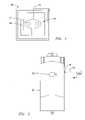
- FIG. 1illustrates an exemplary embodiment of a system 100 for reducing a penalty period for a distributed power train 101 traveling along a route 103 , such as a railroad, for example.
- the distributed power train 101includes a pair of lead or other first locomotives 105 , 106 , a remote locomotive 108 , and train cars 107 positioned between the lead locomotives 105 , 106 and the remote locomotive 108 .
- the lead locomotives 105 , 106may be communicatively coupled with trainline cables 109 , for example.
- the lead locomotive 106includes a lead braking system 111 and the remote locomotive 108 includes a remote braking system 113 .
- the braking system 111 , 113includes a fluid carrying brake pipe 110 , which extends the length of the distributed power train 101 , and connects the lead locomotive 106 and the remote locomotive 108 .
- FIG. 1illustrates a distributed power train having two lead locomotives and a single remote locomotive, this embodiment is merely exemplary, and the embodiments of the present invention may be applicable to a distributed power train having a varied arrangement of lead locomotives and/or remote locomotives. Also, as indicated above, embodiments of the present invention are applicable to any distributed power train having two or more locomotives, arbitrarily designated herein as a first locomotive and a remote locomotive.
- the first locomotiveis shown and described herein as being the lead locomotive in the train, but this is for illustration purposes only and is not meant to be limiting, unless otherwise specified.
- the braking systems 111 , 113are switched to the application state upon a reduction in a pressure in the brake pipe 110 below an application pressure, such as 64 PSIG (pounds per square inch gauge), for example.
- the braking systems 111 , 113are switched to the release state upon an increase in the pressure in the brake pipe 110 above a release pressure, such as 90 PSIG, for example.
- the braking systems 111 , 113may be switched from the release state to the application state by reducing the release pressure of 90 PSIG by 26 PSIG to below the application pressure of 64 PSIG.
- the numeric pressure thresholds discussed above in this exampleare merely exemplary, and the exact numeric pressure thresholds of application or release of the braking systems 111 , 113 may vary, based on the characteristics of the distributed power train 101 , for example.
- the distributed power train 101initiates a penalty brake application or operation, which lasts a minimum time period (the penalty period), such as 120 seconds, for example, in which the braking systems 111 , 113 are switched to the application state by lowering the pressure within the brake pipe 110 below the application pressure, such as below 64 PSIG, for example.
- a penalty brake applicationmay be automatically triggered and the brake pipe 110 pressure is lowered below the application pressure for the minimum time period.
- a penalty circumstance which may trigger a penalty periodinclude a failure in a component or a system within the distributed power train 101 and/or a speed of the distributed power train 101 exceeding a maximum speed threshold, as measured by a wayside device (not shown) adjacent to the route 103 , for example.
- the system 100includes sensors 112 , 114 positioned within the distributed power train 101 , to measure a parameter related to the operation of the respective braking system 111 , 113 .
- a fluid pressure sensor 112is coupled to the brake pipe 110 adjacent to the remote locomotive 108 , to measure a pressure within the brake pipe 110 adjacent to the remote locomotive 108 .
- a speed sensor 114is positioned on the distributed power train 101 , such as on the remote locomotive 108 , to measure a speed of the distributed power train 101 .
- An example of such a speed sensormay be an axle counter, which counts the number of rotations of the wheels of a locomotive, and, based on a known circumference of the wheels, can calculate the speed of the locomotive.
- the transceivers 126 , 127may be global positioning system (GPS) transceivers which are in communication with GPS satellites (not shown), to determine a location of the respective remote locomotive 108 and the lead locomotive 106 .
- GPSglobal positioning system
- the speed sensormay be a GPS speed sensor that is coupled to the GPS transceiver 126 , and determines the speed of the distributed power train 101 , based on the position information provided by the GPS transceiver 126 and time data provided by a clock, for example.
- the sensors 112 , 114are coupled to a remote processor 118 , positioned on the remote locomotive 108 .
- FIG. 1illustrates one pressure sensor and one speed sensor, each of which are positioned on the remote locomotive, the embodiments of the present invention are applicable for more than one pressure sensor and/or speed sensor, which may be positioned at a location other than the remote locomotive, for example.
- the system 100includes a lead processor 116 positioned within the lead locomotive 106 .
- Lead processorrefers to a processor in a lead locomotive, but this is merely an example.
- embodimentsare applicable, more generally, to a control processor in a first locomotive, that is, a processor configured to carry out one or more control functions of the first locomotive or train 101 .
- the processormay be specific to the braking system, specific to the penalty period reduction system, or it may be a processor used in the locomotive/train for multiple purposes.)
- the lead processor 116is coupled to the pressure sensor 112 and/or the speed sensor 114 (via the wireless link 128 to the remote processor 118 ), and receives the measured pressure and/or speed data from the pressure sensor 112 and/or the speed sensor 114 . Subsequent to a penalty circumstance, such as the linking between the lead locomotive 106 and the remote locomotive 108 , as discussed above, and the commencement of the penalty period, the lead processor 116 is configured to monitor the measured pressure of the brake pipe 110 and/or measured speed of the distributed power train 101 .
- the lead processor 116is configured to switch the braking system 111 , 113 from the application state into a release state, and reduce the minimum time period during which the application pressure in the brake pipe 110 is imposed.
- the distributed power train 101need not remain stationary with the braking systems 111 , 113 in the application state for the entire minimum time period, thereby reducing delays and improving the efficient operation of the distributed power train 101 .
- the lead locomotive 106includes a display 120 coupled to the lead processor 116 .
- the display 120is configured to output the measured pressure within the brake pipe 110 and the measured speed of the distributed power train 101 .
- the lead processor 116includes a memory 122 to store a respective predetermined safety range of the measured pressure within the brake pipe 110 , and a respective predetermined safety range of the measured speed of the distributed power train 101 .
- the lead processor 116monitors the measured pressure within the brake pipe 110 adjacent to the remote locomotive 108 and the measured speed of the distributed power train 101 , and determines whether the measured pressure and/or the measured speed are within the respective predetermined safety range of the measured pressure and the measured speed, provided by the memory 122 .
- the lead processor 116may transmit an output to the display 120 to prompt an operator of the lead locomotive 106 to switch the braking system 111 from the application state to the release state, as discussed in greater detail below.
- the predetermined safety range of the measured pressuremay be a pressure below the application pressure, such as a pressure below 64 PSIG, for example.
- the predetermined safety range of the measured speedmay be a speed below a low speed threshold that approaches or equals zero, as indicative that the distributed power train 101 has actually stopped, for example.
- the remote processor 118is communicatively coupled to the lead processor 116 over the wireless link 128 .
- the remote locomotive 108may include a memory unit 124 associated with the processor 118 .
- the respective braking system 111 , 113 of the lead locomotive 106 and the remote locomotive 108include a respective brake handle 130 , 132 , a respective brake valve 134 , 136 , and a respective brake processor 138 , 140 coupled to the respective brake handle 130 , 132 and the respective brake valve 134 , 136 .
- the respective brake processor 138 , 140moves the respective brake handle 130 , 132 to a suppression position and switches the respective brake valve 134 , 136 to a closed position.
- the pressure within the brake pipe 110is reduced below an application value, such as below 64 PSIG, and the respective brake processor 138 , 140 moves the respective brake handle 130 , 132 to the suppression position and switches the respective brake valve 134 , 136 to the closed position, in response thereto.
- the lead processor 116may transmit one or more of: a lead valve signal to the brake processor 138 of the lead locomotive 106 to move the brake valve 134 from the closed position to an open position; a signal to the display 120 to prompt the operator of the distributed power train 101 to switch the brake handle 130 from the suppression position to the release position; and/or a first release signal to the brake processor 138 of the lead locomotive 106 such that the braking system 111 of the lead locomotive 106 switches from the application state to the release state to initiate an increase in the pressure within the brake pipe 110 .
- the lead processor 116is further configured to transmit a second release signal to the remote processor 118 (over the wireless link 128 ) to switch the remote braking system 113 from the application state to the release state.
- the remote processor 118determines whether the measured pressure within the brake pipe 110 adjacent to the remote locomotive 108 has increased from the application value, such as 64 PSIG, for example.
- the remote processor 118transmits one or more of: a remote valve signal to the brake processor 140 of the remote locomotive 108 to move the brake valve 136 from the closed position to an open position; and/or a remote handle signal to the brake processor 140 of the remote locomotive 108 to switch the brake handle 132 from the suppression position to a release position. Subsequent to the brake processor 140 moving the brake valve 136 to the open position and switching the brake handle 132 to the release position, the braking system 113 of the remote locomotive 108 is switched from the application state to the release state, to permit an increase in the pressure in the brake pipe 110 .
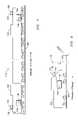
- FIG. 2illustrates an exemplary embodiment of a method 200 for reducing a penalty period of the distributed power train 101 .
- the steps of the method 200involve similar steps to those discussed in the embodiments of FIG. 1 above.
- the braking systems 111 , 113 of the distributed power train 101are switched to the application state, at 201 .
- the brake handle 130 , 132 or brake valve handle (BVH)is switched to the suppression position, at 202 .
- the lead processor 116then monitors the measured pressure within the brake pipe 110 , to determine if it is less than 64 PSIG, and also monitors the measured speed of the distributed power train 101 , to determine if is at zero or approaching zero, at 204 .
- the lead processor 116determines whether the lead brake handle 130 is still in the suppression position, at 204 . If all of these criteria are true, the method 200 involves a 5 second pause by the lead processor 116 and a verification that the remote brake handle 132 is in the suppression position, at 206 . If all of the criteria are not true, the method 200 initiates a 2-minute timer, at 208 , during which the pressure and speed are constantly compared with the above thresholds, and the lead brake handle 130 is checked as to whether it is in the suppression position. If, after the 2-minute period, the pressure and speed don't comply with the above thresholds (see 210 ), the method 200 continues to distinct steps for the lead locomotive 106 and the remote locomotive 108 , at 212 .
- the lead locomotive 106transmits a signal to the brake processor 138 , and awaits a response, to determine whether any functional failure exists in the braking system 111 (or EAB: electronic air brake), at 214 . If a functional failure in the braking system 111 exists, such as through a lack of a response from the brake processor 138 to the signal transmitted from the lead locomotive 106 , the distributed power train 101 remains in the penalty phase, at 218 .
- the lead processor 116moves the brake valve 134 from the closed position to the open position (or clears a penalty bit), and transmits an output to the display 120 to prompt an operator of the lead locomotive 106 to switch the brake handle 130 from the suppression position to the release position, at 216 , after which the lead processor 116 checks that the brake handle 130 has been moved from the suppression position to the release position, at 220 . If the brake handle 130 is not in the release position, the method 200 continues to check the brake handle 130 until it is in the release position.
- the lead processor 116then sends the first release signal (discussed above) to the brake processor 138 to release the braking system 111 , and sends the second release signal to the remote processor 118 , at 222 .
- the remote processor 118(or remote DPC: remote distributive power computer) moves the brake valve 136 from the closed position to the open position, switches the brake handle 132 to the release position, and releases the braking system 113 , at 224 .
- FIG. 3illustrates a flowchart depicting an exemplary embodiment of a method 300 for reducing a penalty period for the distributed power train 101 .
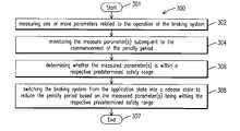
- the method 300includes measuring 302 one or more parameters related to the operation of the braking system 111 , 113 . (This may include parameters related directly to braking system operation, e.g., brake fluid pressure, and parameters relating to the effects of the braking system on the train or locomotive(s), such as train speed or acceleration levels, dynamic braking power output, or the like.)
- the method 300further includes monitoring 304 the measured parameter(s) subsequent to the commencement of the penalty period.
- the method 300further includes determining 306 whether the measured parameter(s) is within a respective predetermined safety range.
- the method 300further includes switching 308 the braking system 111 , 113 from the application state into a release state to reduce the penalty period based on the measured parameter(s) being within the respective predetermined safety range, before ending at 309 .
- Certain embodimentsmay be applicable to distributed power vehicle systems generally, meaning two or more powered vehicles that are linked together and controlled in concert to pull or otherwise move one or more non-powered load vehicles.
Landscapes
- Engineering & Computer Science (AREA)
- Transportation (AREA)
- Mechanical Engineering (AREA)
- Automation & Control Theory (AREA)
- Braking Systems And Boosters (AREA)
- Electric Propulsion And Braking For Vehicles (AREA)
- Valves And Accessory Devices For Braking Systems (AREA)
- Regulating Braking Force (AREA)
Abstract
Description
- Distributed power train operation involves the controlled coordination of motive power supplied from a lead locomotive and one or more remote locomotives spaced apart from the lead locomotive in a train consist. The lead and remote locomotives are linked together and controlled in concert to pull or otherwise move one or more non-powered load vehicles. Each lead and remote locomotive includes a braking processor for controlling the operations of a respective braking system and a communication system for exchanging information between the lead and remote locomotives over a communication link. A brake pipe fluidically interconnects each of the locomotives and rail cars of the train wherein modulation of a fluid flow, such as a fluid pressure in the brake pipe, is conventionally used to indicate desired braking operations. Remote locomotive braking operations may be controlled responsive to sensed brake pipe flow conditions at the respective remote locomotives.
- During the operation of a distributed power train, various circumstances may arise which trigger a “penalty brake” operation or application. Here, upon the occurrence of a designated stimulus, or based on certain operating conditions of the train (e.g., the train going over a designated speed limit, a determination that the train is in imminent threat of hitting another vehicle or other object, or the train passing a “stop” signal), a command is initiated for automatically causing the train's brake system in engage. That is, based upon the occurrence of certain conditions, operation of the train is “penalized” by automatically causing it to slow down and stop. The penalty brake application lasts a minimum time period (commonly referred to as the “penalty period”), such as 120 seconds, during which the fluid pressure within the brake pipe is minimized, causing a full application of the braking system to stop the train for the minimum time period. The minimum time period is arbitrarily set to ensure that the distributed power train has completely stopped prior to the end of the penalty period. The penalty period is mandatory and may be enforced by an outside agency, such as the Federal Railroad Administration (FRA), for example. Thus, upon the occurrence of a circumstance giving rise to a penalty brake application, the distributed power train is automatically stopped for the penalty period, irrespective of whether adequate safety conditions are present to indicate that the train has completely stopped prior to the end of the penalty period.
- Heretofore, the time length of a penalty period is mandatory and introduces noticeable delays and inefficient operation of a distributed power train, particularly when multiple penalty periods are triggered in succession. Thus, it would be advantageous to provide a system which improves the efficient operation of the distributed power train by reducing the duration of a penalty period by verifying that adequate safety conditions are present to indicate that the train has completely stopped.
- One embodiment of the present invention provides a system for reducing a penalty period for a distributed power train. The distributed power train includes a braking system that switches into an application state upon the commencement of the penalty period. The distributed power train includes a first locomotive and a remote locomotive. The braking system includes a fluid carrying brake pipe that connects the first locomotive and the remote locomotive. The system includes a sensor positioned within the distributed power train, which measures a parameter related to the operation of the braking system. A control processor is positioned within the first locomotive, and is coupled to the sensor. Subsequent to the commencement of the penalty period, the control processor monitors the measured parameter and switches the braking system from the application state into a release state to reduce the penalty period, based on the measured parameter being within a predetermined safety range. (Here, the first locomotive may be a lead locomotive, but is not limited in this regard. Thus, “first” is an arbitrary designation for distinguishing the first locomotive from the remote locomotive or other vehicles, it being recognized that the functionality of the present invention need not necessarily be embodied solely in a lead locomotive. “Remote” is also an arbitrary designation that refers to another locomotive other than the first locomotive. Thus, the remote locomotive may be contiguous with the first locomotive or separated there from by one or more other locomotives and/or non-locomotive rail cars.)
- Another embodiment of the present invention provides a system for reducing a penalty period for a distributed power train. The system includes the distributed power train having a first locomotive and a remote locomotive. Additionally, the system includes a braking system, which switches into an application state upon the commencement of the penalty period. The braking system includes a fluid carrying brake pipe that connects the first locomotive and the remote locomotive. The system further includes a sensor positioned within the distributed power train, to measure a parameter related to the operation of the braking system. Subsequent to the commencement of the penalty period, the braking system switches from the application state into a release state to reduce the penalty period, based on the measured parameter being within a predetermined safety range.
- Another embodiment of the present invention provides a method for reducing a penalty period for a distributed power train. The distributed power train includes a braking system, which switches into an application state upon commencement of the penalty period. The distributed power train includes a first locomotive and a remote locomotive. The braking system includes a fluid carrying brake pipe that connects the first locomotive and the remote locomotive. The method includes measuring a parameter related to the operation of the braking system, and monitoring the measured parameter subsequent to the commencement of the penalty period. Additionally, the method includes determining whether the measured parameter falls within a predetermined safety range. The method further includes switching the braking system from the application state into a release state to reduce the penalty period, based on the measured parameter falling within the predetermined safety range.
FIG. 1 is a schematic diagram of a distributed power train utilized in an exemplary embodiment of a system for reducing a penalty period of the distributed power train;FIG. 2 is a flow chart of an exemplary embodiment of a method for reducing a penalty period of the distributed power train; andFIG. 3 is a flow chart of an exemplary embodiment of a method for reducing a penalty period of the distributed power train.- The present inventors have observed that, during distributed power train operations, noticeable delays and inefficiencies are introduced during certain penalty brake applications, when the braking system is switched into the full application state for the minimum time period (penalty period), in an effort to ensure that the train has stopped. The inventors have recognized that various parameters related to the operation of the braking system may be monitored, to indicate whether or not the distributed power train has stopped, and thus reduce the penalty period by switching the braking system to the release state prior to the end of the penalty period. The pressure within the brake pipe of the distributed power train is an example of such a monitored parameter. A discussion of the measurement and monitoring of the brake pipe pressure within a distributed power train is discussed in U.S. Patent Publication No. 2007/0236078, filed on Apr. 10, 2006, and assigned to the assignee of the present application, which is incorporated by reference herein in its entirety.
FIG. 1 illustrates an exemplary embodiment of asystem 100 for reducing a penalty period for adistributed power train 101 traveling along aroute 103, such as a railroad, for example. Thedistributed power train 101 includes a pair of lead or otherfirst locomotives remote locomotive 108, andtrain cars 107 positioned between thelead locomotives remote locomotive 108. Thelead locomotives trainline cables 109, for example. Thelead locomotive 106 includes alead braking system 111 and theremote locomotive 108 includes aremote braking system 113. Thebraking system carrying brake pipe 110, which extends the length of thedistributed power train 101, and connects thelead locomotive 106 and theremote locomotive 108. AlthoughFIG. 1 illustrates a distributed power train having two lead locomotives and a single remote locomotive, this embodiment is merely exemplary, and the embodiments of the present invention may be applicable to a distributed power train having a varied arrangement of lead locomotives and/or remote locomotives. Also, as indicated above, embodiments of the present invention are applicable to any distributed power train having two or more locomotives, arbitrarily designated herein as a first locomotive and a remote locomotive. The first locomotive is shown and described herein as being the lead locomotive in the train, but this is for illustration purposes only and is not meant to be limiting, unless otherwise specified.- As discussed above in regards to certain embodiments of the present invention, the
braking systems brake pipe 110 below an application pressure, such as 64 PSIG (pounds per square inch gauge), for example. Thebraking systems brake pipe 110 above a release pressure, such as 90 PSIG, for example. For example, thebraking systems braking systems distributed power train 101, for example. - During any of a number of penalty circumstances, the
distributed power train 101 initiates a penalty brake application or operation, which lasts a minimum time period (the penalty period), such as 120 seconds, for example, in which thebraking systems brake pipe 110 below the application pressure, such as below 64 PSIG, for example. For example, when thelead locomotive 106 and theremote locomotive 108 are linked through awireless link 128 communicated through arespective transceiver remote locomotive 108 and thelead locomotive 106, a penalty brake application may be automatically triggered and thebrake pipe 110 pressure is lowered below the application pressure for the minimum time period. Other examples of a penalty circumstance which may trigger a penalty period include a failure in a component or a system within thedistributed power train 101 and/or a speed of thedistributed power train 101 exceeding a maximum speed threshold, as measured by a wayside device (not shown) adjacent to theroute 103, for example. Numerous other examples of penalty circumstances exist, all of which involve a mandatory reduction in thebrake pipe 110 pressure below the application pressure for the minimum time period. - As further illustrated in the exemplary embodiment of
FIG. 1 , thesystem 100 includessensors power train 101, to measure a parameter related to the operation of therespective braking system fluid pressure sensor 112 is coupled to thebrake pipe 110 adjacent to theremote locomotive 108, to measure a pressure within thebrake pipe 110 adjacent to theremote locomotive 108. Additionally, aspeed sensor 114 is positioned on the distributedpower train 101, such as on theremote locomotive 108, to measure a speed of the distributedpower train 101. An example of such a speed sensor may be an axle counter, which counts the number of rotations of the wheels of a locomotive, and, based on a known circumference of the wheels, can calculate the speed of the locomotive. In addition to being used for communicating with one another over thewireless link 128, thetransceivers remote locomotive 108 and thelead locomotive 106. The speed sensor may be a GPS speed sensor that is coupled to theGPS transceiver 126, and determines the speed of the distributedpower train 101, based on the position information provided by theGPS transceiver 126 and time data provided by a clock, for example. Thesensors remote processor 118, positioned on theremote locomotive 108. AlthoughFIG. 1 illustrates one pressure sensor and one speed sensor, each of which are positioned on the remote locomotive, the embodiments of the present invention are applicable for more than one pressure sensor and/or speed sensor, which may be positioned at a location other than the remote locomotive, for example. - As further illustrated in the exemplary embodiment of
FIG. 1 , thesystem 100 includes alead processor 116 positioned within thelead locomotive 106. (“Lead” processor refers to a processor in a lead locomotive, but this is merely an example. As mentioned above, embodiments are applicable, more generally, to a control processor in a first locomotive, that is, a processor configured to carry out one or more control functions of the first locomotive ortrain 101. The processor may be specific to the braking system, specific to the penalty period reduction system, or it may be a processor used in the locomotive/train for multiple purposes.) Thelead processor 116 is coupled to thepressure sensor 112 and/or the speed sensor114 (via thewireless link 128 to the remote processor118), and receives the measured pressure and/or speed data from thepressure sensor 112 and/or thespeed sensor 114. Subsequent to a penalty circumstance, such as the linking between thelead locomotive 106 and theremote locomotive 108, as discussed above, and the commencement of the penalty period, thelead processor 116 is configured to monitor the measured pressure of thebrake pipe 110 and/or measured speed of the distributedpower train 101. Based on the measured pressure in thebrake pipe 110 and/or the measured speed of the distributedpower train 101, thelead processor 116 is configured to switch thebraking system brake pipe 110 is imposed. Thus, the distributedpower train 101 need not remain stationary with thebraking systems power train 101. - As illustrated in the exemplary embodiment of
FIG. 1 , thelead locomotive 106 includes adisplay 120 coupled to thelead processor 116. Thedisplay 120 is configured to output the measured pressure within thebrake pipe 110 and the measured speed of the distributedpower train 101. Thelead processor 116 includes amemory 122 to store a respective predetermined safety range of the measured pressure within thebrake pipe 110, and a respective predetermined safety range of the measured speed of the distributedpower train 101. Thelead processor 116 monitors the measured pressure within thebrake pipe 110 adjacent to theremote locomotive 108 and the measured speed of the distributedpower train 101, and determines whether the measured pressure and/or the measured speed are within the respective predetermined safety range of the measured pressure and the measured speed, provided by thememory 122. Subsequent to determining that the measured pressure and/or the measured speed are within the respective predetermined safety range, thelead processor 116 may transmit an output to thedisplay 120 to prompt an operator of thelead locomotive 106 to switch thebraking system 111 from the application state to the release state, as discussed in greater detail below. In an exemplary embodiment, the predetermined safety range of the measured pressure may be a pressure below the application pressure, such as a pressure below 64 PSIG, for example. In another exemplary embodiment, the predetermined safety range of the measured speed may be a speed below a low speed threshold that approaches or equals zero, as indicative that the distributedpower train 101 has actually stopped, for example. - As further illustrated in
FIG. 1 , theremote processor 118 is communicatively coupled to thelead processor 116 over thewireless link 128. (Theremote locomotive 108 may include amemory unit 124 associated with theprocessor 118.) Therespective braking system lead locomotive 106 and theremote locomotive 108 include a respective brake handle130,132, arespective brake valve respective brake processor respective brake valve respective brake processor respective brake valve brake pipe 110 is reduced below an application value, such as below 64 PSIG, and therespective brake processor respective brake valve - Subsequent to determining that the measured pressure and/or the measured speed falls within the respective predetermined safety range, the
lead processor 116 may transmit one or more of: a lead valve signal to thebrake processor 138 of thelead locomotive 106 to move thebrake valve 134 from the closed position to an open position; a signal to thedisplay 120 to prompt the operator of the distributedpower train 101 to switch the brake handle130 from the suppression position to the release position; and/or a first release signal to thebrake processor 138 of thelead locomotive 106 such that thebraking system 111 of thelead locomotive 106 switches from the application state to the release state to initiate an increase in the pressure within thebrake pipe 110. Subsequent to the first release signal, thelead processor 116 is further configured to transmit a second release signal to the remote processor118 (over the wireless link128) to switch theremote braking system 113 from the application state to the release state. As illustrated inFIG. 1 , subsequent to receiving the second release signal from thelead processor 116, theremote processor 118 determines whether the measured pressure within thebrake pipe 110 adjacent to theremote locomotive 108 has increased from the application value, such as 64 PSIG, for example. If the pressure within thebrake pipe 110 has increased from the application value, theremote processor 118 transmits one or more of: a remote valve signal to thebrake processor 140 of theremote locomotive 108 to move thebrake valve 136 from the closed position to an open position; and/or a remote handle signal to thebrake processor 140 of theremote locomotive 108 to switch the brake handle132 from the suppression position to a release position. Subsequent to thebrake processor 140 moving thebrake valve 136 to the open position and switching the brake handle132 to the release position, thebraking system 113 of theremote locomotive 108 is switched from the application state to the release state, to permit an increase in the pressure in thebrake pipe 110. FIG. 2 illustrates an exemplary embodiment of amethod 200 for reducing a penalty period of the distributedpower train 101. The steps of themethod 200 involve similar steps to those discussed in the embodiments ofFIG. 1 above. As previously stated, upon the occurrence of a penalty circumstance, thebraking systems power train 101 are switched to the application state, at201. Additionally, as discussed above, thebrake handle lead processor 116 then monitors the measured pressure within thebrake pipe 110, to determine if it is less than 64 PSIG, and also monitors the measured speed of the distributedpower train 101, to determine if is at zero or approaching zero, at204. Additionally, thelead processor 116 determines whether the lead brake handle130 is still in the suppression position, at204. If all of these criteria are true, themethod 200 involves a 5 second pause by thelead processor 116 and a verification that theremote brake handle 132 is in the suppression position, at206. If all of the criteria are not true, themethod 200 initiates a 2-minute timer, at208, during which the pressure and speed are constantly compared with the above thresholds, and the lead brake handle130 is checked as to whether it is in the suppression position. If, after the 2-minute period, the pressure and speed don't comply with the above thresholds (see210), themethod 200 continues to distinct steps for thelead locomotive 106 and theremote locomotive 108, at212. Thelead locomotive 106 transmits a signal to thebrake processor 138, and awaits a response, to determine whether any functional failure exists in the braking system111 (or EAB: electronic air brake), at214. If a functional failure in thebraking system 111 exists, such as through a lack of a response from thebrake processor 138 to the signal transmitted from thelead locomotive 106, the distributedpower train 101 remains in the penalty phase, at218. If no failures in thebraking system 111 are detected, the lead processor116 (or lead DPC: lead distributive power computer) moves thebrake valve 134 from the closed position to the open position (or clears a penalty bit), and transmits an output to thedisplay 120 to prompt an operator of thelead locomotive 106 to switch the brake handle130 from the suppression position to the release position, at216, after which thelead processor 116 checks that thebrake handle 130 has been moved from the suppression position to the release position, at220. If thebrake handle 130 is not in the release position, themethod 200 continues to check the brake handle130 until it is in the release position. Thelead processor 116 then sends the first release signal (discussed above) to thebrake processor 138 to release thebraking system 111, and sends the second release signal to theremote processor 118, at222. Upon receiving the second release signal, the remote processor118 (or remote DPC: remote distributive power computer) moves thebrake valve 136 from the closed position to the open position, switches the brake handle132 to the release position, and releases thebraking system 113, at224.FIG. 3 illustrates a flowchart depicting an exemplary embodiment of amethod 300 for reducing a penalty period for the distributedpower train 101. Themethod 300 includes measuring302 one or more parameters related to the operation of thebraking system method 300 further includes monitoring304 the measured parameter(s) subsequent to the commencement of the penalty period. Themethod 300 further includes determining306 whether the measured parameter(s) is within a respective predetermined safety range. Themethod 300 further includes switching308 thebraking system - Certain embodiments may be applicable to distributed power vehicle systems generally, meaning two or more powered vehicles that are linked together and controlled in concert to pull or otherwise move one or more non-powered load vehicles.
- While various embodiments of the present invention have been shown and described herein, it will be obvious that such embodiments are provided by way of example only. Numerous variations, changes and substitutions may be made without departing from the invention herein. For example, the method and system described herein may be applied to any transportation system comprising members interconnected by a fluidic brake pipe such as a train, a semi-truck with trailers, etc. Accordingly, it is intended that the invention be limited only by the spirit and scope of the appended claims.
Claims (17)
Priority Applications (8)
| Application Number | Priority Date | Filing Date | Title |
|---|---|---|---|
| US12/249,503US8190313B2 (en) | 2008-10-10 | 2008-10-10 | System and method for reducing a penalty period for a distributed power train |
| PCT/US2009/057643WO2010042309A2 (en) | 2008-10-10 | 2009-09-21 | System and method for reducing a penalty period for a distributed power train |
| BRPI0914090ABRPI0914090A2 (en) | 2008-10-10 | 2009-09-21 | reduction system and method for reducing a penalty period for a distributed power train |
| EA201100454AEA021793B1 (en) | 2008-10-10 | 2009-09-21 | Method for controlling braking system of a transport system |
| AU2009302752AAU2009302752A1 (en) | 2008-10-10 | 2009-09-21 | System and method for reducing a penalty period for a distributed power train |
| DE112009002305TDE112009002305T5 (en) | 2008-10-10 | 2009-09-21 | System and method for reducing a forced time for a train with distributed drive power |
| CN200980140605.8ACN102177056B (en) | 2008-10-10 | 2009-09-21 | For shortening the system and method for the punishment phase of distributed power train |
| US13/458,719US8589000B2 (en) | 2008-10-10 | 2012-04-27 | System and method for reducing a penalty period for a vehicle |
Applications Claiming Priority (1)
| Application Number | Priority Date | Filing Date | Title |
|---|---|---|---|
| US12/249,503US8190313B2 (en) | 2008-10-10 | 2008-10-10 | System and method for reducing a penalty period for a distributed power train |
Related Child Applications (1)
| Application Number | Title | Priority Date | Filing Date |
|---|---|---|---|
| US13/458,719ContinuationUS8589000B2 (en) | 2008-10-10 | 2012-04-27 | System and method for reducing a penalty period for a vehicle |
Publications (2)
| Publication Number | Publication Date |
|---|---|
| US20100094489A1true US20100094489A1 (en) | 2010-04-15 |
| US8190313B2 US8190313B2 (en) | 2012-05-29 |
Family
ID=42099641
Family Applications (2)
| Application Number | Title | Priority Date | Filing Date |
|---|---|---|---|
| US12/249,503Expired - Fee RelatedUS8190313B2 (en) | 2008-10-10 | 2008-10-10 | System and method for reducing a penalty period for a distributed power train |
| US13/458,719ActiveUS8589000B2 (en) | 2008-10-10 | 2012-04-27 | System and method for reducing a penalty period for a vehicle |
Family Applications After (1)
| Application Number | Title | Priority Date | Filing Date |
|---|---|---|---|
| US13/458,719ActiveUS8589000B2 (en) | 2008-10-10 | 2012-04-27 | System and method for reducing a penalty period for a vehicle |
Country Status (7)
| Country | Link |
|---|---|
| US (2) | US8190313B2 (en) |
| CN (1) | CN102177056B (en) |
| AU (1) | AU2009302752A1 (en) |
| BR (1) | BRPI0914090A2 (en) |
| DE (1) | DE112009002305T5 (en) |
| EA (1) | EA021793B1 (en) |
| WO (1) | WO2010042309A2 (en) |
Cited By (10)
| Publication number | Priority date | Publication date | Assignee | Title |
|---|---|---|---|---|
| US20140174316A1 (en)* | 2012-12-20 | 2014-06-26 | Emd | Brake Control System Having Independent Power Supply |
| JP2014523831A (en)* | 2011-07-04 | 2014-09-18 | クノール−ブレムゼ レール システムス (ユーケー) リミテッド | Brake system |
| US20150083529A1 (en)* | 2013-09-26 | 2015-03-26 | Faiveley Transport Italia S.P.A. | Pneumatic brake system redundancy in locomotive consists |
| EP2511146A3 (en)* | 2011-03-22 | 2015-06-03 | ÖBB - Technische Services GmbH | Automatic brake monitoring |
| WO2016114902A1 (en)* | 2015-01-12 | 2016-07-21 | Smartdrive Systems, Inc. | Rail vehicle event triggering system and method |
| US9487222B2 (en) | 2015-01-08 | 2016-11-08 | Smartdrive Systems, Inc. | System and method for aggregation display and analysis of rail vehicle event information |
| US9663127B2 (en) | 2014-10-28 | 2017-05-30 | Smartdrive Systems, Inc. | Rail vehicle event detection and recording system |
| US9902410B2 (en) | 2015-01-08 | 2018-02-27 | Smartdrive Systems, Inc. | System and method for synthesizing rail vehicle event information |
| US11208125B2 (en)* | 2016-08-08 | 2021-12-28 | Transportation Ip Holdings, Llc | Vehicle control system |
| US11265284B2 (en) | 2016-03-18 | 2022-03-01 | Westinghouse Air Brake Technologies Corporation | Communication status system and method |
Families Citing this family (10)
| Publication number | Priority date | Publication date | Assignee | Title |
|---|---|---|---|---|
| US9033285B2 (en)* | 2013-03-14 | 2015-05-19 | Union Pacific Railroad Company | Containerized locomotive distributed power control |
| US9227639B1 (en) | 2014-07-09 | 2016-01-05 | General Electric Company | System and method for decoupling a vehicle system |
| US9925992B2 (en) | 2014-10-15 | 2018-03-27 | General Electric Company | System and method for communicating in a vehicle consist |
| RU2616759C2 (en)* | 2015-04-08 | 2017-04-18 | Общество С Ограниченной Ответственностью "Авп Технология" | Vehicle onboard devices parameters monitoring device |
| US9731690B2 (en)* | 2015-04-30 | 2017-08-15 | Electro-Motive Diesel, Inc. | Automatic braking system |
| CN105059280A (en)* | 2015-09-14 | 2015-11-18 | 南车资阳机车有限公司 | Electronic control punishment braking system and braking method |
| US9776649B1 (en)* | 2016-03-24 | 2017-10-03 | New York Air Brake, LLC | Adaptive penalty braking for locomotive air brake system |
| US10482801B2 (en)* | 2017-03-22 | 2019-11-19 | Solera Holdings, Inc. | Start and stop methods for a vehicle smart mirror |
| CA3085567A1 (en)* | 2017-06-29 | 2019-01-03 | Westinghouse Air Brake Technologies Corporation | Ecp dumper braking |
| CN110962827B (en)* | 2018-09-30 | 2022-03-22 | 株洲中车时代电气股份有限公司 | Train brake release keeping method and device, network controller and train |
Citations (18)
| Publication number | Priority date | Publication date | Assignee | Title |
|---|---|---|---|---|
| US4626039A (en)* | 1985-02-22 | 1986-12-02 | American Standard Inc. | Railway vehicle penalty brake control system |
| US4971398A (en)* | 1989-09-05 | 1990-11-20 | General Signal Corporation | Suppression control of cab signal automated brake application |
| US5020862A (en)* | 1989-09-27 | 1991-06-04 | American Standard Inc. | Penalty brake control system |
| US5249125A (en)* | 1989-12-08 | 1993-09-28 | Knorr Brake Holding Corporation | Computer controlled railway brake equipment |
| US5507457A (en)* | 1995-02-13 | 1996-04-16 | Pulse Electronics, Inc. | Train integrity detection system |
| US5549363A (en)* | 1994-07-22 | 1996-08-27 | Westinghouse Air Brake Company | Railway braking apparatus |
| US5866811A (en)* | 1995-07-20 | 1999-02-02 | Westinghouse Air Brake Co. | End of train device |
| US6042201A (en)* | 1998-01-29 | 2000-03-28 | New York Air Brake Corporation | Penalty brake reduction in computer controlled train brake system |
| US6126247A (en)* | 1998-03-10 | 2000-10-03 | Westinghouse Air Brake Company | Computer control of railroad train brake system operation |
| US6275165B1 (en)* | 1998-03-19 | 2001-08-14 | Westinghouse Air Brake Company | A.A.R. compliant electronic braking system |
| US6401015B1 (en)* | 1997-10-14 | 2002-06-04 | Scot Stewart | Distributed power and electronic air brake control system for a train and associated methods |
| US6435623B1 (en)* | 1997-10-10 | 2002-08-20 | Ge Harris Railway Electronics, Llc | Valve assembly for electrically controlled pneumatic brakes |
| US20030107262A1 (en)* | 2001-12-10 | 2003-06-12 | Smith Eugene A. | Locomotive brake pipe valve cut-out failure detection and correction |
| US6671591B2 (en)* | 2001-06-04 | 2003-12-30 | General Electric Company | System and method for monitoring locomotive operation |
| US6759951B2 (en)* | 2001-11-16 | 2004-07-06 | General Electric Company | Method and system for communicating among a plurality of mobile assets |
| US6862502B2 (en)* | 2002-05-15 | 2005-03-01 | General Electric Company | Intelligent communications, command, and control system for a land-based vehicle |
| US20050189815A1 (en)* | 2004-02-27 | 2005-09-01 | Bryant Robert F. | Method and apparatus for swapping lead and remote locomotives in a distributed power railroad train |
| US7395141B1 (en)* | 2007-09-12 | 2008-07-01 | General Electric Company | Distributed train control |
Family Cites Families (6)
| Publication number | Priority date | Publication date | Assignee | Title |
|---|---|---|---|---|
| US5172316A (en) | 1989-12-08 | 1992-12-15 | New York Air Brake | Computer controlled railway brake equipment |
| US5720455A (en)* | 1996-11-13 | 1998-02-24 | Westinghouse Air Brake Company | Intra-train radio communication system |
| IT1303100B1 (en) | 1998-07-31 | 2000-10-30 | Sab Wabco Spa | CONTROL AND COMMUNICATION SYSTEM FOR RAILWAY CONVEYS. |
| US6371575B1 (en)* | 1999-07-16 | 2002-04-16 | New York Air Brake Corporation | Vigilance system |
| US6443538B1 (en) | 2000-12-29 | 2002-09-03 | Ge Harris Railway Electronics, Llc | Feed valve and reference pressure enhancement |
| US7628458B2 (en)* | 2006-04-10 | 2009-12-08 | General Electric Company | Adaptive brake flow masking at remote locomotives of a distributed power train |
- 2008
- 2008-10-10USUS12/249,503patent/US8190313B2/ennot_activeExpired - Fee Related
- 2009
- 2009-09-21CNCN200980140605.8Apatent/CN102177056B/ennot_activeExpired - Fee Related
- 2009-09-21AUAU2009302752Apatent/AU2009302752A1/ennot_activeAbandoned
- 2009-09-21WOPCT/US2009/057643patent/WO2010042309A2/enactiveApplication Filing
- 2009-09-21EAEA201100454Apatent/EA021793B1/ennot_activeIP Right Cessation
- 2009-09-21BRBRPI0914090Apatent/BRPI0914090A2/ennot_activeIP Right Cessation
- 2009-09-21DEDE112009002305Tpatent/DE112009002305T5/ennot_activeWithdrawn
- 2012
- 2012-04-27USUS13/458,719patent/US8589000B2/enactiveActive
Patent Citations (18)
| Publication number | Priority date | Publication date | Assignee | Title |
|---|---|---|---|---|
| US4626039A (en)* | 1985-02-22 | 1986-12-02 | American Standard Inc. | Railway vehicle penalty brake control system |
| US4971398A (en)* | 1989-09-05 | 1990-11-20 | General Signal Corporation | Suppression control of cab signal automated brake application |
| US5020862A (en)* | 1989-09-27 | 1991-06-04 | American Standard Inc. | Penalty brake control system |
| US5249125A (en)* | 1989-12-08 | 1993-09-28 | Knorr Brake Holding Corporation | Computer controlled railway brake equipment |
| US5549363A (en)* | 1994-07-22 | 1996-08-27 | Westinghouse Air Brake Company | Railway braking apparatus |
| US5507457A (en)* | 1995-02-13 | 1996-04-16 | Pulse Electronics, Inc. | Train integrity detection system |
| US5866811A (en)* | 1995-07-20 | 1999-02-02 | Westinghouse Air Brake Co. | End of train device |
| US6435623B1 (en)* | 1997-10-10 | 2002-08-20 | Ge Harris Railway Electronics, Llc | Valve assembly for electrically controlled pneumatic brakes |
| US6401015B1 (en)* | 1997-10-14 | 2002-06-04 | Scot Stewart | Distributed power and electronic air brake control system for a train and associated methods |
| US6042201A (en)* | 1998-01-29 | 2000-03-28 | New York Air Brake Corporation | Penalty brake reduction in computer controlled train brake system |
| US6126247A (en)* | 1998-03-10 | 2000-10-03 | Westinghouse Air Brake Company | Computer control of railroad train brake system operation |
| US6275165B1 (en)* | 1998-03-19 | 2001-08-14 | Westinghouse Air Brake Company | A.A.R. compliant electronic braking system |
| US6671591B2 (en)* | 2001-06-04 | 2003-12-30 | General Electric Company | System and method for monitoring locomotive operation |
| US6759951B2 (en)* | 2001-11-16 | 2004-07-06 | General Electric Company | Method and system for communicating among a plurality of mobile assets |
| US20030107262A1 (en)* | 2001-12-10 | 2003-06-12 | Smith Eugene A. | Locomotive brake pipe valve cut-out failure detection and correction |
| US6862502B2 (en)* | 2002-05-15 | 2005-03-01 | General Electric Company | Intelligent communications, command, and control system for a land-based vehicle |
| US20050189815A1 (en)* | 2004-02-27 | 2005-09-01 | Bryant Robert F. | Method and apparatus for swapping lead and remote locomotives in a distributed power railroad train |
| US7395141B1 (en)* | 2007-09-12 | 2008-07-01 | General Electric Company | Distributed train control |
Cited By (13)
| Publication number | Priority date | Publication date | Assignee | Title |
|---|---|---|---|---|
| EP2511146A3 (en)* | 2011-03-22 | 2015-06-03 | ÖBB - Technische Services GmbH | Automatic brake monitoring |
| JP2014523831A (en)* | 2011-07-04 | 2014-09-18 | クノール−ブレムゼ レール システムス (ユーケー) リミテッド | Brake system |
| US20140174316A1 (en)* | 2012-12-20 | 2014-06-26 | Emd | Brake Control System Having Independent Power Supply |
| US20150083529A1 (en)* | 2013-09-26 | 2015-03-26 | Faiveley Transport Italia S.P.A. | Pneumatic brake system redundancy in locomotive consists |
| US9868454B2 (en)* | 2013-09-26 | 2018-01-16 | FAIVELEY TRANSPORT ITALIA S. p. A. | Pneumatic brake system redundancy in locomotive consists |
| US9663127B2 (en) | 2014-10-28 | 2017-05-30 | Smartdrive Systems, Inc. | Rail vehicle event detection and recording system |
| US9487222B2 (en) | 2015-01-08 | 2016-11-08 | Smartdrive Systems, Inc. | System and method for aggregation display and analysis of rail vehicle event information |
| US9902410B2 (en) | 2015-01-08 | 2018-02-27 | Smartdrive Systems, Inc. | System and method for synthesizing rail vehicle event information |
| US9981674B1 (en) | 2015-01-08 | 2018-05-29 | Smartdrive Systems, Inc. | System and method for aggregation display and analysis of rail vehicle event information |
| WO2016114902A1 (en)* | 2015-01-12 | 2016-07-21 | Smartdrive Systems, Inc. | Rail vehicle event triggering system and method |
| US9908546B2 (en) | 2015-01-12 | 2018-03-06 | Smartdrive Systems, Inc. | Rail vehicle event triggering system and method |
| US11265284B2 (en) | 2016-03-18 | 2022-03-01 | Westinghouse Air Brake Technologies Corporation | Communication status system and method |
| US11208125B2 (en)* | 2016-08-08 | 2021-12-28 | Transportation Ip Holdings, Llc | Vehicle control system |
Also Published As
| Publication number | Publication date |
|---|---|
| CN102177056A (en) | 2011-09-07 |
| US20130179048A1 (en) | 2013-07-11 |
| CN102177056B (en) | 2015-09-23 |
| AU2009302752A1 (en) | 2010-04-15 |
| WO2010042309A2 (en) | 2010-04-15 |
| WO2010042309A3 (en) | 2011-03-24 |
| EA021793B1 (en) | 2015-09-30 |
| DE112009002305T5 (en) | 2012-01-19 |
| US8190313B2 (en) | 2012-05-29 |
| BRPI0914090A2 (en) | 2015-10-27 |
| US8589000B2 (en) | 2013-11-19 |
| EA201100454A1 (en) | 2011-10-31 |
Similar Documents
| Publication | Publication Date | Title |
|---|---|---|
| US8190313B2 (en) | System and method for reducing a penalty period for a distributed power train | |
| US8500214B2 (en) | System and method for control of distributed power rail vehicle | |
| CA2421190C (en) | Automatic coupling of locomotive to railcars | |
| CA2719838C (en) | Method and system for determining brake shoe effectiveness | |
| AU2013257257B2 (en) | Brake monitoring system for an air brake arrangement | |
| US9403517B2 (en) | System and method for determining air propagation data in a braking arrangement of a train | |
| US9592815B2 (en) | Train brake safety monitoring and fault action system | |
| JP2020516525A (en) | Support of train central management system by online transmission of information about braking ability | |
| BR122020023337B1 (en) | PARKING VERIFICATION SYSTEM AND METHOD FOR A TRAIN | |
| KR20140134708A (en) | Method for controlling a drive and brake device of a vehicle having a friction brake | |
| CA2984423C (en) | Train brake safety monitoring and fault action system | |
| CN108290589A (en) | The control system with adhesion figure for rail vehicle | |
| EP1226057A1 (en) | Eot service brake assist without radio communications |
Legal Events
| Date | Code | Title | Description |
|---|---|---|---|
| AS | Assignment | Owner name:GENERAL ELECTRIC COMPANY,NEW YORK Free format text:ASSIGNMENT OF ASSIGNORS INTEREST;ASSIGNORS:MOFFITT, ROBERT LYN;COX, LOUIS;REEL/FRAME:021668/0157 Effective date:20080828 Owner name:GENERAL ELECTRIC COMPANY, NEW YORK Free format text:ASSIGNMENT OF ASSIGNORS INTEREST;ASSIGNORS:MOFFITT, ROBERT LYN;COX, LOUIS;REEL/FRAME:021668/0157 Effective date:20080828 | |
| ZAAA | Notice of allowance and fees due | Free format text:ORIGINAL CODE: NOA | |
| ZAAB | Notice of allowance mailed | Free format text:ORIGINAL CODE: MN/=. | |
| STCF | Information on status: patent grant | Free format text:PATENTED CASE | |
| FPAY | Fee payment | Year of fee payment:4 | |
| AS | Assignment | Owner name:GE GLOBAL SOURCING LLC, CONNECTICUT Free format text:ASSIGNMENT OF ASSIGNORS INTEREST;ASSIGNOR:GENERAL ELECTRIC COMPANY;REEL/FRAME:047736/0140 Effective date:20181101 | |
| MAFP | Maintenance fee payment | Free format text:PAYMENT OF MAINTENANCE FEE, 8TH YEAR, LARGE ENTITY (ORIGINAL EVENT CODE: M1552); ENTITY STATUS OF PATENT OWNER: LARGE ENTITY Year of fee payment:8 | |
| FEPP | Fee payment procedure | Free format text:MAINTENANCE FEE REMINDER MAILED (ORIGINAL EVENT CODE: REM.); ENTITY STATUS OF PATENT OWNER: LARGE ENTITY | |
| STCH | Information on status: patent discontinuation | Free format text:PATENT EXPIRED DUE TO NONPAYMENT OF MAINTENANCE FEES UNDER 37 CFR 1.362 | |
| FP | Lapsed due to failure to pay maintenance fee | Effective date:20240529 |