US20100071382A1 - Gas Turbine Transition Duct - Google Patents
Gas Turbine Transition DuctDownload PDFInfo
- Publication number
- US20100071382A1 US20100071382A1US12/338,401US33840108AUS2010071382A1US 20100071382 A1US20100071382 A1US 20100071382A1US 33840108 AUS33840108 AUS 33840108AUS 2010071382 A1US2010071382 A1US 2010071382A1
- Authority
- US
- United States
- Prior art keywords
- wall
- cooling fluid
- transition member
- radially
- spanning members
- Prior art date
- Legal status (The legal status is an assumption and is not a legal conclusion. Google has not performed a legal analysis and makes no representation as to the accuracy of the status listed.)
- Granted
Links
- 230000007704transitionEffects0.000titleclaimsabstractdescription71
- 239000012809cooling fluidSubstances0.000claimsabstractdescription73
- 238000002485combustion reactionMethods0.000claimsabstractdescription9
- 238000004891communicationMethods0.000claimsabstractdescription8
- 239000000567combustion gasSubstances0.000claimsdescription38
- 239000012720thermal barrier coatingSubstances0.000claimsdescription12
- 239000007789gasSubstances0.000claimsdescription9
- 238000001816coolingMethods0.000description25
- 239000003570airSubstances0.000description11
- 239000010408filmSubstances0.000description10
- 239000000463materialSubstances0.000description10
- 238000000034methodMethods0.000description7
- 238000009792diffusion processMethods0.000description5
- 229910001026inconelInorganic materials0.000description4
- 238000003466weldingMethods0.000description3
- 229910045601alloyInorganic materials0.000description2
- 239000000956alloySubstances0.000description2
- 230000000712assemblyEffects0.000description2
- 238000000429assemblyMethods0.000description2
- 239000000446fuelSubstances0.000description2
- 229910052751metalInorganic materials0.000description2
- 239000002184metalSubstances0.000description2
- 150000002739metalsChemical class0.000description2
- 238000012986modificationMethods0.000description2
- 230000004048modificationEffects0.000description2
- 230000008569processEffects0.000description2
- 239000010409thin filmSubstances0.000description2
- 238000012546transferMethods0.000description2
- 238000011144upstream manufacturingMethods0.000description2
- 239000012080ambient airSubstances0.000description1
- 230000004888barrier functionEffects0.000description1
- 230000008901benefitEffects0.000description1
- 229910010293ceramic materialInorganic materials0.000description1
- 238000013461designMethods0.000description1
- 230000006866deteriorationEffects0.000description1
- 239000012530fluidSubstances0.000description1
- 238000013021overheatingMethods0.000description1
Images


Classifications
- F—MECHANICAL ENGINEERING; LIGHTING; HEATING; WEAPONS; BLASTING
- F23—COMBUSTION APPARATUS; COMBUSTION PROCESSES
- F23R—GENERATING COMBUSTION PRODUCTS OF HIGH PRESSURE OR HIGH VELOCITY, e.g. GAS-TURBINE COMBUSTION CHAMBERS
- F23R3/00—Continuous combustion chambers using liquid or gaseous fuel
- F23R3/005—Combined with pressure or heat exchangers
- F—MECHANICAL ENGINEERING; LIGHTING; HEATING; WEAPONS; BLASTING
- F01—MACHINES OR ENGINES IN GENERAL; ENGINE PLANTS IN GENERAL; STEAM ENGINES
- F01D—NON-POSITIVE DISPLACEMENT MACHINES OR ENGINES, e.g. STEAM TURBINES
- F01D9/00—Stators
- F01D9/02—Nozzles; Nozzle boxes; Stator blades; Guide conduits, e.g. individual nozzles
- F01D9/023—Transition ducts between combustor cans and first stage of the turbine in gas-turbine engines; their cooling or sealings
- F—MECHANICAL ENGINEERING; LIGHTING; HEATING; WEAPONS; BLASTING
- F23—COMBUSTION APPARATUS; COMBUSTION PROCESSES
- F23R—GENERATING COMBUSTION PRODUCTS OF HIGH PRESSURE OR HIGH VELOCITY, e.g. GAS-TURBINE COMBUSTION CHAMBERS
- F23R3/00—Continuous combustion chambers using liquid or gaseous fuel
- F23R3/02—Continuous combustion chambers using liquid or gaseous fuel characterised by the air-flow or gas-flow configuration
- F23R3/04—Air inlet arrangements
- F23R3/06—Arrangement of apertures along the flame tube
- F—MECHANICAL ENGINEERING; LIGHTING; HEATING; WEAPONS; BLASTING
- F05—INDEXING SCHEMES RELATING TO ENGINES OR PUMPS IN VARIOUS SUBCLASSES OF CLASSES F01-F04
- F05D—INDEXING SCHEME FOR ASPECTS RELATING TO NON-POSITIVE-DISPLACEMENT MACHINES OR ENGINES, GAS-TURBINES OR JET-PROPULSION PLANTS
- F05D2260/00—Function
- F05D2260/20—Heat transfer, e.g. cooling
- F05D2260/201—Heat transfer, e.g. cooling by impingement of a fluid
- F—MECHANICAL ENGINEERING; LIGHTING; HEATING; WEAPONS; BLASTING
- F05—INDEXING SCHEMES RELATING TO ENGINES OR PUMPS IN VARIOUS SUBCLASSES OF CLASSES F01-F04
- F05D—INDEXING SCHEME FOR ASPECTS RELATING TO NON-POSITIVE-DISPLACEMENT MACHINES OR ENGINES, GAS-TURBINES OR JET-PROPULSION PLANTS
- F05D2260/00—Function
- F05D2260/20—Heat transfer, e.g. cooling
- F05D2260/202—Heat transfer, e.g. cooling by film cooling
- F—MECHANICAL ENGINEERING; LIGHTING; HEATING; WEAPONS; BLASTING
- F23—COMBUSTION APPARATUS; COMBUSTION PROCESSES
- F23R—GENERATING COMBUSTION PRODUCTS OF HIGH PRESSURE OR HIGH VELOCITY, e.g. GAS-TURBINE COMBUSTION CHAMBERS
- F23R2900/00—Special features of, or arrangements for continuous combustion chambers; Combustion processes therefor
- F23R2900/03042—Film cooled combustion chamber walls or domes
- F—MECHANICAL ENGINEERING; LIGHTING; HEATING; WEAPONS; BLASTING
- F23—COMBUSTION APPARATUS; COMBUSTION PROCESSES
- F23R—GENERATING COMBUSTION PRODUCTS OF HIGH PRESSURE OR HIGH VELOCITY, e.g. GAS-TURBINE COMBUSTION CHAMBERS
- F23R2900/00—Special features of, or arrangements for continuous combustion chambers; Combustion processes therefor
- F23R2900/03044—Impingement cooled combustion chamber walls or subassemblies
- F—MECHANICAL ENGINEERING; LIGHTING; HEATING; WEAPONS; BLASTING
- F23—COMBUSTION APPARATUS; COMBUSTION PROCESSES
- F23R—GENERATING COMBUSTION PRODUCTS OF HIGH PRESSURE OR HIGH VELOCITY, e.g. GAS-TURBINE COMBUSTION CHAMBERS
- F23R2900/00—Special features of, or arrangements for continuous combustion chambers; Combustion processes therefor
- F23R2900/03045—Convection cooled combustion chamber walls provided with turbolators or means for creating turbulences to increase cooling
Definitions
- the present inventionrelates to gas turbine engines and, more particularly, to a transition duct and a cooling thereof, wherein the transition duct conveys hot combustion gases from a combustion section of the engine to a turbine section.
- gas turbine engineshave three main sections or assemblies, including a compressor assembly, a combustor assembly, and a turbine assembly.
- the compressor assemblycompresses ambient air.
- the compressed airis channeled into the combustor assembly where it is mixed with a fuel and ignites, creating a working combustion gas.
- the combustion gasis expanded through the turbine assembly.
- the turbine assemblygenerally includes a rotating assembly comprising a centrally located rotating shaft and a plurality of rows of rotating blades attached thereto.
- a plurality of stationary vane assemblies, each including a plurality of stationary vanes,are connected to a casing of the turbine assembly and are located interposed between the rows of rotating blades.
- the expansion of the combustion gas through the rows of rotating blades and stationary vanes in the turbine assemblyresults in a transfer of energy from the combustion gas to the rotating assembly, causing rotation of the shaft.
- the shaftfurther supports rotating compressor blades in the compressor assembly, such that a portion of the output power from the rotation of the shaft is used to rotate the compressor blades to provide compressed air to the combustor assembly.
- a transition ductis typically used as a conduit for the passage of the combustion gas from the combustor assembly to the turbine assembly.
- the transition ductmay be comprised, for example, of a forward cone section and an intermediate exit piece.
- the forward cone sectionmay include a generally circular forward end that receives the combustion gas from a basket member of the combustor section.
- the forward cone sectionmay converge into a generally circular aft end that is associated with a generally circular forward end of the intermediate exit piece.
- An aft end of the intermediate exit piecemay include a generally rectangular shape and delivers the combustion gas to the turbine section.
- the transition ductDue to the high temperature of the combustion gas that flows through the transition duct, the transition duct is typically cooled during operation of the engine to reduce the temperatures of the materials forming the forward cone section and the intermediate exit piece. Such cooling is typically required, as the materials forming the forward cone section and the intermediate exit piece, if not cooled, may become overheated, which may cause undesirable consequences, such as deterioration of the transition duct.
- Prior art solutions for cooling the transition ductinclude supplying a cooling fluid, such as air that is bled off from the compressor section, onto an outer surface of the transition duct to provide direct convection cooling to the transition duct.
- a cooling fluidsuch as air that is bled off from the compressor section
- An impingement member or impingement sleevemay be provided about the outer surface of the transition duct, wherein the cooling fluid may flow through small holes formed in the impingement member before being introduced onto the outer surface of the transition duct.
- Other prior art solutionsinject a small amount of cooling fluid along an inner surface of the transition duct.
- the small amount of cooling fluidacts as a cooling film to cool the inner surface of the transition duct.
- the cooling filmis gradually heated up by the combustion gas, wherein the cooling film is mixed in with the combustion gas and is transferred into the turbine section along with the combustion gas.
- a transition memberis provided between a combustion section and a turbine section in a gas turbine engine.
- the transition membercomprises a casing inner wall, an impingement member, and a plurality of spanning members.
- the casing inner wallhas a forward end defining a combustion gas inlet and an aft end axially spaced from the forward end and defining a combustion gas outlet.
- the casing inner wallincludes a radially inner surface and an opposed radially outer surface. The radially inner surface defines an inner volume of the transition member therein.
- the impingement memberis disposed radially outwardly about the casing inner wall and is spaced from the casing inner wall such that a first cooling fluid channel is formed between the impingement member and the casing inner wall.
- the impingement memberincludes a plurality of apertures formed therein for effecting a passage of cooling fluid from an area radially outward of the impingement member to the first cooling fluid channel.
- the spanning membersextend from the radially outer surface of the casing inner wall to the impingement member.
- the spanning memberseach include a slot formed therein having a component in the radial direction.
- the slotis in communication with a first aperture formed in the radially inner surface of the inner wall and at least one second aperture formed in the spanning member for effecting a passage of the cooling fluid from the first cooling fluid channel to the inner volume defined within the radially inner surface of the casing inner wall.
- a transition memberis provided between a combustion section and a turbine section in a gas turbine engine.
- the transition membercomprises a casing inner wall and a plurality of circumferentially elongate spanning members.
- the casing inner wallhas a forward end defining a combustion gas inlet and an aft end axially spaced from the forward end and defining a combustion gas outlet.
- the casing inner wallincludes a radially inner surface and an opposed radially outer surface.
- the radially inner surfacedefines an inner volume of the transition member therein and the radially outer surface is in communication with a first cooling fluid channel containing cooling fluid.
- the spanning membersextend radially outwardly from the radially outer surface of the casing inner wall.
- Each of the spanning membersincludes a slot formed therein.
- Each slotis in communication with a first aperture formed in the radially inner surface of the casing inner wall and a plurality of second apertures formed in the spanning member for effecting a passage of the cooling fluid from the first cooling fluid channel to the inner volume defined within the radially inner surface of the casing inner wall.
- the slotseach include a component in the radial direction and a component in the axial direction such that the first aperture is not radially aligned with the second apertures.
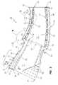
- FIG. 1is a sectional view of a portion of a gas turbine engine including a transition member according to an embodiment of the invention
- FIG. 2is an enlarged side cross sectional view of the transition member illustrated in FIG. 1 ;
- FIG. 3is a cross sectional view of a portion of a forward end of the transition member taken along line 3 - 3 in FIG. 2 ;
- FIG. 4is an enlarged cross sectional view of an area, identified as area 4 in FIG. 2 , illustrating an attachment of a first section of the transition member to a second section of the transition member;
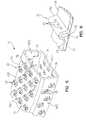
- FIG. 5is a perspective view of a portion of a casing inner wall of the second section of the transition member
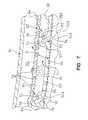
- FIG. 6is an enlarged cut-away perspective view of a spanning member associated with the casing inner wall illustrated in FIG. 5 ;
- FIG. 7is an enlarged cross sectional view of an area, identified as area 7 in FIG. 2 , illustrating a portion of the second section of the transition member.
- the engine 10includes a compressor section 12 , a combustion section 14 including a plurality of combustors 16 (only one shown), and a turbine section 18 .
- the compressor section 12inducts and pressurizes inlet air which is directed to the combustors 16 in the combustion section 14 .
- the compressed air from the compressor section 12is mixed with a fuel and ignited produce a high temperature and high velocity combustion gas flowing in a turbulent manner.
- the combustion gasthen flows to the turbine section 18 where the combustion gas is expanded to provide rotation of a turbine rotor 20 .
- a transition member 22comprising a transition duct is used to transfer the combustion gas from the combustor section 14 to the turbine section 18 .
- the transition member 22includes a forward cone shaped section defining a first section 24 and an intermediate exit piece (IEP) defining a second section 26 disposed downstream from the first section 24 .
- the first section 24comprises a forward end portion 28 forming a combustion gas inlet for receiving hot combustion gases from the combustor section 14 .
- the first section 24also includes an aft end portion 30 that is axially spaced apart from the forward end portion 28 .
- the aft end portion 30is associated with a forward end portion 32 of the second section 26 , which forward end portion 32 defines a combustion gas inlet for receiving hot combustion gases from the first section 24 .
- An aft end portion 34 of the second section 26defines a combustion gas outlet of the transition member 22 and delivers the combustion gas to the turbine section 18 .
- the forward end portion 28 of the first section 24comprises a generally circular shape and the aft end portion 30 of the first section 24 converges into a generally circular shape and corresponds with a generally circular shape of the forward end portion 32 of the second section 26 .
- the aft end portion 34 of the second section 26also comprises a generally rectangular shape, as shown in FIG. 5 .
- the first section 24comprises a wall member 36 , which includes an associated plurality of fins 38 , and an external sleeve 40 , as shown in FIG. 2 .
- the wall member 36includes a radially inner surface 42 and an opposed radially outer surface 44 .
- the radially inner surface 42defines an inner volume V 1 of the first section 24 for the flow of the combustion gas, as shown in FIG. 2 .
- the wall member 36is formed from a high heat tolerant material, such as, for example, an INCONEL alloy (INCONEL is a registered trademark of Special Metals Corporation), although any suitable high heat tolerant material may be used to form the wall member 36 .
- the wall member 24may comprise a single, unitary piece of material or may be formed from a plurality of pieces of material that are joined together using any suitable method, such as, for example, by bolting or welding.
- the wall member 36extends from the forward end portion 28 of the first section 24 to the aft end portion 30 of the first section 24 .
- the fins 38comprise generally axially extending fins 38 that extend radially outwardly from the radially outer surface 44 of the wall member 36 . As shown in FIG. 3 , the fins 38 are spaced apart to define first section cooling fluid channels 46 between adjacent fins 38 . The fins 38 extend substantially from the forward end portion 28 of the first section 24 to the aft end portion 30 of the first section 24 , although the wall member 36 extends downstream slightly further than the fins 38 , as shown in FIGS. 2 and 4 .
- the external sleeve 40is disposed about the wall member 36 and the fins 38 .
- An upstream portion 48 of the external sleeve 40is radially displaced from radially outer edges 54 of the fins 38 such that a gap 50 is formed between the fins 38 and the external sleeve 40 .
- a downstream portion 52 of the external sleeve 40abuts the radially outer edges 54 of the fins 38 .
- the external sleeve 40extends substantially from the forward end portion 28 of the first section 24 to the aft end portion 30 of the first section 24 , although the wall member 36 and the fins 38 both extend downstream slightly further than the external sleeve 40 , see also FIG. 4 .
- the upstream portion 48 of the external sleeve 40includes a plurality of apertures 56 formed therein.
- the apertures 56allow an ingress of cooling fluid to flow into the gap 50 as is described further below.
- the apertures 56are preferably spaced apart and sized to permit a desired amount of cooling fluid to flow therethrough into the gap 50 .
- the second section 26comprises an inner assembly 59 and a casing outer wall 64 disposed about the inner assembly 59 .
- the inner assembly 59includes a casing inner wall 60 and an impingement sleeve or member 62 disposed about the casing inner wall 60 and located in spaced relation to the casing outer wall 64 .
- the casing inner wall 60includes a radially inner surface 66 and an opposed radially outer surface 68 .
- the radially inner surface 66defines an inner volume V 2 of the second section 26 for the flow of the combustion gas, as shown in FIG. 2 .
- the casing inner wall 60is formed from a high heat tolerant material, such as, for example, an INCONEL alloy (INCONEL is a registered trademark of Special Metals Corporation), although any suitable high heat tolerant material may be used to form the casing inner wall 60 .
- the casing inner wall 60may comprise a single, unitary piece of material or may be formed from a plurality of pieces of material that are joined together using any suitable method, such as, for example, by bolting or welding. In the embodiment shown in FIG. 2 , the casing inner wall 60 extends from the forward end portion 32 of the second section 26 to the aft end portion 34 of the second section 26 .
- a forward end 70 of the impingement member 62is affixed to the radially outer surface 68 of the casing inner wall 60 proximate to the forward end portion 32 of the second section 26 .
- An aft end 72 of the impingement member 62is affixed to the radially outer surface 68 of the casing inner wall 60 proximate to the aft end portion 34 of the second section 26 .
- the forward and aft ends 70 , 72 of the impingement member 62may be affixed or fastened to the radially outer surface 68 by any conventional means, such as, for example, by welding.
- the impingement member 62is spaced from the radially outer surface 68 of the casing inner wall 60 such that a first IEP cooling fluid channel 74 is formed between the impingement member 62 and the radially outer surface 68 of the casing inner wall 60 .
- the impingement member 62includes a plurality of apertures 76 formed therein for permitting cooling fluid to flow therethrough into the first IEP cooling fluid channel 74 from a second IEP cooling fluid channel 78 between the impingement member 62 of the inner assembly 59 and the casing outer wall 64 (see FIGS. 4 and 7 ).
- the apertures 76are preferably spaced apart and sized to permit a desired amount of cooling fluid to flow therethrough into the first IEP cooling fluid channel 74 .
- a forward end 80 of the casing outer wall 64is affixed to the external sleeve 40 of the first section 24 at a casing interface 82 (see FIG. 4 ), such as with a plurality of casing bolts (not shown).
- An aft end 82 of the casing outer wall 64is affixed to the casing inner wall 60 proximate to the aft end portion 34 of the second section 26 .
- a plurality of spanning members 84are associated with the radially outer surface 68 of the casing inner wall 60 .
- the spanning members 84 in the illustrated embodimentcomprise radially outwardly extending portions of the casing inner wall 60 and are integrally formed with the casing inner wall 60 , such as, for example, by a stamping process.
- the spanning members 84may be formed using any suitable process and may comprise separately formed structures that are affixed to the radially outer surface 68 of the casing inner wall 60 .
- the spanning members 84are provided on radially spaced outer and inner sections 60 A and 60 B of the casing inner wall 60 , and also on first and second side sections 60 C and 60 D of the casing inner wall 60 .
- the spanning members 84may only be provided on a selected one or ones of the sections 60 A, 60 B, 60 C, 60 D.
- the spanning members 84are illustrated in the preferred embodiment as being provided on substantially the entire casing inner wall 60 , i.e., from a forward end of the casing inner wall 60 to an aft end of the casing inner wall 60 , it is contemplated that only a selected portion or portions of the casing inner wall 60 may include the spanning members 84 .
- the spanning members 84 in the embodiment showncomprise circumferentially elongate members that are arranged in circumferential rows, wherein circumferentially adjacent spanning members 84 cooperate to form each circumferential row. Further, the spanning members 84 are provided in spaced axially adjacent rows that define a circumferentially displaced, staggered pattern in the embodiment shown. Specifically, the spanning members 84 of each axially adjacent row are provided between the spanning members 84 of the fore and aft axially adjacent rows, i.e., the spanning members 84 of a middle row are provided in gaps 86 formed between the spanning members 84 defining the fore and aft axially adjacent rows. It is contemplated that the spanning members 84 could be provided in other types of arrangements according to other embodiments of the invention, such as, for example, a random pattern.
- each spanning member 84comprises a plurality of apertures 88 formed therein to allow a portion of the cooling fluid located in the first IEP cooling fluid channel 74 to flow therethrough.
- each spanning member 84comprises between 3 and 5 apertures 88 , although any suitable number of apertures 88 may be formed in the spanning members 84 .
- the apertures 88are formed only in an aft side 90 of the spanning members 84 so as to face away from a direction of flow of the cooling fluid within the first IEP cooling fluid channel 74 , which, in FIGS. 2 and 4 - 7 , flows from left to right.
- the apertures 88may be formed in forward sides 91 of the spanning members 84 instead of or in addition to the aft sides 90 of the spanning members 84 . Further, the apertures 88 may be spaced apart and sized to permit a desired amount of cooling fluid to flow therethrough.
- each of the spanning members 84comprises a circumferentially elongate slot 92 formed therein.
- the slot 92 in each of the spanning members 84is in fluid communication with the apertures 88 formed in the respective spanning member 84 , and also with a respective circumferentially elongate opening 94 or aperture formed in the radially inner surface 66 of the inner casing member 60 .
- an aft side 94 A(see FIG. 7 ) of each of the openings 94 defines a smooth transition or rounded surface between the slots 92 and the radial inner surface 66 .
- the rounded aft sides 94 Aallow cooling air to smoothly transition from the slots 92 to form a film cooling layer along the radially inner surface 66 .
- the slots 92 and their corresponding spanning members 84each include a component at an angle transverse to the radial direction, i.e., the slots 92 and spanning members 84 are each angled and include a component in the radial direction and a component in the axial direction.
- the slots 92 and their corresponding spanning members 84are formed at an angle ⁇ of about 25° to about 65° relative to the radially inner surface 66 of the inner casing member 60 , and angled into the direction of hot gas through the inner volume V 2 .
- each of the spanning members 84is displaced, i.e., axially offset, relative to the apertures 88 formed in the respective spanning member 84 such that each opening 94 , or a portion thereof, is axially displaced from direct radial alignment with its associated apertures 88 .
- an axis 88 A of each of the apertures 88is oriented transverse to an axis 92 A of the respective slot 92 and, as shown in the illustrated embodiment, is substantially perpendicular to the axis 92 A.
- the spanning members 84bridge between the casing inner wall 60 and the impingement member 62 .
- the spanning members 84 in the embodiment shownare received in circumferentially elongate pockets 96 that are formed in the impingement member 62 .
- the pockets 96 in the illustrated embodimentare individually formed to receive one or more corresponding spanning members 84 .
- the pocketsmay define continuous grooves, i.e., extending around the circumference of the impingement member 62 and thus each receiving a circumferential row of the spanning member 84 .
- a thermal barrier coating 98(hereinafter TBC), such as a thin layer of a ceramic material, may be applied on the radially inner surface 66 of the casing inner wall 60 , as shown in FIG. 7 .
- TBCthermal barrier coating
- the TBC 98is applied to provide a thermal barrier for the radially inner surface 66 of the casing inner wall 60 to assist in preventing the casing inner wall 60 from overheating.
- the sizes of the openings 94 in the radially inner surface 66 of the casing inner wall 60are preferably large enough such that the TBC 98 , when applied (and if subsequently re-applied in a re-application procedure), will not seal, i.e., close up, the openings 94 .
- the TBC 98does not substantially enter and/or clog (close off) the apertures 88 when applied/reapplied, i.e., typically in a spray-on application procedure.
- cooling fluidis introduced to the transition member 22 to cool the transition member 22 , which, if not cooled, may become overheated by the combustion gas flowing through the inner volumes V 1 , V 2 defined by the first and second sections 24 , 26 .
- the cooling fluidmay be, for example, bleed or discharge air from the compressor section 14 , which cooling fluid is located in an area outside of the external sleeve 40 , i.e. in a diffusion chamber 100 (see FIG. 1 ).
- the cooling fluidflows from the diffusion chamber 100 , through the apertures 56 formed in the external sleeve 40 of the turbine member first section 24 , and into the gap 50 formed between the external sleeve 40 and the fins 38 .
- the cooling fluidUpon contacting the fins 38 , the cooling fluid removes heat from the fins 38 and the wall member 36 via convection cooling. A pressure differential causes the cooling fluid to flow through the first section cooling fluid channels 46 between the adjacent fins 38 ( FIG. 3 ) and exit the aft end portion 30 of the first section 24 .
- a first portion of the cooling fluidfollows a first flow path P 1 (see FIG. 4 ) and a second portion of the cooling fluid follows a second flow path P 2 (see FIG. 4 ).
- the portion of the cooling fluid that follows the first flow path P 1forms a film cooling layer that flows along and provides cooling to, i.e., removes heat from, the TBC 98 and the radially inner surface 66 of the casing inner wall 60 .
- the film cooling layeris heated by the combustion gas flowing through the inner volume V 2 of the casing inner wall 60 , and also as a result of removing heat from the TBC 98 and the radially inner surface 66 of the casing inner wall 60 . As the film cooling layer is heated it is mixed with the combustion gas and is ultimately conveyed into the turbine section 18 of the engine 10 along with the combustion gas.
- the portion of the cooling fluid that follows the second flow path P 2flows into the second IEP cooling fluid channel 78 . Portions of the cooling fluid then flow through the apertures 76 formed in the impingement member 62 and into the first IEP cooling fluid channel 74 .
- the cooling fluid in the first IEP cooling fluid channel 74cools the casing inner wall 60 by removing heat from the radially outer surface 68 of the casing inner wall 60 .
- portions of the cooling fluid in the first IEP cooling fluid channel 74flow through the apertures 88 formed in the spanning members 84 and into the slots 92 of the corresponding spanning members 84 , where the cooling fluid provides additional cooling of the casing inner wall 60 by removing heat from the spanning members 84 . Thereafter, the cooling fluid flows out of the slots 92 through the openings 94 formed in the radially inner surface 66 of the casing inner wall 60 .
- the cooling fluidUpon exiting the slots 92 , the cooling fluid forms a thin film of diffusion cooling air that flows along and provides film cooling to, i.e., removes heat from, the TBC 98 and the radially inner surface 66 of the casing inner wall 60 in a manner similar to that of the portion of the cooling fluid that follows the first flow path P 1 as described above. It is noted that smooth transition defined by the aft side 94 A of each of the openings 94 is believed to provide a better film layer for film cooling of the TBC 98 and the radially inner surface 66 of the casing inner wall 60 .
- the cooling airis distributed from the slots 92 into the inner volume V 2 of the second section 26 along a rounded surface and at an angle of less than 90°, the cooling air is provided with a smooth transition to remain substantially attached to the surface of the TBC 98 as it enters the inner volume V 2 .
- the configuration of the transition member 22is believed to provide an improved distribution of cooling fluid to the first and second sections 24 , 26 and the components thereof. Specifically, the use of cooling fluid to provide convection cooling to the radially outer surface 44 of the wall member 36 of the first section 24 and the radially outer surface 68 of the casing inner wall 60 of the second section 26 , and also to provide diffusion cooling to the TBC 98 and the radially inner surface 66 of the casing inner wall member 60 via the thin film of diffusion cooling air, provides a generally balanced cooling design.
- the double metering of the portion of the cooling fluid that follows the second flow path P 2i.e., the cooling fluid which flows through the apertures 76 in the impingement member 62 and also through the apertures 88 in the spanning member 84 , provides a metered flow of the cooling fluid, as controlled by the size and arrangement of the apertures 76 , 88 .
Landscapes
- Engineering & Computer Science (AREA)
- Mechanical Engineering (AREA)
- General Engineering & Computer Science (AREA)
- Chemical & Material Sciences (AREA)
- Combustion & Propulsion (AREA)
- Turbine Rotor Nozzle Sealing (AREA)
Abstract
Description
- This application claims the benefit of U.S. Provisional Application Ser. No. 61/100,097 entitled COOLING SYSTEM FOR A TRANSITION DUCT AND RELATED METHOD, filed Sep. 25, 2008, the entire disclosure of which is incorporated by reference herein.
- The present invention relates to gas turbine engines and, more particularly, to a transition duct and a cooling thereof, wherein the transition duct conveys hot combustion gases from a combustion section of the engine to a turbine section.
- Generally, gas turbine engines have three main sections or assemblies, including a compressor assembly, a combustor assembly, and a turbine assembly. In operation, the compressor assembly compresses ambient air. The compressed air is channeled into the combustor assembly where it is mixed with a fuel and ignites, creating a working combustion gas. The combustion gas is expanded through the turbine assembly. The turbine assembly generally includes a rotating assembly comprising a centrally located rotating shaft and a plurality of rows of rotating blades attached thereto. A plurality of stationary vane assemblies, each including a plurality of stationary vanes, are connected to a casing of the turbine assembly and are located interposed between the rows of rotating blades. The expansion of the combustion gas through the rows of rotating blades and stationary vanes in the turbine assembly results in a transfer of energy from the combustion gas to the rotating assembly, causing rotation of the shaft. The shaft further supports rotating compressor blades in the compressor assembly, such that a portion of the output power from the rotation of the shaft is used to rotate the compressor blades to provide compressed air to the combustor assembly.
- A transition duct is typically used as a conduit for the passage of the combustion gas from the combustor assembly to the turbine assembly. The transition duct may be comprised, for example, of a forward cone section and an intermediate exit piece. The forward cone section may include a generally circular forward end that receives the combustion gas from a basket member of the combustor section. The forward cone section may converge into a generally circular aft end that is associated with a generally circular forward end of the intermediate exit piece. An aft end of the intermediate exit piece may include a generally rectangular shape and delivers the combustion gas to the turbine section.
- Due to the high temperature of the combustion gas that flows through the transition duct, the transition duct is typically cooled during operation of the engine to reduce the temperatures of the materials forming the forward cone section and the intermediate exit piece. Such cooling is typically required, as the materials forming the forward cone section and the intermediate exit piece, if not cooled, may become overheated, which may cause undesirable consequences, such as deterioration of the transition duct.
- Prior art solutions for cooling the transition duct include supplying a cooling fluid, such as air that is bled off from the compressor section, onto an outer surface of the transition duct to provide direct convection cooling to the transition duct. An impingement member or impingement sleeve may be provided about the outer surface of the transition duct, wherein the cooling fluid may flow through small holes formed in the impingement member before being introduced onto the outer surface of the transition duct. Other prior art solutions inject a small amount of cooling fluid along an inner surface of the transition duct. The small amount of cooling fluid acts as a cooling film to cool the inner surface of the transition duct. The cooling film is gradually heated up by the combustion gas, wherein the cooling film is mixed in with the combustion gas and is transferred into the turbine section along with the combustion gas.
- In accordance with a first aspect of the present invention, a transition member is provided between a combustion section and a turbine section in a gas turbine engine. The transition member comprises a casing inner wall, an impingement member, and a plurality of spanning members. The casing inner wall has a forward end defining a combustion gas inlet and an aft end axially spaced from the forward end and defining a combustion gas outlet. The casing inner wall includes a radially inner surface and an opposed radially outer surface. The radially inner surface defines an inner volume of the transition member therein. The impingement member is disposed radially outwardly about the casing inner wall and is spaced from the casing inner wall such that a first cooling fluid channel is formed between the impingement member and the casing inner wall. The impingement member includes a plurality of apertures formed therein for effecting a passage of cooling fluid from an area radially outward of the impingement member to the first cooling fluid channel. The spanning members extend from the radially outer surface of the casing inner wall to the impingement member. The spanning members each include a slot formed therein having a component in the radial direction. The slot is in communication with a first aperture formed in the radially inner surface of the inner wall and at least one second aperture formed in the spanning member for effecting a passage of the cooling fluid from the first cooling fluid channel to the inner volume defined within the radially inner surface of the casing inner wall.
- In accordance with a second aspect of the present invention, a transition member is provided between a combustion section and a turbine section in a gas turbine engine. The transition member comprises a casing inner wall and a plurality of circumferentially elongate spanning members. The casing inner wall has a forward end defining a combustion gas inlet and an aft end axially spaced from the forward end and defining a combustion gas outlet. The casing inner wall includes a radially inner surface and an opposed radially outer surface. The radially inner surface defines an inner volume of the transition member therein and the radially outer surface is in communication with a first cooling fluid channel containing cooling fluid. The spanning members extend radially outwardly from the radially outer surface of the casing inner wall. Each of the spanning members includes a slot formed therein. Each slot is in communication with a first aperture formed in the radially inner surface of the casing inner wall and a plurality of second apertures formed in the spanning member for effecting a passage of the cooling fluid from the first cooling fluid channel to the inner volume defined within the radially inner surface of the casing inner wall. The slots each include a component in the radial direction and a component in the axial direction such that the first aperture is not radially aligned with the second apertures.
- While the specification concludes with claims particularly pointing out and distinctly claiming the present invention, it is believed that the present invention will be better understood from the following description in conjunction with the accompanying Drawing Figures, in which like reference numerals identify like elements, and wherein:
FIG. 1 is a sectional view of a portion of a gas turbine engine including a transition member according to an embodiment of the invention;FIG. 2 is an enlarged side cross sectional view of the transition member illustrated inFIG. 1 ;FIG. 3 is a cross sectional view of a portion of a forward end of the transition member taken along line3-3 inFIG. 2 ;FIG. 4 is an enlarged cross sectional view of an area, identified asarea 4 inFIG. 2 , illustrating an attachment of a first section of the transition member to a second section of the transition member;FIG. 5 is a perspective view of a portion of a casing inner wall of the second section of the transition member;FIG. 6 is an enlarged cut-away perspective view of a spanning member associated with the casing inner wall illustrated inFIG. 5 ; andFIG. 7 is an enlarged cross sectional view of an area, identified asarea 7 inFIG. 2 , illustrating a portion of the second section of the transition member.- In the following detailed description of the preferred embodiment, reference is made to the accompanying drawings that form a part hereof, and in which is shown by way of illustration, and not by way of limitation, a specific preferred embodiment in which the invention may be practiced. It is to be understood that other embodiments may be utilized and that changes may be made without departing from the spirit and scope of the present invention.
- Referring to
FIG. 1 , a portion of agas turbine engine 10 is shown. Theengine 10 includes a compressor section12, acombustion section 14 including a plurality of combustors16 (only one shown), and aturbine section 18. The compressor section12 inducts and pressurizes inlet air which is directed to thecombustors 16 in thecombustion section 14. Upon entering thecombustors 16, the compressed air from the compressor section12 is mixed with a fuel and ignited produce a high temperature and high velocity combustion gas flowing in a turbulent manner. The combustion gas then flows to theturbine section 18 where the combustion gas is expanded to provide rotation of aturbine rotor 20. Atransition member 22 comprising a transition duct is used to transfer the combustion gas from thecombustor section 14 to theturbine section 18. - Referring to
FIG. 2 , thetransition member 22 includes a forward cone shaped section defining afirst section 24 and an intermediate exit piece (IEP) defining asecond section 26 disposed downstream from thefirst section 24. Thefirst section 24 comprises aforward end portion 28 forming a combustion gas inlet for receiving hot combustion gases from thecombustor section 14. Thefirst section 24 also includes anaft end portion 30 that is axially spaced apart from theforward end portion 28. Theaft end portion 30 is associated with aforward end portion 32 of thesecond section 26, whichforward end portion 32 defines a combustion gas inlet for receiving hot combustion gases from thefirst section 24. Anaft end portion 34 of thesecond section 26 defines a combustion gas outlet of thetransition member 22 and delivers the combustion gas to theturbine section 18. In the embodiment shown, theforward end portion 28 of thefirst section 24 comprises a generally circular shape and theaft end portion 30 of thefirst section 24 converges into a generally circular shape and corresponds with a generally circular shape of theforward end portion 32 of thesecond section 26. Theaft end portion 34 of thesecond section 26 also comprises a generally rectangular shape, as shown inFIG. 5 . - The
first section 24 comprises awall member 36, which includes an associated plurality offins 38, and anexternal sleeve 40, as shown inFIG. 2 . Thewall member 36 includes a radiallyinner surface 42 and an opposed radiallyouter surface 44. The radiallyinner surface 42 defines an inner volume V1of thefirst section 24 for the flow of the combustion gas, as shown inFIG. 2 . Thewall member 36 is formed from a high heat tolerant material, such as, for example, an INCONEL alloy (INCONEL is a registered trademark of Special Metals Corporation), although any suitable high heat tolerant material may be used to form thewall member 36. Thewall member 24 may comprise a single, unitary piece of material or may be formed from a plurality of pieces of material that are joined together using any suitable method, such as, for example, by bolting or welding. In the embodiment shown inFIG. 2 , thewall member 36 extends from theforward end portion 28 of thefirst section 24 to theaft end portion 30 of thefirst section 24. - The
fins 38 comprise generally axially extendingfins 38 that extend radially outwardly from the radiallyouter surface 44 of thewall member 36. As shown inFIG. 3 , thefins 38 are spaced apart to define first section coolingfluid channels 46 betweenadjacent fins 38. Thefins 38 extend substantially from theforward end portion 28 of thefirst section 24 to theaft end portion 30 of thefirst section 24, although thewall member 36 extends downstream slightly further than thefins 38, as shown inFIGS. 2 and 4 . - Referring to
FIG. 2 , theexternal sleeve 40 is disposed about thewall member 36 and thefins 38. Anupstream portion 48 of theexternal sleeve 40 is radially displaced from radiallyouter edges 54 of thefins 38 such that agap 50 is formed between thefins 38 and theexternal sleeve 40. Adownstream portion 52 of theexternal sleeve 40 abuts the radiallyouter edges 54 of thefins 38. Theexternal sleeve 40 extends substantially from theforward end portion 28 of thefirst section 24 to theaft end portion 30 of thefirst section 24, although thewall member 36 and thefins 38 both extend downstream slightly further than theexternal sleeve 40, see alsoFIG. 4 . - Referring to
FIGS. 2 and 3 , theupstream portion 48 of theexternal sleeve 40 includes a plurality ofapertures 56 formed therein. Theapertures 56 allow an ingress of cooling fluid to flow into thegap 50 as is described further below. Theapertures 56 are preferably spaced apart and sized to permit a desired amount of cooling fluid to flow therethrough into thegap 50. - Referring to
FIG. 2 , thesecond section 26 comprises aninner assembly 59 and a casingouter wall 64 disposed about theinner assembly 59. Theinner assembly 59 includes a casinginner wall 60 and an impingement sleeve ormember 62 disposed about the casinginner wall 60 and located in spaced relation to the casingouter wall 64. Referring additionally toFIG. 4 , the casinginner wall 60 includes a radiallyinner surface 66 and an opposed radiallyouter surface 68. The radiallyinner surface 66 defines an inner volume V2of thesecond section 26 for the flow of the combustion gas, as shown inFIG. 2 . The casinginner wall 60 is formed from a high heat tolerant material, such as, for example, an INCONEL alloy (INCONEL is a registered trademark of Special Metals Corporation), although any suitable high heat tolerant material may be used to form the casinginner wall 60. The casinginner wall 60 may comprise a single, unitary piece of material or may be formed from a plurality of pieces of material that are joined together using any suitable method, such as, for example, by bolting or welding. In the embodiment shown inFIG. 2 , the casinginner wall 60 extends from theforward end portion 32 of thesecond section 26 to theaft end portion 34 of thesecond section 26. - Referring to
FIGS. 2 and 4 , aforward end 70 of theimpingement member 62 is affixed to the radiallyouter surface 68 of the casinginner wall 60 proximate to theforward end portion 32 of thesecond section 26. Anaft end 72 of theimpingement member 62 is affixed to the radiallyouter surface 68 of the casinginner wall 60 proximate to theaft end portion 34 of thesecond section 26. The forward and aft ends70,72 of theimpingement member 62 may be affixed or fastened to the radiallyouter surface 68 by any conventional means, such as, for example, by welding. - Referring to
FIGS. 2 ,4, and7, theimpingement member 62 is spaced from the radiallyouter surface 68 of the casinginner wall 60 such that a first IEP coolingfluid channel 74 is formed between theimpingement member 62 and the radiallyouter surface 68 of the casinginner wall 60. Theimpingement member 62 includes a plurality ofapertures 76 formed therein for permitting cooling fluid to flow therethrough into the first IEP coolingfluid channel 74 from a second IEP coolingfluid channel 78 between theimpingement member 62 of theinner assembly 59 and the casing outer wall64 (seeFIGS. 4 and 7 ). Theapertures 76 are preferably spaced apart and sized to permit a desired amount of cooling fluid to flow therethrough into the first IEP coolingfluid channel 74. - Referring to
FIG. 2 , aforward end 80 of the casingouter wall 64 is affixed to theexternal sleeve 40 of thefirst section 24 at a casing interface82 (seeFIG. 4 ), such as with a plurality of casing bolts (not shown). Anaft end 82 of the casingouter wall 64 is affixed to the casinginner wall 60 proximate to theaft end portion 34 of thesecond section 26. - Referring now to
FIG. 5 , a plurality of spanningmembers 84 are associated with the radiallyouter surface 68 of the casinginner wall 60. The spanningmembers 84 in the illustrated embodiment comprise radially outwardly extending portions of the casinginner wall 60 and are integrally formed with the casinginner wall 60, such as, for example, by a stamping process. However, the spanningmembers 84 may be formed using any suitable process and may comprise separately formed structures that are affixed to the radiallyouter surface 68 of the casinginner wall 60. - In the embodiment shown in
FIG. 5 , the spanningmembers 84 are provided on radially spaced outer andinner sections inner wall 60, and also on first andsecond side sections inner wall 60. However, the spanningmembers 84 may only be provided on a selected one or ones of thesections members 84 are illustrated in the preferred embodiment as being provided on substantially the entire casinginner wall 60, i.e., from a forward end of the casinginner wall 60 to an aft end of the casinginner wall 60, it is contemplated that only a selected portion or portions of the casinginner wall 60 may include the spanningmembers 84. - The spanning
members 84 in the embodiment shown comprise circumferentially elongate members that are arranged in circumferential rows, wherein circumferentially adjacent spanningmembers 84 cooperate to form each circumferential row. Further, the spanningmembers 84 are provided in spaced axially adjacent rows that define a circumferentially displaced, staggered pattern in the embodiment shown. Specifically, the spanningmembers 84 of each axially adjacent row are provided between the spanningmembers 84 of the fore and aft axially adjacent rows, i.e., the spanningmembers 84 of a middle row are provided ingaps 86 formed between the spanningmembers 84 defining the fore and aft axially adjacent rows. It is contemplated that the spanningmembers 84 could be provided in other types of arrangements according to other embodiments of the invention, such as, for example, a random pattern. - Referring to
FIG. 6 , each spanningmember 84 comprises a plurality ofapertures 88 formed therein to allow a portion of the cooling fluid located in the first IEP coolingfluid channel 74 to flow therethrough. Preferably, each spanningmember 84 comprises between3 and5apertures 88, although any suitable number ofapertures 88 may be formed in the spanningmembers 84. In the embodiment shown, theapertures 88 are formed only in anaft side 90 of the spanningmembers 84 so as to face away from a direction of flow of the cooling fluid within the first IEP coolingfluid channel 74, which, in FIGS.2 and4-7, flows from left to right. However, theapertures 88 may be formed in forward sides91 of the spanningmembers 84 instead of or in addition to theaft sides 90 of the spanningmembers 84. Further, theapertures 88 may be spaced apart and sized to permit a desired amount of cooling fluid to flow therethrough. - Referring now to
FIG. 7 , each of the spanningmembers 84 comprises a circumferentiallyelongate slot 92 formed therein. Theslot 92 in each of the spanningmembers 84 is in fluid communication with theapertures 88 formed in the respective spanningmember 84, and also with a respective circumferentiallyelongate opening 94 or aperture formed in the radiallyinner surface 66 of theinner casing member 60. It is noted that anaft side 94A (seeFIG. 7 ) of each of theopenings 94 defines a smooth transition or rounded surface between theslots 92 and the radialinner surface 66. The roundedaft sides 94A allow cooling air to smoothly transition from theslots 92 to form a film cooling layer along the radiallyinner surface 66. - As shown in
FIG. 7 , theslots 92 and their corresponding spanningmembers 84 each include a component at an angle transverse to the radial direction, i.e., theslots 92 and spanningmembers 84 are each angled and include a component in the radial direction and a component in the axial direction. In a preferred embodiment, theslots 92 and their corresponding spanningmembers 84 are formed at an angle θ of about 25° to about 65° relative to the radiallyinner surface 66 of theinner casing member 60, and angled into the direction of hot gas through the inner volume V2. - Further, the
opening 94 of each of the spanningmembers 84 is displaced, i.e., axially offset, relative to theapertures 88 formed in the respective spanningmember 84 such that eachopening 94, or a portion thereof, is axially displaced from direct radial alignment with its associatedapertures 88. Further, anaxis 88A of each of theapertures 88 is oriented transverse to anaxis 92A of therespective slot 92 and, as shown in the illustrated embodiment, is substantially perpendicular to theaxis 92A. - As shown in
FIGS. 4 and 7 , the spanningmembers 84 bridge between the casinginner wall 60 and theimpingement member 62. The spanningmembers 84 in the embodiment shown are received in circumferentiallyelongate pockets 96 that are formed in theimpingement member 62. Thepockets 96 in the illustrated embodiment are individually formed to receive one or more corresponding spanningmembers 84. However, the pockets may define continuous grooves, i.e., extending around the circumference of theimpingement member 62 and thus each receiving a circumferential row of the spanningmember 84. - Optionally, a thermal barrier coating98 (hereinafter TBC), such as a thin layer of a ceramic material, may be applied on the radially
inner surface 66 of the casinginner wall 60, as shown inFIG. 7 . TheTBC 98 is applied to provide a thermal barrier for the radiallyinner surface 66 of the casinginner wall 60 to assist in preventing the casinginner wall 60 from overheating. It is noted that the sizes of theopenings 94 in the radiallyinner surface 66 of the casinginner wall 60 are preferably large enough such that theTBC 98, when applied (and if subsequently re-applied in a re-application procedure), will not seal, i.e., close up, theopenings 94. It is also noted that since theapertures 88 formed in each of the spanningmembers 84 are axially offset from therespective opening 94 of each spanningmember 84, theTBC 98 does not substantially enter and/or clog (close off) theapertures 88 when applied/reapplied, i.e., typically in a spray-on application procedure. - During operation of the
engine 10, cooling fluid is introduced to thetransition member 22 to cool thetransition member 22, which, if not cooled, may become overheated by the combustion gas flowing through the inner volumes V1, V2defined by the first andsecond sections compressor section 14, which cooling fluid is located in an area outside of theexternal sleeve 40, i.e. in a diffusion chamber100 (seeFIG. 1 ). The cooling fluid flows from thediffusion chamber 100, through theapertures 56 formed in theexternal sleeve 40 of the turbine memberfirst section 24, and into thegap 50 formed between theexternal sleeve 40 and thefins 38. Upon contacting thefins 38, the cooling fluid removes heat from thefins 38 and thewall member 36 via convection cooling. A pressure differential causes the cooling fluid to flow through the first section coolingfluid channels 46 between the adjacent fins38 (FIG. 3 ) and exit theaft end portion 30 of thefirst section 24. - Upon exiting the
first section 24 of thetransition member 22 and reaching theforward end portion 32 of thesecond section 26, a first portion of the cooling fluid follows a first flow path P1(seeFIG. 4 ) and a second portion of the cooling fluid follows a second flow path P2(seeFIG. 4 ). The portion of the cooling fluid that follows the first flow path P1forms a film cooling layer that flows along and provides cooling to, i.e., removes heat from, theTBC 98 and the radiallyinner surface 66 of the casinginner wall 60. It is noted that the film cooling layer is heated by the combustion gas flowing through the inner volume V2of the casinginner wall 60, and also as a result of removing heat from theTBC 98 and the radiallyinner surface 66 of the casinginner wall 60. As the film cooling layer is heated it is mixed with the combustion gas and is ultimately conveyed into theturbine section 18 of theengine 10 along with the combustion gas. - The portion of the cooling fluid that follows the second flow path P2flows into the second IEP cooling
fluid channel 78. Portions of the cooling fluid then flow through theapertures 76 formed in theimpingement member 62 and into the first IEP coolingfluid channel 74. The cooling fluid in the first IEP coolingfluid channel 74 cools the casinginner wall 60 by removing heat from the radiallyouter surface 68 of the casinginner wall 60. - Referring to
FIGS. 2 ,4, and7, portions of the cooling fluid in the first IEP coolingfluid channel 74 flow through theapertures 88 formed in the spanningmembers 84 and into theslots 92 of the corresponding spanningmembers 84, where the cooling fluid provides additional cooling of the casinginner wall 60 by removing heat from the spanningmembers 84. Thereafter, the cooling fluid flows out of theslots 92 through theopenings 94 formed in the radiallyinner surface 66 of the casinginner wall 60. - Upon exiting the
slots 92, the cooling fluid forms a thin film of diffusion cooling air that flows along and provides film cooling to, i.e., removes heat from, theTBC 98 and the radiallyinner surface 66 of the casinginner wall 60 in a manner similar to that of the portion of the cooling fluid that follows the first flow path P1as described above. It is noted that smooth transition defined by theaft side 94A of each of theopenings 94 is believed to provide a better film layer for film cooling of theTBC 98 and the radiallyinner surface 66 of the casinginner wall 60. Specifically, since the cooling air is distributed from theslots 92 into the inner volume V2of thesecond section 26 along a rounded surface and at an angle of less than 90°, the cooling air is provided with a smooth transition to remain substantially attached to the surface of theTBC 98 as it enters the inner volume V2. - The configuration of the
transition member 22 is believed to provide an improved distribution of cooling fluid to the first andsecond sections outer surface 44 of thewall member 36 of thefirst section 24 and the radiallyouter surface 68 of the casinginner wall 60 of thesecond section 26, and also to provide diffusion cooling to theTBC 98 and the radiallyinner surface 66 of the casinginner wall member 60 via the thin film of diffusion cooling air, provides a generally balanced cooling design. Further, the double metering of the portion of the cooling fluid that follows the second flow path P2, i.e., the cooling fluid which flows through theapertures 76 in theimpingement member 62 and also through theapertures 88 in the spanningmember 84, provides a metered flow of the cooling fluid, as controlled by the size and arrangement of theapertures - While particular embodiments of the present invention have been illustrated and described, it would be obvious to those skilled in the art that various other changes and modifications can be made without departing from the spirit and scope of the invention. It is therefore intended to cover in the appended claims all such changes and modifications that are within the scope of this invention.
Claims (19)
Priority Applications (1)
| Application Number | Priority Date | Filing Date | Title |
|---|---|---|---|
| US12/338,401US8033119B2 (en) | 2008-09-25 | 2008-12-18 | Gas turbine transition duct |
Applications Claiming Priority (2)
| Application Number | Priority Date | Filing Date | Title |
|---|---|---|---|
| US10009708P | 2008-09-25 | 2008-09-25 | |
| US12/338,401US8033119B2 (en) | 2008-09-25 | 2008-12-18 | Gas turbine transition duct |
Publications (2)
| Publication Number | Publication Date |
|---|---|
| US20100071382A1true US20100071382A1 (en) | 2010-03-25 |
| US8033119B2 US8033119B2 (en) | 2011-10-11 |
Family
ID=42036232
Family Applications (1)
| Application Number | Title | Priority Date | Filing Date |
|---|---|---|---|
| US12/338,401Expired - Fee RelatedUS8033119B2 (en) | 2008-09-25 | 2008-12-18 | Gas turbine transition duct |
Country Status (1)
| Country | Link |
|---|---|
| US (1) | US8033119B2 (en) |
Cited By (36)
| Publication number | Priority date | Publication date | Assignee | Title |
|---|---|---|---|---|
| US20090077977A1 (en)* | 2007-09-26 | 2009-03-26 | Snecma | Combustion chamber of a turbomachine |
| US20100170256A1 (en)* | 2009-01-06 | 2010-07-08 | General Electric Company | Ring cooling for a combustion liner and related method |
| WO2011156078A1 (en)* | 2010-06-11 | 2011-12-15 | Siemens Energy, Inc. | Cooled conduit for conveying combustion gases in a gas turbine engine |
| US20120079828A1 (en)* | 2010-10-05 | 2012-04-05 | Hitachi, Ltd. | Gas Turbine Combustor |
| US20120121408A1 (en)* | 2010-11-15 | 2012-05-17 | Ching-Pang Lee | Turbine transition component formed from a two section, air-cooled multi-layer outer panel for use in a gas turbine engine |
| US20120121381A1 (en)* | 2010-11-15 | 2012-05-17 | Charron Richard C | Turbine transition component formed from an air-cooled multi-layer outer panel for use in a gas turbine engine |
| CN102628596A (en)* | 2011-02-03 | 2012-08-08 | 通用电气公司 | Method and apparatus for cooling combustor liner in combustor |
| US20120247125A1 (en)* | 2009-12-07 | 2012-10-04 | Mitsubishi Heavy Industries, Ltd. | Communicating structure between combustor and turbine portion and gas turbine |
| US20120275900A1 (en)* | 2011-04-27 | 2012-11-01 | Snider Raymond G | Method of forming a multi-panel outer wall of a component for use in a gas turbine engine |
| EP2618056A1 (en)* | 2012-01-18 | 2013-07-24 | General Electric Company | Combustor assembly with impingement sleeve holes and turbulators |
| US20130219921A1 (en)* | 2012-02-29 | 2013-08-29 | David J. Wiebe | Mid-section of a can-annular gas turbine engine with a cooling system for the transition |
| US20130318986A1 (en)* | 2012-06-05 | 2013-12-05 | General Electric Company | Impingement cooled combustor |
| US20130330167A1 (en)* | 2012-06-08 | 2013-12-12 | Philip Robert Rioux | Active clearance control for gas turbine engine |
| US20140010644A1 (en)* | 2012-07-05 | 2014-01-09 | Richard C. Charron | Combustor transition duct assembly with inner liner |
| WO2014018385A1 (en)* | 2012-07-26 | 2014-01-30 | United Technologies Corporation | Gas turbine engine exhaust duct |
| US20140033726A1 (en)* | 2012-08-06 | 2014-02-06 | Wei Chen | Liner cooling assembly for a gas turbine system |
| US8647053B2 (en) | 2010-08-09 | 2014-02-11 | Siemens Energy, Inc. | Cooling arrangement for a turbine component |
| US8667682B2 (en) | 2011-04-27 | 2014-03-11 | Siemens Energy, Inc. | Method of fabricating a nearwall nozzle impingement cooled component for an internal combustion engine |
| US20140230441A1 (en)* | 2013-02-15 | 2014-08-21 | Clinton A. Mayer | Heat shield manifold system for a midframe case of a gas turbine engine |
| US20140338304A1 (en)* | 2012-07-05 | 2014-11-20 | Reinhard Schilp | Air regulation for film cooling and emission control of combustion gas structure |
| WO2014149119A3 (en)* | 2013-03-15 | 2014-11-27 | Rolls-Royce Corporation | Gas turbine engine combustor liner |
| JP2015010526A (en)* | 2013-06-28 | 2015-01-19 | 三菱日立パワーシステムズ株式会社 | Gas turbine combustor |
| US20150082794A1 (en)* | 2013-09-26 | 2015-03-26 | Reinhard Schilp | Apparatus for acoustic damping and operational control of damping, cooling, and emissions in a gas turbine engine |
| US9091170B2 (en) | 2008-12-24 | 2015-07-28 | Mitsubishi Hitachi Power Systems, Ltd. | One-stage stator vane cooling structure and gas turbine |
| US20150369077A1 (en)* | 2013-02-08 | 2015-12-24 | General Electric Company | Suction-based active clearance control system |
| US20160370008A1 (en)* | 2013-06-14 | 2016-12-22 | United Technologies Corporation | Conductive panel surface cooling augmentation for gas turbine engine combustor |
| CN106795773A (en)* | 2014-10-07 | 2017-05-31 | 西门子能源公司 | For the arrangement of gas turbine combustion engine |
| US20170167729A1 (en)* | 2014-07-30 | 2017-06-15 | Siemens Aktiengesellschaft | Multiple feed platefins within a hot gas path cooling system in a combustor basket in a combustion turbine engine |
| US20190017440A1 (en)* | 2017-07-17 | 2019-01-17 | United Technologies Corporation | Combustor panel standoffs with cooling holes |
| CN109667668A (en)* | 2017-10-13 | 2019-04-23 | 通用电气公司 | Afterframe component for gas turbine transition piece |
| US10386067B2 (en)* | 2016-09-15 | 2019-08-20 | United Technologies Corporation | Wall panel assembly for a gas turbine engine |
| US20190301375A1 (en)* | 2018-03-28 | 2019-10-03 | Doosan Heavy Industries & Construction Co., Ltd. | Combustor with flow guide in double pipe type liner, and gas turbine having same |
| US20200173294A1 (en)* | 2018-11-29 | 2020-06-04 | Doosan Heavy Industries & Construction Co., Ltd. | Fin-pin flow guide for efficient transition piece cooling |
| US10775044B2 (en)* | 2018-10-26 | 2020-09-15 | Honeywell International Inc. | Gas turbine engine dual-wall hot section structure |
| US11149949B2 (en) | 2016-07-25 | 2021-10-19 | Siemens Energy Global GmbH & Co. KG | Converging duct with elongated and hexagonal cooling features |
| US11242990B2 (en)* | 2019-04-10 | 2022-02-08 | Doosan Heavy Industries & Construction Co., Ltd. | Liner cooling structure with reduced pressure losses and gas turbine combustor having same |
Families Citing this family (11)
| Publication number | Priority date | Publication date | Assignee | Title |
|---|---|---|---|---|
| US8549861B2 (en)* | 2009-01-07 | 2013-10-08 | General Electric Company | Method and apparatus to enhance transition duct cooling in a gas turbine engine |
| US8695322B2 (en)* | 2009-03-30 | 2014-04-15 | General Electric Company | Thermally decoupled can-annular transition piece |
| US8448416B2 (en)* | 2009-03-30 | 2013-05-28 | General Electric Company | Combustor liner |
| US8857501B2 (en)* | 2010-11-24 | 2014-10-14 | Honeywell International Inc. | Entrainment heat sink devices |
| US9085981B2 (en)* | 2012-10-19 | 2015-07-21 | Siemens Energy, Inc. | Ducting arrangement for cooling a gas turbine structure |
| US9366438B2 (en)* | 2013-02-14 | 2016-06-14 | Siemens Aktiengesellschaft | Flow sleeve inlet assembly in a gas turbine engine |
| US10100737B2 (en) | 2013-05-16 | 2018-10-16 | Siemens Energy, Inc. | Impingement cooling arrangement having a snap-in plate |
| US20160238249A1 (en)* | 2013-10-18 | 2016-08-18 | United Technologies Corporation | Combustor wall having cooling element(s) within a cooling cavity |
| US9453424B2 (en)* | 2013-10-21 | 2016-09-27 | Siemens Energy, Inc. | Reverse bulk flow effusion cooling |
| US20160348911A1 (en)* | 2013-12-12 | 2016-12-01 | Siemens Energy, Inc. | W501 d5/d5a df42 combustion system |
| KR101556532B1 (en)* | 2014-01-16 | 2015-10-01 | 두산중공업 주식회사 | liner, flow sleeve and gas turbine combustor including cooling sleeve |
Citations (21)
| Publication number | Priority date | Publication date | Assignee | Title |
|---|---|---|---|---|
| US3652181A (en)* | 1970-11-23 | 1972-03-28 | Carl F Wilhelm Jr | Cooling sleeve for gas turbine combustor transition member |
| US3793827A (en)* | 1972-11-02 | 1974-02-26 | Gen Electric | Stiffener for combustor liner |
| US4526226A (en)* | 1981-08-31 | 1985-07-02 | General Electric Company | Multiple-impingement cooled structure |
| US4719748A (en)* | 1985-05-14 | 1988-01-19 | General Electric Company | Impingement cooled transition duct |
| US4790140A (en)* | 1985-01-18 | 1988-12-13 | Ishikawajima-Harima Jukogyo Kabushiki Kaisha | Liner cooling construction for gas turbine combustor or the like |
| US4903477A (en)* | 1987-04-01 | 1990-02-27 | Westinghouse Electric Corp. | Gas turbine combustor transition duct forced convection cooling |
| US5237813A (en)* | 1992-08-21 | 1993-08-24 | Allied-Signal Inc. | Annular combustor with outer transition liner cooling |
| US5528904A (en)* | 1994-02-28 | 1996-06-25 | Jones; Charles R. | Coated hot gas duct liner |
| US6018950A (en)* | 1997-06-13 | 2000-02-01 | Siemens Westinghouse Power Corporation | Combustion turbine modular cooling panel |
| US6282905B1 (en)* | 1998-11-12 | 2001-09-04 | Mitsubishi Heavy Industries, Ltd. | Gas turbine combustor cooling structure |
| US6412268B1 (en)* | 2000-04-06 | 2002-07-02 | General Electric Company | Cooling air recycling for gas turbine transition duct end frame and related method |
| US6553766B2 (en)* | 2000-04-13 | 2003-04-29 | Mitsubishi Heavy Industries, Ltd. | Cooling structure of a combustor tail tube |
| US6568187B1 (en)* | 2001-12-10 | 2003-05-27 | Power Systems Mfg, Llc | Effusion cooled transition duct |
| US6640547B2 (en)* | 2001-12-10 | 2003-11-04 | Power Systems Mfg, Llc | Effusion cooled transition duct with shaped cooling holes |
| US7010921B2 (en)* | 2004-06-01 | 2006-03-14 | General Electric Company | Method and apparatus for cooling combustor liner and transition piece of a gas turbine |
| US7137241B2 (en)* | 2004-04-30 | 2006-11-21 | Power Systems Mfg, Llc | Transition duct apparatus having reduced pressure loss |
| US20070175220A1 (en)* | 2006-02-02 | 2007-08-02 | Siemens Power Generation, Inc. | Gas turbine engine curved diffuser with partial impingement cooling apparatus for transitions |
| US7278254B2 (en)* | 2005-01-27 | 2007-10-09 | Siemens Power Generation, Inc. | Cooling system for a transition bracket of a transition in a turbine engine |
| US7310938B2 (en)* | 2004-12-16 | 2007-12-25 | Siemens Power Generation, Inc. | Cooled gas turbine transition duct |
| US7340881B2 (en)* | 2002-12-12 | 2008-03-11 | Hitachi, Ltd. | Gas turbine combustor |
| US7827801B2 (en)* | 2006-02-09 | 2010-11-09 | Siemens Energy, Inc. | Gas turbine engine transitions comprising closed cooled transition cooling channels |
- 2008
- 2008-12-18USUS12/338,401patent/US8033119B2/ennot_activeExpired - Fee Related
Patent Citations (21)
| Publication number | Priority date | Publication date | Assignee | Title |
|---|---|---|---|---|
| US3652181A (en)* | 1970-11-23 | 1972-03-28 | Carl F Wilhelm Jr | Cooling sleeve for gas turbine combustor transition member |
| US3793827A (en)* | 1972-11-02 | 1974-02-26 | Gen Electric | Stiffener for combustor liner |
| US4526226A (en)* | 1981-08-31 | 1985-07-02 | General Electric Company | Multiple-impingement cooled structure |
| US4790140A (en)* | 1985-01-18 | 1988-12-13 | Ishikawajima-Harima Jukogyo Kabushiki Kaisha | Liner cooling construction for gas turbine combustor or the like |
| US4719748A (en)* | 1985-05-14 | 1988-01-19 | General Electric Company | Impingement cooled transition duct |
| US4903477A (en)* | 1987-04-01 | 1990-02-27 | Westinghouse Electric Corp. | Gas turbine combustor transition duct forced convection cooling |
| US5237813A (en)* | 1992-08-21 | 1993-08-24 | Allied-Signal Inc. | Annular combustor with outer transition liner cooling |
| US5528904A (en)* | 1994-02-28 | 1996-06-25 | Jones; Charles R. | Coated hot gas duct liner |
| US6018950A (en)* | 1997-06-13 | 2000-02-01 | Siemens Westinghouse Power Corporation | Combustion turbine modular cooling panel |
| US6282905B1 (en)* | 1998-11-12 | 2001-09-04 | Mitsubishi Heavy Industries, Ltd. | Gas turbine combustor cooling structure |
| US6412268B1 (en)* | 2000-04-06 | 2002-07-02 | General Electric Company | Cooling air recycling for gas turbine transition duct end frame and related method |
| US6553766B2 (en)* | 2000-04-13 | 2003-04-29 | Mitsubishi Heavy Industries, Ltd. | Cooling structure of a combustor tail tube |
| US6568187B1 (en)* | 2001-12-10 | 2003-05-27 | Power Systems Mfg, Llc | Effusion cooled transition duct |
| US6640547B2 (en)* | 2001-12-10 | 2003-11-04 | Power Systems Mfg, Llc | Effusion cooled transition duct with shaped cooling holes |
| US7340881B2 (en)* | 2002-12-12 | 2008-03-11 | Hitachi, Ltd. | Gas turbine combustor |
| US7137241B2 (en)* | 2004-04-30 | 2006-11-21 | Power Systems Mfg, Llc | Transition duct apparatus having reduced pressure loss |
| US7010921B2 (en)* | 2004-06-01 | 2006-03-14 | General Electric Company | Method and apparatus for cooling combustor liner and transition piece of a gas turbine |
| US7310938B2 (en)* | 2004-12-16 | 2007-12-25 | Siemens Power Generation, Inc. | Cooled gas turbine transition duct |
| US7278254B2 (en)* | 2005-01-27 | 2007-10-09 | Siemens Power Generation, Inc. | Cooling system for a transition bracket of a transition in a turbine engine |
| US20070175220A1 (en)* | 2006-02-02 | 2007-08-02 | Siemens Power Generation, Inc. | Gas turbine engine curved diffuser with partial impingement cooling apparatus for transitions |
| US7827801B2 (en)* | 2006-02-09 | 2010-11-09 | Siemens Energy, Inc. | Gas turbine engine transitions comprising closed cooled transition cooling channels |
Cited By (59)
| Publication number | Priority date | Publication date | Assignee | Title |
|---|---|---|---|---|
| US20090077977A1 (en)* | 2007-09-26 | 2009-03-26 | Snecma | Combustion chamber of a turbomachine |
| US8291709B2 (en)* | 2007-09-26 | 2012-10-23 | Snecma | Combustion chamber of a turbomachine including cooling grooves |
| US9091170B2 (en) | 2008-12-24 | 2015-07-28 | Mitsubishi Hitachi Power Systems, Ltd. | One-stage stator vane cooling structure and gas turbine |
| US20100170256A1 (en)* | 2009-01-06 | 2010-07-08 | General Electric Company | Ring cooling for a combustion liner and related method |
| US8677759B2 (en)* | 2009-01-06 | 2014-03-25 | General Electric Company | Ring cooling for a combustion liner and related method |
| US9395085B2 (en)* | 2009-12-07 | 2016-07-19 | Mitsubishi Hitachi Power Systems, Ltd. | Communicating structure between adjacent combustors and turbine portion and gas turbine |
| US20120247125A1 (en)* | 2009-12-07 | 2012-10-04 | Mitsubishi Heavy Industries, Ltd. | Communicating structure between combustor and turbine portion and gas turbine |
| WO2011156078A1 (en)* | 2010-06-11 | 2011-12-15 | Siemens Energy, Inc. | Cooled conduit for conveying combustion gases in a gas turbine engine |
| US9810081B2 (en) | 2010-06-11 | 2017-11-07 | Siemens Energy, Inc. | Cooled conduit for conveying combustion gases |
| US8647053B2 (en) | 2010-08-09 | 2014-02-11 | Siemens Energy, Inc. | Cooling arrangement for a turbine component |
| US20120079828A1 (en)* | 2010-10-05 | 2012-04-05 | Hitachi, Ltd. | Gas Turbine Combustor |
| US8955332B2 (en) | 2010-10-05 | 2015-02-17 | Mitsubishi Hitachi Power Systems, Ltd. | Gas turbine combustor including a transition piece flow sleeve wrapped on an outside surface of a transition piece |
| US8839626B2 (en)* | 2010-10-05 | 2014-09-23 | Hitachi, Ltd. | Gas turbine combustor including a transition piece flow sleeve wrapped on an outside surface of a transition piece |
| US20120121408A1 (en)* | 2010-11-15 | 2012-05-17 | Ching-Pang Lee | Turbine transition component formed from a two section, air-cooled multi-layer outer panel for use in a gas turbine engine |
| US9133721B2 (en)* | 2010-11-15 | 2015-09-15 | Siemens Energy, Inc. | Turbine transition component formed from a two section, air-cooled multi-layer outer panel for use in a gas turbine engine |
| US9097117B2 (en)* | 2010-11-15 | 2015-08-04 | Siemens Energy, Inc | Turbine transition component formed from an air-cooled multi-layer outer panel for use in a gas turbine engine |
| US20120121381A1 (en)* | 2010-11-15 | 2012-05-17 | Charron Richard C | Turbine transition component formed from an air-cooled multi-layer outer panel for use in a gas turbine engine |
| CN102628596A (en)* | 2011-02-03 | 2012-08-08 | 通用电气公司 | Method and apparatus for cooling combustor liner in combustor |
| US8667682B2 (en) | 2011-04-27 | 2014-03-11 | Siemens Energy, Inc. | Method of fabricating a nearwall nozzle impingement cooled component for an internal combustion engine |
| US8727714B2 (en)* | 2011-04-27 | 2014-05-20 | Siemens Energy, Inc. | Method of forming a multi-panel outer wall of a component for use in a gas turbine engine |
| US20120275900A1 (en)* | 2011-04-27 | 2012-11-01 | Snider Raymond G | Method of forming a multi-panel outer wall of a component for use in a gas turbine engine |
| EP2618056A1 (en)* | 2012-01-18 | 2013-07-24 | General Electric Company | Combustor assembly with impingement sleeve holes and turbulators |
| US9206699B2 (en)* | 2012-02-29 | 2015-12-08 | Siemens Energy, Inc. | Mid-section of a can-annular gas turbine engine with a cooling system for the transition |
| US20130219921A1 (en)* | 2012-02-29 | 2013-08-29 | David J. Wiebe | Mid-section of a can-annular gas turbine engine with a cooling system for the transition |
| US20130318986A1 (en)* | 2012-06-05 | 2013-12-05 | General Electric Company | Impingement cooled combustor |
| US8998563B2 (en)* | 2012-06-08 | 2015-04-07 | United Technologies Corporation | Active clearance control for gas turbine engine |
| US20130330167A1 (en)* | 2012-06-08 | 2013-12-12 | Philip Robert Rioux | Active clearance control for gas turbine engine |
| US20140010644A1 (en)* | 2012-07-05 | 2014-01-09 | Richard C. Charron | Combustor transition duct assembly with inner liner |
| US20140338304A1 (en)* | 2012-07-05 | 2014-11-20 | Reinhard Schilp | Air regulation for film cooling and emission control of combustion gas structure |
| US9181813B2 (en)* | 2012-07-05 | 2015-11-10 | Siemens Aktiengesellschaft | Air regulation for film cooling and emission control of combustion gas structure |
| US9476322B2 (en)* | 2012-07-05 | 2016-10-25 | Siemens Energy, Inc. | Combustor transition duct assembly with inner liner |
| US9291123B2 (en) | 2012-07-26 | 2016-03-22 | United Technologies Corporation | Gas turbine engine exhaust duct |
| WO2014018385A1 (en)* | 2012-07-26 | 2014-01-30 | United Technologies Corporation | Gas turbine engine exhaust duct |
| US20140033726A1 (en)* | 2012-08-06 | 2014-02-06 | Wei Chen | Liner cooling assembly for a gas turbine system |
| US10018067B2 (en)* | 2013-02-08 | 2018-07-10 | General Electric Company | Suction-based active clearance control system |
| US20150369077A1 (en)* | 2013-02-08 | 2015-12-24 | General Electric Company | Suction-based active clearance control system |
| US9714611B2 (en)* | 2013-02-15 | 2017-07-25 | Siemens Energy, Inc. | Heat shield manifold system for a midframe case of a gas turbine engine |
| US20140230441A1 (en)* | 2013-02-15 | 2014-08-21 | Clinton A. Mayer | Heat shield manifold system for a midframe case of a gas turbine engine |
| CN105209723A (en)* | 2013-02-15 | 2015-12-30 | 西门子能源公司 | Heat shield manifold system for a midframe case of a gas turbine engine |
| WO2014149119A3 (en)* | 2013-03-15 | 2014-11-27 | Rolls-Royce Corporation | Gas turbine engine combustor liner |
| US9879861B2 (en) | 2013-03-15 | 2018-01-30 | Rolls-Royce Corporation | Gas turbine engine with improved combustion liner |
| US20160370008A1 (en)* | 2013-06-14 | 2016-12-22 | United Technologies Corporation | Conductive panel surface cooling augmentation for gas turbine engine combustor |
| JP2015010526A (en)* | 2013-06-28 | 2015-01-19 | 三菱日立パワーシステムズ株式会社 | Gas turbine combustor |
| US20150082794A1 (en)* | 2013-09-26 | 2015-03-26 | Reinhard Schilp | Apparatus for acoustic damping and operational control of damping, cooling, and emissions in a gas turbine engine |
| US20170167729A1 (en)* | 2014-07-30 | 2017-06-15 | Siemens Aktiengesellschaft | Multiple feed platefins within a hot gas path cooling system in a combustor basket in a combustion turbine engine |
| CN106795773A (en)* | 2014-10-07 | 2017-05-31 | 西门子能源公司 | For the arrangement of gas turbine combustion engine |
| US10132175B2 (en) | 2014-10-07 | 2018-11-20 | Siemens Energy, Inc. | Arrangement for a gas turbine combustion engine |
| US11149949B2 (en) | 2016-07-25 | 2021-10-19 | Siemens Energy Global GmbH & Co. KG | Converging duct with elongated and hexagonal cooling features |
| US10386067B2 (en)* | 2016-09-15 | 2019-08-20 | United Technologies Corporation | Wall panel assembly for a gas turbine engine |
| US20190017440A1 (en)* | 2017-07-17 | 2019-01-17 | United Technologies Corporation | Combustor panel standoffs with cooling holes |
| US10731562B2 (en)* | 2017-07-17 | 2020-08-04 | Raytheon Technologies Corporation | Combustor panel standoffs with cooling holes |
| CN109667668A (en)* | 2017-10-13 | 2019-04-23 | 通用电气公司 | Afterframe component for gas turbine transition piece |
| US20190301375A1 (en)* | 2018-03-28 | 2019-10-03 | Doosan Heavy Industries & Construction Co., Ltd. | Combustor with flow guide in double pipe type liner, and gas turbine having same |
| US10859011B2 (en)* | 2018-03-28 | 2020-12-08 | DOOSAN Heavy Industries Construction Co., LTD | Combustor with flow guide in double pipe type liner, and gas turbine having same |
| US10775044B2 (en)* | 2018-10-26 | 2020-09-15 | Honeywell International Inc. | Gas turbine engine dual-wall hot section structure |
| EP3643968B1 (en)* | 2018-10-26 | 2021-12-08 | Honeywell International Inc. | Gas turbine engine dual-wall hot section structure |
| US20200173294A1 (en)* | 2018-11-29 | 2020-06-04 | Doosan Heavy Industries & Construction Co., Ltd. | Fin-pin flow guide for efficient transition piece cooling |
| US10890328B2 (en)* | 2018-11-29 | 2021-01-12 | DOOSAN Heavy Industries Construction Co., LTD | Fin-pin flow guide for efficient transition piece cooling |
| US11242990B2 (en)* | 2019-04-10 | 2022-02-08 | Doosan Heavy Industries & Construction Co., Ltd. | Liner cooling structure with reduced pressure losses and gas turbine combustor having same |
Also Published As
| Publication number | Publication date |
|---|---|
| US8033119B2 (en) | 2011-10-11 |
Similar Documents
| Publication | Publication Date | Title |
|---|---|---|
| US8033119B2 (en) | Gas turbine transition duct | |
| US8727704B2 (en) | Ring segment with serpentine cooling passages | |
| CN103597170B (en) | Case Cooling Duct | |
| US8959886B2 (en) | Mesh cooled conduit for conveying combustion gases | |
| US9238970B2 (en) | Blade outer air seal assembly leading edge core configuration | |
| US9528377B2 (en) | Method and system for cooling rotor blade angelwings | |
| CN110030045B (en) | Turbine engine with annular cavity | |
| US7958734B2 (en) | Cover assembly for gas turbine engine rotor | |
| US20100186415A1 (en) | Turbulated aft-end liner assembly and related cooling method | |
| JP2009085222A (en) | Rear end liner assembly with turbulator and its cooling method | |
| US9003807B2 (en) | Gas turbine engine with structure for directing compressed air on a blade ring | |
| JP2004060656A (en) | Internal cooling of low pressure turbine case | |
| US20140286751A1 (en) | Cooled turbine ring segments with intermediate pressure plenums | |
| US20130011238A1 (en) | Cooled ring segment | |
| US20130108419A1 (en) | Ring segment with cooling fluid supply trench | |
| WO2010057182A1 (en) | Apparatus and method for cooling a turbine airfoil arrangement in a gas turbine engine | |
| EP2580433A1 (en) | Cooled conduit for conveying combustion gases in a gas turbine engine | |
| US11118475B2 (en) | Turbine shroud cooling | |
| US20170030218A1 (en) | Turbine vane rear insert scheme | |
| US8790073B2 (en) | Gas turbine engine including a stator vane for directing hot combustion gases onto rotor blades | |
| US7588412B2 (en) | Cooled shroud assembly and method of cooling a shroud | |
| EP1217231B1 (en) | Bolted joint for rotor disks and method of reducing thermal gradients therein | |
| KR20060046516A (en) | Airfoil Insert with End Shaped Castle Shape | |
| US20230243266A1 (en) | Components for gas turbine engines | |
| US12228049B2 (en) | Components for gas turbine engines |
Legal Events
| Date | Code | Title | Description |
|---|---|---|---|
| AS | Assignment | Owner name:SIEMENS ENERGY, INC.,FLORIDA Free format text:ASSIGNMENT OF ASSIGNORS INTEREST;ASSIGNOR:LIANG, GEORGE;REEL/FRAME:022006/0628 Effective date:20081124 Owner name:SIEMENS ENERGY, INC., FLORIDA Free format text:ASSIGNMENT OF ASSIGNORS INTEREST;ASSIGNOR:LIANG, GEORGE;REEL/FRAME:022006/0628 Effective date:20081124 | |
| ZAAA | Notice of allowance and fees due | Free format text:ORIGINAL CODE: NOA | |
| ZAAB | Notice of allowance mailed | Free format text:ORIGINAL CODE: MN/=. | |
| STCF | Information on status: patent grant | Free format text:PATENTED CASE | |
| FPAY | Fee payment | Year of fee payment:4 | |
| MAFP | Maintenance fee payment | Free format text:PAYMENT OF MAINTENANCE FEE, 8TH YEAR, LARGE ENTITY (ORIGINAL EVENT CODE: M1552); ENTITY STATUS OF PATENT OWNER: LARGE ENTITY Year of fee payment:8 | |
| FEPP | Fee payment procedure | Free format text:MAINTENANCE FEE REMINDER MAILED (ORIGINAL EVENT CODE: REM.); ENTITY STATUS OF PATENT OWNER: LARGE ENTITY | |
| LAPS | Lapse for failure to pay maintenance fees | Free format text:PATENT EXPIRED FOR FAILURE TO PAY MAINTENANCE FEES (ORIGINAL EVENT CODE: EXP.); ENTITY STATUS OF PATENT OWNER: LARGE ENTITY | |
| STCH | Information on status: patent discontinuation | Free format text:PATENT EXPIRED DUE TO NONPAYMENT OF MAINTENANCE FEES UNDER 37 CFR 1.362 | |
| FP | Lapsed due to failure to pay maintenance fee | Effective date:20231011 |