US20100033283A1 - Electromotive Rectification System - Google Patents
Electromotive Rectification SystemDownload PDFInfo
- Publication number
- US20100033283A1 US20100033283A1US12/504,763US50476309AUS2010033283A1US 20100033283 A1US20100033283 A1US 20100033283A1US 50476309 AUS50476309 AUS 50476309AUS 2010033283 A1US2010033283 A1US 2010033283A1
- Authority
- US
- United States
- Prior art keywords
- coil
- neutral bus
- coil unit
- conductive
- neutral
- Prior art date
- Legal status (The legal status is an assumption and is not a legal conclusion. Google has not performed a legal analysis and makes no representation as to the accuracy of the status listed.)
- Granted
Links
- 230000007935neutral effectEffects0.000claimsabstractdescription76
- CWYNVVGOOAEACU-UHFFFAOYSA-NFe2+Chemical compound[Fe+2]CWYNVVGOOAEACU-UHFFFAOYSA-N0.000claimsabstractdescription15
- 239000011159matrix materialSubstances0.000claimsabstractdescription10
- 239000012811non-conductive materialSubstances0.000claimsabstractdescription8
- 239000011810insulating materialSubstances0.000claimsdescription8
- RYGMFSIKBFXOCR-UHFFFAOYSA-NCopperChemical compound[Cu]RYGMFSIKBFXOCR-UHFFFAOYSA-N0.000claimsdescription5
- 239000004800polyvinyl chlorideSubstances0.000claimsdescription5
- 239000004593EpoxySubstances0.000claimsdescription4
- 229920000915polyvinyl chloridePolymers0.000claims3
- 239000004020conductorSubstances0.000description5
- 238000010586diagramMethods0.000description4
- 239000007787solidSubstances0.000description2
- 229910052782aluminiumInorganic materials0.000description1
- XAGFODPZIPBFFR-UHFFFAOYSA-NaluminiumChemical compound[Al]XAGFODPZIPBFFR-UHFFFAOYSA-N0.000description1
- 229910052802copperInorganic materials0.000description1
- 239000010949copperSubstances0.000description1
- 230000000694effectsEffects0.000description1
- 230000005611electricityEffects0.000description1
- 239000011152fibreglassSubstances0.000description1
- 229910052751metalInorganic materials0.000description1
- 239000002184metalSubstances0.000description1
- 230000004048modificationEffects0.000description1
- 238000012986modificationMethods0.000description1
- 239000004033plasticSubstances0.000description1
- 229920003023plasticPolymers0.000description1
- 230000001052transient effectEffects0.000description1
Images


Classifications
- H—ELECTRICITY
- H01—ELECTRIC ELEMENTS
- H01F—MAGNETS; INDUCTANCES; TRANSFORMERS; SELECTION OF MATERIALS FOR THEIR MAGNETIC PROPERTIES
- H01F37/00—Fixed inductances not covered by group H01F17/00
- H—ELECTRICITY
- H01—ELECTRIC ELEMENTS
- H01F—MAGNETS; INDUCTANCES; TRANSFORMERS; SELECTION OF MATERIALS FOR THEIR MAGNETIC PROPERTIES
- H01F17/00—Fixed inductances of the signal type
- H01F17/04—Fixed inductances of the signal type with magnetic core
- H01F17/045—Fixed inductances of the signal type with magnetic core with core of cylindric geometry and coil wound along its longitudinal axis, i.e. rod or drum core
Definitions
- the present inventionrelates to electrical systems and, more specifically, to an electrical system used in cooperation with an electrical power distribution system.
- Electrical power systemstypically employ a “hot” electrical conductor that delivers current to a location and a “neutral” conductor that allows return of electrical current to its source. Due to mechanical inefficiencies in many household appliances and in industrial machinery, short transient variations in return current can be experienced on the neutral conductor. These transients can make electrical power usage less efficient.
- an AC neutral bus electromotive power rectification unitthat includes a first coil unit and a second coil unit.
- the first coil unitincludes a first conductive wire coil having a first end and an opposite second end.
- the conductive coilis disposed in a first non-conductive tube and is suspended in a ferrous matrix.
- the second coil unitincludes a second conductive wire coil having a first end and an opposite second end. The first end of the second coil unit is electrically coupled to the first end of the first coil unit.
- the second coil unitis disposed in a second non-conductive tube and is surrounded by a non-conductive material.
- the inventionis an AC neutral bus electromotive power rectification device for use with a neutral bus bar in an electrical power distribution box, in which a plurality of inside neutral wires are coupled to the neutral bus bar and in which one outside neutral wire is coupled to the neutral bus bar.
- a first coil unitincludes a first conductive wire coil having a first end and an opposite second end, The conductive coil is disposed in a first non-conductive tube and is suspended in a ferrous matrix. The second end of the first coil unit is electrically coupled to the neutral bus bar at a first position in which every neutral wire coupled to the neutral bus bar lies between the first position and a second position at which an outside neutral wire is coupled to the neutral bus bar.
- the second coil unitincludes a second conductive wire coil having a first end and an opposite second end.
- the first end of the second coil unitis electrically coupled to the first end of the first coil unit.
- the second coil unitis disposed in a second non-conductive tube and is surrounded by a non-conductive material.
- the second end of the second coil unitis electrically coupled to the second position at which an outside neutral wire is coupled to the neutral bus bar.
- the inventionis an electrical power distribution unit that includes an electrical power distribution box, which includes a neutral bus bar.
- a plurality of inside neutral wiresis coupled to the neutral bus bar between a first position and an opposite second position.
- An outside neutral wireis coupled to the neutral bus bar adjacent to the second position.
- a first coil unitincludes a first conductive wire coil having a first end and an opposite second end. The conductive coil is disposed in a first non-conductive tube and is suspended in a ferrous matrix. The second end of the first coil unit is electrically coupled to the neutral bus bar at the first position.
- a second coil unitincludes a second conductive wire coil having a first end and an opposite second end. The first end of the second coil unit is electrically coupled to the first end of the first coil unit.
- the second coil unitis disposed in a second non-conductive tube and is surrounded by a non-conductive material.
- the second end of the second coil unitis electrically coupled to adjacent to the second position.
- the first coil unit and the second coil unitare both disposed in a housing.
- the housingis filled with an insulating material.
- FIG. 1is a schematic diagram of an embodiment of an electromotive rectification system.
- FIG. 2is a schematic diagram of an embodiment of an electromotive rectification system coupled to an electric power distribution panel.
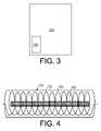
- FIG. 3is a schematic diagram of an embodiment of an electromotive rectification system integrated with an electric power distribution panel.
- FIG. 4is a schematic diagram of an alternate embodiment of a first coil unit.
- FIG. 5Ais a graph showing power consumption recorded at a breaker box connected to a single appliance operating over time without the invention being employed.
- FIG. 5Bis a graph showing power consumption recorded at a breaker box connected to a single appliance operating over time with the invention being employed.
- one representative embodiment of a electromotive rectification system 100includes a housing 110 , preferably made of a conductive material such as a metal that is grounded, in which is disposed a first coil unit 120 and a spaced-apart second coil unit 130 .
- the housing 110could include a non-conductive material, such as a plastic or fiberglass.
- the first coil unit 120includes a non-insulated conductive coil 122 .
- the coil 122includes a 10-gauge or a 12-gauge solid copper wire coil including about 13 to 14 turns and having an inside diameter of about 5/16 inches.
- a first contact 128extends from the housing 110 .
- the coil 122is disposed in a non-conductive tube 124 , such as a poly-vinyl chloride (PVC) tube 124 and is suspended in micro-scale ferrous filings 126 .
- PVCpoly-vinyl chloride
- the second coil unit 130includes an insulated conductive coil 132 .
- the coil 132includes a 10-gauge or a 12-gauge solid copper or aluminum wire coil including about 13 to 14 turns and having an inside diameter of about 5/16 inches.
- a second contact 138extends from the housing 110 .
- the coil 132is disposed in a non-conductive tube, such as a poly-vinyl chloride (PVC) tube 134 and is suspended in air 136 or another insulating medium.
- PVCpoly-vinyl chloride
- first coil unit 120 and the second coil unit 130are shown being disposed in parallel in the housing 110 , the relative orientation of these units is not important.
- the coil units 120 and 130may be suspended in an insulating material 112 , such as epoxy, to provide mechanical stability to the units.
- the electromotive rectification system 100is coupled to a breaker panel 200 (sometimes referred to as an “electric power distribution panel”).
- the breaker panel 200would typically include several inside power cables 202 , each including a hot wire 212 , a ground wire 214 and a neutral wire 216 .
- Each hot wire 212is coupled to a breaker 210 , which is coupled to a hot power bus bar 206 .
- Each ground wire 214is coupled to a ground bus bar 208 that is grounded.
- Each neutral wire 216is coupled to a neutral bus bar 220 .
- An outside cable 204brings electricity from a power utility to the breaker panel 200 .
- the outside cableincludes an outside hot wire 230 and an outside neutral wire 232 .
- the first contact 128is coupled neutral bus bar 220 at a first neutral contact 222 and the second contact 138 is coupled neutral bus bar 220 at a second neutral contact 224 .
- the first neutral contact 222is electrically spaced apart from the second neutral contact 224 so that all neutral wires 216 contact the neutral bus bar 220 between the first neutral contact 222 and the second neutral contact 224 .
- the electromotive rectification system 100may be integrated with the breaker panel 200 .
- the first coil unit 120would not employ ferrous filings, but would employ a mag wire coil 300 that is electrically isolated from the coil 122 .
- FIGS. 5A-5Apower consumption during a four minute period was recorded at a breaker box while a single household appliance was operated.
- the power consumption 500shown in FIG. 5A
- the inventionwas not connected to the breaker box was about 5% greater than the power consumption 502 , shown in FIG. 5B , while the invention was connected to the breaker box.
Landscapes
- Engineering & Computer Science (AREA)
- Power Engineering (AREA)
- Distribution Board (AREA)
- Patch Boards (AREA)
Abstract
Description
- This application claims the benefit of U.S. Provisional Patent Application Ser. No. 61/083,402, filed Jul. 24, 2008, the entirety of which is hereby incorporated herein by reference.
- 1. Field of the Invention
- The present invention relates to electrical systems and, more specifically, to an electrical system used in cooperation with an electrical power distribution system.
- 2. Description of the Prior Art
- Electrical power systems typically employ a “hot” electrical conductor that delivers current to a location and a “neutral” conductor that allows return of electrical current to its source. Due to mechanical inefficiencies in many household appliances and in industrial machinery, short transient variations in return current can be experienced on the neutral conductor. These transients can make electrical power usage less efficient.
- Therefore, there is a need for a system that minimizes the effects of power transients on neutral conductors.
- The disadvantages of the prior art are overcome by the present invention which, in one aspect, is an AC neutral bus electromotive power rectification unit that includes a first coil unit and a second coil unit. The first coil unit includes a first conductive wire coil having a first end and an opposite second end. The conductive coil is disposed in a first non-conductive tube and is suspended in a ferrous matrix. The second coil unit includes a second conductive wire coil having a first end and an opposite second end. The first end of the second coil unit is electrically coupled to the first end of the first coil unit. The second coil unit is disposed in a second non-conductive tube and is surrounded by a non-conductive material.
- In another aspect, the invention is an AC neutral bus electromotive power rectification device for use with a neutral bus bar in an electrical power distribution box, in which a plurality of inside neutral wires are coupled to the neutral bus bar and in which one outside neutral wire is coupled to the neutral bus bar. A first coil unit includes a first conductive wire coil having a first end and an opposite second end, The conductive coil is disposed in a first non-conductive tube and is suspended in a ferrous matrix. The second end of the first coil unit is electrically coupled to the neutral bus bar at a first position in which every neutral wire coupled to the neutral bus bar lies between the first position and a second position at which an outside neutral wire is coupled to the neutral bus bar. The second coil unit includes a second conductive wire coil having a first end and an opposite second end. The first end of the second coil unit is electrically coupled to the first end of the first coil unit. The second coil unit is disposed in a second non-conductive tube and is surrounded by a non-conductive material. The second end of the second coil unit is electrically coupled to the second position at which an outside neutral wire is coupled to the neutral bus bar.
- In yet another aspect, the invention is an electrical power distribution unit that includes an electrical power distribution box, which includes a neutral bus bar. A plurality of inside neutral wires is coupled to the neutral bus bar between a first position and an opposite second position. An outside neutral wire is coupled to the neutral bus bar adjacent to the second position. A first coil unit includes a first conductive wire coil having a first end and an opposite second end. The conductive coil is disposed in a first non-conductive tube and is suspended in a ferrous matrix. The second end of the first coil unit is electrically coupled to the neutral bus bar at the first position. A second coil unit includes a second conductive wire coil having a first end and an opposite second end. The first end of the second coil unit is electrically coupled to the first end of the first coil unit. The second coil unit is disposed in a second non-conductive tube and is surrounded by a non-conductive material. The second end of the second coil unit is electrically coupled to adjacent to the second position. The first coil unit and the second coil unit are both disposed in a housing. The housing is filled with an insulating material.
- These and other aspects of the invention will become apparent from the following description of the preferred embodiments taken in conjunction with the following drawings. As would be obvious to one skilled in the art, many variations and modifications of the invention may be effected without departing from the spirit and scope of the novel concepts of the disclosure.
FIG. 1 is a schematic diagram of an embodiment of an electromotive rectification system.FIG. 2 is a schematic diagram of an embodiment of an electromotive rectification system coupled to an electric power distribution panel.FIG. 3 is a schematic diagram of an embodiment of an electromotive rectification system integrated with an electric power distribution panel.FIG. 4 is a schematic diagram of an alternate embodiment of a first coil unit.FIG. 5A is a graph showing power consumption recorded at a breaker box connected to a single appliance operating over time without the invention being employed.FIG. 5B is a graph showing power consumption recorded at a breaker box connected to a single appliance operating over time with the invention being employed.- A preferred embodiment of the invention is now described in detail. Referring to the drawings, like numbers indicate like parts throughout the views. Unless otherwise specifically indicated in the disclosure that follows, the drawings are not necessarily drawn to scale. As used in the description herein and throughout the claims, the following terms take the meanings explicitly associated herein, unless the context clearly dictates otherwise: the meaning of “an,” and “the” includes plural reference, the meaning of “in” includes “in” and “on.”
- As shown in
FIG. 1 , one representative embodiment of aelectromotive rectification system 100 includes ahousing 110, preferably made of a conductive material such as a metal that is grounded, in which is disposed afirst coil unit 120 and a spaced-apartsecond coil unit 130. In an alternate embodiment, thehousing 110 could include a non-conductive material, such as a plastic or fiberglass. - The
first coil unit 120 includes a non-insulatedconductive coil 122. In a residential embodiment, thecoil 122 includes a 10-gauge or a 12-gauge solid copper wire coil including about 13 to 14 turns and having an inside diameter of about 5/16 inches. Afirst contact 128 extends from thehousing 110. Thecoil 122 is disposed in anon-conductive tube 124, such as a poly-vinyl chloride (PVC)tube 124 and is suspended in micro-scale ferrous filings126. - The
second coil unit 130 includes an insulated conductive coil132. In a residential embodiment, the coil132 includes a 10-gauge or a 12-gauge solid copper or aluminum wire coil including about 13 to 14 turns and having an inside diameter of about 5/16 inches. Asecond contact 138 extends from thehousing 110. The coil132 is disposed in a non-conductive tube, such as a poly-vinyl chloride (PVC) tube134 and is suspended in air136 or another insulating medium. - While the
first coil unit 120 and thesecond coil unit 130 are shown being disposed in parallel in thehousing 110, the relative orientation of these units is not important. Thecoil units material 112, such as epoxy, to provide mechanical stability to the units. - As shown in
FIG. 2 , theelectromotive rectification system 100 is coupled to a breaker panel200 (sometimes referred to as an “electric power distribution panel”). Thebreaker panel 200 would typically include severalinside power cables 202, each including a hot wire212, aground wire 214 and a neutral wire216. Each hot wire212 is coupled to abreaker 210, which is coupled to a hotpower bus bar 206. Eachground wire 214 is coupled to aground bus bar 208 that is grounded. Each neutral wire216 is coupled to aneutral bus bar 220. - An
outside cable 204 brings electricity from a power utility to thebreaker panel 200. The outside cable includes an outsidehot wire 230 and an outsideneutral wire 232. - The
first contact 128 is coupledneutral bus bar 220 at a firstneutral contact 222 and thesecond contact 138 is coupledneutral bus bar 220 at a secondneutral contact 224. The firstneutral contact 222 is electrically spaced apart from the secondneutral contact 224 so that all neutral wires216 contact theneutral bus bar 220 between the firstneutral contact 222 and the secondneutral contact 224. - As shown in
FIG. 3 , theelectromotive rectification system 100 may be integrated with thebreaker panel 200. - As shown in
FIG. 4 , in one alternate embodiment, thefirst coil unit 120 would not employ ferrous filings, but would employ amag wire coil 300 that is electrically isolated from thecoil 122. - In one experimental embodiment, as shown in
FIGS. 5A-5A power consumption during a four minute period was recorded at a breaker box while a single household appliance was operated. Thepower consumption 500, shown inFIG. 5A , while the invention was not connected to the breaker box was about 5% greater than thepower consumption 502, shown inFIG. 5B , while the invention was connected to the breaker box. - The above described embodiments, while including the preferred embodiment and the best mode of the invention known to the inventor at the time of filing, are given as illustrative examples only. It will be readily appreciated that many deviations may be made from the specific embodiments disclosed in this specification without departing from the spirit and scope of the invention. Accordingly, the scope of the invention is to be determined by the claims below rather than being limited to the specifically described embodiments above.
Claims (19)
Priority Applications (1)
| Application Number | Priority Date | Filing Date | Title |
|---|---|---|---|
| US12/504,763US7948342B2 (en) | 2008-07-24 | 2009-07-17 | Electromotive rectification system |
Applications Claiming Priority (2)
| Application Number | Priority Date | Filing Date | Title |
|---|---|---|---|
| US8340208P | 2008-07-24 | 2008-07-24 | |
| US12/504,763US7948342B2 (en) | 2008-07-24 | 2009-07-17 | Electromotive rectification system |
Publications (2)
| Publication Number | Publication Date |
|---|---|
| US20100033283A1true US20100033283A1 (en) | 2010-02-11 |
| US7948342B2 US7948342B2 (en) | 2011-05-24 |
Family
ID=41652365
Family Applications (1)
| Application Number | Title | Priority Date | Filing Date |
|---|---|---|---|
| US12/504,763Active2029-07-30US7948342B2 (en) | 2008-07-24 | 2009-07-17 | Electromotive rectification system |
Country Status (1)
| Country | Link |
|---|---|
| US (1) | US7948342B2 (en) |
Cited By (2)
| Publication number | Priority date | Publication date | Assignee | Title |
|---|---|---|---|---|
| US20110116212A1 (en)* | 2009-10-29 | 2011-05-19 | Rosemore Timothy A | Method of Recovering Power Losses In A Residential, Commercial, or Industrial Facility |
| US20160325946A1 (en)* | 2015-05-04 | 2016-11-10 | Applied Materials, Inc. | Substrate rotary loader |
Families Citing this family (19)
| Publication number | Priority date | Publication date | Assignee | Title |
|---|---|---|---|---|
| EP3140838B1 (en)* | 2014-05-05 | 2021-08-25 | 3D Glass Solutions, Inc. | Inductive device in a photo-definable glass structure |
| KR20180134868A (en) | 2016-02-25 | 2018-12-19 | 3디 글래스 솔루션즈 인코포레이티드 | A photoactive substrate for fabricating 3D capacitors and capacitor arrays |
| US12165809B2 (en) | 2016-02-25 | 2024-12-10 | 3D Glass Solutions, Inc. | 3D capacitor and capacitor array fabricating photoactive substrates |
| US11161773B2 (en) | 2016-04-08 | 2021-11-02 | 3D Glass Solutions, Inc. | Methods of fabricating photosensitive substrates suitable for optical coupler |
| KR102273624B1 (en) | 2017-04-28 | 2021-07-07 | 3디 글래스 솔루션즈 인코포레이티드 | Rf Circulator |
| KR102418671B1 (en) | 2017-07-07 | 2022-07-12 | 3디 글래스 솔루션즈 인코포레이티드 | 2d and 3d rf lumped element devices for rf system in a package photoactive glass substrates |
| KR102504067B1 (en)* | 2017-12-07 | 2023-02-27 | 삼성전기주식회사 | Thin type coil component |
| JP7008824B2 (en) | 2017-12-15 | 2022-01-25 | スリーディー グラス ソリューションズ,インク | Connection transmission line resonant RF filter |
| EP3735743A4 (en) | 2018-01-04 | 2021-03-03 | 3D Glass Solutions, Inc. | Impedance matching conductive structure for high efficiency rf circuits |
| EP3643148A4 (en) | 2018-04-10 | 2021-03-31 | 3D Glass Solutions, Inc. | INTEGRATED RF POWER CONDITIONING CAPACITOR |
| US11424069B2 (en) | 2018-04-23 | 2022-08-23 | Line Loss Pro Llc | Alternating current neutral and ground inductive electromagnetic rectification apparatus |
| US10903545B2 (en) | 2018-05-29 | 2021-01-26 | 3D Glass Solutions, Inc. | Method of making a mechanically stabilized radio frequency transmission line device |
| US11139582B2 (en) | 2018-09-17 | 2021-10-05 | 3D Glass Solutions, Inc. | High efficiency compact slotted antenna with a ground plane |
| AU2019416327B2 (en) | 2018-12-28 | 2021-12-09 | 3D Glass Solutions, Inc. | Annular capacitor RF, microwave and MM wave systems |
| AU2019416325A1 (en) | 2018-12-28 | 2021-02-04 | 3D Glass Solutions, Inc. | Heterogenous integration for RF, microwave and mm wave systems in photoactive glass substrates |
| JP7140435B2 (en) | 2019-04-05 | 2022-09-21 | スリーディー グラス ソリューションズ,インク | Glass-based empty substrate integrated waveguide device |
| KR102601781B1 (en) | 2019-04-18 | 2023-11-14 | 3디 글래스 솔루션즈 인코포레이티드 | High efficiency die dicing and release |
| KR20220164800A (en) | 2020-04-17 | 2022-12-13 | 3디 글래스 솔루션즈 인코포레이티드 | broadband inductor |
| WO2024233737A2 (en) | 2023-05-09 | 2024-11-14 | Energy Eight, Llc | A neutral and/or ground harmonic filter system |
Citations (6)
| Publication number | Priority date | Publication date | Assignee | Title |
|---|---|---|---|---|
| US5371466A (en)* | 1992-07-29 | 1994-12-06 | The Regents Of The University Of California | MRI RF ground breaker assembly |
| US20030214313A1 (en)* | 2002-04-18 | 2003-11-20 | Kabushiki Kaisha Toshiba | Current detection equipment and semiconductor device |
| US20050012581A1 (en)* | 2003-06-12 | 2005-01-20 | Nec Tokin Corporation | Coil component and fabricaiton method of the same |
| US7312686B2 (en)* | 2004-07-07 | 2007-12-25 | Veris Industries, Llc | Split core sensing transformer |
| US20080001693A1 (en)* | 2006-06-29 | 2008-01-03 | Jae-Hong Hahn | Configurable multiphase coupled magnetic structure |
| US20080266042A1 (en)* | 2007-04-27 | 2008-10-30 | Fuji Electric Device Technology Co., Ltd | Transformer unit, and power converting device |
- 2009
- 2009-07-17USUS12/504,763patent/US7948342B2/enactiveActive
Patent Citations (6)
| Publication number | Priority date | Publication date | Assignee | Title |
|---|---|---|---|---|
| US5371466A (en)* | 1992-07-29 | 1994-12-06 | The Regents Of The University Of California | MRI RF ground breaker assembly |
| US20030214313A1 (en)* | 2002-04-18 | 2003-11-20 | Kabushiki Kaisha Toshiba | Current detection equipment and semiconductor device |
| US20050012581A1 (en)* | 2003-06-12 | 2005-01-20 | Nec Tokin Corporation | Coil component and fabricaiton method of the same |
| US7312686B2 (en)* | 2004-07-07 | 2007-12-25 | Veris Industries, Llc | Split core sensing transformer |
| US20080001693A1 (en)* | 2006-06-29 | 2008-01-03 | Jae-Hong Hahn | Configurable multiphase coupled magnetic structure |
| US20080266042A1 (en)* | 2007-04-27 | 2008-10-30 | Fuji Electric Device Technology Co., Ltd | Transformer unit, and power converting device |
Cited By (3)
| Publication number | Priority date | Publication date | Assignee | Title |
|---|---|---|---|---|
| US20110116212A1 (en)* | 2009-10-29 | 2011-05-19 | Rosemore Timothy A | Method of Recovering Power Losses In A Residential, Commercial, or Industrial Facility |
| WO2011059804A3 (en)* | 2009-10-29 | 2011-11-17 | Gig2 Group, Inc. | Method of recovering power losses in a residential, commercial or industrial facility |
| US20160325946A1 (en)* | 2015-05-04 | 2016-11-10 | Applied Materials, Inc. | Substrate rotary loader |
Also Published As
| Publication number | Publication date |
|---|---|
| US7948342B2 (en) | 2011-05-24 |
Similar Documents
| Publication | Publication Date | Title |
|---|---|---|
| US7948342B2 (en) | Electromotive rectification system | |
| CN102033165B (en) | Rogowski coil, comprises the middle pressure electrical equipment of this coil and provides the method for electrostatic screening for this coil | |
| US20080099227A1 (en) | Power cord with a leakage current detection conductor | |
| EP2333788A3 (en) | High frequency electric wire | |
| EP2112749A3 (en) | Motor-driven compressor | |
| NZ591407A (en) | Electrical machine with dual insulated coil assembly | |
| CN101867201B (en) | A kind of battery charger | |
| WO2021090083A1 (en) | Pipeline electric heating system | |
| CN200965819Y (en) | Inner shielding combination transposing wire | |
| CN106229063B (en) | Power line and electric equipment | |
| CN101467219B (en) | High current cable | |
| CN107123521A (en) | Power transformer based on graphene wire | |
| CN209419178U (en) | Transmission line of electricity pipeline and gas-insulated lines | |
| CN106229065B (en) | Power line and electric equipment | |
| CN212435048U (en) | Insulation threading board for switchgear | |
| CN102436871A (en) | Connecting wire used for intermediate frequency power supply current transformer and equipment | |
| CN205789199U (en) | Computer cable | |
| CN207425587U (en) | Reactor | |
| CN202434247U (en) | Connection conducting wire for middle-frequency power supply current transformer and device | |
| CN205920863U (en) | High voltage insulation sheath and dry -type transformer | |
| CN114270649A (en) | Protection of AC Equipment | |
| CN206225183U (en) | Transformer grounding resistance device | |
| CN202444062U (en) | Fixing device for inserted electric connection of multi-core leads | |
| CN203850043U (en) | High-conductive creep-resistant aluminum alloy conductor crosslinked polyethylene power cable | |
| CN201498248U (en) | Flat electric cable |
Legal Events
| Date | Code | Title | Description |
|---|---|---|---|
| AS | Assignment | Owner name:CUTT-A-WATT ENTERPRISES, LLC,GEORGIA Free format text:ASSIGNMENT OF ASSIGNORS INTEREST;ASSIGNOR:LONG, JOHN M.;REEL/FRAME:023552/0561 Effective date:20090716 Owner name:CUTT-A-WATT ENTERPRISES, LLC, GEORGIA Free format text:ASSIGNMENT OF ASSIGNORS INTEREST;ASSIGNOR:LONG, JOHN M.;REEL/FRAME:023552/0561 Effective date:20090716 | |
| STCF | Information on status: patent grant | Free format text:PATENTED CASE | |
| FPAY | Fee payment | Year of fee payment:4 | |
| MAFP | Maintenance fee payment | Free format text:PAYMENT OF MAINTENANCE FEE, 8TH YR, SMALL ENTITY (ORIGINAL EVENT CODE: M2552); ENTITY STATUS OF PATENT OWNER: SMALL ENTITY Year of fee payment:8 | |
| FEPP | Fee payment procedure | Free format text:MAINTENANCE FEE REMINDER MAILED (ORIGINAL EVENT CODE: REM.); ENTITY STATUS OF PATENT OWNER: SMALL ENTITY | |
| FEPP | Fee payment procedure | Free format text:11.5 YR SURCHARGE- LATE PMT W/IN 6 MO, SMALL ENTITY (ORIGINAL EVENT CODE: M2556); ENTITY STATUS OF PATENT OWNER: SMALL ENTITY | |
| MAFP | Maintenance fee payment | Free format text:PAYMENT OF MAINTENANCE FEE, 12TH YR, SMALL ENTITY (ORIGINAL EVENT CODE: M2553); ENTITY STATUS OF PATENT OWNER: SMALL ENTITY Year of fee payment:12 |