US20100022821A1 - Method and system for improving diastolic function of the heart - Google Patents
Method and system for improving diastolic function of the heartDownload PDFInfo
- Publication number
- US20100022821A1 US20100022821A1US12/311,222US31122207AUS2010022821A1US 20100022821 A1US20100022821 A1US 20100022821A1US 31122207 AUS31122207 AUS 31122207AUS 2010022821 A1US2010022821 A1US 2010022821A1
- Authority
- US
- United States
- Prior art keywords
- attachment
- elements
- heart
- elastic
- wall
- Prior art date
- Legal status (The legal status is an assumption and is not a legal conclusion. Google has not performed a legal analysis and makes no representation as to the accuracy of the status listed.)
- Granted
Links
Images


Classifications
- A—HUMAN NECESSITIES
- A61—MEDICAL OR VETERINARY SCIENCE; HYGIENE
- A61F—FILTERS IMPLANTABLE INTO BLOOD VESSELS; PROSTHESES; DEVICES PROVIDING PATENCY TO, OR PREVENTING COLLAPSING OF, TUBULAR STRUCTURES OF THE BODY, e.g. STENTS; ORTHOPAEDIC, NURSING OR CONTRACEPTIVE DEVICES; FOMENTATION; TREATMENT OR PROTECTION OF EYES OR EARS; BANDAGES, DRESSINGS OR ABSORBENT PADS; FIRST-AID KITS
- A61F2/00—Filters implantable into blood vessels; Prostheses, i.e. artificial substitutes or replacements for parts of the body; Appliances for connecting them with the body; Devices providing patency to, or preventing collapsing of, tubular structures of the body, e.g. stents
- A61F2/02—Prostheses implantable into the body
- A61F2/24—Heart valves ; Vascular valves, e.g. venous valves; Heart implants, e.g. passive devices for improving the function of the native valve or the heart muscle; Transmyocardial revascularisation [TMR] devices; Valves implantable in the body
- A61F2/2478—Passive devices for improving the function of the heart muscle, i.e. devices for reshaping the external surface of the heart, e.g. bags, strips or bands
- A61F2/2481—Devices outside the heart wall, e.g. bags, strips or bands
- A—HUMAN NECESSITIES
- A61—MEDICAL OR VETERINARY SCIENCE; HYGIENE
- A61B—DIAGNOSIS; SURGERY; IDENTIFICATION
- A61B17/00—Surgical instruments, devices or methods
- A61B17/00234—Surgical instruments, devices or methods for minimally invasive surgery
- A—HUMAN NECESSITIES
- A61—MEDICAL OR VETERINARY SCIENCE; HYGIENE
- A61B—DIAGNOSIS; SURGERY; IDENTIFICATION
- A61B17/00—Surgical instruments, devices or methods
- A61B17/064—Surgical staples, i.e. penetrating the tissue
- A61B17/0644—Surgical staples, i.e. penetrating the tissue penetrating the tissue, deformable to closed position
- A—HUMAN NECESSITIES
- A61—MEDICAL OR VETERINARY SCIENCE; HYGIENE
- A61B—DIAGNOSIS; SURGERY; IDENTIFICATION
- A61B17/00—Surgical instruments, devices or methods
- A61B17/04—Surgical instruments, devices or methods for suturing wounds; Holders or packages for needles or suture materials
- A61B17/0401—Suture anchors, buttons or pledgets, i.e. means for attaching sutures to bone, cartilage or soft tissue; Instruments for applying or removing suture anchors
- A—HUMAN NECESSITIES
- A61—MEDICAL OR VETERINARY SCIENCE; HYGIENE
- A61B—DIAGNOSIS; SURGERY; IDENTIFICATION
- A61B17/00—Surgical instruments, devices or methods
- A61B17/068—Surgical staplers, e.g. containing multiple staples or clamps
- A—HUMAN NECESSITIES
- A61—MEDICAL OR VETERINARY SCIENCE; HYGIENE
- A61B—DIAGNOSIS; SURGERY; IDENTIFICATION
- A61B17/00—Surgical instruments, devices or methods
- A61B17/00234—Surgical instruments, devices or methods for minimally invasive surgery
- A61B2017/00238—Type of minimally invasive operation
- A61B2017/00243—Type of minimally invasive operation cardiac
- A—HUMAN NECESSITIES
- A61—MEDICAL OR VETERINARY SCIENCE; HYGIENE
- A61B—DIAGNOSIS; SURGERY; IDENTIFICATION
- A61B17/00—Surgical instruments, devices or methods
- A61B17/064—Surgical staples, i.e. penetrating the tissue
- A61B2017/0647—Surgical staples, i.e. penetrating the tissue having one single leg, e.g. tacks
- A—HUMAN NECESSITIES
- A61—MEDICAL OR VETERINARY SCIENCE; HYGIENE
- A61B—DIAGNOSIS; SURGERY; IDENTIFICATION
- A61B17/00—Surgical instruments, devices or methods
- A61B17/064—Surgical staples, i.e. penetrating the tissue
- A61B2017/0649—Coils or spirals
- A—HUMAN NECESSITIES
- A61—MEDICAL OR VETERINARY SCIENCE; HYGIENE
- A61F—FILTERS IMPLANTABLE INTO BLOOD VESSELS; PROSTHESES; DEVICES PROVIDING PATENCY TO, OR PREVENTING COLLAPSING OF, TUBULAR STRUCTURES OF THE BODY, e.g. STENTS; ORTHOPAEDIC, NURSING OR CONTRACEPTIVE DEVICES; FOMENTATION; TREATMENT OR PROTECTION OF EYES OR EARS; BANDAGES, DRESSINGS OR ABSORBENT PADS; FIRST-AID KITS
- A61F2/00—Filters implantable into blood vessels; Prostheses, i.e. artificial substitutes or replacements for parts of the body; Appliances for connecting them with the body; Devices providing patency to, or preventing collapsing of, tubular structures of the body, e.g. stents
- A61F2/02—Prostheses implantable into the body
- A61F2/24—Heart valves ; Vascular valves, e.g. venous valves; Heart implants, e.g. passive devices for improving the function of the native valve or the heart muscle; Transmyocardial revascularisation [TMR] devices; Valves implantable in the body
- A61F2/2478—Passive devices for improving the function of the heart muscle, i.e. devices for reshaping the external surface of the heart, e.g. bags, strips or bands
- A61F2/2481—Devices outside the heart wall, e.g. bags, strips or bands
- A61F2002/2484—Delivery devices therefor
- A—HUMAN NECESSITIES
- A61—MEDICAL OR VETERINARY SCIENCE; HYGIENE
- A61F—FILTERS IMPLANTABLE INTO BLOOD VESSELS; PROSTHESES; DEVICES PROVIDING PATENCY TO, OR PREVENTING COLLAPSING OF, TUBULAR STRUCTURES OF THE BODY, e.g. STENTS; ORTHOPAEDIC, NURSING OR CONTRACEPTIVE DEVICES; FOMENTATION; TREATMENT OR PROTECTION OF EYES OR EARS; BANDAGES, DRESSINGS OR ABSORBENT PADS; FIRST-AID KITS
- A61F2250/00—Special features of prostheses classified in groups A61F2/00 - A61F2/26 or A61F2/82 or A61F9/00 or A61F11/00 or subgroups thereof
- A61F2250/0058—Additional features; Implant or prostheses properties not otherwise provided for
- A61F2250/0067—Means for introducing or releasing pharmaceutical products into the body
Definitions
- the present inventionrelates to methods and devices for improving ventricular function of the heart and, more particularly, to in-vivo methods and devices for improving diastolic function of the left ventricle of the heart.
- Heart failureis a complex clinical syndrome that can result from any structural or functional cardiac disorder that impairs the ability of the ventricle to fill with or eject blood.
- the cardinal manifestations of HFare dyspnea and fatigue, which may limit exercise tolerance, and fluid retention, which may lead to pulmonary congestion and peripheral edema.
- Heart failureis most commonly associated with impaired left ventricle (LV) systolic function.
- LVleft ventricle
- EFejection fraction
- EFinjection fraction
- EFnormal value of EF
- EF ⁇ 0.50is commonly used as an indicator of normal systolic function. It is notable, however, that as much as 30-50% of all patients with typical symptoms of congestive heart failure have a normal or slightly reduced ejection fraction, that is, a value of EF ⁇ 0.45.
- DHFdiastolic heart failure
- Primary diastolic dysfunctionis typically observed in patients with hypertension and hypertrophic or restrictive cardiomyopathy, but can also occur in a variety of other clinical disorders and has a particularly high prevalence in the elderly population. Aging is associated with ‘physiologic’ diastolic dysfunction due to the increase in LV muscle mass and changes in passive elastic properties of the myocardium, hence, the concern of an increase in the incidence of diastolic dysfunction as the aging of the western world population progresses.
- the present inventionis directed to a system, method, kit and devices for improving diastolic function of the heart comprising elastic elements configured to be mounted on the wall of the heart by means of attachment elements, said attachment elements are adapted to be threaded into, or anchored in, the wall of the heart, and to provide an anchor for curved fasteners formed at, or attached to, extremities of the elastic elements.
- the systempreferably comprise one or more substantially parallel rows of elastic elements mounted on the wall of the heart by means of the attachment elements, wherein each pair of adjacent elastic elements are engaged in anchoring means of a mutual attachment element.
- the elastic elements of the inventionmay be prepared from conventional materials having known elasticity properties suitable to be used in the system and devices of the invention (e.g., Conichrome (FWM 1058)).
- the present inventionis directed to a system for improving diastolic function of the heart comprising:
- the elastic elementspreferably comprise one or more torsion springs, each of which comprises two arms forming a “V” or “U” like shape.
- the extremities of the elastic elementsare preferably bent to form curved fasteners capable of being engaged in anchoring means provided in the attachment elements.
- the elastic elementscomprise torsion springs and two arms forming a “V”-like shape, wherein each of the arms comprises a curved fastener.
- the curved fastenersmay be shaped in a form of a spiral, or a “G”-like shape, capable of being engaged in anchoring loops provided in the attachment elements.
- the end portion of each armmay be curved into an “S”-like shape, wherein the bottom part of the “S”-like shape is further curved to provide the spiral, or a “G”-like shape curved fastener.
- This configurationmay be advantageously employed for engaging the curved fasteners of adjacent elastic elements at opposing sides of an anchoring loop of an attachment element, such that opposing tangential mechanical forces applied by the adjacent elastic elements over the attachment element are substantially canceled.
- This configurationadvantageously minimizes the wear between the attachment elements and the elastic elements, substantially facilitates the implantation procedure (by attaching the elastic element to the attachment element), and efficiently prevents unintended release of the elastic elements from the attachment elements.
- each elastic elementis comprised of a relatively straight arm and an arm having a curved section relative to the plane of the torsion spring and the relatively straight arm of the elastic element, thereby permitting the crossing of an arm having a curved section of a first elastic element with a relatively straight arm of an adjacent elastic element, while preventing physical contact therebetween.
- At least one of the curved fasteners of the elastic elementsmay comprise one or more fastening loops capable of being placed and tightened over a portion of an anchoring element.
- the other curved fastenermay be provided in a form of an anchoring (closed or semi-closed) loop, such that adjacent elastic elements may be secured to an attachment element by placing the anchoring loop provided in one arm of one of the elastic elements over the anchoring means of the attachment element and thereafter securing it thereto by tightening the one or more fastening loops provided in an arm of the adjacent elastic elements thereupon, over the anchoring means of the attachment element.
- a widening loopmay be provided on, or near, the fastening loops for assisting in widening the fastening loops before placing them over a portion of the anchoring element.
- a saddlemay be formed on an arm section of the elastic element near the curved fasteners for assisting in widening the fastening loops by pulling the widening ring towards the saddle by means of forceps, pliers, or any other instrument suitable for this purpose.
- the elastic elementsare comprised of two “V”-shaped torsion springs having a mutual arm, which form a zigzagged shape element wherein the non-mutual arms are more or less perpendicular and wherein said non-mutual arms comprise curved fasteners configured such that the curved fasteners of two adjacent elastic elements engage opposing sides of an anchoring loop of an attachment element, thereby providing an assembly which substantially cancels opposing mechanical forces applied by adjacent elastic elements over a mutual attachment element.
- the attachment elementsmay be formed in a shape of a helix having an attachment section and a head section, wherein the attachment section is adapted to be threaded into a tissue and the head section comprises the anchoring means.
- the attachment elementmay further comprise a neck section, provided between the attachment section and the head section, said neck section is adapted to prevent excess threading of the attachment element into the tissue.
- the neck sectionis formed by abruptly reducing the distances between the helix loops above the attachment section of the attachment element.
- the anchoring means of the attachment elementsmay be a continuation of the neck section wherein the radius of the helix loops is slightly reduced.
- the anchoring meansare implemented as anchoring loops provided in the attachment element, wherein the plane of the anchoring loop is substantially parallel to, or coincides with, a concentric axis of the attachment element.
- the attachment elementsare a type of intramural anchor having one or more barbs attached to a nail section of the intramural anchor and configured to be introduced into the tissue and prevent departure of the attachment element after it is inserted into the tissue. More particularly, the barbs are pressed along portions of the nail section of the intramural anchor during insertion into the tissue, and thereafter their state is changed into an “open” state by slightly pulling the intramural anchor proximally such that the proximal sides of the barbs are moved radially away from the nail section, while the distal side of the barbs remain attached thereto.
- This attachment elementpreferably comprises anchoring means such as the anchoring loop which plane is substantially parallel to, or coincides with, a concentric axis of the attachment element.
- the attachment elementmay further comprise stoppers provided near the anchoring means and adapted to prevent excessive insertion thereof into the tissue, and to further prevent departure of the attachment element therefrom.
- the present inventionis directed to a device for improving diastolic function of the heart comprising an elastic element comprising one or more torsion springs, each of which comprising two arms forming a “V” or “U” like shape, wherein the extremities of said elastic element are bent to form curved fasteners capable of being engaged in an anchoring loop or ring.
- the device of the present inventionis different from the devices described in WO 2004/066805 by virtue of the curved fasteners formed at the extremities of the device.
- This featureis highly advantageous in that it permits the practitioner to connect a series of such devices in the form of chains or rows along the heart wall.
- the use of substantially parallel rows of the elementshas been found to be particularly advantageous for: preventing restriction of the myocardium, enabling versatility and modularity of the implantation procedure, as well as in increasing the variability of the total force supplied to the myocardium (e.g. a structure of strong medial elastic elements and relatively weaker peripheral elastic elements).
- the systemmay further comprise an elastic wire or stretchable cord capable of being connected to the attachment elements at the extremities of the chain formed of the alternating series of the elastic elements and the attachment elements, wherein said elastic wire or stretchable cord and said chain of elastic elements and attachment elements encircles a perimeter of the heart.
- the systemmay further comprise an inflatable balloon capable of being introduced into a ventricle of the heart and being inflated thereinside, and/or one or more compressible elements adapted to be threaded into the wall of the heart.
- the inventionis directed to a method for improving diastolic function of the heart, comprising:
- attachment elementsmay be attached by means of a gripping tool, as follows:
- the methodmay further comprise mounting additional one or more such chains of alternating series of elastic elements and attachment elements on the wall of the heart, as follows:
- the one or more chains of alternating series of elastic elements and attachment elementsare substantially parallel
- the methodmay further comprise attaching an elastic wire or stretchable cord to the attachment elements at the extremities of the chain formed of the alternating series of the elastic elements and the attachment elements, wherein said elastic wire or stretchable cord and said chain of elastic elements and attachment elements encircles a perimeter of the heart.
- the methodmay further comprise introducing an inflatable balloon into a ventricle of the heart and inflating the same thereinside. Additionally or alternatively, the method may further comprise threading one or more compressible elements into the wall of the heart.
- the inventionis directed to a kit of elements and instruments for mounting a ventricular function assisting system on the wall of a heart, comprising: one or more elastic elements capable of being attached to a wall of a heart, at least two attachment elements capable of being connected to anchoring means provided in said attachment elements, a gripping tool adapted to grip and hold said anchoring means, and one or more distance indicating instrument capable of being used to indicate distances between adjacent attachment elements and/or the distances between interconnected chains of said attachment and elastic elements.
- the kitmay further comprise one or more compressible elements capable of being threaded into the wall of the heart, expandable balloons capable of being introduced into a ventricle of the heart and inflated thereinside, and/or an elastic wire or stretchable cord capable of being connected to the anchoring means of said attachment elements.
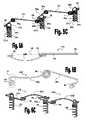
- FIG. 1schematically illustrates a preferred embodiment of the invention comprising a sequence of elastic elements arranged on the outer wall of the left ventricle and an elastic wire or stretchable cord mounted over the outer wall of the right ventricle;
- FIGS. 2A to 2Dschematically illustrate embodiments of an attachment element comprising two or more barbs
- FIGS. 3A and 3Bschematically illustrate an embodiments of the attachment and elastic elements
- FIGS. 3C and 3Dschematically illustrates the attachment of the elastic elements to the attachment elements shown in FIGS. 3A and 3B ;
- FIGS. 4A and 4Billustrate a preferred embodiment of elastic and attachment elements and their connectivity
- FIGS. 5A and 5Brespectively illustrate upper and perspective views of another preferred embodiment of the elastic element and of a respective attachment element
- FIG. 5Cshows a perspective view of the connectivity of elastic and attachment elements shown in FIGS. 5A and 5B ;
- FIGS. 6A to 6Cillustrate yet another preferred embodiment of the elastic element and of its connectivity to a respective attachment element, wherein FIG. 6A is an upper view of the elastic element, FIG. 6B is a perspective view of the attachment element, and FIG. 6C is a perspective view showing the connectivity of the elastic and attachment elements;
- FIG. 7schematically illustrates a preferred embodiment of the attachment elements comprising drug-containing coats
- FIGS. 8A and 8Brespectively show perspective and exploded views of one preferred embodiment of a device for fastening attachment elements to the wall of the heart;
- FIGS. 9A to 9Dillustrate another preferred embodiment of a device for fastening attachment elements to the wall of the heart, wherein FIG. 9A is a perspective view of the device, FIGS. 9B and 9C are perspective views of inner parts of the device, and FIG. 9D is a perspective longitudinal section view of the device;
- FIGS. 10A to 10Cillustrate another preferred embodiment of a device for fastening attachment elements to the wall of the heart, wherein FIG. 10A is a perspective view of the device, FIG. 10B is a perspective longitudinal section view of the device, and FIG. 10C is a perspective view of inner shaft of the device;
- FIGS. 11A to 11Cillustrate another preferred embodiment of a device for fastening attachment elements to the wall of the heart, wherein FIG. 11A is a perspective view of the device, FIG. 11B is a perspective view showing inner parts of the device, and FIG. 11C is a longitudinal section view of a rotatable element of the device;
- FIGS. 12A to 12Fshow perspective views of instruments for guiding the practitioner in determining suitable distances between adjacent attachment elements, and between rows of such elements on the wall of the heart
- FIGS. 12A and 12Billustrate an instrument which may be used for designating two different distances
- FIG. 12Cillustrates an instrument designed for designating a distance and a tolerable deviation
- FIG. 12Dillustrates another embodiment of the instrument shown in FIG. 12C which employs a ring for designating tolerable deviations
- FIG. 12Eillustrates an embodiment of the instrument comprising a closed frame for measuring distances and placing attachment elements
- FIG. 12Fillustrates an embodiment of the instrument, which advantageously enables simple and accurate use and handling by the surgeon;
- FIG. 13illustrates a preferred embodiment for treating ventricular dysfunctions which employs compressible elements that are threaded into the wall of the heart.
- FIG. 14illustrates a device for treating ventricular dysfunctions by means of an inflatable balloon.
- the present inventionprovides various embodiments of ventricular function assisting devices designed for treating diastolic and/or systolic dysfunctions.
- the devices of the inventionare designed to assist in the operation of the heart by aiding in reducing the pressures thereinside during systolic function, and aiding in increasing the pressure during diastolic function.
- the present inventionfurther provides means for mounting a ventricular function assisting device of the invention on the wall of the heart of a treated subject.
- FIG. 1illustrates a preferred embodiment of the invention wherein a sequence of elastic elements 13 are mounted over the outer wall of the left ventricle (L), and an elastic wire or stretchable cord 17 is mounted over the outer wall of the right ventricle (R), of heart 10 , by means of attachment elements 15 .
- Elastic elements 13preferably have a “U” or “V” like shape which arms include detachable means at their ends for detachably connecting them to the attachment elements 15 .
- Attachment elements 15may be attached on, or threaded into, the wall of the heart 10 in a lined sequence having suitable gaps for mounting one or more elastic elements 13 between each pair of consecutive attachment elements 15 .
- Attachment elements 15may be configured in a form of a screw that can be threaded into the wall of the heart, or alternatively, these elements may be manufactured in a form of a nail comprising barbs, preferably circumferential barbs along its axis, to allow placement thereof into the heart wall by pushing it into the wall of the heart, such that said barbs prevents its departure therefrom.
- the distal (leading) end portion of the attachment elementmay be manufactured from a relatively flexible or elastic material, such as, but not limited to, Nitinol, a type of Cobalt alloy, or stainless still, formed in a helical spring-like shape, such that said distal end portion may be compressed and elongated axially within the heart wall responsive to the systolic and diastolic cycles, respectively.
- a relatively flexible or elastic materialsuch as, but not limited to, Nitinol, a type of Cobalt alloy, or stainless still, formed in a helical spring-like shape, such that said distal end portion may be compressed and elongated axially within the heart wall responsive to the systolic and diastolic cycles, respectively.
- the flexible/elastic distal (leading) end portion of the attachment elementmay be manufactured from an absorvable material (e.g., PLLA, PGA, PLA), and/or a suitable polymer, thus providing an attachment element having a stretchable axial length that can be stretched and compressed in response to the diastolic and systolic cycles.
- absorvable materiale.g., PLLA, PGA, PLA
- the one or more rows of lined elastic elements 13are arranged over the left ventricle of the heart in order to improve diastolic function.
- the one or more rows of lined elastic elements 13are preferably arranged such that the attachment elements 15 s at the extremities of each lined sequence are attached on, or threaded into, the wall of the heart at opposing sides of the septum (S) in order to encircle the LV and in this way attain coverage of the LV wall.
- the elastic elementadvantageously stretches the septum which in turn increases the volume of the LV.
- each of the rows of lined elastic elementsconsists of 4 to 7 (depending of the size of the treated heart) elastic elements 13 , wherein the force applied by the elastic elements 13 s mounted near the septum is generally about, but not limited to, 45 ⁇ 5 grams, and the force applied by the intermediate elastic elements 13 about (but not limited to) 70 ⁇ 10 grams.
- Elastic wire or stretchable cord 17may be mounted over the outer wall of the right ventricle (R) of the heart 10 to further assist heart dilatation during diastol. Elastic wire or stretchable cord 17 may be detachably attached to the attachment elements 15 s at the extremities of each lined sequence of elastic elements 13 .
- the “C” shaped elastic wire 17is preferably made from a type of elastic biocompatible metal or plastic, such as, but not limited to, stainless steel, Nitinol, suitable alloy or composite compound, preferably from stainless steel, suitable polymer, or an absorvable material (e.g., PLLA, PGA, PLA).
- the “C” shaped elastic wire 17may be formed in a shape of a spiral wound metal wire made from one of the aforementioned metals of from a suitable alloy.
- elastic wire 17mainly applies radial forces generally in the range of, but not limited to, 125 ⁇ 75 grams on the attachment elements 15 s located at the opposing sides of the septum (S).
- Elastic wire 17 connected to attachment elements 15 s placed at opposing sides of the septumstretches the septum, which surface area is generally about 30% of the surface area of the heart, and thus advantageously increases the volume of the LV.
- stretchable cord 17is preferably made from a type of biocompatible rubber or elastic plastic material, such as, but not limited to, silicon or rubber, preferably from silicon or rubber.
- stretchable cord 17applies pressure over the wall of the heart 10 which advantageously reduces the output of the right ventricle and therefore reduces the risk for pulmonary congestion and edema.
- stretchable cord 17applies pressure on the wall of the right ventricle, and during the diastolic cycle stretchable cord 17 is stretched such that it applies pressure on the wall of the right ventricle and at the same time stretches the septum such that the volume of the LV increases.
- the force applied by stretchable cord 17 on the wall of the right ventriclereduces the output of the right ventricle and thus reduces the risk of pulmonary edema and the overall blood pressures in the heart.
- FIGS. 2A to 2Cschematically illustrate a preferred embodiment of an attachment element 7 comprising two or more barbs 7 b .
- FIG. 2Aillustrates attachment element 7 before attaching it to tissue 3 (e.g., the wall of the heat).
- Attachment element 7comprises a nail section 7 a having a sharp distal end capable of puncturing and penetrating a tissue, and a head section 7 c , attached or formed at the proximal end (relative to the practitioner during attachment thereof) of attachment element 7 , said head section is configured to receive and hold detachable means of elastic elements 15 .
- barbs 7 bare capable of changing their state relative to nail portion 7 a of attachment element 7 , between an opened state (illustrated in FIGS. 2A and 2C ) and a closed state (illustrated in FIG. 2B ).
- FIG. 2Billustrates attachment element 7 during the attachment to tissue 3 , during which the sharp distal end of nail section 7 a punctures and penetrates into tissue 3 , which causes barbs 7 b to change into a closed state.
- FIG. 2Cillustrating attachment element after it is attached to tissue 3
- barbs 7 bchange into an open state responsive to slightly pulling attachment element 7 backwardly (proximally). This mechanism anchors attachment element 7 in its attachment location and effectively prevents its departure from tissue 3 .
- Attachment elementmay be manufactured by wire pulling or laser cutting from a type of metallic material, such as, but not limited to, stainless steel, cobalt alloy, or nitinol, preferably from nitinol.
- the length of nail section 7 amay generally be in the range of 10 to 30 mm, preferably about 20 mm, and its diameter is preferably in the range of 0.1 to 1.5 mm
- Barbs 7 bmay be implemented by means of a doubled wire configuration attached to nail section 7 a , such that one wire of the doubled wire assembly is used for implementing a first barb and the other wire is used for implementing a second barb 7 b .
- the lengths of barbs 7 bmay generally be in the range of 2 to 20 mm.
- FIG. 2Dschematically illustrates another preferred embodiment of an attachment element 8 , which further comprises a stopper 8 d attached to nail section 8 a , near the head section 8 c of attachment element 8 .
- Stopper 8 dcan be implemented by number of (e.g., 2 or 3) slanted arms (or by a conical member) connected to nail section 8 a near head section. These slanted arms, or conical member, form a skirt shape in profile which tapers toward its connection point on nail section 8 a , for preventing excessive insertion of nail section 8 a into tissue 3 , thereby preventing changing the state of barbs 8 b into a closed state, after attachment to tissue 3 . In this way, stoppers 8 d secure attachment element 8 in its attachment point, and prevent unintended departure thereof.
- Stopper 8 dmay be manufactured from, for example, stainless steel, cobalt alloy or nitinol, preferably from nitinol.
- the length and angle relative to nail section 8 a , of stopper 8 dshould be configured to allow penetration of a suitable length (e.g., 1 to 10 mm) of nail section into tissue 3 .
- a suitable lengthe.g. 1 to 10 mm
- the length of stopper 8 dmay be about 5 to 30 mm, and its angle about 45° to 135°.
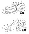
- FIGS. 3A to 3Dillustrate one preferred embodiment of an elastic element 13 a and of attachment elements 15 suitable for mounting the same over the wall of the heart 10 .
- elastic element 13 ais preferably made from an elastic wire formed in a “V”-like shape having spring loop(s) 30 (e.g., torsion spring) at its apex, an anchoring loop 31 at the end of one arm thereof, and a fastening ring 32 at the end of its other arm.
- spring loop(s) 30e.g., torsion spring
- Fastening ring 32may comprise one or more loops and a widening ring 34 adapted for widening the diameter of the one or more loops of fastening ring 32 .
- Fastening ring 32may further comprise a saddle 33 formed on the arm section near its loops for assisting in widening said loops by pulling the widening ring 34 towards saddle 33 by means of forceps, pliers, or any other instrument suitable for this purpose.
- attachment element 15comprises a neck section 15 a and an attachment section 15 b .
- Attachment element 15is preferably made from a curved wire, wherein the attachment section is curved in a shape of a helix (spring) ending in a sharp tip for facilitating puncturing the tissue and threading the attachment section 15 b into the wall of the heart.
- the distances between the helix loopsare reduced abruptly to form the neck section 15 a wherein the helix loops are tightly arranged in a slightly reduced diameter.
- attachment element 15can be threaded into the wall of the heart by rotating it about its axis and pushing the sharp end of the attachment section 15 b against the heart wall, such that it threads into the heart wall as said sharp end penetrates the heart muscle.
- the portion of the attachment element 15 between the neck 15 a and the attachment section 15 bacts as a stopper which prevents excess threading thereof.
- FIG. 3Dillustrates the attachment of elastic elements 13 a to attachment elements 15 , wherein two elastic elements 13 a are mounted by means of attachment elements 15 - 1 , 15 - 2 and 15 - 3 .
- each attachment elemente.g., 15 - 2
- the anchoring loop 31 of one elastic element 13 ais placed first over the neck section 15 a of the attachment element, and then the fastening ring 32 of the adjacent attachment element is placed thereover by widening its fastening ring 32 and fitting it over said neck section 15 a , which blocks disengagement of said anchoring loop 31 .
- Elastic element 13 amay be manufactured by conventional wire (e.g., having circular, elliptic, or rectangular/polygonal cross section) curving techniques, photo chemical etching techniques, laser cutting, or by an erosion process (e.g., using tin films), from a type of elastic metal or plastic, such as, but not limited to, Nitinol, stainless steel, silicon, or a suitable alloy, composite compound, or absorvable material (e.g., PLLA, PGA, PLA), preferably from a Cobalt alloy, having a diameter (thickness) of about 0.45 mm.
- a type of elastic metal or plasticsuch as, but not limited to, Nitinol, stainless steel, silicon, or a suitable alloy, composite compound, or absorvable material (e.g., PLLA, PGA, PLA), preferably from a Cobalt alloy, having a diameter (thickness) of about 0.45 mm.
- the length of the arms of elastic element 13 amay generally be in the range of 20 to 30 mm, preferably about 23 mm, and the angle ⁇ therebetween is about 165 ⁇ 5°.
- the diameter of spring loop(s) 30may generally be in the range of 3.5 (for elastic elements mounted at the extremities of the lined sequence) to 5.7 mm, the diameter of fastening ring 32 is preferably about 6 ⁇ 0.5 mm, and the diameter of fastening loop 31 is preferably about 7 ⁇ 1 mm.
- Attachment elements 15 - 1 , 15 - 2 , and 15 - 3may be manufactured by wire curving processes such as used in conventional spring manufacturing techniques. A suitable thermal treatment may be employed for setting desirable mechanical characteristics and relax curving tensions.
- Attachment elements 15 - 1 , 15 - 2 , and 15 - 3may be manufactured from a type of metal or plastic material, such as, but not limited to, Nitinol, stainless steel, silicon, or a suitable alloy, composite compound, or absorvable material (e.g., PLLA, PGA, PLA), preferably from a Cobalt alloy. Most preferably, attachment elements 15 are made from a curved wire having thickness of about 0.45 mm, and made of a Cobalt alloy.
- the total length of attachment element 15may generally be in the range of 10 to 17 mm, preferably about 15 mm.
- the diameter of the helix loops in the attachment section 15 bmay generally be in the range of 3 to 7 mm, preferably about 5 mm, the distance between consecutive loops thereof may generally be in the range of 1 to 3 mm, preferably about 2 mm, and the length of said attachment section may generally be in the range of 6 to 10 mm, preferably about 8 mm.
- the diameter of the neck section 15 amay generally be in the range of 2 to 4 mm, preferably about 3 mm, and its length may generally be in the range of 1 to 3 mm, preferably about 1.5 mm.
- FIGS. 4A and 4Billustrate another preferred embodiment of an elastic element 13 b (e.g., torsion spring) and of a suitable attachment element 45 for mounting the same over the wall of the heart 10 .
- Elastic element 13 bis preferably made from an elastic wire formed in a “V”-like shape having spring loop(s) 30 at its apex and “G”-shaped curved fasteners 40 at the end of its arms.
- Curved fasteners 40may have a spiral shape and they are preferably formed by bending the end sections of the arms towards spring loop(s) 30 , thereby forming knees 43, and thereafter bending said end sections away from said spring loop(s) 30 to form a spiral shape therewith.
- an “S”-like shape(marked by dotted line 4 in FIG. 6B ) is formed at the end of each arm, wherein the bottom portion of the “S”-like shape is further curved to form the “G”-shaped curved fasteners 40 .
- attachment element 45comprises a head section 45 a , a neck section 45 b and an attachment section 45 c .
- Attachment element 45is preferably made from a curved wire, wherein the attachment section 45 c is curved in a helix (spring) shape ending in a sharp tip for facilitating puncturing the tissue and threading attachment section 45 c into the wall of the heart.
- the distances between the helix loopsare reduced abruptly to form the neck section 45 b , which acts as a stopper to prevent excess threading.
- the head section 45 ais formed in a shape of a loop through which the “G”-shaped ends i.e., curved fasteners 40 , of the elastic elements 13 b can be passed to engage the same therein.
- Head section 45 amay be formed in any suitable geometrical shape e.g., circular, elliptic, rectangular, however, in this preferred embodiment the head section 45 a is formed in a shape of low profile rounded rectangular in order to minimize the mechanical moments exerted thereon by the elastic elements 13 b.
- FIG. 4Billustrates attachment of elastic elements 13 b to attachment elements 45 , wherein two elastic elements 13 b are mounted by means of attachment elements 45 - 1 , 45 - 2 and 45 - 3 .
- the “G”-shaped curved fasteners 40 of each pair of neighboring elastic elements 13 b sharing an attachment element (e.g., 45 - 2 )are engaged in the head section 45 a of said attachment element such that their arm sections are crossed near knees 43 and their “G”-shaped loops are pressed against the opposing sides of said head section.
- This configurationsubstantially enhances the stability of the elastic and attachment elements arrangement due to the opposing pulling forces exerted on the attachment elements 45 by the pairs of neighboring elastic elements 13 b.
- Elastic element 13 bmay be manufactured using conventional wire (e.g., having circular, elliptic, or rectangular/polygonal cross section) curving techniques, photo chemical etching techniques, laser cutting, or by an erosion process (e.g., using tin films) from a type of elastic metal or plastic, such as, but not limited to, Nitinol, stainless steel, silicon, or a suitable alloy, composite compound, or absorvable material (e.g., PLLA, PGA, or PLA), preferably from a Cobalt alloy, having a diameter (thickness) of about 0.45 mm.
- a type of elastic metal or plasticsuch as, but not limited to, Nitinol, stainless steel, silicon, or a suitable alloy, composite compound, or absorvable material (e.g., PLLA, PGA, or PLA), preferably from a Cobalt alloy, having a diameter (thickness) of about 0.45 mm.
- the length of the arms of elastic element 13 amay generally be in the range of 20 to 30 mm, preferably about 23 mm, and the angle ⁇ therebetween is about 165 ⁇ 5°.
- the diameter of spring loop(s) 30may generally be in the range of 3.5 mm (for elastic elements mounted at the extremities of the lined sequence) to 5.7 mm, and the diameter of the “G”-shaped curved fasteners 40 is preferably about 2 ⁇ 1 mm.
- Attachment element 45may be manufactured by a wire curving processes, such as used in conventional spring manufacturing techniques, which may be followed by a suitable thermal treatment to set mechanical characteristics and relax curving tensions.
- Attachment element 45may be manufactured from a type of metal or plastic material, such as, but not limited to, Nitinol, stainless steel, silicon, or a suitable alloy, composite compound, or absorvable material (e.g., PLLA, PGA, or PLA), preferably from, a Cobalt alloy.
- attachment elements 45are made from a curved wire having thickness of about 0.45 mm and made of a Cobalt alloy.
- the total length of attachment element 45may generally be in the range of 8 to 18 mm, preferably about 15 mm.
- the diameter of the helix loops in the attachment section 45 cmay generally be in the range of 3 to 6 mm, preferably about 5 mm, the distance between consecutive loops thereof may generally be in the range of 1 to 3 mm, preferably about 2 mm, and the length of said attachment section may generally be in the range of 6 to 12 mm, preferably about 8 mm.
- the diameter of the neck section 45 bmay generally be in the range of 2 to 6 mm, preferably about 5 mm, and its length may generally be in the range of 0.5 to 2 mm, preferably about 1.5 mm.
- FIGS. 5A to 5Cillustrate yet another preferred embodiment of an elastic element 13 c and respective attachment element 55 used for mounting it on the wall of the heart (not shown).
- Elastic element 13 cis formed in a shape of a wire spring comprising two or more angled portions along its length having a spring loop 30 at each apex, for example, spring loops 30 a and 30 b (e.g., torsion springs) as shown in FIGS. 5A and 5C .
- the spatial width (w) of the elastic elements 13 c in this preferred embodimentmay be advantageously reduced since greater forces may be applied this way with shorter wire arms.
- Curved fasteners 50are formed at the extremities of elastic element 13 c by curving a spiral-like loop shape at the end portions at said extremities, where said spiral-like loops are formed in opposite directions relative to a symmetry axis 57 .
- the spiral shaped curved fasteners 50 of each pair of neighboring elastic elements 13 c sharing an attachment elementare engaged in the head section 55 a of said attachment element such that said spiral-shaped loops are pressed against the opposing sides of the head section 55 a of said attachment element.
- This arrangementsubstantially reduces the spatial width of the device to about 2 w while also improving its stability due to the opposite pulling forces exerted by the neighboring elastic elements on the attachment elements.
- attachment elements 55comprises an attachment section 55 c , a neck section 55 b , and a head section 55 a , having substantially similar shape and dimensions to those sections in attachment element 45 described herein above with reference to FIG. 4B .
- the head section 55 a of attachment element 55 in FIG. 5Bhas a circular shape, it may be configured differently according to the implementation requirements, for example, it may be formed in an elliptic, rectangular, polygonal, or any other suitable geometrical shape.
- Elastic elements 13 c and attachment elements 55may be manufactured by using the same manufacturing techniques and from the same materials as elastic elements 13 b and attachment elements 45 described hereinabove.
- the length between an anchoring loop 50 and the neighboring spring loop 30is generally in the range of 10 to 15 mm, preferably about 12.5 mm
- the length between the spring loops (e.g., 30 a and 30 b )is generally in the range of 20 to 30 mm, preferably about 23 mm
- the angle ⁇ between the arms of elastic element 13 cis preferably in the range of 90 ⁇ 15°.
- the arrangement of elastic elements 13 c and attachment elements 55advantageously provides the same functionality as in the previously described embodiments of the invention while preventing friction between neighboring elastic elements as may evolve in the arrangement of elastic elements 13 b and attachment elements 45 described with reference to FIGS. 4A and 4B .
- FIGS. 6A to 6Cillustrate a preferred embodiment of the elastic element, designated by reference numeral 13 d , having an arm which at least a portion of its length is curved.
- Elastic element 13 dis substantially similar to elastic element 13 b described hereinabove with reference to FIGS. 4A and 4B . As best seen in the upper view shown in FIG. 6A , elastic element 13 d comprises a first arm 14 a which is relatively straight, and a second arm 14 b which is curved relative to longitudinal axis 38 of attachment element 15 d.
- second arms 14 b of elastic elements 13 dare curved such that the straight arm 14 a of the adjacent elastic element may be passed beneath second arm to engage the head section of the attachment element 55 while maintaining a gap 39 therebetween.
- the attachment elementsmay be further used for drug delivery by coating them with one or more layers of drug-containing coats (not illustrated).
- FIG. 7schematically illustrates such drug release (designated by arrows 56 ) of attachment element 55 into tissue 3 .
- the one or more drug-containing coatsare preferably adapted to provide a gradual delayed release (e.g., about 1 to 12 months) of medicaments (e.g., Sirolimus, Taxol, Batimistat, BCP671) into the tissue to which they are attached.
- medicamentsmay be used for promoting cell growth and thereby prevent rejection of the device by the body.
- the one or more drug-containing coatsmay be adapted to gradually release portions of the medicaments within predetermined time periods, the duration of which may be controllably set by the practitioner e.g. by the choice of coating material, coating density, coating method etc.
- the attachment elementsmay be manufactured from a hollow conduit (not shown) containing the medicaments thereinside, and having small drug release apertures (e.g., about 0.001 to 0.15 mm) capable of providing the gradual drug release needed.
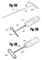
- FIGS. 8A and 8Billustrate one preferred embodiment of a gripping tool 60 designed to assist in threading attachment elements (e.g., 55 shown in FIG. 5B ) in a tissue (not shown).
- Gripping tool 60comprises a hollow handle 61 which interior may be accessed via a front opening 61 o , and a gripping element 62 capable of gripping the head section 55 a of attachment element 55 .
- Handle 61is configured to receive gripping element 62 into its interior via opening 61 o .
- Handle 61may further comprise a flange 61 a used for buffering between handle 61 and an attachment element 55 , and for assisting in releasing the attachment element 55 held by the gripping element 62 .
- gripping element 62comprises a slit 62 a capable of receiving and gripping head section 55 a of attachment element 55 .
- Gripping element 62is inserted into handle 61 such that slit 62 a may be accessed via opening 61 o to allow introducing head section 55 a of attachment element 55 thereinto.
- the practitionermay thread attachment element 55 into a tissue by holding handle 61 of gripping tool 60 and pressing and rotating attachment element 55 against the tissue.
- attachment section 55 cpenetrates into the tissue and attachment section 55 c is threaded thereinto until flanged section 61 a of handle 61 is pressed against the tissue and the grip of gripping tool 60 over head section of attachment element 55 is released.
- Handle 61may be manufactured by extrusion, for example, from a type of nylon or polyurethane, preferably from nylon 12.
- the length of handle 61may generally be in the range of 15 to 50 mm, preferably about 25 mm, and its diameter may be in the range of may generally be in the range of 5 to 8 mm.
- Gripping element 62may be manufactured by extrusion from, for example, a type of silicon, Teflon, or polyurethane, preferably from silicon.
- the length of gripping element 62may generally be in the range of 15 to 50 mm, preferably about 20 mm, and its diameter may be in the range of may generally be in the range of 3 to 7 mm.
- FIGS. 9A to 9Dschematically illustrate another preferred embodiment of a gripping tool designated by reference numeral 70 .
- the gripping and the release of said gripping over the head section of the attachment elementis carried out by means of a depressible actuator 72 laterally protruding from gripping tool 70 .
- gripping tool 70comprises a hollow housing 71 , a gripping element 73 , a hollow shaft 76 capable of receiving a proximal section of said gripping element 73 , a spring 75 disposed in the interior of housing 71 , and a depressible actuator 72 .
- Gripping element 73comprises a tapering section 73 t which tapers proximally towards a proximal slender section 73 r thereof, and a slit 73 a passing along tapering section 73 t and along a portion of slender section 73 r , wherein slit 73 a is capable of receiving the head section (e.g., 55 a ) of an attachment element.
- gripping element 73is affixed inside housing 71 by means of a pin 74 p configured to be received in two opposing holes 71 e provided in the wall of housing 71 and to pass in a bore 73 c (shown in FIG. 9D ) provided in slender section 73 r.
- Hollow shaft 76comprises a distal opening 76 a (shown in FIGS. 9B and 9D ) through which slender section 73 r and tapering section 73 t of gripping element 73 are introduce thereinto.
- the interior of hollow shaft 76comprises a tapering section 76 t which tapers proximally towards a narrow passage 76 n .
- Tapering section 76 t and narrow passage 76 n of hollow shaft 76are configured to receive slender section 73 r and tapering section 73 t , respectively, of gripping element 73 , and allow hollow shaft to slide thereover.
- Hollow shaft 76comprises two lateral grooves 76 b (shown in FIG. 9C ) passing along longitudinal portions in opposing sides thereof and adapted to allow passage of pin 74 p therethrough, such that hollow shaft can be moved distally or proximally thereover.
- hollow shaft 76is movably disposed inside housing 71 wherein spring 75 pressed against its proximal end and received in a proximal socket 76 e thereof is utilized for restoring its initial state.
- the proximal movements of hollow shaft 76are limited by tapering section 73 t of hollow shaft 76 , and its proximal movements are performed against the forces applied by spring 75 .
- hollow shaft 76comprises two lateral grooves 76 c provided at opposing sides thereof, said lateral grooves 76 c are adapted to receive lateral arms 72 c of depressible actuator 72 , said lateral arms 72 c are adapted to move up or down in grooves 76 c .
- Depressible actuator 72is movably attached to hollow housing 71 by means of pin 72 p , passing through vertical grooves 72 a provided in the upper portions of arms 72 c of depressible actuator 72 , and attached in two corresponding bores 71 b provided in the wall of hollow housing 71 . In this way, depressible actuator 72 can be moved up or down through opening 71 o provided in hollow housing 71 .
- proximal sides of lateral arms 72 c of depressible actuator 72and the proximal sides of lateral grooves 76 c , are configured with a corresponding slanted sections, such that whenever depressible actuator 72 is pressed downwardly the slanted sections of lateral arms 72 c slide along the corresponding slanted sections of lateral grooves 76 c of hollow shaft and force it to move proximally against the force applied by spring 75 .
- gripping tool 70may be used for gripping an attachment element by pressing down depressible actuator 72 for advancing gripping element 73 distally to have slit 73 a in an expanded state and allow the practitioner to introduce the head section of the attachment element thereinto. Thereafter, the practitioner releases depressible actuator which in turn retracts gripping element 73 proximally and tightens the grip over the head section. The practitioner can then thread the attachment element into the tissue by means of the gripping tool 70 , and thereafter release the grip over the head section of the anchoring element by pressing down depressible actuator 72 .
- FIGS. 10A to 10Cillustrate another implementation of a gripping element 80 of the invention having a proximal actuation.
- FIG. 10Ashows a perspective view of gripping element 80 comprising a hollow body 80 a having a distal cover 80 b fitted over a distal end section thereof, and a gripping tool 83 .
- hollow body 80 acomprises a proximal bore 80 r , an inner lumen 80 c ending in shoulders 80 d formed at a distal portion thereof which further comprises a proximally tapering section 80 e .
- Gripping element 83is made from a shaft 83 r comprising a gripping head 83 h having a distal socket 83 s .
- a distal section of gripping element 83comprises a longitudinal slit 83 a which may comprise an inner bore 83 o passing therealong for ensuring easy opening of the gripping head 83 h , said longitudinal slit 83 a splits gripping head 83 h and a distal portion of shaft 83 r into an upper and lower portions.
- gripping element 83is movably disposed inside the assembly formed by hollow body 80 a and distal cover 80 b such that a proximal section of shaft 83 r is passed through bore 80 r of hollow body 80 a , and a distal section of shaft 83 r is passed through the opening formed by shoulders 80 d .
- Gripping head 83 h of gripping tool 83tapers proximally to allow snugly introducing it into proximally tapering section 80 e of hollow body 80 a .
- the proximal end section of shaft 83 rcomprises a groove 83 g configured to receive the end of pin 80 p attached in a bore formed in the wall of hollow body 80 a . Groove 83 g and pin 80 p prevents rotations of gripping element 83 about its longitudinal axis.
- Gripping tool 70preferably has a cylindrical shape, and it may be manufactured, for example, from a type of stainless steel, plastic, or polyurethane, preferably from plastic, by means of injection.
- the length of gripping tool 70may generally be in the range of 20 to 70 mm, preferably about 40 mm, and its diameter may generally be in the range of 5 to 10 mm, preferably about 7 mm.
- the length of hollow shaftmay generally be in the range of 20 to 70 mm, preferably about 30 mm, and its diameter may generally be in the range of 3 to 10 mm, preferably about 6 mm.
- the length of tapering section 73 t of gripping tool 73may generally be in the range of 3 to 13 mm, preferably about 6 mm, and the diameter of its distal end may generally be about 3 to 10 mm.
- the length of proximal slender section 73 r of gripping tool 73may generally be in the range of 2 to 10 mm, preferably about 3 mm, and its diameter may generally be in the range of 3 to 10 mm, preferably about 5 mm.
- the length of slit 73 ais preferably about 3 to 10 mm.
- gripping head 83 his shown in a first state of gripping tool 80 , wherein gripping head 83 h is placed inside proximally tapering section 80 e .
- the upper and lower portions of gripping headare pressed one towards the other by proximally tapering section 80 e , which tightens slit 83 a .
- the practitionermay change gripping tool into its second state (not shown), wherein shaft 83 r is moved distally inside hollow body 80 a such that gripping head 83 h leaves proximally tapering section 80 e of hollow body 80 a .
- the practitionermay introduce the head section of an attachment element into slit 83 a which is typically slightly expanded in said second state.
- the practitionerAfter introducing the head section of an attachment element into slit 83 a , the practitioner releases the pressure over the pressing disk 83 p which causes gripping element to retract proximally such that gripping head 83 h is mostly returned into proximally tapering section 80 e of hollow body 80 a and slit 83 a tightens about the head section of the attachment element to provide a firm grip thereover.
- the practitionermay then thread the attachment element into a tissue by means of gripping element and thereafter release the gripping over head section of the attachment element by pressing on pressing disk 83 p and retracting gripping tool 80 proximally to release the attachment element.
- Gripping tool 80preferably has a cylindrical shape, and it may be manufactured, for example, from a type of stainless steel, plastic, or polyurethane, preferably from plastic, by means of injection.
- the length of gripping tool 80may generally be in the range of 20 to 50 mm, preferably about 35 mm, and its diameter may generally be in the range of 3 to 8 mm, preferably about 6 mm.
- the length of hollow body 80 amay generally be in the range of 10 to 30 mm, preferably about 15 mm, its outer diameter may generally be in the range of 5 to 10 mm, preferably about 7 mm, and its inner diameter may generally be in the range of 5 to 8 mm, preferably about 7 mm.
- the length of gripping element 83may generally be in the range of 30 to 70 mm, preferably about 50 mm, and the diameter of its shaft 83 r may generally be about 2 to 5 mm.
- the length of gripping head 83 hmay generally be in the range of 3 to 6 mm, preferably about 4 mm, and the diameter of its distal end may generally be about 3 to 8 mm.
- the length of slit 83 ais preferably about 3 to 8 mm.
- FIGS. 11A to 11Cillustrate yet another gripping tool implementation 90 of the invention having a rotary gripping mechanism.
- gripping tool 90comprises a main body 91 having a slidable and rotatable sleeve 92 mounted over a distal section thereof.
- FIG. 11Bshows a perspective view of main body 91 which comprises a handle portion 91 h , threaded section 91 a , and a gripping distal portion 93 comprising a longitudinal slit 93 a .
- main body 91which comprises a handle portion 91 h , threaded section 91 a , and a gripping distal portion 93 comprising a longitudinal slit 93 a .
- annular protrusion 92 eis formed on the inner wall of slidable and rotatable sleeve 92 , said annular protrusion 92 e is configured to apply pressure on a distally tapering end section 93 t of gripping distal portion 93 of main body 91 .
- Slidable and rotatable sleeve 93may further comprise threading formed in a proximal end section of its inner wall.
- This configurationpermits slidable and rotatable sleeve 92 to be advanced and retracted relative to main body 91 by rotating the same thereover.
- Such advancing and retractingalter the stated of gripping distal portion 93 between two states.
- slidable and rotatable sleeve 92is advanced distally and the pressure applied by annular protrusion 92 e over distally tapering end section 93 t of gripping distal portion 93 is released, and in turn, longitudinal slit 93 a is slightly expanded.
- the practitionermay introduce the head section of an attachment element into longitudinal slit 93 a .
- Gripping tool 90preferably has a cylindrical shape, and it may be manufactured, for example, from a type of stainless steel, plastic, or polyurethane, preferably from plastic, by means of injection.
- the length of gripping tool 90may generally be in the range of 20 to 60 mm, preferably about 35 mm, and its diameter may generally be in the range of 3 to 10 mm, preferably about 6 mm.
- the length of slidable and rotatable sleeve 92may generally be in the range of 15 to 35 mm, preferably about 20 mm, and its inner diameter may generally be in the range of 3 to 10 mm, preferably about 5 mm.
- the length of gripping distal portion 93may generally be in the range of 15 to 65 mm, preferably about 40 mm, and its diameter may generally be about 3 to 8 mm.
- the length of slit 93 ais preferably about 10 to 30 mm.
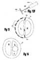
- FIGS. 12A to 12Fshow perspective views of instruments designed for guiding the practitioner in determining suitable distances between adjacent attachment elements, and between rows of such elements on the wall of the heart, by means of distance indicating arms.
- the instrument 100 shown in FIG. 12Amay be used for designating two different distances by means of two distance indicating arms, 100 h and 100 g , attached, or formed, vertical to shaft 100 r of instrument 100 .
- distance indicating arms, 100 h and 100 gare configured to give the practitioner means for determining a suitable distances between adjacent attachment elements and for determining a suitable distance between adjacent rows of attachment elements, respectively.
- instrument 100may be manufactured from a wire, strip or rod, shaped into the illustrated form. More particularly, the extremities of shaft portion 100 r of instrument 100 may be bent in a 90° angle relative to said shaft 100 r and then bent again in a 270° relative to said 100 r to form distance indicating arms 100 h and 100 g , which forms “T”-shaped structures.
- FIG. 12Billustrates a similar instrument in principle, having two distance indicating arms, 101 g and 101 h , attached, or formed, vertical to shaft 101 r , which forms “T”-shaped structures, said shaft 101 r optionally comprises handle 101 d , said optional handle is preferably placed more or less at the center of shaft 101 r .
- Instrument 101may be also manufactured from a single piece of wire, strip or rod, such that each part of instrument 101 is comprised of two sections of the wire, strip or rod.
- the instrument 102 illustrated in FIG. 12Cis designed for designating a distance for mounting an adjacent attachment element by means of a distance indicating arm 102 h , attached or formed vertical to shaft 102 r , and an acceptable tolerable deviation within which the attachment element may be mounted by means of a “U”-shaped portion 102 t provided at one end of distance indicating arm 102 h.
- Instrument 103 shown in FIG. 12Dis similar in principle, i.e., the distance for mounting an adjacent attachment element is determined by means of a distance indicating arm 103 h , attached or formed vertical to shaft 103 r , and the acceptable tolerable deviation within which the attachment element may be mounted is determined by means of a ring 103 t provided at one end of distance indicating arm 103 h .
- Handle 103 dis optionally placed at the proximal end of shaft 103 r.
- FIG. 12Eillustrates an instrument 104 wherein the distance indicating arm 104 h attached, or formed, vertical to shaft 104 r , forms an elongated loop, such that the adjacent attachment element placed therewith may be attached to the wall of the heart through said elongated loop of distance indicating arm 104 h .
- This embodimentpermits the practitioner to determine the distance of the adjacent attachment element by placing the previously installed attachment within the elongated loop of distance indicating arm 104 h near one end thereof, aligning distance indicating arm 104 h such that the other end of the elongated loop is placed at the location wherein the adjacent attachment element is to be installed, and then installing said adjacent attachment element through said elongated loop near said other end of the elongated loop.
- FIG. 12Fillustrates an instrument 105 having a distance indicating arm 105 h attached, or formed, vertical to shaft 105 r , which permits the practitioner to determine the distance to a location wherein the adjacent attachment element is to be mounted by placing the distance indicating arm 105 h between the attachment elements.
- FIG. 13illustrates another preferred embodiment of the invention for assisting ventricular heart function wherein one or more compressible elements 20 are threaded into the wall of the heart 10 .
- Compressible elements 20may be threaded into the wall of the ventricle when heart 10 is fully dilated, or alternatively when heart 10 fully contracts, in order to assist the diastolic function.
- Compressible elements 20may be manufactured by using conventional spring manufacturing techniques, wire curving processes which may be followed by a suitable thermal treatment to set mechanical characteristics and relax curving tensions.
- Compressible elements 20may be manufactured from a type of elastic metal or plastic material, such as but not limited to, Nitinol, stainless steel, silicon, or a suitable alloy, composite compound, or absorvable material, preferably from an absorvable material (e.g., PLLA, PGA, or PLA).
- compressible elements 20are made from a wire, having thickness of about 0.45 mm, turned in a shape of a spring.
- the length of compressible elements 20may generally be in the range of 2 to 15 mm, preferably about 10 mm.
- FIG. 14illustrates another preferred embodiment in which an expandable balloon 50 is used for expanding the left ventricle of the heart 10 .
- This proceduremay be used for example for mechanically expanding the left ventricle in order to ‘break’ intercellular connections and extracellular tissue of the ventricle, in order to reduce its rigidity and stiffness.
- This treatmentmay be advantageously used, for example, before mounting the elastic and attachment elements on the wall of the heart, or independently, as a standalone treatment, or in combination with other treatments.
- Balloon 50may be a conventional balloon of a balloon catheter, which may be introduced into the heart 10 using conventional procedures, as well known to those skilled in the art.
- the diameter of inflatable balloon 50should be configured according to the dimensions of the treated ventricle, for example, in the case of adult patients the diameter of fully inflated inflatable balloon 50 is typically about 50 ⁇ 20 mm.
- the elastic elements ( 13 a , 13 b , 13 c and/or 13 d ), attachment elements ( 7 , 8 , 15 a , 45 and/or 55 ), gripping tools ( 60 , 70 , 80 and/or 90 ), distance indicating instruments ( 100 , 101 , 102 , 103 , 104 and/or 105 ), and/or compressible elements ( 20 ) and expandable balloons ( 50 ), or modifications/variations thereof,may assemble a kit to be used by surgeons in heart treatment surgery.
- a typical procedure for mounting a ventricular assisting system of the inventionmay include the following steps:
- An additional such chain of alternating series of elastic elements and attachment elementsmay be mounted on the wall of the heart, preferably in parallel, by determining a distance from a previously installed chain of said elastic elements and attachment elements, preferably by means of a distance indicating instrument, and mounting said additional chain within said distance, by carrying out steps b) to f).
Landscapes
- Health & Medical Sciences (AREA)
- Life Sciences & Earth Sciences (AREA)
- Cardiology (AREA)
- Surgery (AREA)
- General Health & Medical Sciences (AREA)
- Public Health (AREA)
- Heart & Thoracic Surgery (AREA)
- Veterinary Medicine (AREA)
- Biomedical Technology (AREA)
- Animal Behavior & Ethology (AREA)
- Engineering & Computer Science (AREA)
- Molecular Biology (AREA)
- Medical Informatics (AREA)
- Nuclear Medicine, Radiotherapy & Molecular Imaging (AREA)
- Oral & Maxillofacial Surgery (AREA)
- Transplantation (AREA)
- Vascular Medicine (AREA)
- Prostheses (AREA)
- Surgical Instruments (AREA)
- External Artificial Organs (AREA)
Abstract
Description
- The present invention relates to methods and devices for improving ventricular function of the heart and, more particularly, to in-vivo methods and devices for improving diastolic function of the left ventricle of the heart.
- Heart failure (HF) is a complex clinical syndrome that can result from any structural or functional cardiac disorder that impairs the ability of the ventricle to fill with or eject blood. The cardinal manifestations of HF are dyspnea and fatigue, which may limit exercise tolerance, and fluid retention, which may lead to pulmonary congestion and peripheral edema. Heart failure is most commonly associated with impaired left ventricle (LV) systolic function. A widely used index for quantifying systolic function is ‘ejection fraction’ (EF), defined as the ratio of stroke volume to end-diastolic volume, which can be estimated using techniques such as radiocontrast, radionuclide angiography, and/or echocardiography. The normal value of EF is 0.67±0.08, which is frequently depressed in systolic heart failure even when the stroke volume is normal. A value of EF≧0.50 is commonly used as an indicator of normal systolic function. It is notable, however, that as much as 30-50% of all patients with typical symptoms of congestive heart failure have a normal or slightly reduced ejection fraction, that is, a value of EF≧0.45.
- The term diastolic heart failure (DHF) generally refers to the clinical syndrome of heart failure associated with preserved left ventricular ejection fraction, in the absence of major valvular disease.
- Primary diastolic dysfunction is typically observed in patients with hypertension and hypertrophic or restrictive cardiomyopathy, but can also occur in a variety of other clinical disorders and has a particularly high prevalence in the elderly population. Aging is associated with ‘physiologic’ diastolic dysfunction due to the increase in LV muscle mass and changes in passive elastic properties of the myocardium, hence, the concern of an increase in the incidence of diastolic dysfunction as the aging of the western world population progresses.
- To one of ordinary skill in the art, there is thus a need for, and it would be highly advantageous to have an in-vivo method and device for improving diastolic function of the left ventricle of the heart, while minimally disturbing systolic function of the heart. Moreover, there is a need for such a method and device which is biocompatible and is specially configured for compact and long-term reliable use in humans.
- Various in-vivo methods and devices for improving diastolic function of the heart are described in International patent applications Nos. PCT/IL02/00547, PCT/IL05/01014, PCT/IL04/00986, and PCT/IL04/00072, of the same assignee hereof, the descriptions of which is incorporated herein by reference. The aforementioned international patent applications describe elastic means used for improving diastolic function of the right or left ventricle of the heart by pushing and/or pulling, an inner and/or outer wall region of the ventricle during the cardiac cycle while minimally disturbing the heart function. The present invention provides modifications, improvements, accessories, and new methods and devices, for improving the diastolic function of the heart.
- It is an object of the present invention to provide methods and devices for treating systolic and diastolic dysfunctions.
- It is a further object of the present invention to provide accessories and a kit for mounting devices for treating systolic and diastolic dysfunctions of the outer surface of the wall of the heart.
- It is another object of the present invention to provide improved configurations suitable for mounting ventricular assisting means on the wall of the heart.
- Other objects and advantages of the invention will become apparent as the description proceeds.
- The present invention is directed to a system, method, kit and devices for improving diastolic function of the heart comprising elastic elements configured to be mounted on the wall of the heart by means of attachment elements, said attachment elements are adapted to be threaded into, or anchored in, the wall of the heart, and to provide an anchor for curved fasteners formed at, or attached to, extremities of the elastic elements. The system preferably comprise one or more substantially parallel rows of elastic elements mounted on the wall of the heart by means of the attachment elements, wherein each pair of adjacent elastic elements are engaged in anchoring means of a mutual attachment element.
- The term elastic element used herein to refer to an element capable of restoring its original shape after being deformed. The elastic elements of the invention may be prepared from conventional materials having known elasticity properties suitable to be used in the system and devices of the invention (e.g., Conichrome (FWM 1058)).
- In one aspect the present invention is directed to a system for improving diastolic function of the heart comprising:
- a) Elastic elements; and
- b) Attachment elements;
- wherein said elastic elements and said attachment elements are configured such that they are capable of being interconnected to form a chain formed of an alternating series of said elastic elements and said attachment elements; and wherein said attachment elements are adapted to be anchored in the wall of the heart.
- The elastic elements preferably comprise one or more torsion springs, each of which comprises two arms forming a “V” or “U” like shape. The extremities of the elastic elements are preferably bent to form curved fasteners capable of being engaged in anchoring means provided in the attachment elements.
- In one specific embodiment of the invention the elastic elements comprise torsion springs and two arms forming a “V”-like shape, wherein each of the arms comprises a curved fastener. The curved fasteners may be shaped in a form of a spiral, or a “G”-like shape, capable of being engaged in anchoring loops provided in the attachment elements. The end portion of each arm may be curved into an “S”-like shape, wherein the bottom part of the “S”-like shape is further curved to provide the spiral, or a “G”-like shape curved fastener. This configuration may be advantageously employed for engaging the curved fasteners of adjacent elastic elements at opposing sides of an anchoring loop of an attachment element, such that opposing tangential mechanical forces applied by the adjacent elastic elements over the attachment element are substantially canceled. This configuration advantageously minimizes the wear between the attachment elements and the elastic elements, substantially facilitates the implantation procedure (by attaching the elastic element to the attachment element), and efficiently prevents unintended release of the elastic elements from the attachment elements.
- Advantageously, each elastic element is comprised of a relatively straight arm and an arm having a curved section relative to the plane of the torsion spring and the relatively straight arm of the elastic element, thereby permitting the crossing of an arm having a curved section of a first elastic element with a relatively straight arm of an adjacent elastic element, while preventing physical contact therebetween.
- Advantageously, at least one of the curved fasteners of the elastic elements may comprise one or more fastening loops capable of being placed and tightened over a portion of an anchoring element. In this case the other curved fastener may be provided in a form of an anchoring (closed or semi-closed) loop, such that adjacent elastic elements may be secured to an attachment element by placing the anchoring loop provided in one arm of one of the elastic elements over the anchoring means of the attachment element and thereafter securing it thereto by tightening the one or more fastening loops provided in an arm of the adjacent elastic elements thereupon, over the anchoring means of the attachment element. A widening loop may be provided on, or near, the fastening loops for assisting in widening the fastening loops before placing them over a portion of the anchoring element. A saddle may be formed on an arm section of the elastic element near the curved fasteners for assisting in widening the fastening loops by pulling the widening ring towards the saddle by means of forceps, pliers, or any other instrument suitable for this purpose.
- In another specific embodiment of the invention the elastic elements are comprised of two “V”-shaped torsion springs having a mutual arm, which form a zigzagged shape element wherein the non-mutual arms are more or less perpendicular and wherein said non-mutual arms comprise curved fasteners configured such that the curved fasteners of two adjacent elastic elements engage opposing sides of an anchoring loop of an attachment element, thereby providing an assembly which substantially cancels opposing mechanical forces applied by adjacent elastic elements over a mutual attachment element.
- The attachment elements may be formed in a shape of a helix having an attachment section and a head section, wherein the attachment section is adapted to be threaded into a tissue and the head section comprises the anchoring means. The attachment element may further comprise a neck section, provided between the attachment section and the head section, said neck section is adapted to prevent excess threading of the attachment element into the tissue. Preferably, the neck section is formed by abruptly reducing the distances between the helix loops above the attachment section of the attachment element.
- The anchoring means of the attachment elements may be a continuation of the neck section wherein the radius of the helix loops is slightly reduced. Alternatively, the anchoring means are implemented as anchoring loops provided in the attachment element, wherein the plane of the anchoring loop is substantially parallel to, or coincides with, a concentric axis of the attachment element.
- Alternatively, the attachment elements are a type of intramural anchor having one or more barbs attached to a nail section of the intramural anchor and configured to be introduced into the tissue and prevent departure of the attachment element after it is inserted into the tissue. More particularly, the barbs are pressed along portions of the nail section of the intramural anchor during insertion into the tissue, and thereafter their state is changed into an “open” state by slightly pulling the intramural anchor proximally such that the proximal sides of the barbs are moved radially away from the nail section, while the distal side of the barbs remain attached thereto. This attachment element preferably comprises anchoring means such as the anchoring loop which plane is substantially parallel to, or coincides with, a concentric axis of the attachment element. The attachment element may further comprise stoppers provided near the anchoring means and adapted to prevent excessive insertion thereof into the tissue, and to further prevent departure of the attachment element therefrom.
- In another aspect, the present invention is directed to a device for improving diastolic function of the heart comprising an elastic element comprising one or more torsion springs, each of which comprising two arms forming a “V” or “U” like shape, wherein the extremities of said elastic element are bent to form curved fasteners capable of being engaged in an anchoring loop or ring.
- The device of the present invention is different from the devices described in WO 2004/066805 by virtue of the curved fasteners formed at the extremities of the device. This feature is highly advantageous in that it permits the practitioner to connect a series of such devices in the form of chains or rows along the heart wall. In particular, the use of substantially parallel rows of the elements has been found to be particularly advantageous for: preventing restriction of the myocardium, enabling versatility and modularity of the implantation procedure, as well as in increasing the variability of the total force supplied to the myocardium (e.g. a structure of strong medial elastic elements and relatively weaker peripheral elastic elements).
- The system may further comprise an elastic wire or stretchable cord capable of being connected to the attachment elements at the extremities of the chain formed of the alternating series of the elastic elements and the attachment elements, wherein said elastic wire or stretchable cord and said chain of elastic elements and attachment elements encircles a perimeter of the heart.
- The system may further comprise an inflatable balloon capable of being introduced into a ventricle of the heart and being inflated thereinside, and/or one or more compressible elements adapted to be threaded into the wall of the heart.
- In another aspect the invention is directed to a method for improving diastolic function of the heart, comprising:
- a) Performing a chest incision; (alternatively—mini-left thoracotomy or small incisions as in keyhole surgery approach)
- b) Attaching an attachment element to the wall of the heart, said attachment element is capable of puncturing the heart tissue and being advanced or threaded thereinto;
- c) Determining the distance from a previously attached attachment element to a location for a new such attachment element to be attached to the wall of the heart, preferably by means of a distance indicating instrument having one or more arms having suitable lengths;
- d) Attaching said new attachment element to the wall of the heart at said location;
- e) Attaching (either manually or optionally by using a gripping tool) an elastic element to anchoring means provided in said previously attached attachment elements and said new attachment element by means of attachment means provided in the extremities of said elastic element;
- f) Repeating steps c) to e) to form a chain of an alternating series of said elastic elements and said attachment elements.
- Conveniently, the attachment elements may be attached by means of a gripping tool, as follows:
- A) Gripping the anchoring means of an attachment element by said gripping tool;
- B) Puncturing the wall of the heart with a sharp tip of said attachment element and advancing/threading said attachment element thereinto until tissue resistance is encountered; and
- C) Removing said gripping tool.
- The method may further comprise mounting additional one or more such chains of alternating series of elastic elements and attachment elements on the wall of the heart, as follows:
- i) Determining a distance from a previously installed chain of said elastic elements and said attachment elements, preferably by means of a distance indicating instrument having one or more arms having suitable lengths; and
- ii) Mounting an additional chain of alternating series of elastic elements and attachment elements on the wall of the heart within said distance, by carrying out steps b) to f) above.
- Preferably, the one or more chains of alternating series of elastic elements and attachment elements are substantially parallel
- The method may further comprise attaching an elastic wire or stretchable cord to the attachment elements at the extremities of the chain formed of the alternating series of the elastic elements and the attachment elements, wherein said elastic wire or stretchable cord and said chain of elastic elements and attachment elements encircles a perimeter of the heart.
- The method may further comprise introducing an inflatable balloon into a ventricle of the heart and inflating the same thereinside. Additionally or alternatively, the method may further comprise threading one or more compressible elements into the wall of the heart.
- In yet another aspect the invention is directed to a kit of elements and instruments for mounting a ventricular function assisting system on the wall of a heart, comprising: one or more elastic elements capable of being attached to a wall of a heart, at least two attachment elements capable of being connected to anchoring means provided in said attachment elements, a gripping tool adapted to grip and hold said anchoring means, and one or more distance indicating instrument capable of being used to indicate distances between adjacent attachment elements and/or the distances between interconnected chains of said attachment and elastic elements.
- The kit may further comprise one or more compressible elements capable of being threaded into the wall of the heart, expandable balloons capable of being introduced into a ventricle of the heart and inflated thereinside, and/or an elastic wire or stretchable cord capable of being connected to the anchoring means of said attachment elements.
- The present invention is illustrated by way of example in the figures of the accompanying drawings, in which like references indicate similar elements and in which:
FIG. 1 schematically illustrates a preferred embodiment of the invention comprising a sequence of elastic elements arranged on the outer wall of the left ventricle and an elastic wire or stretchable cord mounted over the outer wall of the right ventricle;FIGS. 2A to 2D schematically illustrate embodiments of an attachment element comprising two or more barbs;FIGS. 3A and 3B schematically illustrate an embodiments of the attachment and elastic elements;FIGS. 3C and 3D schematically illustrates the attachment of the elastic elements to the attachment elements shown inFIGS. 3A and 3B ;FIGS. 4A and 4B illustrate a preferred embodiment of elastic and attachment elements and their connectivity;FIGS. 5A and 5B respectively illustrate upper and perspective views of another preferred embodiment of the elastic element and of a respective attachment element;FIG. 5C shows a perspective view of the connectivity of elastic and attachment elements shown inFIGS. 5A and 5B ;FIGS. 6A to 6C illustrate yet another preferred embodiment of the elastic element and of its connectivity to a respective attachment element, whereinFIG. 6A is an upper view of the elastic element,FIG. 6B is a perspective view of the attachment element, andFIG. 6C is a perspective view showing the connectivity of the elastic and attachment elements;FIG. 7 schematically illustrates a preferred embodiment of the attachment elements comprising drug-containing coats;FIGS. 8A and 8B respectively show perspective and exploded views of one preferred embodiment of a device for fastening attachment elements to the wall of the heart;FIGS. 9A to 9D illustrate another preferred embodiment of a device for fastening attachment elements to the wall of the heart, whereinFIG. 9A is a perspective view of the device,FIGS. 9B and 9C are perspective views of inner parts of the device, andFIG. 9D is a perspective longitudinal section view of the device;FIGS. 10A to 10C illustrate another preferred embodiment of a device for fastening attachment elements to the wall of the heart, whereinFIG. 10A is a perspective view of the device,FIG. 10B is a perspective longitudinal section view of the device, andFIG. 10C is a perspective view of inner shaft of the device;FIGS. 11A to 11C illustrate another preferred embodiment of a device for fastening attachment elements to the wall of the heart, whereinFIG. 11A is a perspective view of the device,FIG. 11B is a perspective view showing inner parts of the device, andFIG. 11C is a longitudinal section view of a rotatable element of the device;FIGS. 12A to 12F show perspective views of instruments for guiding the practitioner in determining suitable distances between adjacent attachment elements, and between rows of such elements on the wall of the heart, whereinFIGS. 12A and 12B illustrate an instrument which may be used for designating two different distances,FIG. 12C illustrates an instrument designed for designating a distance and a tolerable deviation,FIG. 12D illustrates another embodiment of the instrument shown inFIG. 12C which employs a ring for designating tolerable deviations,FIG. 12E illustrates an embodiment of the instrument comprising a closed frame for measuring distances and placing attachment elements, andFIG. 12F illustrates an embodiment of the instrument, which advantageously enables simple and accurate use and handling by the surgeon;FIG. 13 illustrates a preferred embodiment for treating ventricular dysfunctions which employs compressible elements that are threaded into the wall of the heart; andFIG. 14 illustrates a device for treating ventricular dysfunctions by means of an inflatable balloon.- The present invention provides various embodiments of ventricular function assisting devices designed for treating diastolic and/or systolic dysfunctions. The devices of the invention are designed to assist in the operation of the heart by aiding in reducing the pressures thereinside during systolic function, and aiding in increasing the pressure during diastolic function. The present invention further provides means for mounting a ventricular function assisting device of the invention on the wall of the heart of a treated subject.
FIG. 1 illustrates a preferred embodiment of the invention wherein a sequence ofelastic elements 13 are mounted over the outer wall of the left ventricle (L), and an elastic wire orstretchable cord 17 is mounted over the outer wall of the right ventricle (R), ofheart 10, by means ofattachment elements 15.Elastic elements 13 preferably have a “U” or “V” like shape which arms include detachable means at their ends for detachably connecting them to theattachment elements 15.Attachment elements 15 may be attached on, or threaded into, the wall of theheart 10 in a lined sequence having suitable gaps for mounting one or moreelastic elements 13 between each pair ofconsecutive attachment elements 15.Attachment elements 15, may be configured in a form of a screw that can be threaded into the wall of the heart, or alternatively, these elements may be manufactured in a form of a nail comprising barbs, preferably circumferential barbs along its axis, to allow placement thereof into the heart wall by pushing it into the wall of the heart, such that said barbs prevents its departure therefrom. Additionally, the distal (leading) end portion of the attachment element may be manufactured from a relatively flexible or elastic material, such as, but not limited to, Nitinol, a type of Cobalt alloy, or stainless still, formed in a helical spring-like shape, such that said distal end portion may be compressed and elongated axially within the heart wall responsive to the systolic and diastolic cycles, respectively.- Advantageously, the flexible/elastic distal (leading) end portion of the attachment element may be manufactured from an absorvable material (e.g., PLLA, PGA, PLA), and/or a suitable polymer, thus providing an attachment element having a stretchable axial length that can be stretched and compressed in response to the diastolic and systolic cycles.
- In this way the tangential forces applied by the arms of the
elastic elements 13 on theattachment elements 15 expand the heart wall in response to the increased distance effectuated between the attachment elements due to said tangential forces. This arrangement advantageously allows mounting one or more rows of linedelastic elements 13 over the wall of the heart. - In a preferred embodiment of the invention the one or more rows of lined
elastic elements 13 are arranged over the left ventricle of the heart in order to improve diastolic function. The one or more rows of linedelastic elements 13 are preferably arranged such that theattachment elements 15sat the extremities of each lined sequence are attached on, or threaded into, the wall of the heart at opposing sides of the septum (S) in order to encircle the LV and in this way attain coverage of the LV wall. In this arrangement, the elastic element advantageously stretches the septum which in turn increases the volume of the LV. - In a typical arrangement each of the rows of lined elastic elements consists of 4 to 7 (depending of the size of the treated heart)
elastic elements 13, wherein the force applied by theelastic elements 13smounted near the septum is generally about, but not limited to, 45±5 grams, and the force applied by the intermediateelastic elements 13 about (but not limited to) 70±10 grams. - Elastic wire or
stretchable cord 17 may be mounted over the outer wall of the right ventricle (R) of theheart 10 to further assist heart dilatation during diastol. Elastic wire orstretchable cord 17 may be detachably attached to theattachment elements 15sat the extremities of each lined sequence ofelastic elements 13. - If implemented as an
elastic wire 17, then the “C” shapedelastic wire 17 is preferably made from a type of elastic biocompatible metal or plastic, such as, but not limited to, stainless steel, Nitinol, suitable alloy or composite compound, preferably from stainless steel, suitable polymer, or an absorvable material (e.g., PLLA, PGA, PLA). Alternatively, the “C” shapedelastic wire 17 may be formed in a shape of a spiral wound metal wire made from one of the aforementioned metals of from a suitable alloy. In this case,elastic wire 17 mainly applies radial forces generally in the range of, but not limited to, 125±75 grams on theattachment elements 15slocated at the opposing sides of the septum (S).Elastic wire 17 connected toattachment elements 15splaced at opposing sides of the septum stretches the septum, which surface area is generally about 30% of the surface area of the heart, and thus advantageously increases the volume of the LV. Alternatively, if implemented as a stretchable cord, thenstretchable cord 17 is preferably made from a type of biocompatible rubber or elastic plastic material, such as, but not limited to, silicon or rubber, preferably from silicon or rubber. In this casestretchable cord 17 applies pressure over the wall of theheart 10 which advantageously reduces the output of the right ventricle and therefore reduces the risk for pulmonary congestion and edema. More particularly, during the systolic cyclestretchable cord 17 applies pressure on the wall of the right ventricle, and during the diastolic cyclestretchable cord 17 is stretched such that it applies pressure on the wall of the right ventricle and at the same time stretches the septum such that the volume of the LV increases. The force applied bystretchable cord 17 on the wall of the right ventricle reduces the output of the right ventricle and thus reduces the risk of pulmonary edema and the overall blood pressures in the heart. FIGS. 2A to 2C schematically illustrate a preferred embodiment of anattachment element 7 comprising two ormore barbs 7b.FIG. 2A illustratesattachment element 7 before attaching it to tissue3 (e.g., the wall of the heat).Attachment element 7 comprises anail section 7ahaving a sharp distal end capable of puncturing and penetrating a tissue, and ahead section 7c, attached or formed at the proximal end (relative to the practitioner during attachment thereof) ofattachment element 7, said head section is configured to receive and hold detachable means ofelastic elements 15.- As exemplified in
FIGS. 2A to 2C ,barbs 7bare capable of changing their state relative to nailportion 7aofattachment element 7, between an opened state (illustrated inFIGS. 2A and 2C ) and a closed state (illustrated inFIG. 2B ).FIG. 2B illustratesattachment element 7 during the attachment totissue 3, during which the sharp distal end ofnail section 7apunctures and penetrates intotissue 3, which causesbarbs 7bto change into a closed state. - With reference to
FIG. 2C , illustrating attachment element after it is attached totissue 3, after introducingnail section 7aandbarbs 7bintotissue 3,barbs 7bchange into an open state responsive to slightly pullingattachment element 7 backwardly (proximally). This mechanism anchorsattachment element 7 in its attachment location and effectively prevents its departure fromtissue 3. - Attachment element may be manufactured by wire pulling or laser cutting from a type of metallic material, such as, but not limited to, stainless steel, cobalt alloy, or nitinol, preferably from nitinol. The length of
nail section 7amay generally be in the range of 10 to 30 mm, preferably about 20 mm, and its diameter is preferably in the range of 0.1 to 1.5 mm,Barbs 7bmay be implemented by means of a doubled wire configuration attached to nailsection 7a, such that one wire of the doubled wire assembly is used for implementing a first barb and the other wire is used for implementing asecond barb 7b. The lengths ofbarbs 7bmay generally be in the range of 2 to 20 mm. FIG. 2D schematically illustrates another preferred embodiment of an attachment element8, which further comprises astopper 8dattached to nailsection 8a, near thehead section 8cof attachment element8.Stopper 8dcan be implemented by number of (e.g., 2 or 3) slanted arms (or by a conical member) connected to nailsection 8anear head section. These slanted arms, or conical member, form a skirt shape in profile which tapers toward its connection point onnail section 8a, for preventing excessive insertion ofnail section 8aintotissue 3, thereby preventing changing the state ofbarbs 8binto a closed state, after attachment totissue 3. In this way,stoppers 8dsecure attachment element8 in its attachment point, and prevent unintended departure thereof.Stopper 8dmay be manufactured from, for example, stainless steel, cobalt alloy or nitinol, preferably from nitinol. The length and angle relative to nailsection 8a, ofstopper 8dshould be configured to allow penetration of a suitable length (e.g., 1 to 10 mm) of nail section intotissue 3. For example, in one possible embodiment the length ofstopper 8dmay be about 5 to 30 mm, and its angle about 45° to 135°.FIGS. 3A to 3D illustrate one preferred embodiment of anelastic element 13aand ofattachment elements 15 suitable for mounting the same over the wall of theheart 10. As best seen inFIG. 3A ,elastic element 13ais preferably made from an elastic wire formed in a “V”-like shape having spring loop(s)30 (e.g., torsion spring) at its apex, an anchoringloop 31 at the end of one arm thereof, and afastening ring 32 at the end of its other arm.- Fastening
ring 32 may comprise one or more loops and a wideningring 34 adapted for widening the diameter of the one or more loops offastening ring 32. Fasteningring 32 may further comprise asaddle 33 formed on the arm section near its loops for assisting in widening said loops by pulling the wideningring 34 towardssaddle 33 by means of forceps, pliers, or any other instrument suitable for this purpose. - As best seen in
FIG. 3B ,attachment element 15 comprises aneck section 15aand anattachment section 15b.Attachment element 15 is preferably made from a curved wire, wherein the attachment section is curved in a shape of a helix (spring) ending in a sharp tip for facilitating puncturing the tissue and threading theattachment section 15binto the wall of the heart. Near theneck section 15aof theattachment element 15 the distances between the helix loops are reduced abruptly to form theneck section 15awherein the helix loops are tightly arranged in a slightly reduced diameter. - In this
way attachment element 15 can be threaded into the wall of the heart by rotating it about its axis and pushing the sharp end of theattachment section 15bagainst the heart wall, such that it threads into the heart wall as said sharp end penetrates the heart muscle. In this way the portion of theattachment element 15 between theneck 15aand theattachment section 15bacts as a stopper which prevents excess threading thereof. - The diameter of the loops at the end portion of the
neck section 15aof theattachment element 15 is preferably slightly enlarged in order to prevent accidental release of the fastening loop therefrom.FIG. 3D illustrates the attachment ofelastic elements 13atoattachment elements 15, wherein twoelastic elements 13aare mounted by means of attachment elements15-1,15-2 and15-3. In each attachment element (e.g.,15-2) that connects to two adjacentelastic elements 13a, the anchoringloop 31 of oneelastic element 13ais placed first over theneck section 15aof the attachment element, and then thefastening ring 32 of the adjacent attachment element is placed thereover by widening itsfastening ring 32 and fitting it over saidneck section 15a, which blocks disengagement of said anchoringloop 31. Elastic element 13amay be manufactured by conventional wire (e.g., having circular, elliptic, or rectangular/polygonal cross section) curving techniques, photo chemical etching techniques, laser cutting, or by an erosion process (e.g., using tin films), from a type of elastic metal or plastic, such as, but not limited to, Nitinol, stainless steel, silicon, or a suitable alloy, composite compound, or absorvable material (e.g., PLLA, PGA, PLA), preferably from a Cobalt alloy, having a diameter (thickness) of about 0.45 mm. The length of the arms ofelastic element 13amay generally be in the range of 20 to 30 mm, preferably about 23 mm, and the angle α therebetween is about 165±5°. The diameter of spring loop(s)30 may generally be in the range of 3.5 (for elastic elements mounted at the extremities of the lined sequence) to 5.7 mm, the diameter offastening ring 32 is preferably about 6±0.5 mm, and the diameter offastening loop 31 is preferably about 7±1 mm.- Attachment elements15-1,15-2, and15-3, may be manufactured by wire curving processes such as used in conventional spring manufacturing techniques. A suitable thermal treatment may be employed for setting desirable mechanical characteristics and relax curving tensions. Attachment elements15-1,15-2, and15-3, may be manufactured from a type of metal or plastic material, such as, but not limited to, Nitinol, stainless steel, silicon, or a suitable alloy, composite compound, or absorvable material (e.g., PLLA, PGA, PLA), preferably from a Cobalt alloy. Most preferably,
attachment elements 15 are made from a curved wire having thickness of about 0.45 mm, and made of a Cobalt alloy. - The total length of
attachment element 15 may generally be in the range of 10 to 17 mm, preferably about 15 mm. The diameter of the helix loops in theattachment section 15bmay generally be in the range of 3 to 7 mm, preferably about 5 mm, the distance between consecutive loops thereof may generally be in the range of 1 to 3 mm, preferably about 2 mm, and the length of said attachment section may generally be in the range of 6 to 10 mm, preferably about 8 mm. The diameter of theneck section 15amay generally be in the range of 2 to 4 mm, preferably about 3 mm, and its length may generally be in the range of 1 to 3 mm, preferably about 1.5 mm. FIGS. 4A and 4B illustrate another preferred embodiment of anelastic element 13b(e.g., torsion spring) and of asuitable attachment element 45 for mounting the same over the wall of theheart 10.Elastic element 13bis preferably made from an elastic wire formed in a “V”-like shape having spring loop(s)30 at its apex and “G”-shapedcurved fasteners 40 at the end of its arms.Curved fasteners 40 may have a spiral shape and they are preferably formed by bending the end sections of the arms towards spring loop(s)30, thereby formingknees 43, and thereafter bending said end sections away from said spring loop(s)30 to form a spiral shape therewith. In this way an “S”-like shape (marked bydotted line 4 inFIG. 6B ) is formed at the end of each arm, wherein the bottom portion of the “S”-like shape is further curved to form the “G”-shapedcurved fasteners 40.- In this preferred
embodiment attachment element 45 comprises ahead section 45a, aneck section 45band anattachment section 45c.Attachment element 45 is preferably made from a curved wire, wherein theattachment section 45cis curved in a helix (spring) shape ending in a sharp tip for facilitating puncturing the tissue and threadingattachment section 45cinto the wall of the heart. Near theneck section 45bof theattachment element 45 the distances between the helix loops are reduced abruptly to form theneck section 45b, which acts as a stopper to prevent excess threading. - The
head section 45ais formed in a shape of a loop through which the “G”-shaped ends i.e.,curved fasteners 40, of theelastic elements 13bcan be passed to engage the same therein.Head section 45amay be formed in any suitable geometrical shape e.g., circular, elliptic, rectangular, however, in this preferred embodiment thehead section 45ais formed in a shape of low profile rounded rectangular in order to minimize the mechanical moments exerted thereon by theelastic elements 13b. Attachment element 45 can be threaded into the wall of the heart by rotation, as was previously described herein above with reference toFIGS. 3A to 3D .FIG. 4B illustrates attachment ofelastic elements 13btoattachment elements 45, wherein twoelastic elements 13bare mounted by means of attachment elements45-1,45-2 and45-3. The “G”-shapedcurved fasteners 40 of each pair of neighboringelastic elements 13bsharing an attachment element (e.g.,45-2) are engaged in thehead section 45aof said attachment element such that their arm sections are crossed nearknees 43 and their “G”-shaped loops are pressed against the opposing sides of said head section. This configuration substantially enhances the stability of the elastic and attachment elements arrangement due to the opposing pulling forces exerted on theattachment elements 45 by the pairs of neighboringelastic elements 13b.Elastic element 13bmay be manufactured using conventional wire (e.g., having circular, elliptic, or rectangular/polygonal cross section) curving techniques, photo chemical etching techniques, laser cutting, or by an erosion process (e.g., using tin films) from a type of elastic metal or plastic, such as, but not limited to, Nitinol, stainless steel, silicon, or a suitable alloy, composite compound, or absorvable material (e.g., PLLA, PGA, or PLA), preferably from a Cobalt alloy, having a diameter (thickness) of about 0.45 mm. The length of the arms ofelastic element 13amay generally be in the range of 20 to 30 mm, preferably about 23 mm, and the angle α therebetween is about 165±5°. The diameter of spring loop(s)30 may generally be in the range of 3.5 mm (for elastic elements mounted at the extremities of the lined sequence) to 5.7 mm, and the diameter of the “G”-shapedcurved fasteners 40 is preferably about 2±1 mm.Attachment element 45 may be manufactured by a wire curving processes, such as used in conventional spring manufacturing techniques, which may be followed by a suitable thermal treatment to set mechanical characteristics and relax curving tensions.Attachment element 45 may be manufactured from a type of metal or plastic material, such as, but not limited to, Nitinol, stainless steel, silicon, or a suitable alloy, composite compound, or absorvable material (e.g., PLLA, PGA, or PLA), preferably from, a Cobalt alloy. Most preferably,attachment elements 45 are made from a curved wire having thickness of about 0.45 mm and made of a Cobalt alloy. The total length ofattachment element 45 may generally be in the range of 8 to 18 mm, preferably about 15 mm. The diameter of the helix loops in theattachment section 45cmay generally be in the range of 3 to 6 mm, preferably about 5 mm, the distance between consecutive loops thereof may generally be in the range of 1 to 3 mm, preferably about 2 mm, and the length of said attachment section may generally be in the range of 6 to 12 mm, preferably about 8 mm. The diameter of theneck section 45bmay generally be in the range of 2 to 6 mm, preferably about 5 mm, and its length may generally be in the range of 0.5 to 2 mm, preferably about 1.5 mm.FIGS. 5A to 5C illustrate yet another preferred embodiment of anelastic element 13candrespective attachment element 55 used for mounting it on the wall of the heart (not shown).Elastic element 13cis formed in a shape of a wire spring comprising two or more angled portions along its length having aspring loop 30 at each apex, for example,spring loops FIGS. 5A and 5C . The spatial width (w) of theelastic elements 13cin this preferred embodiment may be advantageously reduced since greater forces may be applied this way with shorter wire arms.Curved fasteners 50 are formed at the extremities ofelastic element 13cby curving a spiral-like loop shape at the end portions at said extremities, where said spiral-like loops are formed in opposite directions relative to asymmetry axis 57.- As shown in
FIG. 5C the spiral shapedcurved fasteners 50 of each pair of neighboringelastic elements 13csharing an attachment element (e.g.,55-2) are engaged in thehead section 55aof said attachment element such that said spiral-shaped loops are pressed against the opposing sides of thehead section 55aof said attachment element. This arrangement substantially reduces the spatial width of the device to about 2 w while also improving its stability due to the opposite pulling forces exerted by the neighboring elastic elements on the attachment elements. - As best seen in
FIG. 5B ,attachment elements 55 comprises anattachment section 55c, aneck section 55b, and ahead section 55a, having substantially similar shape and dimensions to those sections inattachment element 45 described herein above with reference toFIG. 4B . While thehead section 55aofattachment element 55 inFIG. 5B has a circular shape, it may be configured differently according to the implementation requirements, for example, it may be formed in an elliptic, rectangular, polygonal, or any other suitable geometrical shape. Elastic elements 13candattachment elements 55 may be manufactured by using the same manufacturing techniques and from the same materials aselastic elements 13bandattachment elements 45 described hereinabove. The length between an anchoringloop 50 and the neighboringspring loop 30 is generally in the range of 10 to 15 mm, preferably about 12.5 mm, the length between the spring loops (e.g.,30aand30b) is generally in the range of 20 to 30 mm, preferably about 23 mm, and the angle β between the arms ofelastic element 13cis preferably in the range of 90±15°.- The arrangement of
elastic elements 13candattachment elements 55, as shown inFIG. 5C , advantageously provides the same functionality as in the previously described embodiments of the invention while preventing friction between neighboring elastic elements as may evolve in the arrangement ofelastic elements 13bandattachment elements 45 described with reference toFIGS. 4A and 4B . FIGS. 6A to 6C illustrate a preferred embodiment of the elastic element, designated byreference numeral 13d, having an arm which at least a portion of its length is curved.Elastic element 13dis substantially similar toelastic element 13bdescribed hereinabove with reference toFIGS. 4A and 4B . As best seen in the upper view shown inFIG. 6A ,elastic element 13dcomprises afirst arm 14awhich is relatively straight, and asecond arm 14bwhich is curved relative tolongitudinal axis 38 of attachment element15d.- As illustrated in
FIG. 6C , wherein the attachment ofelastic elements 13dtoattachment elements 55 is exemplified,second arms 14bofelastic elements 13dare curved such that thestraight arm 14aof the adjacent elastic element may be passed beneath second arm to engage the head section of theattachment element 55 while maintaining agap 39 therebetween. - The attachment elements (e.g.,7,15,45 or55 ) may be further used for drug delivery by coating them with one or more layers of drug-containing coats (not illustrated).
FIG. 7 schematically illustrates such drug release (designated by arrows56) ofattachment element 55 intotissue 3. The one or more drug-containing coats are preferably adapted to provide a gradual delayed release (e.g., about 1 to 12 months) of medicaments (e.g., Sirolimus, Taxol, Batimistat, BCP671) into the tissue to which they are attached. The medicaments may be used for promoting cell growth and thereby prevent rejection of the device by the body. Alternatively, the one or more drug-containing coats may be adapted to gradually release portions of the medicaments within predetermined time periods, the duration of which may be controllably set by the practitioner e.g. by the choice of coating material, coating density, coating method etc. - Alternatively or additionally, the attachment elements may be manufactured from a hollow conduit (not shown) containing the medicaments thereinside, and having small drug release apertures (e.g., about 0.001 to 0.15 mm) capable of providing the gradual drug release needed.
FIGS. 8A and 8B illustrate one preferred embodiment of agripping tool 60 designed to assist in threading attachment elements (e.g.,55 shown inFIG. 5B ) in a tissue (not shown). Grippingtool 60 comprises ahollow handle 61 which interior may be accessed via a front opening61o, and agripping element 62 capable of gripping thehead section 55aofattachment element 55.Handle 61 is configured to receive grippingelement 62 into its interior via opening61o.Handle 61 may further comprise aflange 61aused for buffering betweenhandle 61 and anattachment element 55, and for assisting in releasing theattachment element 55 held by the grippingelement 62.- As seen in the exploded view of gripping
tool 60 shown inFIG. 8B , grippingelement 62 comprises aslit 62acapable of receiving andgripping head section 55aofattachment element 55. Grippingelement 62 is inserted intohandle 61 such that slit62amay be accessed via opening61oto allow introducinghead section 55aofattachment element 55 thereinto. After introducing;head section 55aofattachment element 55 intoslit 62aand establishing a firm grip thereover, the practitioner maythread attachment element 55 into a tissue by holdinghandle 61 of grippingtool 60 and pressing androtating attachment element 55 against the tissue. In this way the sharp end ofattachment section 55cpenetrates into the tissue andattachment section 55cis threaded thereinto untilflanged section 61aofhandle 61 is pressed against the tissue and the grip of grippingtool 60 over head section ofattachment element 55 is released. Handle 61 may be manufactured by extrusion, for example, from a type of nylon or polyurethane, preferably from nylon 12. The length ofhandle 61 may generally be in the range of 15 to 50 mm, preferably about 25 mm, and its diameter may be in the range of may generally be in the range of 5 to 8 mm. Grippingelement 62 may be manufactured by extrusion from, for example, a type of silicon, Teflon, or polyurethane, preferably from silicon. The length of grippingelement 62 may generally be in the range of 15 to 50 mm, preferably about 20 mm, and its diameter may be in the range of may generally be in the range of 3 to 7 mm.FIGS. 9A to 9D schematically illustrate another preferred embodiment of a gripping tool designated byreference numeral 70. In this preferred embodiment the gripping and the release of said gripping over the head section of the attachment element is carried out by means of adepressible actuator 72 laterally protruding from grippingtool 70. With reference to the longitudinal section view shown inFIG. 9D , grippingtool 70 comprises ahollow housing 71, a grippingelement 73, ahollow shaft 76 capable of receiving a proximal section of saidgripping element 73, aspring 75 disposed in the interior ofhousing 71, and adepressible actuator 72.- Gripping
element 73 comprises atapering section 73twhich tapers proximally towards a proximalslender section 73rthereof, and aslit 73apassing along taperingsection 73tand along a portion ofslender section 73r, wherein slit73ais capable of receiving the head section (e.g.,55a) of an attachment element. As can be seen inFIGS. 9A and 9B , grippingelement 73 is affixed insidehousing 71 by means of apin 74pconfigured to be received in two opposingholes 71eprovided in the wall ofhousing 71 and to pass in abore 73c(shown inFIG. 9D ) provided inslender section 73r. Hollow shaft 76 comprises adistal opening 76a(shown inFIGS. 9B and 9D ) through whichslender section 73rand taperingsection 73tof grippingelement 73 are introduce thereinto. The interior ofhollow shaft 76 comprises atapering section 76twhich tapers proximally towards anarrow passage 76n. Taperingsection 76tandnarrow passage 76nofhollow shaft 76 are configured to receiveslender section 73rand taperingsection 73t, respectively, of grippingelement 73, and allow hollow shaft to slide thereover.Hollow shaft 76 comprises twolateral grooves 76b(shown inFIG. 9C ) passing along longitudinal portions in opposing sides thereof and adapted to allow passage ofpin 74ptherethrough, such that hollow shaft can be moved distally or proximally thereover.- In this way
hollow shaft 76 is movably disposed insidehousing 71 whereinspring 75 pressed against its proximal end and received in aproximal socket 76ethereof is utilized for restoring its initial state. The proximal movements ofhollow shaft 76 are limited by taperingsection 73tofhollow shaft 76, and its proximal movements are performed against the forces applied byspring 75. - As shown in
FIG. 9B ,hollow shaft 76 comprises twolateral grooves 76cprovided at opposing sides thereof, saidlateral grooves 76care adapted to receivelateral arms 72cofdepressible actuator 72, saidlateral arms 72care adapted to move up or down ingrooves 76c.Depressible actuator 72 is movably attached to hollowhousing 71 by means ofpin 72p, passing throughvertical grooves 72aprovided in the upper portions ofarms 72cofdepressible actuator 72, and attached in twocorresponding bores 71bprovided in the wall ofhollow housing 71. In this way,depressible actuator 72 can be moved up or down through opening71oprovided inhollow housing 71. - The proximal sides of
lateral arms 72cofdepressible actuator 72, and the proximal sides oflateral grooves 76c, are configured with a corresponding slanted sections, such that wheneverdepressible actuator 72 is pressed downwardly the slanted sections oflateral arms 72cslide along the corresponding slanted sections oflateral grooves 76cof hollow shaft and force it to move proximally against the force applied byspring 75. During these proximal movements ofhollow shaft 76 a portion of taperingsection 73tof grippingelement 73 is moved out ofhollow shaft 76 via itsdistal opening 76a, thereby releasing the pressure applied thereover by taperingsection 76tofhollow shaft 76 and allowing slit73ato expand. - When the practitioner releases
depressible actuator 72hollow shaft 76 is moved distally due to the force applied byspring 75, which in turn forces depressible actuator to move upwardly, and a portion of taperingsection 73tof grippingelement 73 is moved back intohollow shaft 76 viadistal opening 76a. Whenever said portion of taperingsection 73tof grippingelement 73 is moved intohollow shaft 76, taperingsection 73tis pressed against taperingsection 76tofhollow shaft 76 which forces slit73ato contract. - In this
way gripping tool 70 may be used for gripping an attachment element by pressing downdepressible actuator 72 for advancinggripping element 73 distally to have slit73ain an expanded state and allow the practitioner to introduce the head section of the attachment element thereinto. Thereafter, the practitioner releases depressible actuator which in turn retracts grippingelement 73 proximally and tightens the grip over the head section. The practitioner can then thread the attachment element into the tissue by means of the grippingtool 70, and thereafter release the grip over the head section of the anchoring element by pressing downdepressible actuator 72. FIGS. 10A to 10C illustrate another implementation of agripping element 80 of the invention having a proximal actuation.FIG. 10A shows a perspective view of grippingelement 80 comprising ahollow body 80ahaving adistal cover 80bfitted over a distal end section thereof, and agripping tool 83. With reference to the longitudinal section view shown inFIG. 10B ,hollow body 80acomprises aproximal bore 80r, aninner lumen 80cending inshoulders 80dformed at a distal portion thereof which further comprises aproximally tapering section 80e. Grippingelement 83 is made from ashaft 83rcomprising a grippinghead 83hhaving adistal socket 83s. As can be seen inFIG. 10C , showing a perspective view of grippingelement 83, a distal section of grippingelement 83 comprises alongitudinal slit 83awhich may comprise an inner bore83opassing therealong for ensuring easy opening of the grippinghead 83h, saidlongitudinal slit 83asplits gripping head 83hand a distal portion ofshaft 83rinto an upper and lower portions.- As seen in
FIG. 10B , grippingelement 83 is movably disposed inside the assembly formed byhollow body 80aanddistal cover 80bsuch that a proximal section ofshaft 83ris passed throughbore 80rofhollow body 80a, and a distal section ofshaft 83ris passed through the opening formed byshoulders 80d. Grippinghead 83hof grippingtool 83 tapers proximally to allow snugly introducing it into proximally taperingsection 80eofhollow body 80a. The proximal end section ofshaft 83rcomprises agroove 83gconfigured to receive the end ofpin 80pattached in a bore formed in the wall ofhollow body 80a. Groove83gandpin 80pprevents rotations of grippingelement 83 about its longitudinal axis. - Gripping
tool 70 preferably has a cylindrical shape, and it may be manufactured, for example, from a type of stainless steel, plastic, or polyurethane, preferably from plastic, by means of injection. The length of grippingtool 70 may generally be in the range of 20 to 70 mm, preferably about 40 mm, and its diameter may generally be in the range of 5 to 10 mm, preferably about 7 mm. The length of hollow shaft may generally be in the range of 20 to 70 mm, preferably about 30 mm, and its diameter may generally be in the range of 3 to 10 mm, preferably about 6 mm. The length of taperingsection 73tof grippingtool 73 may generally be in the range of 3 to 13 mm, preferably about 6 mm, and the diameter of its distal end may generally be about 3 to 10 mm. The length of proximalslender section 73rof grippingtool 73 may generally be in the range of 2 to 10 mm, preferably about 3 mm, and its diameter may generally be in the range of 3 to 10 mm, preferably about 5 mm. The length ofslit 73ais preferably about 3 to 10 mm. - In
FIGS. 10A and 10B gripping head 83his shown in a first state of grippingtool 80, wherein grippinghead 83his placed inside proximally taperingsection 80e. In this state the upper and lower portions of gripping head are pressed one towards the other by proximally taperingsection 80e, which tightens slit83a. By pressing onpressing disk 83pattached to the proximal end of grippingelement 83 the practitioner may change gripping tool into its second state (not shown), whereinshaft 83ris moved distally insidehollow body 80asuch that grippinghead 83hleaves proximally taperingsection 80eofhollow body 80a. In this state the practitioner may introduce the head section of an attachment element intoslit 83awhich is typically slightly expanded in said second state. - After introducing the head section of an attachment element into
slit 83a, the practitioner releases the pressure over thepressing disk 83pwhich causes gripping element to retract proximally such that grippinghead 83his mostly returned into proximally taperingsection 80eofhollow body 80aand slit83atightens about the head section of the attachment element to provide a firm grip thereover. The practitioner may then thread the attachment element into a tissue by means of gripping element and thereafter release the gripping over head section of the attachment element by pressing onpressing disk 83pand retracting grippingtool 80 proximally to release the attachment element. - Gripping
tool 80 preferably has a cylindrical shape, and it may be manufactured, for example, from a type of stainless steel, plastic, or polyurethane, preferably from plastic, by means of injection. The length of grippingtool 80 may generally be in the range of 20 to 50 mm, preferably about 35 mm, and its diameter may generally be in the range of 3 to 8 mm, preferably about 6 mm. The length ofhollow body 80amay generally be in the range of 10 to 30 mm, preferably about 15 mm, its outer diameter may generally be in the range of 5 to 10 mm, preferably about 7 mm, and its inner diameter may generally be in the range of 5 to 8 mm, preferably about 7 mm. - The length of gripping
element 83 may generally be in the range of 30 to 70 mm, preferably about 50 mm, and the diameter of itsshaft 83rmay generally be about 2 to 5 mm. The length of grippinghead 83hmay generally be in the range of 3 to 6 mm, preferably about 4 mm, and the diameter of its distal end may generally be about 3 to 8 mm. The length ofslit 83ais preferably about 3 to 8 mm. FIGS. 11A to 11C illustrate yet anothergripping tool implementation 90 of the invention having a rotary gripping mechanism. As shown in the perspective view shown inFIG. 11A , grippingtool 90 comprises amain body 91 having a slidable androtatable sleeve 92 mounted over a distal section thereof.FIG. 11B shows a perspective view ofmain body 91 which comprises ahandle portion 91h, threadedsection 91a, and a grippingdistal portion 93 comprising alongitudinal slit 93a. As can be seen in the longitudinal-section view of slidable androtatable sleeve 92 shown inFIG. 11 c, anannular protrusion 92eis formed on the inner wall of slidable androtatable sleeve 92, saidannular protrusion 92eis configured to apply pressure on a distally taperingend section 93tof grippingdistal portion 93 ofmain body 91. Slidable androtatable sleeve 93 may further comprise threading formed in a proximal end section of its inner wall.- This configuration permits slidable and
rotatable sleeve 92 to be advanced and retracted relative tomain body 91 by rotating the same thereover. Such advancing and retracting alter the stated of grippingdistal portion 93 between two states. In the first state slidable androtatable sleeve 92 is advanced distally and the pressure applied byannular protrusion 92eover distally taperingend section 93tof grippingdistal portion 93 is released, and in turn, longitudinal slit93ais slightly expanded. In this state the practitioner may introduce the head section of an attachment element intolongitudinal slit 93a. When slidable androtatable sleeve 92 is retracted proximally such that the pressure applied byannular protrusion 92eover distally taperingend section 93tof grippingdistal portion 93 is restored, longitudinal slit93ais tightened and a firm grip over head section of attachment element is obtained. The practitioner may thread the attachment element into the tissue by means of grippingtool 90, and release the grip over attachment element by advancing slidable androtatable sleeve 92 distally. - Gripping
tool 90 preferably has a cylindrical shape, and it may be manufactured, for example, from a type of stainless steel, plastic, or polyurethane, preferably from plastic, by means of injection. The length of grippingtool 90 may generally be in the range of 20 to 60 mm, preferably about 35 mm, and its diameter may generally be in the range of 3 to 10 mm, preferably about 6 mm. The length of slidable androtatable sleeve 92 may generally be in the range of 15 to 35 mm, preferably about 20 mm, and its inner diameter may generally be in the range of 3 to 10 mm, preferably about 5 mm. The length of grippingdistal portion 93 may generally be in the range of 15 to 65 mm, preferably about 40 mm, and its diameter may generally be about 3 to 8 mm. The length ofslit 93ais preferably about 10 to 30 mm. FIGS. 12A to 12F show perspective views of instruments designed for guiding the practitioner in determining suitable distances between adjacent attachment elements, and between rows of such elements on the wall of the heart, by means of distance indicating arms. Theinstrument 100 shown inFIG. 12A may be used for designating two different distances by means of two distance indicating arms,100hand100g, attached, or formed, vertical toshaft 100rofinstrument 100. distance indicating arms,100hand100g, are configured to give the practitioner means for determining a suitable distances between adjacent attachment elements and for determining a suitable distance between adjacent rows of attachment elements, respectively. This is carried out by placing one end of a distance indicating arm at the location of a previously mounted attachment element, or row of such elements, and using the other end of said distance indicating arm to determine the distance to a location wherein another such attachment element, or row of such elements, is to be mounted.- As shown in
FIG. 12A ,instrument 100 may be manufactured from a wire, strip or rod, shaped into the illustrated form. More particularly, the extremities ofshaft portion 100rofinstrument 100 may be bent in a 90° angle relative to saidshaft 100rand then bent again in a 270° relative to said100rto formdistance indicating arms FIG. 12B illustrates a similar instrument in principle, having two distance indicating arms,101gand101h, attached, or formed, vertical toshaft 101r, which forms “T”-shaped structures, saidshaft 101roptionally comprises handle101d, said optional handle is preferably placed more or less at the center ofshaft 101r.Instrument 101 may be also manufactured from a single piece of wire, strip or rod, such that each part ofinstrument 101 is comprised of two sections of the wire, strip or rod.- The
instrument 102 illustrated inFIG. 12C is designed for designating a distance for mounting an adjacent attachment element by means of adistance indicating arm 102h, attached or formed vertical toshaft 102r, and an acceptable tolerable deviation within which the attachment element may be mounted by means of a “U”-shapedportion 102tprovided at one end ofdistance indicating arm 102h. Instrument 103 shown inFIG. 12D is similar in principle, i.e., the distance for mounting an adjacent attachment element is determined by means of adistance indicating arm 103h, attached or formed vertical toshaft 103r, and the acceptable tolerable deviation within which the attachment element may be mounted is determined by means of aring 103tprovided at one end ofdistance indicating arm 103h. Handle103dis optionally placed at the proximal end ofshaft 103r.FIG. 12E illustrates aninstrument 104 wherein thedistance indicating arm 104hattached, or formed, vertical toshaft 104r, forms an elongated loop, such that the adjacent attachment element placed therewith may be attached to the wall of the heart through said elongated loop ofdistance indicating arm 104h. This embodiment permits the practitioner to determine the distance of the adjacent attachment element by placing the previously installed attachment within the elongated loop ofdistance indicating arm 104hnear one end thereof, aligningdistance indicating arm 104hsuch that the other end of the elongated loop is placed at the location wherein the adjacent attachment element is to be installed, and then installing said adjacent attachment element through said elongated loop near said other end of the elongated loop.FIG. 12F illustrates aninstrument 105 having adistance indicating arm 105hattached, or formed, vertical toshaft 105r, which permits the practitioner to determine the distance to a location wherein the adjacent attachment element is to be mounted by placing thedistance indicating arm 105hbetween the attachment elements.FIG. 13 illustrates another preferred embodiment of the invention for assisting ventricular heart function wherein one or morecompressible elements 20 are threaded into the wall of theheart 10.Compressible elements 20 may be threaded into the wall of the ventricle whenheart 10 is fully dilated, or alternatively whenheart 10 fully contracts, in order to assist the diastolic function.Compressible elements 20 may be manufactured by using conventional spring manufacturing techniques, wire curving processes which may be followed by a suitable thermal treatment to set mechanical characteristics and relax curving tensions.Compressible elements 20 may be manufactured from a type of elastic metal or plastic material, such as but not limited to, Nitinol, stainless steel, silicon, or a suitable alloy, composite compound, or absorvable material, preferably from an absorvable material (e.g., PLLA, PGA, or PLA). Most preferably,compressible elements 20 are made from a wire, having thickness of about 0.45 mm, turned in a shape of a spring. The length ofcompressible elements 20 may generally be in the range of 2 to 15 mm, preferably about 10 mm.FIG. 14 illustrates another preferred embodiment in which anexpandable balloon 50 is used for expanding the left ventricle of theheart 10. This procedure may be used for example for mechanically expanding the left ventricle in order to ‘break’ intercellular connections and extracellular tissue of the ventricle, in order to reduce its rigidity and stiffness. This treatment may be advantageously used, for example, before mounting the elastic and attachment elements on the wall of the heart, or independently, as a standalone treatment, or in combination with other treatments.Balloon 50 may be a conventional balloon of a balloon catheter, which may be introduced into theheart 10 using conventional procedures, as well known to those skilled in the art. The diameter ofinflatable balloon 50 should be configured according to the dimensions of the treated ventricle, for example, in the case of adult patients the diameter of fully inflatedinflatable balloon 50 is typically about 50±20 mm.- The elastic elements (13a,13b,13cand/or13d), attachment elements (7,8,15a,45 and/or55), gripping tools (60,70,80 and/or90), distance indicating instruments (100,101,102,103,104 and/or105), and/or compressible elements (20) and expandable balloons (50), or modifications/variations thereof, may assemble a kit to be used by surgeons in heart treatment surgery. A typical procedure for mounting a ventricular assisting system of the invention may include the following steps:
- a) performing a chest incision, such as, but not limited to, thoracotomy/MIS (minimal invasive surgery—in cases wherein smaller incisions or keyhole surgery is in preference);
- b) attaching an attachment element (e.g.,7,8,15a,45 or55), preferably by means of a gripping tool (e.g.,60,70,80 and/or90), by puncturing and advancing/threading said attachment element into the wall of the heart and removing said gripping tool when tissue resistance is encountered;
- c) determining the distance to a location for a new attachment element to be attached, preferably by means of a distance indicating instruments (100,101,102,103,104 or105);
- d) attaching said new attachment element to the wall of the heart at the location determined above, preferably by means of a gripping tool, as described in step b);
- e) attaching an elastic element (13a,13b,13cand/or13d) to the attachment elements; (Optionally by gripping tool);
- f) repeating steps c) to e) to form a chain of an alternating series of said elastic elements and said attachment elements.
- An additional such chain of alternating series of elastic elements and attachment elements may be mounted on the wall of the heart, preferably in parallel, by determining a distance from a previously installed chain of said elastic elements and attachment elements, preferably by means of a distance indicating instrument, and mounting said additional chain within said distance, by carrying out steps b) to f).
- All of the abovementioned parameters are given by way of example only, and may be changed in accordance with the differing requirements of the various embodiments of the present invention. Thus, the abovementioned parameters should not be construed as limiting the scope of the present invention in any way. In addition, it is to be appreciated that the different loops, rings, cylindrical and shaft elements, and other members, described hereinabove may be constructed in different shapes (e.g. having oval, square etc. form in plan view) and sizes from those exemplified in the preceding description.
- The above examples and description have of course been provided only for the purpose of illustration, and are not intended to limit the invention in any way. As will be appreciated by the skilled person, the invention can be carried out in a great variety of ways, employing more than one technique from those described above, all without exceeding the scope of the invention.
Claims (34)
Priority Applications (1)
| Application Number | Priority Date | Filing Date | Title |
|---|---|---|---|
| US12/311,222US8382653B2 (en) | 2006-09-25 | 2007-09-25 | Method and system for improving diastolic function of the heart |
Applications Claiming Priority (3)
| Application Number | Priority Date | Filing Date | Title |
|---|---|---|---|
| US84674806P | 2006-09-25 | 2006-09-25 | |
| US12/311,222US8382653B2 (en) | 2006-09-25 | 2007-09-25 | Method and system for improving diastolic function of the heart |
| PCT/IL2007/001180WO2008038276A2 (en) | 2006-09-25 | 2007-09-25 | Method and system for improving diastolic function of the heart |
Publications (2)
| Publication Number | Publication Date |
|---|---|
| US20100022821A1true US20100022821A1 (en) | 2010-01-28 |
| US8382653B2 US8382653B2 (en) | 2013-02-26 |
Family
ID=39230669
Family Applications (1)
| Application Number | Title | Priority Date | Filing Date |
|---|---|---|---|
| US12/311,222Expired - Fee RelatedUS8382653B2 (en) | 2006-09-25 | 2007-09-25 | Method and system for improving diastolic function of the heart |
Country Status (6)
| Country | Link |
|---|---|
| US (1) | US8382653B2 (en) |
| EP (1) | EP2068768A4 (en) |
| JP (1) | JP5313902B2 (en) |
| AU (1) | AU2007301475B2 (en) |
| CA (1) | CA2663833C (en) |
| WO (1) | WO2008038276A2 (en) |
Cited By (58)
| Publication number | Priority date | Publication date | Assignee | Title |
|---|---|---|---|---|
| US20090024449A1 (en)* | 2007-05-16 | 2009-01-22 | Neurofocus Inc. | Habituation analyzer device utilizing central nervous system, autonomic nervous system and effector system measurements |
| US20090024447A1 (en)* | 2007-03-29 | 2009-01-22 | Neurofocus, Inc. | Analysis of marketing and entertainment effectiveness using central nervous system, autonomic nervous sytem, and effector data |
| US20090024475A1 (en)* | 2007-05-01 | 2009-01-22 | Neurofocus Inc. | Neuro-feedback based stimulus compression device |
| US20090030287A1 (en)* | 2007-06-06 | 2009-01-29 | Neurofocus Inc. | Incented response assessment at a point of transaction |
| US20090030303A1 (en)* | 2007-06-06 | 2009-01-29 | Neurofocus Inc. | Audience response analysis using simultaneous electroencephalography (eeg) and functional magnetic resonance imaging (fmri) |
| US20090030930A1 (en)* | 2007-05-01 | 2009-01-29 | Neurofocus Inc. | Neuro-informatics repository system |
| US20090036755A1 (en)* | 2007-07-30 | 2009-02-05 | Neurofocus, Inc. | Entity and relationship assessment and extraction using neuro-response measurements |
| US20090036756A1 (en)* | 2007-07-30 | 2009-02-05 | Neurofocus, Inc. | Neuro-response stimulus and stimulus attribute resonance estimator |
| US20090063255A1 (en)* | 2007-08-28 | 2009-03-05 | Neurofocus, Inc. | Consumer experience assessment system |
| US20090062629A1 (en)* | 2007-08-28 | 2009-03-05 | Neurofocus, Inc. | Stimulus placement system using subject neuro-response measurements |
| US20090063256A1 (en)* | 2007-08-28 | 2009-03-05 | Neurofocus, Inc. | Consumer experience portrayal effectiveness assessment system |
| US20090062681A1 (en)* | 2007-08-29 | 2009-03-05 | Neurofocus, Inc. | Content based selection and meta tagging of advertisement breaks |
| US20090082643A1 (en)* | 2007-09-20 | 2009-03-26 | Neurofocus, Inc. | Analysis of marketing and entertainment effectiveness using magnetoencephalography |
| US20090328089A1 (en)* | 2007-05-16 | 2009-12-31 | Neurofocus Inc. | Audience response measurement and tracking system |
| US20090327068A1 (en)* | 2007-05-16 | 2009-12-31 | Neurofocus Inc. | Neuro-physiology and neuro-behavioral based stimulus targeting system |
| US20100186032A1 (en)* | 2009-01-21 | 2010-07-22 | Neurofocus, Inc. | Methods and apparatus for providing alternate media for video decoders |
| US20110047121A1 (en)* | 2009-08-21 | 2011-02-24 | Neurofocus, Inc. | Analysis of the mirror neuron system for evaluation of stimulus |
| US20110046503A1 (en)* | 2009-08-24 | 2011-02-24 | Neurofocus, Inc. | Dry electrodes for electroencephalography |
| US20110046473A1 (en)* | 2009-08-20 | 2011-02-24 | Neurofocus, Inc. | Eeg triggered fmri signal acquisition |
| US20110106621A1 (en)* | 2009-10-29 | 2011-05-05 | Neurofocus, Inc. | Intracluster content management using neuro-response priming data |
| US20110105937A1 (en)* | 2009-10-29 | 2011-05-05 | Neurofocus, Inc. | Analysis of controlled and automatic attention for introduction of stimulus material |
| US20110119129A1 (en)* | 2009-11-19 | 2011-05-19 | Neurofocus, Inc. | Advertisement exchange using neuro-response data |
| US20110119124A1 (en)* | 2009-11-19 | 2011-05-19 | Neurofocus, Inc. | Multimedia advertisement exchange |
| US20110237971A1 (en)* | 2010-03-25 | 2011-09-29 | Neurofocus, Inc. | Discrete choice modeling using neuro-response data |
| US20120190918A1 (en)* | 2011-01-21 | 2012-07-26 | Abbott Cardiovascular Systems, Inc. | Apparatus and methods for supporting cardiac ischemic tissue by means of embedded structures |
| US8270814B2 (en) | 2009-01-21 | 2012-09-18 | The Nielsen Company (Us), Llc | Methods and apparatus for providing video with embedded media |
| US8392250B2 (en) | 2010-08-09 | 2013-03-05 | The Nielsen Company (Us), Llc | Neuro-response evaluated stimulus in virtual reality environments |
| US8392251B2 (en) | 2010-08-09 | 2013-03-05 | The Nielsen Company (Us), Llc | Location aware presentation of stimulus material |
| US8396744B2 (en) | 2010-08-25 | 2013-03-12 | The Nielsen Company (Us), Llc | Effective virtual reality environments for presentation of marketing materials |
| US8464288B2 (en) | 2009-01-21 | 2013-06-11 | The Nielsen Company (Us), Llc | Methods and apparatus for providing personalized media in video |
| US8655428B2 (en) | 2010-05-12 | 2014-02-18 | The Nielsen Company (Us), Llc | Neuro-response data synchronization |
| US8989835B2 (en) | 2012-08-17 | 2015-03-24 | The Nielsen Company (Us), Llc | Systems and methods to gather and analyze electroencephalographic data |
| US20160038287A1 (en)* | 2013-03-14 | 2016-02-11 | The United States Of America As Represented By The Secretary Department Of Health And Human Services | Devices and methods for treating functional tricuspid valve regurgitation |
| US9320450B2 (en) | 2013-03-14 | 2016-04-26 | The Nielsen Company (Us), Llc | Methods and apparatus to gather and analyze electroencephalographic data |
| US9364209B2 (en) | 2012-12-21 | 2016-06-14 | Abbott Cardiovascular Systems, Inc. | Articulating suturing device |
| US9414824B2 (en) | 2009-01-16 | 2016-08-16 | Abbott Vascular Inc. | Closure devices, systems, and methods |
| US9454646B2 (en) | 2010-04-19 | 2016-09-27 | The Nielsen Company (Us), Llc | Short imagery task (SIT) research method |
| US9569986B2 (en) | 2012-02-27 | 2017-02-14 | The Nielsen Company (Us), Llc | System and method for gathering and analyzing biometric user feedback for use in social media and advertising applications |
| US9585647B2 (en) | 2009-08-26 | 2017-03-07 | Abbott Laboratories | Medical device for repairing a fistula |
| US9622703B2 (en) | 2014-04-03 | 2017-04-18 | The Nielsen Company (Us), Llc | Methods and apparatus to gather and analyze electroencephalographic data |
| US9936250B2 (en) | 2015-05-19 | 2018-04-03 | The Nielsen Company (Us), Llc | Methods and apparatus to adjust content presented to an individual |
| US9962144B2 (en) | 2006-06-28 | 2018-05-08 | Abbott Laboratories | Vessel closure device |
| US10111664B2 (en) | 2000-01-05 | 2018-10-30 | Integrated Vascular Systems, Inc. | Closure system and methods of use |
| US10201340B2 (en) | 2002-02-21 | 2019-02-12 | Integrated Vascular Systems, Inc. | Sheath apparatus and methods for delivering a closure device |
| US10245013B2 (en) | 2000-12-07 | 2019-04-02 | Integrated Vascular Systems, Inc. | Closure device and methods for making and using them |
| US10299928B2 (en)* | 2015-01-05 | 2019-05-28 | David Alon | Heart ventricle remodeling |
| US10506974B2 (en) | 2016-03-14 | 2019-12-17 | The Nielsen Company (Us), Llc | Headsets and electrodes for gathering electroencephalographic data |
| US10898330B2 (en) | 2017-03-28 | 2021-01-26 | Edwards Lifesciences Corporation | Positioning, deploying, and retrieving implantable devices |
| US10963895B2 (en) | 2007-09-20 | 2021-03-30 | Nielsen Consumer Llc | Personalized content delivery using neuro-response priming data |
| US10973662B2 (en)* | 2016-05-16 | 2021-04-13 | Elixir Medical Corporation | Methods and devices for heart valve repair |
| US10987164B2 (en)* | 2010-10-19 | 2021-04-27 | Michael D. Laufer | Methods and devices for diastolic assist |
| WO2022099152A1 (en)* | 2020-11-09 | 2022-05-12 | Elliott Jolley | Systems and methods for providing an orthodontic spring |
| US11481788B2 (en) | 2009-10-29 | 2022-10-25 | Nielsen Consumer Llc | Generating ratings predictions using neuro-response data |
| US20220370201A1 (en)* | 2008-07-01 | 2022-11-24 | Maquet Cardiovascular Llc | Epicardial Clip |
| US11690720B2 (en) | 2014-09-28 | 2023-07-04 | Edwards Lifesciences Corporation | Systems and methods for treating cardiac dysfunction |
| US11704681B2 (en) | 2009-03-24 | 2023-07-18 | Nielsen Consumer Llc | Neurological profiles for market matching and stimulus presentation |
| WO2024238743A1 (en)* | 2023-05-17 | 2024-11-21 | Edwards Lifesciences Corporation | Systems for epicardial tissue distension solutions |
| US12410844B2 (en) | 2020-11-09 | 2025-09-09 | Elliott Jolley | Systems and methods for providing advanced springs |
Families Citing this family (34)
| Publication number | Priority date | Publication date | Assignee | Title |
|---|---|---|---|---|
| US8529430B2 (en) | 2002-08-01 | 2013-09-10 | Cardiokinetix, Inc. | Therapeutic methods and devices following myocardial infarction |
| US9694121B2 (en) | 1999-08-09 | 2017-07-04 | Cardiokinetix, Inc. | Systems and methods for improving cardiac function |
| US10307147B2 (en) | 1999-08-09 | 2019-06-04 | Edwards Lifesciences Corporation | System for improving cardiac function by sealing a partitioning membrane within a ventricle |
| US8500795B2 (en) | 1999-08-09 | 2013-08-06 | Cardiokinetix, Inc. | Retrievable devices for improving cardiac function |
| US8388672B2 (en) | 1999-08-09 | 2013-03-05 | Cardiokinetix, Inc. | System for improving cardiac function by sealing a partitioning membrane within a ventricle |
| US9332992B2 (en) | 2004-08-05 | 2016-05-10 | Cardiokinetix, Inc. | Method for making a laminar ventricular partitioning device |
| US9332993B2 (en) | 2004-08-05 | 2016-05-10 | Cardiokinetix, Inc. | Devices and methods for delivering an endocardial device |
| US9078660B2 (en) | 2000-08-09 | 2015-07-14 | Cardiokinetix, Inc. | Devices and methods for delivering an endocardial device |
| US10064696B2 (en) | 2000-08-09 | 2018-09-04 | Edwards Lifesciences Corporation | Devices and methods for delivering an endocardial device |
| EP2520252A1 (en) | 2008-02-11 | 2012-11-07 | Corassist Cardiovascular Ltd. | Ventricular function assisting devices and methods of use thereof |
| FR2930137B1 (en)* | 2008-04-18 | 2010-04-23 | Corevalve Inc | TREATMENT EQUIPMENT FOR A CARDIAC VALVE, IN PARTICULAR A MITRAL VALVE. |
| EP2344070B1 (en) | 2008-10-20 | 2017-08-09 | Corassist Cardiovascular Ltd. | Ventricular function assisting device and apparatus for implanting it |
| DE102008064221B4 (en)* | 2008-12-22 | 2016-03-17 | Koki Technik Transmission Systems Gmbh | shift fork |
| US20100274266A1 (en)* | 2009-04-22 | 2010-10-28 | Ofir Rimer | Rotary tack |
| US8790242B2 (en) | 2009-10-26 | 2014-07-29 | Cardiokinetix, Inc. | Ventricular volume reduction |
| GB2495499B (en)* | 2011-10-11 | 2019-02-06 | Hs Products Ltd | Hybrid spring |
| US10004600B2 (en) | 2012-05-02 | 2018-06-26 | Renzo Cecere | Device for soft tissue support and method for anchoring |
| GB2506104B (en) | 2012-08-10 | 2018-12-12 | Hs Products Ltd | Resilient unit with different major surfaces |
| US10543088B2 (en) | 2012-09-14 | 2020-01-28 | Boston Scientific Scimed, Inc. | Mitral valve inversion prostheses |
| US10849755B2 (en) | 2012-09-14 | 2020-12-01 | Boston Scientific Scimed, Inc. | Mitral valve inversion prostheses |
| US9180005B1 (en) | 2014-07-17 | 2015-11-10 | Millipede, Inc. | Adjustable endolumenal mitral valve ring |
| EP3200846B1 (en) | 2014-10-01 | 2020-01-15 | Heartware, Inc. | Backup controller system with updating |
| US9848983B2 (en) | 2015-02-13 | 2017-12-26 | Millipede, Inc. | Valve replacement using rotational anchors |
| CN107847323B (en) | 2015-06-01 | 2020-04-24 | 爱德华兹生命科学公司 | Heart valve repair device configured for percutaneous delivery |
| US10335275B2 (en) | 2015-09-29 | 2019-07-02 | Millipede, Inc. | Methods for delivery of heart valve devices using intravascular ultrasound imaging |
| CN111329541B (en) | 2015-11-17 | 2023-09-19 | 波士顿科学国际有限公司 | Implantable devices and delivery systems for reshaping cardiac annulus |
| US10548731B2 (en) | 2017-02-10 | 2020-02-04 | Boston Scientific Scimed, Inc. | Implantable device and delivery system for reshaping a heart valve annulus |
| CN110603007A (en) | 2017-03-27 | 2019-12-20 | 维维泰生物医药有限公司 | Devices and methods for transcatheter mitral and tricuspid valve repair |
| GB201708635D0 (en) | 2017-05-31 | 2017-07-12 | Hs Products Ltd | Pocketed spring unit and method manufacture |
| GB201708639D0 (en) | 2017-05-31 | 2017-07-12 | Hs Products Ltd | Transportation Apparatus and method |
| CA3078412C (en)* | 2017-10-19 | 2022-05-24 | Shanghai Hanyu Medical Technology Co., Ltd | Valve clamping device |
| US11413146B2 (en) | 2018-10-03 | 2022-08-16 | Edwards Lifesciences Corporation | Spring and coil devices for papillary muscle approximation and ventricle remodeling |
| US11413147B2 (en) | 2018-10-03 | 2022-08-16 | Edwards Lifesciences Corporation | Ventricular remodeling using coil devices |
| CN110279945B (en)* | 2019-07-10 | 2022-12-20 | 潘登 | Implantable cardiac pacemaker |
Citations (12)
| Publication number | Priority date | Publication date | Assignee | Title |
|---|---|---|---|---|
| US3508332A (en)* | 1967-04-17 | 1970-04-28 | Armstrong M M | Formable orthodontic hook |
| US3618214A (en)* | 1970-05-04 | 1971-11-09 | Armstrong M M | Coiled wire spring appliances for use in orthodontics |
| US5363522A (en)* | 1994-03-02 | 1994-11-15 | Hickory Springs Manufacturing Company | Spring assembly and perimeter support spring therefor |
| US20010025171A1 (en)* | 1998-07-29 | 2001-09-27 | Myocor, Inc. | Transventricular implant tools and devices |
| US20020045800A1 (en)* | 2000-03-10 | 2002-04-18 | Lilip Lau | Expandable cardiac harness for treating congestive heart failure |
| US20020188170A1 (en)* | 2001-04-27 | 2002-12-12 | Santamore William P. | Prevention of myocardial infarction induced ventricular expansion and remodeling |
| US20040002626A1 (en)* | 2001-07-16 | 2004-01-01 | Yair Feld | In-vivo method and device for improving diastolic function of the left ventricle |
| US20040116992A1 (en)* | 2002-09-26 | 2004-06-17 | Wardle John L. | Cardiovascular anchoring device and method of deploying same |
| US20040153101A1 (en)* | 1994-08-05 | 2004-08-05 | Lee Bolduc | Surgical helical fastener with applicator |
| US20040267279A1 (en)* | 2003-04-24 | 2004-12-30 | Simon Casutt | Distance measuring instrument for pedicle screws |
| US20060161040A1 (en)* | 1997-01-02 | 2006-07-20 | Myocor, Inc. | Methods and devices for improving cardiac function in hearts |
| US20060199995A1 (en)* | 2005-03-02 | 2006-09-07 | Venkataramana Vijay | Percutaneous cardiac ventricular geometry restoration device and treatment for heart failure |
Family Cites Families (7)
| Publication number | Priority date | Publication date | Assignee | Title |
|---|---|---|---|---|
| EP1333780A2 (en)* | 2000-10-19 | 2003-08-13 | St. Jude Medical, Inc. | Driver tool with multiple drive gear layers for heart prosthesis fasteners |
| CA2513726C (en) | 2003-01-27 | 2014-08-12 | Corassist Cardiovascular Ltd. | In vivo device for improving diastolic ventricular function |
| JP4691017B2 (en)* | 2003-03-18 | 2011-06-01 | セント ジュード メディカル インコーポレイテッド | Body tissue remodeling method and apparatus |
| WO2005041745A2 (en) | 2003-10-31 | 2005-05-12 | Corassist Cardiovascular Ltd. | In vivo device for improving diastolic ventricular function |
| GB0408907D0 (en)* | 2004-04-22 | 2004-05-26 | Trw Lucasvarity Electric Steer | Improved steering column assembly |
| US20060004249A1 (en)* | 2004-06-30 | 2006-01-05 | Ethicon Incorporated | Systems and methods for sizing cardiac assist device |
| WO2006033107A2 (en) | 2004-09-22 | 2006-03-30 | Corassist Cardiovascular Ltd. | In vivo device for assisting and improving diastolic ventricular function |
- 2007
- 2007-09-25EPEP07827154.1Apatent/EP2068768A4/ennot_activeWithdrawn
- 2007-09-25AUAU2007301475Apatent/AU2007301475B2/ennot_activeCeased
- 2007-09-25CACA2663833Apatent/CA2663833C/ennot_activeExpired - Fee Related
- 2007-09-25WOPCT/IL2007/001180patent/WO2008038276A2/enactiveApplication Filing
- 2007-09-25USUS12/311,222patent/US8382653B2/ennot_activeExpired - Fee Related
- 2007-09-25JPJP2009528875Apatent/JP5313902B2/ennot_activeExpired - Fee Related
Patent Citations (13)
| Publication number | Priority date | Publication date | Assignee | Title |
|---|---|---|---|---|
| US3508332A (en)* | 1967-04-17 | 1970-04-28 | Armstrong M M | Formable orthodontic hook |
| US3618214A (en)* | 1970-05-04 | 1971-11-09 | Armstrong M M | Coiled wire spring appliances for use in orthodontics |
| US5363522A (en)* | 1994-03-02 | 1994-11-15 | Hickory Springs Manufacturing Company | Spring assembly and perimeter support spring therefor |
| US20040153101A1 (en)* | 1994-08-05 | 2004-08-05 | Lee Bolduc | Surgical helical fastener with applicator |
| US20060161040A1 (en)* | 1997-01-02 | 2006-07-20 | Myocor, Inc. | Methods and devices for improving cardiac function in hearts |
| US20010025171A1 (en)* | 1998-07-29 | 2001-09-27 | Myocor, Inc. | Transventricular implant tools and devices |
| US20030032979A1 (en)* | 1998-07-29 | 2003-02-13 | Myocor, Inc. | Transventricular implant tools and devices |
| US20020045800A1 (en)* | 2000-03-10 | 2002-04-18 | Lilip Lau | Expandable cardiac harness for treating congestive heart failure |
| US20020188170A1 (en)* | 2001-04-27 | 2002-12-12 | Santamore William P. | Prevention of myocardial infarction induced ventricular expansion and remodeling |
| US20040002626A1 (en)* | 2001-07-16 | 2004-01-01 | Yair Feld | In-vivo method and device for improving diastolic function of the left ventricle |
| US20040116992A1 (en)* | 2002-09-26 | 2004-06-17 | Wardle John L. | Cardiovascular anchoring device and method of deploying same |
| US20040267279A1 (en)* | 2003-04-24 | 2004-12-30 | Simon Casutt | Distance measuring instrument for pedicle screws |
| US20060199995A1 (en)* | 2005-03-02 | 2006-09-07 | Venkataramana Vijay | Percutaneous cardiac ventricular geometry restoration device and treatment for heart failure |
Cited By (124)
| Publication number | Priority date | Publication date | Assignee | Title |
|---|---|---|---|---|
| US10111664B2 (en) | 2000-01-05 | 2018-10-30 | Integrated Vascular Systems, Inc. | Closure system and methods of use |
| US10245013B2 (en) | 2000-12-07 | 2019-04-02 | Integrated Vascular Systems, Inc. | Closure device and methods for making and using them |
| US10201340B2 (en) | 2002-02-21 | 2019-02-12 | Integrated Vascular Systems, Inc. | Sheath apparatus and methods for delivering a closure device |
| US9962144B2 (en) | 2006-06-28 | 2018-05-08 | Abbott Laboratories | Vessel closure device |
| US10679241B2 (en) | 2007-03-29 | 2020-06-09 | The Nielsen Company (Us), Llc | Analysis of marketing and entertainment effectiveness using central nervous system, autonomic nervous system, and effector data |
| US20090024447A1 (en)* | 2007-03-29 | 2009-01-22 | Neurofocus, Inc. | Analysis of marketing and entertainment effectiveness using central nervous system, autonomic nervous sytem, and effector data |
| US11250465B2 (en) | 2007-03-29 | 2022-02-15 | Nielsen Consumer Llc | Analysis of marketing and entertainment effectiveness using central nervous system, autonomic nervous sytem, and effector data |
| US8484081B2 (en) | 2007-03-29 | 2013-07-09 | The Nielsen Company (Us), Llc | Analysis of marketing and entertainment effectiveness using central nervous system, autonomic nervous system, and effector data |
| US11790393B2 (en) | 2007-03-29 | 2023-10-17 | Nielsen Consumer Llc | Analysis of marketing and entertainment effectiveness using central nervous system, autonomic nervous system, and effector data |
| US8473345B2 (en) | 2007-03-29 | 2013-06-25 | The Nielsen Company (Us), Llc | Protocol generator and presenter device for analysis of marketing and entertainment effectiveness |
| US20090024475A1 (en)* | 2007-05-01 | 2009-01-22 | Neurofocus Inc. | Neuro-feedback based stimulus compression device |
| US20090030930A1 (en)* | 2007-05-01 | 2009-01-29 | Neurofocus Inc. | Neuro-informatics repository system |
| US8386312B2 (en) | 2007-05-01 | 2013-02-26 | The Nielsen Company (Us), Llc | Neuro-informatics repository system |
| US9886981B2 (en) | 2007-05-01 | 2018-02-06 | The Nielsen Company (Us), Llc | Neuro-feedback based stimulus compression device |
| US20090327068A1 (en)* | 2007-05-16 | 2009-12-31 | Neurofocus Inc. | Neuro-physiology and neuro-behavioral based stimulus targeting system |
| US8392253B2 (en) | 2007-05-16 | 2013-03-05 | The Nielsen Company (Us), Llc | Neuro-physiology and neuro-behavioral based stimulus targeting system |
| US20090328089A1 (en)* | 2007-05-16 | 2009-12-31 | Neurofocus Inc. | Audience response measurement and tracking system |
| US11049134B2 (en) | 2007-05-16 | 2021-06-29 | Nielsen Consumer Llc | Neuro-physiology and neuro-behavioral based stimulus targeting system |
| US10580031B2 (en) | 2007-05-16 | 2020-03-03 | The Nielsen Company (Us), Llc | Neuro-physiology and neuro-behavioral based stimulus targeting system |
| US20090024449A1 (en)* | 2007-05-16 | 2009-01-22 | Neurofocus Inc. | Habituation analyzer device utilizing central nervous system, autonomic nervous system and effector system measurements |
| US8494905B2 (en) | 2007-06-06 | 2013-07-23 | The Nielsen Company (Us), Llc | Audience response analysis using simultaneous electroencephalography (EEG) and functional magnetic resonance imaging (fMRI) |
| US20090030287A1 (en)* | 2007-06-06 | 2009-01-29 | Neurofocus Inc. | Incented response assessment at a point of transaction |
| US20090030303A1 (en)* | 2007-06-06 | 2009-01-29 | Neurofocus Inc. | Audience response analysis using simultaneous electroencephalography (eeg) and functional magnetic resonance imaging (fmri) |
| US20090036756A1 (en)* | 2007-07-30 | 2009-02-05 | Neurofocus, Inc. | Neuro-response stimulus and stimulus attribute resonance estimator |
| US10733625B2 (en) | 2007-07-30 | 2020-08-04 | The Nielsen Company (Us), Llc | Neuro-response stimulus and stimulus attribute resonance estimator |
| US20090036755A1 (en)* | 2007-07-30 | 2009-02-05 | Neurofocus, Inc. | Entity and relationship assessment and extraction using neuro-response measurements |
| US11763340B2 (en) | 2007-07-30 | 2023-09-19 | Nielsen Consumer Llc | Neuro-response stimulus and stimulus attribute resonance estimator |
| US11244345B2 (en) | 2007-07-30 | 2022-02-08 | Nielsen Consumer Llc | Neuro-response stimulus and stimulus attribute resonance estimator |
| US8533042B2 (en) | 2007-07-30 | 2013-09-10 | The Nielsen Company (Us), Llc | Neuro-response stimulus and stimulus attribute resonance estimator |
| US20090063256A1 (en)* | 2007-08-28 | 2009-03-05 | Neurofocus, Inc. | Consumer experience portrayal effectiveness assessment system |
| US8635105B2 (en) | 2007-08-28 | 2014-01-21 | The Nielsen Company (Us), Llc | Consumer experience portrayal effectiveness assessment system |
| US20090063255A1 (en)* | 2007-08-28 | 2009-03-05 | Neurofocus, Inc. | Consumer experience assessment system |
| US10937051B2 (en) | 2007-08-28 | 2021-03-02 | The Nielsen Company (Us), Llc | Stimulus placement system using subject neuro-response measurements |
| US20090062629A1 (en)* | 2007-08-28 | 2009-03-05 | Neurofocus, Inc. | Stimulus placement system using subject neuro-response measurements |
| US8392254B2 (en) | 2007-08-28 | 2013-03-05 | The Nielsen Company (Us), Llc | Consumer experience assessment system |
| US10127572B2 (en) | 2007-08-28 | 2018-11-13 | The Nielsen Company, (US), LLC | Stimulus placement system using subject neuro-response measurements |
| US8386313B2 (en) | 2007-08-28 | 2013-02-26 | The Nielsen Company (Us), Llc | Stimulus placement system using subject neuro-response measurements |
| US11488198B2 (en) | 2007-08-28 | 2022-11-01 | Nielsen Consumer Llc | Stimulus placement system using subject neuro-response measurements |
| US11023920B2 (en) | 2007-08-29 | 2021-06-01 | Nielsen Consumer Llc | Content based selection and meta tagging of advertisement breaks |
| US20090062681A1 (en)* | 2007-08-29 | 2009-03-05 | Neurofocus, Inc. | Content based selection and meta tagging of advertisement breaks |
| US11610223B2 (en) | 2007-08-29 | 2023-03-21 | Nielsen Consumer Llc | Content based selection and meta tagging of advertisement breaks |
| US10140628B2 (en) | 2007-08-29 | 2018-11-27 | The Nielsen Company, (US), LLC | Content based selection and meta tagging of advertisement breaks |
| US8392255B2 (en) | 2007-08-29 | 2013-03-05 | The Nielsen Company (Us), Llc | Content based selection and meta tagging of advertisement breaks |
| US10963895B2 (en) | 2007-09-20 | 2021-03-30 | Nielsen Consumer Llc | Personalized content delivery using neuro-response priming data |
| US8494610B2 (en) | 2007-09-20 | 2013-07-23 | The Nielsen Company (Us), Llc | Analysis of marketing and entertainment effectiveness using magnetoencephalography |
| US20090082643A1 (en)* | 2007-09-20 | 2009-03-26 | Neurofocus, Inc. | Analysis of marketing and entertainment effectiveness using magnetoencephalography |
| US20220370201A1 (en)* | 2008-07-01 | 2022-11-24 | Maquet Cardiovascular Llc | Epicardial Clip |
| US9414824B2 (en) | 2009-01-16 | 2016-08-16 | Abbott Vascular Inc. | Closure devices, systems, and methods |
| US8955010B2 (en) | 2009-01-21 | 2015-02-10 | The Nielsen Company (Us), Llc | Methods and apparatus for providing personalized media in video |
| US8464288B2 (en) | 2009-01-21 | 2013-06-11 | The Nielsen Company (Us), Llc | Methods and apparatus for providing personalized media in video |
| US9826284B2 (en) | 2009-01-21 | 2017-11-21 | The Nielsen Company (Us), Llc | Methods and apparatus for providing alternate media for video decoders |
| US8977110B2 (en) | 2009-01-21 | 2015-03-10 | The Nielsen Company (Us), Llc | Methods and apparatus for providing video with embedded media |
| US9357240B2 (en) | 2009-01-21 | 2016-05-31 | The Nielsen Company (Us), Llc | Methods and apparatus for providing alternate media for video decoders |
| US8270814B2 (en) | 2009-01-21 | 2012-09-18 | The Nielsen Company (Us), Llc | Methods and apparatus for providing video with embedded media |
| US20100186032A1 (en)* | 2009-01-21 | 2010-07-22 | Neurofocus, Inc. | Methods and apparatus for providing alternate media for video decoders |
| US11704681B2 (en) | 2009-03-24 | 2023-07-18 | Nielsen Consumer Llc | Neurological profiles for market matching and stimulus presentation |
| US20110046473A1 (en)* | 2009-08-20 | 2011-02-24 | Neurofocus, Inc. | Eeg triggered fmri signal acquisition |
| US20110047121A1 (en)* | 2009-08-21 | 2011-02-24 | Neurofocus, Inc. | Analysis of the mirror neuron system for evaluation of stimulus |
| US8655437B2 (en) | 2009-08-21 | 2014-02-18 | The Nielsen Company (Us), Llc | Analysis of the mirror neuron system for evaluation of stimulus |
| US10987015B2 (en) | 2009-08-24 | 2021-04-27 | Nielsen Consumer Llc | Dry electrodes for electroencephalography |
| US20110046503A1 (en)* | 2009-08-24 | 2011-02-24 | Neurofocus, Inc. | Dry electrodes for electroencephalography |
| US9585647B2 (en) | 2009-08-26 | 2017-03-07 | Abbott Laboratories | Medical device for repairing a fistula |
| US20110106621A1 (en)* | 2009-10-29 | 2011-05-05 | Neurofocus, Inc. | Intracluster content management using neuro-response priming data |
| US20110105937A1 (en)* | 2009-10-29 | 2011-05-05 | Neurofocus, Inc. | Analysis of controlled and automatic attention for introduction of stimulus material |
| US8762202B2 (en) | 2009-10-29 | 2014-06-24 | The Nielson Company (Us), Llc | Intracluster content management using neuro-response priming data |
| US11669858B2 (en) | 2009-10-29 | 2023-06-06 | Nielsen Consumer Llc | Analysis of controlled and automatic attention for introduction of stimulus material |
| US11481788B2 (en) | 2009-10-29 | 2022-10-25 | Nielsen Consumer Llc | Generating ratings predictions using neuro-response data |
| US9560984B2 (en) | 2009-10-29 | 2017-02-07 | The Nielsen Company (Us), Llc | Analysis of controlled and automatic attention for introduction of stimulus material |
| US11170400B2 (en) | 2009-10-29 | 2021-11-09 | Nielsen Consumer Llc | Analysis of controlled and automatic attention for introduction of stimulus material |
| US10269036B2 (en) | 2009-10-29 | 2019-04-23 | The Nielsen Company (Us), Llc | Analysis of controlled and automatic attention for introduction of stimulus material |
| US8209224B2 (en) | 2009-10-29 | 2012-06-26 | The Nielsen Company (Us), Llc | Intracluster content management using neuro-response priming data |
| US10068248B2 (en) | 2009-10-29 | 2018-09-04 | The Nielsen Company (Us), Llc | Analysis of controlled and automatic attention for introduction of stimulus material |
| US20110119124A1 (en)* | 2009-11-19 | 2011-05-19 | Neurofocus, Inc. | Multimedia advertisement exchange |
| US20110119129A1 (en)* | 2009-11-19 | 2011-05-19 | Neurofocus, Inc. | Advertisement exchange using neuro-response data |
| US8335715B2 (en) | 2009-11-19 | 2012-12-18 | The Nielsen Company (Us), Llc. | Advertisement exchange using neuro-response data |
| US8335716B2 (en) | 2009-11-19 | 2012-12-18 | The Nielsen Company (Us), Llc. | Multimedia advertisement exchange |
| US20110237971A1 (en)* | 2010-03-25 | 2011-09-29 | Neurofocus, Inc. | Discrete choice modeling using neuro-response data |
| US11200964B2 (en) | 2010-04-19 | 2021-12-14 | Nielsen Consumer Llc | Short imagery task (SIT) research method |
| US10248195B2 (en) | 2010-04-19 | 2019-04-02 | The Nielsen Company (Us), Llc. | Short imagery task (SIT) research method |
| US9454646B2 (en) | 2010-04-19 | 2016-09-27 | The Nielsen Company (Us), Llc | Short imagery task (SIT) research method |
| US8655428B2 (en) | 2010-05-12 | 2014-02-18 | The Nielsen Company (Us), Llc | Neuro-response data synchronization |
| US9336535B2 (en) | 2010-05-12 | 2016-05-10 | The Nielsen Company (Us), Llc | Neuro-response data synchronization |
| US8392250B2 (en) | 2010-08-09 | 2013-03-05 | The Nielsen Company (Us), Llc | Neuro-response evaluated stimulus in virtual reality environments |
| US8392251B2 (en) | 2010-08-09 | 2013-03-05 | The Nielsen Company (Us), Llc | Location aware presentation of stimulus material |
| US8548852B2 (en) | 2010-08-25 | 2013-10-01 | The Nielsen Company (Us), Llc | Effective virtual reality environments for presentation of marketing materials |
| US8396744B2 (en) | 2010-08-25 | 2013-03-12 | The Nielsen Company (Us), Llc | Effective virtual reality environments for presentation of marketing materials |
| US10987164B2 (en)* | 2010-10-19 | 2021-04-27 | Michael D. Laufer | Methods and devices for diastolic assist |
| US20120190918A1 (en)* | 2011-01-21 | 2012-07-26 | Abbott Cardiovascular Systems, Inc. | Apparatus and methods for supporting cardiac ischemic tissue by means of embedded structures |
| US9569986B2 (en) | 2012-02-27 | 2017-02-14 | The Nielsen Company (Us), Llc | System and method for gathering and analyzing biometric user feedback for use in social media and advertising applications |
| US10881348B2 (en) | 2012-02-27 | 2021-01-05 | The Nielsen Company (Us), Llc | System and method for gathering and analyzing biometric user feedback for use in social media and advertising applications |
| US9215978B2 (en) | 2012-08-17 | 2015-12-22 | The Nielsen Company (Us), Llc | Systems and methods to gather and analyze electroencephalographic data |
| US9907482B2 (en) | 2012-08-17 | 2018-03-06 | The Nielsen Company (Us), Llc | Systems and methods to gather and analyze electroencephalographic data |
| US11980469B2 (en) | 2012-08-17 | 2024-05-14 | Nielsen Company | Systems and methods to gather and analyze electroencephalographic data |
| US8989835B2 (en) | 2012-08-17 | 2015-03-24 | The Nielsen Company (Us), Llc | Systems and methods to gather and analyze electroencephalographic data |
| US9060671B2 (en) | 2012-08-17 | 2015-06-23 | The Nielsen Company (Us), Llc | Systems and methods to gather and analyze electroencephalographic data |
| US10842403B2 (en) | 2012-08-17 | 2020-11-24 | The Nielsen Company (Us), Llc | Systems and methods to gather and analyze electroencephalographic data |
| US10779745B2 (en) | 2012-08-17 | 2020-09-22 | The Nielsen Company (Us), Llc | Systems and methods to gather and analyze electroencephalographic data |
| US9364209B2 (en) | 2012-12-21 | 2016-06-14 | Abbott Cardiovascular Systems, Inc. | Articulating suturing device |
| US11076807B2 (en) | 2013-03-14 | 2021-08-03 | Nielsen Consumer Llc | Methods and apparatus to gather and analyze electroencephalographic data |
| US20160038287A1 (en)* | 2013-03-14 | 2016-02-11 | The United States Of America As Represented By The Secretary Department Of Health And Human Services | Devices and methods for treating functional tricuspid valve regurgitation |
| US9987135B2 (en)* | 2013-03-14 | 2018-06-05 | The United States Of America, As Represented By The Secretary, Department Of Health And Human Services | Devices and methods for treating functional tricuspid valve regurgitation |
| US9320450B2 (en) | 2013-03-14 | 2016-04-26 | The Nielsen Company (Us), Llc | Methods and apparatus to gather and analyze electroencephalographic data |
| US9668694B2 (en) | 2013-03-14 | 2017-06-06 | The Nielsen Company (Us), Llc | Methods and apparatus to gather and analyze electroencephalographic data |
| US11141108B2 (en) | 2014-04-03 | 2021-10-12 | Nielsen Consumer Llc | Methods and apparatus to gather and analyze electroencephalographic data |
| US9622703B2 (en) | 2014-04-03 | 2017-04-18 | The Nielsen Company (Us), Llc | Methods and apparatus to gather and analyze electroencephalographic data |
| US9622702B2 (en) | 2014-04-03 | 2017-04-18 | The Nielsen Company (Us), Llc | Methods and apparatus to gather and analyze electroencephalographic data |
| US12310853B2 (en) | 2014-09-28 | 2025-05-27 | Edwards Lifesciences Corporation | Systems and methods for treating cardiac dysfunction |
| US11690720B2 (en) | 2014-09-28 | 2023-07-04 | Edwards Lifesciences Corporation | Systems and methods for treating cardiac dysfunction |
| US10299928B2 (en)* | 2015-01-05 | 2019-05-28 | David Alon | Heart ventricle remodeling |
| US9936250B2 (en) | 2015-05-19 | 2018-04-03 | The Nielsen Company (Us), Llc | Methods and apparatus to adjust content presented to an individual |
| US11290779B2 (en) | 2015-05-19 | 2022-03-29 | Nielsen Consumer Llc | Methods and apparatus to adjust content presented to an individual |
| US10771844B2 (en) | 2015-05-19 | 2020-09-08 | The Nielsen Company (Us), Llc | Methods and apparatus to adjust content presented to an individual |
| US10925538B2 (en) | 2016-03-14 | 2021-02-23 | The Nielsen Company (Us), Llc | Headsets and electrodes for gathering electroencephalographic data |
| US10506974B2 (en) | 2016-03-14 | 2019-12-17 | The Nielsen Company (Us), Llc | Headsets and electrodes for gathering electroencephalographic data |
| US11607169B2 (en) | 2016-03-14 | 2023-03-21 | Nielsen Consumer Llc | Headsets and electrodes for gathering electroencephalographic data |
| US12167920B2 (en) | 2016-03-14 | 2024-12-17 | Nielsen Consumer Llc | Headsets and electrodes for gathering electroencepalographic data |
| US10568572B2 (en) | 2016-03-14 | 2020-02-25 | The Nielsen Company (Us), Llc | Headsets and electrodes for gathering electroencephalographic data |
| US11191656B2 (en) | 2016-05-16 | 2021-12-07 | Elixir Medical Corporation | Methods and devices for heart valve repair |
| US10973662B2 (en)* | 2016-05-16 | 2021-04-13 | Elixir Medical Corporation | Methods and devices for heart valve repair |
| US10898330B2 (en) | 2017-03-28 | 2021-01-26 | Edwards Lifesciences Corporation | Positioning, deploying, and retrieving implantable devices |
| WO2022099152A1 (en)* | 2020-11-09 | 2022-05-12 | Elliott Jolley | Systems and methods for providing an orthodontic spring |
| US12410844B2 (en) | 2020-11-09 | 2025-09-09 | Elliott Jolley | Systems and methods for providing advanced springs |
| US12409017B2 (en) | 2020-11-09 | 2025-09-09 | Elliott Jolley | Systems and methods for providing an orthodontic spring |
| WO2024238743A1 (en)* | 2023-05-17 | 2024-11-21 | Edwards Lifesciences Corporation | Systems for epicardial tissue distension solutions |
Also Published As
| Publication number | Publication date |
|---|---|
| AU2007301475A1 (en) | 2008-04-03 |
| AU2007301475B2 (en) | 2013-04-18 |
| WO2008038276A3 (en) | 2010-09-16 |
| US8382653B2 (en) | 2013-02-26 |
| WO2008038276A2 (en) | 2008-04-03 |
| JP5313902B2 (en) | 2013-10-09 |
| CA2663833C (en) | 2014-10-07 |
| CA2663833A1 (en) | 2008-04-03 |
| EP2068768A4 (en) | 2014-01-08 |
| JP2010504137A (en) | 2010-02-12 |
| EP2068768A2 (en) | 2009-06-17 |
Similar Documents
| Publication | Publication Date | Title |
|---|---|---|
| US8382653B2 (en) | Method and system for improving diastolic function of the heart | |
| US12310853B2 (en) | Systems and methods for treating cardiac dysfunction | |
| EP3668450B1 (en) | Dome structure for improved left ventricle function | |
| US8500622B2 (en) | Ventricular function assisting device and a method and apparatus for implanting it | |
| CN107920813B (en) | Tissue clamping device and related method | |
| US8523755B2 (en) | Ventricular function assisting devices and methods of use thereof | |
| EP3169247B1 (en) | Mechanical retraction via tethering for lung volume reduction | |
| JP2019513032A (en) | Cardiac contraction stimulation system and method | |
| JP2020520297A (en) | Articulated prosthesis and associated capture device for tricuspid or mitral valve | |
| US20080015407A1 (en) | Device and Method for Modifying the Shape of a Body Organ | |
| JP2018533446A (en) | Implantable device and delivery system for reshaping a heart valve ring | |
| JP2019516518A (en) | Posterior mitral valve cusp | |
| WO2012158186A1 (en) | Percutaneous mitral annulus mini-plication | |
| JP2010005422A (en) | Delivery device and method for heart valve repair | |
| EP2967857B1 (en) | Devices for treating functional tricuspid valve regurgitation | |
| JP2022534251A (en) | Frame release mechanism of valve repair device | |
| JP2012101094A (en) | Delivery device and method for heart valve repair |
Legal Events
| Date | Code | Title | Description |
|---|---|---|---|
| AS | Assignment | Owner name:CORASSIST CARDIOVASCULAR LTD., ISRAEL Free format text:ASSIGNMENT OF ASSIGNORS INTEREST;ASSIGNORS:DUBI, SHAY;KOVALSKY, IGOR;FELD, YAIR;AND OTHERS;REEL/FRAME:023239/0230;SIGNING DATES FROM 20090306 TO 20090524 Owner name:CORASSIST CARDIOVASCULAR LTD., ISRAEL Free format text:ASSIGNMENT OF ASSIGNORS INTEREST;ASSIGNORS:DUBI, SHAY;KOVALSKY, IGOR;FELD, YAIR;AND OTHERS;SIGNING DATES FROM 20090306 TO 20090524;REEL/FRAME:023239/0230 | |
| STCF | Information on status: patent grant | Free format text:PATENTED CASE | |
| FPAY | Fee payment | Year of fee payment:4 | |
| FEPP | Fee payment procedure | Free format text:MAINTENANCE FEE REMINDER MAILED (ORIGINAL EVENT CODE: REM.); ENTITY STATUS OF PATENT OWNER: SMALL ENTITY | |
| FEPP | Fee payment procedure | Free format text:7.5 YR SURCHARGE - LATE PMT W/IN 6 MO, SMALL ENTITY (ORIGINAL EVENT CODE: M2555); ENTITY STATUS OF PATENT OWNER: SMALL ENTITY | |
| MAFP | Maintenance fee payment | Free format text:PAYMENT OF MAINTENANCE FEE, 8TH YR, SMALL ENTITY (ORIGINAL EVENT CODE: M2552); ENTITY STATUS OF PATENT OWNER: SMALL ENTITY Year of fee payment:8 | |
| FEPP | Fee payment procedure | Free format text:MAINTENANCE FEE REMINDER MAILED (ORIGINAL EVENT CODE: REM.); ENTITY STATUS OF PATENT OWNER: SMALL ENTITY | |
| LAPS | Lapse for failure to pay maintenance fees | Free format text:PATENT EXPIRED FOR FAILURE TO PAY MAINTENANCE FEES (ORIGINAL EVENT CODE: EXP.); ENTITY STATUS OF PATENT OWNER: SMALL ENTITY | |
| STCH | Information on status: patent discontinuation | Free format text:PATENT EXPIRED DUE TO NONPAYMENT OF MAINTENANCE FEES UNDER 37 CFR 1.362 | |
| FP | Lapsed due to failure to pay maintenance fee | Effective date:20250226 |