US20090147412A1 - Transformer inrush current detector - Google Patents
Transformer inrush current detectorDownload PDFInfo
- Publication number
- US20090147412A1 US20090147412A1US11/999,813US99981307AUS2009147412A1US 20090147412 A1US20090147412 A1US 20090147412A1US 99981307 AUS99981307 AUS 99981307AUS 2009147412 A1US2009147412 A1US 2009147412A1
- Authority
- US
- United States
- Prior art keywords
- current
- differential
- samples
- time derivative
- inrush
- Prior art date
- Legal status (The legal status is an assumption and is not a legal conclusion. Google has not performed a legal analysis and makes no representation as to the accuracy of the status listed.)
- Granted
Links
- 238000000034methodMethods0.000claimsabstractdescription35
- 238000005070samplingMethods0.000claimsabstractdescription27
- 230000004044responseEffects0.000claimsabstractdescription13
- 230000000903blocking effectEffects0.000claimsabstractdescription12
- 238000001514detection methodMethods0.000claimsabstractdescription8
- 230000004913activationEffects0.000claims5
- 230000035945sensitivityEffects0.000abstractdescription3
- 239000004020conductorSubstances0.000description24
- 230000008569processEffects0.000description14
- 230000008859changeEffects0.000description12
- 238000010586diagramMethods0.000description5
- 238000002955isolationMethods0.000description4
- 238000004804windingMethods0.000description4
- XEEYBQQBJWHFJM-UHFFFAOYSA-NIronChemical group[Fe]XEEYBQQBJWHFJM-UHFFFAOYSA-N0.000description3
- 230000007246mechanismEffects0.000description3
- 230000003044adaptive effectEffects0.000description2
- 238000007796conventional methodMethods0.000description2
- 230000000737periodic effectEffects0.000description2
- 230000006641stabilisationEffects0.000description2
- 238000011105stabilizationMethods0.000description2
- 230000001052transient effectEffects0.000description2
- 238000013459approachMethods0.000description1
- 238000012937correctionMethods0.000description1
- 238000013016dampingMethods0.000description1
- 230000003111delayed effectEffects0.000description1
- 230000001419dependent effectEffects0.000description1
- 230000004907fluxEffects0.000description1
- 230000001939inductive effectEffects0.000description1
- 230000010354integrationEffects0.000description1
- 238000005259measurementMethods0.000description1
- 230000010363phase shiftEffects0.000description1
- 238000012545processingMethods0.000description1
- 230000001681protective effectEffects0.000description1
- 238000012552reviewMethods0.000description1
- 230000001960triggered effectEffects0.000description1
Images


Classifications
- H—ELECTRICITY
- H02—GENERATION; CONVERSION OR DISTRIBUTION OF ELECTRIC POWER
- H02H—EMERGENCY PROTECTIVE CIRCUIT ARRANGEMENTS
- H02H7/00—Emergency protective circuit arrangements specially adapted for specific types of electric machines or apparatus or for sectionalised protection of cable or line systems, and effecting automatic switching in the event of an undesired change from normal working conditions
- H02H7/04—Emergency protective circuit arrangements specially adapted for specific types of electric machines or apparatus or for sectionalised protection of cable or line systems, and effecting automatic switching in the event of an undesired change from normal working conditions for transformers
- H02H7/045—Differential protection of transformers
- H02H7/0455—Differential protection of transformers taking into account saturation of current transformers
- H—ELECTRICITY
- H02—GENERATION; CONVERSION OR DISTRIBUTION OF ELECTRIC POWER
- H02H—EMERGENCY PROTECTIVE CIRCUIT ARRANGEMENTS
- H02H3/00—Emergency protective circuit arrangements for automatic disconnection directly responsive to an undesired change from normal electric working condition with or without subsequent reconnection ; integrated protection
- H02H3/26—Emergency protective circuit arrangements for automatic disconnection directly responsive to an undesired change from normal electric working condition with or without subsequent reconnection ; integrated protection responsive to difference between voltages or between currents; responsive to phase angle between voltages or between currents
- H02H3/28—Emergency protective circuit arrangements for automatic disconnection directly responsive to an undesired change from normal electric working condition with or without subsequent reconnection ; integrated protection responsive to difference between voltages or between currents; responsive to phase angle between voltages or between currents involving comparison of the voltage or current values at two spaced portions of a single system, e.g. at opposite ends of one line, at input and output of apparatus
- H—ELECTRICITY
- H02—GENERATION; CONVERSION OR DISTRIBUTION OF ELECTRIC POWER
- H02H—EMERGENCY PROTECTIVE CIRCUIT ARRANGEMENTS
- H02H1/00—Details of emergency protective circuit arrangements
- H02H1/04—Arrangements for preventing response to transient abnormal conditions, e.g. to lightning or to short duration over voltage or oscillations; Damping the influence of DC component by short circuits in AC networks
- H02H1/043—Arrangements for preventing response to transient abnormal conditions, e.g. to lightning or to short duration over voltage or oscillations; Damping the influence of DC component by short circuits in AC networks to inrush currents
- H—ELECTRICITY
- H02—GENERATION; CONVERSION OR DISTRIBUTION OF ELECTRIC POWER
- H02H—EMERGENCY PROTECTIVE CIRCUIT ARRANGEMENTS
- H02H3/00—Emergency protective circuit arrangements for automatic disconnection directly responsive to an undesired change from normal electric working condition with or without subsequent reconnection ; integrated protection
- H02H3/44—Emergency protective circuit arrangements for automatic disconnection directly responsive to an undesired change from normal electric working condition with or without subsequent reconnection ; integrated protection responsive to the rate of change of electrical quantities
Definitions
- the present inventionrelates to a differential protection system for power transformers and more specifically to a power transformer protection system using Rogowski coils for current sensing and for detecting inrush current of the power transformer.
- a power transformeris used to step up, or step down, a voltage. That is, the output voltage is the input voltage times a step factor.
- the step factoris generally called the transformer ratio and is also known as turns ratio. This ratio is defined as the ratio of the primary and secondary voltages for a two winding transformer.
- a transformer that steps up voltagewill step down current while a transformer that steps down voltage will step up current. Since power equals voltage times current, power is the same on both sides of the transformer, ignoring transformer losses.
- the current entering a power transformershould be equal to the current leaving the power transformer. A difference between the current entering the transformer and the current leaving the transformer can indicate a fault within the transformer where current is being diverted into the transformer rather than passing through the transformer.
- Differential protection of power transformersis a technique that compares the current entering the transformer with the current leaving the transformer.
- One side of a transformeris the primary while the other side is the secondary.
- the side where power entersis the primary.
- a differential protection systemsenses the current at the primary side and also senses the current at the secondary side. The area between the current sensors is called the protection zone.
- the differential protection systemdetermines if there is an excessive difference, aside from the scaling factor, between the two current sensors. If the difference exceeds the relay setting (differential threshold), a fault within the protection zone is likely, and a protection relay initiates operation of a circuit breaker or other device to isolate the power transformer.
- the difference between the primary current and the secondary current that is required to trip the differential protection system and to cause the protection relay to operatecan be called the differential threshold of the differential protection system.
- a differential protection system with a lower differential thresholdmay be more sensitive, but can be falsely triggered by non fault events.
- current transformersare used in a differential protection system to sense the primary current and the secondary current.
- Current transformerstypically have iron cores and may saturate. Transformer core saturation occurs when more magnetic flux is induced within the transformer than can be handled by the core. When a transformer core saturates, it may lose its inductive characteristics allowing currents in the transformer windings to temporarily spike to extremely high levels.
- Unequal saturation between the current transformer sensing the primary current and the current transformer sensing the secondary currentis an example of a false triggering event as no fault is involved.
- the differential threshold of a protection systemmay be set as a percentage of the current passing through the transformer.
- This differential threshold settinggenerally is provided by adding restraint components to stabilize the protection relay. Relay stabilization improves performance since high through currents will require a higher differential current to operate the relay.
- This qualitygenerally is characterized by the slope of the relay. The slope is given by a sloped line that relates the current passing through the transformer with the differential threshold setting. The line is sloped because a higher through-current implies setting a higher differential threshold. Such a relationship may be illustrated using an upward sloping line when plotted on a graph with through-current on the horizontal axis and differential current threshold on the vertical axis. In systems where the relay is controlled digitally, multiple slopes may be utilized to avoid inappropriately operating the protection relay in conditions involving severe current transformer saturation caused by high fault currents.
- Inrush currentis the input current drawn by a device when power is initially applied to the device. Inrush current is a startup transient. When a power transformer is first energized, an inrush current much larger than the rated transformer current can flow for up to tens of seconds. That is, when a transformer is first powered on, a higher current must flow into the transformer to establish the magnetic fields within the transformer core. Inrush current flows at the energizing side of the transformer, while there may be little or no current flow at the other side of transformer. In a networked application, the energizing side of the transformer may be the primary side or the secondary side. Since inrush current generally flows on only one side of the transformer, the current differential between the primary and secondary sides of the transformer easily can exceed the differential threshold of the differential protection system and can cause the protection relay to isolate the power transformer even though an actual fault does not exist.
- inrush currentis detected by extracting the second harmonic component from the inrush current using mathematical algorithms. This technique typically involves applying filters to the current measurements to isolate the second harmonic component which is a portion of the current signal at about twice the operating frequency of the power system.
- filtershave been developed to extract this second harmonic information. Varying response characteristics at this second harmonic for different transformers, as well as the complexity of the related filter designs, often complicate such traditional approaches.
- the present inventionrelates to a differential protection system for power transformers using Rogowski coils as current sensors.
- a Rogowski coilcan comprise a helical, or quasi-helical, coil of wire with the lead from one end returning through the center of the coil to the other end, so that both leads are at one end of the coil.
- the coilthen may be formed around a straight conductor where the current in the straight conductor is to be measured.
- the voltage that is induced in the Rogowski coilis proportional to the rate of change of current in the straight conductor. This rate of change of current also is called the first time derivative of the current, or di/dt, or change in current per change in time.
- the output of the Rogowski coilcan be used to represent di/dt where “i” is the current in the straight conductor being measured.
- the output of a Rogowski coilcan be connected to an electronic integrator circuit to provide a signal that is proportional to the sensed current.
- Rogowski coilscan provide low inductance and excellent response to fast-changing currents since they have air cores rather than an iron core. Without an iron core to saturate, a Rogowski coil can be highly linear even in high current applications. Furthermore, having reduced saturation concerns, the Rogowski coil protection system may employ a single slope response with increased sensitivity. Also, the geometry of a Rogowski coil may provide a current sensor that is significantly immune to electromagnetic interference.
- the present inventionfurther relates to methods for detecting inrush current for a power transformer. Using the output of the Rogowski coils, which is proportional to the derivative of the sensed current, periodic low di/dt periods in the sensed current are used to detect power transformer inrush conditions. Another aspect of the present invention relates to discrete time sampling techniques for identifying the low di/dt portions within the sensed current. Effective detection of power transformer inrush conditions can enable blocking of the protection system during inrush where the differential current may exceed the differential threshold without the presence of an actual fault.
- transformer protection systemsin this summary is for illustration only. Various aspects of the present invention may be more clearly understood and appreciated from a review of the following detailed description of the disclosed embodiments and by reference to the drawings and the claims that follow. Moreover, other aspects, systems, methods, features, advantages, and objects of the present invention will become apparent to one with skill in the art upon examination of the following drawings and detailed description. It is intended that all such aspects, systems, methods, features, advantages, and objects are included within this description, are within the scope of the present invention, and are protected by the accompanying claims.
- FIG. 1is a circuit diagram illustrating a schematic representation of a transformer and a differential protection system using Rogowski coil current sensors according to one exemplary embodiment of the present invention.
- FIG. 2is a graph illustrating relay slopes used in differential protection systems for transformers according to a conventional method and according to one exemplary embodiment of the present invention.
- FIG. 3is a plot illustrating the inrush current of a power transformer and a corresponding plot illustrating the output of a Rogowski coil according to one exemplary embodiment of the present invention.
- FIG. 4is a plot of a sampled Rogowski coil output while sensing the inrush current of a power transformer according to one exemplary embodiment of the present invention.
- FIG. 5is a logical flow diagram of a process for detecting transformer inrush current in a differential protection system using Rogowski coils according to one exemplary embodiment of the present invention.
- the present inventionrelates to a differential protection system for power transformers using Rogowski coils as current sensors and to methods for detecting inrush current for a power transformer.
- Discrete time sampling techniquescan be used for identifying the low di/dt portions within the sensed current. Effective detection of power transformer inrush conditions can enable blocking of the protection system during inrush where the differential current may exceed the differential threshold without the presence of an actual fault.
- FIG. 1the figure is a circuit diagram illustrating a transformer 110 and a differential protection system 100 using Rogowski coil current sensors 130 A, 130 B according to one exemplary embodiment of the present invention.
- the power transformer 110may comprise a primary transformer coil 110 A and a secondary transformer coil 110 B.
- Alternating current (AC)may be conducted into, or out of, the primary transformer coil 110 A through primary conductor 120 A.
- Alternating currentmay be conducted into, or out of, the secondary transformer coil 110 B through primary conductor 120 B.
- the current flowing in the primary conductor 120 Amay be sensed by a primary side Rogowski coil 130 A.
- the current flowing in the secondary conductor 120 Bmay be sensed by a secondary side Rogowski coil 130 B.
- the portion of the system 100 between the primary side Rogowski coil 130 A and the secondary side Rogowski coil 130 Bincludes the transformer 110 .
- This portion of the system between the sensor coils 130 A, 130 Bcan be referred to as the protection zone of the differential protection system 100 .
- the output of the primary side Rogowski coil 130 Ais the primary side sense signal 140 A.
- the primary side sense signal 140 Amay be proportional to the first time derivative of the primary side current flowing in the primary conductor 120 A.
- the output of the secondary side Rogowski coil 130 Bis the secondary side sense signal 140 B.
- the secondary side sense signal 140 Bmay be proportional to the first time derivative of the secondary side current flowing in the secondary conductor 120 B.
- a differential protection controller 150can process the primary side sense signal 140 A and the secondary side sense signal 140 B to detect transformer inrush currents and to control the operation of a protection relay.
- the protection controller 150may be referred to as the relay.
- the protection relay(not illustrated in FIG. 1 ) can isolate the transformer 110 when a fault condition occurs based upon an output of the protection controller 150 . This isolation can be provided by a circuit breaker or other device operated by the protection relay.
- a large difference between the current flowing in the primary conductor 120 A and the current flowing in the secondary conductor 120 Bmay occur even though a fault is not present within the zone of protection.
- the differential protection controller 150can block the unnecessary operation of the protection relay and associated circuit breakers during inrush.
- the differential protection controller 150may be operable to carry out a process for detecting power transformer inrush current similar to process 500 detailed with respect to FIG. 5 .
- the differential protection controller 150may comprise a microprocessor, a microcontroller, a digital signal processor, an analog signal processing circuit, an application specific integrated circuit (ASIC), a field programmable gate array (FPGA), a system on chip (SOC), a complex programmable gate array (CPLD), digital logic, combinational logic, sequential logic, any other computing mechanism, logic mechanism, state machine, or any combination thereof.
- the differential protection controller 150may comprise software, firmware, hardware, or any combination thereof.
- the protection system 100may be operated with polyphase power systems. For example, two-phase, three-phase, or other such power transformers may be protected. In a three-phase system, three circuit conductors carry three alternating currents of the same frequency where, using one conductor as a reference, the other two currents are delayed in time by one-third and two-thirds of a cycle, respectively.
- a three-phase power transformermay have three primary windings and three secondary windings.
- the sensors 130 of the differential protection system 100may be employed on any one of the three phases, any two of the phases, or all three of the phases.
- the protection relaymay isolate all three phases of the transformer using circuit breaker or other device operation.
- An indication of an inrush condition on one phasemay be used to block any of the phase protection elements in the protection relay. Such operation can be referred to as cross-phase blocking or phase dependent blocking.
- the protection relay, or relaysmay isolate each of the three phases of the transformer individually.
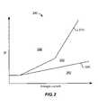
- FIG. 2the figure is a graph 200 illustrating relay slopes used in differential protection systems for transformers according to a conventional method and according to one exemplary embodiment of the present invention.
- the horizontal axis of the graph 200represents the current flowing through the transformer from the primary conductor 120 A to the secondary conductor 120 B.
- the vertical axis of the graphrepresents the differential current ( ⁇ I).
- the differential currentis the difference between the current flowing in the primary conductor 120 A and the current flowing in the secondary conductor 120 B.
- comparing, or subtracting, primary and secondary currentscan involve first adjusting one or both of the primary or secondary currents for the transformer ratio and/or the sensor ratio.
- the differential threshold of a protection systemmay be set as a percentage of the current passing through the transformer.
- This differential threshold settingcan be made by adding restraint components to stabilize the protection relay. Relay stabilization improves performance since high through currents will require a higher differential current to operate the relay. This quality generally is characterized by the slope of the relay.
- the slope of a relaymay be illustrated as a sloped line that relates the current passing through the transformer with the differential threshold setting.
- the lineis sloped because a higher through-current implies setting a higher differential threshold.
- Such a relationshipmay be illustrated using an upward sloping line when plotted on a graph with through-current on the horizontal axis and differential current threshold on the vertical axis.
- multiple slopesmay be utilized to avoid inappropriately operating the protection relay in conditions involving severe current transformer saturation caused by high fault currents.
- Curve 210 of the graph 200illustrates an example double slope relay response that may be seen in traditional systems using iron-core current transformers to sense current. Multiple slopes may be utilized to avoid inappropriately operating the protection relay in conditions involving severe current transformer saturation. Such current transformer saturation may be caused by high fault currents.
- the increased slope of curve 210 at higher through currentsrepresents an increase in the differential threshold current.
- Such an increase in the differential threshold currentmeans that, at higher through-currents, a greater difference between the primary and secondary is required to trip the protection relay.
- the sensitivity of the protection system 100may need to be reduced to avoid false positive operation that may be induced by increased core saturation in the sensing transformers at the higher currents.
- a protection system using Rogowski coils 130 A, 130 B to sense currentaccording to an exemplary embodiment of the invention, saturation of the sensing mechanism may be substantially eliminated.
- the sensing coils 130 A, 130 Bmay deliver a more accurate representation of the current flowing in the primary conductor 120 A and the current flowing in the secondary conductor 120 B even at high through current operation of the transformer 110 .
- the system 100 using Rogowski coils 130 A, 130 Bcan use a more sensitive relay slope such as that illustrated by curve 220 of the graph 200 .
- Region 260 of the graph 200represents the blocking zone where operation of the protection relay is blocked.
- Region 240 of the graph 200represents the operating zone where the operation of the protection relay is not blocked.
- the protection relaymay operate to isolate the power transformer as the differential current exceeds the differential threshold representing a fault condition.
- Region 250 of the graph 200represents a zone where the traditional current transformer based systems would block operation of the relay, but where Rogowski coil based systems 100 according to an exemplary embodiment of the invention may allow the protection relay to operate. This added operation zone 250 for such Rogowski coil based systems may provide a more sensitive protective differential protection solution.
- FIG. 3the figure is a plot 310 illustrating the inrush current of a power transformer 110 and a corresponding plot 320 illustrating the output of a Rogowski coil 130 A, 130 B according to one exemplary embodiment of the present invention.
- Plot 310illustrates the inrush current of a power transformer 110 .
- Inrush currentis the input to the power transformer 110 when power is initially applied to the transformer 110 .
- Inrush currentis a startup transient.
- an inrush currentmuch larger than the rated transformer current can flow for up to tens of seconds or more.
- the transformer 110may be energized from the primary side or from the secondary side. Since inrush current may generally flow only to one side of the transformer, the inrush current plot 310 may be related to either one of the sense transformers 130 A, 130 B depending upon which side of the transformer is being energized.
- Plot 320illustrates the output of a Rogowski coil 130 A, 130 B sensing the inrush current illustrated in plot 310 .
- the voltage that is induced in the Rogowski coilis proportional to the rate of change of current being sensed. This rate of change of current is also called the first time derivative of the current, or di/dt, or change in current per change in time.
- the substantially flat portions 330 of each cycle of the plot 330represent periods of low rate of current changes. These low di/dt periods 330 may be used by the differential protection controller 150 to detect an inrush condition. Detecting an inrush condition can allow blocking operation of the protection relay during inrush. Even though the differential threshold of the protection system may be exceeded during inrush, there may be no actual fault condition.
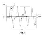
- FIG. 4the figure is a plot 400 of a sampled Rogowski coil 130 A, 130 B output while sensing the inrush current of a power transformer 110 according to one exemplary embodiment of the present invention.
- Plot 400illustrates the output of a Rogowski coil 130 A, 130 B sensing the inrush current of a power transformer 110 similar to that illustrated in Plot 320 .
- the points along the curve of Plot 400may represent discrete time samples, or snapshots, of the Rogowski coil 130 A, 130 B output.
- the five samples in region 430 of the Plot 400can represent a low di/dt period similar to region 330 of Plot 320 .
- Such low di/dt periodsmay be used by the differential protection controller 150 to detect an inrush condition.
- the differential protection controller 150may operate to detect multiple sequential samples that lie between the lower limit along line 440 B and the upper limit along line 440 A. In such an example, when multiple samples 420 in a row lie between the limits 440 A, 440 B, then an inrush condition may be detected and used to block protection relay operation.
- FIG. 5the figure shows a logical flow diagram of a process 500 for detecting transformer inrush current in a differential protection system using Rogowski coils according to one exemplary embodiment of the present invention.
- Certain steps in the processes or process flow described in the logic flow diagram referred to hereinafternaturally precede others for the invention to function as described.
- the inventionis not limited to the order of the steps described if such order or sequence does not alter the functionality of the invention. That is, it is recognized that some steps may be performed before, after, or in parallel with other steps without departing from the scope or spirit of the invention.
- the current flowing in the primary conductor 120 Amay be sensed by the primary side Rogowski coil 130 A and the current flowing in the secondary conductor 120 B may be sensed by the secondary side Rogowski coil 130 B.
- the voltage induced in the respective Rogowski coilsis proportional to the rate of change of current being sensed. This rate of change of current is also called the first time derivative of the current, or di/dt, or change in current per change in time.
- the primary side Rogowski coil 130 Aoutputs a signal proportional to the primary di/dt and the secondary side Rogowski coil 130 B outputs a signal proportional to the secondary di/dt.
- the processor 150samples the primary di/dt signal and the secondary di/dt signal to obtain a discrete time representation of the two di/dt signals, also known as the sampled di/dt signals.
- the sampling ratemay be sixteen times per cycle of the power signal, sixty-four times per cycle of the power signal, 256 times per cycle of the power signal, any sampling rate allowed by the Nyquist-Shannon sampling theorem, any fraction, factor, or multiple thereof, or any other suitable quantity of samples per cycle.
- Step 535the processor 150 subtracts the sampled di/dt signals obtained in Step 530 to calculate a discrete time, or sampled, difference between the primary di/dt signal and the secondary di/dt signal for each set of discrete di/dt signals (in other words, for each primary di/dt and secondary di/dt samples at the same time).
- the differencecan be called the differential di/dt, or the sampled differential di/dt.
- Step 540the processor 150 determines if the sampled differential di/dt falls within a low range for at least a predetermined number ‘n’ of sequential samples per cycle of the power signal.
- the number of predetermined number ‘n’ of sequential samplescan be based on a percentage of the number of samples in one cycle according to the sampling rate.
- the predetermined number ‘n’ of sequential samplescan be at least one-fifth of the number of samples in one cycle, one-fourth the number of samples in one cycle, or another suitable percentage of the number of samples in one cycle.
- the sampling ratecan be sixteen samples per cycle, and the predetermined number ‘n’ of sequential samples can be three or four.
- the values specifying the low rangemay be a function of the peak current, inrush current, or rated current, or may be predetermined to represent low values of di/dt.
- the limitsmay be plus or minus 5%, 10%, 20%, 25%, 30%, or other suitable percentage of any of the peak current, inrush current, or rated current. These are merely examples, and any other suitable limit may be specified either as a constant or as a function of some other suitable system parameter. A typical value of about 10% of a peak current may be use in one exemplary application.
- the low rangecan be the range between lines 440 A and 440 B as previously discussed with respect to FIG. 4 .
- the quantity ‘n’may be one quarter of the number of samples per power cycle, as one example representing the requirement that the low values be present for one quarter of the cycle.
- the quantity ‘n’also may be any other suitable fraction of the number of samples per cycle or any other previously determined or adaptive quantity. If the sampled di/dt did not fall within the low range for ‘n’ sequential samples or more, then the process loops back to Step 530 where the next samples of the di/dt signals are obtained. If the sampled di/dt has, in fact, been within the low range for ‘n’ sequential samples or more, then the process 500 has detected an inrush condition and will proceed to Step 550 to block the operation of the differential protection element of the protection relay for the next ‘m’ cycles as discussed in more detail below with respect to Step 580 .
- the value ‘m’may be any predetermined number of cycles provided for the inrush current to settle into its steady state. Alternatively, the quantity ‘m’ may be adaptive to the inrush current magnitude or rate of the inrush current damping.
- the processor 150obtains the primary current I p from the primary di/dt as well as the secondary current I s from the secondary di/dt.
- the currentscan be obtained from the di/dt signals using scaling and phase shifting.
- the Rogowski coil output signalshave voltages proportional to the currents being sensed but shifted 90 degrees in phase.
- a phase shift and scalar magnitude correction in the frequency domainmay be used to obtain the two current signals from the two di/dt signals.
- the currentscan be obtained from the di/dt signals through more traditional integration performed in the digital domain, analog domain, or by any other method of integrating.
- step 565the primary current I p and the secondary current I s can be subtracted to obtain I diff or the differential current.
- the differential currentcan be the difference between the current of the primary conductor 120 A and the current of the secondary conductor 120 B.
- Step 570the processor 150 determines if I diff is greater than the differential threshold.
- the differential thresholdmay be constant, or it may be provided by a slope function such as those examples discussed previously with respect to FIG. 2 . If processor 150 determines that I diff is not greater than the differential threshold, then the process 500 loops back through Step 560 to continue obtaining the differential current and evaluating the differential current against the threshold current. If it is decided that I diff is, in fact, greater than the differential threshold, then there may be a fault condition and the process 500 continues to Step 580 .
- Such a fault conditionmay be a potentially false fault condition if the power transformer 110 is currently receiving inrush current.
- Step 580the processor 150 determines if Step 550 is blocking the protection relay. Such blocking can be due to the detection of an inrush condition. If the protection relay is, in fact, blocked then the relay is, not operated and the process 500 returns to Step 560 to continue obtaining the differential current and evaluating the differential current against the differential threshold. If the protection relay is not blocked, then the process continues to Step 590 where the protection relay is operated.
- the protection relaymay be operated to isolate the power transformer 110 . Such isolation may protect the power system from damage or losses due to system faults.
- the systemmay be manually or automatically reset and process 500 may be reentered to provide continued system protection.
Landscapes
- Engineering & Computer Science (AREA)
- Power Engineering (AREA)
- Protection Of Transformers (AREA)
- Emergency Protection Circuit Devices (AREA)
- Measuring Instrument Details And Bridges, And Automatic Balancing Devices (AREA)
Abstract
Description
- The present invention relates to a differential protection system for power transformers and more specifically to a power transformer protection system using Rogowski coils for current sensing and for detecting inrush current of the power transformer.
- A power transformer is used to step up, or step down, a voltage. That is, the output voltage is the input voltage times a step factor. The step factor is generally called the transformer ratio and is also known as turns ratio. This ratio is defined as the ratio of the primary and secondary voltages for a two winding transformer. Generally, a transformer that steps up voltage will step down current while a transformer that steps down voltage will step up current. Since power equals voltage times current, power is the same on both sides of the transformer, ignoring transformer losses. Aside from being multiplied by the transformer ratio, the current entering a power transformer should be equal to the current leaving the power transformer. A difference between the current entering the transformer and the current leaving the transformer can indicate a fault within the transformer where current is being diverted into the transformer rather than passing through the transformer.
- Differential protection of power transformers is a technique that compares the current entering the transformer with the current leaving the transformer. One side of a transformer is the primary while the other side is the secondary. Usually, the side where power enters is the primary. A differential protection system senses the current at the primary side and also senses the current at the secondary side. The area between the current sensors is called the protection zone. The differential protection system determines if there is an excessive difference, aside from the scaling factor, between the two current sensors. If the difference exceeds the relay setting (differential threshold), a fault within the protection zone is likely, and a protection relay initiates operation of a circuit breaker or other device to isolate the power transformer.
- The difference between the primary current and the secondary current that is required to trip the differential protection system and to cause the protection relay to operate can be called the differential threshold of the differential protection system. A differential protection system with a lower differential threshold may be more sensitive, but can be falsely triggered by non fault events.
- Generally, current transformers are used in a differential protection system to sense the primary current and the secondary current. Current transformers typically have iron cores and may saturate. Transformer core saturation occurs when more magnetic flux is induced within the transformer than can be handled by the core. When a transformer core saturates, it may lose its inductive characteristics allowing currents in the transformer windings to temporarily spike to extremely high levels. Unequal saturation between the current transformer sensing the primary current and the current transformer sensing the secondary current is an example of a false triggering event as no fault is involved.
- To avoid erroneously detecting fault conditions for reasons such as current sensor saturation, the differential threshold of a protection system may be set as a percentage of the current passing through the transformer. This differential threshold setting generally is provided by adding restraint components to stabilize the protection relay. Relay stabilization improves performance since high through currents will require a higher differential current to operate the relay. This quality generally is characterized by the slope of the relay. The slope is given by a sloped line that relates the current passing through the transformer with the differential threshold setting. The line is sloped because a higher through-current implies setting a higher differential threshold. Such a relationship may be illustrated using an upward sloping line when plotted on a graph with through-current on the horizontal axis and differential current threshold on the vertical axis. In systems where the relay is controlled digitally, multiple slopes may be utilized to avoid inappropriately operating the protection relay in conditions involving severe current transformer saturation caused by high fault currents.
- Inrush current is the input current drawn by a device when power is initially applied to the device. Inrush current is a startup transient. When a power transformer is first energized, an inrush current much larger than the rated transformer current can flow for up to tens of seconds. That is, when a transformer is first powered on, a higher current must flow into the transformer to establish the magnetic fields within the transformer core. Inrush current flows at the energizing side of the transformer, while there may be little or no current flow at the other side of transformer. In a networked application, the energizing side of the transformer may be the primary side or the secondary side. Since inrush current generally flows on only one side of the transformer, the current differential between the primary and secondary sides of the transformer easily can exceed the differential threshold of the differential protection system and can cause the protection relay to isolate the power transformer even though an actual fault does not exist.
- The unnecessary isolation of a power transformer during an inrush condition can be mitigated by detecting the inrush current and, in response, blocking the differential protection element within the protection relay. Traditionally, inrush current is detected by extracting the second harmonic component from the inrush current using mathematical algorithms. This technique typically involves applying filters to the current measurements to isolate the second harmonic component which is a portion of the current signal at about twice the operating frequency of the power system. Various filter designs, of differing complexities, have been developed to extract this second harmonic information. Varying response characteristics at this second harmonic for different transformers, as well as the complexity of the related filter designs, often complicate such traditional approaches.
- Accordingly, there is a need in the art for a power transformer differential protection system for more accurately detecting inrush current and to reduce the unnecessary isolation of the power transformer during an inrush condition.
- The present invention relates to a differential protection system for power transformers using Rogowski coils as current sensors. A Rogowski coil can comprise a helical, or quasi-helical, coil of wire with the lead from one end returning through the center of the coil to the other end, so that both leads are at one end of the coil. The coil then may be formed around a straight conductor where the current in the straight conductor is to be measured. The voltage that is induced in the Rogowski coil is proportional to the rate of change of current in the straight conductor. This rate of change of current also is called the first time derivative of the current, or di/dt, or change in current per change in time. Thus, the output of the Rogowski coil can be used to represent di/dt where “i” is the current in the straight conductor being measured. Also, the output of a Rogowski coil can be connected to an electronic integrator circuit to provide a signal that is proportional to the sensed current.
- Rogowski coils can provide low inductance and excellent response to fast-changing currents since they have air cores rather than an iron core. Without an iron core to saturate, a Rogowski coil can be highly linear even in high current applications. Furthermore, having reduced saturation concerns, the Rogowski coil protection system may employ a single slope response with increased sensitivity. Also, the geometry of a Rogowski coil may provide a current sensor that is significantly immune to electromagnetic interference.
- The present invention further relates to methods for detecting inrush current for a power transformer. Using the output of the Rogowski coils, which is proportional to the derivative of the sensed current, periodic low di/dt periods in the sensed current are used to detect power transformer inrush conditions. Another aspect of the present invention relates to discrete time sampling techniques for identifying the low di/dt portions within the sensed current. Effective detection of power transformer inrush conditions can enable blocking of the protection system during inrush where the differential current may exceed the differential threshold without the presence of an actual fault.
- The discussion of transformer protection systems in this summary is for illustration only. Various aspects of the present invention may be more clearly understood and appreciated from a review of the following detailed description of the disclosed embodiments and by reference to the drawings and the claims that follow. Moreover, other aspects, systems, methods, features, advantages, and objects of the present invention will become apparent to one with skill in the art upon examination of the following drawings and detailed description. It is intended that all such aspects, systems, methods, features, advantages, and objects are included within this description, are within the scope of the present invention, and are protected by the accompanying claims.
FIG. 1 is a circuit diagram illustrating a schematic representation of a transformer and a differential protection system using Rogowski coil current sensors according to one exemplary embodiment of the present invention.FIG. 2 is a graph illustrating relay slopes used in differential protection systems for transformers according to a conventional method and according to one exemplary embodiment of the present invention.FIG. 3 is a plot illustrating the inrush current of a power transformer and a corresponding plot illustrating the output of a Rogowski coil according to one exemplary embodiment of the present invention.FIG. 4 is a plot of a sampled Rogowski coil output while sensing the inrush current of a power transformer according to one exemplary embodiment of the present invention.FIG. 5 is a logical flow diagram of a process for detecting transformer inrush current in a differential protection system using Rogowski coils according to one exemplary embodiment of the present invention.- Many aspects of the invention will be better understood with reference to the above drawings. The elements and features shown in the drawings are not to scale, emphasis instead being placed upon clearly illustrating the principles of exemplary embodiments of the present invention. Moreover, certain dimensions may be exaggerated to help visually convey such principles. In the drawings, reference numerals designate like or corresponding, but not necessarily identical, elements throughout the several views.
- The present invention relates to a differential protection system for power transformers using Rogowski coils as current sensors and to methods for detecting inrush current for a power transformer. Using the output of the Rogowski coils, which is proportional to the derivative of the sensed current, periodic low di/dt periods in the sensed current are used to detect power transformer inrush conditions. Discrete time sampling techniques can be used for identifying the low di/dt portions within the sensed current. Effective detection of power transformer inrush conditions can enable blocking of the protection system during inrush where the differential current may exceed the differential threshold without the presence of an actual fault.
- The invention can be embodied in many different forms and should not be construed as limited to the embodiments set forth herein; rather, these embodiments are provided so that this disclosure will be thorough and complete, and will fully convey the scope of the invention to those having ordinary skill in the art. Furthermore, all “examples” or “exemplary embodiments” given herein are intended to be non-limiting, and among others supported by representations of the present invention.
- Turning now to
FIG. 1 , the figure is a circuit diagram illustrating atransformer 110 and adifferential protection system 100 using Rogowski coilcurrent sensors power transformer 110 may comprise aprimary transformer coil 110A and asecondary transformer coil 110B. Alternating current (AC) may be conducted into, or out of, theprimary transformer coil 110A throughprimary conductor 120A. Alternating current may be conducted into, or out of, thesecondary transformer coil 110B throughprimary conductor 120B. The current flowing in theprimary conductor 120A may be sensed by a primaryside Rogowski coil 130A. The current flowing in thesecondary conductor 120B may be sensed by a secondaryside Rogowski coil 130B. The portion of thesystem 100 between the primaryside Rogowski coil 130A and the secondaryside Rogowski coil 130B includes thetransformer 110. This portion of the system between the sensor coils130A,130B can be referred to as the protection zone of thedifferential protection system 100. - The output of the primary
side Rogowski coil 130A is the primaryside sense signal 140A. The primaryside sense signal 140A may be proportional to the first time derivative of the primary side current flowing in theprimary conductor 120A. The output of the secondaryside Rogowski coil 130B is the secondaryside sense signal 140B. The secondaryside sense signal 140B may be proportional to the first time derivative of the secondary side current flowing in thesecondary conductor 120B. - A
differential protection controller 150 can process the primaryside sense signal 140A and the secondaryside sense signal 140B to detect transformer inrush currents and to control the operation of a protection relay. In exemplary applications, theprotection controller 150 may be referred to as the relay. The protection relay (not illustrated inFIG. 1 ) can isolate thetransformer 110 when a fault condition occurs based upon an output of theprotection controller 150. This isolation can be provided by a circuit breaker or other device operated by the protection relay. During inrush, a large difference between the current flowing in theprimary conductor 120A and the current flowing in thesecondary conductor 120B may occur even though a fault is not present within the zone of protection. By detecting an inrush condition, thedifferential protection controller 150 can block the unnecessary operation of the protection relay and associated circuit breakers during inrush. - The
differential protection controller 150 may be operable to carry out a process for detecting power transformer inrush current similar to process500 detailed with respect toFIG. 5 . Thedifferential protection controller 150 may comprise a microprocessor, a microcontroller, a digital signal processor, an analog signal processing circuit, an application specific integrated circuit (ASIC), a field programmable gate array (FPGA), a system on chip (SOC), a complex programmable gate array (CPLD), digital logic, combinational logic, sequential logic, any other computing mechanism, logic mechanism, state machine, or any combination thereof. Thedifferential protection controller 150 may comprise software, firmware, hardware, or any combination thereof. - Although only a single phase of the
transformer 110 is illustrated inFIG. 1 , theprotection system 100 may be operated with polyphase power systems. For example, two-phase, three-phase, or other such power transformers may be protected. In a three-phase system, three circuit conductors carry three alternating currents of the same frequency where, using one conductor as a reference, the other two currents are delayed in time by one-third and two-thirds of a cycle, respectively. A three-phase power transformer may have three primary windings and three secondary windings. The sensors130 of thedifferential protection system 100 may be employed on any one of the three phases, any two of the phases, or all three of the phases. Even if the sensing is on only one or two of the phases, the protection relay, or relays, may isolate all three phases of the transformer using circuit breaker or other device operation. An indication of an inrush condition on one phase may be used to block any of the phase protection elements in the protection relay. Such operation can be referred to as cross-phase blocking or phase dependent blocking. Alternatively, the protection relay, or relays, may isolate each of the three phases of the transformer individually. - Turning now to
FIG. 2 , the figure is agraph 200 illustrating relay slopes used in differential protection systems for transformers according to a conventional method and according to one exemplary embodiment of the present invention. The horizontal axis of thegraph 200 represents the current flowing through the transformer from theprimary conductor 120A to thesecondary conductor 120B. The vertical axis of the graph represents the differential current (ΔI). Referring to theexemplary system 100 illustrated inFIG. 1 , the differential current is the difference between the current flowing in theprimary conductor 120A and the current flowing in thesecondary conductor 120B. With respect to this differential current, and throughout the entire disclosure, it should be understood that comparing, or subtracting, primary and secondary currents can involve first adjusting one or both of the primary or secondary currents for the transformer ratio and/or the sensor ratio. - To avoid erroneously detecting fault conditions for reasons such as current sensor saturation, the differential threshold of a protection system may be set as a percentage of the current passing through the transformer. This differential threshold setting can be made by adding restraint components to stabilize the protection relay. Relay stabilization improves performance since high through currents will require a higher differential current to operate the relay. This quality generally is characterized by the slope of the relay.
- The slope of a relay may be illustrated as a sloped line that relates the current passing through the transformer with the differential threshold setting. The line is sloped because a higher through-current implies setting a higher differential threshold. Such a relationship may be illustrated using an upward sloping line when plotted on a graph with through-current on the horizontal axis and differential current threshold on the vertical axis. In systems where the relay is controlled digitally, multiple slopes may be utilized to avoid inappropriately operating the protection relay in conditions involving severe current transformer saturation caused by high fault currents.
Curve 210 of thegraph 200 illustrates an example double slope relay response that may be seen in traditional systems using iron-core current transformers to sense current. Multiple slopes may be utilized to avoid inappropriately operating the protection relay in conditions involving severe current transformer saturation. Such current transformer saturation may be caused by high fault currents. The increased slope ofcurve 210 at higher through currents represents an increase in the differential threshold current. Such an increase in the differential threshold current means that, at higher through-currents, a greater difference between the primary and secondary is required to trip the protection relay. In other words, for higher through-currents, the sensitivity of theprotection system 100 may need to be reduced to avoid false positive operation that may be induced by increased core saturation in the sensing transformers at the higher currents.- In a protection system using Rogowski coils130A,130B to sense current according to an exemplary embodiment of the invention, saturation of the sensing mechanism may be substantially eliminated. Thus, the sensing coils130A,130B may deliver a more accurate representation of the current flowing in the
primary conductor 120A and the current flowing in thesecondary conductor 120B even at high through current operation of thetransformer 110. With reduced need to accommodate errors in the sensing of the currents, thesystem 100 using Rogowski coils130A,130B can use a more sensitive relay slope such as that illustrated bycurve 220 of thegraph 200. Region 260 of thegraph 200 represents the blocking zone where operation of the protection relay is blocked.Region 240 of thegraph 200 represents the operating zone where the operation of the protection relay is not blocked. When the operation of the protection relay is not blocked, the protection relay may operate to isolate the power transformer as the differential current exceeds the differential threshold representing a fault condition.Region 250 of thegraph 200 represents a zone where the traditional current transformer based systems would block operation of the relay, but where Rogowski coil basedsystems 100 according to an exemplary embodiment of the invention may allow the protection relay to operate. This addedoperation zone 250 for such Rogowski coil based systems may provide a more sensitive protective differential protection solution.- Turning now to
FIG. 3 , the figure is aplot 310 illustrating the inrush current of apower transformer 110 and acorresponding plot 320 illustrating the output of aRogowski coil Plot 310 illustrates the inrush current of apower transformer 110. Inrush current is the input to thepower transformer 110 when power is initially applied to thetransformer 110. Inrush current is a startup transient. When a power transformer is first energized, an inrush current much larger than the rated transformer current can flow for up to tens of seconds or more. In a networked application, thetransformer 110 may be energized from the primary side or from the secondary side. Since inrush current may generally flow only to one side of the transformer, the inrushcurrent plot 310 may be related to either one of thesense transformers Plot 320 illustrates the output of aRogowski coil plot 310. The voltage that is induced in the Rogowski coil is proportional to the rate of change of current being sensed. This rate of change of current is also called the first time derivative of the current, or di/dt, or change in current per change in time. The substantiallyflat portions 330 of each cycle of theplot 330 represent periods of low rate of current changes. These low di/dt periods 330 may be used by thedifferential protection controller 150 to detect an inrush condition. Detecting an inrush condition can allow blocking operation of the protection relay during inrush. Even though the differential threshold of the protection system may be exceeded during inrush, there may be no actual fault condition.- Turning now to
FIG. 4 , the figure is aplot 400 of a sampledRogowski coil power transformer 110 according to one exemplary embodiment of the present invention.Plot 400 illustrates the output of aRogowski coil power transformer 110 similar to that illustrated inPlot 320. The points along the curve ofPlot 400, three examples of which are labeled420, may represent discrete time samples, or snapshots, of theRogowski coil region 430 of thePlot 400 can represent a low di/dt period similar toregion 330 ofPlot 320. Such low di/dt periods may be used by thedifferential protection controller 150 to detect an inrush condition. For example, thedifferential protection controller 150 may operate to detect multiple sequential samples that lie between the lower limit alongline 440B and the upper limit alongline 440A. In such an example, whenmultiple samples 420 in a row lie between thelimits - Turning now to
FIG. 5 , the figure shows a logical flow diagram of aprocess 500 for detecting transformer inrush current in a differential protection system using Rogowski coils according to one exemplary embodiment of the present invention. Certain steps in the processes or process flow described in the logic flow diagram referred to hereinafter naturally precede others for the invention to function as described. However, the invention is not limited to the order of the steps described if such order or sequence does not alter the functionality of the invention. That is, it is recognized that some steps may be performed before, after, or in parallel with other steps without departing from the scope or spirit of the invention. - In
Step 510, the current flowing in theprimary conductor 120A may be sensed by the primaryside Rogowski coil 130A and the current flowing in thesecondary conductor 120B may be sensed by the secondaryside Rogowski coil 130B. The voltage induced in the respective Rogowski coils is proportional to the rate of change of current being sensed. This rate of change of current is also called the first time derivative of the current, or di/dt, or change in current per change in time. Thus, the primaryside Rogowski coil 130A outputs a signal proportional to the primary di/dt and the secondaryside Rogowski coil 130B outputs a signal proportional to the secondary di/dt. - In
Step 530, theprocessor 150 samples the primary di/dt signal and the secondary di/dt signal to obtain a discrete time representation of the two di/dt signals, also known as the sampled di/dt signals. Examples of the sampling rate may be sixteen times per cycle of the power signal, sixty-four times per cycle of the power signal, 256 times per cycle of the power signal, any sampling rate allowed by the Nyquist-Shannon sampling theorem, any fraction, factor, or multiple thereof, or any other suitable quantity of samples per cycle. - In
Step 535, theprocessor 150 subtracts the sampled di/dt signals obtained inStep 530 to calculate a discrete time, or sampled, difference between the primary di/dt signal and the secondary di/dt signal for each set of discrete di/dt signals (in other words, for each primary di/dt and secondary di/dt samples at the same time). The difference can be called the differential di/dt, or the sampled differential di/dt. - In
Step 540, theprocessor 150 determines if the sampled differential di/dt falls within a low range for at least a predetermined number ‘n’ of sequential samples per cycle of the power signal. - In an exemplary embodiment, the number of predetermined number ‘n’ of sequential samples can be based on a percentage of the number of samples in one cycle according to the sampling rate. For example, the predetermined number ‘n’ of sequential samples can be at least one-fifth of the number of samples in one cycle, one-fourth the number of samples in one cycle, or another suitable percentage of the number of samples in one cycle. In an exemplary embodiment, the sampling rate can be sixteen samples per cycle, and the predetermined number ‘n’ of sequential samples can be three or four.
- In exemplary embodiments, the values specifying the low range may be a function of the peak current, inrush current, or rated current, or may be predetermined to represent low values of di/dt. For example, the limits may be plus or minus 5%, 10%, 20%, 25%, 30%, or other suitable percentage of any of the peak current, inrush current, or rated current. These are merely examples, and any other suitable limit may be specified either as a constant or as a function of some other suitable system parameter. A typical value of about 10% of a peak current may be use in one exemplary application. The low range can be the range between
lines FIG. 4 . The quantity ‘n’ may be one quarter of the number of samples per power cycle, as one example representing the requirement that the low values be present for one quarter of the cycle. The quantity ‘n’ also may be any other suitable fraction of the number of samples per cycle or any other previously determined or adaptive quantity. If the sampled di/dt did not fall within the low range for ‘n’ sequential samples or more, then the process loops back toStep 530 where the next samples of the di/dt signals are obtained. If the sampled di/dt has, in fact, been within the low range for ‘n’ sequential samples or more, then theprocess 500 has detected an inrush condition and will proceed to Step550 to block the operation of the differential protection element of the protection relay for the next ‘m’ cycles as discussed in more detail below with respect toStep 580. The value ‘m’ may be any predetermined number of cycles provided for the inrush current to settle into its steady state. Alternatively, the quantity ‘m’ may be adaptive to the inrush current magnitude or rate of the inrush current damping. - In
Step 560, theprocessor 150 obtains the primary current Ipfrom the primary di/dt as well as the secondary current Isfrom the secondary di/dt. The currents can be obtained from the di/dt signals using scaling and phase shifting. The Rogowski coil output signals have voltages proportional to the currents being sensed but shifted 90 degrees in phase. Thus, a phase shift and scalar magnitude correction in the frequency domain may be used to obtain the two current signals from the two di/dt signals. Alternatively, the currents can be obtained from the di/dt signals through more traditional integration performed in the digital domain, analog domain, or by any other method of integrating. - In
step 565, the primary current Ipand the secondary current Iscan be subtracted to obtain Idiffor the differential current. The differential current can be the difference between the current of theprimary conductor 120A and the current of thesecondary conductor 120B. - In
Step 570, theprocessor 150 determines if Idiffis greater than the differential threshold. The differential threshold may be constant, or it may be provided by a slope function such as those examples discussed previously with respect toFIG. 2 . Ifprocessor 150 determines that Idiffis not greater than the differential threshold, then theprocess 500 loops back throughStep 560 to continue obtaining the differential current and evaluating the differential current against the threshold current. If it is decided that Idiffis, in fact, greater than the differential threshold, then there may be a fault condition and theprocess 500 continues to Step580. Such a fault condition may be a potentially false fault condition if thepower transformer 110 is currently receiving inrush current. - In
Step 580, theprocessor 150 determines ifStep 550 is blocking the protection relay. Such blocking can be due to the detection of an inrush condition. If the protection relay is, in fact, blocked then the relay is, not operated and theprocess 500 returns to Step560 to continue obtaining the differential current and evaluating the differential current against the differential threshold. If the protection relay is not blocked, then the process continues to Step590 where the protection relay is operated. - In
Step 590, the protection relay may be operated to isolate thepower transformer 110. Such isolation may protect the power system from damage or losses due to system faults. After the protection relay is operated, the system may be manually or automatically reset andprocess 500 may be reentered to provide continued system protection. - From the foregoing, it will be appreciated that an embodiment of the present invention overcomes the limitations of the prior art. Those skilled in the art will appreciate that the present invention is not limited to any specifically discussed application and that the embodiments described herein are illustrative and not restrictive. From the description of the exemplary embodiments, equivalents of the elements shown therein will suggest themselves to those skilled in the art, and ways of constructing other embodiments of the present invention will suggest themselves to practitioners of the art. Therefore, the present invention is to be provided the scope set forth by the claims that follow.
Claims (24)
Priority Applications (8)
| Application Number | Priority Date | Filing Date | Title |
|---|---|---|---|
| US11/999,813US7738221B2 (en) | 2007-12-07 | 2007-12-07 | Transformer inrush current detector |
| PCT/US2008/084339WO2009073407A1 (en) | 2007-12-07 | 2008-11-21 | Transformer inrush current detector |
| ES08857782.0TES2542877T3 (en) | 2007-12-07 | 2008-11-21 | Transformer input current detector |
| BRPI0820011-4ABRPI0820011A2 (en) | 2007-12-07 | 2008-11-21 | Current detector directed into the transformer |
| EP08857782.0AEP2223404B1 (en) | 2007-12-07 | 2008-11-21 | Transformer inrush current detector |
| MX2010006153AMX2010006153A (en) | 2007-12-07 | 2008-11-21 | Transformer inrush current detector. |
| CA2707481ACA2707481C (en) | 2007-12-07 | 2008-11-21 | Transformer inrush current detector |
| TW097145879ATW200934027A (en) | 2007-12-07 | 2008-11-27 | Transformer inrush current detector |
Applications Claiming Priority (1)
| Application Number | Priority Date | Filing Date | Title |
|---|---|---|---|
| US11/999,813US7738221B2 (en) | 2007-12-07 | 2007-12-07 | Transformer inrush current detector |
Publications (2)
| Publication Number | Publication Date |
|---|---|
| US20090147412A1true US20090147412A1 (en) | 2009-06-11 |
| US7738221B2 US7738221B2 (en) | 2010-06-15 |
Family
ID=40718099
Family Applications (1)
| Application Number | Title | Priority Date | Filing Date |
|---|---|---|---|
| US11/999,813Active2028-03-09US7738221B2 (en) | 2007-12-07 | 2007-12-07 | Transformer inrush current detector |
Country Status (8)
| Country | Link |
|---|---|
| US (1) | US7738221B2 (en) |
| EP (1) | EP2223404B1 (en) |
| BR (1) | BRPI0820011A2 (en) |
| CA (1) | CA2707481C (en) |
| ES (1) | ES2542877T3 (en) |
| MX (1) | MX2010006153A (en) |
| TW (1) | TW200934027A (en) |
| WO (1) | WO2009073407A1 (en) |
Cited By (24)
| Publication number | Priority date | Publication date | Assignee | Title |
|---|---|---|---|---|
| US20090230948A1 (en)* | 2006-11-06 | 2009-09-17 | Cooper Technologies Company | Rogowski Coil Assembly and Methods |
| US20100315188A1 (en)* | 2009-06-15 | 2010-12-16 | Advanced Power Technologies, Llc | Apparatus and method for cooling power transformers |
| US20120194949A1 (en)* | 2011-01-27 | 2012-08-02 | Lsis Co., Ltd | Relay and method for protecting transformer, and transformer protecting system having the same |
| US20130021705A1 (en)* | 2011-07-22 | 2013-01-24 | Lsis Co., Ltd. | Fault current limiter |
| US20130021706A1 (en)* | 2011-07-22 | 2013-01-24 | Lsis Co., Ltd. | Fault current limiter |
| US20130038971A1 (en)* | 2010-06-03 | 2013-02-14 | Shakira Limited | Arc fault detector for ac or dc installations |
| ES2412604A1 (en)* | 2012-12-20 | 2013-07-11 | Universidad Politécnica de Madrid | Blocking method of differential protection to avoid unwanted triggering based on joint supervision of phases (Machine-translation by Google Translate, not legally binding) |
| US20130242439A1 (en)* | 2011-09-06 | 2013-09-19 | Andre Pierre Perra | Motor Protection and Control Apparatus, System, and/or Method |
| CN103683198A (en)* | 2013-12-03 | 2014-03-26 | 昆明理工大学 | Excitation surge current fast identification method based on planar adjacent point distances formed by differential current adjacent order difference |
| JP2015529444A (en)* | 2012-09-11 | 2015-10-05 | 南京南端▲継▼保▲電気▼有限公司Nr Electric Co., Ltd | Frequency conversion differential protection method for output transformer in static frequency converter system |
| CN104967097A (en)* | 2015-06-26 | 2015-10-07 | 国网山东省电力公司经济技术研究院 | Recognition method of excitation inrush current based on support vector classifier |
| US20150293166A1 (en)* | 2012-11-26 | 2015-10-15 | Siemens Aktiengesellschaft | Differential Protection Method and Protective Apparatus for Carrying Out a Differential Protection Method |
| WO2016089351A1 (en)* | 2014-12-01 | 2016-06-09 | South Dakota Board Of Regents | Power transformers with fault-limiting capability |
| WO2016176682A1 (en)* | 2015-04-30 | 2016-11-03 | Abb Inc. | Detecting cyber-attacks and sensor failures in digital substations |
| WO2015187636A3 (en)* | 2014-06-03 | 2017-05-04 | Cooper Technologies Company | Power transformer inrush current detector |
| EP3204636A4 (en)* | 2014-10-10 | 2018-05-02 | ABB Schweiz AG | Method and system for protecting wind farm during disconnection to utility grid |
| CN108173240A (en)* | 2017-12-19 | 2018-06-15 | 华中科技大学 | A transformer excitation inrush current identification method and system based on composite time difference method |
| US10495680B2 (en)* | 2017-06-14 | 2019-12-03 | Schweitzer Engineering Laboratories, Inc. | Systems and methods for detecting current transformer ultrasaturation to enhance relay security and dependability |
| CN111740383A (en)* | 2020-06-29 | 2020-10-02 | 江苏大唐国际吕四港发电有限责任公司 | Method for eliminating inrush current influence in coordinated control of generator set |
| CN112039021A (en)* | 2020-09-08 | 2020-12-04 | 河南理工大学 | Transformer excitation inrush current identification method based on differential waveform parameters |
| US10886722B2 (en) | 2016-01-26 | 2021-01-05 | Shakira Limited | Arc fault current detector |
| DE102019120400A1 (en)* | 2019-07-29 | 2021-02-04 | Friedrich-Alexander-Universität Erlangen-Nürnberg | Method for the detection of an inrush event, computer program and disconnection device |
| CN112865018A (en)* | 2021-01-08 | 2021-05-28 | 河海大学 | Method for protecting multi-end convergence transformer of energy storage power station |
| US20210203147A1 (en)* | 2018-05-30 | 2021-07-01 | Nr Electric Co., Ltd | Longitudinal Differential Protection Method Of Transformer |
Families Citing this family (10)
| Publication number | Priority date | Publication date | Assignee | Title |
|---|---|---|---|---|
| US7638999B2 (en)* | 2006-04-07 | 2009-12-29 | Cooper Technologies Company | Protective relay device, system and methods for Rogowski coil sensors |
| EP2357374B1 (en)* | 2010-01-29 | 2016-02-17 | Levitronix GmbH | Magnetic bearing device |
| WO2012155975A1 (en) | 2011-05-19 | 2012-11-22 | Abb Technology Ag | System and method for protecting an electrical power grid |
| US8830645B2 (en)* | 2013-01-11 | 2014-09-09 | Cooper Technologies Company | Power spike mitigation |
| DE102015121299B4 (en)* | 2015-12-08 | 2017-08-10 | Zippy Technology Corp. | Peak current recording module |
| EP3447870B1 (en)* | 2017-08-22 | 2022-11-30 | Siemens Aktiengesellschaft | Differential protection method, differential protection device and differential protection system |
| MX2019015169A (en) | 2019-12-13 | 2021-06-14 | Prolec S A De C V | Apparatus and method for identifying a failure in windings of a distribution transformer. |
| US12424798B2 (en) | 2022-06-06 | 2025-09-23 | Vertiv Corporation | Outlet in-rush current limiter for intelligent power strip |
| EP4333228A1 (en)* | 2022-08-30 | 2024-03-06 | Hitachi Energy Ltd | Adaptive fault discrimination for a line differential protection |
| EP4415195A1 (en)* | 2023-02-10 | 2024-08-14 | Siemens Aktiengesellschaft | Method and arrangement for generating an error signal |
Citations (14)
| Publication number | Priority date | Publication date | Assignee | Title |
|---|---|---|---|---|
| US20010029433A1 (en)* | 1998-02-19 | 2001-10-11 | Scott Gary W. | Detection of arcing faults using bifurcated wiring system |
| US20020125877A1 (en)* | 1998-06-05 | 2002-09-12 | Chathan M. Cooke | Closely-coupled multiple-winding magnetic induction-type sensor |
| US20030112569A1 (en)* | 2002-03-14 | 2003-06-19 | Hitachi, Ltd. | Gas insulating apparatus and method for locating fault point thereof |
| US20040004794A1 (en)* | 2001-05-17 | 2004-01-08 | Yong-Cheol Kang | Relaying method for protecting a transformer using a difference of current |
| US20040012901A1 (en)* | 2002-07-12 | 2004-01-22 | Kojovic Ljubomir A. | Electrical arc furnace protection system |
| US20040027750A1 (en)* | 2002-08-06 | 2004-02-12 | Kabushiki Kaisha Toshiba | Digital protection and control device |
| US20040027748A1 (en)* | 2002-07-12 | 2004-02-12 | Kojovic Ljubomir A. | Electrical protection system |
| US6781361B2 (en)* | 2001-04-26 | 2004-08-24 | Analog Devices, Inc. | Apparatus and system for electrical power metering using digital integration |
| US20040183522A1 (en)* | 2003-03-19 | 2004-09-23 | Power Measurement Ltd. | Power line sensors and systems incorporating same |
| US20050248430A1 (en)* | 2004-05-10 | 2005-11-10 | Areva T&D Sa | Current transformer with rogowski type windings, comprising an association of partial circuits forming a complete circuit |
| US20060012374A1 (en)* | 2004-07-15 | 2006-01-19 | Kojovic Ljubomir A | Traveling wave based relay protection |
| US7180717B2 (en)* | 2002-07-12 | 2007-02-20 | Cooper Technologies Company | Electrical network protection system |
| US7227347B2 (en)* | 2002-09-12 | 2007-06-05 | Abb Services S.R.L. | Device and method for measuring a current |
| US20070236208A1 (en)* | 2006-04-07 | 2007-10-11 | Cooper Technologies Company | Protective relay device, system and methods for Rogowski coil sensors |
Family Cites Families (27)
| Publication number | Priority date | Publication date | Assignee | Title |
|---|---|---|---|---|
| CH554096A (en) | 1970-12-17 | 1974-09-13 | Merlin Gerin | SELECTIVE PROTECTION DEVICE FOR AN ELECTRICAL ENERGY DISTRIBUTION NETWORK. |
| CH608917A5 (en) | 1975-06-05 | 1979-01-31 | Bbc Brown Boveri & Cie | |
| JPS6326594Y2 (en) | 1981-03-16 | 1988-07-19 | ||
| US4446420A (en) | 1982-01-28 | 1984-05-01 | Hydro Quebec | Method and device for detecting and locating fault and/or partial discharges in a gas-insulated electrical equipment |
| US4709339A (en) | 1983-04-13 | 1987-11-24 | Fernandes Roosevelt A | Electrical power line parameter measurement apparatus and systems, including compact, line-mounted modules |
| US4570231A (en) | 1984-01-27 | 1986-02-11 | Richard H. Bunch | Fault finder |
| US4766549A (en) | 1984-11-30 | 1988-08-23 | Electric Power Research Institute, Inc. | Single-ended transmission line fault locator |
| FR2584193B1 (en) | 1985-06-28 | 1987-08-07 | Telemecanique Electrique | INDUCTIVE SENSOR FOR CURRENT MEASUREMENT |
| US4623949A (en) | 1985-09-06 | 1986-11-18 | Westinghouse Electric Corp. | Bus differential relay |
| JP2510498B2 (en)* | 1985-10-14 | 1996-06-26 | 東京電力株式会社 | Transformer failure detection method and device |
| CH669852A5 (en) | 1986-12-12 | 1989-04-14 | Lem Liaisons Electron Mec | |
| US4749940A (en) | 1986-12-22 | 1988-06-07 | General Electric Company | Folded bar current sensor |
| FR2634897A1 (en) | 1988-07-26 | 1990-02-02 | Alsthom | DEVICE FOR MEASURING PHASE CURRENTS OF A THREE-PHASE INSTALLATION |
| JP2997515B2 (en)* | 1990-07-27 | 2000-01-11 | 株式会社日立製作所 | Transformer protection system and protection method |
| US5115447A (en) | 1991-01-10 | 1992-05-19 | Ucar Carbon Technology Corporation | Arc furnace electrode control |
| FR2692074B1 (en) | 1992-06-05 | 1994-07-22 | Alsthom Gec | ROGOWSKI COIL. |
| US5434509A (en) | 1992-07-30 | 1995-07-18 | Blades; Frederick K. | Method and apparatus for detecting arcing in alternating-current power systems by monitoring high-frequency noise |
| FR2695482B1 (en) | 1992-09-10 | 1994-10-21 | Alsthom Gec | Measuring device using a Rogowski coil. |
| GB2286088B (en) | 1994-01-26 | 1997-09-24 | Gec Alsthom Ltd | A method of locating the position of a fault on a power transmission line |
| GB2288930B (en) | 1994-04-25 | 1998-01-21 | Gec Alsthom Ltd | Methods and apparatus for identifying faulted phases on an electric power transmission line |
| SE507043C2 (en) | 1996-08-29 | 1998-03-16 | Asea Brown Boveri | Measurement procedure at line error locator on HVDC lines |
| DE19640981A1 (en) | 1996-10-04 | 1998-04-16 | Asea Brown Boveri | Rogowski coil |
| TW475991B (en) | 1998-12-28 | 2002-02-11 | Nippon Kouatsu Electric Co Ltd | Fault point location system |
| US6313623B1 (en) | 2000-02-03 | 2001-11-06 | Mcgraw-Edison Company | High precision rogowski coil |
| EP1269796A4 (en) | 2000-03-17 | 2004-11-24 | Specialty Minerals Michigan | Process and apparatus for automatically controlling slag foaming |
| US6680608B2 (en) | 2002-02-27 | 2004-01-20 | Mcgraw-Edison Company | Measuring current through an electrical conductor |
| US6822457B2 (en) | 2003-03-27 | 2004-11-23 | Marshall B. Borchert | Method of precisely determining the location of a fault on an electrical transmission system |
- 2007
- 2007-12-07USUS11/999,813patent/US7738221B2/enactiveActive
- 2008
- 2008-11-21WOPCT/US2008/084339patent/WO2009073407A1/enactiveApplication Filing
- 2008-11-21MXMX2010006153Apatent/MX2010006153A/enactiveIP Right Grant
- 2008-11-21ESES08857782.0Tpatent/ES2542877T3/enactiveActive
- 2008-11-21EPEP08857782.0Apatent/EP2223404B1/ennot_activeNot-in-force
- 2008-11-21BRBRPI0820011-4Apatent/BRPI0820011A2/ennot_activeIP Right Cessation
- 2008-11-21CACA2707481Apatent/CA2707481C/ennot_activeExpired - Fee Related
- 2008-11-27TWTW097145879Apatent/TW200934027A/enunknown
Patent Citations (16)
| Publication number | Priority date | Publication date | Assignee | Title |
|---|---|---|---|---|
| US20010029433A1 (en)* | 1998-02-19 | 2001-10-11 | Scott Gary W. | Detection of arcing faults using bifurcated wiring system |
| US20020125877A1 (en)* | 1998-06-05 | 2002-09-12 | Chathan M. Cooke | Closely-coupled multiple-winding magnetic induction-type sensor |
| US6781361B2 (en)* | 2001-04-26 | 2004-08-24 | Analog Devices, Inc. | Apparatus and system for electrical power metering using digital integration |
| US20040004794A1 (en)* | 2001-05-17 | 2004-01-08 | Yong-Cheol Kang | Relaying method for protecting a transformer using a difference of current |
| US6958894B2 (en)* | 2001-05-17 | 2005-10-25 | Yong Cheol Kang | Relaying method for protecting a transformer using a difference of current |
| US20030112569A1 (en)* | 2002-03-14 | 2003-06-19 | Hitachi, Ltd. | Gas insulating apparatus and method for locating fault point thereof |
| US7180717B2 (en)* | 2002-07-12 | 2007-02-20 | Cooper Technologies Company | Electrical network protection system |
| US20040012901A1 (en)* | 2002-07-12 | 2004-01-22 | Kojovic Ljubomir A. | Electrical arc furnace protection system |
| US20040027748A1 (en)* | 2002-07-12 | 2004-02-12 | Kojovic Ljubomir A. | Electrical protection system |
| US20040027750A1 (en)* | 2002-08-06 | 2004-02-12 | Kabushiki Kaisha Toshiba | Digital protection and control device |
| US6954704B2 (en)* | 2002-08-06 | 2005-10-11 | Kabushiki Kaisha Toshiba | Digital protection and control device |
| US7227347B2 (en)* | 2002-09-12 | 2007-06-05 | Abb Services S.R.L. | Device and method for measuring a current |
| US20040183522A1 (en)* | 2003-03-19 | 2004-09-23 | Power Measurement Ltd. | Power line sensors and systems incorporating same |
| US20050248430A1 (en)* | 2004-05-10 | 2005-11-10 | Areva T&D Sa | Current transformer with rogowski type windings, comprising an association of partial circuits forming a complete circuit |
| US20060012374A1 (en)* | 2004-07-15 | 2006-01-19 | Kojovic Ljubomir A | Traveling wave based relay protection |
| US20070236208A1 (en)* | 2006-04-07 | 2007-10-11 | Cooper Technologies Company | Protective relay device, system and methods for Rogowski coil sensors |
Cited By (34)
| Publication number | Priority date | Publication date | Assignee | Title |
|---|---|---|---|---|
| US7902812B2 (en) | 2006-11-06 | 2011-03-08 | Cooper Technologies Company | Rogowski coil assembly and methods |
| US20090230948A1 (en)* | 2006-11-06 | 2009-09-17 | Cooper Technologies Company | Rogowski Coil Assembly and Methods |
| US20100315188A1 (en)* | 2009-06-15 | 2010-12-16 | Advanced Power Technologies, Llc | Apparatus and method for cooling power transformers |
| US8274769B2 (en)* | 2009-06-15 | 2012-09-25 | Advanced Power Technologies, Llc | Apparatus and method for cooling power transformers |
| US8743513B2 (en)* | 2010-06-03 | 2014-06-03 | Shakira Limited | Arc fault detector for AC or DC installations |
| US20130038971A1 (en)* | 2010-06-03 | 2013-02-14 | Shakira Limited | Arc fault detector for ac or dc installations |
| US20120194949A1 (en)* | 2011-01-27 | 2012-08-02 | Lsis Co., Ltd | Relay and method for protecting transformer, and transformer protecting system having the same |
| US8854776B2 (en)* | 2011-01-27 | 2014-10-07 | Lsis Co., Ltd. | Relay and method for protecting transformer, and transformer protecting system having the same |
| US8749938B2 (en)* | 2011-07-22 | 2014-06-10 | Lsis Co., Ltd. | Fault current limiter |
| US20130021706A1 (en)* | 2011-07-22 | 2013-01-24 | Lsis Co., Ltd. | Fault current limiter |
| US20130021705A1 (en)* | 2011-07-22 | 2013-01-24 | Lsis Co., Ltd. | Fault current limiter |
| US8760834B2 (en)* | 2011-07-22 | 2014-06-24 | Lsis Co., Ltd. | Fault current limiter |
| US20130242439A1 (en)* | 2011-09-06 | 2013-09-19 | Andre Pierre Perra | Motor Protection and Control Apparatus, System, and/or Method |
| US10756652B2 (en)* | 2011-09-06 | 2020-08-25 | Franklin Electric Co., Inc. | Motor protection and control apparatus, system, and/or method |
| JP2015529444A (en)* | 2012-09-11 | 2015-10-05 | 南京南端▲継▼保▲電気▼有限公司Nr Electric Co., Ltd | Frequency conversion differential protection method for output transformer in static frequency converter system |
| US20150293166A1 (en)* | 2012-11-26 | 2015-10-15 | Siemens Aktiengesellschaft | Differential Protection Method and Protective Apparatus for Carrying Out a Differential Protection Method |
| US10871513B2 (en)* | 2012-11-26 | 2020-12-22 | Siemens Aktiengesellschaft | Differential protection method in an electrical power supply system and protective apparatus for carrying out a differential protection method |
| ES2412604A1 (en)* | 2012-12-20 | 2013-07-11 | Universidad Politécnica de Madrid | Blocking method of differential protection to avoid unwanted triggering based on joint supervision of phases (Machine-translation by Google Translate, not legally binding) |
| CN103683198A (en)* | 2013-12-03 | 2014-03-26 | 昆明理工大学 | Excitation surge current fast identification method based on planar adjacent point distances formed by differential current adjacent order difference |
| WO2015187636A3 (en)* | 2014-06-03 | 2017-05-04 | Cooper Technologies Company | Power transformer inrush current detector |
| US9891289B2 (en) | 2014-06-03 | 2018-02-13 | Cooper Technologies Company | Power transformer inrush current detector |
| EP3204636A4 (en)* | 2014-10-10 | 2018-05-02 | ABB Schweiz AG | Method and system for protecting wind farm during disconnection to utility grid |
| WO2016089351A1 (en)* | 2014-12-01 | 2016-06-09 | South Dakota Board Of Regents | Power transformers with fault-limiting capability |
| WO2016176682A1 (en)* | 2015-04-30 | 2016-11-03 | Abb Inc. | Detecting cyber-attacks and sensor failures in digital substations |
| CN104967097A (en)* | 2015-06-26 | 2015-10-07 | 国网山东省电力公司经济技术研究院 | Recognition method of excitation inrush current based on support vector classifier |
| US10886722B2 (en) | 2016-01-26 | 2021-01-05 | Shakira Limited | Arc fault current detector |
| US10495680B2 (en)* | 2017-06-14 | 2019-12-03 | Schweitzer Engineering Laboratories, Inc. | Systems and methods for detecting current transformer ultrasaturation to enhance relay security and dependability |
| CN108173240A (en)* | 2017-12-19 | 2018-06-15 | 华中科技大学 | A transformer excitation inrush current identification method and system based on composite time difference method |
| US20210203147A1 (en)* | 2018-05-30 | 2021-07-01 | Nr Electric Co., Ltd | Longitudinal Differential Protection Method Of Transformer |
| US11881700B2 (en)* | 2018-05-30 | 2024-01-23 | Nr Electric Co., Ltd. | Longitudinal differential protection method of transformer |
| DE102019120400A1 (en)* | 2019-07-29 | 2021-02-04 | Friedrich-Alexander-Universität Erlangen-Nürnberg | Method for the detection of an inrush event, computer program and disconnection device |
| CN111740383A (en)* | 2020-06-29 | 2020-10-02 | 江苏大唐国际吕四港发电有限责任公司 | Method for eliminating inrush current influence in coordinated control of generator set |
| CN112039021A (en)* | 2020-09-08 | 2020-12-04 | 河南理工大学 | Transformer excitation inrush current identification method based on differential waveform parameters |
| CN112865018A (en)* | 2021-01-08 | 2021-05-28 | 河海大学 | Method for protecting multi-end convergence transformer of energy storage power station |
Also Published As
| Publication number | Publication date |
|---|---|
| TW200934027A (en) | 2009-08-01 |
| WO2009073407A1 (en) | 2009-06-11 |
| BRPI0820011A2 (en) | 2015-05-19 |
| CA2707481A1 (en) | 2009-06-11 |
| MX2010006153A (en) | 2010-07-02 |
| ES2542877T3 (en) | 2015-08-12 |
| US7738221B2 (en) | 2010-06-15 |
| EP2223404A4 (en) | 2013-12-25 |
| EP2223404A1 (en) | 2010-09-01 |
| CA2707481C (en) | 2016-07-05 |
| EP2223404B1 (en) | 2015-05-27 |
Similar Documents
| Publication | Publication Date | Title |
|---|---|---|
| US7738221B2 (en) | Transformer inrush current detector | |
| US9891289B2 (en) | Power transformer inrush current detector | |
| US8542021B2 (en) | Multi-pole arcing fault circuit breaker including a neutral current sensor | |
| CN1902798B (en) | Method and device for fault detection in transformers or power lines | |
| KR101929436B1 (en) | Current measuring systems and methods of assembling the same | |
| US9343895B2 (en) | Protection relay for sensitive earth fault protection | |
| EP3560054B1 (en) | A method for detecting inrush and ct saturation and an intelligent electronic device therefor | |
| US5923514A (en) | Electronic trip circuit breaker with CMR current sensor | |
| EP2710617B1 (en) | Ac/dc current transformer | |
| CA3005591A1 (en) | Grounded neutral detection circuit and circuit interrupter including the same | |
| US20040264094A1 (en) | Protective control method and apparatus for power devices | |
| AU2012259127A1 (en) | AC/DC current transformer | |
| Kang et al. | Busbar differential protection in conjunction with a current transformer compensating algorithm | |
| EP3903332B1 (en) | Method and device for monitoring operation of a switching device for controlled switching applications | |
| AU2019447727B2 (en) | Electric line (L) protection device for detecting a leakage fault, a short-circuit, fault, an overcurrent fault and an arc fault | |
| US12149063B2 (en) | System and method for restraining differential bias | |
| JP5656291B2 (en) | Shut-off device | |
| CN117791478A (en) | System and method for suppressing differential bias | |
| JPH0124017B2 (en) |
Legal Events
| Date | Code | Title | Description |
|---|---|---|---|
| AS | Assignment | Owner name:COOPER TECHNOLOGIES COMPANY, TEXAS Free format text:ASSIGNMENT OF ASSIGNORS INTEREST;ASSIGNORS:KOJOVIC, LJUBOMIR A.;BISHOP, MARTIN T.;DAY, TIMOTHY R.;REEL/FRAME:020394/0896;SIGNING DATES FROM 20071116 TO 20071121 Owner name:COOPER TECHNOLOGIES COMPANY,TEXAS Free format text:ASSIGNMENT OF ASSIGNORS INTEREST;ASSIGNORS:KOJOVIC, LJUBOMIR A.;BISHOP, MARTIN T.;DAY, TIMOTHY R.;SIGNING DATES FROM 20071116 TO 20071121;REEL/FRAME:020394/0896 | |
| FEPP | Fee payment procedure | Free format text:PAYOR NUMBER ASSIGNED (ORIGINAL EVENT CODE: ASPN); ENTITY STATUS OF PATENT OWNER: LARGE ENTITY | |
| STCF | Information on status: patent grant | Free format text:PATENTED CASE | |
| FPAY | Fee payment | Year of fee payment:4 | |
| MAFP | Maintenance fee payment | Free format text:PAYMENT OF MAINTENANCE FEE, 8TH YEAR, LARGE ENTITY (ORIGINAL EVENT CODE: M1552) Year of fee payment:8 | |
| AS | Assignment | Owner name:EATON INTELLIGENT POWER LIMITED, IRELAND Free format text:ASSIGNMENT OF ASSIGNORS INTEREST;ASSIGNOR:COOPER TECHNOLOGIES COMPANY;REEL/FRAME:048207/0819 Effective date:20171231 | |
| AS | Assignment | Owner name:EATON INTELLIGENT POWER LIMITED, IRELAND Free format text:CORRECTIVE ASSIGNMENT TO CORRECT THE COVER SHEET TO REMOVE APPLICATION NO. 15567271 PREVIOUSLY RECORDED ON REEL 048207 FRAME 0819. ASSIGNOR(S) HEREBY CONFIRMS THE ASSIGNMENT;ASSIGNOR:COOPER TECHNOLOGIES COMPANY;REEL/FRAME:048655/0114 Effective date:20171231 | |
| MAFP | Maintenance fee payment | Free format text:PAYMENT OF MAINTENANCE FEE, 12TH YEAR, LARGE ENTITY (ORIGINAL EVENT CODE: M1553); ENTITY STATUS OF PATENT OWNER: LARGE ENTITY Year of fee payment:12 |