US20080243193A1 - Low Profile Pedicle Screw Assembly - Google Patents
Low Profile Pedicle Screw AssemblyDownload PDFInfo
- Publication number
- US20080243193A1 US20080243193A1US12/116,751US11675108AUS2008243193A1US 20080243193 A1US20080243193 A1US 20080243193A1US 11675108 AUS11675108 AUS 11675108AUS 2008243193 A1US2008243193 A1US 2008243193A1
- Authority
- US
- United States
- Prior art keywords
- tulip
- saddle
- rod
- diameter
- pedicle screw
- Prior art date
- Legal status (The legal status is an assumption and is not a legal conclusion. Google has not performed a legal analysis and makes no representation as to the accuracy of the status listed.)
- Granted
Links
Images


Classifications
- A—HUMAN NECESSITIES
- A61—MEDICAL OR VETERINARY SCIENCE; HYGIENE
- A61B—DIAGNOSIS; SURGERY; IDENTIFICATION
- A61B17/00—Surgical instruments, devices or methods
- A61B17/56—Surgical instruments or methods for treatment of bones or joints; Devices specially adapted therefor
- A61B17/58—Surgical instruments or methods for treatment of bones or joints; Devices specially adapted therefor for osteosynthesis, e.g. bone plates, screws or setting implements
- A61B17/68—Internal fixation devices, including fasteners and spinal fixators, even if a part thereof projects from the skin
- A61B17/70—Spinal positioners or stabilisers, e.g. stabilisers comprising fluid filler in an implant
- A61B17/7001—Screws or hooks combined with longitudinal elements which do not contact vertebrae
- A61B17/7032—Screws or hooks with U-shaped head or back through which longitudinal rods pass
- A—HUMAN NECESSITIES
- A61—MEDICAL OR VETERINARY SCIENCE; HYGIENE
- A61B—DIAGNOSIS; SURGERY; IDENTIFICATION
- A61B17/00—Surgical instruments, devices or methods
- A61B17/56—Surgical instruments or methods for treatment of bones or joints; Devices specially adapted therefor
- A61B17/58—Surgical instruments or methods for treatment of bones or joints; Devices specially adapted therefor for osteosynthesis, e.g. bone plates, screws or setting implements
- A61B17/68—Internal fixation devices, including fasteners and spinal fixators, even if a part thereof projects from the skin
- A61B17/70—Spinal positioners or stabilisers, e.g. stabilisers comprising fluid filler in an implant
- A61B17/7001—Screws or hooks combined with longitudinal elements which do not contact vertebrae
- A61B17/7035—Screws or hooks, wherein a rod-clamping part and a bone-anchoring part can pivot relative to each other
- A61B17/7037—Screws or hooks, wherein a rod-clamping part and a bone-anchoring part can pivot relative to each other wherein pivoting is blocked when the rod is clamped
Definitions
- the present exemplary system and methodrelates to medical devices. More particularly, the present exemplary system and method relates to pedicle screw and rod combinations that have a low profile when finally assembled.
- a pedicle screw systemwhich may be used as an adjunct to spinal fusion surgery, and which provides a means of gripping a spinal segment. This is particularly used within the fields of orthopedic surgery and neurosurgery, in which spinal implants and rods hold vertebral members in position relative to one another.
- a conventional pedicle screw systemcomprises a pedicle screw and a rod-receiving device. Two such systems are inserted into respective vertebrae and adjusted to distract and/or stabilize a spinal column, for instance during an operation to correct a herniated disk.
- the pedicle screwdoes not, by itself, fixate the spinal segment, but instead operates as an anchor point to receive the rod-receiving device, which in turn receives the rod.
- One goal of such a systemis to substantially reduce and/or prevent relative motion between the spinal segments that are being fused.
- MISminimally invasive surgery
- pedicle screw systemsand even more recently designed pedicle screw systems have several drawbacks. Some of these pedicle screw systems are rather large and bulky, which may result in more tissue damage in and around the surgical site when the pedicle screw system is installed during surgery.
- Traditional pedicle screw systemshave a rod-receiving device that is pre-operatively coupled or attached to the pedicle screw.
- some of the prior art pedicle screw systemsinclude numerous components that must all be carefully assembled together. Further, traditional pedicle screw systems are pre-operatively assembled, which makes these systems more difficult to install and maneuver in a spinal operation where MIS techniques are used.
- a pedicle screw and rod assemblywhich has a low profile in the final assembled position.
- the pedicle screwincludes a screw having a threaded portion and a head portion.
- a tulip body(the body) is positioned on the head portion of the screw.
- a tulip saddle(the saddle) is coupled to the body and is configured to retain the head portion of the pedicle screw secured to the body and saddle.
- Wedge membersare configured to be inserted between the body and the saddle; the varying profile of the wedge members, when inserted, compress the saddle and secure a rod within a rod-receiving channel of the saddle.
- the top of the wedge members, saddle and bodyare relatively flush and are approximately equal to, or lower than the uppermost portion of the rod. This provides a low profile pedicle screw and rod assembly since the rod itself will be at least part of the uppermost member of the completed assembly.
- the saddleis snapped onto the head portion of a pedicle screw, where it retains the pedicle screw in a partially secured state.
- the bodyacts to further aid in securement of the pedicle screw.
- the saddleis coupled to the body, preventing separation of the two components; according to one exemplary embodiment, the saddle is configured with slots allowing pins to secure the saddle to the body, which is configured with corresponding slots or pin-receiving components.
- the tulip saddle and the tulip bodymay be coupled together by pins. The body and the saddle, in conjunction, secure the head of a pedicle screw in two positions.
- a rodmay be snapped into a rod-receiving channel within the saddle.
- the rodmay be snapped in and out as desired, and may translate longitudinally as well.
- Wedge membersare configured to be coupled to at least one side of the tulip saddle, and according to one exemplary embodiment, the saddle is configured to be mated with two wedge members, one on each side. Corresponding intrusions and protrusions on the wedge members and the tulip saddle are configured to retain the wedge members in several positions.
- the wedge membersare of a varying profile, a first narrower portion and a second wider portion.
- the wedge memberAs the wedge member is inserted between the tulip saddle and the tulip body, the wedge member may be coupled by the previously mentioned intrusions and protrusions to the saddle, while not yet acting to compress the saddle.
- the saddleAs the wedge members are inserted to a first securing position, according to one exemplary embodiment, the saddle is compressed and partially secures the rod; the rod is free to translate within the rod-receiving channel of the saddle, but is prevented from snapping in and out of the channel.
- the wedge members, the tulip saddle, and the tulip bodysit flush with one another and sit even with or lower than the top of the rod.
- the wedge memberscompress the tulip saddle and thereby secure the rod within the channel completely, preventing the rod from movement.
- the wedge membersare colored in such a way so as to assist the surgeon in determining the state of the tulip assembly.
- FIG. 1is an exploded view showing several of the components of a pedicle screw assembly, according to one exemplary embodiment.
- FIGS. 2A and 2Bare respectively, a top isometric view and a bottom isometric view of a tulip saddle, according to one exemplary embodiment.
- FIG. 3is an exploded isometric view illustrating wedge members and a tulip saddle, according to one exemplary embodiment.
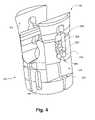
- FIG. 4is an isometric view illustrating two wedge members coupled to a tulip saddle, in a first position, according to one exemplary embodiment.
- FIGS. 5A and 5Bare respectively, side views of a wedge member coupled to a tulip saddle in a first position and a final position, according to one exemplary embodiment.
- FIG. 6is an isometric view of a tulip body, according to one exemplary embodiment.
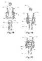
- FIG. 7Ais a cross sectional view illustrating an assembled tulip assembly comprising wedge members, a tulip body, and a tulip saddle, prior to attachment to a pedicle screw and receipt of a rod, according to one exemplary embodiment.
- FIG. 7Bis a cross section view illustrating a tulip assembly coupled to a pedicle screw in a first, partially secured, state, prior to receipt of a rod, according to one exemplary embodiment.
- FIG. 7Cis a cross sectional view illustrating a tulip assembly coupled to pedicle screw in a first, partially secured state, and a rod snapped in place in an initial unsecured state, according to one exemplary embodiment.
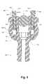
- FIG. 8is a cross sectional view illustrating a tulip assembly coupled to a pedicle screw in a second, fully secured state, and a rod snapped in place in an initial unsecured state, according to one exemplary embodiment.
- FIG. 9is a cross sectional view illustrating a tulip assembly fully securing a pedicle screw and a rod in a partially secured state, according to one exemplary embodiment.
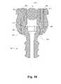
- FIG. 10is a cross sectional view illustrating an assembled tulip assembly coupled to a pedicle screw in a second, fully secured state, and a rod snapped in place in a final fully secured position, according to one exemplary embodiment.
- FIG. 11is a flowchart illustrating a method of installing a pedicle screw and subsequent securing of a rod within the tulip assembly secured to the pedicle screw, according to one exemplary embodiment.
- FIGS. 12A-12Fillustrate an exemplary process of securing a tulip assembly to a pedicle screw and subsequent securement of a rod, according to one exemplary embodiment.
- a pedicle screw and rod assemblythat has a low profile when in a final assembled position.
- the present exemplary systems and methodsprovide for a pedicle screw and rod assembly system including a rod retaining member that includes a plurality of compression wedges to fix the rod within the screw assembly.
- the rod retaining memberis approximately equal to, or lower than the rod itself. This provides a low profile pedicle screw and rod assembly since the rod itself will normally be the uppermost member of the fully locked assembly. Further details of the present system and method will be provided below.
- pedicle screw systemsmay be fixed in the spine in a posterior lumbar fusion process via minimally invasive surgery (MIS) techniques.
- MISminimally invasive surgery
- the systemsare inserted into the pedicles of the spine and then interconnected with rods to manipulate (e.g., correct the curvature, compress or expand, and/or structurally reinforce) at least portions of the spine.
- rodsto manipulate (e.g., correct the curvature, compress or expand, and/or structurally reinforce) at least portions of the spine.
- a pedicle screw system in accordance with one embodiment of the present exemplary system and methodprovides the advantage that the pedicle screw may be inserted into the bone without being pre-operatively coupled with the rod-coupling assembly (hereinafter referred to as a tulip assembly).
- a tulip assemblythe rod-coupling assembly
- Thisis advantageous because the surgeon often needs to do other inter-body work after inserting the pedicle screw, but before attaching the larger and bulkier tulip assembly.
- Such an advantageous pedicle screw systemmay be even more crucial when using MIS techniques because the inter-body spatial boundaries in which the surgeon must work may be quite limited.
- distractionwhen used herein and when used in a medical sense, generally relates to joint surfaces and suggests that the joint surfaces move perpendicular to one another. However when “traction” and/or “distraction” is performed, for example on spinal sections, the spinal sections may move relative to one another through a combination of distraction and gliding, and/or other degrees of freedom.
- tulip assemblyshould be understood to mean at least a portion of the system described herein, wherein the system comprises a tulip body ( 130 , FIG. 1 ), a tulip saddle ( 120 , FIG. 1 ), wedge members ( 110 , FIG. 1 ), and pins (not shown) for coupling the tulip saddle and the tulip body.
- FIG. 1illustrates an exploded view of one exemplary embodiment of the present system and method. It is illustrated that the present exemplary system, according to one exemplary embodiment, comprises of a distraction rod ( 100 ), at least one wedge member ( 110 ), a tulip saddle ( 120 ), a tulip body ( 130 ), and a pedicle screw ( 140 ).
- the pedicle screwis best illustrated in FIG. 1 as having a proximal end ( 160 ) and a distal end ( 170 ).
- the proximal end ( 160 )is configured with a head portion ( 155 ) and contains driving features ( 145 ).
- the shaft of the pedicle screw approaching the distal end ( 170 )is configured with a threaded portion ( 165 ), wherein the threads ( 165 ) are configured to aid in penetrating a bone and securing the pedicle screw ( 140 ) within a patient's bone.
- the pedicle screw ( 140 )may have a tip on the distal end ( 170 ) configured to facilitate easier penetration of the bone, and may also be configured to remove material as the bone is penetrated allowing the pedicle screw ( 140 ) to be inserted with no pre-drilling.
- the pedicle screw ( 140 ) as describedis one exemplary embodiment of a pedicle screw, however many variations of commonly used pedicle screws may be used with the present exemplary system and method described herein. As described in conjunction with subsequent illustrations, the pedicle screw may represent any number of pedicle screws.
- the present exemplary systemsecures a tulip assembly to a pedicle screw ( 140 ) and secures a rod ( 100 ) within the tulip assembly.
- tulip assemblycomprises a tulip body ( 130 ), a tulip saddle ( 120 ), and at least one wedge member ( 110 ), and any additional connecting elements.
- the tulip body ( 130 )(hereinafter referred to as the body) is a substantially cylindrical or circular member having a bore ( 135 ) extending from a top portion to a lower portion.
- the bore ( 135 )is configured to receive a head portion ( 155 ) of a pedicle screw ( 140 ).
- the body ( 130 )captures the head ( 155 ) of a pedicle screw ( 140 ) and while allowing rotation and angular movement, prevents release of the pedicle screw ( 140 )
- the body ( 130 )is configured to allow the head portion to pass through the bore ( 135 ) and be captured by the tulip saddle ( 120 ) (hereinafter referred to as the saddle).
- the body ( 130 )is configured to aid the saddle ( 120 ) in fully securing the head ( 155 ) of a pedicle screw ( 140 ) as well as aid in securement of a rod ( 100 ).
- the saddle ( 120 ) and the body ( 130 )are coupled to one another through slots and pins; wherein a pin is inserted through slots in both the body ( 130 ) and the saddle ( 120 ) and thereby prevents separation of the two.
- the saddle ( 120 ) and the body ( 130 )are manufactured as one piece, thereby eliminating the need for coupling members, such as pins and slots, to secure them together.
- the saddle ( 120 ) and the body ( 130 )are coupled to one another through various methods including but in no way limited to adhesives, welds, fasteners, and the like.
- a saddle ( 120 )is configured with a lower portion and an upper portion.
- the lower portioncaptures the head ( 155 ) of a pedicle screw ( 140 ) and in conjunction with a body ( 130 ) secures the pedicle screw ( 140 ) at a desired angle relative to the tulip assembly.
- the lower portion of the saddle ( 120 )is configured with expansion slots allowing the saddle ( 120 ) to expand and then contract, thereby capturing the head ( 155 ) of a pedicle screw ( 140 ).
- the upper portion of the saddle ( 120 )is configured to allow a rod ( 100 ) to be snapped into place.
- the upper portion of the saddle ( 120 ), as shown in FIG. 1 according to one exemplary embodiment,is generally a cylindrical shape, however, the outer walls may include a substantially planar portion configured to be mated with two wedge members ( 110 ).
- the saddle ( 120 )has two substantially planar sides and is configured to be mated with two wedge members ( 110 ), however it is conceivable that the saddle ( 120 ) may only have one substantially planar portion and be configured to be mated with only one wedge member ( 110 ). It is also possible that the saddle ( 120 ) may be a polygonal cylindrical tulip shape having multiple sides each configured to receive a wedge member ( 110 ).
- the substantially planar sides of the saddle ( 120 ) illustrated in FIG. 1could be replaced by a stepped surface to perform substantially the same function as the stepped outer surfaces of the wedge members ( 110 ), which function will be described in detail below.
- the wedge members ( 110 )are configured to be mated with the outside walls of the saddle ( 120 ).
- the wedge members ( 110 ), as described in greater detail below,are configured with a narrow distal end and wide proximal end.
- the saddle ( 120 ) and the body ( 130 )are configured such that a gap exists between the outer wall of the saddle ( 120 ) and the inner wall of the body ( 130 ), where the wedge members ( 110 ) are to be inserted.
- the wedge members ( 110 )are configured to be slideably coupled to the saddle ( 120 ), and according to one exemplary embodiment, have at least three positions: an initial uncompressed state, a first partially compressed state, and a final fully compressed state.
- the three statesare described as a level of compression in that when the wedge members ( 110 ) are inserted between the saddle ( 120 ) and the body ( 130 ) the wedge member's narrow distal end is configured to fill the gap between the saddle ( 120 ) and the body ( 130 ). Upon further insertion the wider portion of the wedge member ( 110 ) causes the saddle ( 120 ) to be compressed inward. Consequently, by insertion of the wedge members ( 110 ), the tulip walls of the saddle ( 120 ) are compressed inward compressing the rod ( 100 ) within a rod-receiving channel in the saddle ( 120 ). The compressive forces are sufficient to lock the rod ( 100 ) within the tulip assembly.
- the wedge members ( 110 )are slideably coupled to the outer wall of the saddle ( 120 ) through protrusions and slots.
- the slots and protrusionsfacilitate in allowing the wedge members ( 110 ) to be placed in an initial uncompressed state where the saddle ( 120 ) is not compressed at all, a first partially compressed state where the saddle ( 120 ) is compressed sufficient to prevent the rod ( 100 ) form snapping out of the saddle ( 120 ) while still allowing translation of the rod ( 100 ) within the assembly, and a final fully compressed state where the saddle ( 120 ) is compressed with enough force to fully secure the rod and prevent any movement thereof.
- FIGS. 2A and 2Billustrate the tulip saddle (the saddle) ( 120 ) through a top isometric view and a bottom isometric view, respectively according to one exemplary embodiment.
- the saddle ( 120 ) as shown in FIG. 2Ahas a proximal end ( 210 ) and a distal end ( 220 ).
- the distal endis configured to receive the head of a pedicle screw and, as illustrated, longitudinal expansion slots ( 230 ) allow the distal portion to expand to receive the head portion of a pedicle screw and subsequently contract, thereby capturing the head of the pedicle screw.
- the longitudinal slots ( 230 )allow the lower portion of the saddle ( 120 ) to expand and contract allowing the head of a pedicle screw to be snapped into place; however, according to alternative embodiments, the distal end ( 220 ) of the saddle ( 120 ) is configured with an orifice allowing the head portion of a pedicle screw to enter wherein an expansion ring is configured to expand and subsequently contract, thereby securing the head of the pedicle screw within the saddle ( 140 ).
- the lower portion near the distal end ( 220 )is configured with an opening ( 295 ) through which the head of a pedicle screw enters.
- the head portioncauses the distal end ( 220 ) of the saddle ( 120 ) to expand with the longitudinal slots ( 230 ) facilitating the expansion.
- the distal end ( 220 )contracts and thereby secures the head of the pedicle screw.
- expansion reliefs ( 240 ) in the walls of the saddle ( 120 )may be provided to allow sufficient expansion of the lower portion.
- slots ( 260 )are configured in the saddle ( 120 ) to receive a pin.
- the slotsas illustrated, are substantially elongated, however, according to various embodiments, the slots may be of any number of various shapes and sizes.
- the slots ( 260 )are configured to receive a pin, wherein the pin also passes through corresponding slots on the body ( 130 , FIGS. 1 and 6 ). With the pin in place through the slots in both the body ( 130 , FIGS. 1 and 6 ) and the saddle ( 120 , FIG. 2 ), the saddle ( 120 ) is secured to the body. According to one exemplary embodiment, with the pins in place, the saddle ( 120 ) and body ( 130 , FIGS.
- FIG. 2Aalso illustrates the rod-receiving channel ( 270 ) of the saddle ( 120 ).
- a rodmay be snapped within the channel.
- two protrusions ( 280 ) on each side of the channelprovide resistance for the rod to enter and exit. Consequently, when a rod is placed within the channel, the protrusions ( 280 ) cause the rod to force a slight expansion of the saddle ( 120 ). Once the rod is within the channel ( 290 ) the saddle ( 120 ) contracts again. The rod is effectively snapped in and out of the channel ( 290 ).
- the outer walls of the saddle ( 120 )are substantially flat or planar and are configured to assist in coupling wedge members ( 110 , FIG. 1 ) to the saddle ( 110 ).
- the outer walls of the saddle ( 120 )may be stepped to further enhance or replace the effect of the wedge members ( 110 ; FIG. 1 ).
- the saddle ( 120 )is formed with protrusions ( 250 ) configured to be mated with the slot in a wedge member ( 110 , FIG. 1 ).
- FIG. 3further illustrates a tulip saddle ( 120 ), according to one exemplary embodiment, and wedge members ( 110 ) that are configured to be mated with the saddle ( 120 ).
- the saddle ( 120 )is configured with a flat outer wall ( 370 ) that is mated with the flat inner wall ( 350 ) of a wedge member ( 110 ).
- the outer wall ( 360 ) of the wedge membersis substantially rounded and is configured to interact with the inner wall of the body ( 130 , FIGS. 1 and 6 ).
- the saddleis further configured with a stop ( 390 ); the stop ( 390 ) is configured to prevent a wedge member ( 110 ) from being inserted further than is desired.
- both the flat outer wall ( 370 ) and the flat inner wall ( 350 )may be stepped or tapered to enhance or replace the wedging effect provided by the wedge members, as detailed below.
- the saddle ( 120 ), as illustrated in FIG. 3is formed with a protrusion ( 250 ) configured to interact with the longitudinal slot ( 330 ) in the wedge members ( 110 ).
- the wedge members ( 110 )have a distal end ( 302 ) and a proximal end ( 301 ).
- the distal end ( 302 ) of the wedge members ( 110 )is relatively thin from the flat inner wall ( 350 ) to the rounded outer wall ( 360 ), while the proximal end ( 301 ) is relatively thick from the inner wall ( 350 ) to the outer wall ( 360 ).
- the varying profile of the wedge members ( 110 )creates a wedge shape that upon insertion causes the saddle ( 120 ) to compress.
- the longitudinal slot ( 330 ) in the wedge members ( 110 )is configured with a varying profile as illustrated in FIG. 3 .
- the profile of the slotincludes, according to one exemplary embodiment, an entrance diameter ( 310 ) that is narrower than the width of the protrusions ( 250 ) on the saddle, a first position ( 320 ) in which the width is substantially identical to that of the protrusions ( 250 ), a channel ( 330 ) in which the width is substantially identical to that of the protrusions ( 250 ).
- a wedge member ( 110 )has a longitudinal slot ( 330 ) configured to be mated with a protrusion ( 250 ) of a saddle ( 120 ), enabling them to be coupled together in multiple positions.
- the wedge members ( 110 )may be coupled to the saddle ( 120 ) by the protrusion ( 250 ) on the saddle and the slot ( 330 ) in the wedge members ( 110 ), as illustrated in FIG. 4 .
- the wedge members ( 110 )are configured with a flat or planar side ( 350 ) that corresponds to the flat or substantially planar outer wall ( 370 ) of the saddle ( 120 ).
- FIG. 4illustrates the wedge members ( 110 ) coupled to the saddle ( 120 ).
- the protrusion ( 250 )is in the first position ( 320 ) of the longitudinal slots ( 330 ) of the wedge members ( 110 ).
- the wedge members ( 110 )may be slid further down the side of the saddle ( 120 ).
- the protrusions ( 250 )enter the channel ( 330 ) and ultimately advance to the final position ( 340 ).
- the lower portion ( 380 ) of the wedge members ( 110 )will contact the stop ( 390 ) of the saddle ( 120 ) as the protrusion ( 250 ) enters the final slot position ( 340 ).
- FIGS. 5A and 5Bare side views of the coupling action.
- FIG. 5Ais a side view showing the connection substantially identical of that shown in FIG. 4 , wherein the wedge member ( 110 ) is coupled to the saddle ( 120 ) with the protrusion ( 250 ) of the saddle ( 120 ) in the first position ( 320 , FIG. 4 ) of the wedge member ( 110 ).
- Arrows ‘F’are shown in FIG. 5A to illustrate that a downward force on the wedge members ( 110 ) will cause the assembly to proceed from that of FIG. 5A to that of FIG. 5B , in which the wedge members ( 110 ) are shown fully inserted.
- FIG. 5Billustrates the wedge members ( 110 ) in a final state, wherein the protrusion ( 250 ) of the saddle ( 120 ) is in a final position ( 340 , FIG. 4 ). It is also of note that the lower portion ( 380 ) of the wedge members ( 110 ) has contacted the stop ( 390 ) of the saddle ( 120 ).
- the channel ( 290 , FIG. 2 )is in a relatively uncompressed state, with the protrusion ( 250 ) in the first position ( 320 , FIG. 4 ).
- the channel ( 290 , FIG. 2 )is in a fully compressed state, with the protrusion ( 250 ) in a final position ( 340 , FIG. 4 ).
- the channel ( 290 , FIG. 2 )may be placed in a partially compressed state by maintaining the protrusion ( 250 ) within the longitudinal slot ( 330 ) of the wedge members ( 110 ) between the first position ( 320 , FIG. 4 ) and the final position ( 340 , FIG. 4 ).
- the compression of the channel ( 290 , FIG. 2 )is caused, at least in part, by the wedge members ( 110 ) being inserted between the saddle ( 120 ) and the body ( 130 , FIGS. 1 and 6 ) as will be described in greater detail below.
- the body ( 130 )Prior to the details of the interaction of the wedge members ( 110 ) and saddle ( 120 ) and the body ( 130 ), we briefly examine the body ( 130 ) as illustrated according to one exemplary embodiment in FIG. 6 .
- the importance of the bodyis in both the securement of the head of a pedicle screw and the securement of a rod within the tulip assembly.
- the body ( 130 )is substantially cylindrical with tulip walls defining a channel wherein a rod may be placed.
- the body ( 130 )has a through bore extending from the proximal end ( 610 ) to the distal end ( 620 ) configured to receive a saddle ( 120 , FIG. 1 ).
- the securement of the body ( 130 ) to the saddle ( 120 )may be accomplished, according to one exemplary embodiment, by inserting pins through slots (not shown) in the body ( 130 ) and into slots ( 260 , FIG. 2 ) in the saddle ( 120 , FIG. 2 ).
- the bodyis configured with a varying inner diameter, wherein the inner diameter is configured to interact with a saddle to capture and secure the head of a pedicle screw.
- FIG. 7Ais a cross sectional view of a tulip assembly comprising a body ( 130 ), a saddle ( 120 ), and wedge members ( 110 ) prior to attachment of a pedicle screw ( 140 ) and insertion of a rod ( 100 ), according to one exemplary embodiment.
- the tulip assemblyis fully constructed prior to attachment to a pedicle screw ( 140 ) and prior to insertion of a rod ( 100 ), according to one exemplary embodiment.
- the order of coupling the saddle ( 120 ) to the body ( 130 ), coupling the wedge members ( 110 ) to the saddle ( 120 ), snapping a rod ( 100 ) within the channel ( 290 ) of the saddle ( 120 ), and capturing the head ( 155 ) of a pedicle screw ( 140 )may be performed in any order desired.
- the saddle ( 120 )has an opening ( 295 ) configured to receive the head ( 155 ) of a pedicle screw ( 140 ).
- the opening ( 295 )has an entrance diameter ( 705 ) smaller than the diameter of the head ( 155 ) of the pedicle screw ( 140 ). Consequently, when the head ( 155 ) is inserted into the opening ( 295 ), the entrance diameter ( 705 ) of the saddle ( 120 ) is forced to expand and receive the head ( 155 ).
- the expansion of the saddle ( 120 )is aided by longitudinal slots ( 230 , FIG. 2 ) and expansion reliefs ( 240 , FIG. 2 ) previously described herein.
- the entrance diameter ( 705 )retracts and the head ( 155 ) of the pedicle screw ( 140 ) is captured within the opening ( 295 ) with the widest diameter of the head ( 155 ) corresponding to the middle diameter ( 710 ) of the opening ( 295 ).
- the middle diameter ( 710 )is approximately the same diameter as the widest diameter of the head ( 155 ) of the pedicle screw ( 140 ).
- the middle diameter ( 710 )may be slightly smaller than the widest diameter of the head ( 155 ) of the pedicle screw ( 140 ) in order to provide some slight friction that may aid in maintaining the relative position of the saddle ( 120 ) relative to the pedicle screw prior to locking of the assembly.
- FIG. 7Billustrates the tulip assembly after the pedicle screw ( 140 ) as been successfully snapped into place, according to one exemplary embodiment.
- the wedge members ( 110 )are in the first position, wherein the saddle is in a relatively uncompressed state. The first position of the wedge members is described in detail above in reference to FIGS. 5A and 5B .
- FIG. 7Billustrates the tulip assembly, according to one exemplary embodiment, coupled to a pedicle screw ( 140 ) and prepared for reception of a rod ( 100 ).
- FIG. 7Cillustrates the tulip assembly of FIGS. 7A and 7B after a rod ( 100 ) has been snapped into place.
- the rodis snapped into place due to the resistance provided by protrusions ( 280 , FIG. 2 ) extending inward from the walls of the saddle ( 120 ).
- the rod ( 100 )is free to be snapped in and out of the assembly and may also be translated longitudinally through the channel ( 290 , FIG. 2 ), as the wedge members ( 110 ) are in a first position as in FIG. 5A .
- the lower portion ( 720 ) of the saddle ( 120 )is configured to interact with a lower portion ( 730 ) of the inner wall of the body ( 130 ).
- the lower portion ( 720 ) of the saddle ( 120 )is not in compressive contact with the lower portion ( 730 ) of the body ( 130 ). Consequently, the head ( 155 ) of the pedicle screw ( 140 ) is captured in a partially secured sate as described above.
- both the lower portions ( 720 , 730 ) of the saddle ( 120 ) and the body ( 130 )are forced together.
- the lower portion ( 730 ) of the body ( 130 )causes the lower portion ( 720 ) of the saddle ( 120 ) to compress the head ( 155 ) of the pedicle screw ( 140 ) and thereby create and interference fit locking the pedicle screw ( 140 ) in place. This can be seen, according to one exemplary embodiment, in FIG. 8 .
- FIG. 8is a tulip assembly similar to those of FIGS. 7A-C in that the tulip assembly is fully assembled, a rod ( 100 ) is snapped in the channel ( 290 , FIG. 2 ), and the tulip assembly has captured the head ( 155 ) of a pedicle screw ( 140 ).
- FIG. 8illustrates that the saddle ( 120 ) has been forced down fully into the body ( 130 ), thereby causing the lower members ( 720 , 730 ) to contact one another and compress the lower member ( 720 ) of the saddle ( 120 ).
- the compressive forcesare configured to be sufficient to lock the head ( 155 ) of the pedicle screw ( 140 ) within the tulip assembly and prevent any motion thereof.
- the wedge members ( 110 ) as illustrated in FIG. 8are in a first position, as described in conjunction with FIG. 5A , in which the rod is free to be snapped in and out or be translated longitudinally.
- FIG. 9illustrates a tulip assembly, rod ( 100 ), and pedicle screw ( 140 ) similar to those previously described with the wedge members ( 110 ) partially inserted.
- the wedge members ( 110 )are substantially thicker on the proximal end ( 301 ) than on the distal end ( 302 ).
- the wedge members ( 110 )are coupled to the saddle ( 120 ) as described in conjunction with FIG. 4 . While the wedge members ( 110 ) in FIG. 8 are shown in a first fully uncompressed state, FIG.
- FIG. 9illustrates the wedge members ( 110 ) partially inserted with the thicker proximal end ( 301 ) entering the space between the saddle ( 120 ) and the body ( 130 ).
- the wedge members ( 110 )are not fully inserted into a final fully compressed state, but are rather in a partially compressive state as described above.
- the partial insertion of the wedge members ( 110 )cause the walls of the saddle ( 120 ) to be compressed inward, resulting in compression of the channel ( 290 , FIG. 2 ). Consequently, in the partially compressed state of FIG. 9 , the channel ( 290 , FIG.
- the rod illustrated in FIG. 9is still free to be translated longitudinally within the tulip assembly.
- FIG. 10is a tulip assembly in a fully locked state, according to one exemplary embodiment.
- a primary advantage of the system and method herein describedis that the resulting tulip assembly in a final locked state has a low profile.
- the uppermost portion of the assemblymay be functional while assuming any height, depending on the height of the individual components
- one exemplary embodiment of the present exemplary systemincludes an embodiment wherein the uppermost portion of the assembly is parallel with or lower than the uppermost surface the rod ( 100 ).
- FIG. 10illustrates the wedge members ( 110 ) fully inserted and in a final position as described above in conjunction with FIG. 5B .
- the fully inserted wedge members ( 110 )create an interaction between the relatively wide proximal ends ( 301 ) of the wedge members ( 110 ) and the walls of the saddle ( 120 ), forcing the walls of the saddle ( 120 ) inward causing the channel ( 290 , FIG. 2 ) to be fully compressed.
- the compressive forces caused by the wedge members ( 110 )are sufficient to cause the rod ( 100 ) to be locked in an interference fit within the channel ( 290 , FIG. 2 ).
- the rod ( 100 )is fully locked and is prevented from both snapping out of the channel and from translation within the channel.
- the saddle ( 120 )has been forced down fully into the body ( 130 ).
- FIG. 11is a flow chart illustrating an exemplary method for installing a pedicle screw, coupling a tulip assembly, and securing a rod within the tulip assembly, according to one exemplary embodiment. It should be understood that the following description in conjunction with FIG. 11 is provided as an example of a method of use according to one exemplary embodiment and that many modification of the method are possible, including a rearranging of the steps, elimination of steps, or the inclusion of additional intermediate steps, all of which are not only possible, but highly likely. For ease in describing the present exemplary system and method only, the present exemplary method is described in the context of a previously un-assembled tulip member. However, any number of components of the present exemplary system may be pre-assembled prior to insertion into a patient. All numerical references are with respect to FIG. 1 while step references are with respect to FIG. 11 , unless otherwise noted.
- Step 1The insertion of a pedicle screw into a patient's bone (Step 1 ) for subsequent coupling of a rod is common in medical practice and is well understood in the prior art. Often a bone screw is inserted into one or more vertebrae and rods coupling each bone screw act to support the vertebrae and/or prevent movement thereof. As illustrated in FIG. 1 , driving features ( 145 ) on the head ( 155 ) of a pedicle screw ( 140 ) may be utilized to drive the pedicle screw ( 140 ) into the patient's bone. However, it is within the scope of this disclosure to use various pedicle screws, bone screws, or other anchoring devices as deemed appropriate.
- the tulip body ( 130 )may be positioned over the head ( 155 ) of the bone screw ( 140 ) by passing the head ( 155 ) through the bore (Step 2 ).
- the saddle ( 120 )may be coupled to the body ( 130 ) and the head ( 155 ) of the pedicle screw may be captured within the saddle ( 130 ).
- the saddle ( 120 ) and the body ( 130 )may be coupled first and then snapped onto the head ( 155 ) of a pedicle screw ( 140 ).
- the saddle ( 120 ) and the body ( 130 )may be manufactured as a single element, wherein a portion of the single element is configured to be slidable with respect to the other portion and perform the functions of the saddle ( 120 ) described herein.
- a rod ( 100 )may be snapped (Step 4 ) into the channel ( 290 , FIG. 2 ) of the saddle ( 120 ).
- the rod ( 100 )is snapped into place prior to the wedge members ( 110 ) being placed and coupled to the saddle ( 120 ), according to one exemplary embodiment.
- the saddle ( 120 )may have initially been coupled to the body ( 130 ) to partially capture the head ( 155 ) of the pedicle screw ( 140 ), as described in Step 3 .
- lower portions ( 720 , 730 ) of both the saddle and bodyinteract to cause the lower portion ( 720 ) of the saddle ( 120 ) to compress the head of the pedicle screw sufficient to lock a relative angle (Step 5 ) between the tulip assembly and the pedicle screw ( 140 ).
- Step 5a relative angle
- Inserting the wedge members ( 110 ) into a first uncompressed statewill not secure the rod. Consequently, insertion of the wedge members ( 110 ) may be performed in situ or prior to insertion at any time prior to Step 6 .
- a downward force on the wedge members ( 110 )will cause them to enter partially between the saddle ( 120 ) and the body ( 130 ). This will, as described above, cause a force on the walls of the saddle ( 120 ) to compress the channel ( 290 , FIG. 2 ) and thereby create an interference fit with the rod ( 100 ).
- the channel ( 290 , FIG. 2 )is compressed sufficiently to prevent the rod ( 100 ) from snapping out, while still allowing the rod ( 100 ) to translate longitudinally within the channel.
- the rod ( 100 )may be fully locked within the tulip assembly by forcing the wedge members ( 110 ) down completely (Step 7 ).
- the complete assemblyis described as a low profile pedicle screw assembly because the upper most portions of the tulip assembly are parallel with or lower than the upper most portion of the rod ( 100 ).
- FIGS. 12A-Fprovide an illustration of the foregoing exemplary method.
- the figuresare intended to represent one exemplary method, as such it should be understood that the order may be modified or steps may be combined, omitted, or added as deemed necessary without straying from the spirit of the exemplary method.
- FIGS. 12A-Fare, according to various exemplary embodiments, alternative embodiments described and those modifications that may be obvious due to the teachings and disclosures provided herein may not be fully represented by the figures.
- FIG. 12Aillustrates the tulip assembly comprising two wedge members ( 110 ), a saddle ( 120 ), and a body ( 130 ) coupled to one another prior to securement of a screw head ( 155 ) and prior to the capture of a rod ( 100 ).
- FIG. 12Billustrates the initial capture of the head of a screw. As illustrated, the pedicle screw ( 140 ) is captured within the saddle ( 120 ). However, the saddle ( 120 ) is free to pivot around the head, as it has not been fully locked, corresponding to Step 3 of FIG. 11 .
- FIG. 12Cillustrates the subsequent capture of a rod ( 100 ), according to one exemplary embodiment. As can be seen in FIG. 12C , the rod ( 100 ) effectively snaps into the channel ( 290 , FIG. 7A ), corresponding to Step 4 of FIG. 11 .
- FIG. 12Dillustrates the fully locked head of a screw ( 140 ) within the saddle ( 120 ). As shown the tulip assembly is locked with no relative angle; however, as previously disclosed the tulip assembly may be locked at a desired angle relative to the screw ( 140 ).
- FIG. 12Dcorresponds to Step 5 of FIG. 11 .
- FIG. 12Eillustrates the wedge members ( 110 ) partially inserted, wherein the insertion is to the point of partially locking a rod ( 100 ) within the saddle ( 120 ). That is, the rod ( 100 ) is prevented from snapping out, while still free to translate longitudinally.
- FIG. 12Ecorresponds to Step 6 of FIG. 11 .
- FIG. 12Fillustrates the wedge members ( 110 ) fully inserted.
- Thisis an illustration of the completely installed system, according to one exemplary embodiment.
- the uppermost portion of the assemblyis the rod ( 100 ) itself. This allows for a low profile system, advantageous in MIS techniques.
- the rod ( 100 )is fully secured within the saddle and the tulip assembly is fully secured to the head of the screw ( 140 ), corresponding to Step 7 of FIG. 11 .
- various members of the tulip assemblymay be anodized, painted, varied in surface finish, or in other manners common in the art configured with various colors. According to one embodiment, by coloring various members of the tulip assembly or even various faces of the members of the tulip assembly, a person installing the system would be able to visually ascertain the state of securement the system is in by which colors are viewable.
- the top most face ( 399 ) of the wedge members ( 110 )might be colored, for example silver, the same as the other portions of the tulip assembly including the body ( FIG. 6 , 130 ) and the saddle ( FIG. 3 , 120 ), while the flat inner face ( 350 ) and the rounded outer face ( 360 ) might be colored a distinct color from the rest of the system, for example blue. Consequently, when the wedge members ( 110 ) are inserted in a first initial state, as shown in FIG. 8 , a majority of the system would be silver. However, both the flat inner face ( 350 ) and the rounded outer face ( 360 ) of both wedge members ( 110 ) would display a distinct blue color, alerting the surgeon that the system is not in a fully secured state.
- the flat inner face ( 350 ) and the rounded outer face ( 360 ) of the wedge members ( 110 )are within the tulip assembly and are not visible to the surgeon. Only the upper face ( 399 ) that is colored silver, similar to the other portions of the tulip assembly, is visible; consequently when the wedge members are fully inserted as in FIG. 10 , and the system is in a fully secured state, only the color silver will be visible, the lack of the color blue would indicate that the system is fully locked.
- the wedge members ( 110 )may include a top face ( 399 ) colored one color, for example silver; the top half of the wedge members ( 110 ) on both the inner flat face ( 350 ) and the outer rounded face ( 360 ) colored another color, for example blue; and the bottom half of the wedge members ( 110 ) on both the inner flat face ( 350 ) and the outer rounded face ( 360 ) colored a third color, for example red; where the other portions of the tulip assembly are neither red nor blue.
- the wedge members ( 110 )are in an initial uncompressed state, as in FIG. 8 , the surgeon will see both red and blue, indicating that the system is completely unsecured.
- the interior surface of the saddle ( 120 )is contoured in order to apply high compression forces on both the rod ( 100 ) and the head ( 155 ) of the pedicle screw ( 140 ) ensuring that all members are retained in a fixed position.
- the amount of compression and the relative location of the compressioncan be selected according to desired design by selection of the shape, taper, and relative contour of the interior of the body ( 130 ) or the exterior surfaces of the saddle ( 120 ) relative to each other and also the contour of the wedge members ( 110 ).
- FIG. 10a cross sectional view of a completed pedicle screw ( 140 ), tulip assembly, and rod ( 100 ) is depicted.
- the top of the body ( 130 ), the saddle ( 120 ) and the wedge members ( 110 )are pressed downward until the top surfaces are flush with or even slightly recessed below the top surface of the rod ( 100 ).
- the uppermost portion of the rod ( 100 )is approximately adjacent to the uppermost portion of the tulip assembly. In one embodiment, the uppermost portions are approximately equal to each other. In alternative embodiments, the uppermost portion of the tulip assembly may be slightly lower so that the rod ( 100 ) is somewhat higher.
- the present exemplary pedicle screw systems and methodsprovide a number of exemplary connection members and methods that can be used for percutaneous screw placement.
- the present exemplary systems and methodsprovide for a low profile pedicle screw and tulip assembly that limits the size of the tulip and eliminates a need for a cap or other top structure.
- the assemblycan be configured such that the tulip is even with or lower than the top of the rod when fully locked. The resulting low profile of the present exemplary pedicle screw and tulip assembly results in less tissue damage and irritation in and around the surgical site, when compared to traditional systems.
Landscapes
- Health & Medical Sciences (AREA)
- Orthopedic Medicine & Surgery (AREA)
- Life Sciences & Earth Sciences (AREA)
- Neurology (AREA)
- Surgery (AREA)
- Heart & Thoracic Surgery (AREA)
- Engineering & Computer Science (AREA)
- Biomedical Technology (AREA)
- Nuclear Medicine, Radiotherapy & Molecular Imaging (AREA)
- Medical Informatics (AREA)
- Molecular Biology (AREA)
- Animal Behavior & Ethology (AREA)
- General Health & Medical Sciences (AREA)
- Public Health (AREA)
- Veterinary Medicine (AREA)
- Surgical Instruments (AREA)
Abstract
Description
- This application is a continuation-in-part application of U.S. patent Ser. No. 11/440,549 filed May 25, 2006 and titled “Low Profile Pedicle Screw and Rod Assembly”, which application claims the benefit under 35 U.S.C. §119(e) of U.S. Provisional Patent Application No. 60/684,695 filed May 25, 2005 and also titled “Low Profile Pedicle Screw and Rod Assembly.” Furthermore, the present application claims the benefit under 35 U.S.C. § 119(e) of U.S. Provisional Patent Application No. 60/928,150 filed May 7, 2007, titled “Low Rider Pedicle Screw System Including Restraint Features.” The above-mentioned applications are incorporated herein by reference in their entireties.
- The present exemplary system and method relates to medical devices. More particularly, the present exemplary system and method relates to pedicle screw and rod combinations that have a low profile when finally assembled.
- Various devices for internal fixation of bone segments in the human or animal body are known in the art. One type of system is a pedicle screw system, which may be used as an adjunct to spinal fusion surgery, and which provides a means of gripping a spinal segment. This is particularly used within the fields of orthopedic surgery and neurosurgery, in which spinal implants and rods hold vertebral members in position relative to one another.
- A conventional pedicle screw system comprises a pedicle screw and a rod-receiving device. Two such systems are inserted into respective vertebrae and adjusted to distract and/or stabilize a spinal column, for instance during an operation to correct a herniated disk. The pedicle screw does not, by itself, fixate the spinal segment, but instead operates as an anchor point to receive the rod-receiving device, which in turn receives the rod. One goal of such a system is to substantially reduce and/or prevent relative motion between the spinal segments that are being fused.
- Although conventional prior art pedicle screw systems exist, they lack features that enhance and/or benefit newer, minimally invasive surgery (MIS) techniques that are more commonly being used for spinal surgeries. It has been suggested that one possible advantage of an MIS approach is that it can increase a patient's rate of recovery.
- Conventional pedicle screw systems and even more recently designed pedicle screw systems have several drawbacks. Some of these pedicle screw systems are rather large and bulky, which may result in more tissue damage in and around the surgical site when the pedicle screw system is installed during surgery. Traditional pedicle screw systems have a rod-receiving device that is pre-operatively coupled or attached to the pedicle screw. In addition, some of the prior art pedicle screw systems include numerous components that must all be carefully assembled together. Further, traditional pedicle screw systems are pre-operatively assembled, which makes these systems more difficult to install and maneuver in a spinal operation where MIS techniques are used.
- In one of many possible embodiments, a pedicle screw and rod assembly is provided which has a low profile in the final assembled position. The pedicle screw includes a screw having a threaded portion and a head portion. A tulip body (the body) is positioned on the head portion of the screw. A tulip saddle (the saddle) is coupled to the body and is configured to retain the head portion of the pedicle screw secured to the body and saddle. Wedge members are configured to be inserted between the body and the saddle; the varying profile of the wedge members, when inserted, compress the saddle and secure a rod within a rod-receiving channel of the saddle. The top of the wedge members, saddle and body are relatively flush and are approximately equal to, or lower than the uppermost portion of the rod. This provides a low profile pedicle screw and rod assembly since the rod itself will be at least part of the uppermost member of the completed assembly.
- According to one exemplary embodiment, the saddle is snapped onto the head portion of a pedicle screw, where it retains the pedicle screw in a partially secured state. In addition, to the saddle coupling the head of the pedicle screw, the body acts to further aid in securement of the pedicle screw. The saddle is coupled to the body, preventing separation of the two components; according to one exemplary embodiment, the saddle is configured with slots allowing pins to secure the saddle to the body, which is configured with corresponding slots or pin-receiving components. According to one exemplary embodiment, the tulip saddle and the tulip body may be coupled together by pins. The body and the saddle, in conjunction, secure the head of a pedicle screw in two positions. A first position in which the head is secured from release, while still free to rotate and pivot, and a second position in which the head is fully secured; that is, an angular position is locked securing the tulip assembly and the pedicle screw at a desired angle.
- According to yet another exemplary embodiment, once the saddle and body are coupled, a rod may be snapped into a rod-receiving channel within the saddle. The rod may be snapped in and out as desired, and may translate longitudinally as well. Wedge members are configured to be coupled to at least one side of the tulip saddle, and according to one exemplary embodiment, the saddle is configured to be mated with two wedge members, one on each side. Corresponding intrusions and protrusions on the wedge members and the tulip saddle are configured to retain the wedge members in several positions. According to one exemplary embodiment, the wedge members are of a varying profile, a first narrower portion and a second wider portion. As the wedge member is inserted between the tulip saddle and the tulip body, the wedge member may be coupled by the previously mentioned intrusions and protrusions to the saddle, while not yet acting to compress the saddle. As the wedge members are inserted to a first securing position, according to one exemplary embodiment, the saddle is compressed and partially secures the rod; the rod is free to translate within the rod-receiving channel of the saddle, but is prevented from snapping in and out of the channel. In another wedge member position, fully inserted, the wedge members, the tulip saddle, and the tulip body, sit flush with one another and sit even with or lower than the top of the rod. In this second fully inserted position, the wedge members compress the tulip saddle and thereby secure the rod within the channel completely, preventing the rod from movement. According to one exemplary embodiment, the wedge members are colored in such a way so as to assist the surgeon in determining the state of the tulip assembly.
- The accompanying drawings illustrate various embodiments of the present system and method and are a part of the specification. The illustrated embodiments are merely examples of the present system and method and do not limit the scope thereof.
FIG. 1 is an exploded view showing several of the components of a pedicle screw assembly, according to one exemplary embodiment.FIGS. 2A and 2B are respectively, a top isometric view and a bottom isometric view of a tulip saddle, according to one exemplary embodiment.FIG. 3 is an exploded isometric view illustrating wedge members and a tulip saddle, according to one exemplary embodiment.FIG. 4 is an isometric view illustrating two wedge members coupled to a tulip saddle, in a first position, according to one exemplary embodiment.FIGS. 5A and 5B are respectively, side views of a wedge member coupled to a tulip saddle in a first position and a final position, according to one exemplary embodiment.FIG. 6 is an isometric view of a tulip body, according to one exemplary embodiment.FIG. 7A is a cross sectional view illustrating an assembled tulip assembly comprising wedge members, a tulip body, and a tulip saddle, prior to attachment to a pedicle screw and receipt of a rod, according to one exemplary embodiment.FIG. 7B is a cross section view illustrating a tulip assembly coupled to a pedicle screw in a first, partially secured, state, prior to receipt of a rod, according to one exemplary embodiment.FIG. 7C is a cross sectional view illustrating a tulip assembly coupled to pedicle screw in a first, partially secured state, and a rod snapped in place in an initial unsecured state, according to one exemplary embodiment.FIG. 8 is a cross sectional view illustrating a tulip assembly coupled to a pedicle screw in a second, fully secured state, and a rod snapped in place in an initial unsecured state, according to one exemplary embodiment.FIG. 9 is a cross sectional view illustrating a tulip assembly fully securing a pedicle screw and a rod in a partially secured state, according to one exemplary embodiment.FIG. 10 is a cross sectional view illustrating an assembled tulip assembly coupled to a pedicle screw in a second, fully secured state, and a rod snapped in place in a final fully secured position, according to one exemplary embodiment.FIG. 11 is a flowchart illustrating a method of installing a pedicle screw and subsequent securing of a rod within the tulip assembly secured to the pedicle screw, according to one exemplary embodiment.FIGS. 12A-12F illustrate an exemplary process of securing a tulip assembly to a pedicle screw and subsequent securement of a rod, according to one exemplary embodiment.- In the drawings, identical reference numbers identify similar elements or acts. The sizes and relative positions of elements in the drawings are not necessarily drawn to scale. For example, the shapes of various elements and angles are not drawn to scale, and some of these elements are arbitrarily enlarged and positioned to improve drawing legibility. Further, the particular shapes of the elements as drawn, are not intended to convey any information regarding the actual shape of the particular elements, and have been solely selected for ease of recognition in the drawings. Throughout the drawings, identical reference numbers designate similar but not necessarily identical elements.
- The present specification provides a number of exemplary connection members and methods that can be used for any number of orthopedic rod placement systems. According to the present exemplary system and method, a pedicle screw and rod assembly is provided that has a low profile when in a final assembled position. Specifically, the present exemplary systems and methods provide for a pedicle screw and rod assembly system including a rod retaining member that includes a plurality of compression wedges to fix the rod within the screw assembly. According to one exemplary embodiment, the rod retaining member is approximately equal to, or lower than the rod itself. This provides a low profile pedicle screw and rod assembly since the rod itself will normally be the uppermost member of the fully locked assembly. Further details of the present system and method will be provided below.
- By way of example, pedicle screw systems may be fixed in the spine in a posterior lumbar fusion process via minimally invasive surgery (MIS) techniques. The systems are inserted into the pedicles of the spine and then interconnected with rods to manipulate (e.g., correct the curvature, compress or expand, and/or structurally reinforce) at least portions of the spine. Using the MIS approach to spinal fixation and/or correction surgery has been shown to decrease a patient's recovery time and reduce the risks of follow-up surgeries.
- The ability to efficiently perform spinal fixation and/or correction surgeries using MIS techniques with minimal tissue damage is enhanced by the use of pedicle screw systems provided in accordance with the present exemplary systems and methods, which systems and methods provide a number of advantages over conventional systems. For example, a pedicle screw system in accordance with one embodiment of the present exemplary system and method provides the advantage that the pedicle screw may be inserted into the bone without being pre-operatively coupled with the rod-coupling assembly (hereinafter referred to as a tulip assembly). This is advantageous because the surgeon often needs to do other inter-body work after inserting the pedicle screw, but before attaching the larger and bulkier tulip assembly. Such an advantageous pedicle screw system may be even more crucial when using MIS techniques because the inter-body spatial boundaries in which the surgeon must work may be quite limited.
- The term “distraction,” when used herein and when used in a medical sense, generally relates to joint surfaces and suggests that the joint surfaces move perpendicular to one another. However when “traction” and/or “distraction” is performed, for example on spinal sections, the spinal sections may move relative to one another through a combination of distraction and gliding, and/or other degrees of freedom.
- In the following description, certain specific details are set forth in order to provide a thorough understanding of various embodiments of the present percutaneous pedicle screw system. However, one skilled in the relevant art will recognize that the present exemplary system and method may be practiced without one or more of these specific details, or with other methods, components, materials, etc. In other instances, well-known structures associated with pedicle screws have not been shown or described in detail to avoid unnecessarily obscuring descriptions of the embodiments of the systems and methods.
- Unless the context requires otherwise, throughout the specification and claims which follow, the word “comprise” and variations thereof, such as, “comprises” and “comprising” are to be construed in an open, inclusive sense, that is as “including, but not limited to.”
- Reference in the specification to “one embodiment” or “an embodiment” means that a particular feature, structure, or characteristic described in connection with the embodiment is included in at least one embodiment. The appearance of the phrase “in one embodiment” in various places in the specification are not necessarily all referring to the same embodiment. Furthermore, the particular features, structures, or characteristics may be combined in any suitable manner in one or more embodiments.
- Throughout the description the term tulip assembly should be understood to mean at least a portion of the system described herein, wherein the system comprises a tulip body (130,
FIG. 1 ), a tulip saddle (120,FIG. 1 ), wedge members (110,FIG. 1 ), and pins (not shown) for coupling the tulip saddle and the tulip body. FIG. 1 illustrates an exploded view of one exemplary embodiment of the present system and method. It is illustrated that the present exemplary system, according to one exemplary embodiment, comprises of a distraction rod (100), at least one wedge member (110), a tulip saddle (120), a tulip body (130), and a pedicle screw (140). The pedicle screw is best illustrated inFIG. 1 as having a proximal end (160) and a distal end (170). The proximal end (160) is configured with a head portion (155) and contains driving features (145). The shaft of the pedicle screw approaching the distal end (170) is configured with a threaded portion (165), wherein the threads (165) are configured to aid in penetrating a bone and securing the pedicle screw (140) within a patient's bone. The pedicle screw (140) may have a tip on the distal end (170) configured to facilitate easier penetration of the bone, and may also be configured to remove material as the bone is penetrated allowing the pedicle screw (140) to be inserted with no pre-drilling. The pedicle screw (140) as described is one exemplary embodiment of a pedicle screw, however many variations of commonly used pedicle screws may be used with the present exemplary system and method described herein. As described in conjunction with subsequent illustrations, the pedicle screw may represent any number of pedicle screws.- A method of using and installing the present system will be described in greater detail below; however, to better understand the structure as shown in
FIG. 1 a brief explanation is provided. The present exemplary system secures a tulip assembly to a pedicle screw (140) and secures a rod (100) within the tulip assembly. Where the term “tulip assembly” comprises a tulip body (130), a tulip saddle (120), and at least one wedge member (110), and any additional connecting elements. The tulip body (130) (hereinafter referred to as the body) is a substantially cylindrical or circular member having a bore (135) extending from a top portion to a lower portion. The bore (135) is configured to receive a head portion (155) of a pedicle screw (140). According to one exemplary embodiment, the body (130) captures the head (155) of a pedicle screw (140) and while allowing rotation and angular movement, prevents release of the pedicle screw (140) - According to another exemplary embodiment, as illustrated in
FIG. 1 , the body (130) is configured to allow the head portion to pass through the bore (135) and be captured by the tulip saddle (120) (hereinafter referred to as the saddle). The body (130), according to one exemplary embodiment, is configured to aid the saddle (120) in fully securing the head (155) of a pedicle screw (140) as well as aid in securement of a rod (100). According to one exemplary embodiment, the saddle (120) and the body (130) are coupled to one another through slots and pins; wherein a pin is inserted through slots in both the body (130) and the saddle (120) and thereby prevents separation of the two. According to an alternative embodiment, the saddle (120) and the body (130) are manufactured as one piece, thereby eliminating the need for coupling members, such as pins and slots, to secure them together. According to various embodiments, the saddle (120) and the body (130) are coupled to one another through various methods including but in no way limited to adhesives, welds, fasteners, and the like. - As illustrated in
FIG. 1 , and as will be described in greater detail in conjunction with subsequent drawings, a saddle (120) is configured with a lower portion and an upper portion. The lower portion captures the head (155) of a pedicle screw (140) and in conjunction with a body (130) secures the pedicle screw (140) at a desired angle relative to the tulip assembly. According to one exemplary embodiment, as will be delineated in greater detail below, the lower portion of the saddle (120) is configured with expansion slots allowing the saddle (120) to expand and then contract, thereby capturing the head (155) of a pedicle screw (140). Additionally, the upper portion of the saddle (120) is configured to allow a rod (100) to be snapped into place. - The upper portion of the saddle (120), as shown in
FIG. 1 according to one exemplary embodiment, is generally a cylindrical shape, however, the outer walls may include a substantially planar portion configured to be mated with two wedge members (110). As shown in the exemplary embodiment illustrated inFIG. 1 , the saddle (120) has two substantially planar sides and is configured to be mated with two wedge members (110), however it is conceivable that the saddle (120) may only have one substantially planar portion and be configured to be mated with only one wedge member (110). It is also possible that the saddle (120) may be a polygonal cylindrical tulip shape having multiple sides each configured to receive a wedge member (110). Furthermore, according to one exemplary embodiment, the substantially planar sides of the saddle (120) illustrated inFIG. 1 could be replaced by a stepped surface to perform substantially the same function as the stepped outer surfaces of the wedge members (110), which function will be described in detail below. - As illustrated in
FIG. 1 , according to one exemplary embodiment, the wedge members (110) are configured to be mated with the outside walls of the saddle (120). The wedge members (110), as described in greater detail below, are configured with a narrow distal end and wide proximal end. The saddle (120) and the body (130) are configured such that a gap exists between the outer wall of the saddle (120) and the inner wall of the body (130), where the wedge members (110) are to be inserted. The wedge members (110) are configured to be slideably coupled to the saddle (120), and according to one exemplary embodiment, have at least three positions: an initial uncompressed state, a first partially compressed state, and a final fully compressed state. The three states, according to one exemplary embodiment, are described as a level of compression in that when the wedge members (110) are inserted between the saddle (120) and the body (130) the wedge member's narrow distal end is configured to fill the gap between the saddle (120) and the body (130). Upon further insertion the wider portion of the wedge member (110) causes the saddle (120) to be compressed inward. Consequently, by insertion of the wedge members (110), the tulip walls of the saddle (120) are compressed inward compressing the rod (100) within a rod-receiving channel in the saddle (120). The compressive forces are sufficient to lock the rod (100) within the tulip assembly. - According to one exemplary embodiment, as described above, the wedge members (110) are slideably coupled to the outer wall of the saddle (120) through protrusions and slots. According to one exemplary embodiment, the slots and protrusions facilitate in allowing the wedge members (110) to be placed in an initial uncompressed state where the saddle (120) is not compressed at all, a first partially compressed state where the saddle (120) is compressed sufficient to prevent the rod (100) form snapping out of the saddle (120) while still allowing translation of the rod (100) within the assembly, and a final fully compressed state where the saddle (120) is compressed with enough force to fully secure the rod and prevent any movement thereof.
- Described above in reference to
FIG. 1 , several embodiments of the present exemplary system and method have been described. To further understand these and other alternative embodiments, a more detailed description of each element of the system will be described in conjunction withFIGS. 2-10 below. FIGS. 2A and 2B illustrate the tulip saddle (the saddle) (120) through a top isometric view and a bottom isometric view, respectively according to one exemplary embodiment. The saddle (120) as shown inFIG. 2A has a proximal end (210) and a distal end (220). The distal end is configured to receive the head of a pedicle screw and, as illustrated, longitudinal expansion slots (230) allow the distal portion to expand to receive the head portion of a pedicle screw and subsequently contract, thereby capturing the head of the pedicle screw. According to one exemplary embodiment, the longitudinal slots (230) allow the lower portion of the saddle (120) to expand and contract allowing the head of a pedicle screw to be snapped into place; however, according to alternative embodiments, the distal end (220) of the saddle (120) is configured with an orifice allowing the head portion of a pedicle screw to enter wherein an expansion ring is configured to expand and subsequently contract, thereby securing the head of the pedicle screw within the saddle (140).- As illustrated in
FIG. 2B , it can be seen that the lower portion near the distal end (220) is configured with an opening (295) through which the head of a pedicle screw enters. The head portion causes the distal end (220) of the saddle (120) to expand with the longitudinal slots (230) facilitating the expansion. Once the head portion has entered at least partially into the orifice (295) the distal end (220) contracts and thereby secures the head of the pedicle screw. Furthermore, according to one exemplary embodiment, expansion reliefs (240) in the walls of the saddle (120) may be provided to allow sufficient expansion of the lower portion. - As illustrated in both
FIGS. 2A and 2B , slots (260) are configured in the saddle (120) to receive a pin. The slots, as illustrated, are substantially elongated, however, according to various embodiments, the slots may be of any number of various shapes and sizes. The slots (260) are configured to receive a pin, wherein the pin also passes through corresponding slots on the body (130,FIGS. 1 and 6 ). With the pin in place through the slots in both the body (130,FIGS. 1 and 6 ) and the saddle (120,FIG. 2 ), the saddle (120) is secured to the body. According to one exemplary embodiment, with the pins in place, the saddle (120) and body (130,FIGS. 1 and 6 ) are slideably coupled, that is, some freedom of movement is allowed. According to one exemplary embodiment, this allows the saddle (120) to be coupled to the head of a pedicle screw while still free to pivot and select a desired angle. Further details of the provisional lock will be provided below. FIG. 2A also illustrates the rod-receiving channel (270) of the saddle (120). A rod may be snapped within the channel. According to one exemplary embodiment, two protrusions (280) on each side of the channel provide resistance for the rod to enter and exit. Consequently, when a rod is placed within the channel, the protrusions (280) cause the rod to force a slight expansion of the saddle (120). Once the rod is within the channel (290) the saddle (120) contracts again. The rod is effectively snapped in and out of the channel (290).- As previously disclosed, according to one exemplary embodiment, the outer walls of the saddle (120) are substantially flat or planar and are configured to assist in coupling wedge members (110,
FIG. 1 ) to the saddle (110). In other exemplary embodiments, the outer walls of the saddle (120) may be stepped to further enhance or replace the effect of the wedge members (110;FIG. 1 ). As will be detailed in conjunction withFIG. 3 , the saddle (120) is formed with protrusions (250) configured to be mated with the slot in a wedge member (110,FIG. 1 ). FIG. 3 further illustrates a tulip saddle (120), according to one exemplary embodiment, and wedge members (110) that are configured to be mated with the saddle (120). As illustrated, the saddle (120) is configured with a flat outer wall (370) that is mated with the flat inner wall (350) of a wedge member (110). The outer wall (360) of the wedge members is substantially rounded and is configured to interact with the inner wall of the body (130,FIGS. 1 and 6 ). The saddle is further configured with a stop (390); the stop (390) is configured to prevent a wedge member (110) from being inserted further than is desired. Once a wedge member (110) is mated with a saddle (120), the wedge member (110) may continue to be inserted until the distal end (380) of the wedge member (110) encounters the stop (390) on the saddle (120). According to an alternative exemplary embodiment, both the flat outer wall (370) and the flat inner wall (350) may be stepped or tapered to enhance or replace the wedging effect provided by the wedge members, as detailed below.- Furthermore, the saddle (120), as illustrated in
FIG. 3 , according to one exemplary embodiment, is formed with a protrusion (250) configured to interact with the longitudinal slot (330) in the wedge members (110). The wedge members (110) have a distal end (302) and a proximal end (301). The distal end (302) of the wedge members (110) is relatively thin from the flat inner wall (350) to the rounded outer wall (360), while the proximal end (301) is relatively thick from the inner wall (350) to the outer wall (360). The varying profile of the wedge members (110) creates a wedge shape that upon insertion causes the saddle (120) to compress. According to one exemplary embodiment, the longitudinal slot (330) in the wedge members (110) is configured with a varying profile as illustrated inFIG. 3 . The profile of the slot includes, according to one exemplary embodiment, an entrance diameter (310) that is narrower than the width of the protrusions (250) on the saddle, a first position (320) in which the width is substantially identical to that of the protrusions (250), a channel (330) in which the width is substantially identical to that of the protrusions (250). As can be ascertained byFIG. 3 , and is shown clearly inFIG. 4 , a wedge member (110) has a longitudinal slot (330) configured to be mated with a protrusion (250) of a saddle (120), enabling them to be coupled together in multiple positions. - According to one exemplary embodiment, the wedge members (110) may be coupled to the saddle (120) by the protrusion (250) on the saddle and the slot (330) in the wedge members (110), as illustrated in
FIG. 4 . According to one exemplary embodiment, the wedge members (110) are configured with a flat or planar side (350) that corresponds to the flat or substantially planar outer wall (370) of the saddle (120).FIG. 4 illustrates the wedge members (110) coupled to the saddle (120). As shown, the protrusion (250) is in the first position (320) of the longitudinal slots (330) of the wedge members (110). It can be seen that the wedge members (110) may be slid further down the side of the saddle (120). When slid down the side of the saddle (120), the protrusions (250) enter the channel (330) and ultimately advance to the final position (340). It can also be seen inFIG. 4 that the lower portion (380) of the wedge members (110) will contact the stop (390) of the saddle (120) as the protrusion (250) enters the final slot position (340). - To further elucidate the coupling and sliding action of the wedge members (110) with the saddle (120),
FIGS. 5A and 5B are side views of the coupling action.FIG. 5A is a side view showing the connection substantially identical of that shown inFIG. 4 , wherein the wedge member (110) is coupled to the saddle (120) with the protrusion (250) of the saddle (120) in the first position (320,FIG. 4 ) of the wedge member (110). Arrows ‘F’ are shown inFIG. 5A to illustrate that a downward force on the wedge members (110) will cause the assembly to proceed from that ofFIG. 5A to that ofFIG. 5B , in which the wedge members (110) are shown fully inserted. FIG. 5B illustrates the wedge members (110) in a final state, wherein the protrusion (250) of the saddle (120) is in a final position (340,FIG. 4 ). It is also of note that the lower portion (380) of the wedge members (110) has contacted the stop (390) of the saddle (120). As illustrated inFIG. 5A , the channel (290,FIG. 2 ) is in a relatively uncompressed state, with the protrusion (250) in the first position (320,FIG. 4 ). As illustrated inFIG. 5B , the channel (290,FIG. 2 ) is in a fully compressed state, with the protrusion (250) in a final position (340,FIG. 4 ). As previously described the channel (290,FIG. 2 ) may be placed in a partially compressed state by maintaining the protrusion (250) within the longitudinal slot (330) of the wedge members (110) between the first position (320,FIG. 4 ) and the final position (340,FIG. 4 ). The compression of the channel (290,FIG. 2 ) is caused, at least in part, by the wedge members (110) being inserted between the saddle (120) and the body (130,FIGS. 1 and 6 ) as will be described in greater detail below.- Prior to the details of the interaction of the wedge members (110) and saddle (120) and the body (130), we briefly examine the body (130) as illustrated according to one exemplary embodiment in
FIG. 6 . The importance of the body is in both the securement of the head of a pedicle screw and the securement of a rod within the tulip assembly. As illustrated, the body (130) is substantially cylindrical with tulip walls defining a channel wherein a rod may be placed. The body (130) has a through bore extending from the proximal end (610) to the distal end (620) configured to receive a saddle (120,FIG. 1 ). A saddle (120,FIG. 1 ) may be inserted from the proximal end (610) and subsequently secured to the body (130). The securement of the body (130) to the saddle (120) may be accomplished, according to one exemplary embodiment, by inserting pins through slots (not shown) in the body (130) and into slots (260,FIG. 2 ) in the saddle (120,FIG. 2 ). The body is configured with a varying inner diameter, wherein the inner diameter is configured to interact with a saddle to capture and secure the head of a pedicle screw. The manner of interaction between the various features is best described in conjunction with cross sectional views and will be described below. FIG. 7A is a cross sectional view of a tulip assembly comprising a body (130), a saddle (120), and wedge members (110) prior to attachment of a pedicle screw (140) and insertion of a rod (100), according to one exemplary embodiment. As illustrated inFIG. 7A and the subsequent figures, the tulip assembly is fully constructed prior to attachment to a pedicle screw (140) and prior to insertion of a rod (100), according to one exemplary embodiment. According to alternative embodiments, the order of coupling the saddle (120) to the body (130), coupling the wedge members (110) to the saddle (120), snapping a rod (100) within the channel (290) of the saddle (120), and capturing the head (155) of a pedicle screw (140) may be performed in any order desired.- Returning to
FIG. 7A , it can be seen that the saddle (120) has an opening (295) configured to receive the head (155) of a pedicle screw (140). The opening (295) has an entrance diameter (705) smaller than the diameter of the head (155) of the pedicle screw (140). Consequently, when the head (155) is inserted into the opening (295), the entrance diameter (705) of the saddle (120) is forced to expand and receive the head (155). The expansion of the saddle (120) is aided by longitudinal slots (230,FIG. 2 ) and expansion reliefs (240,FIG. 2 ) previously described herein. Once the widest diameter of the pedicle screw head (155) has passed the entrance diameter (705), the entrance diameter (705) retracts and the head (155) of the pedicle screw (140) is captured within the opening (295) with the widest diameter of the head (155) corresponding to the middle diameter (710) of the opening (295). According to one exemplary embodiment, the middle diameter (710) is approximately the same diameter as the widest diameter of the head (155) of the pedicle screw (140). However, the middle diameter (710) may be slightly smaller than the widest diameter of the head (155) of the pedicle screw (140) in order to provide some slight friction that may aid in maintaining the relative position of the saddle (120) relative to the pedicle screw prior to locking of the assembly. As used herein, and in the appended claims, the term “approximately as large as,” when referring to the diameter of the saddle openings, shall be interpreted as including slight variations between the comparable diameters. FIG. 7B . illustrates the tulip assembly after the pedicle screw (140) as been successfully snapped into place, according to one exemplary embodiment. It should be noted that inFIGS. 7A-7C , the wedge members (110) are in the first position, wherein the saddle is in a relatively uncompressed state. The first position of the wedge members is described in detail above in reference toFIGS. 5A and 5B .FIG. 7B illustrates the tulip assembly, according to one exemplary embodiment, coupled to a pedicle screw (140) and prepared for reception of a rod (100).FIG. 7C illustrates the tulip assembly ofFIGS. 7A and 7B after a rod (100) has been snapped into place. The rod is snapped into place due to the resistance provided by protrusions (280,FIG. 2 ) extending inward from the walls of the saddle (120). It should be noted that the rod (100) is free to be snapped in and out of the assembly and may also be translated longitudinally through the channel (290,FIG. 2 ), as the wedge members (110) are in a first position as inFIG. 5A . According to one exemplary embodiment, the pedicle screw (140) is captured by the tulip assembly in that the head portion (155) is received in the opening (295) of the saddle (120). However, according to one exemplary embodiment, the saddle (120) and the body (130) interact to enable the head to be captured in two states, a first partially secured state in which the tulip assembly may be rotated and pivoted relative to the pedicle screw (140), and a second state in which the tulip assembly is fully secured and the tulip assembly and the pedicle screw (140) are locked at a relative angle and all movement is prevented.- As can be seen in
FIG. 7C , according to one exemplary embodiment, the lower portion (720) of the saddle (120) is configured to interact with a lower portion (730) of the inner wall of the body (130). As shown inFIG. 7C , the lower portion (720) of the saddle (120) is not in compressive contact with the lower portion (730) of the body (130). Consequently, the head (155) of the pedicle screw (140) is captured in a partially secured sate as described above. By forcing the saddle (120) further down into the body (130), both the lower portions (720,730) of the saddle (120) and the body (130) are forced together. The lower portion (730) of the body (130) causes the lower portion (720) of the saddle (120) to compress the head (155) of the pedicle screw (140) and thereby create and interference fit locking the pedicle screw (140) in place. This can be seen, according to one exemplary embodiment, inFIG. 8 . FIG. 8 is a tulip assembly similar to those ofFIGS. 7A-C in that the tulip assembly is fully assembled, a rod (100) is snapped in the channel (290,FIG. 2 ), and the tulip assembly has captured the head (155) of a pedicle screw (140).FIG. 8 illustrates that the saddle (120) has been forced down fully into the body (130), thereby causing the lower members (720,730) to contact one another and compress the lower member (720) of the saddle (120). The compressive forces are configured to be sufficient to lock the head (155) of the pedicle screw (140) within the tulip assembly and prevent any motion thereof. It is of note that the wedge members (110) as illustrated inFIG. 8 are in a first position, as described in conjunction withFIG. 5A , in which the rod is free to be snapped in and out or be translated longitudinally.FIG. 9 illustrates a tulip assembly, rod (100), and pedicle screw (140) similar to those previously described with the wedge members (110) partially inserted. As previously disclosed and shown in corresponding figures, according to one exemplary embodiment, the wedge members (110) are substantially thicker on the proximal end (301) than on the distal end (302). As illustrated inFIG. 9 , the wedge members (110) are coupled to the saddle (120) as described in conjunction withFIG. 4 . While the wedge members (110) inFIG. 8 are shown in a first fully uncompressed state,FIG. 9 illustrates the wedge members (110) partially inserted with the thicker proximal end (301) entering the space between the saddle (120) and the body (130). As illustrated inFIG. 9 , and previously described, the wedge members (110) are not fully inserted into a final fully compressed state, but are rather in a partially compressive state as described above. The partial insertion of the wedge members (110) cause the walls of the saddle (120) to be compressed inward, resulting in compression of the channel (290,FIG. 2 ). Consequently, in the partially compressed state ofFIG. 9 , the channel (290,FIG. 2 ) is compressed sufficiently to prevent the rod (100) from being snapped out, thereby capturing the rod (100) within the channel (290,FIG. 2 ). However, according to one exemplary embodiment, the rod illustrated inFIG. 9 is still free to be translated longitudinally within the tulip assembly.FIG. 10 is a tulip assembly in a fully locked state, according to one exemplary embodiment. As illustrated inFIG. 10 , a primary advantage of the system and method herein described is that the resulting tulip assembly in a final locked state has a low profile. While the uppermost portion of the assembly may be functional while assuming any height, depending on the height of the individual components, one exemplary embodiment of the present exemplary system includes an embodiment wherein the uppermost portion of the assembly is parallel with or lower than the uppermost surface the rod (100).FIG. 10 illustrates the wedge members (110) fully inserted and in a final position as described above in conjunction withFIG. 5B . As illustrated, the fully inserted wedge members (110) create an interaction between the relatively wide proximal ends (301) of the wedge members (110) and the walls of the saddle (120), forcing the walls of the saddle (120) inward causing the channel (290,FIG. 2 ) to be fully compressed. The compressive forces caused by the wedge members (110) are sufficient to cause the rod (100) to be locked in an interference fit within the channel (290,FIG. 2 ). As illustrated inFIG. 10 , the rod (100) is fully locked and is prevented from both snapping out of the channel and from translation within the channel. As previously described, and as shown again inFIG. 10 , the saddle (120) has been forced down fully into the body (130). Consequently, the head of the pedicle screw (140) is fully locked within the tulip assembly and all relative movement is prevented. The purpose of the forgoing description and illustrations has been to provide a detailed understanding of the exemplary structure of the system and method herein described, not necessarily the order of the steps necessary to arrive at this final state. For example, it is entirely conceivable, that the rod may be fully secured within the tulip assembly prior to any interaction with a pedicle screw, or vice versa.FIG. 11 is a flow chart illustrating an exemplary method for installing a pedicle screw, coupling a tulip assembly, and securing a rod within the tulip assembly, according to one exemplary embodiment. It should be understood that the following description in conjunction withFIG. 11 is provided as an example of a method of use according to one exemplary embodiment and that many modification of the method are possible, including a rearranging of the steps, elimination of steps, or the inclusion of additional intermediate steps, all of which are not only possible, but highly likely. For ease in describing the present exemplary system and method only, the present exemplary method is described in the context of a previously un-assembled tulip member. However, any number of components of the present exemplary system may be pre-assembled prior to insertion into a patient. All numerical references are with respect toFIG. 1 while step references are with respect toFIG. 11 , unless otherwise noted.- The insertion of a pedicle screw into a patient's bone (Step1) for subsequent coupling of a rod is common in medical practice and is well understood in the prior art. Often a bone screw is inserted into one or more vertebrae and rods coupling each bone screw act to support the vertebrae and/or prevent movement thereof. As illustrated in
FIG. 1 , driving features (145) on the head (155) of a pedicle screw (140) may be utilized to drive the pedicle screw (140) into the patient's bone. However, it is within the scope of this disclosure to use various pedicle screws, bone screws, or other anchoring devices as deemed appropriate. - Following insertion of a bone screw (Step1), the tulip body (130) may be positioned over the head (155) of the bone screw (140) by passing the head (155) through the bore (Step2). As described in Step3 (Step3) the saddle (120) may be coupled to the body (130) and the head (155) of the pedicle screw may be captured within the saddle (130). According to an alternative embodiment, the saddle (120) and the body (130) may be coupled first and then snapped onto the head (155) of a pedicle screw (140). Or, according to yet another embodiment, the saddle (120) and the body (130) may be manufactured as a single element, wherein a portion of the single element is configured to be slidable with respect to the other portion and perform the functions of the saddle (120) described herein.
- With the pedicle screw (140) installed (Step1) and the body (130) and saddle (120) coupled and secured (
Steps 2 and3), at least partially, to the pedicle screw (140), a rod (100) may be snapped (Step4) into the channel (290,FIG. 2 ) of the saddle (120). As described herein and as shown inFIG. 11 the rod (100) is snapped into place prior to the wedge members (110) being placed and coupled to the saddle (120), according to one exemplary embodiment. - The saddle (120) may have initially been coupled to the body (130) to partially capture the head (155) of the pedicle screw (140), as described in
Step 3. By pressing down on the saddle (120) and/or by pulling up on the body (130), lower portions (720,730) of both the saddle and body interact to cause the lower portion (720) of the saddle (120) to compress the head of the pedicle screw sufficient to lock a relative angle (Step5) between the tulip assembly and the pedicle screw (140). It is of note that all of the figures illustrate the tulip assembly and the pedicle screw (140) as having no relative angle, this is according to one manner of placement. Alternatively, a surgeon may choose to orient the tulip assembly to any desired angle relative to the pedicle screw prior to fully locking an angle. - Inserting the wedge members (110) into a first uncompressed state will not secure the rod. Consequently, insertion of the wedge members (110) may be performed in situ or prior to insertion at any time prior to
Step 6. With the wedge members (110) coupled to the saddle (120), a downward force on the wedge members (110) will cause them to enter partially between the saddle (120) and the body (130). This will, as described above, cause a force on the walls of the saddle (120) to compress the channel (290,FIG. 2 ) and thereby create an interference fit with the rod (100). As previously described, by only partially inserting the wedge members (110), the channel (290,FIG. 2 ) is compressed sufficiently to prevent the rod (100) from snapping out, while still allowing the rod (100) to translate longitudinally within the channel. - With the tulip assembly fully secured to a pedicle screw (140) and wedge members (110) partially inserted causing the rod (100) to be captured while still allowing longitudinal movement, the rod (100) may be fully locked within the tulip assembly by forcing the wedge members (110) down completely (Step7). After completely locking the rod (100) and fully securing the pedicle screw (140), the complete assembly is described as a low profile pedicle screw assembly because the upper most portions of the tulip assembly are parallel with or lower than the upper most portion of the rod (100).
FIGS. 12A-F provide an illustration of the foregoing exemplary method. The figures are intended to represent one exemplary method, as such it should be understood that the order may be modified or steps may be combined, omitted, or added as deemed necessary without straying from the spirit of the exemplary method.FIGS. 12A-F are, according to various exemplary embodiments, alternative embodiments described and those modifications that may be obvious due to the teachings and disclosures provided herein may not be fully represented by the figures.FIG. 12A illustrates the tulip assembly comprising two wedge members (110), a saddle (120), and a body (130) coupled to one another prior to securement of a screw head (155) and prior to the capture of a rod (100).FIG. 12B illustrates the initial capture of the head of a screw. As illustrated, the pedicle screw (140) is captured within the saddle (120). However, the saddle (120) is free to pivot around the head, as it has not been fully locked, corresponding to Step3 ofFIG. 11 .FIG. 12C illustrates the subsequent capture of a rod (100), according to one exemplary embodiment. As can be seen inFIG. 12C , the rod (100) effectively snaps into the channel (290,FIG. 7A ), corresponding to Step4 ofFIG. 11 .FIG. 12D illustrates the fully locked head of a screw (140) within the saddle (120). As shown the tulip assembly is locked with no relative angle; however, as previously disclosed the tulip assembly may be locked at a desired angle relative to the screw (140).FIG. 12D corresponds to Step5 ofFIG. 11 .FIG. 12E illustrates the wedge members (110) partially inserted, wherein the insertion is to the point of partially locking a rod (100) within the saddle (120). That is, the rod (100) is prevented from snapping out, while still free to translate longitudinally.FIG. 12E corresponds to Step6 ofFIG. 11 .FIG. 12F illustrates the wedge members (110) fully inserted. This is an illustration of the completely installed system, according to one exemplary embodiment. As illustrated, the uppermost portion of the assembly is the rod (100) itself. This allows for a low profile system, advantageous in MIS techniques. The rod (100) is fully secured within the saddle and the tulip assembly is fully secured to the head of the screw (140), corresponding to Step7 ofFIG. 11 .- According to one exemplary embodiment, various members of the tulip assembly may be anodized, painted, varied in surface finish, or in other manners common in the art configured with various colors. According to one embodiment, by coloring various members of the tulip assembly or even various faces of the members of the tulip assembly, a person installing the system would be able to visually ascertain the state of securement the system is in by which colors are viewable.
- As an example of how this may be preformed, the following is a description of the usefulness of coloring, exemplified by coloring the wedge members. Referring to
FIG. 3 , the top most face (399) of the wedge members (110) might be colored, for example silver, the same as the other portions of the tulip assembly including the body (FIG. 6 ,130) and the saddle (FIG. 3 ,120), while the flat inner face (350) and the rounded outer face (360) might be colored a distinct color from the rest of the system, for example blue. Consequently, when the wedge members (110) are inserted in a first initial state, as shown inFIG. 8 , a majority of the system would be silver. However, both the flat inner face (350) and the rounded outer face (360) of both wedge members (110) would display a distinct blue color, alerting the surgeon that the system is not in a fully secured state. - Upon further insertion, to the point the wedge members (110) are fully inserted as shown in
FIG. 10 , the flat inner face (350) and the rounded outer face (360) of the wedge members (110) are within the tulip assembly and are not visible to the surgeon. Only the upper face (399) that is colored silver, similar to the other portions of the tulip assembly, is visible; consequently when the wedge members are fully inserted as inFIG. 10 , and the system is in a fully secured state, only the color silver will be visible, the lack of the color blue would indicate that the system is fully locked. - According to another alternative embodiment, the wedge members (110) may include a top face (399) colored one color, for example silver; the top half of the wedge members (110) on both the inner flat face (350) and the outer rounded face (360) colored another color, for example blue; and the bottom half of the wedge members (110) on both the inner flat face (350) and the outer rounded face (360) colored a third color, for example red; where the other portions of the tulip assembly are neither red nor blue. According to this exemplary embodiment, if the wedge members (110) are in an initial uncompressed state, as in
FIG. 8 , the surgeon will see both red and blue, indicating that the system is completely unsecured. With the wedge members (110) in a partially secured state, as inFIG. 9 , the surgeon will see only blue, indicating that the system is partially secured. With the wedge members in a final state, as inFIG. 10 , the surgeon will see neither red nor blue, indicating that the system is fully secured. - Additionally, according to various embodiments, the interior surface of the saddle (120) is contoured in order to apply high compression forces on both the rod (100) and the head (155) of the pedicle screw (140) ensuring that all members are retained in a fixed position. Of course, the amount of compression and the relative location of the compression can be selected according to desired design by selection of the shape, taper, and relative contour of the interior of the body (130) or the exterior surfaces of the saddle (120) relative to each other and also the contour of the wedge members (110).
- Returning briefly to
FIG. 10 , a cross sectional view of a completed pedicle screw (140), tulip assembly, and rod (100) is depicted. As can be seen inFIG. 10 , the top of the body (130), the saddle (120) and the wedge members (110) are pressed downward until the top surfaces are flush with or even slightly recessed below the top surface of the rod (100). - As can be seen in
FIG. 10 , the uppermost portion of the rod (100) is approximately adjacent to the uppermost portion of the tulip assembly. In one embodiment, the uppermost portions are approximately equal to each other. In alternative embodiments, the uppermost portion of the tulip assembly may be slightly lower so that the rod (100) is somewhat higher. - In conclusion, the present exemplary pedicle screw systems and methods provide a number of exemplary connection members and methods that can be used for percutaneous screw placement. Specifically, the present exemplary systems and methods provide for a low profile pedicle screw and tulip assembly that limits the size of the tulip and eliminates a need for a cap or other top structure. Furthermore, according to one exemplary embodiment, the assembly can be configured such that the tulip is even with or lower than the top of the rod when fully locked. The resulting low profile of the present exemplary pedicle screw and tulip assembly results in less tissue damage and irritation in and around the surgical site, when compared to traditional systems.
- It will be understood that various modifications may be made without departing from the spirit and scope of the present exemplary systems and methods. For example, while the exemplary implementations have been described and shown using screws to anchor into bony structures, the scope of the present exemplary system and methods is not so limited. Any means of anchoring can be used, such as a cam, screw, staple, nail, pin, or hook.
- The preceding description has been presented only to illustrate and describe embodiments of invention. It is not intended to be exhaustive or to limit the invention to any precise form disclosed. Many modifications and variations are possible in light of the above teaching. It is intended that the scope of the invention be defined by the following claims.
Claims (23)
Priority Applications (1)
| Application Number | Priority Date | Filing Date | Title |
|---|---|---|---|
| US12/116,751US8100948B2 (en) | 2005-05-25 | 2008-05-07 | Low profile pedicle screw assembly |
Applications Claiming Priority (4)
| Application Number | Priority Date | Filing Date | Title |
|---|---|---|---|
| US68469505P | 2005-05-25 | 2005-05-25 | |
| US11/440,549US8100947B2 (en) | 2005-05-25 | 2006-05-25 | Low profile pedicle screw and rod assembly |
| US92815007P | 2007-05-07 | 2007-05-07 | |
| US12/116,751US8100948B2 (en) | 2005-05-25 | 2008-05-07 | Low profile pedicle screw assembly |
Related Parent Applications (1)
| Application Number | Title | Priority Date | Filing Date |
|---|---|---|---|
| US11/440,549Continuation-In-PartUS8100947B2 (en) | 2005-05-25 | 2006-05-25 | Low profile pedicle screw and rod assembly |
Publications (2)
| Publication Number | Publication Date |
|---|---|
| US20080243193A1true US20080243193A1 (en) | 2008-10-02 |
| US8100948B2 US8100948B2 (en) | 2012-01-24 |
Family
ID=39795685
Family Applications (1)
| Application Number | Title | Priority Date | Filing Date |
|---|---|---|---|
| US12/116,751Expired - Fee RelatedUS8100948B2 (en) | 2005-05-25 | 2008-05-07 | Low profile pedicle screw assembly |
Country Status (2)
| Country | Link |
|---|---|
| US (1) | US8100948B2 (en) |
| WO (1) | WO2008137933A1 (en) |
Cited By (69)
| Publication number | Priority date | Publication date | Assignee | Title |
|---|---|---|---|---|
| US20070093817A1 (en)* | 2005-09-29 | 2007-04-26 | Michael Barrus | Spinal fixation system having locking and unlocking devices for use with a multi-planar, taper lock screw |
| US20080021476A1 (en)* | 2003-09-30 | 2008-01-24 | X-Spine Systems, Inc. | Spinal fusion system utilizing an implant plate having at least one integral lock and ratchet lock |
| US20080027432A1 (en)* | 2006-07-27 | 2008-01-31 | Strauss Kevin R | Multi-planar, taper lock screw |
| US20090105716A1 (en)* | 2007-10-23 | 2009-04-23 | Michael Barrus | Mono-axial, taper lock bone screw |
| US20090267759A1 (en)* | 2008-04-25 | 2009-10-29 | National Taiwan University | Method for controlling a wireless smart display panel |
| US20100114180A1 (en)* | 2008-11-05 | 2010-05-06 | K2M, Inc. | Multi-planar, taper lock screw with additional lock |
| US20100114171A1 (en)* | 2008-11-05 | 2010-05-06 | K2M, Inc. | Multi-planar spinal fixation assembly with locking element |
| EP2191780A1 (en)* | 2008-11-28 | 2010-06-02 | Biedermann Motech GmbH | Receiving part for receiving a rod for coupling the rod to a bone anchoring element and a bone anchoring device with such a receiving part |
| US20100160976A1 (en)* | 2008-12-23 | 2010-06-24 | Lutz Biedermann | Receiving part for receiving a rod for coupling the rod to a bone anchoring element and a bone anchoring device with such a receiving part |
| US20100168800A1 (en)* | 2008-12-30 | 2010-07-01 | Lutz Biedermann | Receiving part for receiving a rod for coupling the rod to a bone anchoring element and a bone anchoring device with such a receiving part |
| CN101810510A (en)* | 2009-02-20 | 2010-08-25 | 比德曼莫泰赫有限责任两合公司 | Bar linked the acceptance division of bone anchoring element and with the bone anchoring device of this acceptance division |
| WO2010108655A2 (en) | 2009-03-26 | 2010-09-30 | Franz Copf | Spine fixation system |
| US20100262196A1 (en)* | 2007-10-23 | 2010-10-14 | K2M, Inc. | Posterior pedicle screw having a taper lock |
| US20110112578A1 (en)* | 2009-11-09 | 2011-05-12 | Ebi, Llc | Multiplanar bone anchor system |
| US20110160778A1 (en)* | 2009-11-16 | 2011-06-30 | Nexxt Spine, LLC | Poly-Axial Implant Fixation System |
| US20110251650A1 (en)* | 2010-03-29 | 2011-10-13 | Lutz Biedermann | Bone anchoring device |
| US8038701B2 (en) | 2007-10-22 | 2011-10-18 | K2M, Inc. | Uni-planar, taper lock bone screw |
| US20120022598A1 (en)* | 2008-05-22 | 2012-01-26 | K2M, Inc. | Spinal fixation system |
| US20140005725A1 (en)* | 2012-07-02 | 2014-01-02 | James C. Robinson | Bone screw coupling assembly |
| US8636782B2 (en) | 2008-12-29 | 2014-01-28 | Biedermann Technologies Gmbh & Co. Kg | Receiving part for receiving a rod for coupling the rod to a bone anchoring element and bone anchoring device with such a receiving part |
| US20140163618A1 (en)* | 2012-12-11 | 2014-06-12 | Zimmer Spine | Bone anchoring device |
| US20140277159A1 (en)* | 2013-03-14 | 2014-09-18 | DePuy Synthes Products, LLC | Bottom-loading bone anchor assemblies |
| US8852239B2 (en) | 2013-02-15 | 2014-10-07 | Roger P Jackson | Sagittal angle screw with integral shank and receiver |
| US8870928B2 (en) | 2002-09-06 | 2014-10-28 | Roger P. Jackson | Helical guide and advancement flange with radially loaded lip |
| US8911478B2 (en) | 2012-11-21 | 2014-12-16 | Roger P. Jackson | Splay control closure for open bone anchor |
| US8926672B2 (en) | 2004-11-10 | 2015-01-06 | Roger P. Jackson | Splay control closure for open bone anchor |
| US8926670B2 (en) | 2003-06-18 | 2015-01-06 | Roger P. Jackson | Polyaxial bone screw assembly |
| US8940024B2 (en) | 2007-07-31 | 2015-01-27 | Biedermann Technologies Gmbh & Co. Kg | Bone anchoring device |
| US8998959B2 (en) | 2009-06-15 | 2015-04-07 | Roger P Jackson | Polyaxial bone anchors with pop-on shank, fully constrained friction fit retainer and lock and release insert |
| US8998960B2 (en) | 2004-11-10 | 2015-04-07 | Roger P. Jackson | Polyaxial bone screw with helically wound capture connection |
| WO2015059590A1 (en)* | 2013-10-22 | 2015-04-30 | Nlt Spine Ltd. | Low profile fixation device |
| US9044272B2 (en) | 2009-11-09 | 2015-06-02 | Ebi, Llc | Multiplanar bone anchor system |
| JP2015522349A (en)* | 2012-07-02 | 2015-08-06 | ジェームズ ロビンソン, | Bone screw coupling assembly |
| US9144444B2 (en) | 2003-06-18 | 2015-09-29 | Roger P Jackson | Polyaxial bone anchor with helical capture connection, insert and dual locking assembly |
| US9308027B2 (en) | 2005-05-27 | 2016-04-12 | Roger P Jackson | Polyaxial bone screw with shank articulation pressure insert and method |
| US9393047B2 (en) | 2009-06-15 | 2016-07-19 | Roger P. Jackson | Polyaxial bone anchor with pop-on shank and friction fit retainer with low profile edge lock |
| USRE46115E1 (en) | 2005-09-19 | 2016-08-23 | Ebi, Llc | Bone screw apparatus, system and method |
| US9439683B2 (en) | 2007-01-26 | 2016-09-13 | Roger P Jackson | Dynamic stabilization member with molded connection |
| US20160262816A1 (en)* | 2015-03-10 | 2016-09-15 | Spinal Llc | Modular head assembly |
| US9451993B2 (en) | 2014-01-09 | 2016-09-27 | Roger P. Jackson | Bi-radial pop-on cervical bone anchor |
| US9504496B2 (en) | 2009-06-15 | 2016-11-29 | Roger P. Jackson | Polyaxial bone anchor with pop-on shank, friction fit retainer and winged insert |
| US9522021B2 (en) | 2004-11-23 | 2016-12-20 | Roger P. Jackson | Polyaxial bone anchor with retainer with notch for mono-axial motion |
| US9566092B2 (en) | 2013-10-29 | 2017-02-14 | Roger P. Jackson | Cervical bone anchor with collet retainer and outer locking sleeve |
| US9597119B2 (en) | 2014-06-04 | 2017-03-21 | Roger P. Jackson | Polyaxial bone anchor with polymer sleeve |
| US9636146B2 (en) | 2012-01-10 | 2017-05-02 | Roger P. Jackson | Multi-start closures for open implants |
| US9662143B2 (en) | 2004-02-27 | 2017-05-30 | Roger P Jackson | Dynamic fixation assemblies with inner core and outer coil-like member |
| US9668771B2 (en) | 2009-06-15 | 2017-06-06 | Roger P Jackson | Soft stabilization assemblies with off-set connector |
| US20170172630A1 (en)* | 2015-12-21 | 2017-06-22 | Lutz Biedermann | Polyaxial bone anchoring device |
| US9707013B2 (en)* | 2015-04-30 | 2017-07-18 | Warsaw Orthopedic, Inc. | Spinal implant system and methods of use |
| US9717533B2 (en) | 2013-12-12 | 2017-08-01 | Roger P. Jackson | Bone anchor closure pivot-splay control flange form guide and advancement structure |
| US9895170B2 (en) | 2013-02-11 | 2018-02-20 | Biedermann Technologies Gmbh & Co. Kg | Coupling assembly for coupling a rod to a bone anchoring element and bone anchoring device with such a coupling assembly |
| US9907574B2 (en) | 2008-08-01 | 2018-03-06 | Roger P. Jackson | Polyaxial bone anchors with pop-on shank, friction fit fully restrained retainer, insert and tool receiving features |
| US9918745B2 (en) | 2009-06-15 | 2018-03-20 | Roger P. Jackson | Polyaxial bone anchor with pop-on shank and winged insert with friction fit compressive collet |
| US9987052B2 (en) | 2015-02-24 | 2018-06-05 | X-Spine Systems, Inc. | Modular interspinous fixation system with threaded component |
| US20180193062A1 (en)* | 2017-01-11 | 2018-07-12 | Warsaw Orthopedic, Inc | Spinal implant system and methods of use |
| US20180228517A1 (en)* | 2017-02-16 | 2018-08-16 | Rubicon Spine Llc | Polyaxial pedicle screw |
| US10058354B2 (en) | 2013-01-28 | 2018-08-28 | Roger P. Jackson | Pivotal bone anchor assembly with frictional shank head seating surfaces |
| US10064658B2 (en) | 2014-06-04 | 2018-09-04 | Roger P. Jackson | Polyaxial bone anchor with insert guides |
| US10349983B2 (en) | 2003-05-22 | 2019-07-16 | Alphatec Spine, Inc. | Pivotal bone anchor assembly with biased bushing for pre-lock friction fit |
| CN111202573A (en)* | 2020-02-22 | 2020-05-29 | 董谢平 | Dynamic pedicle screw capable of being pressurized in neutral mode and limiting tool thereof |
| US10722276B2 (en) | 2013-03-14 | 2020-07-28 | K2M, Inc. | Taper lock hook |
| US10918419B2 (en) | 2014-04-01 | 2021-02-16 | K2M, Inc. | Spinal fixation device |
| US11141229B2 (en) | 2016-06-03 | 2021-10-12 | Rubicon Spine Llc | Dynamic feedback end effector |
| WO2021206778A1 (en)* | 2019-07-30 | 2021-10-14 | Spine Wave, Inc. | Modular tensioned spinal screw |
| US11229457B2 (en) | 2009-06-15 | 2022-01-25 | Roger P. Jackson | Pivotal bone anchor assembly with insert tool deployment |
| US11234745B2 (en) | 2005-07-14 | 2022-02-01 | Roger P. Jackson | Polyaxial bone screw assembly with partially spherical screw head and twist in place pressure insert |
| WO2024052762A1 (en)* | 2022-09-06 | 2024-03-14 | Warsaw Orthopedic, Inc. | Spinal implant system |
| EP4371511A1 (en)* | 2022-11-15 | 2024-05-22 | Biedermann Technologies GmbH & Co. KG | Coupling device for coupling a rod to a bone anchoring element |
| US12171467B2 (en) | 2021-07-01 | 2024-12-24 | Biedermann Technologies Gmbh & Co. Kg | Bone anchoring device |
Families Citing this family (12)
| Publication number | Priority date | Publication date | Assignee | Title |
|---|---|---|---|---|
| US10792074B2 (en) | 2007-01-22 | 2020-10-06 | Roger P. Jackson | Pivotal bone anchor assemly with twist-in-place friction fit insert |
| US8197512B1 (en)* | 2008-07-16 | 2012-06-12 | Zimmer Spine, Inc. | System and method for spine stabilization using resilient inserts |
| US12383311B2 (en) | 2010-05-14 | 2025-08-12 | Roger P. Jackson | Pivotal bone anchor assembly and method for use thereof |
| EP2737864B1 (en)* | 2010-12-10 | 2017-04-12 | Biedermann Technologies GmbH & Co. KG | Receiving part for receiving a rod for coupling the rod to a bone anchoring element and a bone anchoring device |
| US9681894B2 (en) | 2011-07-15 | 2017-06-20 | Globus Medical, Inc. | Orthopedic fixation devices and methods of installation thereof |
| US9999447B2 (en) | 2011-07-15 | 2018-06-19 | Globus Medical, Inc. | Orthopedic fixation devices and methods of installation thereof |
| US20150073488A1 (en)* | 2013-09-09 | 2015-03-12 | James A. Rinner | Spinal stabilization system |
| US10363073B2 (en) | 2016-07-13 | 2019-07-30 | Medos International Sàrl | Bone anchor assemblies and related instrumentation |
| US10463402B2 (en) | 2016-07-13 | 2019-11-05 | Medos International Sàrl | Bone anchor assemblies and related instrumentation |
| US10874438B2 (en) | 2016-07-13 | 2020-12-29 | Medos International Sarl | Bone anchor assemblies and related instrumentation |
| US10568667B2 (en) | 2016-07-13 | 2020-02-25 | Medos International Sàrl | Bone anchor assemblies and related instrumentation |
| WO2020102787A1 (en) | 2018-11-16 | 2020-05-22 | Surber, James L. | Pivotal bone anchor assembly having a deployable collet insert with internal pressure ring |
Citations (26)
| Publication number | Priority date | Publication date | Assignee | Title |
|---|---|---|---|---|
| US5468241A (en)* | 1988-02-18 | 1995-11-21 | Howmedica Gmbh | Support device for the human vertebral column |
| US5683392A (en)* | 1995-10-17 | 1997-11-04 | Wright Medical Technology, Inc. | Multi-planar locking mechanism for bone fixation |
| US5738685A (en)* | 1993-05-18 | 1998-04-14 | Schafer Micomed Gmbh | Osteosynthesis device |
| US5817094A (en)* | 1995-04-13 | 1998-10-06 | Fastenetix, Llc | Polyaxial locking screw and coupling element |
| US5876403A (en)* | 1996-09-06 | 1999-03-02 | Robert Reid Inc. | Bone-fixing devices |
| US5964760A (en)* | 1996-10-18 | 1999-10-12 | Spinal Innovations | Spinal implant fixation assembly |
| US5989250A (en)* | 1996-10-24 | 1999-11-23 | Spinal Concepts, Inc. | Method and apparatus for spinal fixation |
| US6113601A (en)* | 1998-06-12 | 2000-09-05 | Bones Consulting, Llc | Polyaxial pedicle screw having a loosely coupled locking cap |
| US6273888B1 (en)* | 1999-05-28 | 2001-08-14 | Sdgi Holdings, Inc. | Device and method for selectively preventing the locking of a shape-memory alloy coupling system |
| US6355040B1 (en)* | 1998-04-03 | 2002-03-12 | Spinal Innovations, L.L.C. | Locking mechanism |
| USRE37665E1 (en)* | 1995-04-13 | 2002-04-16 | Fastenetix, Llc | Polyaxial pedicle screw having a threaded and tapered compression locking mechanism |
| US6402752B2 (en)* | 2000-02-07 | 2002-06-11 | Ulrich Gmbh & Co. Kg | Polyaxial pedicle-screw |
| US6416515B1 (en)* | 1996-10-24 | 2002-07-09 | Spinal Concepts, Inc. | Spinal fixation system |
| US6440137B1 (en)* | 2000-04-18 | 2002-08-27 | Andres A. Horvath | Medical fastener cap system |
| US20030167058A1 (en)* | 2002-03-01 | 2003-09-04 | Endius Incorporated | Apparatus for connecting a longitudinal member to a bone portion |
| US6740086B2 (en)* | 2002-04-18 | 2004-05-25 | Spinal Innovations, Llc | Screw and rod fixation assembly and device |
| US20050137594A1 (en)* | 2002-02-04 | 2005-06-23 | Doubler Robert L. | Spinal fixation assembly |
| US20050154391A1 (en)* | 2003-12-30 | 2005-07-14 | Thomas Doherty | Bone anchor assemblies |
| US20060004357A1 (en)* | 2004-04-08 | 2006-01-05 | Andrew Lee | Polyaxial screw |
| US20060025768A1 (en)* | 2003-07-03 | 2006-02-02 | Andy Iott | Top loading spinal fixation device and instruments for loading and handling the same |
| US20060074418A1 (en)* | 2004-09-24 | 2006-04-06 | Jackson Roger P | Spinal fixation tool set and method for rod reduction and fastener insertion |
| US20060155278A1 (en)* | 2004-10-25 | 2006-07-13 | Alphaspine, Inc. | Pedicle screw systems and methods of assembling/installing the same |
| US7090674B2 (en)* | 2003-11-03 | 2006-08-15 | Spinal, Llc | Bone fixation system with low profile fastener |
| US20060229615A1 (en)* | 2005-02-18 | 2006-10-12 | Abdou M S | Devices and methods for dynamic fixation of skeletal structure |
| US20080045963A1 (en)* | 2006-08-21 | 2008-02-21 | Abdou M S | Bone screw systems and methods of use |
| US7951172B2 (en)* | 2005-03-04 | 2011-05-31 | Depuy Spine Sarl | Constrained motion bone screw assembly |
- 2008
- 2008-05-07WOPCT/US2008/062907patent/WO2008137933A1/enactiveApplication Filing
- 2008-05-07USUS12/116,751patent/US8100948B2/ennot_activeExpired - Fee Related
Patent Citations (26)
| Publication number | Priority date | Publication date | Assignee | Title |
|---|---|---|---|---|
| US5468241A (en)* | 1988-02-18 | 1995-11-21 | Howmedica Gmbh | Support device for the human vertebral column |
| US5738685A (en)* | 1993-05-18 | 1998-04-14 | Schafer Micomed Gmbh | Osteosynthesis device |
| USRE37665E1 (en)* | 1995-04-13 | 2002-04-16 | Fastenetix, Llc | Polyaxial pedicle screw having a threaded and tapered compression locking mechanism |
| US5817094A (en)* | 1995-04-13 | 1998-10-06 | Fastenetix, Llc | Polyaxial locking screw and coupling element |
| US5683392A (en)* | 1995-10-17 | 1997-11-04 | Wright Medical Technology, Inc. | Multi-planar locking mechanism for bone fixation |
| US5876403A (en)* | 1996-09-06 | 1999-03-02 | Robert Reid Inc. | Bone-fixing devices |
| US5964760A (en)* | 1996-10-18 | 1999-10-12 | Spinal Innovations | Spinal implant fixation assembly |
| US6416515B1 (en)* | 1996-10-24 | 2002-07-09 | Spinal Concepts, Inc. | Spinal fixation system |
| US5989250A (en)* | 1996-10-24 | 1999-11-23 | Spinal Concepts, Inc. | Method and apparatus for spinal fixation |
| US6355040B1 (en)* | 1998-04-03 | 2002-03-12 | Spinal Innovations, L.L.C. | Locking mechanism |
| US6113601A (en)* | 1998-06-12 | 2000-09-05 | Bones Consulting, Llc | Polyaxial pedicle screw having a loosely coupled locking cap |
| US6273888B1 (en)* | 1999-05-28 | 2001-08-14 | Sdgi Holdings, Inc. | Device and method for selectively preventing the locking of a shape-memory alloy coupling system |
| US6402752B2 (en)* | 2000-02-07 | 2002-06-11 | Ulrich Gmbh & Co. Kg | Polyaxial pedicle-screw |
| US6440137B1 (en)* | 2000-04-18 | 2002-08-27 | Andres A. Horvath | Medical fastener cap system |
| US20050137594A1 (en)* | 2002-02-04 | 2005-06-23 | Doubler Robert L. | Spinal fixation assembly |
| US20030167058A1 (en)* | 2002-03-01 | 2003-09-04 | Endius Incorporated | Apparatus for connecting a longitudinal member to a bone portion |
| US6740086B2 (en)* | 2002-04-18 | 2004-05-25 | Spinal Innovations, Llc | Screw and rod fixation assembly and device |
| US20060025768A1 (en)* | 2003-07-03 | 2006-02-02 | Andy Iott | Top loading spinal fixation device and instruments for loading and handling the same |
| US7090674B2 (en)* | 2003-11-03 | 2006-08-15 | Spinal, Llc | Bone fixation system with low profile fastener |
| US20050154391A1 (en)* | 2003-12-30 | 2005-07-14 | Thomas Doherty | Bone anchor assemblies |
| US20060004357A1 (en)* | 2004-04-08 | 2006-01-05 | Andrew Lee | Polyaxial screw |
| US20060074418A1 (en)* | 2004-09-24 | 2006-04-06 | Jackson Roger P | Spinal fixation tool set and method for rod reduction and fastener insertion |
| US20060155278A1 (en)* | 2004-10-25 | 2006-07-13 | Alphaspine, Inc. | Pedicle screw systems and methods of assembling/installing the same |
| US20060229615A1 (en)* | 2005-02-18 | 2006-10-12 | Abdou M S | Devices and methods for dynamic fixation of skeletal structure |
| US7951172B2 (en)* | 2005-03-04 | 2011-05-31 | Depuy Spine Sarl | Constrained motion bone screw assembly |
| US20080045963A1 (en)* | 2006-08-21 | 2008-02-21 | Abdou M S | Bone screw systems and methods of use |
Cited By (138)
| Publication number | Priority date | Publication date | Assignee | Title |
|---|---|---|---|---|
| US8870928B2 (en) | 2002-09-06 | 2014-10-28 | Roger P. Jackson | Helical guide and advancement flange with radially loaded lip |
| US10349983B2 (en) | 2003-05-22 | 2019-07-16 | Alphatec Spine, Inc. | Pivotal bone anchor assembly with biased bushing for pre-lock friction fit |
| US8936623B2 (en) | 2003-06-18 | 2015-01-20 | Roger P. Jackson | Polyaxial bone screw assembly |
| US8926670B2 (en) | 2003-06-18 | 2015-01-06 | Roger P. Jackson | Polyaxial bone screw assembly |
| US9144444B2 (en) | 2003-06-18 | 2015-09-29 | Roger P Jackson | Polyaxial bone anchor with helical capture connection, insert and dual locking assembly |
| USRE46431E1 (en) | 2003-06-18 | 2017-06-13 | Roger P Jackson | Polyaxial bone anchor with helical capture connection, insert and dual locking assembly |
| US8372152B2 (en) | 2003-09-30 | 2013-02-12 | X-Spine Systems, Inc. | Spinal fusion system utilizing an implant plate having at least one integral lock and ratchet lock |
| US20080021476A1 (en)* | 2003-09-30 | 2008-01-24 | X-Spine Systems, Inc. | Spinal fusion system utilizing an implant plate having at least one integral lock and ratchet lock |
| US9662143B2 (en) | 2004-02-27 | 2017-05-30 | Roger P Jackson | Dynamic fixation assemblies with inner core and outer coil-like member |
| US11147591B2 (en) | 2004-11-10 | 2021-10-19 | Roger P Jackson | Pivotal bone anchor receiver assembly with threaded closure |
| US8998960B2 (en) | 2004-11-10 | 2015-04-07 | Roger P. Jackson | Polyaxial bone screw with helically wound capture connection |
| US8926672B2 (en) | 2004-11-10 | 2015-01-06 | Roger P. Jackson | Splay control closure for open bone anchor |
| US9743957B2 (en) | 2004-11-10 | 2017-08-29 | Roger P. Jackson | Polyaxial bone screw with shank articulation pressure insert and method |
| US9522021B2 (en) | 2004-11-23 | 2016-12-20 | Roger P. Jackson | Polyaxial bone anchor with retainer with notch for mono-axial motion |
| US9308027B2 (en) | 2005-05-27 | 2016-04-12 | Roger P Jackson | Polyaxial bone screw with shank articulation pressure insert and method |
| US11234745B2 (en) | 2005-07-14 | 2022-02-01 | Roger P. Jackson | Polyaxial bone screw assembly with partially spherical screw head and twist in place pressure insert |
| USRE46115E1 (en) | 2005-09-19 | 2016-08-23 | Ebi, Llc | Bone screw apparatus, system and method |
| US20110276093A1 (en)* | 2005-09-29 | 2011-11-10 | K2M, Inc. | Spinal fixation system having locking and unlocking devices for use with a multi-planar, taper lock screw |
| US7988694B2 (en) | 2005-09-29 | 2011-08-02 | K2M, Inc. | Spinal fixation system having locking and unlocking devices for use with a multi-planar, taper lock screw |
| US20070093817A1 (en)* | 2005-09-29 | 2007-04-26 | Michael Barrus | Spinal fixation system having locking and unlocking devices for use with a multi-planar, taper lock screw |
| US8945189B2 (en)* | 2005-09-29 | 2015-02-03 | K2M, Inc. | Spinal fixation system having locking and unlocking devices for use with a multi-planar, taper lock screw |
| US20130110179A1 (en)* | 2005-09-29 | 2013-05-02 | K2M, Inc. | Spinal fixation system having locking and unlocking devices for use with a multi-planar, taper lock screw |
| US8361122B2 (en)* | 2005-09-29 | 2013-01-29 | K2M, Inc. | Spinal fixation system having locking and unlocking devices for use with a multi-planar, taper lock screw |
| US11134993B2 (en) | 2005-09-30 | 2021-10-05 | Roger P. Jackson | Pivotal bone anchor assembly with snap-in-place insert |
| US11849977B2 (en) | 2005-09-30 | 2023-12-26 | Roger P. Jackson | Pivotal bone anchor assembly with receiver having horizontal and vertical tool engagement grooves |
| US20080027432A1 (en)* | 2006-07-27 | 2008-01-31 | Strauss Kevin R | Multi-planar, taper lock screw |
| US8162991B2 (en) | 2006-07-27 | 2012-04-24 | K2M, Inc. | Multi-planar, taper lock screw |
| US9439683B2 (en) | 2007-01-26 | 2016-09-13 | Roger P Jackson | Dynamic stabilization member with molded connection |
| US9289246B2 (en) | 2007-07-31 | 2016-03-22 | Biedermann Technologies Gmbh & Co. Kg | Bone anchoring device |
| US8940024B2 (en) | 2007-07-31 | 2015-01-27 | Biedermann Technologies Gmbh & Co. Kg | Bone anchoring device |
| US8038701B2 (en) | 2007-10-22 | 2011-10-18 | K2M, Inc. | Uni-planar, taper lock bone screw |
| US8287576B2 (en) | 2007-10-23 | 2012-10-16 | K2M, Inc. | Mono-axial, taper lock bone screw |
| US20090105716A1 (en)* | 2007-10-23 | 2009-04-23 | Michael Barrus | Mono-axial, taper lock bone screw |
| US20100262196A1 (en)* | 2007-10-23 | 2010-10-14 | K2M, Inc. | Posterior pedicle screw having a taper lock |
| US8814919B2 (en)* | 2007-10-23 | 2014-08-26 | K2M, Inc. | Posterior pedicle screw having a taper lock |
| US20090267759A1 (en)* | 2008-04-25 | 2009-10-29 | National Taiwan University | Method for controlling a wireless smart display panel |
| US20120022598A1 (en)* | 2008-05-22 | 2012-01-26 | K2M, Inc. | Spinal fixation system |
| US9907574B2 (en) | 2008-08-01 | 2018-03-06 | Roger P. Jackson | Polyaxial bone anchors with pop-on shank, friction fit fully restrained retainer, insert and tool receiving features |
| US20100114171A1 (en)* | 2008-11-05 | 2010-05-06 | K2M, Inc. | Multi-planar spinal fixation assembly with locking element |
| US20100114180A1 (en)* | 2008-11-05 | 2010-05-06 | K2M, Inc. | Multi-planar, taper lock screw with additional lock |
| US8696717B2 (en) | 2008-11-05 | 2014-04-15 | K2M, Inc. | Multi-planar, taper lock screw with additional lock |
| EP2191780A1 (en)* | 2008-11-28 | 2010-06-02 | Biedermann Motech GmbH | Receiving part for receiving a rod for coupling the rod to a bone anchoring element and a bone anchoring device with such a receiving part |
| US8998967B2 (en) | 2008-11-28 | 2015-04-07 | Biedermann Technologies Gmbh & Co. Kg | Receiving part for receiving a rod for coupling the rod to a bone anchoring element and a bone anchoring device with such a receiving part |
| US8636781B2 (en) | 2008-11-28 | 2014-01-28 | Biedermann Technologies Gmbh & Co. Kg | Receiving part for receiving a rod for coupling the rod to a bone anchoring element and a bone anchoring device with such a receiving part |
| US20100160975A1 (en)* | 2008-11-28 | 2010-06-24 | Lutz Biedermann | Receiving part for receiving a rod for coupling the rod to a bone anchoring element and a bone anchoring device with such a receiving part |
| US8506610B2 (en) | 2008-12-23 | 2013-08-13 | Bierdermann Technologies GmbH & Co. KG | Receiving part for receiving a rod for coupling the rod to a bone anchoring element and a bone anchoring device with such a receiving part |
| US20100160976A1 (en)* | 2008-12-23 | 2010-06-24 | Lutz Biedermann | Receiving part for receiving a rod for coupling the rod to a bone anchoring element and a bone anchoring device with such a receiving part |
| US9005259B2 (en) | 2008-12-29 | 2015-04-14 | Biedermann Technologies Gmbh & Co. Kg | Receiving part for receiving a rod for coupling the rod to a bone anchoring element and bone anchoring device with such a receiving part |
| US8636782B2 (en) | 2008-12-29 | 2014-01-28 | Biedermann Technologies Gmbh & Co. Kg | Receiving part for receiving a rod for coupling the rod to a bone anchoring element and bone anchoring device with such a receiving part |
| US8506609B2 (en) | 2008-12-30 | 2013-08-13 | Biedermann Technologies Gmbh & Co. Kg | Receiving part for receiving a rod for coupling the rod to a bone anchoring element and a bone anchoring device with such a receiving part |
| US9351766B2 (en) | 2008-12-30 | 2016-05-31 | Biederman Technologies GmbH & Co. KG | Receiving part for receiving a rod for coupling the rod to a bone anchoring element and a bone anchoring device with such a receiving part |
| US20100168800A1 (en)* | 2008-12-30 | 2010-07-01 | Lutz Biedermann | Receiving part for receiving a rod for coupling the rod to a bone anchoring element and a bone anchoring device with such a receiving part |
| US9023086B2 (en) | 2008-12-30 | 2015-05-05 | Biedermann Technologies Gmbh & Co. Kg | Receiving part for receiving a rod for coupling the rod to a bone anchoring element and a bone anchoring device with such a receiving part |
| US8926671B2 (en) | 2009-02-20 | 2015-01-06 | Biedermann Technologies Gmbh & Co. Kg | Receiving part for receiving a rod for coupling the rod to a bone anchoring element and a bone anchoring device with such a receiving part |
| EP2221012A1 (en) | 2009-02-20 | 2010-08-25 | Biedermann Motech GmbH & Co. KG | Receiving part for receiving a rod for coupling the rod to a bone anchoring element and a bone anchoring device with such a receiving part |
| US10898235B2 (en) | 2009-02-20 | 2021-01-26 | Biedermann Technologies Gmbh & Co. Kg | Receiving part for receiving a rod for coupling the rod to a bone anchoring element and a bone anchoring device with such a receiving part |
| CN101810510A (en)* | 2009-02-20 | 2010-08-25 | 比德曼莫泰赫有限责任两合公司 | Bar linked the acceptance division of bone anchoring element and with the bone anchoring device of this acceptance division |
| US11793552B2 (en) | 2009-02-20 | 2023-10-24 | Biedermann Technologies Gmbh & Co. Kg | Receiving part for receiving a rod for coupling the rod to a bone anchoring element and a bone anchoring device with such a receiving part |
| JP2010194309A (en)* | 2009-02-20 | 2010-09-09 | Biedermann Motech Gmbh & Co Kg | Receiving part for receiving rod for coupling the rod to bone anchoring element and bone anchoring device with the receiving part |
| US10182848B2 (en) | 2009-02-20 | 2019-01-22 | Biedermann Technologies Gmbh & Co. Kg | Receiving part for receiving a rod for coupling the rod to a bone anchoring element and a bone anchoring device with such a receiving part |
| EP2221013A1 (en) | 2009-02-20 | 2010-08-25 | Biedermann Motech GmbH | Receiving part for receiving a rod for coupling the rod to a bone anchoring element and a bone anchoring device with such a receiving part |
| US10076363B2 (en) | 2009-02-20 | 2018-09-18 | Biedermann Technologies Gmbh & Co. | Receiving part for receiving a rod for coupling the rod to a bone anchoring element and a bone anchoring device with such a receiving part |
| US20100234902A1 (en)* | 2009-02-20 | 2010-09-16 | Lutz Biedermann | Receiving part for receiving a rod for coupling the rod to a bone anchoring element and a bone anchoring device with such a receiving part |
| EP2581057A1 (en)* | 2009-02-20 | 2013-04-17 | Biedermann Technologies GmbH & Co. KG | Receiving part for receiving a rod for coupling the rod to a bone anchoring element and a bone anchoring device with such a receiving part |
| WO2010108655A2 (en) | 2009-03-26 | 2010-09-30 | Franz Copf | Spine fixation system |
| US9393047B2 (en) | 2009-06-15 | 2016-07-19 | Roger P. Jackson | Polyaxial bone anchor with pop-on shank and friction fit retainer with low profile edge lock |
| US9504496B2 (en) | 2009-06-15 | 2016-11-29 | Roger P. Jackson | Polyaxial bone anchor with pop-on shank, friction fit retainer and winged insert |
| US11229457B2 (en) | 2009-06-15 | 2022-01-25 | Roger P. Jackson | Pivotal bone anchor assembly with insert tool deployment |
| US9668771B2 (en) | 2009-06-15 | 2017-06-06 | Roger P Jackson | Soft stabilization assemblies with off-set connector |
| US9918745B2 (en) | 2009-06-15 | 2018-03-20 | Roger P. Jackson | Polyaxial bone anchor with pop-on shank and winged insert with friction fit compressive collet |
| US8998959B2 (en) | 2009-06-15 | 2015-04-07 | Roger P Jackson | Polyaxial bone anchors with pop-on shank, fully constrained friction fit retainer and lock and release insert |
| US9717534B2 (en) | 2009-06-15 | 2017-08-01 | Roger P. Jackson | Polyaxial bone anchor with pop-on shank and friction fit retainer with low profile edge lock |
| US11806051B2 (en) | 2009-11-09 | 2023-11-07 | Ebi, Llc | Multiplanar bone anchor system |
| US9044272B2 (en) | 2009-11-09 | 2015-06-02 | Ebi, Llc | Multiplanar bone anchor system |
| US10729471B2 (en) | 2009-11-09 | 2020-08-04 | Ebi, Llc | Multiplanar bone anchor system |
| WO2011056707A3 (en)* | 2009-11-09 | 2011-08-18 | Ebi, Llc. | Multiplanar bone anchor system |
| US8449578B2 (en) | 2009-11-09 | 2013-05-28 | Ebi, Llc | Multiplanar bone anchor system |
| US20110112578A1 (en)* | 2009-11-09 | 2011-05-12 | Ebi, Llc | Multiplanar bone anchor system |
| US9763701B2 (en) | 2009-11-09 | 2017-09-19 | Ebi, Llc | Multiplanar bone anchor system |
| US10172647B2 (en)* | 2009-11-16 | 2019-01-08 | Nexxt Spine, LLC | Poly-axial implant fixation system |
| US20110160778A1 (en)* | 2009-11-16 | 2011-06-30 | Nexxt Spine, LLC | Poly-Axial Implant Fixation System |
| US9155568B2 (en)* | 2010-03-29 | 2015-10-13 | Biedermann Technologies Gmbh & Co. Kg | Bone anchoring device |
| US20110251650A1 (en)* | 2010-03-29 | 2011-10-13 | Lutz Biedermann | Bone anchoring device |
| US9636146B2 (en) | 2012-01-10 | 2017-05-02 | Roger P. Jackson | Multi-start closures for open implants |
| JP2015522349A (en)* | 2012-07-02 | 2015-08-06 | ジェームズ ロビンソン, | Bone screw coupling assembly |
| US9364262B2 (en) | 2012-07-02 | 2016-06-14 | Spectrum Spine Ip Holdings, Llc | Bone screw coupling assembly |
| US20140005725A1 (en)* | 2012-07-02 | 2014-01-02 | James C. Robinson | Bone screw coupling assembly |
| US9510863B2 (en)* | 2012-07-02 | 2016-12-06 | Spectrum Spine Ip Holdings, Llc | Bone screw coupling assembly |
| US8911478B2 (en) | 2012-11-21 | 2014-12-16 | Roger P. Jackson | Splay control closure for open bone anchor |
| US9770265B2 (en) | 2012-11-21 | 2017-09-26 | Roger P. Jackson | Splay control closure for open bone anchor |
| US20140163618A1 (en)* | 2012-12-11 | 2014-06-12 | Zimmer Spine | Bone anchoring device |
| US9271761B2 (en)* | 2012-12-11 | 2016-03-01 | Zimmer Spine | Bone anchoring device |
| US10058354B2 (en) | 2013-01-28 | 2018-08-28 | Roger P. Jackson | Pivotal bone anchor assembly with frictional shank head seating surfaces |
| US11090089B2 (en) | 2013-02-11 | 2021-08-17 | Biedermann Technologies Gmbh & Co. Kg | Coupling assembly for coupling a rod to a bone anchoring element and bone anchoring device with such a coupling assembly |
| US12419669B2 (en) | 2013-02-11 | 2025-09-23 | Biedermann Technologies Gmbh & Co. Kg | Coupling assembly for coupling a rod to a bone anchoring element and bone anchoring device with such a coupling assembly |
| US12096963B2 (en) | 2013-02-11 | 2024-09-24 | Biedermann Technologies Gmbh & Co. Kg | Coupling assembly for coupling a rod to a bone anchoring element and bone anchoring device with such a coupling assembly |
| US9895170B2 (en) | 2013-02-11 | 2018-02-20 | Biedermann Technologies Gmbh & Co. Kg | Coupling assembly for coupling a rod to a bone anchoring element and bone anchoring device with such a coupling assembly |
| US10357289B2 (en) | 2013-02-11 | 2019-07-23 | Biedermann Technologies Gmbh & Co. Kg | Coupling assembly for coupling a rod to a bone anchoring element and bone anchoring device with such a coupling assembly |
| US8852239B2 (en) | 2013-02-15 | 2014-10-07 | Roger P Jackson | Sagittal angle screw with integral shank and receiver |
| US20140277159A1 (en)* | 2013-03-14 | 2014-09-18 | DePuy Synthes Products, LLC | Bottom-loading bone anchor assemblies |
| US10722276B2 (en) | 2013-03-14 | 2020-07-28 | K2M, Inc. | Taper lock hook |
| US9498254B2 (en)* | 2013-03-14 | 2016-11-22 | Medos International Sarl | Bottom-loading bone anchor assemblies |
| US20150272626A1 (en)* | 2013-03-14 | 2015-10-01 | Medos International Sarl | Bottom-loading bone anchor assemblies |
| WO2015059590A1 (en)* | 2013-10-22 | 2015-04-30 | Nlt Spine Ltd. | Low profile fixation device |
| US9566092B2 (en) | 2013-10-29 | 2017-02-14 | Roger P. Jackson | Cervical bone anchor with collet retainer and outer locking sleeve |
| US9717533B2 (en) | 2013-12-12 | 2017-08-01 | Roger P. Jackson | Bone anchor closure pivot-splay control flange form guide and advancement structure |
| US9451993B2 (en) | 2014-01-09 | 2016-09-27 | Roger P. Jackson | Bi-radial pop-on cervical bone anchor |
| US10918419B2 (en) | 2014-04-01 | 2021-02-16 | K2M, Inc. | Spinal fixation device |
| US11589903B2 (en) | 2014-04-01 | 2023-02-28 | K2M, Inc. | Spinal fixation device |
| US10064658B2 (en) | 2014-06-04 | 2018-09-04 | Roger P. Jackson | Polyaxial bone anchor with insert guides |
| US9597119B2 (en) | 2014-06-04 | 2017-03-21 | Roger P. Jackson | Polyaxial bone anchor with polymer sleeve |
| US9987052B2 (en) | 2015-02-24 | 2018-06-05 | X-Spine Systems, Inc. | Modular interspinous fixation system with threaded component |
| US9649142B2 (en)* | 2015-03-10 | 2017-05-16 | Spinal Llc | Modular head assembly |
| US20160262816A1 (en)* | 2015-03-10 | 2016-09-15 | Spinal Llc | Modular head assembly |
| US9707013B2 (en)* | 2015-04-30 | 2017-07-18 | Warsaw Orthopedic, Inc. | Spinal implant system and methods of use |
| US10285737B2 (en)* | 2015-12-21 | 2019-05-14 | Biedermann Technologies Gmbh & Co. Kg | Polyaxial bone anchoring device |
| US11937851B2 (en)* | 2015-12-21 | 2024-03-26 | Biedermann Technologies Gmbh & Co. Kg | Polyaxial bone anchoring device |
| US11083498B2 (en)* | 2015-12-21 | 2021-08-10 | Biedermann Technologies Gmbh & Co. Kg | Polyaxial bone anchoring device |
| US20170172630A1 (en)* | 2015-12-21 | 2017-06-22 | Lutz Biedermann | Polyaxial bone anchoring device |
| US20210393297A1 (en)* | 2015-12-21 | 2021-12-23 | Biedermann Technologies Gmbh & Co. Kg | Polyaxial bone anchoring device |
| US11141229B2 (en) | 2016-06-03 | 2021-10-12 | Rubicon Spine Llc | Dynamic feedback end effector |
| US20180193062A1 (en)* | 2017-01-11 | 2018-07-12 | Warsaw Orthopedic, Inc | Spinal implant system and methods of use |
| US10368916B2 (en)* | 2017-01-11 | 2019-08-06 | Warsaw Orthopedic, Inc. | Spinal implant system and methods of use |
| US10595907B2 (en)* | 2017-02-16 | 2020-03-24 | Rubicon Spine Llc | Polyaxial pedicle screw |
| CN109009384A (en)* | 2017-02-16 | 2018-12-18 | 华毅智能医疗器械(宁波)有限公司 | Polyaxial bone anchor system |
| US20180228517A1 (en)* | 2017-02-16 | 2018-08-16 | Rubicon Spine Llc | Polyaxial pedicle screw |
| CN109009383A (en)* | 2017-02-16 | 2018-12-18 | 华毅智能医疗器械(宁波)有限公司 | Polyaxial bone anchor and polyaxial bone anchor system |
| AU2021250995B2 (en)* | 2019-07-30 | 2023-01-19 | Spine Wave, Inc. | Modular tensioned spinal screw |
| JP7343717B2 (en) | 2019-07-30 | 2023-09-12 | スパイン・ウェーヴ・インコーポレイテッド | modular tension spinal screw |
| JP2023511224A (en)* | 2019-07-30 | 2023-03-16 | スパイン・ウェーヴ・インコーポレイテッド | modular tensile spinal screw |
| US11219470B2 (en)* | 2019-07-30 | 2022-01-11 | Spine Wave, Inc. | Modular tensioned spinal screw |
| US20220133363A1 (en)* | 2019-07-30 | 2022-05-05 | Spine Wave, Inc. | Modular tensioned spinal screw |
| WO2021206778A1 (en)* | 2019-07-30 | 2021-10-14 | Spine Wave, Inc. | Modular tensioned spinal screw |
| US12329417B2 (en)* | 2019-07-30 | 2025-06-17 | Spine Wave, Inc. | Modular tensioned spinal screw |
| CN111202573A (en)* | 2020-02-22 | 2020-05-29 | 董谢平 | Dynamic pedicle screw capable of being pressurized in neutral mode and limiting tool thereof |
| US12171467B2 (en) | 2021-07-01 | 2024-12-24 | Biedermann Technologies Gmbh & Co. Kg | Bone anchoring device |
| WO2024052762A1 (en)* | 2022-09-06 | 2024-03-14 | Warsaw Orthopedic, Inc. | Spinal implant system |
| EP4371511A1 (en)* | 2022-11-15 | 2024-05-22 | Biedermann Technologies GmbH & Co. KG | Coupling device for coupling a rod to a bone anchoring element |
Also Published As
| Publication number | Publication date |
|---|---|
| US8100948B2 (en) | 2012-01-24 |
| WO2008137933A1 (en) | 2008-11-13 |
Similar Documents
| Publication | Publication Date | Title |
|---|---|---|
| US8100948B2 (en) | Low profile pedicle screw assembly | |
| US8097025B2 (en) | Pedicle screw system configured to receive a straight or curved rod | |
| AU2005299617B2 (en) | Pedicle screw systems and methods | |
| US7445627B2 (en) | Polyaxial pedicle screw assembly | |
| US7828829B2 (en) | Low top bone fixation system and method for using the same | |
| US8398683B2 (en) | Rod coupling assembly and methods for bone fixation | |
| US8016866B2 (en) | Pedicle screw system with provisional locking aspects | |
| US8888819B2 (en) | Connector for securing an offset spinal fixation element | |
| US7604655B2 (en) | Bone fixation system and method for using the same | |
| US5496321A (en) | Rod anchor seat having a sliding interlocking rod connector | |
| US20100305700A1 (en) | Bone anchoring system | |
| JP2003508109A (en) | Multi-axial bone screw assembly | |
| KR20140074842A (en) | Anchoring member suitable for use in a polyaxial bone anchoring device and polyaxial bone anchoring device with an enlarged pivot angle to one side | |
| US9924981B2 (en) | Minimally-invasive surgery pedicle screw and rod assembly, inserter tool, and insertion method for use in spinal stabilization procedures |
Legal Events
| Date | Code | Title | Description |
|---|---|---|---|
| AS | Assignment | Owner name:ALPINESPINE LLC, UTAH Free format text:ASSIGNMENT OF ASSIGNORS INTEREST;ASSIGNORS:ENSIGN, MICHAEL D.;HAWKES, DAVID T.;REEL/FRAME:021107/0634 Effective date:20080610 | |
| AS | Assignment | Owner name:K2M, INC., VIRGINIA Free format text:ASSIGNMENT OF ASSIGNORS INTEREST;ASSIGNOR:ALPINE SPINE, LLC;REEL/FRAME:025804/0353 Effective date:20080617 | |
| AS | Assignment | Owner name:SILICON VALLEY BANK, CALIFORNIA Free format text:ADDENDUM TO INTELLECTUAL PROPERTY SECURITY AGREEMENT;ASSIGNOR:K2M, INC.;REEL/FRAME:026565/0482 Effective date:20110629 | |
| ZAAA | Notice of allowance and fees due | Free format text:ORIGINAL CODE: NOA | |
| ZAAB | Notice of allowance mailed | Free format text:ORIGINAL CODE: MN/=. | |
| STCF | Information on status: patent grant | Free format text:PATENTED CASE | |
| AS | Assignment | Owner name:SILICON VALLEY BANK, MASSACHUSETTS Free format text:SECURITY INTEREST;ASSIGNORS:K2M, INC.;K2M HOLDING, INC.;K2M UK LIMITED;REEL/FRAME:029489/0327 Effective date:20121029 | |
| AS | Assignment | Owner name:K2M, INC., VIRGINIA Free format text:TERMINATION;ASSIGNOR:SILICON VALLEY BANK;REEL/FRAME:030918/0426 Effective date:20121029 | |
| AS | Assignment | Owner name:SILICON VALLEY BANK, CALIFORNIA Free format text:FIRST AMENDMENT TO PATENT SECURITY AGREEMENT;ASSIGNORS:K2M, INC.;K2M UNLIMITED;K2M HOLDINGS, INC.;REEL/FRAME:034034/0097 Effective date:20141021 | |
| FPAY | Fee payment | Year of fee payment:4 | |
| FEPP | Fee payment procedure | Free format text:PAT HOLDER NO LONGER CLAIMS SMALL ENTITY STATUS, ENTITY STATUS SET TO UNDISCOUNTED (ORIGINAL EVENT CODE: STOL); ENTITY STATUS OF PATENT OWNER: LARGE ENTITY | |
| AS | Assignment | Owner name:K2M, INC., VIRGINIA Free format text:RELEASE BY SECURED PARTY;ASSIGNOR:SILICON VALLEY BANK;REEL/FRAME:047496/0001 Effective date:20181109 Owner name:K2M HOLDINGS, INC., VIRGINIA Free format text:RELEASE BY SECURED PARTY;ASSIGNOR:SILICON VALLEY BANK;REEL/FRAME:047496/0001 Effective date:20181109 Owner name:K2M UK LIMITED, UNITED KINGDOM Free format text:RELEASE BY SECURED PARTY;ASSIGNOR:SILICON VALLEY BANK;REEL/FRAME:047496/0001 Effective date:20181109 | |
| MAFP | Maintenance fee payment | Free format text:PAYMENT OF MAINTENANCE FEE, 8TH YEAR, LARGE ENTITY (ORIGINAL EVENT CODE: M1552); ENTITY STATUS OF PATENT OWNER: LARGE ENTITY Year of fee payment:8 | |
| FEPP | Fee payment procedure | Free format text:MAINTENANCE FEE REMINDER MAILED (ORIGINAL EVENT CODE: REM.); ENTITY STATUS OF PATENT OWNER: LARGE ENTITY | |
| LAPS | Lapse for failure to pay maintenance fees | Free format text:PATENT EXPIRED FOR FAILURE TO PAY MAINTENANCE FEES (ORIGINAL EVENT CODE: EXP.); ENTITY STATUS OF PATENT OWNER: LARGE ENTITY | |
| STCH | Information on status: patent discontinuation | Free format text:PATENT EXPIRED DUE TO NONPAYMENT OF MAINTENANCE FEES UNDER 37 CFR 1.362 | |
| FP | Lapsed due to failure to pay maintenance fee | Effective date:20240124 |