US20080110457A1 - Treatment with high temperature vapor - Google Patents
Treatment with high temperature vaporDownload PDFInfo
- Publication number
- US20080110457A1 US20080110457A1US11/598,362US59836206AUS2008110457A1US 20080110457 A1US20080110457 A1US 20080110457A1US 59836206 AUS59836206 AUS 59836206AUS 2008110457 A1US2008110457 A1US 2008110457A1
- Authority
- US
- United States
- Prior art keywords
- catheter
- vapor
- heat resistant
- resistant material
- tubular member
- Prior art date
- Legal status (The legal status is an assumption and is not a legal conclusion. Google has not performed a legal analysis and makes no representation as to the accuracy of the status listed.)
- Granted
Links
Images


Classifications
- A—HUMAN NECESSITIES
- A61—MEDICAL OR VETERINARY SCIENCE; HYGIENE
- A61M—DEVICES FOR INTRODUCING MEDIA INTO, OR ONTO, THE BODY; DEVICES FOR TRANSDUCING BODY MEDIA OR FOR TAKING MEDIA FROM THE BODY; DEVICES FOR PRODUCING OR ENDING SLEEP OR STUPOR
- A61M25/00—Catheters; Hollow probes
- A61M25/10—Balloon catheters
- A—HUMAN NECESSITIES
- A61—MEDICAL OR VETERINARY SCIENCE; HYGIENE
- A61B—DIAGNOSIS; SURGERY; IDENTIFICATION
- A61B18/00—Surgical instruments, devices or methods for transferring non-mechanical forms of energy to or from the body
- A61B18/04—Surgical instruments, devices or methods for transferring non-mechanical forms of energy to or from the body by heating
- A—HUMAN NECESSITIES
- A61—MEDICAL OR VETERINARY SCIENCE; HYGIENE
- A61M—DEVICES FOR INTRODUCING MEDIA INTO, OR ONTO, THE BODY; DEVICES FOR TRANSDUCING BODY MEDIA OR FOR TAKING MEDIA FROM THE BODY; DEVICES FOR PRODUCING OR ENDING SLEEP OR STUPOR
- A61M5/00—Devices for bringing media into the body in a subcutaneous, intra-vascular or intramuscular way; Accessories therefor, e.g. filling or cleaning devices, arm-rests
- A61M5/44—Devices for bringing media into the body in a subcutaneous, intra-vascular or intramuscular way; Accessories therefor, e.g. filling or cleaning devices, arm-rests having means for cooling or heating the devices or media
- A—HUMAN NECESSITIES
- A61—MEDICAL OR VETERINARY SCIENCE; HYGIENE
- A61B—DIAGNOSIS; SURGERY; IDENTIFICATION
- A61B18/00—Surgical instruments, devices or methods for transferring non-mechanical forms of energy to or from the body
- A61B18/04—Surgical instruments, devices or methods for transferring non-mechanical forms of energy to or from the body by heating
- A61B2018/044—Surgical instruments, devices or methods for transferring non-mechanical forms of energy to or from the body by heating the surgical action being effected by a circulating hot fluid
- A61B2018/048—Surgical instruments, devices or methods for transferring non-mechanical forms of energy to or from the body by heating the surgical action being effected by a circulating hot fluid in gaseous form
- A—HUMAN NECESSITIES
- A61—MEDICAL OR VETERINARY SCIENCE; HYGIENE
- A61M—DEVICES FOR INTRODUCING MEDIA INTO, OR ONTO, THE BODY; DEVICES FOR TRANSDUCING BODY MEDIA OR FOR TAKING MEDIA FROM THE BODY; DEVICES FOR PRODUCING OR ENDING SLEEP OR STUPOR
- A61M2205/00—General characteristics of the apparatus
- A61M2205/36—General characteristics of the apparatus related to heating or cooling
- A61M2205/362—General characteristics of the apparatus related to heating or cooling by gas flow
- A—HUMAN NECESSITIES
- A61—MEDICAL OR VETERINARY SCIENCE; HYGIENE
- A61M—DEVICES FOR INTRODUCING MEDIA INTO, OR ONTO, THE BODY; DEVICES FOR TRANSDUCING BODY MEDIA OR FOR TAKING MEDIA FROM THE BODY; DEVICES FOR PRODUCING OR ENDING SLEEP OR STUPOR
- A61M2205/00—General characteristics of the apparatus
- A61M2205/36—General characteristics of the apparatus related to heating or cooling
- A61M2205/3653—General characteristics of the apparatus related to heating or cooling by Joule effect, i.e. electric resistance
- A—HUMAN NECESSITIES
- A61—MEDICAL OR VETERINARY SCIENCE; HYGIENE
- A61M—DEVICES FOR INTRODUCING MEDIA INTO, OR ONTO, THE BODY; DEVICES FOR TRANSDUCING BODY MEDIA OR FOR TAKING MEDIA FROM THE BODY; DEVICES FOR PRODUCING OR ENDING SLEEP OR STUPOR
- A61M2210/00—Anatomical parts of the body
- A61M2210/10—Trunk
- A61M2210/1025—Respiratory system
- A61M2210/1039—Lungs
Definitions
- This inventionrelates to medical devices, systems and methods, and in particular to intrabronchial catheters, systems and methods for delivering a high pressure, high temperature vapor to one or more tissue targets in a patient's lungs.
- Heating therapiesare increasingly used in various medical disciplines including cardiology, dermatology, orthopedics, oncology as well as a number of other medical specialties.
- the manifold clinical effects of superphysiological tissue temperaturesresults from underlying molecular and cellular responses, including expression of heat-shock proteins, cell death, protein denaturation, tissue coagulation and ablation.
- heat-induced cellular alternations and responsesare dramatic changes in tissue structure, function and properties that can be exploited for a desired therapeutic outcome such as tissue injury, shrinkage, modification, destruction and/or removal.
- the present inventionis directed at meeting these as well as other needs.
- the present inventionrelates to novel methods for treating an intraluminal location by volumetricly heating one or more target tissues and particularly tissue in a patient's lungs.
- the one or more target tissuesare heated to superphysiological temperatures (temperatures above at least 45° C.) by dispersing a high temperature vapor into an airway (e.g. intrabronchial location) that ventilates the one or more target tissues.
- an airwaye.g. intrabronchial location
- the vaporcan be delivered focally or regionally dependant largely on where in the airways the vapor is dispersed.
- the target tissueis heated without causing pneumothorax.
- a method of treating a patient's lungscomprises providing an elongated device such as a catheter which has an inner lumen formed of heat resistant materials and configured to deliver heated vapor to a port in a distal portion of the catheter; advancing the catheter within the patient to a desired location therein, such as a lung; and delivering heated vapor through the inner lumen.
- catheterhas an inflatable member on a distal portion of the catheter and the inflatable member is inflated before heated vapor is delivered through the inner lumen to prevent proximal flow of the heated vapor.
- FIG. 1illustrates a human respiratory system
- FIG. 2illustrates the airway in the respiratory system
- FIG. 3illustrates one method of treating a volume of lung tissue in accordance with the present invention
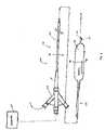
- FIG. 4is a schematic illustrating one embodiment of a vapor generator in accordance with the present invention.
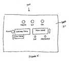
- FIG. 5illustrates one embodiment of a generator display or user interface
- FIG. 6is a perspective view of one embodiment of an energy delivery catheter in accordance with present invention.
- FIG. 7is a longitudinal cross-sectional view of yet another embodiment of a catheter in accordance with the present invention.
- FIG. 7Atransverse a cross-sectional view of the catheter of FIG. 7 taken along lines 7 A- 7 A;
- FIG. 7Bis a transverse cross-sectional view of catheter illustrated in FIG. 7 taken along lines 7 B- 7 B.
- FIG. 1illustrates a human respiratory system 10 .
- the respiratory system 10resides within the thorax 12 that occupies a space defined by the chest wall 14 and the diaphragm 16 .
- the human respiratory system 10includes left lung lobes 44 and 46 and right lung lobes 48 , 50 , and 52 .
- the respiratory system 10further includes trachea 18 ; left and right main stem bronchus 20 and 22 (primary, or first generation) and lobar bronchial branches 24 , 26 , 28 , 30 , and 32 (second generation). Segmental and sub-segmental branches further bifurcate off the lobar bronchial branches (third and fourth generation). Each bronchial branch and sub-branch communicates with a different portion of a lung lobe, either the entire lung lobe or a portion thereof.
- the term “air passageway” or “airway”means a bronchial branch of any generation, including the bronchioles and terminal bronchioles.
- FIG. 2is a perspective view of the airway anatomy emphasizing the upper right lung lobe 48 .
- FIG. 2shows sub-segmental bronchial branches (fourth generation) that provide air circulation (i.e. ventilation) to superior right lung lobe 48 .
- the bronchial segmentsbranch into six generations and the bronchioles branch into approximately another three to eight generations or orders.
- Each airway generationhas a smaller diameter than its predecessor, with the inside diameter of a generation varying depending on the particular bronchial branch, and further varying between individuals.
- a typical lobar bronchus providing air circulation to the upper right upper lobe 48has an internal diameter of approximately 1 cm.
- Typical segmental bronchihave internal diameter of approximately of about 4 to about 7 mm.
- a clear, thin, shiny coveringcovers the lungs.
- the inner, visceral layer of the pleurais attached to the lungs and the outer parietal layer is attached to the chest wall 14 . Both layers are held in place by a film of pleural fluid in a manner similar to two glass microscope slides that are wet and stuck together.
- the pleural membrane around each lungforms a continuous sac that encloses the lung and also forms a lining for the thoracic cavity 12 .
- the space between the pleural membranes forming the lining of the thoracic cavity 12 and the pleural membranes enclosing the lungsis referred to as the pleural cavity. If the air tight seal around the lungs created by the pleural members are breached (via a puncture, tear, or is otherwise damaged) air can enter the sac and cause the lungs to collapse.
- FIG. 3illustrates generally a procedure in accordance with the present invention.
- FIG. 3shows a bronchoscope 100 having a working channel into which an energy delivery catheter 200 is inserted. Bronchoscope 100 is inserted into a patient's lungs while the proximal portion of the energy delivery catheter 200 remaining outside of the patient. Energy delivery catheter 200 is adapted to operatively couple to an energy generator 300 as further discussed below.
- patientscan be intubated with a double-lumen endobronchial tube during the procedure, which allows for selective ventilation or deflation of the right and left lung.
- a double-lumen endobronchial tubeduring the procedure, which allows for selective ventilation or deflation of the right and left lung.
- the procedurecan be performed minimally invasively with energy catheter 200 introduced percutaneously through the chest wall and advanced to an appropriate location for with the aid of an introducer or guide sheath (with or without introduction into an airway).
- FIG. 4is a schematic diagram of one embodiment of the present invention wherein energy generator 300 is configured as a vapor generator.
- vapor generatoris configured to deliver a controlled dose of vapor to one or more target lung tissues.
- vapor generator 300is adapted to convert a biocompatible liquid 301 (e.g. saline, sterile water or other biocompatible liquid), into a wet or dry vapor, which is then delivered to one or more target tissues.
- a wet vaporrefers to a vapor that contains vaporous forms of the liquid as well as a non-negligible proportion of minute liquid droplets carried over with and held in suspension in the vapor.
- a dry vaporrefers to a vapor contained little or no liquid droplets.
- vapor generator 300is configured to have a liquid capacity between about 1000 to 2500 cc and configured to generate a vapor having a pressure between about 5-50 psig and temperatures between about 100-175° C.
- Vapor generator 300is preferably configured as a self-contained, medical-grade generator unit comprising at least a controller (not shown), a vaporizing unit 302 , a vapor inlet 304 , a vapor outlet 306 and a connective handle (not shown).
- the vaporizing unit 302comprises a fluid chamber for containing a fluid 302 , preferably a biocompatible, sterile fluid, in a liquid state.
- Vapor outlet 304is coupled to one or more pipes or tubes 310 , which in turn are in fluid communication with a vapor lumen of a hub assembly or other adapter, which in turn is adapted to operatively couple to the proximal end of energy delivery catheter 200 , several embodiments of which are further described below.
- Vapor flow from vapor generator 300 to a catheteris depicted as a vapor flow circuit 314 wherein flow of the vapor in circuit 314 is indicated by arrows 314 in FIG. 4 .
- Vaporizer unit 302is configured to heat and vaporize a liquid contained in a fluid chamber (not shown).
- Other componentscan be incorporated into the biocompatible liquid 301 or mixed into the vapor.
- these componentscan be used in order to control perioperative and/or post procedural pain, enhance tissue fibrosis, and/or control infection.
- Other constituents, for the purpose of regulating vapor temperatures and thus control extent and speed of tissue heating,can be incorporated; for example, in one implementation, carbon dioxide, helium, other noble gases can be mixed with the vapor to decrease vapor temperatures.
- Vaporizing unit 302further comprises a fluid inlet 304 that is provided to allow liquid 301 to be added to the fluid chamber as needed.
- Fluid chambercan be configured to accommodate or vaporize sufficient liquid as need to apply vapor to one or more target tissues.
- Liquid in vaporizing unit 302is heated and vaporized and the vapor flows into vapor outlet 304 .
- a number of hollow thermally conductive pipes 314are adapted to fluidly connect vapor outlet 304 and handle, which in turn is adapted to operatively couple to a variety of energy delivery catheters, which are further described below.
- Vapor flow through vapor flow circuit 314is unidirectional (in the direction of arrows 314 ). Accordingly one or more isolation valves 320 are incorporated in vapor flow circuit 314 . Isolation valves 320 , which are normally open during use of generator 300 , minimize vapor flow in a direction opposite that of the vapor flow circuit 314 .
- a priming line 330branching from main vapor flow circuit 314 , is provided to minimize or prevent undesirable liquid-state water formation during vapor flow through vapor flow circuit 314 .
- Pressure and temperature changes along vapor flow circuit 314can affect whether the vapor is sustainable in a vapor state or condensed back into a liquid.
- Priming line 330is provided to equalize temperatures and/or pressures along vapor flow circuit 314 in order to minimize or prevent undesirable liquid-state transition of the vapor during its progression through vapor flow circuit 314 .
- an initial “purge” or “priming” procedurecan be preformed prior to delivery of a therapeutic vapor dose in order to preheat flow, circuit 314 thus maintaining a constant temperature and pressure in the main vapor flow circuit 314 prior to delivery of a vapor to the target lung tissue.
- priming line 330terminates at evaporator 332 , which is adapted to either house undesirable liquid in a collection unit (not shown) located within generator 300 .
- collection unitis adapted to house the liquid until a user or clinician is able to empty said collection unit.
- evaporator 332is configured to evaporate and expel said undesirable liquid into the ambient air.
- Baffle plates (not shown) or other like meanscan be incorporated in evaporator 332 to facilitate maximal vapor-to-liquid transition. It should be understood that other suitable evaporator configurations could be included to facilitate vapor-to-liquid transition during a priming procedure of lines 314 .
- a number of sensorscan be incorporated into vapor generator 300 .
- a number of sensorscan be provided in the liquid chamber, or along any point in vapor flow circuit 314 .
- Water level sensorsadapted to monitor the water level in the liquid chamber, can be included. These water level sensors are configured as upper and lower security sensors to sense or indicate when a liquid level in the fluid chamber is below or above a set fluid level. In example, if a water level in the fluid chamber falls below the level of a lower water control sensor, the controller can be configured to interrupt the operation of the vapor generator 300 .
- pressure sensorscan be included in vaporizing unit 302 , or at various points along the vapor flow circuit 314 , to measure the liquid or vapor pressures at various discrete locations and/or to measure vapor pressures within a defined segment along circuit 314 .
- One or more control valves 320can also be installed at various points in the vapor flow circuit 314 to control vapor flow for instance to control or increase the vapor flow or vapor flow rates in vapor flow circuit 314 .
- a safety valve 322can be incorporated into the liquid chamber of vaporizing unit 302 and coupled to a vapor overflow line 340 if the need for removing or venting vaporizing unit 302 arises during generator 300 operation.
- FIG. 5illustrates one embodiment of a user interface 360 of vapor generator 300 .
- the user interface 360comprises various visual readouts intended to provide clinical users information about various treatment parameters of interest, such as pressure, temperature and/or duration of vapor delivery.
- Vapor generator 300can also be adapted to incorporate one or more auditory alerts, in addition or in lieu of, visual indicators provided on user interface 360 . These one or more auditory alerts are designed to provide an alert to a clinical user, such as when vapor delivery is complete, when liquid chamber must be refilled or the like.
- a keyboardcan be incorporated with other components, while not shown, including any of the following: a keyboard; a real-time imaging system display (such as a CT, fluoroscopy, ultrasound); memory system; and/or one or more recording systems.
- a real-time imaging system displaysuch as a CT, fluoroscopy, ultrasound
- memory systemcan be incorporated with other components, while not shown, including any of the following: a keyboard; a real-time imaging system display (such as a CT, fluoroscopy, ultrasound); memory system; and/or one or more recording systems.
- FIG. 6illustrates yet another aspect of the invention, in particular a vapor catheter 200 embodying various features of the present invention.
- catheter 200is adapted to operatively connect to a control handle of vapor generator 300 via hub assembly 202 .
- Catheter 200includes elongate shaft 204 defined by proximal section 206 and distal section 208 .
- Elongated shaft 204is formed with at least one lumen (such as a vapor, inflation, sensing, imaging, guide wire, vacuum lumen) extending from proximal section 206 to distal section 208 of shaft 204 .
- catheter 200comprises strain relief member 201 .
- Elongated shaft 204further comprises at least one occlusive member 210 disposed at distal section 208 and distal tip 210 having at least one distal port 212 .
- the at least one distal port 212is configured as a vapor outlet port.
- vapor outlet portmay also be used as an aspiration port while catheter is coupled to a vacuum source (not shown) in order to aspirate mucus, fluids, and other debris from an airway through which catheter 200 is advanced prior to vapor delivery.
- catheter 200can be configured to include a separate vacuum lumen and aspiration ports as needed.
- Distal tip 210can be adapted into a variety of shapes depending on the specific clinical need and application. For example, distal tip 210 can be adapted to be atraumatic in order to minimize airway damage during delivery.
- catheter 200is low profile to facilitate placement of catheter distal tip 210 as close as practicable to proximally and peripherally located target lung tissue, i.e. in order to facilitate the catheter's advancement into smaller and deeper airways.
- the low profile feature of catheter 200also ensures that catheter can be delivered to the lungs and airways through a working channel of a bronchoscope, including for example, through the working channels of ultra-thin bronchoscopes.
- catheter 200is slidably advanced and retracted from a bronchoscope working channel.
- the overall length and diameter of catheter 200can be varied and adapted according to: the specific clinical application; size of the airway to be navigated; and/or the location of the one or more target tissues.
- Occlusive member or members 210are similarly configured to provide the smallest possible size when deflated to facilitate ready retraction of catheter 200 back into the working channel of a bronchoscope following completion of a treatment procedure involving delivery of one or more vapor doses to one or more target tissues.
- the one or more occlusive members 210are provided to obstruct of proximal vapor flow and/or seat catheter 200 in the patient's airway during vapor delivery without slipping.
- Obstruction of an airway by occlusive member 210prevents retrograde flow of vapor to tissues located outside of the desired target tissues. Because of the physiological characteristics of the airways, in particular the fact that the airways ventilate and communicate specific lung parenchyma or tissues, vapor delivered or dispersed at a particular airway location (e.g. at the bronchial, sub segmental, main bronchi) determines whether there is a focal or regional heating of tissue. In addition to location of the catheter distal tip, other considerations that impact whether there is focal or regional tissue heating patterns (i.e. volume of tissue heated or size of thermal lesion) created include: time or duration of vapor delivery; the vapor flow rate; and vapor content (dry vs. wet; vapor alone vs. vapor cocktail). Preferably, the one or more occlusive members 210 are compliant to ensure: adequate seating; airway obstruction; and/or complete collapse following deflation.
- Catheter 200can be fabricated from a variety of suitable materials and formed by any process such as extrusion, blow molding, or other methods well know in the art. In general, catheter 200 and its various components are fabricated from materials that are relatively flexible (for advancement into tortuous airways) yet having good pushability characteristics and durable enough to withstanding the high temperatures and pressures of the vapor delivered using catheter 200 .
- Catheter 200 and elongated shaft 204can be a tubular braided polyimide, silicone, or reinforced silicone. These materials are relatively flexible, yet have good pushability characteristics, while able to withstand the high temperature and pressures of vapor flow. Suitable materials should be adapted to withstand vapor pressures of up to 80 psig, at temperatures up to 170° C. Specific suitable materials include, for example, various braided polyimide tubing available, for example, from IW High Performance Conductors, Inc.
- the one or more occlusive members 210are preferably fabricated from similar materials having pressure and temperature tolerant attributes as elongated shaft 204 , but preferably which is also compliant, such as silicone available from Dow Corning Q74720.
- catheter 200 and elongated shaft 204can further be adapted to include varying flexibility and stiffness characteristics along the length of shaft 204 based on the clinical requirements and desired advantages.
- various sensing membersincluding for example pressure, temperature and flow sensors known in the art can be incorporated into catheter 200 .
- catheter 200can be adapted to include a sensing lumen for advancement or connection with various sensory devices such as pressure, temperature and flow sensors.
- FIG. 7is a longitudinal cross sectional view of the elongate shaft 404 while FIGS. 7A and 7B show transverse cross sectional views of the elongate shaft 404 taken along the lines 7 A- 7 A and lines 7 B- 7 B respectively.
- catheter 400comprises an elongated catheter shaft 404 having an outer tubular member 406 and an inner tubular member 408 disposed within outer tubular member 406 .
- Inner tubular member 408defines a vapor lumen 410 adapted to receive a vapor and which is in fluid communication with a vapor flow circuit 314 of generator 300 .
- the coaxial relationship between outer tubular member 406 and inner tubular member 408defines annular inflation lumen 412 .
- Vapor lumen 410terminates at vapor port 424 .
- Inflation balloon 414is disposed on a distal section of elongated catheter shaft 404 and having proximal 416 and distal 418 balloon ends sealingly secured to outer tubular member 406 .
- One or more inflation ports 420are disposed on outer tubular member 406 between the proximal 416 and distal 418 ends of inflation balloon 414 so that the interior of inflation balloon 414 is in fluid communication with inflation lumen 412 . (See FIG. 7B .)
- structural members 422are disposed between inner tubular member 408 and outer tubular member 406 at distal vapor port 424 to seal inflation lumen 412 and provide structural integrity at the catheter tip.
- Structural members 422are preferably made of stainless steel, nickel titanium alloys, gold, gold plated materials or other radiopaque materials, to provide catheter tip visibility under fluoroscopy and/or provide sufficient echogenicity so that the catheter tip is detectable using ultrasonography.
- Hub assembly 426 (or other adaptor) at the proximal end of catheter 400is configured to direct an inflation fluid (such as a liquid or air) into inflation lumen 412 as well as provide access to vapor lumen 410 .
- an inflation fluidsuch as a liquid or air
- FIG. 7Billustrates inflation balloon 414 in an inflated or expanded configuration.
- Inflation balloon 414inflates to a cylindrical cross section equal to that of a target airway in order to obstruct the airway and prevent proximal or retrograde vapor flow.
- This inflated configurationis achieved at an inflation pressure within the working pressure range of balloon 414 .
- Inflation balloon 414has a working length, which is sufficiently long to provide adequate seating in a target airway without slippage during or prior to vapor delivery.
- Suitable dimensions for the vapor catheter 400 in accordance with the present inventioninclude an outer tubular member 406 which has an outer diameter of about 0.05 to about 0.16 inches, usually about 0.065 inches and an inner diameter of about 0.04 to about 0.15 inches, usually about 0.059 inches.
- the wall thickness of outer tubular member 406 and inner tubular member 408can vary from about 0.001 to about 0.005 inches, typically about 0.003 inches.
- the inner tubular member 408typically has an outer diameter of about 0.04 to about 0.15 inches, usually about 0.054 inches and an inner diameter of about 0.03 to about 0.14 inches, usually about 0.048 inches.
- the overall working length of catheter 400may range from about 50 to about 150 cm, typically about 110 to about 120 cm.
- inflation balloon 414has a total length about 5 to about 20 mm; a working length of about 1 to about 18 mm, preferably about 4 to about 8 mm.
- Inflation balloon 414has an inflated working outer diameter of about 4 to about 20 mm, preferably about 4 to about 8 mm within a working pressure range of inflation balloon 414 .
- outer tubular member 406 and inner tubular member 408is braided polyimide tubular member from IWG High Performance Conductors.
- the braided polyimide tubular membercomprises braided stainless steel, with the braid comprising rectangular or round stainless steel wires.
- the braided stainless steelhas about 90 picks per inch.
- the individual stainless steel strandsmay be coated with heat resistant polyimide and then braided or otherwise formed into a tubular member or the stainless steel wires or strands may be braided or otherwise formed into a tubular product and the braided surfaces of the tubular product may be coated with a heat resistant polyimide.
- the catheters and generators of the present inventioncan be used to heat one or more target lung tissue to treat a variety of lung diseases and conditions, including but not limited to: lung tumors, solitary pulmonary nodules, lung abscesses, tuberculosis, as well as a variety of other diseases and disorders.
- a procedure for inducing lung volume reductioninvolves advancing catheter 400 into a segmental or sub-segmental airway and delivering a controlled vapor dose.
- the vaporcarries most of the energy and heat required to convert liquid in vapor generator from a liquid into a vapor.
- Vapor heating of target lung tissueis intended to cause tissue injury, shrinkage and/or ablation, in order to cause volumetric reduction of one or more target lung tissues. Lung volume reduction is immediate and/or occurs over several weeks or months.
- catheter 400is navigated into one or more airways, preferably as into the segmental or sub-segmental airways and the vapor delivered into as many airway as need during a single procedure to effect the therapeutically optimal extent of lung volume reduction.
- a vapor generatorconfigured to create a vapor having a vapor pressure between about 5-50 psig, at a temperature between about 100°-170° degrees C. within vapor generator 300 is employed.
- the vapor catheteris delivered into the sub-segmental airways that communicate with either the left and right upper lobes, and vapor delivered for a period of 1-20 seconds in each of these airways, to effect volumetric reduction of the left and right upper lobes.
- energy deliver to a target lung tissueis achieved without attendant plural heating sufficient to cause damage to the pleura or a pneumothoraces.
- vapor treatment procedurescan be employed before, during and after a vapor treatment procedure.
- Real time fluoroscopycan be used to confirm depth of catheter 400 inside a patient's lung as well as confirm position of catheter in a desired airway.
- real-time CT guided electromagnetic navigational systemssuch as the SuperDimension®/Bronchus system can be employed to accurately guide catheters of the present invention to the desired tissues targets, especially to get the catheters close to target tissues that are peripherally located.
- the present inventioncan be adapted to work through a working channel of a locatable guide or guide catheter of the SuperDimension CT navigational system.
- a medical kit for performing volumetric vapor heating of one or more target lung tissueswhich comprises a packaged, sterile liquid or liquid composition and a high temperature vapor delivery catheter.
- Other embodiments of said medical kitscan comprise instructions of use, syringes, and the like.
Landscapes
- Health & Medical Sciences (AREA)
- Life Sciences & Earth Sciences (AREA)
- Heart & Thoracic Surgery (AREA)
- Engineering & Computer Science (AREA)
- Public Health (AREA)
- Biomedical Technology (AREA)
- Animal Behavior & Ethology (AREA)
- General Health & Medical Sciences (AREA)
- Veterinary Medicine (AREA)
- Hematology (AREA)
- Anesthesiology (AREA)
- Surgery (AREA)
- Biophysics (AREA)
- Child & Adolescent Psychology (AREA)
- Pulmonology (AREA)
- Physics & Mathematics (AREA)
- Plasma & Fusion (AREA)
- Nuclear Medicine, Radiotherapy & Molecular Imaging (AREA)
- Otolaryngology (AREA)
- Vascular Medicine (AREA)
- Medical Informatics (AREA)
- Molecular Biology (AREA)
- Surgical Instruments (AREA)
Abstract
Description
- This application is related to application Ser. No. ______ concurrently filed Nov. 13, 2006, entitled High Pressure and High Temperature Vapor Catheters and Systems, which is incorporated by reference herein in its entirety.
- This invention relates to medical devices, systems and methods, and in particular to intrabronchial catheters, systems and methods for delivering a high pressure, high temperature vapor to one or more tissue targets in a patient's lungs.
- Heating therapies are increasingly used in various medical disciplines including cardiology, dermatology, orthopedics, oncology as well as a number of other medical specialties. In general, the manifold clinical effects of superphysiological tissue temperatures results from underlying molecular and cellular responses, including expression of heat-shock proteins, cell death, protein denaturation, tissue coagulation and ablation. Associated with these heat-induced cellular alternations and responses are dramatic changes in tissue structure, function and properties that can be exploited for a desired therapeutic outcome such as tissue injury, shrinkage, modification, destruction and/or removal.
- Heating techniques in the lung pose several technical challenges because lung tissue is more aerated than most tissues and also due to its vascularization. Accordingly, these new heating methods, devices and systems for rapid, controllable, effective and efficient heating of lung tissue are needed. The present invention is directed at meeting these as well as other needs.
- The present invention relates to novel methods for treating an intraluminal location by volumetricly heating one or more target tissues and particularly tissue in a patient's lungs. Preferably, the one or more target tissues are heated to superphysiological temperatures (temperatures above at least 45° C.) by dispersing a high temperature vapor into an airway (e.g. intrabronchial location) that ventilates the one or more target tissues. Because of the physiological characteristics of the airways, the vapor can be delivered focally or regionally dependant largely on where in the airways the vapor is dispersed. The target tissue is heated without causing pneumothorax.
- In a first aspect of the invention, a method of treating a patient's lungs comprises providing an elongated device such as a catheter which has an inner lumen formed of heat resistant materials and configured to deliver heated vapor to a port in a distal portion of the catheter; advancing the catheter within the patient to a desired location therein, such as a lung; and delivering heated vapor through the inner lumen. Preferably, catheter has an inflatable member on a distal portion of the catheter and the inflatable member is inflated before heated vapor is delivered through the inner lumen to prevent proximal flow of the heated vapor.
- All publications and patent applications mentioned in this specification are herein incorporated by reference to the same extent as if each individual publication or patent application was specifically and individually indicated to be incorporated by reference.
- The novel features of the invention are set forth with particularity in the appended claims. A better understanding of the features and advantages of the present invention will be obtained by reference to the following detailed description that sets forth illustrative embodiments, in which the principles of the invention are utilized, and the accompanying drawings of which:
FIG. 1 illustrates a human respiratory system;FIG. 2 illustrates the airway in the respiratory system;FIG. 3 illustrates one method of treating a volume of lung tissue in accordance with the present invention;FIG. 4 is a schematic illustrating one embodiment of a vapor generator in accordance with the present invention;FIG. 5 illustrates one embodiment of a generator display or user interface;FIG. 6 is a perspective view of one embodiment of an energy delivery catheter in accordance with present invention;FIG. 7 is a longitudinal cross-sectional view of yet another embodiment of a catheter in accordance with the present invention;FIG. 7A transverse a cross-sectional view of the catheter ofFIG. 7 taken along lines7A-7A; andFIG. 7B is a transverse cross-sectional view of catheter illustrated inFIG. 7 taken along lines7B-7B.FIG. 1 illustrates a humanrespiratory system 10. Therespiratory system 10 resides within thethorax 12 that occupies a space defined by thechest wall 14 and thediaphragm 16. The humanrespiratory system 10 includesleft lung lobes 44 and46 andright lung lobes - The
respiratory system 10 further includestrachea 18; left and rightmain stem bronchus 20 and22 (primary, or first generation) and lobarbronchial branches FIG. 2 is a perspective view of the airway anatomy emphasizing the upperright lung lobe 48. In addition to the bronchial branches illustrated inFIG. 1 ,FIG. 2 shows sub-segmental bronchial branches (fourth generation) that provide air circulation (i.e. ventilation) to superiorright lung lobe 48. The bronchial segments branch into six generations and the bronchioles branch into approximately another three to eight generations or orders. Each airway generation has a smaller diameter than its predecessor, with the inside diameter of a generation varying depending on the particular bronchial branch, and further varying between individuals. A typical lobar bronchus providing air circulation to the upper rightupper lobe 48 has an internal diameter of approximately 1 cm. Typical segmental bronchi have internal diameter of approximately of about 4 to about 7 mm.- The airways of the lungs branch much like the roots of a tree and anatomically constitute an extensive network of air flow conduits that reach all lung areas and tissues. The airways have extensive branching that distally communicates with the parenchyma alveoli where gas exchange occurs. Because of these physiological characteristics of the airways, a medium, such as a vapor, delivered through an airway can be delivered focally or more regionally depending largely on the airway location at which the medium is delivered or dispersed.
- While not illustrated, a clear, thin, shiny covering, known as the serous coat or pleura, covers the lungs. The inner, visceral layer of the pleura is attached to the lungs and the outer parietal layer is attached to the
chest wall 14. Both layers are held in place by a film of pleural fluid in a manner similar to two glass microscope slides that are wet and stuck together. Essentially, the pleural membrane around each lung forms a continuous sac that encloses the lung and also forms a lining for thethoracic cavity 12. The space between the pleural membranes forming the lining of thethoracic cavity 12 and the pleural membranes enclosing the lungs is referred to as the pleural cavity. If the air tight seal around the lungs created by the pleural members are breached (via a puncture, tear, or is otherwise damaged) air can enter the sac and cause the lungs to collapse. FIG. 3 illustrates generally a procedure in accordance with the present invention.FIG. 3 shows abronchoscope 100 having a working channel into which anenergy delivery catheter 200 is inserted.Bronchoscope 100 is inserted into a patient's lungs while the proximal portion of theenergy delivery catheter 200 remaining outside of the patient.Energy delivery catheter 200 is adapted to operatively couple to anenergy generator 300 as further discussed below.- Though not illustrated, patients can be intubated with a double-lumen endobronchial tube during the procedure, which allows for selective ventilation or deflation of the right and left lung. Depending on the location or locations of the target lung tissues to be treated, it may be preferable to stop ventilation of the target lung tissue. Also, while not illustrated, in an alternative embodiment, the procedure can be performed minimally invasively with
energy catheter 200 introduced percutaneously through the chest wall and advanced to an appropriate location for with the aid of an introducer or guide sheath (with or without introduction into an airway). FIG. 4 is a schematic diagram of one embodiment of the present invention whereinenergy generator 300 is configured as a vapor generator. Preferably, vapor generator is configured to deliver a controlled dose of vapor to one or more target lung tissues. Generally,vapor generator 300 is adapted to convert a biocompatible liquid301 (e.g. saline, sterile water or other biocompatible liquid), into a wet or dry vapor, which is then delivered to one or more target tissues. A wet vapor refers to a vapor that contains vaporous forms of the liquid as well as a non-negligible proportion of minute liquid droplets carried over with and held in suspension in the vapor. A dry vapor refers to a vapor contained little or no liquid droplets. In general,vapor generator 300 is configured to have a liquid capacity between about 1000 to 2500 cc and configured to generate a vapor having a pressure between about 5-50 psig and temperatures between about 100-175° C.Vapor generator 300 is preferably configured as a self-contained, medical-grade generator unit comprising at least a controller (not shown), a vaporizing unit302, avapor inlet 304, a vapor outlet306 and a connective handle (not shown). The vaporizing unit302 comprises a fluid chamber for containing a fluid302, preferably a biocompatible, sterile fluid, in a liquid state.Vapor outlet 304 is coupled to one or more pipes or tubes310, which in turn are in fluid communication with a vapor lumen of a hub assembly or other adapter, which in turn is adapted to operatively couple to the proximal end ofenergy delivery catheter 200, several embodiments of which are further described below. Vapor flow fromvapor generator 300 to a catheter (and specifically a vapor lumen of said catheter) is depicted as avapor flow circuit 314 wherein flow of the vapor incircuit 314 is indicated byarrows 314 inFIG. 4 .- Vaporizer unit302 is configured to heat and vaporize a liquid contained in a fluid chamber (not shown). Other components can be incorporated into the
biocompatible liquid 301 or mixed into the vapor. For example, these components can be used in order to control perioperative and/or post procedural pain, enhance tissue fibrosis, and/or control infection. Other constituents, for the purpose of regulating vapor temperatures and thus control extent and speed of tissue heating, can be incorporated; for example, in one implementation, carbon dioxide, helium, other noble gases can be mixed with the vapor to decrease vapor temperatures. - Vaporizing unit302 further comprises a
fluid inlet 304 that is provided to allow liquid301 to be added to the fluid chamber as needed. Fluid chamber can be configured to accommodate or vaporize sufficient liquid as need to apply vapor to one or more target tissues. Liquid in vaporizing unit302 is heated and vaporized and the vapor flows intovapor outlet 304. A number of hollow thermallyconductive pipes 314 are adapted to fluidly connectvapor outlet 304 and handle, which in turn is adapted to operatively couple to a variety of energy delivery catheters, which are further described below. Preferably, there is little or no vapor-to-liquid transition during movement of the vapor throughvapor flow circuit 314. Vapor flow throughvapor flow circuit 314 is unidirectional (in the direction of arrows314). Accordingly one or more isolation valves320 are incorporated invapor flow circuit 314. Isolation valves320, which are normally open during use ofgenerator 300, minimize vapor flow in a direction opposite that of thevapor flow circuit 314. - A
priming line 330, branching from mainvapor flow circuit 314, is provided to minimize or prevent undesirable liquid-state water formation during vapor flow throughvapor flow circuit 314. Pressure and temperature changes alongvapor flow circuit 314 can affect whether the vapor is sustainable in a vapor state or condensed back into a liquid. Primingline 330 is provided to equalize temperatures and/or pressures alongvapor flow circuit 314 in order to minimize or prevent undesirable liquid-state transition of the vapor during its progression throughvapor flow circuit 314. In one embodiment, an initial “purge” or “priming” procedure can be preformed prior to delivery of a therapeutic vapor dose in order to preheat flow,circuit 314 thus maintaining a constant temperature and pressure in the mainvapor flow circuit 314 prior to delivery of a vapor to the target lung tissue. - As shown in
FIG. 4 , primingline 330 terminates at evaporator332, which is adapted to either house undesirable liquid in a collection unit (not shown) located withingenerator 300. In one embodiment, collection unit is adapted to house the liquid until a user or clinician is able to empty said collection unit. Alternatively, evaporator332 is configured to evaporate and expel said undesirable liquid into the ambient air. Baffle plates (not shown) or other like means can be incorporated in evaporator332 to facilitate maximal vapor-to-liquid transition. It should be understood that other suitable evaporator configurations could be included to facilitate vapor-to-liquid transition during a priming procedure oflines 314. - A number of sensors, operatively connected to a controller, can be incorporated into
vapor generator 300. For example, in the liquid chamber, or along any point invapor flow circuit 314, a number of sensors can be provided. Water level sensors, adapted to monitor the water level in the liquid chamber, can be included. These water level sensors are configured as upper and lower security sensors to sense or indicate when a liquid level in the fluid chamber is below or above a set fluid level. In example, if a water level in the fluid chamber falls below the level of a lower water control sensor, the controller can be configured to interrupt the operation of thevapor generator 300. - In yet another embodiment, pressure sensors, or manometers, can be included in vaporizing unit302, or at various points along the
vapor flow circuit 314, to measure the liquid or vapor pressures at various discrete locations and/or to measure vapor pressures within a defined segment alongcircuit 314. One or more control valves320 can also be installed at various points in thevapor flow circuit 314 to control vapor flow for instance to control or increase the vapor flow or vapor flow rates invapor flow circuit 314. In yet another embodiment, asafety valve 322 can be incorporated into the liquid chamber of vaporizing unit302 and coupled to a vapor overflow line340 if the need for removing or venting vaporizing unit302 arises duringgenerator 300 operation. FIG. 5 illustrates one embodiment of a user interface360 ofvapor generator 300. As illustrated, the user interface360 comprises various visual readouts intended to provide clinical users information about various treatment parameters of interest, such as pressure, temperature and/or duration of vapor delivery.Vapor generator 300 can also be adapted to incorporate one or more auditory alerts, in addition or in lieu of, visual indicators provided on user interface360. These one or more auditory alerts are designed to provide an alert to a clinical user, such as when vapor delivery is complete, when liquid chamber must be refilled or the like. As will be recognized by those in the art, other components, while not shown, can be incorporated including any of the following: a keyboard; a real-time imaging system display (such as a CT, fluoroscopy, ultrasound); memory system; and/or one or more recording systems.FIG. 6 illustrates yet another aspect of the invention, in particular avapor catheter 200 embodying various features of the present invention. Generally,catheter 200 is adapted to operatively connect to a control handle ofvapor generator 300 viahub assembly 202.Catheter 200 includeselongate shaft 204 defined byproximal section 206 and distal section208.Elongated shaft 204 is formed with at least one lumen (such as a vapor, inflation, sensing, imaging, guide wire, vacuum lumen) extending fromproximal section 206 to distal section208 ofshaft 204. Starting atproximal section 206,catheter 200 comprisesstrain relief member 201.Elongated shaft 204 further comprises at least oneocclusive member 210 disposed at distal section208 anddistal tip 210 having at least one distal port212. In one embodiment, the at least one distal port212 is configured as a vapor outlet port. In yet another embodiment, vapor outlet port may also be used as an aspiration port while catheter is coupled to a vacuum source (not shown) in order to aspirate mucus, fluids, and other debris from an airway through whichcatheter 200 is advanced prior to vapor delivery. Alternatively,catheter 200 can be configured to include a separate vacuum lumen and aspiration ports as needed.Distal tip 210 can be adapted into a variety of shapes depending on the specific clinical need and application. For example,distal tip 210 can be adapted to be atraumatic in order to minimize airway damage during delivery.- The dimensions of the catheter are determined largely by the size airway lumen through which the catheter must pass in order to deliver the catheter to an airway location appropriate for treatment of the one or more target tissues. An airway location appropriate for treatment of a target lung tissue depends on the volume of the target tissue and the proximity of catheter tip to the target tissue. Generally,
catheter 200 is low profile to facilitate placement of catheterdistal tip 210 as close as practicable to proximally and peripherally located target lung tissue, i.e. in order to facilitate the catheter's advancement into smaller and deeper airways. In addition, the low profile feature ofcatheter 200 also ensures that catheter can be delivered to the lungs and airways through a working channel of a bronchoscope, including for example, through the working channels of ultra-thin bronchoscopes. Preferably,catheter 200 is slidably advanced and retracted from a bronchoscope working channel. The overall length and diameter ofcatheter 200 can be varied and adapted according to: the specific clinical application; size of the airway to be navigated; and/or the location of the one or more target tissues. - Occlusive member or
members 210 are similarly configured to provide the smallest possible size when deflated to facilitate ready retraction ofcatheter 200 back into the working channel of a bronchoscope following completion of a treatment procedure involving delivery of one or more vapor doses to one or more target tissues. The one or moreocclusive members 210 are provided to obstruct of proximal vapor flow and/orseat catheter 200 in the patient's airway during vapor delivery without slipping. - Obstruction of an airway by
occlusive member 210 prevents retrograde flow of vapor to tissues located outside of the desired target tissues. Because of the physiological characteristics of the airways, in particular the fact that the airways ventilate and communicate specific lung parenchyma or tissues, vapor delivered or dispersed at a particular airway location (e.g. at the bronchial, sub segmental, main bronchi) determines whether there is a focal or regional heating of tissue. In addition to location of the catheter distal tip, other considerations that impact whether there is focal or regional tissue heating patterns (i.e. volume of tissue heated or size of thermal lesion) created include: time or duration of vapor delivery; the vapor flow rate; and vapor content (dry vs. wet; vapor alone vs. vapor cocktail). Preferably, the one or moreocclusive members 210 are compliant to ensure: adequate seating; airway obstruction; and/or complete collapse following deflation. Catheter 200 can be fabricated from a variety of suitable materials and formed by any process such as extrusion, blow molding, or other methods well know in the art. In general,catheter 200 and its various components are fabricated from materials that are relatively flexible (for advancement into tortuous airways) yet having good pushability characteristics and durable enough to withstanding the high temperatures and pressures of the vapor delivered usingcatheter 200.Catheter 200 andelongated shaft 204 can be a tubular braided polyimide, silicone, or reinforced silicone. These materials are relatively flexible, yet have good pushability characteristics, while able to withstand the high temperature and pressures of vapor flow. Suitable materials should be adapted to withstand vapor pressures of up to 80 psig, at temperatures up to 170° C. Specific suitable materials include, for example, various braided polyimide tubing available, for example, from IW High Performance Conductors, Inc. (See www.iwghpc.com/MedicalProducts/Tubing.html.) Similarly, the one or moreocclusive members 210 are preferably fabricated from similar materials having pressure and temperature tolerant attributes aselongated shaft 204, but preferably which is also compliant, such as silicone available from Dow Corning Q74720. As an added feature,catheter 200 andelongated shaft 204 can further be adapted to include varying flexibility and stiffness characteristics along the length ofshaft 204 based on the clinical requirements and desired advantages. While not shown, various sensing members, including for example pressure, temperature and flow sensors known in the art can be incorporated intocatheter 200. For example,catheter 200 can be adapted to include a sensing lumen for advancement or connection with various sensory devices such as pressure, temperature and flow sensors.- Turing now to
FIG. 7 , illustrated is a preferred embodiment of avapor catheter 400.FIG. 7 is a longitudinal cross sectional view of theelongate shaft 404 whileFIGS. 7A and 7B show transverse cross sectional views of theelongate shaft 404 taken along the lines7A-7A and lines7B-7B respectively. - In this preferred embodiment,
catheter 400 comprises anelongated catheter shaft 404 having an outertubular member 406 and an innertubular member 408 disposed within outertubular member 406. Innertubular member 408 defines avapor lumen 410 adapted to receive a vapor and which is in fluid communication with avapor flow circuit 314 ofgenerator 300. The coaxial relationship between outertubular member 406 and innertubular member 408 definesannular inflation lumen 412.Vapor lumen 410 terminates atvapor port 424. Inflation balloon 414 is disposed on a distal section ofelongated catheter shaft 404 and having proximal416 and distal418 balloon ends sealingly secured to outertubular member 406. One or more inflation ports420 are disposed on outertubular member 406 between the proximal416 and distal418 ends ofinflation balloon 414 so that the interior ofinflation balloon 414 is in fluid communication withinflation lumen 412. (SeeFIG. 7B .)- As shown in
FIG. 7 ,structural members 422 are disposed between innertubular member 408 and outertubular member 406 atdistal vapor port 424 to sealinflation lumen 412 and provide structural integrity at the catheter tip.Structural members 422 are preferably made of stainless steel, nickel titanium alloys, gold, gold plated materials or other radiopaque materials, to provide catheter tip visibility under fluoroscopy and/or provide sufficient echogenicity so that the catheter tip is detectable using ultrasonography. Hub assembly426 (or other adaptor) at the proximal end ofcatheter 400 is configured to direct an inflation fluid (such as a liquid or air) intoinflation lumen 412 as well as provide access tovapor lumen 410. FIG. 7B illustratesinflation balloon 414 in an inflated or expanded configuration.Inflation balloon 414 inflates to a cylindrical cross section equal to that of a target airway in order to obstruct the airway and prevent proximal or retrograde vapor flow. This inflated configuration is achieved at an inflation pressure within the working pressure range ofballoon 414.Inflation balloon 414 has a working length, which is sufficiently long to provide adequate seating in a target airway without slippage during or prior to vapor delivery.- Suitable dimensions for the
vapor catheter 400 in accordance with the present invention include an outertubular member 406 which has an outer diameter of about 0.05 to about 0.16 inches, usually about 0.065 inches and an inner diameter of about 0.04 to about 0.15 inches, usually about 0.059 inches. The wall thickness of outertubular member 406 and innertubular member 408 can vary from about 0.001 to about 0.005 inches, typically about 0.003 inches. The innertubular member 408 typically has an outer diameter of about 0.04 to about 0.15 inches, usually about 0.054 inches and an inner diameter of about 0.03 to about 0.14 inches, usually about 0.048 inches. - The overall working length of
catheter 400 may range from about 50 to about 150 cm, typically about 110 to about 120 cm. Preferably,inflation balloon 414 has a total length about 5 to about 20 mm; a working length of about 1 to about 18 mm, preferably about 4 to about 8 mm.Inflation balloon 414 has an inflated working outer diameter of about 4 to about 20 mm, preferably about 4 to about 8 mm within a working pressure range ofinflation balloon 414. In preferred embodiment, outertubular member 406 and innertubular member 408 is braided polyimide tubular member from IWG High Performance Conductors. Specifically, the braided polyimide tubular member comprises braided stainless steel, with the braid comprising rectangular or round stainless steel wires. Preferably, the braided stainless steel has about 90 picks per inch. The individual stainless steel strands may be coated with heat resistant polyimide and then braided or otherwise formed into a tubular member or the stainless steel wires or strands may be braided or otherwise formed into a tubular product and the braided surfaces of the tubular product may be coated with a heat resistant polyimide. - As will be appreciated by those skilled in the art, the catheters and generators of the present invention can be used to heat one or more target lung tissue to treat a variety of lung diseases and conditions, including but not limited to: lung tumors, solitary pulmonary nodules, lung abscesses, tuberculosis, as well as a variety of other diseases and disorders. In one embodiment, a procedure for inducing lung volume reduction (as a treatment for emphysema) involves advancing
catheter 400 into a segmental or sub-segmental airway and delivering a controlled vapor dose. As will be appreciated by those skilled in the art, the vapor carries most of the energy and heat required to convert liquid in vapor generator from a liquid into a vapor. Upon dispersion of the vapor into the airways, the vapor penetrates into the interstitial channels between the cells, and distributes thermal area over a relatively large volume of tissue, permitting tissue heating to be accomplished quickly, usually with a few seconds or minutes. Vapor heating of target lung tissue is intended to cause tissue injury, shrinkage and/or ablation, in order to cause volumetric reduction of one or more target lung tissues. Lung volume reduction is immediate and/or occurs over several weeks or months. - Depending on the extent of the volumetric reduction (complete or partial reduction of a lobe) desired,
catheter 400 is navigated into one or more airways, preferably as into the segmental or sub-segmental airways and the vapor delivered into as many airway as need during a single procedure to effect the therapeutically optimal extent of lung volume reduction. In a preferred embodiment, a vapor generator configured to create a vapor having a vapor pressure between about 5-50 psig, at a temperature between about 100°-170° degrees C. withinvapor generator 300 is employed. The vapor catheter is delivered into the sub-segmental airways that communicate with either the left and right upper lobes, and vapor delivered for a period of 1-20 seconds in each of these airways, to effect volumetric reduction of the left and right upper lobes. Preferably, energy deliver to a target lung tissue is achieved without attendant plural heating sufficient to cause damage to the pleura or a pneumothoraces. - As will be appreciated by one skilled in the art, various imaging techniques (in addition to or in lieu of conventional bronchoscopic imaging) can be employed before, during and after a vapor treatment procedure. Real time fluoroscopy can be used to confirm depth of
catheter 400 inside a patient's lung as well as confirm position of catheter in a desired airway. In yet another embodiment, real-time CT guided electromagnetic navigational systems, such as the SuperDimension®/Bronchus system can be employed to accurately guide catheters of the present invention to the desired tissues targets, especially to get the catheters close to target tissues that are peripherally located. In one embodiment of the invention, the present invention can be adapted to work through a working channel of a locatable guide or guide catheter of the SuperDimension CT navigational system. - A medical kit for performing volumetric vapor heating of one or more target lung tissues which comprises a packaged, sterile liquid or liquid composition and a high temperature vapor delivery catheter. Other embodiments of said medical kits can comprise instructions of use, syringes, and the like.
- The invention has been discussed in terms of certain embodiments. One of skill in the art, however, will recognize that various modifications may be made without departing from the scope of the invention. For example, numerous variations, changes, and substitutions will now occur to those skilled in the art without departing from the invention. Moreover, while certain features may be shown or discussed in relation to a particular embodiment, such individual features may be used on the various other embodiments of the invention. In addition, while not provided, other energy modalities can be employed for volumetric heating of target lung tissue and its understood that in conjunction with or instead of vapor, such as modalities such as RF, laser, microwave, cryogenic fluid, a resistive heating source, ultrasound and other energy delivery mechanisms can be employed for heating a target lung volume.
Claims (17)
Priority Applications (6)
| Application Number | Priority Date | Filing Date | Title |
|---|---|---|---|
| US11/598,362US8585645B2 (en) | 2006-11-13 | 2006-11-13 | Treatment with high temperature vapor |
| EP07864354.1AEP2094207B1 (en) | 2006-11-13 | 2007-11-13 | High pressure and high temperature vapor catheters and systems |
| ES07864354.1TES2547384T3 (en) | 2006-11-13 | 2007-11-13 | High pressure and high temperature steam catheters and systems |
| PCT/US2007/084592WO2008064026A2 (en) | 2006-11-13 | 2007-11-13 | High pressure and high temperature vapor catheters and systems |
| AU2007323844AAU2007323844B2 (en) | 2006-11-13 | 2007-11-13 | High pressure and high temperature vapor catheters and systems |
| US13/168,820US9113858B2 (en) | 2006-11-13 | 2011-06-24 | High pressure and high temperature vapor catheters and systems |
Applications Claiming Priority (1)
| Application Number | Priority Date | Filing Date | Title |
|---|---|---|---|
| US11/598,362US8585645B2 (en) | 2006-11-13 | 2006-11-13 | Treatment with high temperature vapor |
Related Child Applications (1)
| Application Number | Title | Priority Date | Filing Date |
|---|---|---|---|
| US12/567,741DivisionUS7951420B2 (en) | 2004-04-19 | 2009-09-26 | Method of preparing pigment having angle dependence of interference colors |
Publications (2)
| Publication Number | Publication Date |
|---|---|
| US20080110457A1true US20080110457A1 (en) | 2008-05-15 |
| US8585645B2 US8585645B2 (en) | 2013-11-19 |
Family
ID=39368004
Family Applications (1)
| Application Number | Title | Priority Date | Filing Date |
|---|---|---|---|
| US11/598,362Active2032-01-17US8585645B2 (en) | 2006-11-13 | 2006-11-13 | Treatment with high temperature vapor |
Country Status (1)
| Country | Link |
|---|---|
| US (1) | US8585645B2 (en) |
Cited By (44)
| Publication number | Priority date | Publication date | Assignee | Title |
|---|---|---|---|---|
| US20040068306A1 (en)* | 2000-12-09 | 2004-04-08 | Shadduck John H. | Medical instruments and techniques for thermally-medicated therapies |
| US20040199226A1 (en)* | 2000-12-09 | 2004-10-07 | Shadduck John H. | Thermotherapy device with superlattice cooling |
| US20090138001A1 (en)* | 2007-10-22 | 2009-05-28 | Barry Robert L | Determining Patient-Specific Vapor Treatment and Delivery Parameters |
| US20090301483A1 (en)* | 2007-10-22 | 2009-12-10 | Barry Robert L | Determining Patient-Specific Vapor Treatment and Delivery Parameters |
| US7892229B2 (en) | 2003-01-18 | 2011-02-22 | Tsunami Medtech, Llc | Medical instruments and techniques for treating pulmonary disorders |
| US20110172654A1 (en)* | 2004-11-16 | 2011-07-14 | Barry Robert L | Device and Method for Lung Treatment |
| US8016823B2 (en) | 2003-01-18 | 2011-09-13 | Tsunami Medtech, Llc | Medical instrument and method of use |
| US8444636B2 (en) | 2001-12-07 | 2013-05-21 | Tsunami Medtech, Llc | Medical instrument and method of use |
| US8579893B2 (en) | 2005-08-03 | 2013-11-12 | Tsunami Medtech, Llc | Medical system and method of use |
| US8579892B2 (en) | 2003-10-07 | 2013-11-12 | Tsunami Medtech, Llc | Medical system and method of use |
| US8579888B2 (en) | 2008-06-17 | 2013-11-12 | Tsunami Medtech, Llc | Medical probes for the treatment of blood vessels |
| US8721632B2 (en) | 2008-09-09 | 2014-05-13 | Tsunami Medtech, Llc | Methods for delivering energy into a target tissue of a body |
| US8900223B2 (en) | 2009-11-06 | 2014-12-02 | Tsunami Medtech, Llc | Tissue ablation systems and methods of use |
| WO2015089190A1 (en)* | 2013-12-10 | 2015-06-18 | Nxthera, Inc. | Vapor ablation systems and methods |
| US9113858B2 (en) | 2006-11-13 | 2015-08-25 | Uptake Medical Corp. | High pressure and high temperature vapor catheters and systems |
| US9161801B2 (en) | 2009-12-30 | 2015-10-20 | Tsunami Medtech, Llc | Medical system and method of use |
| US9198708B2 (en) | 2010-03-25 | 2015-12-01 | Nxthera, Inc. | Systems and methods for prostate treatment |
| US9345507B2 (en) | 2008-11-06 | 2016-05-24 | Nxthera, Inc. | Systems and methods for treatment of BPH |
| US9433457B2 (en) | 2000-12-09 | 2016-09-06 | Tsunami Medtech, Llc | Medical instruments and techniques for thermally-mediated therapies |
| US9526555B2 (en) | 2008-11-06 | 2016-12-27 | Nxthera, Inc. | Systems and methods for treatment of prostatic tissue |
| US9561067B2 (en) | 2008-10-06 | 2017-02-07 | Virender K. Sharma | Method and apparatus for tissue ablation |
| US9561066B2 (en) | 2008-10-06 | 2017-02-07 | Virender K. Sharma | Method and apparatus for tissue ablation |
| US9561068B2 (en) | 2008-10-06 | 2017-02-07 | Virender K. Sharma | Method and apparatus for tissue ablation |
| US9700365B2 (en) | 2008-10-06 | 2017-07-11 | Santa Anna Tech Llc | Method and apparatus for the ablation of gastrointestinal tissue |
| US9833277B2 (en) | 2009-04-27 | 2017-12-05 | Nxthera, Inc. | Systems and methods for prostate treatment |
| US9895185B2 (en) | 2011-09-13 | 2018-02-20 | Nxthera, Inc. | Systems and methods for prostate treatment |
| US9924992B2 (en) | 2008-02-20 | 2018-03-27 | Tsunami Medtech, Llc | Medical system and method of use |
| US9943353B2 (en) | 2013-03-15 | 2018-04-17 | Tsunami Medtech, Llc | Medical system and method of use |
| US9968395B2 (en) | 2013-12-10 | 2018-05-15 | Nxthera, Inc. | Systems and methods for treating the prostate |
| US10064697B2 (en) | 2008-10-06 | 2018-09-04 | Santa Anna Tech Llc | Vapor based ablation system for treating various indications |
| US10335222B2 (en) | 2012-04-03 | 2019-07-02 | Nxthera, Inc. | Induction coil vapor generator |
| US10342593B2 (en) | 2015-01-29 | 2019-07-09 | Nxthera, Inc. | Vapor ablation systems and methods |
| US10695126B2 (en) | 2008-10-06 | 2020-06-30 | Santa Anna Tech Llc | Catheter with a double balloon structure to generate and apply a heated ablative zone to tissue |
| US10702327B2 (en) | 2015-05-13 | 2020-07-07 | Boston Scientific Scimed, Inc. | Systems and methods for treating the bladder with condensable vapor |
| US10751107B2 (en) | 2017-01-06 | 2020-08-25 | Boston Scientific Scimed, Inc. | Transperineal vapor ablation systems and methods |
| US10772670B2 (en) | 2013-03-14 | 2020-09-15 | Boston Scientific Scimed, Inc. | Systems and methods for treating prostate cancer |
| US20210338316A1 (en)* | 2020-04-30 | 2021-11-04 | Ethicon, Inc. | Systems and methods for sealing cored or punctured tissue using inflatable balloon |
| US11246640B2 (en) | 2016-12-21 | 2022-02-15 | Boston Scientific Scimed, Inc. | Vapor ablation systems and methods |
| US11284931B2 (en) | 2009-02-03 | 2022-03-29 | Tsunami Medtech, Llc | Medical systems and methods for ablating and absorbing tissue |
| US11331140B2 (en) | 2016-05-19 | 2022-05-17 | Aqua Heart, Inc. | Heated vapor ablation systems and methods for treating cardiac conditions |
| US11806066B2 (en) | 2018-06-01 | 2023-11-07 | Santa Anna Tech Llc | Multi-stage vapor-based ablation treatment methods and vapor generation and delivery systems |
| US12102372B2 (en) | 2018-07-31 | 2024-10-01 | Prana Thoracic, Inc. | Tissue resection apparatus |
| US12364537B2 (en) | 2016-05-02 | 2025-07-22 | Santa Anna Tech Llc | Catheter with a double balloon structure to generate and apply a heated ablative zone to tissue |
| US12440258B2 (en) | 2023-11-20 | 2025-10-14 | Boston Scientific Scimed, Inc. | Systems and methods for treating prostate cancer |
Families Citing this family (18)
| Publication number | Priority date | Publication date | Assignee | Title |
|---|---|---|---|---|
| EP2190373B1 (en)* | 2007-08-23 | 2013-01-09 | Aegea Medical, Inc. | Uterine therapy device |
| ES2912362T3 (en) | 2010-11-09 | 2022-05-25 | Aegea Medical Inc | Method of placement and apparatus for delivering steam to the uterus |
| CA2851355C (en) | 2011-10-07 | 2020-02-18 | Aegea Medical Inc. | Integrity testing method and apparatus for delivering vapor to the uterus |
| US20130267939A1 (en)* | 2012-04-10 | 2013-10-10 | Robert Lawrence Barry | Methods and Apparatus for Ablating Lung Nodules with Vapor |
| AU2014240225A1 (en) | 2013-10-01 | 2015-04-16 | Uptake Medical Technology Inc. | Preferential volume reduction of diseased segments of a heterogeneous lobe |
| US10179019B2 (en) | 2014-05-22 | 2019-01-15 | Aegea Medical Inc. | Integrity testing method and apparatus for delivering vapor to the uterus |
| EP3145425B1 (en) | 2014-05-22 | 2024-10-23 | CooperSurgical, Inc. | Systems for performing endometrial ablation |
| US10485604B2 (en) | 2014-12-02 | 2019-11-26 | Uptake Medical Technology Inc. | Vapor treatment of lung nodules and tumors |
| US10531906B2 (en) | 2015-02-02 | 2020-01-14 | Uptake Medical Technology Inc. | Medical vapor generator |
| EP3416551B1 (en) | 2016-02-19 | 2022-10-12 | Aegea Medical Inc. | Apparatus for determining the integrity of a bodily cavity |
| US11445911B2 (en) | 2016-05-25 | 2022-09-20 | Ikomed Technologies Inc. | System for treating unwanted tissue |
| US11129673B2 (en) | 2017-05-05 | 2021-09-28 | Uptake Medical Technology Inc. | Extra-airway vapor ablation for treating airway constriction in patients with asthma and COPD |
| US11344364B2 (en) | 2017-09-07 | 2022-05-31 | Uptake Medical Technology Inc. | Screening method for a target nerve to ablate for the treatment of inflammatory lung disease |
| US11350988B2 (en) | 2017-09-11 | 2022-06-07 | Uptake Medical Technology Inc. | Bronchoscopic multimodality lung tumor treatment |
| USD845467S1 (en) | 2017-09-17 | 2019-04-09 | Uptake Medical Technology Inc. | Hand-piece for medical ablation catheter |
| US11419658B2 (en) | 2017-11-06 | 2022-08-23 | Uptake Medical Technology Inc. | Method for treating emphysema with condensable thermal vapor |
| US11490946B2 (en) | 2017-12-13 | 2022-11-08 | Uptake Medical Technology Inc. | Vapor ablation handpiece |
| US11653927B2 (en) | 2019-02-18 | 2023-05-23 | Uptake Medical Technology Inc. | Vapor ablation treatment of obstructive lung disease |
Citations (86)
| Publication number | Priority date | Publication date | Assignee | Title |
|---|---|---|---|---|
| US3880168A (en)* | 1973-12-21 | 1975-04-29 | Robert A Berman | Endotracheal tube |
| US4773410A (en)* | 1984-10-09 | 1988-09-27 | Transpirator Technologies, Inc. | Method and apparatus for the treatment of the respiratory track with vapor-phase water |
| US4915113A (en)* | 1988-12-16 | 1990-04-10 | Bio-Vascular, Inc. | Method and apparatus for monitoring the patency of vascular grafts |
| US5006119A (en)* | 1989-05-25 | 1991-04-09 | Engineering & Research Associates, Inc. | Hollow core coaxial catheter |
| US5158536A (en)* | 1989-08-28 | 1992-10-27 | Biopulmonics, Inc. | Lung cancer hyperthermia via ultrasound and/or convection with perfiuorochemical liquids |
| US5331947A (en)* | 1992-05-01 | 1994-07-26 | Shturman Cardiology Systems, Inc. | Inflatable sheath for introduction of ultrasonic catheter through the lumen of a fiber optic endoscope |
| US5503638A (en)* | 1994-02-10 | 1996-04-02 | Bio-Vascular, Inc. | Soft tissue stapling buttress |
| US5562608A (en)* | 1989-08-28 | 1996-10-08 | Biopulmonics, Inc. | Apparatus for pulmonary delivery of drugs with simultaneous liquid lavage and ventilation |
| US5620440A (en)* | 1993-11-13 | 1997-04-15 | Richard Wolf Gmbh | Medical instrument for applying hot gas |
| US5752965A (en)* | 1996-10-21 | 1998-05-19 | Bio-Vascular, Inc. | Apparatus and method for producing a reinforced surgical fastener suture line |
| US5782914A (en)* | 1996-11-29 | 1998-07-21 | Bio-Vascular, Inc. | Method for preparing heterogeneous tissue grafts |
| US5824703A (en)* | 1994-05-13 | 1998-10-20 | Synthetic Blood International, Inc. | Method of assisting normal breathing in a mammal having a lung disorder |
| US5957919A (en)* | 1997-07-02 | 1999-09-28 | Laufer; Michael D. | Bleb reducer |
| US5964752A (en)* | 1998-02-02 | 1999-10-12 | Stone; Kevin R. | Articular cartilage surface shaping apparatus and method |
| US5986662A (en)* | 1996-10-16 | 1999-11-16 | Vital Images, Inc. | Advanced diagnostic viewer employing automated protocol selection for volume-rendered imaging |
| US6053909A (en)* | 1998-03-27 | 2000-04-25 | Shadduck; John H. | Ionothermal delivery system and technique for medical procedures |
| US6083255A (en)* | 1997-04-07 | 2000-07-04 | Broncus Technologies, Inc. | Bronchial stenter |
| US6102037A (en)* | 1998-02-28 | 2000-08-15 | Drager Medizintechnik Gmbh | Respiration humidifier |
| US6130671A (en)* | 1997-11-26 | 2000-10-10 | Vital Images, Inc. | Volume rendering lighting using dot product methodology |
| US6139571A (en)* | 1997-07-09 | 2000-10-31 | Fuller Research Corporation | Heated fluid surgical instrument |
| US6162232A (en)* | 1999-03-18 | 2000-12-19 | Shadduck; John H. | Instruments and techniques for high-velocity fluid abrasion of epidermal layers with skin cooling |
| US6200333B1 (en)* | 1997-04-07 | 2001-03-13 | Broncus Technologies, Inc. | Bronchial stenter |
| US6210404B1 (en)* | 1998-10-28 | 2001-04-03 | John H. Shadduck | Microjoule electrical discharge catheter for thrombolysis in stroke patients |
| US6283989B1 (en)* | 1997-04-07 | 2001-09-04 | Broncus Technolgies, Inc. | Method of treating a bronchial tube with a bronchial stenter having diametrically adjustable electrodes |
| US6299633B1 (en)* | 1997-04-07 | 2001-10-09 | Broncus Technologies, Inc. | Bronchial stenter |
| US6312474B1 (en)* | 1999-09-15 | 2001-11-06 | Bio-Vascular, Inc. | Resorbable implant materials |
| US6327505B1 (en)* | 1998-05-07 | 2001-12-04 | Medtronic, Inc. | Method and apparatus for rf intraluminal reduction and occlusion |
| US6398775B1 (en)* | 1999-10-21 | 2002-06-04 | Pulmonx | Apparatus and method for isolated lung access |
| US20020077516A1 (en)* | 1994-11-28 | 2002-06-20 | Gentech, Inc. | Process and apparatus for destructive distillation of rubber |
| US6409723B1 (en)* | 1999-04-02 | 2002-06-25 | Stuart D. Edwards | Treating body tissue by applying energy and substances |
| US6468313B1 (en)* | 1998-03-23 | 2002-10-22 | Bio-Vascular, Inc. | Implants and method of making |
| US20020177846A1 (en)* | 2001-03-06 | 2002-11-28 | Mulier Peter M.J. | Vaporous delivery of thermal energy to tissue sites |
| US6488673B1 (en)* | 1997-04-07 | 2002-12-03 | Broncus Technologies, Inc. | Method of increasing gas exchange of a lung |
| US6493589B1 (en)* | 1998-05-07 | 2002-12-10 | Medtronic, Inc. | Methods and apparatus for treatment of pulmonary conditions |
| US6508816B2 (en)* | 1998-03-27 | 2003-01-21 | John H. Shadduck | Medical instrument working end creating very high pressure gradients |
| US6527761B1 (en)* | 2000-10-27 | 2003-03-04 | Pulmonx, Inc. | Methods and devices for obstructing and aspirating lung tissue segments |
| US6585639B1 (en)* | 2000-10-27 | 2003-07-01 | Pulmonx | Sheath and method for reconfiguring lung viewing scope |
| US6592594B2 (en)* | 2001-10-25 | 2003-07-15 | Spiration, Inc. | Bronchial obstruction device deployment system and method |
| US6599311B1 (en)* | 1998-06-05 | 2003-07-29 | Broncus Technologies, Inc. | Method and assembly for lung volume reduction |
| US20030181922A1 (en)* | 2002-03-20 | 2003-09-25 | Spiration, Inc. | Removable anchored lung volume reduction devices and methods |
| US6653525B2 (en)* | 2001-01-18 | 2003-11-25 | The Brigham And Women's Hospital, Inc. | Prosthetic device for respiratory patients |
| US6669694B2 (en)* | 2000-09-05 | 2003-12-30 | John H. Shadduck | Medical instruments and techniques for highly-localized thermally-mediated therapies |
| US6679264B1 (en)* | 2000-03-04 | 2004-01-20 | Emphasys Medical, Inc. | Methods and devices for use in performing pulmonary procedures |
| US6682520B2 (en)* | 1999-08-23 | 2004-01-27 | Bistech, Inc. | Tissue volume reduction |
| US6692494B1 (en)* | 1999-08-05 | 2004-02-17 | Broncus Technologies, Inc. | Methods and devices for creating collateral channels in the lungs |
| US20040031494A1 (en)* | 1998-06-10 | 2004-02-19 | Broncus Technologies, Inc. | Methods of treating asthma |
| US20040047855A1 (en)* | 2002-06-17 | 2004-03-11 | Bistech, Inc., A Delaware Corporation | Compositions and methods for reducing lung volume |
| US20040055606A1 (en)* | 2001-03-02 | 2004-03-25 | Emphasys Medical, Inc. | Bronchial flow control devices with membrane seal |
| US6712812B2 (en)* | 1999-08-05 | 2004-03-30 | Broncus Technologies, Inc. | Devices for creating collateral channels |
| US20040068306A1 (en)* | 2000-12-09 | 2004-04-08 | Shadduck John H. | Medical instruments and techniques for thermally-medicated therapies |
| US6755794B2 (en)* | 2000-04-25 | 2004-06-29 | Synovis Life Technologies, Inc. | Adjustable stylet |
| US6770070B1 (en)* | 2000-03-17 | 2004-08-03 | Rita Medical Systems, Inc. | Lung treatment apparatus and method |
| US6776765B2 (en)* | 2001-08-21 | 2004-08-17 | Synovis Life Technologies, Inc. | Steerable stylet |
| US20040199226A1 (en)* | 2000-12-09 | 2004-10-07 | Shadduck John H. | Thermotherapy device with superlattice cooling |
| US20040244803A1 (en)* | 2003-06-05 | 2004-12-09 | Don Tanaka | Intra-thoracic collateral ventilation bypass system |
| US20050016530A1 (en)* | 2003-07-09 | 2005-01-27 | Mccutcheon John | Treatment planning with implantable bronchial isolation devices |
| US6860847B2 (en)* | 2001-07-10 | 2005-03-01 | Spiration, Inc. | Constriction device viewable under X ray fluoroscopy |
| US6901927B2 (en)* | 2000-03-04 | 2005-06-07 | Emphasys Medical, Inc. | Methods and devices for use in performing pulmonary procedures |
| US6907881B2 (en)* | 1999-10-14 | 2005-06-21 | The Trustees Of Boston University | Variable peak pressure ventilation method and system |
| US6911028B2 (en)* | 1998-10-28 | 2005-06-28 | John H. Shadduck | Medical instrument working end and method for endoluminal treatments |
| US20050171396A1 (en)* | 2003-10-20 | 2005-08-04 | Cyberheart, Inc. | Method for non-invasive lung treatment |
| US20050166925A1 (en)* | 2001-10-11 | 2005-08-04 | Emphasys Medical, Inc., A California Corporation | Bronchial flow control devices and methods of use |
| US20050203483A1 (en)* | 1999-07-02 | 2005-09-15 | Pulmonx | Methods, systems, and kits for lung volume reduction |
| US20050222485A1 (en)* | 2002-12-02 | 2005-10-06 | Scimed Life Systems | System for administering a combination of therapies to a body lumen |
| US20060004400A1 (en)* | 2004-06-16 | 2006-01-05 | Mcgurk Erin | Method of treating a lung |
| US20060047291A1 (en)* | 2004-08-20 | 2006-03-02 | Uptake Medical Corporation | Non-foreign occlusion of an airway and lung collapse |
| US7022088B2 (en)* | 1999-08-05 | 2006-04-04 | Broncus Technologies, Inc. | Devices for applying energy to tissue |
| US7031504B1 (en)* | 2000-09-26 | 2006-04-18 | Vital Images, Inc. | Image data based retrospective temporal selection of medical images |
| US20060130830A1 (en)* | 2004-09-07 | 2006-06-22 | Uptake Medical Corporation | Intra-bronchial implants for improved attachment |
| US20060135955A1 (en)* | 2003-01-18 | 2006-06-22 | Shadduck John H | Medical instrument and method of use |
| US20060161233A1 (en)* | 2004-11-16 | 2006-07-20 | Uptake Medical Corp. | Device and method for lung treatment |
| US20060162731A1 (en)* | 2004-11-16 | 2006-07-27 | Pulmonx | Pulmonary occlusal stent delivery catheter, loading system and methods of use |
| US20060200076A1 (en)* | 2002-02-21 | 2006-09-07 | Gonzalez Hugo X | Device and method for intra-bronchial provision of a therapeutic agent |
| US20060224154A1 (en)* | 2001-12-07 | 2006-10-05 | Shadduck John H | Medical instrument and method of use |
| US7128748B2 (en)* | 2002-03-26 | 2006-10-31 | Synovis Life Technologies, Inc. | Circular stapler buttress combination |
| US7136064B2 (en)* | 2001-05-23 | 2006-11-14 | Vital Images, Inc. | Occlusion culling for object-order volume rendering |
| US7144402B2 (en)* | 2003-06-16 | 2006-12-05 | Synovis Life Technologies, Inc. | Vascular clamp |
| US7144588B2 (en)* | 2003-01-17 | 2006-12-05 | Synovis Life Technologies, Inc. | Method of preventing surgical adhesions |
| US20070032785A1 (en)* | 2005-08-03 | 2007-02-08 | Jennifer Diederich | Tissue evacuation device |
| US7192400B2 (en)* | 2002-10-24 | 2007-03-20 | Synovis Life Technologies, Inc. | Device and method for vascular monitoring |
| US20070068530A1 (en)* | 2004-11-19 | 2007-03-29 | Pacey John A | Secretion clearing ventilation catheter and airway management system |
| US20070092864A1 (en)* | 2005-09-30 | 2007-04-26 | The University Of Iowa Research Foundation | Treatment planning methods, devices and systems |
| US20070109299A1 (en)* | 2005-11-15 | 2007-05-17 | Vital Images, Inc. | Surface-based characteristic path generation |
| US7233820B2 (en)* | 2002-04-17 | 2007-06-19 | Superdimension Ltd. | Endoscope structures and techniques for navigating to a target in branched structure |
| US20070137646A1 (en)* | 2005-12-01 | 2007-06-21 | Weinstein Lawrence A | Inline vaporizer |
| US20080132826A1 (en)* | 2003-01-18 | 2008-06-05 | Shadduck John H | Medical instruments and techniques for treating pulmonary disorders |
Family Cites Families (5)
| Publication number | Priority date | Publication date | Assignee | Title |
|---|---|---|---|---|
| RU2193871C2 (en) | 1998-08-18 | 2002-12-10 | Мамаев Геннадий Викторович | All-purpose endodissector device |
| EP2316328B1 (en) | 2003-09-15 | 2012-05-09 | Super Dimension Ltd. | Wrap-around holding device for use with bronchoscopes |
| EP2113189B1 (en) | 2003-09-15 | 2013-09-04 | Covidien LP | System of accessories for use with bronchoscopes |
| WO2006003665A2 (en) | 2004-07-07 | 2006-01-12 | Super Dimension Ltd. | Methods for localized intra-body treatment of tissue |
| JP2008532574A (en) | 2005-01-27 | 2008-08-21 | スーパー ディメンション リミテッド | Endoscope with small imaging device |
- 2006
- 2006-11-13USUS11/598,362patent/US8585645B2/enactiveActive
Patent Citations (95)
| Publication number | Priority date | Publication date | Assignee | Title |
|---|---|---|---|---|
| US3880168A (en)* | 1973-12-21 | 1975-04-29 | Robert A Berman | Endotracheal tube |
| US4773410A (en)* | 1984-10-09 | 1988-09-27 | Transpirator Technologies, Inc. | Method and apparatus for the treatment of the respiratory track with vapor-phase water |
| US4915113A (en)* | 1988-12-16 | 1990-04-10 | Bio-Vascular, Inc. | Method and apparatus for monitoring the patency of vascular grafts |
| US5006119A (en)* | 1989-05-25 | 1991-04-09 | Engineering & Research Associates, Inc. | Hollow core coaxial catheter |
| US5562608A (en)* | 1989-08-28 | 1996-10-08 | Biopulmonics, Inc. | Apparatus for pulmonary delivery of drugs with simultaneous liquid lavage and ventilation |
| US20020111386A1 (en)* | 1989-08-28 | 2002-08-15 | Sekins K. Michael | Apparatus for pulmonary delivery of drugs with simultaneous liquid lavage and ventilation |
| US5707352A (en)* | 1989-08-28 | 1998-01-13 | Alliance Pharmaceutical Corp. | Pulmonary delivery of therapeutic agent |
| US5158536A (en)* | 1989-08-28 | 1992-10-27 | Biopulmonics, Inc. | Lung cancer hyperthermia via ultrasound and/or convection with perfiuorochemical liquids |
| US5331947A (en)* | 1992-05-01 | 1994-07-26 | Shturman Cardiology Systems, Inc. | Inflatable sheath for introduction of ultrasonic catheter through the lumen of a fiber optic endoscope |
| US5620440A (en)* | 1993-11-13 | 1997-04-15 | Richard Wolf Gmbh | Medical instrument for applying hot gas |
| US5503638A (en)* | 1994-02-10 | 1996-04-02 | Bio-Vascular, Inc. | Soft tissue stapling buttress |
| US5549628A (en)* | 1994-02-10 | 1996-08-27 | Bio-Vascular, Inc. | Soft tissue stapling buttress |
| US5575803A (en)* | 1994-02-10 | 1996-11-19 | Bio-Vascular, Inc. | Soft tissue stapling buttress |
| US5824703A (en)* | 1994-05-13 | 1998-10-20 | Synthetic Blood International, Inc. | Method of assisting normal breathing in a mammal having a lung disorder |
| US20020077516A1 (en)* | 1994-11-28 | 2002-06-20 | Gentech, Inc. | Process and apparatus for destructive distillation of rubber |
| US6219059B1 (en)* | 1996-10-16 | 2001-04-17 | Vital Images, Inc. | Interactive control of voxel attributes using selectable characteristics |
| US5986662A (en)* | 1996-10-16 | 1999-11-16 | Vital Images, Inc. | Advanced diagnostic viewer employing automated protocol selection for volume-rendered imaging |
| US5752965A (en)* | 1996-10-21 | 1998-05-19 | Bio-Vascular, Inc. | Apparatus and method for producing a reinforced surgical fastener suture line |
| US5782914A (en)* | 1996-11-29 | 1998-07-21 | Bio-Vascular, Inc. | Method for preparing heterogeneous tissue grafts |
| US6283989B1 (en)* | 1997-04-07 | 2001-09-04 | Broncus Technolgies, Inc. | Method of treating a bronchial tube with a bronchial stenter having diametrically adjustable electrodes |
| US6200333B1 (en)* | 1997-04-07 | 2001-03-13 | Broncus Technologies, Inc. | Bronchial stenter |
| US6488673B1 (en)* | 1997-04-07 | 2002-12-03 | Broncus Technologies, Inc. | Method of increasing gas exchange of a lung |
| US6083255A (en)* | 1997-04-07 | 2000-07-04 | Broncus Technologies, Inc. | Bronchial stenter |
| US6299633B1 (en)* | 1997-04-07 | 2001-10-09 | Broncus Technologies, Inc. | Bronchial stenter |
| US5957919A (en)* | 1997-07-02 | 1999-09-28 | Laufer; Michael D. | Bleb reducer |
| US6139571A (en)* | 1997-07-09 | 2000-10-31 | Fuller Research Corporation | Heated fluid surgical instrument |
| US6130671A (en)* | 1997-11-26 | 2000-10-10 | Vital Images, Inc. | Volume rendering lighting using dot product methodology |
| US5964752A (en)* | 1998-02-02 | 1999-10-12 | Stone; Kevin R. | Articular cartilage surface shaping apparatus and method |
| US6102037A (en)* | 1998-02-28 | 2000-08-15 | Drager Medizintechnik Gmbh | Respiration humidifier |
| US6468313B1 (en)* | 1998-03-23 | 2002-10-22 | Bio-Vascular, Inc. | Implants and method of making |
| US6053909A (en)* | 1998-03-27 | 2000-04-25 | Shadduck; John H. | Ionothermal delivery system and technique for medical procedures |
| US6508816B2 (en)* | 1998-03-27 | 2003-01-21 | John H. Shadduck | Medical instrument working end creating very high pressure gradients |
| US6327505B1 (en)* | 1998-05-07 | 2001-12-04 | Medtronic, Inc. | Method and apparatus for rf intraluminal reduction and occlusion |
| US6493589B1 (en)* | 1998-05-07 | 2002-12-10 | Medtronic, Inc. | Methods and apparatus for treatment of pulmonary conditions |
| US6599311B1 (en)* | 1998-06-05 | 2003-07-29 | Broncus Technologies, Inc. | Method and assembly for lung volume reduction |
| US20040031494A1 (en)* | 1998-06-10 | 2004-02-19 | Broncus Technologies, Inc. | Methods of treating asthma |
| US6911028B2 (en)* | 1998-10-28 | 2005-06-28 | John H. Shadduck | Medical instrument working end and method for endoluminal treatments |
| US6210404B1 (en)* | 1998-10-28 | 2001-04-03 | John H. Shadduck | Microjoule electrical discharge catheter for thrombolysis in stroke patients |
| US6162232A (en)* | 1999-03-18 | 2000-12-19 | Shadduck; John H. | Instruments and techniques for high-velocity fluid abrasion of epidermal layers with skin cooling |
| US6409723B1 (en)* | 1999-04-02 | 2002-06-25 | Stuart D. Edwards | Treating body tissue by applying energy and substances |
| US20050203483A1 (en)* | 1999-07-02 | 2005-09-15 | Pulmonx | Methods, systems, and kits for lung volume reduction |
| US7022088B2 (en)* | 1999-08-05 | 2006-04-04 | Broncus Technologies, Inc. | Devices for applying energy to tissue |
| US6692494B1 (en)* | 1999-08-05 | 2004-02-17 | Broncus Technologies, Inc. | Methods and devices for creating collateral channels in the lungs |
| US6712812B2 (en)* | 1999-08-05 | 2004-03-30 | Broncus Technologies, Inc. | Devices for creating collateral channels |
| US6682520B2 (en)* | 1999-08-23 | 2004-01-27 | Bistech, Inc. | Tissue volume reduction |
| US20040038868A1 (en)* | 1999-08-23 | 2004-02-26 | Bistech, Inc., A Delaware Corporation | Tissue volume reduction |
| US6312474B1 (en)* | 1999-09-15 | 2001-11-06 | Bio-Vascular, Inc. | Resorbable implant materials |
| US6907881B2 (en)* | 1999-10-14 | 2005-06-21 | The Trustees Of Boston University | Variable peak pressure ventilation method and system |
| US6398775B1 (en)* | 1999-10-21 | 2002-06-04 | Pulmonx | Apparatus and method for isolated lung access |
| US6904909B2 (en)* | 2000-03-04 | 2005-06-14 | Emphasys Medical, Inc. | Methods and devices for use in performing pulmonary procedures |
| US6901927B2 (en)* | 2000-03-04 | 2005-06-07 | Emphasys Medical, Inc. | Methods and devices for use in performing pulmonary procedures |
| US6679264B1 (en)* | 2000-03-04 | 2004-01-20 | Emphasys Medical, Inc. | Methods and devices for use in performing pulmonary procedures |
| US6770070B1 (en)* | 2000-03-17 | 2004-08-03 | Rita Medical Systems, Inc. | Lung treatment apparatus and method |
| US6755794B2 (en)* | 2000-04-25 | 2004-06-29 | Synovis Life Technologies, Inc. | Adjustable stylet |
| US6669694B2 (en)* | 2000-09-05 | 2003-12-30 | John H. Shadduck | Medical instruments and techniques for highly-localized thermally-mediated therapies |
| US7031504B1 (en)* | 2000-09-26 | 2006-04-18 | Vital Images, Inc. | Image data based retrospective temporal selection of medical images |
| US20070036417A1 (en)* | 2000-09-26 | 2007-02-15 | Vital Images, Inc. | Image data based retrospective temporal selection of medical images |
| US6585639B1 (en)* | 2000-10-27 | 2003-07-01 | Pulmonx | Sheath and method for reconfiguring lung viewing scope |
| US6527761B1 (en)* | 2000-10-27 | 2003-03-04 | Pulmonx, Inc. | Methods and devices for obstructing and aspirating lung tissue segments |
| US20040068306A1 (en)* | 2000-12-09 | 2004-04-08 | Shadduck John H. | Medical instruments and techniques for thermally-medicated therapies |
| US20040199226A1 (en)* | 2000-12-09 | 2004-10-07 | Shadduck John H. | Thermotherapy device with superlattice cooling |
| US6653525B2 (en)* | 2001-01-18 | 2003-11-25 | The Brigham And Women's Hospital, Inc. | Prosthetic device for respiratory patients |
| US20040055606A1 (en)* | 2001-03-02 | 2004-03-25 | Emphasys Medical, Inc. | Bronchial flow control devices with membrane seal |
| US20020177846A1 (en)* | 2001-03-06 | 2002-11-28 | Mulier Peter M.J. | Vaporous delivery of thermal energy to tissue sites |
| US20070091087A1 (en)* | 2001-05-23 | 2007-04-26 | Vital Images, Inc. | Occlusion culling for object-order volume rendering |
| US7136064B2 (en)* | 2001-05-23 | 2006-11-14 | Vital Images, Inc. | Occlusion culling for object-order volume rendering |
| US6860847B2 (en)* | 2001-07-10 | 2005-03-01 | Spiration, Inc. | Constriction device viewable under X ray fluoroscopy |
| US6776765B2 (en)* | 2001-08-21 | 2004-08-17 | Synovis Life Technologies, Inc. | Steerable stylet |
| US20050166925A1 (en)* | 2001-10-11 | 2005-08-04 | Emphasys Medical, Inc., A California Corporation | Bronchial flow control devices and methods of use |
| US6592594B2 (en)* | 2001-10-25 | 2003-07-15 | Spiration, Inc. | Bronchial obstruction device deployment system and method |
| US20060224154A1 (en)* | 2001-12-07 | 2006-10-05 | Shadduck John H | Medical instrument and method of use |
| US20060200076A1 (en)* | 2002-02-21 | 2006-09-07 | Gonzalez Hugo X | Device and method for intra-bronchial provision of a therapeutic agent |
| US20030181922A1 (en)* | 2002-03-20 | 2003-09-25 | Spiration, Inc. | Removable anchored lung volume reduction devices and methods |
| US7128748B2 (en)* | 2002-03-26 | 2006-10-31 | Synovis Life Technologies, Inc. | Circular stapler buttress combination |
| US7233820B2 (en)* | 2002-04-17 | 2007-06-19 | Superdimension Ltd. | Endoscope structures and techniques for navigating to a target in branched structure |
| US20040047855A1 (en)* | 2002-06-17 | 2004-03-11 | Bistech, Inc., A Delaware Corporation | Compositions and methods for reducing lung volume |
| US7192400B2 (en)* | 2002-10-24 | 2007-03-20 | Synovis Life Technologies, Inc. | Device and method for vascular monitoring |
| US20050222485A1 (en)* | 2002-12-02 | 2005-10-06 | Scimed Life Systems | System for administering a combination of therapies to a body lumen |
| US7144588B2 (en)* | 2003-01-17 | 2006-12-05 | Synovis Life Technologies, Inc. | Method of preventing surgical adhesions |
| US20060135955A1 (en)* | 2003-01-18 | 2006-06-22 | Shadduck John H | Medical instrument and method of use |
| US20080132826A1 (en)* | 2003-01-18 | 2008-06-05 | Shadduck John H | Medical instruments and techniques for treating pulmonary disorders |
| US20040244803A1 (en)* | 2003-06-05 | 2004-12-09 | Don Tanaka | Intra-thoracic collateral ventilation bypass system |
| US7144402B2 (en)* | 2003-06-16 | 2006-12-05 | Synovis Life Technologies, Inc. | Vascular clamp |
| US20050016530A1 (en)* | 2003-07-09 | 2005-01-27 | Mccutcheon John | Treatment planning with implantable bronchial isolation devices |
| US20050171396A1 (en)* | 2003-10-20 | 2005-08-04 | Cyberheart, Inc. | Method for non-invasive lung treatment |
| US20060004400A1 (en)* | 2004-06-16 | 2006-01-05 | Mcgurk Erin | Method of treating a lung |
| US20060047291A1 (en)* | 2004-08-20 | 2006-03-02 | Uptake Medical Corporation | Non-foreign occlusion of an airway and lung collapse |
| US20060130830A1 (en)* | 2004-09-07 | 2006-06-22 | Uptake Medical Corporation | Intra-bronchial implants for improved attachment |
| US20060162731A1 (en)* | 2004-11-16 | 2006-07-27 | Pulmonx | Pulmonary occlusal stent delivery catheter, loading system and methods of use |
| US20060161233A1 (en)* | 2004-11-16 | 2006-07-20 | Uptake Medical Corp. | Device and method for lung treatment |
| US20070068530A1 (en)* | 2004-11-19 | 2007-03-29 | Pacey John A | Secretion clearing ventilation catheter and airway management system |
| US20070032785A1 (en)* | 2005-08-03 | 2007-02-08 | Jennifer Diederich | Tissue evacuation device |
| US20070092864A1 (en)* | 2005-09-30 | 2007-04-26 | The University Of Iowa Research Foundation | Treatment planning methods, devices and systems |
| US20070109299A1 (en)* | 2005-11-15 | 2007-05-17 | Vital Images, Inc. | Surface-based characteristic path generation |
| US20070137646A1 (en)* | 2005-12-01 | 2007-06-21 | Weinstein Lawrence A | Inline vaporizer |
Cited By (108)
| Publication number | Priority date | Publication date | Assignee | Title |
|---|---|---|---|---|
| US9204889B2 (en) | 1998-03-27 | 2015-12-08 | Tsunami Medtech, Llc | Medical instrument and method of use |
| US8187269B2 (en) | 1998-03-27 | 2012-05-29 | Tsunami Medtech, Llc | Medical instruments and techniques for treating pulmonary disorders |
| US8858549B2 (en) | 1998-03-27 | 2014-10-14 | Tsunami Medtech, Llc | Medical instruments and techniques for treating pulmonary disorders |
| US7674259B2 (en) | 2000-12-09 | 2010-03-09 | Tsunami Medtech | Medical instruments and techniques for thermally-mediated therapies |
| US9615875B2 (en) | 2000-12-09 | 2017-04-11 | Tsunami Med Tech, LLC | Medical instruments and techniques for thermally-mediated therapies |
| US20090312753A1 (en)* | 2000-12-09 | 2009-12-17 | Tsunami Medtech, Llc | Thermotherapy device |
| US7549987B2 (en) | 2000-12-09 | 2009-06-23 | Tsunami Medtech, Llc | Thermotherapy device |
| US20040068306A1 (en)* | 2000-12-09 | 2004-04-08 | Shadduck John H. | Medical instruments and techniques for thermally-medicated therapies |
| US9433457B2 (en) | 2000-12-09 | 2016-09-06 | Tsunami Medtech, Llc | Medical instruments and techniques for thermally-mediated therapies |
| US8758341B2 (en) | 2000-12-09 | 2014-06-24 | Tsunami Medtech, Llc | Thermotherapy device |
| US10524847B2 (en) | 2000-12-09 | 2020-01-07 | Tsunami Medtech, Llc | Medical instruments and techniques for thermally-mediated therapies |
| US20040199226A1 (en)* | 2000-12-09 | 2004-10-07 | Shadduck John H. | Thermotherapy device with superlattice cooling |
| US10675079B2 (en) | 2000-12-09 | 2020-06-09 | Tsunami Medtech, Llc | Method for treating tissue |
| US8574226B2 (en) | 2000-12-09 | 2013-11-05 | Tsunami Medtech, Llc | Method for treating tissue |
| US8444636B2 (en) | 2001-12-07 | 2013-05-21 | Tsunami Medtech, Llc | Medical instrument and method of use |
| US9468487B2 (en) | 2001-12-07 | 2016-10-18 | Tsunami Medtech, Llc | Medical instrument and method of use |
| US8313485B2 (en) | 2003-01-18 | 2012-11-20 | Tsunami Medtech, Llc | Method for performing lung volume reduction |
| US9113944B2 (en) | 2003-01-18 | 2015-08-25 | Tsunami Medtech, Llc | Method for performing lung volume reduction |
| US8016823B2 (en) | 2003-01-18 | 2011-09-13 | Tsunami Medtech, Llc | Medical instrument and method of use |
| US7892229B2 (en) | 2003-01-18 | 2011-02-22 | Tsunami Medtech, Llc | Medical instruments and techniques for treating pulmonary disorders |
| US8579892B2 (en) | 2003-10-07 | 2013-11-12 | Tsunami Medtech, Llc | Medical system and method of use |
| US9907599B2 (en) | 2003-10-07 | 2018-03-06 | Tsunami Medtech, Llc | Medical system and method of use |
| US9050076B2 (en) | 2004-11-16 | 2015-06-09 | Uptake Medical Corp. | Device and method for lung treatment |
| US20110172654A1 (en)* | 2004-11-16 | 2011-07-14 | Barry Robert L | Device and Method for Lung Treatment |
| US8579893B2 (en) | 2005-08-03 | 2013-11-12 | Tsunami Medtech, Llc | Medical system and method of use |
| US9113858B2 (en) | 2006-11-13 | 2015-08-25 | Uptake Medical Corp. | High pressure and high temperature vapor catheters and systems |
| US20090301483A1 (en)* | 2007-10-22 | 2009-12-10 | Barry Robert L | Determining Patient-Specific Vapor Treatment and Delivery Parameters |
| US8322335B2 (en) | 2007-10-22 | 2012-12-04 | Uptake Medical Corp. | Determining patient-specific vapor treatment and delivery parameters |
| US8734380B2 (en) | 2007-10-22 | 2014-05-27 | Uptake Medical Corp. | Determining patient-specific vapor treatment and delivery parameters |
| US8147532B2 (en) | 2007-10-22 | 2012-04-03 | Uptake Medical Corp. | Determining patient-specific vapor treatment and delivery parameters |
| US20090138001A1 (en)* | 2007-10-22 | 2009-05-28 | Barry Robert L | Determining Patient-Specific Vapor Treatment and Delivery Parameters |
| US9924992B2 (en) | 2008-02-20 | 2018-03-27 | Tsunami Medtech, Llc | Medical system and method of use |
| US10595925B2 (en) | 2008-02-20 | 2020-03-24 | Tsunami Medtech, Llc | Medical system and method of use |
| US11478291B2 (en) | 2008-05-31 | 2022-10-25 | Tsunami Medtech, Llc | Methods for delivering energy into a target tissue of a body |
| US11129664B2 (en) | 2008-05-31 | 2021-09-28 | Tsunami Medtech, Llc | Systems and methods for delivering energy into a target tissue of a body |
| US11141210B2 (en) | 2008-05-31 | 2021-10-12 | Tsunami Medtech, Llc | Systems and methods for delivering energy into a target tissue of a body |
| US11179187B2 (en) | 2008-05-31 | 2021-11-23 | Tsunami Medtech, Llc | Methods for delivering energy into a target tissue of a body |
| US11284932B2 (en) | 2008-05-31 | 2022-03-29 | Tsunami Medtech, Llc | Methods for delivering energy into a target tissue of a body |
| US8579888B2 (en) | 2008-06-17 | 2013-11-12 | Tsunami Medtech, Llc | Medical probes for the treatment of blood vessels |
| US8911430B2 (en) | 2008-06-17 | 2014-12-16 | Tsunami Medtech, Llc | Medical probes for the treatment of blood vessels |
| US10548653B2 (en) | 2008-09-09 | 2020-02-04 | Tsunami Medtech, Llc | Methods for delivering energy into a target tissue of a body |
| US8721632B2 (en) | 2008-09-09 | 2014-05-13 | Tsunami Medtech, Llc | Methods for delivering energy into a target tissue of a body |
| US12310650B2 (en) | 2008-10-06 | 2025-05-27 | Santa Anna Tech Llc | Methods of ablating tissue using time-limited treatment periods |
| US10064697B2 (en) | 2008-10-06 | 2018-09-04 | Santa Anna Tech Llc | Vapor based ablation system for treating various indications |
| US9700365B2 (en) | 2008-10-06 | 2017-07-11 | Santa Anna Tech Llc | Method and apparatus for the ablation of gastrointestinal tissue |
| US10842549B2 (en) | 2008-10-06 | 2020-11-24 | Santa Anna Tech Llc | Vapor ablation system with a catheter having more than one positioning element and configured to treat pulmonary tissue |
| US10842557B2 (en) | 2008-10-06 | 2020-11-24 | Santa Anna Tech Llc | Vapor ablation system with a catheter having more than one positioning element and configured to treat duodenal tissue |
| US10695126B2 (en) | 2008-10-06 | 2020-06-30 | Santa Anna Tech Llc | Catheter with a double balloon structure to generate and apply a heated ablative zone to tissue |
| US9561068B2 (en) | 2008-10-06 | 2017-02-07 | Virender K. Sharma | Method and apparatus for tissue ablation |
| US11813014B2 (en) | 2008-10-06 | 2023-11-14 | Santa Anna Tech Llc | Methods and systems for directed tissue ablation |
| US9561066B2 (en) | 2008-10-06 | 2017-02-07 | Virender K. Sharma | Method and apparatus for tissue ablation |
| US9561067B2 (en) | 2008-10-06 | 2017-02-07 | Virender K. Sharma | Method and apparatus for tissue ablation |
| US11020175B2 (en) | 2008-10-06 | 2021-06-01 | Santa Anna Tech Llc | Methods of ablating tissue using time-limited treatment periods |
| US11589920B2 (en) | 2008-10-06 | 2023-02-28 | Santa Anna Tech Llc | Catheter with a double balloon structure to generate and apply an ablative zone to tissue |
| US10842548B2 (en) | 2008-10-06 | 2020-11-24 | Santa Anna Tech Llc | Vapor ablation system with a catheter having more than one positioning element |
| US11779430B2 (en) | 2008-10-06 | 2023-10-10 | Santa Anna Tech Llc | Vapor based ablation system for treating uterine bleeding |
| US12303181B2 (en) | 2008-11-06 | 2025-05-20 | Boston Scientific Scimed, Inc. | Systems and methods for treatment of prostatic tissue |
| US9526555B2 (en) | 2008-11-06 | 2016-12-27 | Nxthera, Inc. | Systems and methods for treatment of prostatic tissue |
| US10610281B2 (en) | 2008-11-06 | 2020-04-07 | Boston Scientific Scimed, Inc. | Systems and methods for treatment of prostatic tissue |
| US9345507B2 (en) | 2008-11-06 | 2016-05-24 | Nxthera, Inc. | Systems and methods for treatment of BPH |
| US11564727B2 (en) | 2008-11-06 | 2023-01-31 | Boston Scientific Scimed, Inc. | Systems and methods for treatment of prostatic tissue |
| US11284931B2 (en) | 2009-02-03 | 2022-03-29 | Tsunami Medtech, Llc | Medical systems and methods for ablating and absorbing tissue |
| US10390873B2 (en) | 2009-04-27 | 2019-08-27 | Boston Scientific Scimed, Inc. | Systems and methods for prostate treatment |
| US11331135B2 (en) | 2009-04-27 | 2022-05-17 | Boston Scientific Scimed, Inc. | Systems and methods for prostate treatment |
| US12419678B2 (en) | 2009-04-27 | 2025-09-23 | Boston Scientific Scimed, Inc. | Systems and methods for prostate treatment |
| US9833277B2 (en) | 2009-04-27 | 2017-12-05 | Nxthera, Inc. | Systems and methods for prostate treatment |
| US8900223B2 (en) | 2009-11-06 | 2014-12-02 | Tsunami Medtech, Llc | Tissue ablation systems and methods of use |
| US9161801B2 (en) | 2009-12-30 | 2015-10-20 | Tsunami Medtech, Llc | Medical system and method of use |
| US9198708B2 (en) | 2010-03-25 | 2015-12-01 | Nxthera, Inc. | Systems and methods for prostate treatment |
| US10499973B2 (en) | 2010-08-13 | 2019-12-10 | Tsunami Medtech, Llc | Medical system and method of use |
| US11457969B2 (en) | 2010-08-13 | 2022-10-04 | Tsunami Medtech, Llc | Medical system and method of use |
| US10987150B2 (en) | 2011-09-13 | 2021-04-27 | Boston Scientific Scimed, Inc. | Systems and methods for prostate treatment |
| US9895185B2 (en) | 2011-09-13 | 2018-02-20 | Nxthera, Inc. | Systems and methods for prostate treatment |
| US10335222B2 (en) | 2012-04-03 | 2019-07-02 | Nxthera, Inc. | Induction coil vapor generator |
| US10772670B2 (en) | 2013-03-14 | 2020-09-15 | Boston Scientific Scimed, Inc. | Systems and methods for treating prostate cancer |
| US11857243B2 (en) | 2013-03-14 | 2024-01-02 | Boston Scientific Scimed, Inc. | Systems and methods for treating prostate cancer |
| US12114909B2 (en) | 2013-03-15 | 2024-10-15 | Tsunami Medtech, Llc | Medical system and method of use |
| US11672584B2 (en) | 2013-03-15 | 2023-06-13 | Tsunami Medtech, Llc | Medical system and method of use |
| US11413086B2 (en) | 2013-03-15 | 2022-08-16 | Tsunami Medtech, Llc | Medical system and method of use |
| US9943353B2 (en) | 2013-03-15 | 2018-04-17 | Tsunami Medtech, Llc | Medical system and method of use |
| US10194970B2 (en) | 2013-12-10 | 2019-02-05 | Nxthera, Inc. | Vapor ablation systems and methods |
| US11849990B2 (en) | 2013-12-10 | 2023-12-26 | Boston Scientific Scimed, Inc. | Vapor ablation systems and methods |
| CN105813591B (en)* | 2013-12-10 | 2018-05-01 | 恩克斯特拉公司 | steam ablation system and method |
| US12295635B2 (en) | 2013-12-10 | 2025-05-13 | Boston Scientific Scimed, Inc. | Systems and methods for treating the prostate |
| WO2015089190A1 (en)* | 2013-12-10 | 2015-06-18 | Nxthera, Inc. | Vapor ablation systems and methods |
| CN105813591A (en)* | 2013-12-10 | 2016-07-27 | 恩克斯特拉公司 | Vapor Ablation Systems and Methods |
| US9968395B2 (en) | 2013-12-10 | 2018-05-15 | Nxthera, Inc. | Systems and methods for treating the prostate |
| US10806502B2 (en) | 2013-12-10 | 2020-10-20 | Boston Scientific Scimed, Inc. | Systems and methods for treating the prostate |
| US11786287B2 (en) | 2013-12-10 | 2023-10-17 | Boston Scientific Scimed, Inc. | Systems and methods for treating the prostate |
| US10342593B2 (en) | 2015-01-29 | 2019-07-09 | Nxthera, Inc. | Vapor ablation systems and methods |
| US11559345B2 (en) | 2015-01-29 | 2023-01-24 | Boston Scientific Scimed, Inc. | Vapor ablation systems and methods |
| US12232793B2 (en) | 2015-01-29 | 2025-02-25 | Boston Scientific Scimed, Inc. | Vapor ablation systems and methods |
| US10702327B2 (en) | 2015-05-13 | 2020-07-07 | Boston Scientific Scimed, Inc. | Systems and methods for treating the bladder with condensable vapor |
| US11864810B2 (en) | 2015-05-13 | 2024-01-09 | Boston Scientific Scimed, Inc. | Systems and methods for treating the bladder with condensable vapor |
| US11246641B2 (en) | 2015-05-13 | 2022-02-15 | Boston Scientific Scimed, Inc. | Systems and methods for treating the bladder with condensable vapor |
| US12364537B2 (en) | 2016-05-02 | 2025-07-22 | Santa Anna Tech Llc | Catheter with a double balloon structure to generate and apply a heated ablative zone to tissue |
| US11331140B2 (en) | 2016-05-19 | 2022-05-17 | Aqua Heart, Inc. | Heated vapor ablation systems and methods for treating cardiac conditions |
| US12137969B2 (en) | 2016-05-19 | 2024-11-12 | Aqua Heart, Inc. | Heated vapor ablation systems and methods for treating cardiac conditions |
| US11246640B2 (en) | 2016-12-21 | 2022-02-15 | Boston Scientific Scimed, Inc. | Vapor ablation systems and methods |
| US12096967B2 (en) | 2016-12-21 | 2024-09-24 | Boston Scientific Scimed, Inc. | Vapor ablation systems and methods |
| US11992254B2 (en) | 2017-01-06 | 2024-05-28 | Boston Scientific Scimed, Inc. | Medical devices and methods |
| US10751107B2 (en) | 2017-01-06 | 2020-08-25 | Boston Scientific Scimed, Inc. | Transperineal vapor ablation systems and methods |
| US12279803B2 (en) | 2018-06-01 | 2025-04-22 | Aqua Medical, Inc. | Vapor-based ablation treatment methods with improved treatment volume vapor management |
| US11864809B2 (en) | 2018-06-01 | 2024-01-09 | Santa Anna Tech Llc | Vapor-based ablation treatment methods with improved treatment volume vapor management |
| US11806066B2 (en) | 2018-06-01 | 2023-11-07 | Santa Anna Tech Llc | Multi-stage vapor-based ablation treatment methods and vapor generation and delivery systems |
| US12102372B2 (en) | 2018-07-31 | 2024-10-01 | Prana Thoracic, Inc. | Tissue resection apparatus |
| US20210338316A1 (en)* | 2020-04-30 | 2021-11-04 | Ethicon, Inc. | Systems and methods for sealing cored or punctured tissue using inflatable balloon |
| US12440258B2 (en) | 2023-11-20 | 2025-10-14 | Boston Scientific Scimed, Inc. | Systems and methods for treating prostate cancer |
Also Published As
| Publication number | Publication date |
|---|---|
| US8585645B2 (en) | 2013-11-19 |
Similar Documents
| Publication | Publication Date | Title |
|---|---|---|
| US8585645B2 (en) | Treatment with high temperature vapor | |
| US7993323B2 (en) | High pressure and high temperature vapor catheters and systems | |
| US11839418B2 (en) | Device and method for lung treatment | |
| EP3763314A1 (en) | Systems, devices and methods for treating lung tumors | |
| CN113015495A (en) | Heating steam ablation system and method for treating heart disease | |
| US11129673B2 (en) | Extra-airway vapor ablation for treating airway constriction in patients with asthma and COPD | |
| US20120053485A1 (en) | Catheter Having Needle And Expandable Support Member And Methods Of Use | |
| US11344364B2 (en) | Screening method for a target nerve to ablate for the treatment of inflammatory lung disease | |
| US12133670B2 (en) | Method for treating emphysema with condensable thermal vapor | |
| CN111728692A (en) | Microwave Ablation Devices and Systems | |
| US20230301711A1 (en) | Systems and devices for treating lung tumors | |
| JP2023544302A (en) | Systems, devices, and methods for treating lung tumors with robotically controlled delivery catheters | |
| AU2007323844B2 (en) | High pressure and high temperature vapor catheters and systems | |
| CN113795212A (en) | Systems, devices and methods for treating lung tumors | |
| US20240115310A1 (en) | Systems, devices and methods for treating lung tumor |
Legal Events
| Date | Code | Title | Description |
|---|---|---|---|
| AS | Assignment | Owner name:UPTAKE MEDICAL CORPORATION, WASHINGTON Free format text:ASSIGNMENT OF ASSIGNORS INTEREST;ASSIGNORS:BARRY, ROBERT;CORCORAN, DEAN;CRAN, BRIAN;AND OTHERS;REEL/FRAME:019303/0803 Effective date:20070504 | |
| AS | Assignment | Owner name:UPTAKE MEDICAL CORP., WASHINGTON Free format text:CORRECTIVE ASSIGNMENT TO CORRECT THE NAME OF THE ASSIGNEE FROM UPTAKE MEDICAL CORPORATION TO UPTAKE MEDICAL CORP. PREVIOUSLY RECORDED ON REEL 019303 FRAME 0803. ASSIGNOR(S) HEREBY CONFIRMS THE CORRECT NAME OF ASSIGNEE CORPORATION.;ASSIGNORS:BARRY, ROBERT;CORCORAN, DEAN;CRAN, BRIAN;AND OTHERS;REEL/FRAME:025756/0135 Effective date:20070504 | |
| STCF | Information on status: patent grant | Free format text:PATENTED CASE | |
| AS | Assignment | Owner name:UPTAKE MEDICAL TECHNOLOGY INC., WASHINGTON Free format text:ASSIGNMENT OF ASSIGNORS INTEREST;ASSIGNOR:UPTAKE MEDICAL CORP.;REEL/FRAME:039388/0053 Effective date:20160723 | |
| FPAY | Fee payment | Year of fee payment:4 | |
| MAFP | Maintenance fee payment | Free format text:PAYMENT OF MAINTENANCE FEE, 8TH YR, SMALL ENTITY (ORIGINAL EVENT CODE: M2552); ENTITY STATUS OF PATENT OWNER: SMALL ENTITY Year of fee payment:8 | |
| MAFP | Maintenance fee payment | Free format text:PAYMENT OF MAINTENANCE FEE, 12TH YR, SMALL ENTITY (ORIGINAL EVENT CODE: M2553); ENTITY STATUS OF PATENT OWNER: SMALL ENTITY Year of fee payment:12 |