US20070125650A1 - Treatment of Biological Samples Using Dielectrophoresis - Google Patents
Treatment of Biological Samples Using DielectrophoresisDownload PDFInfo
- Publication number
- US20070125650A1 US20070125650A1US11/531,679US53167906AUS2007125650A1US 20070125650 A1US20070125650 A1US 20070125650A1US 53167906 AUS53167906 AUS 53167906AUS 2007125650 A1US2007125650 A1US 2007125650A1
- Authority
- US
- United States
- Prior art keywords
- particles
- electrode
- trapping
- electrodes
- trapped
- Prior art date
- Legal status (The legal status is an assumption and is not a legal conclusion. Google has not performed a legal analysis and makes no representation as to the accuracy of the status listed.)
- Granted
Links
- 238000004720dielectrophoresisMethods0.000titleclaimsdescription13
- 239000012472biological sampleSubstances0.000titleclaimsdescription8
- 230000009089cytolysisEffects0.000claimsabstractdescription35
- 238000000926separation methodMethods0.000claimsabstractdescription16
- 230000008859changeEffects0.000claimsabstractdescription10
- 239000002245particleSubstances0.000claimsdescription86
- 238000000034methodMethods0.000claimsdescription39
- 239000007788liquidSubstances0.000claimsdescription29
- 239000000969carrierSubstances0.000claimsdescription11
- 238000002161passivationMethods0.000claimsdescription10
- 238000001514detection methodMethods0.000claimsdescription9
- 238000010438heat treatmentMethods0.000claimsdescription3
- 238000003752polymerase chain reactionMethods0.000claimsdescription3
- 238000011144upstream manufacturingMethods0.000claimsdescription3
- 230000002934lysing effectEffects0.000claims14
- 210000004027cellAnatomy0.000description52
- 230000003321amplificationEffects0.000description18
- 238000003199nucleic acid amplification methodMethods0.000description18
- 239000012528membraneSubstances0.000description17
- 210000000265leukocyteAnatomy0.000description16
- 230000005684electric fieldEffects0.000description12
- 239000003153chemical reaction reagentSubstances0.000description9
- 239000000203mixtureSubstances0.000description8
- 210000003743erythrocyteAnatomy0.000description7
- 239000012071phaseSubstances0.000description5
- 230000008569processEffects0.000description5
- 239000000523sampleSubstances0.000description5
- 238000004458analytical methodMethods0.000description4
- 230000008901benefitEffects0.000description4
- 210000004369bloodAnatomy0.000description4
- 239000008280bloodSubstances0.000description4
- 239000000243solutionSubstances0.000description4
- 239000002699waste materialSubstances0.000description4
- 238000002347injectionMethods0.000description3
- 239000007924injectionSubstances0.000description3
- 210000004698lymphocyteAnatomy0.000description3
- 238000012986modificationMethods0.000description3
- 230000004048modificationEffects0.000description3
- 238000004088simulationMethods0.000description3
- 239000000126substanceSubstances0.000description3
- 238000012360testing methodMethods0.000description3
- 241000894006BacteriaSpecies0.000description2
- 239000003298DNA probeSubstances0.000description2
- 239000012807PCR reagentSubstances0.000description2
- 108020004518RNA ProbesProteins0.000description2
- 239000003391RNA probeSubstances0.000description2
- 238000000137annealingMethods0.000description2
- 239000007864aqueous solutionSubstances0.000description2
- 239000003990capacitorSubstances0.000description2
- 210000000170cell membraneAnatomy0.000description2
- 239000011248coating agentSubstances0.000description2
- 238000000576coating methodMethods0.000description2
- 238000011109contaminationMethods0.000description2
- 230000007423decreaseEffects0.000description2
- 238000004925denaturationMethods0.000description2
- 230000036425denaturationEffects0.000description2
- 238000005516engineering processMethods0.000description2
- 239000012530fluidSubstances0.000description2
- PCHJSUWPFVWCPO-UHFFFAOYSA-NgoldChemical compound[Au]PCHJSUWPFVWCPO-UHFFFAOYSA-N0.000description2
- 239000010931goldSubstances0.000description2
- 229910052737goldInorganic materials0.000description2
- 238000002847impedance measurementMethods0.000description2
- 230000002427irreversible effectEffects0.000description2
- 238000011068loading methodMethods0.000description2
- 229910052751metalInorganic materials0.000description2
- 210000000633nuclear envelopeAnatomy0.000description2
- 150000002894organic compoundsChemical class0.000description2
- 238000002360preparation methodMethods0.000description2
- 102000004169proteins and genesHuman genes0.000description2
- 108090000623proteins and genesProteins0.000description2
- 230000009467reductionEffects0.000description2
- 230000002441reversible effectEffects0.000description2
- 229910052710siliconInorganic materials0.000description2
- 239000010703siliconSubstances0.000description2
- 239000000725suspensionSubstances0.000description2
- XLYOFNOQVPJJNP-UHFFFAOYSA-NwaterSubstancesOXLYOFNOQVPJJNP-UHFFFAOYSA-N0.000description2
- 102100037651AP-2 complex subunit sigmaHuman genes0.000description1
- 102100028843DNA mismatch repair protein Mlh1Human genes0.000description1
- 101000806914Homo sapiens AP-2 complex subunit sigmaProteins0.000description1
- 101000577853Homo sapiens DNA mismatch repair protein Mlh1Proteins0.000description1
- 238000009004PCR KitMethods0.000description1
- JLCPHMBAVCMARE-UHFFFAOYSA-N[3-[[3-[[3-[[3-[[3-[[3-[[3-[[3-[[3-[[3-[[3-[[5-(2-amino-6-oxo-1H-purin-9-yl)-3-[[3-[[3-[[3-[[3-[[3-[[5-(2-amino-6-oxo-1H-purin-9-yl)-3-[[5-(2-amino-6-oxo-1H-purin-9-yl)-3-hydroxyoxolan-2-yl]methoxy-hydroxyphosphoryl]oxyoxolan-2-yl]methoxy-hydroxyphosphoryl]oxy-5-(5-methyl-2,4-dioxopyrimidin-1-yl)oxolan-2-yl]methoxy-hydroxyphosphoryl]oxy-5-(6-aminopurin-9-yl)oxolan-2-yl]methoxy-hydroxyphosphoryl]oxy-5-(6-aminopurin-9-yl)oxolan-2-yl]methoxy-hydroxyphosphoryl]oxy-5-(6-aminopurin-9-yl)oxolan-2-yl]methoxy-hydroxyphosphoryl]oxy-5-(6-aminopurin-9-yl)oxolan-2-yl]methoxy-hydroxyphosphoryl]oxyoxolan-2-yl]methoxy-hydroxyphosphoryl]oxy-5-(5-methyl-2,4-dioxopyrimidin-1-yl)oxolan-2-yl]methoxy-hydroxyphosphoryl]oxy-5-(4-amino-2-oxopyrimidin-1-yl)oxolan-2-yl]methoxy-hydroxyphosphoryl]oxy-5-(5-methyl-2,4-dioxopyrimidin-1-yl)oxolan-2-yl]methoxy-hydroxyphosphoryl]oxy-5-(5-methyl-2,4-dioxopyrimidin-1-yl)oxolan-2-yl]methoxy-hydroxyphosphoryl]oxy-5-(6-aminopurin-9-yl)oxolan-2-yl]methoxy-hydroxyphosphoryl]oxy-5-(6-aminopurin-9-yl)oxolan-2-yl]methoxy-hydroxyphosphoryl]oxy-5-(4-amino-2-oxopyrimidin-1-yl)oxolan-2-yl]methoxy-hydroxyphosphoryl]oxy-5-(4-amino-2-oxopyrimidin-1-yl)oxolan-2-yl]methoxy-hydroxyphosphoryl]oxy-5-(4-amino-2-oxopyrimidin-1-yl)oxolan-2-yl]methoxy-hydroxyphosphoryl]oxy-5-(6-aminopurin-9-yl)oxolan-2-yl]methoxy-hydroxyphosphoryl]oxy-5-(4-amino-2-oxopyrimidin-1-yl)oxolan-2-yl]methyl [5-(6-aminopurin-9-yl)-2-(hydroxymethyl)oxolan-3-yl] hydrogen phosphateChemical classCc1cn(C2CC(OP(O)(=O)OCC3OC(CC3OP(O)(=O)OCC3OC(CC3O)n3cnc4c3nc(N)[nH]c4=O)n3cnc4c3nc(N)[nH]c4=O)C(COP(O)(=O)OC3CC(OC3COP(O)(=O)OC3CC(OC3COP(O)(=O)OC3CC(OC3COP(O)(=O)OC3CC(OC3COP(O)(=O)OC3CC(OC3COP(O)(=O)OC3CC(OC3COP(O)(=O)OC3CC(OC3COP(O)(=O)OC3CC(OC3COP(O)(=O)OC3CC(OC3COP(O)(=O)OC3CC(OC3COP(O)(=O)OC3CC(OC3COP(O)(=O)OC3CC(OC3COP(O)(=O)OC3CC(OC3COP(O)(=O)OC3CC(OC3COP(O)(=O)OC3CC(OC3COP(O)(=O)OC3CC(OC3COP(O)(=O)OC3CC(OC3CO)n3cnc4c(N)ncnc34)n3ccc(N)nc3=O)n3cnc4c(N)ncnc34)n3ccc(N)nc3=O)n3ccc(N)nc3=O)n3ccc(N)nc3=O)n3cnc4c(N)ncnc34)n3cnc4c(N)ncnc34)n3cc(C)c(=O)[nH]c3=O)n3cc(C)c(=O)[nH]c3=O)n3ccc(N)nc3=O)n3cc(C)c(=O)[nH]c3=O)n3cnc4c3nc(N)[nH]c4=O)n3cnc4c(N)ncnc34)n3cnc4c(N)ncnc34)n3cnc4c(N)ncnc34)n3cnc4c(N)ncnc34)O2)c(=O)[nH]c1=OJLCPHMBAVCMARE-UHFFFAOYSA-N0.000description1
- 239000012491analyteSubstances0.000description1
- 239000012620biological materialSubstances0.000description1
- 210000000601blood cellAnatomy0.000description1
- 238000009835boilingMethods0.000description1
- DEGAKNSWVGKMLS-UHFFFAOYSA-NcalceinChemical compoundO1C(=O)C2=CC=CC=C2C21C1=CC(CN(CC(O)=O)CC(O)=O)=C(O)C=C1OC1=C2C=C(CN(CC(O)=O)CC(=O)O)C(O)=C1DEGAKNSWVGKMLS-UHFFFAOYSA-N0.000description1
- 230000015556catabolic processEffects0.000description1
- 230000006037cell lysisEffects0.000description1
- 210000003855cell nucleusAnatomy0.000description1
- 239000006285cell suspensionSubstances0.000description1
- 210000003850cellular structureAnatomy0.000description1
- 210000000805cytoplasmAnatomy0.000description1
- 230000003247decreasing effectEffects0.000description1
- 230000001419dependent effectEffects0.000description1
- 238000011161developmentMethods0.000description1
- 238000004141dimensional analysisMethods0.000description1
- 238000007599dischargingMethods0.000description1
- 201000010099diseaseDiseases0.000description1
- 208000037265diseases, disorders, signs and symptomsDiseases0.000description1
- 238000003487electrochemical reactionMethods0.000description1
- 238000005868electrolysis reactionMethods0.000description1
- 238000002474experimental methodMethods0.000description1
- 239000011521glassSubstances0.000description1
- 230000005484gravityEffects0.000description1
- 230000006698inductionEffects0.000description1
- 230000000670limiting effectEffects0.000description1
- 229920002521macromoleculePolymers0.000description1
- 201000004792malariaDiseases0.000description1
- 239000003550markerSubstances0.000description1
- 239000000463materialSubstances0.000description1
- 230000001404mediated effectEffects0.000description1
- 239000002184metalSubstances0.000description1
- 238000002493microarrayMethods0.000description1
- 210000004940nucleusAnatomy0.000description1
- 229960002378oftasceineDrugs0.000description1
- 238000012257pre-denaturationMethods0.000description1
- 230000002829reductive effectEffects0.000description1
- 238000011160researchMethods0.000description1
- 230000000630rising effectEffects0.000description1
- 239000007787solidSubstances0.000description1
- 239000007790solid phaseSubstances0.000description1
- 238000001228spectrumMethods0.000description1
- 238000012546transferMethods0.000description1
- 210000004881tumor cellAnatomy0.000description1
Images


Classifications
- B—PERFORMING OPERATIONS; TRANSPORTING
- B03—SEPARATION OF SOLID MATERIALS USING LIQUIDS OR USING PNEUMATIC TABLES OR JIGS; MAGNETIC OR ELECTROSTATIC SEPARATION OF SOLID MATERIALS FROM SOLID MATERIALS OR FLUIDS; SEPARATION BY HIGH-VOLTAGE ELECTRIC FIELDS
- B03C—MAGNETIC OR ELECTROSTATIC SEPARATION OF SOLID MATERIALS FROM SOLID MATERIALS OR FLUIDS; SEPARATION BY HIGH-VOLTAGE ELECTRIC FIELDS
- B03C5/00—Separating dispersed particles from liquids by electrostatic effect
- B03C5/02—Separators
- B03C5/022—Non-uniform field separators
- B03C5/026—Non-uniform field separators using open-gradient differential dielectric separation, i.e. using electrodes of special shapes for non-uniform field creation, e.g. Fluid Integrated Circuit [FIC]
Definitions
- the present inventionrelates to a method and device for the treatment of biological samples using dielectrophoresis.
- DEPdielectrophoresis
- the microelectrodescan additionally be used to apply DC (Direct Current) voltage pulses of high amplitude (of the order of 100 V) for short times (of the order of microseconds) to destroy membrane integrity of dielectrophoretically captured cells, for later PCR-Polymerase Chain Reaction (see, e.g., U.S. Pat. No. 6,280,590).
- DCDirect Current
- solid-phase PCRon-chip PCR
- microarray format already commercially availablesee, e.g., http://www.vbc-genomics.com/on_chip_pcr.html and WO-A-93/22058).
- a time-periodic electric fieldis applied to a dielectric particle
- the particleis subject to a dielectrophoretic force that is a function of the dielectric polarizability of the particle in the liquid, that is the difference between the tendencies of particle and of the liquid to respond to the applied electrical field.
- FIG. 1illustrates the relative dielectrophoretic force for lymphocytes (continuous line) and erythrocytes (broken lines) for media having three different conductivities.
- the dielectric spectra( ⁇ CM *R 2 ) shifts to higher frequencies as conductivities rise and particles switch between positive DEP (pDEP, where the particles are attracted towards the electrodes), and negative DEP (nDEP, where the particles are repelled from the electrodes).
- FIG. 2shows both equipotential and current lines between the electrode pair from the analytic solution for a semi-infinite plate capacitor.
- the object of the inventionis to provide a highly efficient and low cost device and method for the manipulation of particles that allow reduction of overall diagnostic time and risk of contamination.
- particleused in the context of the invention is used in a general sense; it is not limited to individual biological cells. Instead, this term also includes generally synthetic or biological particles. Particular advantages result if the particles include biological materials, i.e. for example biological cells, cell groups, cell components or biologically relevant macromolecules, if applicable in combination with other biological particles or synthetic carrier particles. Synthetic particles can include solid particles, liquid particles or multiphase particles which are delimited from the suspension medium, which particles constitute a separate phase in relation to the suspension medium, i.e. the carrier liquid.
- the inventionis advantageously applicable for biological particles, especially for integrated cell separation, lysis and amplification from blood or other cell suspensions.
- FIG. 1illustrates the relative dielectrophoretic force for lymphocytes and erythrocytes, at three different medium conductivities.
- FIG. 2shows a cross-section of an electrode pair of a capacitor and the existing electrical field.
- FIG. 3shows a cross-section of a device for performing treatment of biological samples, according to a first embodiment of the present invention.
- FIG. 4shows a top plan view of the device of FIG. 3 .
- FIG. 5shows a top plan view of a second embodiment of the present device.
- FIG. 6shows a cross-section of a different device, according to a third embodiment of the present invention.
- FIG. 7shows a top plan view of the device of FIG. 6 .
- FIG. 8shows a top plan view of a fourth embodiment of the present device.
- FIGS. 9-11are top views of alternative layouts of details of the devices of FIGS. 3-8 .
- FIGS. 12 and 13are a top view and a cross-section of a detail of FIG. 11 , during a separation step.
- FIG. 14 ais a top view of a further embodiment of the present device.
- FIGS. 14 b and 14 care cross sections of the device of FIG. 14 a , at two subsequent times.
- FIG. 15shows a three-dimensional simulation of the electric field applied to the device of FIG. 3 in a first working condition.
- FIG. 16shows the result of the separation and lysis treatment in the device of FIG. 15 .
- FIG. 17shows a three-dimensional simulation of the electric field applied to the device of FIG. 3 in a second working condition.
- FIG. 18is a plot of electrical quantities for the device of FIG. 17 .
- FIGS. 19 a and 19 bare top views of the device of FIG. 17 , showing the behavior of particles during separation and lysis, at two subsequent times.
- FIG. 20shows a cross-section of a different embodiment of the present invention.
- a plurality of planar electrodes in a microchannelare used for separation, lysis and amplification in a chip.
- Cells from a sampleare brought to a first group or array of electrodes.
- phase pattern, frequency and voltage of the first array of electrodes and flow velocityare chosen to repel/trap target cells (for example, white blood cells or bacteria) using nDEP in regions of low electric field in the fluid between the first group of electrodes and their counterelectrodes, whereas majority of unwanted cells flush through.
- pDEPis used to trap the target cells near the electrodes. Separation of red blood cells and white blood cells is comparatively easy because the larger white blood cells experience larger relative DEP forces (DEP force versus hydrodynamic force).
- target cellsare trapped at the same or a second group of electrodes.
- Thiscan be achieved by switching the frequency of the first group of electrodes to a frequency of pDEP (e.g. from kHz range to lower MHz range for modeled lymphocytes) or switching off the first group of electrodes whilst the second group of electrodes is energized for pDEP.
- Dielectric properties of the trapped cellscan be changed by RF and/or thermal or chemical lysis. The changed cells can be further manipulated (separation/trapping) by nDEP or pDEP at a second group of electrodes.
- the unwanted cellsare first trapped or deflected by pDEP or nDEP using a first electrode array biased at a frequency while the target cells are flushed through.
- the target cellsare then trapped and treated as described above using the same frequency or another frequency on a second electrode array.
- the electrodes of an array or groupcan be driven according to predefined (depending on flow velocity) or feedback-controlled time regime such that the groups of electrodes are filled with target cells sequentially. This can be achieved by first switching on the electrodes that are the furthest from the device input (most downstream electrodes). Then, when these electrodes are filled, the electrodes that are immediately upstream are energized, and so on.
- passivated electrodes with small openings in the passivating layercan be used.
- the trapped particlesare then lysed to release the information carriers contained therein.
- information carrieremployed in the context of the invention is used in a general sense, it is not limited to RNA and DNA, it also includes proteins or modified oligonucleotides.
- TMPtransmembrane potential
- Particlescan be considered as dielectric bodies consisting of different layers with different electrical properties (Fuhr, G., Müller, T., Hagedorn, R., 1989. Reversible and irreversible rotating field-induced membrane modifications. Biochim. Biophys. Acta 980: 1-8). Thus it is possible to lyse first the nuclear membrane with higher frequencies, and then the outer cell membrane.
- particlescan be considered as homogeneous spheres, single- or multi-shell models.
- a cell with cell nucleuscan be considered as 3-shell model, wherein the first layer is the outer membrane, the second layer is cytoplasm, the third layer is the nuclear membrane, and the three layers surround the nuclear body.
- the electrical loading of the outer membranedecreases with increasing field frequency.
- the electrical loading of the inner membraneis low at lower frequencies, increases with rising frequencies and decreases again at high frequencies (see Fuhr, G., Müller, T., Hagedorn, R., 1989. Reversible and irreversible rotating field-induced membrane modifications. Biochim. Biophys. Acta 980: 1-8, Fig. 3).
- the dielectric properties (permittivity, conductivity and thickness) of each layerdetermines the value of the induced transmembrane potentials. Increasing the conductivity of the outer membrane increases the height of the induced transmembrane potential of the inner membrane.
- the information carriersare separated from the unwanted lysis products e.g. by flow and dielectrophoresis.
- the information carriersare transported to an amplification (PCR) region and/or amplification (PCR) reagents are brought to the electrodes holding the information carriers so as to amplify them.
- PCRamplification
- PCRamplification
- Thermocyclingis done using buried elements or using the same trapping electrodes, applying appropriate voltages to realize the required temperature sequences. Beside simplicity, the latter solution has the advantage of faster ramps (down to ms) due to very small heated volumes.
- the products of amplificationcan be analysed at a further electrode array e.g. by electric analysis of binding processes of analytes onto specially prepared electrodes.
- Suitable preparation of electrodese.g. coating of gold electrodes by stable organic compounds and further immobilization of biomolecules e.g. DNA or RNA probes
- CMOS technologysee e.g. Hoffman et al., http://www.imec.be/essderc/ESSDERC2002/PDFs/D24 — 3.pdf).
- the binding processcan be detected by impedance measurements that have been shown to be sensitive enough to detect molecular events (Karolis et al., Biochimica et Biophysica Acta, 1368, 247-255, 1998). In this way separation, lysis, amplification and detection can be carried out in a simple chip having only fluidic and electric connections, thus reducing cost and time for analysis.
- direct analyte detectioncan be carried out using voltmetric or amperiometric methods (see e.g. Hoffmann et al. or Bard & Fan, Acc. Chem. Res. 1996, 29, 572-578) not requiring surface coating of electrodes.
- voltmetric or amperiometric methodssee e.g. Hoffmann et al. or Bard & Fan, Acc. Chem. Res. 1996, 29, 572-578
- the same electrodes as used for trapping and or lysiscan be used.
- FIGS. 3 and 4show an implementation of a device 10 intended to treat biological samples including mixture of target particles and other particles.
- the device 10 of FIGS. 3 and 4is suitable for separating and amplifying white blood cells, but may also be used for selecting and treating red blood cells (e.g. for detecting special diseases, e.g. malaria, or for carrying out prenatal diagnostic purposes) or for detecting migrating tumor cells or bacteria.
- the device 10 of FIGS. 3 and 4is formed in a chip, e.g. of silicon or glass, comprising a body 1 having a first wall 2 and a second wall 3 enclosing a main channel 4 filled by a liquid injected from an inlet 4 a of the channel and including both target cells and unwanted cells (waste).
- the channel 4has also an outlet 4 b for discharging the unwanted cells as well as the target cells, at the end of the treatment.
- Electrodes 5are formed on the second wall 3 and are connected to a biasing and control circuit 6 , shown only schematically, for applying electric pulses to the electrodes 5 and possibly for detection purposes.
- the electrodesare biased by applying a single or double-phase RF voltage. If the chip comprising the body 1 is of silicon, the biasing and control circuit 6 may be integrated in the same chip.
- the electrodes 5are planar electrodes formed by straight metal elements, that are arranged here parallel to each other and perpendicular to the channel 4 , and are generally covered by a passivation layer 9 . In the alternative, the electrodes 5 may be formed by blank electrode strips.
- the body 1is connected to a pump 7 , here shown upstream of the channel 4 , for injecting the liquid to be treated from a liquid source 8 into the inlet 4 a of the channel 4 .
- a reagent source 11is also connected to the inlet 4 a of the channel 4 for injections of reagents during PCR.
- the pump 7could be connected to the outlet 4 b to suck the liquid and the reagents out of the respective sources 8 , 11 , after passing through the channel 4 and being treated therein.
- a valve structuremay be needed between the reagent source 11 and inlet 4 a to control injection.
- the liquid that flows through the channel 4is subject to a hydrodynamic force, represented here by arrows, drawing the liquid from the inlet 4 a towards the outlet 4 b .
- the pump 7may be integrated in a single chip as body 1 , e.g. as taught in EP-A-1 403 383.
- a liquid(e.g., 1-10 ⁇ l) comprising a mixture of target cells ( 16 in FIG. 4 ) and undesired cells ( 17 in FIG. 4 ) is injected into the channel 4 from the liquid source 8 through the inlet 4 a .
- the electrodes 5are biased so that each electrode is in counterphase with respect to the adjacent electrodes.
- the electrodesare biased by applying an AC voltage with an amplitude of 1-10 V and a frequency of between 300 KHz and 10 MHz.
- pDEP or nDEPmay be used. If pDEP is used, the target cells 16 are attracted to the electrodes 5 , while the unwanted cells 17 are washed out through the outlet 4 b . If nDEP is used, the target cells 16 are repelled from the electrodes 5 toward the first wall 2 .
- the target cells 16are lysed, either electrically (through application of a DC field or an RF field), chemically or biochemically (through introduction of a lysis reagent), and/or thermally.
- DC lysismay be performed by applying pulses having amplitude of 20-200 V, width of 5-100 ⁇ s, and a repetition frequency of 0.1-10 Hz for 1-60 s.
- AC lysismay be performed by applying an AC voltage having amplitude of 3-20V and a frequency of between 10 kHz and 100 MHz.
- Chemical or biochemical lysismay be performed using known protocols.
- Thermal lysismay be performed at 45-70° C. Lysis can also be monitored using a fluorescent marker e.g. calcein.
- PCRis brought about by introducing a reagent liquid (including polymerase) and carrying out a thermal cycle (thermocyclying) so as to amplify the released information carriers (DNA, RNA or proteins).
- a reagent liquidincluding polymerase
- a thermal cyclethermocyclying
- the electrodes 5can be used also for detection, using voltmetric or amperiometric methods.
- the biasing and control circuit 6also comprises the components necessary for generating the needed test currents/voltages and the measuring components and software.
- FIG. 5shows the top view of another embodiment of the device 10 wherein a reagent channel 25 having an inlet 25 a is formed directly in the body 1 , to allow injection of the reagents for chemical lysis and/or PCR. Otherwise, the device 10 of FIG. 5 is the same as of FIGS. 3 and 4 .
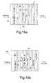
- FIGS. 6 and 7refer to a different embodiment of the device 10 , wherein the channel 4 has a deflection portion 21 connected to the inlet 4 a and two branch portions, including a waste branch portion 22 and a lysis/amplification portion 23 .
- Waste branch portion 22extends between the deflection portion 21 and a first outlet 4 b
- lysis/amplification portion 23extends between the deflection portion 21 and a second outlet 4 c.
- the electrodes 5are formed on the second wall 3 of the body 1 , while a group of counterelectrodes 20 is formed on the first wall 2 , opposite the electrodes 5 . Each counterelectrode 20 faces a respective electrode 5 .
- the electrodes 5can be individually biased by the control circuit 6 , while the counterelectrodes 20 are generally interconnected and left floating or grounded.
- the electrodes 5 and counterelectrodes 20are arranged along the deflection portion 21 and the lysis/amplification portion 23 , transversely thereto. Since the layout of the counterelectrodes 20 is the same as for the electrodes 5 , reference will be made hereinafter only to the electrodes 5 .
- the electrodes 5include three groups of electrodes 5 a , 5 b and 5 c .
- First electrodes 5 aare arranged in two sets, parallel to each other and transversely to the channel 4 , to form V shapes (hook-like structures), so as to increase the trapping capability.
- Second electrodes 5 bare arranged in the shape of a V along the beginning of the lysis/amplification portion 23 .
- Third electrodes 5 care arranged in the lysis/amplification portion 23 , downstream of the second electrodes 5 b , and are parallel to each other and to the lysis/amplification portion 23 .
- the electrodes 5 and the counterelectrodes 20are generally covered by a passivation layer, not shown here for sake of clarity and better described with reference to FIGS. 9-11 .
- the liquid including the mixture of target and the unwanted cellsis injected into the channel 4 through the inlet 4 a .
- the target cells 16are separated from the unwanted cells 16 in the deflection portion 21 and collected, e.g., between the counterelectrodes 20 and the V-shaped first and second electrodes 5 a , 5 b , by nDEP, while the unwanted cells 17 are washed out toward the first outlet 4 b through the waste branch portion 22 .
- the target cells 16are then released toward the lysis/amplification portion 23 , where they are lysed and amplified.
- FIG. 8shows a device 10 similar to device 10 of FIG. 7 , but including fourth electrodes 5 d having a zigzag shape in the deflection portion 21 , downstream of the first electrodes 5 a.
- FIG. 9is a top view of a portion of the channel 4 , showing a first layout of the electrodes 5 .
- the electrodes 5are formed by blank straight metal strips and the passivation layer 9 has an opening 15 just over the electrodes 5 .
- the target cells 16are attracted to the regions of high field, at the electrode edges.
- the passivation layer 9has a plurality of openings 15 stretching between and partly on top of two contiguous electrodes 5 , so that the passivation 9 does not cover the two facing halves of pairs of electrodes 5 .
- the target cells 16are attracted to the electrode edges that are not covered by the passivation (at the openings 15 ).
- the openings 15 in the passivation layer 9have circular shape and extend along each electrode 5 , near two facing edges of pairs of electrodes 5 .
- the target cells 16are attracted at the small openings 15 , where the field is maximum, as visible from FIG. 13 , showing the plot of the mean square electric field distribution.
- openings 15 in the passivation layer 9are advantageous because it allows reduced overall sample loss and heating. Furthermore, the openings 15 of small dimensions reduce the risk of clogging, because only few particles are trapped at each hole.
- FIGS. 14 a - 14 cshows another embodiment, wherein the device 10 includes electrodes 5 arranged on first wall 3 and counterelectrodes 20 arranged on second wall 2 of the device 10 .
- the electrodes 5 and the counterelectrodes 20are zigzag-shaped and are arranged facing each other.
- first the target cells 16here, white blood cells
- the unwanted cells 17here, red blood cells 17
- FIG. 14 cthe target cells 16 are lysed and change their behavior to pDEP.
- theyare attracted by both the electrodes 5 and the counterelectrodes 20 , where they can be further lysed and subjected to PCR.
- FIG. 20shows an embodiment similar to the one of FIG. 3 , wherein an array of detection electrodes 30 is formed in a different portion of the device 10 .
- the electrodes 30cooperate with biasing and control circuit 6 to perform an electric analysis of binding processes of analytes onto specially prepared electrodes.
- the detection electrodes 30are suitably prepared, e.g. gold electrodes are coated with stable organic compounds, wherein biomolecules, e.g. DNA or RNA probes, have been immobilized, as known in the art.
- the binding processcan be detected by impedance measurements performed through the biasing and control circuit 6 . In this way separation, lysis, amplification and detection can be carried out in a simple chip having only fluidic and electric connections, thus reducing cost and time for analysis.
- the devices 10 of FIGS. 3-20may be advantageously used to separate and detect white blood cells, as discussed in the examples given below.
- the device 10 of FIGS. 3 and 4was used for separating white blood cells using pDEP conditions.
- a diluted blood liquid (1:200, with a conductivity adjusted to 0.12 S/m)was injected in the inlet 4 a at a flow rate of 6 nl/s.
- the electrodeswere biased at an AC voltage having an amplitude of 8.5 V and a frequency of 5 MHz.
- Each electrode 5was biased in counterphase with respect to the adjacent electrodes.
- White blood cells 16were trapped at the electrodes 5 , while red blood cells 17 passed to the outlet 4 b almost unaffected, as visible from FIG. 15 showing a simulation of the electric field in a test device 10 .
- the devicewas drawn upside down with gravity g acting from below.
- FIG. 16shows the trapping of lysed white blood cells 16 .
- PCR reagentswere introduced in the device 10 and temperature cycles were applied.
- the temperature cyclesincluded a pre-denaturation cycle at 94° C. for 3 m; twelve cycles including denaturation at 94° C. for 40 s, annealing at 58° C. for 42 s, and extension at 72° C. for 45 s; then twenty-three cycles including denaturation at 94° C. for 40 s, annealing at 46° C. for 40 s, and extension at 72° C. for 45 s.
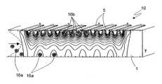
- White blood cells 16were trapped at the first wall 2 opposite to electrodes 5 , while red blood cells 17 passed to the outlet 4 b almost unaffected, as visible from FIG. 17 , showing an upside down device 10 , wherein white cells 16 a are shown trapped in minimum field position.
- a change of dielectrophoretic behaviour of the white blood cellswas observed.
- lysiswas accompanied by an increase of membrane conductivity resulting in a change from nDEP (curve a in FIG. 18 , showing the plot of the dielectrophoretic force as a function of the frequency of white blood cells) to pDEP behaviour (curve b) at moderate external conductivity (about 0.1 S/m).
- ion leakage decreasing internal conductivitywas observed (curves c and d in FIG. 18 ).
- FIG. 19 a , 19 billustrate the device viewed through a transparent upper wall 2 at two subsequent times and showing first nDEP (cells 16 a ) and then pDEP trapping (cells 16 b ).
Landscapes
- Engineering & Computer Science (AREA)
- Microelectronics & Electronic Packaging (AREA)
- Apparatus Associated With Microorganisms And Enzymes (AREA)
Abstract
Description
- This application claims priority to EP 05108445.7, filed Sep. 14, 2005, and is incorporated in its entirety herein by reference.
- Not applicable.
- Not applicable.
- The present invention relates to a method and device for the treatment of biological samples using dielectrophoresis.
- As is known, dielectrophoresis (DEP) is increasingly used in microchips to manipulate, identify, characterize and purify biological and artificial particles. DEP exploits frequency dependent differences in polarizability between the particles to be treated and the surrounding liquid that occur when RF (Radio Frequency) electric fields are applied thereto via microelectrodes.
- In case of biological particles, to which reference is made without losing generality, the microelectrodes can additionally be used to apply DC (Direct Current) voltage pulses of high amplitude (of the order of 100 V) for short times (of the order of microseconds) to destroy membrane integrity of dielectrophoretically captured cells, for later PCR-Polymerase Chain Reaction (see, e.g., U.S. Pat. No. 6,280,590). On the other hand, solid-phase PCR (on-chip PCR) has been developed for later detection of products, e.g. in microarray format already commercially available [see, e.g., http://www.vbc-genomics.com/on_chip_pcr.html and WO-A-93/22058).
- The theoretical background of DEP will be described herein below.
- If a time-periodic electric field is applied to a dielectric particle, the particle is subject to a dielectrophoretic force that is a function of the dielectric polarizability of the particle in the liquid, that is the difference between the tendencies of particle and of the liquid to respond to the applied electrical field. In particular, for a spherical dielectric particle of radius R subject to an electric time-periodic field E having a root-mean-square value {right arrow over (E)}rmsand angular frequency ω, the particle is subject to a dielectrophoretic force whose time averaged value{right arrow over (F)}d
 αν can be expressed using the dipole approximation as:
wherein εlis the liquid permittivity and fCMrepresents the above dielectric polarizability tendency, called the Clausius-Mossotti factor (see M. P. Hughes,Nanoelectromechanics in Engineering and Biology.2002: CRC Press, Boca Raton, Fla. 322 pp). For a homogeneous sphere suspended in a liquid, the Clausius-Mossotti factor has been found to be:
wherein σ represents the conductivity (the index p referring to the particle and the index l referring to the liquid) and ε is the absolute permittivity. - For a more complex particle, the effective particle conductivity σ has to be used; e.g., in case of a particle with spherical shape, formed by a shell (membrane) enclosing a different material in the interior, it reads:
wherein the indices i and m refer to particle interior and membrane, respectively, and a=R/R h for a membrane with thickness h. R is again the particle radius. FIG. 1 illustrates the relative dielectrophoretic force for lymphocytes (continuous line) and erythrocytes (broken lines) for media having three different conductivities. The dielectric spectra (ƒCM*R2) shifts to higher frequencies as conductivities rise and particles switch between positive DEP (pDEP, where the particles are attracted towards the electrodes), and negative DEP (nDEP, where the particles are repelled from the electrodes).- It has been already demonstrated (see Schnelle et al., “Paired microelectrode system: dielectrophoretic particle sorting and force calibration”, J. Electrostatics, 47/3, 121-132, 1999) that cells can be separated if they present different dielectrophoretic behaviour e.g. through different composition and/or size and/or shape, using equilibrium of flow (scaling with particle radius R) and DEP forces between face to face mounted electrode strips.
- If a particle showing nDEP at preset conditions is brought by streaming near an energised electrode pair, it is lifted to the central plane, experiencing repulsion forces from both electrodes.
FIG. 2 shows both equipotential and current lines between the electrode pair from the analytic solution for a semi-infinite plate capacitor. - Application of electric fields to conductive solutions is accompanied by heating. The balance equation for the temperature T reads:
wherein ρ is the liquid density, cpis the specific heat, λ is the thermal conductivity and ν is the velocity of the liquid. For example, for water, cp=4.18 kJ/(kg K), λ˜0.6 W/(m K). If ρcpνα<<1, the flow term in eq. 4 can be neglected (v<<4 mm/s in a channel with a height a=40 μm) and eq. 4 can be simplified to: - The time constant tdfor thermal equilibrium can be derived to be:
td=ρcpα2/λ (6)
which gives, for an aqueous solution and a=40 μm, td≅1 ms. - The stationary version of eq. 5 reads:
0=λΔT+σE2 (7) - According to a dimensional analysis, this gives an order of magnitude estimate for the temperature rise of:
∂T=σUrms2/λ (8)
wherein Urmsis the root mean square voltage applied between the electrodes. For an aqueous solutions with σ=1 S/m and a root mean square voltage Urms=5 V, eq. (8) results in T≅42° C. Thus physiological solutions can be heated up to boiling using moderate voltages. The absolute value of temperature depends on the electric field distribution and geometry, and can be usually obtained using numerical procedures. Quantitatively temperature rise is given by:
∂T=γσUrms2/λ (8a)
which wherein γ is a parameter depending on geometry of the system including the phase pattern of the voltage applied to electrodes. - In fact, eqs. (8) and (8a) underestimate the scaling at higher voltages. This is due to the fact the ohmic conductivity σ rises stronger then thermal conductivity λ:
σ(∂T)=σ0(1+α∂T) α˜0.022/K
λ(∂T)=λ0(1+β∂T) β˜0.002/K (9) - Taking eq. (9) into account, eq. (8a) results in:
∂T(U)=γσ0/λ0U2(1+Γσ0/λ0(α−β)U2+O(U4)) (10) - Although eq. 10 is only strictly true for homogenous systems, it gives a good estimate for sandwich systems as well.
- Based on the above, the object of the invention is to provide a highly efficient and low cost device and method for the manipulation of particles that allow reduction of overall diagnostic time and risk of contamination.
- The term “particle” used in the context of the invention is used in a general sense; it is not limited to individual biological cells. Instead, this term also includes generally synthetic or biological particles. Particular advantages result if the particles include biological materials, i.e. for example biological cells, cell groups, cell components or biologically relevant macromolecules, if applicable in combination with other biological particles or synthetic carrier particles. Synthetic particles can include solid particles, liquid particles or multiphase particles which are delimited from the suspension medium, which particles constitute a separate phase in relation to the suspension medium, i.e. the carrier liquid.
- In particular, the invention is advantageously applicable for biological particles, especially for integrated cell separation, lysis and amplification from blood or other cell suspensions.
- According to the present invention, there are provided a method and a device for the treatment of biological samples, as defined in
claims 1 and28, respectively. - For the understanding of the present invention, a preferred embodiment is now described, purely as a non-limiting example, with reference to the enclosed drawings, wherein:
FIG. 1 illustrates the relative dielectrophoretic force for lymphocytes and erythrocytes, at three different medium conductivities.FIG. 2 shows a cross-section of an electrode pair of a capacitor and the existing electrical field.FIG. 3 shows a cross-section of a device for performing treatment of biological samples, according to a first embodiment of the present invention.FIG. 4 shows a top plan view of the device ofFIG. 3 .FIG. 5 shows a top plan view of a second embodiment of the present device.FIG. 6 shows a cross-section of a different device, according to a third embodiment of the present invention.FIG. 7 shows a top plan view of the device ofFIG. 6 .FIG. 8 shows a top plan view of a fourth embodiment of the present device.FIGS. 9-11 are top views of alternative layouts of details of the devices ofFIGS. 3-8 .FIGS. 12 and 13 are a top view and a cross-section of a detail ofFIG. 11 , during a separation step.FIG. 14 ais a top view of a further embodiment of the present device.FIGS. 14 band14care cross sections of the device ofFIG. 14 a, at two subsequent times.FIG. 15 shows a three-dimensional simulation of the electric field applied to the device ofFIG. 3 in a first working condition.FIG. 16 shows the result of the separation and lysis treatment in the device ofFIG. 15 .FIG. 17 shows a three-dimensional simulation of the electric field applied to the device ofFIG. 3 in a second working condition.FIG. 18 is a plot of electrical quantities for the device ofFIG. 17 .FIGS. 19 aand19bare top views of the device ofFIG. 17 , showing the behavior of particles during separation and lysis, at two subsequent times.FIG. 20 shows a cross-section of a different embodiment of the present invention.- According to one embodiment of the invention, a plurality of planar electrodes in a microchannel are used for separation, lysis and amplification in a chip. Cells from a sample are brought to a first group or array of electrodes. Depending on sample properties, phase pattern, frequency and voltage of the first array of electrodes and flow velocity are chosen to repel/trap target cells (for example, white blood cells or bacteria) using nDEP in regions of low electric field in the fluid between the first group of electrodes and their counterelectrodes, whereas majority of unwanted cells flush through. In the alternative, pDEP is used to trap the target cells near the electrodes. Separation of red blood cells and white blood cells is comparatively easy because the larger white blood cells experience larger relative DEP forces (DEP force versus hydrodynamic force).
- During or after separation, target cells are trapped at the same or a second group of electrodes. This can be achieved by switching the frequency of the first group of electrodes to a frequency of pDEP (e.g. from kHz range to lower MHz range for modeled lymphocytes) or switching off the first group of electrodes whilst the second group of electrodes is energized for pDEP. Dielectric properties of the trapped cells can be changed by RF and/or thermal or chemical lysis. The changed cells can be further manipulated (separation/trapping) by nDEP or pDEP at a second group of electrodes.
- In a further alternative embodiment, the unwanted cells are first trapped or deflected by pDEP or nDEP using a first electrode array biased at a frequency while the target cells are flushed through. The target cells are then trapped and treated as described above using the same frequency or another frequency on a second electrode array.
- To minimize clogging, the electrodes of an array or group can be driven according to predefined (depending on flow velocity) or feedback-controlled time regime such that the groups of electrodes are filled with target cells sequentially. This can be achieved by first switching on the electrodes that are the furthest from the device input (most downstream electrodes). Then, when these electrodes are filled, the electrodes that are immediately upstream are energized, and so on. Here, passivated electrodes with small openings in the passivating layer can be used.
- The trapped particles are then lysed to release the information carriers contained therein. The term “information carrier” employed in the context of the invention is used in a general sense, it is not limited to RNA and DNA, it also includes proteins or modified oligonucleotides.
- Electric field mediated cell lysis is based on induction of an additional transmembrane potential (TMP) which oscillates with the external field. Its absolute value is approximately given by:
with a time constant τ mainly depending on membrane capacity τ˜εm/d. It drops sharply with frequency (ω=2πf) and is superimposed to the permanent transmembrane potential (pTMP) of about 100 mV resulting from cell charging. When the transmembrane potential exceeds values of about 1 V, membrane breakdown occurs. This results in an increase of membrane conductivity and subsequently change of cell interior. As a consequence, cells originally showing nDEP behaviour are attracted to the electrodes of the same or second group of electrodes. Additionally, the cells can be further lysed either by RF fields or thermally (higher field values near electrodes) or using additional DC high voltage pulses. - Particles can be considered as dielectric bodies consisting of different layers with different electrical properties (Fuhr, G., Müller, T., Hagedorn, R., 1989. Reversible and irreversible rotating field-induced membrane modifications.Biochim. Biophys. Acta980: 1-8). Thus it is possible to lyse first the nuclear membrane with higher frequencies, and then the outer cell membrane.
- In general, particles can be considered as homogeneous spheres, single- or multi-shell models. For example, a cell with cell nucleus can be considered as 3-shell model, wherein the first layer is the outer membrane, the second layer is cytoplasm, the third layer is the nuclear membrane, and the three layers surround the nuclear body. The electrical loading of the outer membrane decreases with increasing field frequency. In contrast to the behaviour of the outer membrane, the electrical loading of the inner membrane is low at lower frequencies, increases with rising frequencies and decreases again at high frequencies (see Fuhr, G., Müller, T., Hagedorn, R., 1989. Reversible and irreversible rotating field-induced membrane modifications.Biochim. Biophys. Acta980: 1-8, Fig. 3). The dielectric properties (permittivity, conductivity and thickness) of each layer determines the value of the induced transmembrane potentials. Increasing the conductivity of the outer membrane increases the height of the induced transmembrane potential of the inner membrane.
- After lysis, the information carriers are separated from the unwanted lysis products e.g. by flow and dielectrophoresis. In particular, the information carriers are transported to an amplification (PCR) region and/or amplification (PCR) reagents are brought to the electrodes holding the information carriers so as to amplify them. Thermocycling is done using buried elements or using the same trapping electrodes, applying appropriate voltages to realize the required temperature sequences. Beside simplicity, the latter solution has the advantage of faster ramps (down to ms) due to very small heated volumes.
- In a further embodiment, the products of amplification can be analysed at a further electrode array e.g. by electric analysis of binding processes of analytes onto specially prepared electrodes. Suitable preparation of electrodes (e.g. coating of gold electrodes by stable organic compounds and further immobilization of biomolecules e.g. DNA or RNA probes) is state of the art and compatible with CMOS technology, see e.g. Hoffman et al., http://www.imec.be/essderc/ESSDERC2002/PDFs/D24—3.pdf).
- The binding process can be detected by impedance measurements that have been shown to be sensitive enough to detect molecular events (Karolis et al., Biochimica et Biophysica Acta, 1368, 247-255, 1998). In this way separation, lysis, amplification and detection can be carried out in a simple chip having only fluidic and electric connections, thus reducing cost and time for analysis.
- Alternatively, direct analyte detection can be carried out using voltmetric or amperiometric methods (see e.g. Hoffmann et al. or Bard & Fan,Acc. Chem. Res.1996, 29, 572-578) not requiring surface coating of electrodes. In this case, the same electrodes as used for trapping and or lysis can be used.
- Experiments revealed that RF lysed cells remain stably trapped at the electrodes after switching off the field. DC pulses can afterwards be used for additional lysis but also to remove the lysis products if PCR is carried out further downstream. Compared to DC pulses, RF fields have the advantage of minimizing (avoiding) electrochemical reactions at the electrodes (e.g. electrolysis). Further, they better penetrate the cell interior. This is of importance since not only the cell membrane but also the membrane of the nucleus has to be disintegrated. PCR with RF lysed cells was successful without additional DC pulses allowing simplification of electronics and shielding.
FIGS. 3 and 4 show an implementation of adevice 10 intended to treat biological samples including mixture of target particles and other particles. In particular, thedevice 10 ofFIGS. 3 and 4 is suitable for separating and amplifying white blood cells, but may also be used for selecting and treating red blood cells (e.g. for detecting special diseases, e.g. malaria, or for carrying out prenatal diagnostic purposes) or for detecting migrating tumor cells or bacteria.- The
device 10 ofFIGS. 3 and 4 is formed in a chip, e.g. of silicon or glass, comprising abody 1 having afirst wall 2 and asecond wall 3 enclosing amain channel 4 filled by a liquid injected from aninlet 4aof the channel and including both target cells and unwanted cells (waste). Thechannel 4 has also anoutlet 4bfor discharging the unwanted cells as well as the target cells, at the end of the treatment. Electrodes 5 are formed on thesecond wall 3 and are connected to a biasing andcontrol circuit 6, shown only schematically, for applying electric pulses to theelectrodes 5 and possibly for detection purposes. The electrodes are biased by applying a single or double-phase RF voltage. If the chip comprising thebody 1 is of silicon, the biasing andcontrol circuit 6 may be integrated in the same chip. Theelectrodes 5 are planar electrodes formed by straight metal elements, that are arranged here parallel to each other and perpendicular to thechannel 4, and are generally covered by apassivation layer 9. In the alternative, theelectrodes 5 may be formed by blank electrode strips.- The
body 1 is connected to apump 7, here shown upstream of thechannel 4, for injecting the liquid to be treated from aliquid source 8 into theinlet 4aof thechannel 4. Furthermore, areagent source 11 is also connected to theinlet 4aof thechannel 4 for injections of reagents during PCR. In the alternative, thepump 7 could be connected to theoutlet 4bto suck the liquid and the reagents out of therespective sources channel 4 and being treated therein. In this case, a valve structure may be needed between thereagent source 11 andinlet 4ato control injection. - In any case, the liquid that flows through the
channel 4 is subject to a hydrodynamic force, represented here by arrows, drawing the liquid from theinlet 4atowards theoutlet 4b. Thepump 7 may be integrated in a single chip asbody 1, e.g. as taught in EP-A-1 403 383. - With reference to
FIGS. 3 and 4 , a liquid (e.g., 1-10 μl) comprising a mixture of target cells (16 inFIG. 4 ) and undesired cells (17 inFIG. 4 ) is injected into thechannel 4 from theliquid source 8 through theinlet 4a. Theelectrodes 5 are biased so that each electrode is in counterphase with respect to the adjacent electrodes. For example, the electrodes are biased by applying an AC voltage with an amplitude of 1-10 V and a frequency of between 300 KHz and 10 MHz. pDEP or nDEP may be used. If pDEP is used, thetarget cells 16 are attracted to theelectrodes 5, while theunwanted cells 17 are washed out through theoutlet 4b. If nDEP is used, thetarget cells 16 are repelled from theelectrodes 5 toward thefirst wall 2. - Then, the
target cells 16 are lysed, either electrically (through application of a DC field or an RF field), chemically or biochemically (through introduction of a lysis reagent), and/or thermally. DC lysis may performed by applying pulses having amplitude of 20-200 V, width of 5-100 μs, and a repetition frequency of 0.1-10 Hz for 1-60 s. AC lysis may performed by applying an AC voltage having amplitude of 3-20V and a frequency of between 10 kHz and 100 MHz. Chemical or biochemical lysis may be performed using known protocols. Thermal lysis may be performed at 45-70° C. Lysis can also be monitored using a fluorescent marker e.g. calcein. - Then, with the lysed
target cells 16 trapped against thesame trapping electrodes 5 or subsequent suitablybiased electrodes 5 arranged downstream of the trapping electrodes, PCR is brought about by introducing a reagent liquid (including polymerase) and carrying out a thermal cycle (thermocyclying) so as to amplify the released information carriers (DNA, RNA or proteins). - The
electrodes 5 can be used also for detection, using voltmetric or amperiometric methods. In this case, the biasing andcontrol circuit 6 also comprises the components necessary for generating the needed test currents/voltages and the measuring components and software. FIG. 5 shows the top view of another embodiment of thedevice 10 wherein areagent channel 25 having aninlet 25ais formed directly in thebody 1, to allow injection of the reagents for chemical lysis and/or PCR. Otherwise, thedevice 10 ofFIG. 5 is the same as ofFIGS. 3 and 4 .FIGS. 6 and 7 refer to a different embodiment of thedevice 10, wherein thechannel 4 has adeflection portion 21 connected to theinlet 4aand two branch portions, including awaste branch portion 22 and a lysis/amplification portion 23.Waste branch portion 22 extends between thedeflection portion 21 and afirst outlet 4b, and lysis/amplification portion 23 extends between thedeflection portion 21 and asecond outlet 4c.- The
electrodes 5 are formed on thesecond wall 3 of thebody 1, while a group of counterelectrodes20 is formed on thefirst wall 2, opposite theelectrodes 5. Eachcounterelectrode 20 faces arespective electrode 5. Theelectrodes 5 can be individually biased by thecontrol circuit 6, while thecounterelectrodes 20 are generally interconnected and left floating or grounded. - In the embodiment shown in
FIGS. 6 and 7 , theelectrodes 5 andcounterelectrodes 20 are arranged along thedeflection portion 21 and the lysis/amplification portion 23, transversely thereto. Since the layout of thecounterelectrodes 20 is the same as for theelectrodes 5, reference will be made hereinafter only to theelectrodes 5. - For example, here the
electrodes 5 include three groups ofelectrodes First electrodes 5aare arranged in two sets, parallel to each other and transversely to thechannel 4, to form V shapes (hook-like structures), so as to increase the trapping capability.Second electrodes 5bare arranged in the shape of a V along the beginning of the lysis/amplification portion 23.Third electrodes 5care arranged in the lysis/amplification portion 23, downstream of thesecond electrodes 5b, and are parallel to each other and to the lysis/amplification portion 23. - The
electrodes 5 and thecounterelectrodes 20 are generally covered by a passivation layer, not shown here for sake of clarity and better described with reference toFIGS. 9-11 . - Also here, the liquid including the mixture of target and the unwanted cells is injected into the
channel 4 through theinlet 4a. Thetarget cells 16 are separated from theunwanted cells 16 in thedeflection portion 21 and collected, e.g., between the counterelectrodes20 and the V-shaped first andsecond electrodes unwanted cells 17 are washed out toward thefirst outlet 4bthrough thewaste branch portion 22. Thetarget cells 16 are then released toward the lysis/amplification portion 23, where they are lysed and amplified. FIG. 8 shows adevice 10 similar todevice 10 ofFIG. 7 , but includingfourth electrodes 5dhaving a zigzag shape in thedeflection portion 21, downstream of thefirst electrodes 5a.FIG. 9 is a top view of a portion of thechannel 4, showing a first layout of theelectrodes 5. Here, theelectrodes 5 are formed by blank straight metal strips and thepassivation layer 9 has anopening 15 just over theelectrodes 5. Here, during trapping by pDEP, thetarget cells 16 are attracted to the regions of high field, at the electrode edges.- In the embodiment of
FIG. 10 , thepassivation layer 9 has a plurality ofopenings 15 stretching between and partly on top of twocontiguous electrodes 5, so that thepassivation 9 does not cover the two facing halves of pairs ofelectrodes 5. In this case, during trapping by pDEP, thetarget cells 16 are attracted to the electrode edges that are not covered by the passivation (at the openings15). - In the embodiment of
FIG. 11 , theopenings 15 in thepassivation layer 9 have circular shape and extend along eachelectrode 5, near two facing edges of pairs ofelectrodes 5. - Here, as shown in the enlarged detail of
FIG. 12 , during trapping by pDEP, thetarget cells 16 are attracted at thesmall openings 15, where the field is maximum, as visible fromFIG. 13 , showing the plot of the mean square electric field distribution. - The use of
circular openings 15 in thepassivation layer 9 is advantageous because it allows reduced overall sample loss and heating. Furthermore, theopenings 15 of small dimensions reduce the risk of clogging, because only few particles are trapped at each hole. FIGS. 14 a-14cshows another embodiment, wherein thedevice 10 includeselectrodes 5 arranged onfirst wall 3 andcounterelectrodes 20 arranged onsecond wall 2 of thedevice 10. Theelectrodes 5 and thecounterelectrodes 20 are zigzag-shaped and are arranged facing each other. As shown in the top view ofFIG. 14 aand in the cross-section ofFIG. 14 b, first the target cells16 (here, white blood cells) are retarded and trapped by nDEP in the space betweenelectrodes 5 andcounterelectrodes 20, while the unwanted cells17 (here, red blood cells17) flow through, towards theoutlet 4b. Then inFIG. 14 c, thetarget cells 16 are lysed and change their behavior to pDEP. Thus, they are attracted by both theelectrodes 5 and thecounterelectrodes 20, where they can be further lysed and subjected to PCR.FIG. 20 shows an embodiment similar to the one ofFIG. 3 , wherein an array ofdetection electrodes 30 is formed in a different portion of thedevice 10. Theelectrodes 30 cooperate with biasing andcontrol circuit 6 to perform an electric analysis of binding processes of analytes onto specially prepared electrodes. To this end, thedetection electrodes 30 are suitably prepared, e.g. gold electrodes are coated with stable organic compounds, wherein biomolecules, e.g. DNA or RNA probes, have been immobilized, as known in the art. The binding process can be detected by impedance measurements performed through the biasing andcontrol circuit 6. In this way separation, lysis, amplification and detection can be carried out in a simple chip having only fluidic and electric connections, thus reducing cost and time for analysis.- The
devices 10 ofFIGS. 3-20 may be advantageously used to separate and detect white blood cells, as discussed in the examples given below. - The
device 10 ofFIGS. 3 and 4 was used for separating white blood cells using pDEP conditions. To this end, a diluted blood liquid (1:200, with a conductivity adjusted to 0.12 S/m) was injected in theinlet 4aat a flow rate of 6 nl/s. The electrodes were biased at an AC voltage having an amplitude of 8.5 V and a frequency of 5 MHz. Eachelectrode 5 was biased in counterphase with respect to the adjacent electrodes.White blood cells 16 were trapped at theelectrodes 5, whilered blood cells 17 passed to theoutlet 4balmost unaffected, as visible fromFIG. 15 showing a simulation of the electric field in atest device 10. InFIG. 15 , the device was drawn upside down with gravity g acting from below. - Then the trapped blood cells were electrically lysed by applying DC pulses (with amplitude 131 V,
duration 20 μs and repetition frequency of 0.5 Hz).FIG. 16 shows the trapping of lysedwhite blood cells 16. - Next PCR reagents were introduced in the
device 10 and temperature cycles were applied. In particular, the PCR reagents are shown in Table 1, and the temperature cycles included a pre-denaturation cycle at 94° C. for 3 m; twelve cycles including denaturation at 94° C. for 40 s, annealing at 58° C. for 42 s, and extension at 72° C. for 45 s; then twenty-three cycles including denaturation at 94° C. for 40 s, annealing at 46° C. for 40 s, and extension at 72° C. for 45 s.TABLE 1 Preparation of PCR master mix to be added to 1 μl sample Master Mix Pure water 10 μl Sigma 2× Mix* 15 μl Primer 1** 1.5 μl Primer 2 1.5 μl Total Volume 28 μl
*Sigma Extract-N-Amp ™ Blood PCR Kit (Sigma ™ cat. No XNAB2R Lot 91K9295)
**Primers (MLH-1, 3′ and 5′ primer, Evotec Technologies ™) - The results are not shown, but successful cell separation, lysis and amplification was achieved.
- The
device 10 ofFIGS. 3 and 4 was used for separating white blood cells using nDEP conditions for white blood cells. To this end, a diluted blood liquid having the same composition as in the first test was injected in adevice 10, wherein the electrodes were biased at A=8.5 V, f=320 MHz. White blood cells 16 were trapped at thefirst wall 2 opposite toelectrodes 5, whilered blood cells 17 passed to theoutlet 4balmost unaffected, as visible fromFIG. 17 , showing an upside downdevice 10, whereinwhite cells 16aare shown trapped in minimum field position.- Then, the trapped white blood cells were electrically lysed by applying an RF voltage to a second group of electrodes5 (A=11 V, f=320 kHz). In particular, during this phase, a change of dielectrophoretic behaviour of the white blood cells was observed. In fact lysis was accompanied by an increase of membrane conductivity resulting in a change from nDEP (curve a in
FIG. 18 , showing the plot of the dielectrophoretic force as a function of the frequency of white blood cells) to pDEP behaviour (curve b) at moderate external conductivity (about 0.1 S/m). Then ion leakage decreasing internal conductivity was observed (curves c and d inFIG. 18 ). Trapping and lysis ofwhite blood cells 16 is also visible fromFIG. 19 a,19b, which illustrate the device viewed through a transparentupper wall 2 at two subsequent times and showing first nDEP (cells 16a) and then pDEP trapping (cells 16b). - Thereafter, the lysed cells were subject to amplification as discussed in example 1. Results are not shown, but successful amplification was achieved.
- The advantages of the present invention are clear from the above. In particular, implementation of a single microdevice for particle separation, lysis and amplification allows reduction of the overall diagnostic time and risk of contamination. Furthermore, samples of smaller volumes can be used, thus further reducing the diagnostic costs, and the risk of sample loss due to fluid transfer needs is eliminated.
- Finally, it is clear that numerous variations and modifications may be made to the device and process described and illustrated herein, all falling within the scope of the invention as defined in the attached claims.


Claims (39)
Applications Claiming Priority (3)
| Application Number | Priority Date | Filing Date | Title |
|---|---|---|---|
| EPEP05108445.7 | 2005-09-14 | ||
| EP05108445 | 2005-09-14 | ||
| EP05108445AEP1764418B1 (en) | 2005-09-14 | 2005-09-14 | Method and device for the treatment of biological samples using dielectrophoresis |
Publications (2)
| Publication Number | Publication Date |
|---|---|
| US20070125650A1true US20070125650A1 (en) | 2007-06-07 |
| US7988841B2 US7988841B2 (en) | 2011-08-02 |
Family
ID=36130009
Family Applications (1)
| Application Number | Title | Priority Date | Filing Date |
|---|---|---|---|
| US11/531,679Active2029-06-17US7988841B2 (en) | 2005-09-14 | 2006-09-13 | Treatment of biological samples using dielectrophoresis |
Country Status (2)
| Country | Link |
|---|---|
| US (1) | US7988841B2 (en) |
| EP (1) | EP1764418B1 (en) |
Cited By (27)
| Publication number | Priority date | Publication date | Assignee | Title |
|---|---|---|---|---|
| US20090038938A1 (en)* | 2007-05-10 | 2009-02-12 | The Regents Of The University Of California | Microfluidic central processing unit and microfluidic systems architecture |
| WO2009151407A2 (en) | 2008-06-14 | 2009-12-17 | Veredus Laboratories Pte Ltd | Influenza sequences |
| WO2009146143A3 (en)* | 2008-04-03 | 2010-03-04 | The Regents Of The University Of California | Ex-vivo multi-dimensional system for the separation and isolation of cells, vesicles, nanoparticles and biomarkers |
| US20110100820A1 (en)* | 2008-05-23 | 2011-05-05 | Iti Scotland Limited | Triple function electrodes |
| US20110139621A1 (en)* | 2009-08-13 | 2011-06-16 | Michael Stumber | Microfluidic cell |
| US20110139620A1 (en)* | 2009-08-13 | 2011-06-16 | Michael Stumber | Microfluidic cell |
| US20110259745A1 (en)* | 2010-04-22 | 2011-10-27 | Dehlinger Dietrich A | Three Dimensional Microelectrode System For Dielectrophoresis |
| US20130105317A1 (en)* | 2011-10-31 | 2013-05-02 | Monika Weber | Electronic Device for Pathogen Detection |
| US8603791B2 (en) | 2012-04-16 | 2013-12-10 | Biological Dynamics, Inc. | Nucleic acid sample preparation |
| US20130340806A1 (en)* | 2011-01-27 | 2013-12-26 | Hitachi Chemical Company, Ltd. | Electrically conductive adhesive composition, connector and solar cell module |
| US20140315195A1 (en)* | 2011-05-24 | 2014-10-23 | The Regents Of The University Of California | Method for exosomal biomarker detection by electric field-induced release and measurement |
| US8932815B2 (en) | 2012-04-16 | 2015-01-13 | Biological Dynamics, Inc. | Nucleic acid sample preparation |
| US20150152556A1 (en)* | 2011-08-02 | 2015-06-04 | Tokyo Electron Limited | Method and device for controlling pattern and structure formation by an electric field |
| US9387489B2 (en) | 2014-04-08 | 2016-07-12 | Biological Dynamics, Inc. | Devices for separation of biological materials |
| US20180093271A1 (en)* | 2016-09-30 | 2018-04-05 | The University Of Tokyo | Microdevice for Capturing Particles, and Method for Capturing, Concentrating, or Separating Particles Using the Same |
| US10232369B2 (en) | 2016-03-24 | 2019-03-19 | Biological Dynamics, Inc. | Disposable fluidic cartridge and components |
| US10413913B2 (en) | 2017-02-15 | 2019-09-17 | Tokyo Electron Limited | Methods and systems for dielectrophoresis (DEP) separation |
| WO2020169045A1 (en)* | 2019-02-19 | 2020-08-27 | MicroMED Co., Ltd. | Micro-delivery device |
| US10818379B2 (en) | 2017-05-08 | 2020-10-27 | Biological Dynamics, Inc. | Methods and systems for analyte information processing |
| US11072810B2 (en) | 2019-11-13 | 2021-07-27 | Fluid-Screen, Inc. | Apparatus and methods to rapidly detect, separate, purify, and quantify various viruses from cells, cultured medium and other fluids |
| US11193101B2 (en) | 2019-11-13 | 2021-12-07 | Fluid-Screen, Inc. | Methods and apparatus for separating live from dead organisms in a sample |
| US11198126B2 (en) | 2011-10-31 | 2021-12-14 | Fluid-Screen, Inc. | Apparatus for pathogen detection |
| US11198139B2 (en) | 2016-04-15 | 2021-12-14 | Fluid-Screen, Inc. | Analyte detection methods and apparatus using dielectrophoresis and electroosmosis |
| US11376640B2 (en) | 2018-10-01 | 2022-07-05 | Tokyo Electron Limited | Apparatus and method to electrostatically remove foreign matter from substrate surfaces |
| US11731132B2 (en) | 2017-12-19 | 2023-08-22 | Biological Dynamics, Inc. | Methods and devices for detection of multiple analytes from a biological sample |
| US11883833B2 (en) | 2018-04-02 | 2024-01-30 | Biological Dynamics, Inc. | Dielectric materials |
| WO2024025100A1 (en)* | 2022-07-28 | 2024-02-01 | 삼성전자 주식회사 | Fine particle filter device, fine particle filter method and washing machine comprising same |
Families Citing this family (17)
| Publication number | Priority date | Publication date | Assignee | Title |
|---|---|---|---|---|
| EP2010323B1 (en)* | 2006-04-10 | 2012-11-14 | Technion Research and Development of Foundation, Ltd. | Method and device for electrokinetic manipulation |
| CN101059526B (en)* | 2007-05-24 | 2011-04-20 | 上海交通大学 | Method for driving fluid movement in micropassage using electric heat flow |
| WO2009037804A1 (en)* | 2007-09-18 | 2009-03-26 | Panasonic Corporation | Microparticle measuring device and microparticle measuring method |
| KR100947334B1 (en) | 2008-01-30 | 2010-03-16 | 인제대학교 산학협력단 | Dielectrophoretic Micro Separator |
| US20110192726A1 (en)* | 2008-10-31 | 2011-08-11 | Agency For Science ,Technology And Research | Device and method for detection of analyte from a sample |
| JP5867920B2 (en) | 2009-02-20 | 2016-02-24 | 国立研究開発法人科学技術振興機構 | Transport of micro-sized objects and extraction of mechanical work by constant electric field |
| MY179484A (en)* | 2011-08-24 | 2020-11-08 | Mimos Bhd | Apparatus for sorting particles by dielectrophoresis |
| KR101356460B1 (en)* | 2012-02-08 | 2014-02-04 | 서울대학교산학협력단 | Particle Separation Device and method of separating particle from solution using the same |
| US9981273B2 (en) | 2012-09-28 | 2018-05-29 | The Board Of Trustees Of The Leland Stanford Junior University | Negative dielectrophoresis for selective elution of immuno-bound particles |
| US9683253B2 (en)* | 2013-03-19 | 2017-06-20 | Imec | Method and device for identifying cells |
| TWI472756B (en)* | 2013-12-11 | 2015-02-11 | Nat Applied Res Laboratories | A biochip device and a method of separating and concentrating particles in a fluid |
| US10081015B2 (en) | 2015-07-12 | 2018-09-25 | International Business Machines Corporation | Trapping at least one microparticle |
| US9962714B2 (en)* | 2015-07-12 | 2018-05-08 | International Business Machines Corporation | Microchannel, microfluidic chip and method for processing microparticles in a fluid flow |
| US11543402B2 (en) | 2017-10-19 | 2023-01-03 | Analog Devices, Inc. | Impedance measurement in diagnostic testing |
| WO2020141526A1 (en)* | 2018-12-31 | 2020-07-09 | Technion Research & Development Foundation Limited | Apparatus and method for sorting cells in a biological sample |
| WO2020174403A1 (en)* | 2019-02-26 | 2020-09-03 | Moshe Giladi | Determining a frequency for ttfields treatment based on an electrical characteristic of targeted cancer cells |
| KR102671385B1 (en)* | 2021-06-04 | 2024-05-31 | 국립창원대학교 산학협력단 | Microparticle collection apparatus using dielectriphoresis |
Citations (8)
| Publication number | Priority date | Publication date | Assignee | Title |
|---|---|---|---|---|
| US6071394A (en)* | 1996-09-06 | 2000-06-06 | Nanogen, Inc. | Channel-less separation of bioparticles on a bioelectronic chip by dielectrophoresis |
| US6235471B1 (en)* | 1997-04-04 | 2001-05-22 | Caliper Technologies Corp. | Closed-loop biochemical analyzers |
| US20020036142A1 (en)* | 2000-06-14 | 2002-03-28 | Peter Gascoyne | Systems and methods for cell subpopulation analysis |
| US20020088712A1 (en)* | 2001-01-09 | 2002-07-11 | The Regents Of The University Of California | Movement of particles using sequentially activated dielectrophoretic particle trapping |
| US20040011650A1 (en)* | 2002-07-22 | 2004-01-22 | Frederic Zenhausern | Method and apparatus for manipulating polarizable analytes via dielectrophoresis |
| US6727451B1 (en)* | 1998-04-08 | 2004-04-27 | Evotec Technologies Gmbh | Method and device for manipulating microparticles in fluid flows |
| US6749736B1 (en)* | 1998-06-26 | 2004-06-15 | Evotec Technologies Gmbh | Electrode arrangement for the dielectrophoretic diversion of particles |
| US6783647B2 (en)* | 2001-10-19 | 2004-08-31 | Ut-Battelle, Llc | Microfluidic systems and methods of transport and lysis of cells and analysis of cell lysate |
Family Cites Families (2)
| Publication number | Priority date | Publication date | Assignee | Title |
|---|---|---|---|---|
| WO1993022053A1 (en) | 1992-05-01 | 1993-11-11 | Trustees Of The University Of Pennsylvania | Microfabricated detection structures |
| ITTO20020809A1 (en)* | 2002-09-17 | 2004-03-18 | St Microelectronics Srl | MICROPUMP, IN PARTICULAR FOR AN INTEGRATED DNA ANALYSIS DEVICE. |
- 2005
- 2005-09-14EPEP05108445Apatent/EP1764418B1/ennot_activeExpired - Lifetime
- 2006
- 2006-09-13USUS11/531,679patent/US7988841B2/enactiveActive
Patent Citations (10)
| Publication number | Priority date | Publication date | Assignee | Title |
|---|---|---|---|---|
| US6071394A (en)* | 1996-09-06 | 2000-06-06 | Nanogen, Inc. | Channel-less separation of bioparticles on a bioelectronic chip by dielectrophoresis |
| US6280590B1 (en)* | 1996-09-06 | 2001-08-28 | Nanogen, Inc. | Channel-less separation of bioparticles on a bioelectronic chip by dielectrophoresis |
| US6235471B1 (en)* | 1997-04-04 | 2001-05-22 | Caliper Technologies Corp. | Closed-loop biochemical analyzers |
| US6403338B1 (en)* | 1997-04-04 | 2002-06-11 | Mountain View | Microfluidic systems and methods of genotyping |
| US6727451B1 (en)* | 1998-04-08 | 2004-04-27 | Evotec Technologies Gmbh | Method and device for manipulating microparticles in fluid flows |
| US6749736B1 (en)* | 1998-06-26 | 2004-06-15 | Evotec Technologies Gmbh | Electrode arrangement for the dielectrophoretic diversion of particles |
| US20020036142A1 (en)* | 2000-06-14 | 2002-03-28 | Peter Gascoyne | Systems and methods for cell subpopulation analysis |
| US20020088712A1 (en)* | 2001-01-09 | 2002-07-11 | The Regents Of The University Of California | Movement of particles using sequentially activated dielectrophoretic particle trapping |
| US6783647B2 (en)* | 2001-10-19 | 2004-08-31 | Ut-Battelle, Llc | Microfluidic systems and methods of transport and lysis of cells and analysis of cell lysate |
| US20040011650A1 (en)* | 2002-07-22 | 2004-01-22 | Frederic Zenhausern | Method and apparatus for manipulating polarizable analytes via dielectrophoresis |
Cited By (60)
| Publication number | Priority date | Publication date | Assignee | Title |
|---|---|---|---|---|
| US20090038938A1 (en)* | 2007-05-10 | 2009-02-12 | The Regents Of The University Of California | Microfluidic central processing unit and microfluidic systems architecture |
| GB2468226B (en)* | 2008-04-03 | 2011-06-01 | Univ California | Ex-vivo multi dimensional system for the separation and isolation of cells, vesicles, nanoparticles and biomarkers |
| US8932447B2 (en) | 2008-04-03 | 2015-01-13 | The Regents Of The University Of California | Ex-vivo multi-dimensional system for the separation and isolation of cells, vesicles, nanoparticles, and biomarkers |
| WO2009146143A3 (en)* | 2008-04-03 | 2010-03-04 | The Regents Of The University Of California | Ex-vivo multi-dimensional system for the separation and isolation of cells, vesicles, nanoparticles and biomarkers |
| GB2468226A (en)* | 2008-04-03 | 2010-09-01 | Univ California | Ex-vivo multi dimensional system for the separation and isolation of cells, vesicles, nanoparticles and biomarkers |
| CN102037351A (en)* | 2008-04-03 | 2011-04-27 | 加利福尼亚大学董事会 | Ex vivo multidimensional systems for separating and isolating cells, vesicles, nanoparticles, and biomarkers |
| US20110108422A1 (en)* | 2008-04-03 | 2011-05-12 | The Regents Of The University Of California | Ex vivo multi-dimensional system for the separation and isolation of cells, vesicles, nanoparticles and biomarkers |
| JP2011516867A (en)* | 2008-04-03 | 2011-05-26 | ザ レジェンツ オブ ザ ユニヴァースティ オブ カリフォルニア | An ex vivo multidimensional system for separating and isolating cells, vesicles, nanoparticles and biomarkers |
| US20110100820A1 (en)* | 2008-05-23 | 2011-05-05 | Iti Scotland Limited | Triple function electrodes |
| WO2009151407A2 (en) | 2008-06-14 | 2009-12-17 | Veredus Laboratories Pte Ltd | Influenza sequences |
| US20110139621A1 (en)* | 2009-08-13 | 2011-06-16 | Michael Stumber | Microfluidic cell |
| US20110139620A1 (en)* | 2009-08-13 | 2011-06-16 | Michael Stumber | Microfluidic cell |
| US9034162B2 (en)* | 2009-08-13 | 2015-05-19 | Robert Bosch Gmbh | Microfluidic cell |
| US20110259745A1 (en)* | 2010-04-22 | 2011-10-27 | Dehlinger Dietrich A | Three Dimensional Microelectrode System For Dielectrophoresis |
| US8524064B2 (en)* | 2010-04-22 | 2013-09-03 | Lawrence Livermore National Security, Llc | Three dimensional microelectrode system for dielectrophoresis |
| US20130306481A1 (en)* | 2010-04-22 | 2013-11-21 | Lawrence Livermore National Security, Llc | Three dimensional microelectrode system for dielectrophoresis |
| US8900434B2 (en)* | 2010-04-22 | 2014-12-02 | Lawrence Livermore National Security, Llc. | Three dimensional microelectrode system for dielectrophoresis |
| US20130340806A1 (en)* | 2011-01-27 | 2013-12-26 | Hitachi Chemical Company, Ltd. | Electrically conductive adhesive composition, connector and solar cell module |
| US9932635B2 (en)* | 2011-05-24 | 2018-04-03 | The Regents Of The University Of California | Method for exosomal biomarker detection by electric field-induced release and measurement |
| US20140315195A1 (en)* | 2011-05-24 | 2014-10-23 | The Regents Of The University Of California | Method for exosomal biomarker detection by electric field-induced release and measurement |
| US20150152556A1 (en)* | 2011-08-02 | 2015-06-04 | Tokyo Electron Limited | Method and device for controlling pattern and structure formation by an electric field |
| US9120105B2 (en)* | 2011-10-31 | 2015-09-01 | Monika Weber | Electronic device for pathogen detection |
| US20130105317A1 (en)* | 2011-10-31 | 2013-05-02 | Monika Weber | Electronic Device for Pathogen Detection |
| US11198126B2 (en) | 2011-10-31 | 2021-12-14 | Fluid-Screen, Inc. | Apparatus for pathogen detection |
| US8815554B2 (en) | 2012-04-16 | 2014-08-26 | Biological Dynamics, Inc. | Nucleic acid sample preparation |
| US8603791B2 (en) | 2012-04-16 | 2013-12-10 | Biological Dynamics, Inc. | Nucleic acid sample preparation |
| US9005941B2 (en) | 2012-04-16 | 2015-04-14 | Biological Dynamics, Inc. | Nucleic acid sample preparation |
| US9034578B2 (en) | 2012-04-16 | 2015-05-19 | Biological Dynamics, Inc. | Nucleic acid sample preparation |
| US8815555B2 (en) | 2012-04-16 | 2014-08-26 | Biological Dynamics, Inc. | Nucleic acid sample preparation |
| US9034579B2 (en) | 2012-04-16 | 2015-05-19 | Biological Dynamics, Inc | Nucleic acid sample preparation |
| US8877470B2 (en) | 2012-04-16 | 2014-11-04 | Biological Dynamics, Inc. | Nucleic acid sample preparation |
| US8969059B2 (en) | 2012-04-16 | 2015-03-03 | Biological Dynamics, Inc. | Nucleic acid sample preparation |
| US9206416B2 (en) | 2012-04-16 | 2015-12-08 | Biological Dynamics, Inc. | Nucleic acid sample preparation |
| US10006083B2 (en) | 2012-04-16 | 2018-06-26 | Biological Dynamics, Inc. | Nucleic acid sample preparation |
| US9499812B2 (en) | 2012-04-16 | 2016-11-22 | Biological Dynamics, Inc. | Nucleic acid sample preparation |
| US8932815B2 (en) | 2012-04-16 | 2015-01-13 | Biological Dynamics, Inc. | Nucleic acid sample preparation |
| US9827565B2 (en) | 2012-04-16 | 2017-11-28 | Biological Dynamics, Inc. | Nucleic acid sample preparation |
| US8871481B2 (en) | 2012-04-16 | 2014-10-28 | Biological Dynamics, Inc. | Nucleic acid sample preparation |
| US9682385B2 (en) | 2014-04-08 | 2017-06-20 | Biological Dynamics, Inc. | Devices for separation of biological materials |
| US9387489B2 (en) | 2014-04-08 | 2016-07-12 | Biological Dynamics, Inc. | Devices for separation of biological materials |
| US10232369B2 (en) | 2016-03-24 | 2019-03-19 | Biological Dynamics, Inc. | Disposable fluidic cartridge and components |
| US11534756B2 (en) | 2016-03-24 | 2022-12-27 | Biological Dynamics, Inc. | Compact device for detection of nanoscale analytes |
| US12233412B2 (en) | 2016-03-24 | 2025-02-25 | Xzom, Inc. | Disposable fluidic cartridge and components |
| US11198139B2 (en) | 2016-04-15 | 2021-12-14 | Fluid-Screen, Inc. | Analyte detection methods and apparatus using dielectrophoresis and electroosmosis |
| US20180093271A1 (en)* | 2016-09-30 | 2018-04-05 | The University Of Tokyo | Microdevice for Capturing Particles, and Method for Capturing, Concentrating, or Separating Particles Using the Same |
| US10413913B2 (en) | 2017-02-15 | 2019-09-17 | Tokyo Electron Limited | Methods and systems for dielectrophoresis (DEP) separation |
| US10818379B2 (en) | 2017-05-08 | 2020-10-27 | Biological Dynamics, Inc. | Methods and systems for analyte information processing |
| US12275010B2 (en) | 2017-12-19 | 2025-04-15 | Xzom, Inc. | Methods and devices for detection of multiple analytes from a biological sample |
| US11731132B2 (en) | 2017-12-19 | 2023-08-22 | Biological Dynamics, Inc. | Methods and devices for detection of multiple analytes from a biological sample |
| US11883833B2 (en) | 2018-04-02 | 2024-01-30 | Biological Dynamics, Inc. | Dielectric materials |
| US11376640B2 (en) | 2018-10-01 | 2022-07-05 | Tokyo Electron Limited | Apparatus and method to electrostatically remove foreign matter from substrate surfaces |
| WO2020169045A1 (en)* | 2019-02-19 | 2020-08-27 | MicroMED Co., Ltd. | Micro-delivery device |
| US11193101B2 (en) | 2019-11-13 | 2021-12-07 | Fluid-Screen, Inc. | Methods and apparatus for separating live from dead organisms in a sample |
| US11203734B2 (en) | 2019-11-13 | 2021-12-21 | Fluid-Screen, Inc. | Bacteria separation system and methods |
| US11739364B2 (en) | 2019-11-13 | 2023-08-29 | Fluid-Screen, Inc. | Apparatus and methods to rapidly detect, separate, purify, and quantify various viruses from cells, cultured medium and other fluids |
| US11198843B2 (en) | 2019-11-13 | 2021-12-14 | Fluid-Screen, Inc. | High-efficiency bacteria capture and quantification system and methods |
| US11891594B2 (en) | 2019-11-13 | 2024-02-06 | Fluid-Screen, Inc. | Methods and apparatus for separating live from dead organisms in a sample |
| US11198844B2 (en) | 2019-11-13 | 2021-12-14 | Fluid-Screen, Inc. | Bacteria enrichment system and methods |
| US11072810B2 (en) | 2019-11-13 | 2021-07-27 | Fluid-Screen, Inc. | Apparatus and methods to rapidly detect, separate, purify, and quantify various viruses from cells, cultured medium and other fluids |
| WO2024025100A1 (en)* | 2022-07-28 | 2024-02-01 | 삼성전자 주식회사 | Fine particle filter device, fine particle filter method and washing machine comprising same |
Also Published As
| Publication number | Publication date |
|---|---|
| EP1764418A1 (en) | 2007-03-21 |
| US7988841B2 (en) | 2011-08-02 |
| EP1764418B1 (en) | 2012-08-22 |
Similar Documents
| Publication | Publication Date | Title |
|---|---|---|
| US7988841B2 (en) | Treatment of biological samples using dielectrophoresis | |
| US11519877B2 (en) | Devices and methods for contactless dielectrophoresis for cell or particle manipulation | |
| US8932447B2 (en) | Ex-vivo multi-dimensional system for the separation and isolation of cells, vesicles, nanoparticles, and biomarkers | |
| US6858439B1 (en) | Compositions and methods for separation of moieties on chips | |
| Jones et al. | Continuous separation of DNA molecules by size using insulator-based dielectrophoresis | |
| EP1984723B1 (en) | Impedance measurement device for characterizing particles in a micro channel | |
| US7658829B2 (en) | Integrated microfluidic transport and sorting system | |
| Kang et al. | Electrokinetic motion of particles and cells in microchannels | |
| Müller et al. | A 3-D microelectrode system for handling and caging single cells and particles | |
| Schnelle et al. | Paired microelectrode system: dielectrophoretic particle sorting and force calibration | |
| Zhao et al. | Tunable droplet manipulation and characterization by AC-DEP | |
| US20120085649A1 (en) | Dielectrophoresis devices and methods therefor | |
| US20050247564A1 (en) | Continuous flow particle concentrator | |
| EP1325331A1 (en) | Compositions and methods for separation of moieties on chips | |
| CN110918139B (en) | Microfluidic chip, device containing microfluidic chip and sample concentration method | |
| CN100392384C (en) | Method and sample solution for separating entity molecules on a chip | |
| JP5047034B2 (en) | Particle separation method and separation apparatus | |
| US7713395B1 (en) | Dielectrophoretic columnar focusing device | |
| WO2022046078A1 (en) | Electrode arrays to generate alternating electrical fields across microfluidic channels | |
| Miles et al. | Dielectrophoretic manipulation of particles for use in microfluidic devices | |
| Lapizco-Encinas | Applications of dielectrophoresis in microfluidics | |
| Abdelhamid et al. | Dielectrophoretic based Microfluidic for nanoparticles “viruses” separation | |
| Gagnon et al. | A Wire Loop Design for Convection-Enhanced Dielectrophoretic Bioparticle Trapping | |
| Sano et al. | Microfluidic techniques for the detection, manipulation and isolation of rare cells | |
| James et al. | Dielectrophoretic columnar focusing device |
Legal Events
| Date | Code | Title | Description |
|---|---|---|---|
| AS | Assignment | Owner name:STMICROELECTRONICS S.R.L., ITALY Free format text:ASSIGNMENT OF ASSIGNORS INTEREST;ASSIGNORS:SCURATI, MARIO;MUELLER, TORSTEN;SCHNELLE, THOMAS;SIGNING DATES FROM 20061106 TO 20070131;REEL/FRAME:018913/0624 Owner name:EVOTEC TECHNOLOGIES GMBH, GERMANY Free format text:ASSIGNMENT OF ASSIGNORS INTEREST;ASSIGNORS:SCURATI, MARIO;MUELLER, TORSTEN;SCHNELLE, THOMAS;SIGNING DATES FROM 20061106 TO 20070131;REEL/FRAME:018913/0624 Owner name:STMICROELECTRONICS S.R.L., ITALY Free format text:ASSIGNMENT OF ASSIGNORS INTEREST;ASSIGNORS:SCURATI, MARIO;MUELLER, TORSTEN;SCHNELLE, THOMAS;REEL/FRAME:018913/0624;SIGNING DATES FROM 20061106 TO 20070131 Owner name:EVOTEC TECHNOLOGIES GMBH, GERMANY Free format text:ASSIGNMENT OF ASSIGNORS INTEREST;ASSIGNORS:SCURATI, MARIO;MUELLER, TORSTEN;SCHNELLE, THOMAS;REEL/FRAME:018913/0624;SIGNING DATES FROM 20061106 TO 20070131 | |
| FEPP | Fee payment procedure | Free format text:PAYOR NUMBER ASSIGNED (ORIGINAL EVENT CODE: ASPN); ENTITY STATUS OF PATENT OWNER: LARGE ENTITY | |
| STCF | Information on status: patent grant | Free format text:PATENTED CASE | |
| CC | Certificate of correction | ||
| CC | Certificate of correction | ||
| FPAY | Fee payment | Year of fee payment:4 | |
| MAFP | Maintenance fee payment | Free format text:PAYMENT OF MAINTENANCE FEE, 8TH YEAR, LARGE ENTITY (ORIGINAL EVENT CODE: M1552); ENTITY STATUS OF PATENT OWNER: LARGE ENTITY Year of fee payment:8 | |
| MAFP | Maintenance fee payment | Free format text:PAYMENT OF MAINTENANCE FEE, 12TH YEAR, LARGE ENTITY (ORIGINAL EVENT CODE: M1553); ENTITY STATUS OF PATENT OWNER: LARGE ENTITY Year of fee payment:12 | |
| AS | Assignment | Owner name:PERKINELMER CELLULAR TECHNOLOGIES GERMANY GMBH, GERMANY Free format text:CHANGE OF NAME;ASSIGNOR:EVOTEC TECHNOLOGIES GMBH;REEL/FRAME:066824/0001 Effective date:20071130 Owner name:REVVITY CELLULAR TECHNOLOGIES GMBH, GERMANY Free format text:CHANGE OF NAME;ASSIGNOR:PERKINELMER CELLULAR TECHNOLOGIES GERMANY GMBH;REEL/FRAME:066826/0865 Effective date:20230601 |