US20070078398A1 - Multi-branched anti-reflux valve - Google Patents
Multi-branched anti-reflux valveDownload PDFInfo
- Publication number
- US20070078398A1 US20070078398A1US11/212,412US21241205AUS2007078398A1US 20070078398 A1US20070078398 A1US 20070078398A1US 21241205 AUS21241205 AUS 21241205AUS 2007078398 A1US2007078398 A1US 2007078398A1
- Authority
- US
- United States
- Prior art keywords
- proximal end
- catheter
- opening
- way valve
- distal end
- Prior art date
- Legal status (The legal status is an assumption and is not a legal conclusion. Google has not performed a legal analysis and makes no representation as to the accuracy of the status listed.)
- Abandoned
Links
- 230000000151anti-reflux effectEffects0.000titledescription2
- 239000012530fluidSubstances0.000claimsabstractdescription92
- 238000004891communicationMethods0.000claimsabstractdescription45
- 210000001175cerebrospinal fluidAnatomy0.000claimsdescription16
- 210000004556brainAnatomy0.000claimsdescription10
- 238000000034methodMethods0.000claimsdescription7
- 230000000903blocking effectEffects0.000claims6
- 210000004055fourth ventricleAnatomy0.000description3
- 210000003140lateral ventricleAnatomy0.000description3
- 230000002861ventricularEffects0.000description3
- 206010011732CystDiseases0.000description2
- 208000031513cystDiseases0.000description2
- 210000004303peritoneumAnatomy0.000description2
- 238000006467substitution reactionMethods0.000description2
- 208000003906hydrocephalusDiseases0.000description1
- 238000012986modificationMethods0.000description1
- 230000004048modificationEffects0.000description1
- 238000011160researchMethods0.000description1
- 210000003625skullAnatomy0.000description1
- 238000012546transferMethods0.000description1
Images


Classifications
- A—HUMAN NECESSITIES
- A61—MEDICAL OR VETERINARY SCIENCE; HYGIENE
- A61M—DEVICES FOR INTRODUCING MEDIA INTO, OR ONTO, THE BODY; DEVICES FOR TRANSDUCING BODY MEDIA OR FOR TAKING MEDIA FROM THE BODY; DEVICES FOR PRODUCING OR ENDING SLEEP OR STUPOR
- A61M27/00—Drainage appliance for wounds or the like, i.e. wound drains, implanted drains
- A61M27/002—Implant devices for drainage of body fluids from one part of the body to another
- A61M27/006—Cerebrospinal drainage; Accessories therefor, e.g. valves
Definitions
- the present inventionrelates to a multi-branched anti-reflux valve. More specifically, the present invention relates to a system and method for draining fluid from multiple drainage sites within the human brain.
- Hydrocephalusis most often treated by surgically inserting a shunt.
- the shuntdiverts the flow of cerebrospinal fluid (“CSF”) from the ventricles of the brain to another area of the body where the CSF can be absorbed as part of the circulatory system.
- a shunttypically includes a ventricular catheter that is introduced through a burr hole in the skull and implanted in the patient's ventricle.
- a drainage catheterdelivers the CSF to its ultimate drainage site (e.g., the peritoneum).
- a valvemay be used to regulate the one-way flow of CSF from the patient's ventricle to the drainage site.
- a surgeonhas used multiple shunts. That is, a first shunt, having its own ventricular catheter and drainage catheter, is used to drain CSF from a first site, and a second shunt, having its own ventricular catheter and drainage catheter, is used to drain CSF from a second site.
- a shunt systemthat includes a first catheter having a proximal end and a distal end.
- the first catheterhas at least one opening adjacent to its distal end.
- a second catheterhas a proximal end and a distal end.
- the second catheterhas at least one opening adjacent to its distal end.
- a drainage catheterhas a proximal end and a distal end. The proximal end of the drainage catheter is in fluid communication with the proximal end of the first catheter and the proximal end of the second catheter.
- a first one-way valveis disposed in fluid communication with the first catheter between its proximal end and its at least one opening.
- the first one-way valvepermits fluid flow from the at least one opening to the proximal end with approximately zero opening pressure.
- the first one-way valveeffectively blocks fluid flow from the proximal end to the at least one opening.
- a second one-way valveis disposed in fluid communication with the second catheter between its proximal end and its at least one opening.
- the second one-way valvepermits fluid flow from the at least one opening to the proximal end with approximately zero opening pressure.
- the second one-way valveeffectively blocks fluid flow from the proximal end to the at least one opening.
- the two one-way valvescould both open with approximately zero opening pressure, or the two one-way valves could both open with a predetermined opening pressure that is greater than zero.
- FIG. 1Ais a partial sectional view showing a first catheter draining fluid from the lateral ventricle of the human brain, and a second catheter draining fluid from the fourth ventricle of a human brain;
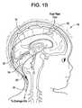
- FIG. 1Bis a partial sectional view showing a first catheter draining fluid from a fluid filled cyst, and a second catheter draining fluid from the lateral ventricle;
- FIG. 2Ashows a plan view of a branched drainage conduit, with each conduit having a one-way valve that opens with a predetermined opening pressure that is greater than zero;
- FIG. 2Bshows a plan view of a branched drainage conduit, with each conduit having a one-way valve that opens with approximately zero opening pressure;
- FIG. 2Cshows a plan view of a branched drainage conduit, with one conduit having a one-way valve that opens with a predetermined opening pressure that is greater than zero and the other conduit having a one-way valve that opens with approximately zero opening pressure.
- FIGS. 1A-2Ca shunt system 10 in accordance with the present invention is illustrated.
- a first catheter 12having a proximal end and a distal end.
- the first catheterhas at least one opening adjacent to its distal end, as is known in the art.
- a second catheter 14has a proximal end and a distal end.
- the second catheteralso has at least one opening adjacent to its distal end.
- a drainage catheter 16has a proximal end and a distal end. The proximal end of the drainage catheter 16 is in fluid communication with the proximal end of the first catheter and the proximal end of the second catheter.
- a first one-way valve 18is disposed in fluid communication with the first catheter 12 between its proximal end and its at least one opening.
- the first one-way valvepermits fluid flow within the first catheter 12 from the at least one opening to the proximal end with approximately zero opening pressure.
- the first one-way valvealso effectively blocks fluid flow within the first catheter 12 from the proximal end to the at least one opening.
- a second one-way valve 20is disposed in fluid communication with the second catheter 14 between the proximal end and the at least one opening.
- the second one-way valve 20permits fluid flow within the second catheter 14 from the at least one opening to the proximal end with a predetermined opening pressure that is greater than zero.
- the second one-way valvealso effectively blocks fluid flow within the second catheter 14 from the proximal end to the at least one opening.
- the first one-way valve 18 and the second one-way valve 20can be, for example, ball and cone valves or diaphragm valves.
- the second one-way valve 20is preferably an adjustable valve so that the threshold or opening pressure that allows fluid flow through a shunt system may vary.
- the predetermined opening pressure of the second one-way valve 20can be adjusted non-invasively with means such as a wireless communications (e.g., magnetically) or a wireless telemetric communication, which includes the transfer of data or other information.
- the predetermined opening pressure of the second one-way valve 20is preferably programmable in the range from approximately 10 mm H 2 O to approximately 400 mm H 2 O, and more preferably from approximately 10 mm H 2 O to approximately 200 mm H 2 O.
- Connector 22 , 22 ′, 22 ′′that may be used to facilitate fluid handling is illustrated.
- Connector 22 , 22 ′, 22 ′′has a first port 24 , 24 ′, 24 ′′, a second port 26 , 26 ′, 26 ′′ and a third port 28 , 28 ′, 28 ′′.
- the first portis in fluid communication with the proximal end of the first catheter.
- the second portis in fluid communication with the proximal end of the second catheter, and the third port is in fluid communication with the proximal end of the drainage catheter.
- the distal end of the drainage catheteris typically placed in the peritoneum. But the fluid could be drained elsewhere in the body, or the system could be used to drain fluid externally from the body.
- a first one-way valveis placed in fluid communication with the first catheter between its proximal end and the at least one opening such that the first one-way valve permits fluid flow from the at least one opening to the proximal end with a predetermined opening pressure that is greater than zero.
- the first one-way valveeffectively blocks fluid flow from the proximal end to the at least one opening.
- a second one-way valveis placed in fluid communication with the second catheter between the proximal end and the at least one opening such that the second one-way valve permits fluid flow from the at least one opening to the proximal end with approximately zero opening pressure.
- the second one-way valveeffectively blocks fluid flow from the proximal end to the at least one opening.
- the distal end of the first cathetercan be placed, for example, in the lateral ventricle, and the distal end of the second catheter can be placed in the fourth ventricle.
- the distal end of the first cathetercan be placed, for example, in fluid communication with a fluid filled cyst 30 , and the distal end of the second catheter can be placed in the fourth ventricle.
- the two one-way valvescould both open with approximately zero opening pressure as shown in FIG. 2B .
- the two one-way valvescould both open with a predetermined opening pressure that is greater than zero as shown in FIG. 2A .
Landscapes
- Health & Medical Sciences (AREA)
- Engineering & Computer Science (AREA)
- Biomedical Technology (AREA)
- Neurology (AREA)
- Ophthalmology & Optometry (AREA)
- Otolaryngology (AREA)
- Anesthesiology (AREA)
- Heart & Thoracic Surgery (AREA)
- Hematology (AREA)
- Life Sciences & Earth Sciences (AREA)
- Animal Behavior & Ethology (AREA)
- General Health & Medical Sciences (AREA)
- Public Health (AREA)
- Veterinary Medicine (AREA)
- External Artificial Organs (AREA)
Abstract
Description
- Not applicable.
- Not Applicable.
- The present invention relates to a multi-branched anti-reflux valve. More specifically, the present invention relates to a system and method for draining fluid from multiple drainage sites within the human brain.
- Hydrocephalus is most often treated by surgically inserting a shunt. The shunt diverts the flow of cerebrospinal fluid (“CSF”) from the ventricles of the brain to another area of the body where the CSF can be absorbed as part of the circulatory system. A shunt typically includes a ventricular catheter that is introduced through a burr hole in the skull and implanted in the patient's ventricle. A drainage catheter delivers the CSF to its ultimate drainage site (e.g., the peritoneum). Optionally, a valve may be used to regulate the one-way flow of CSF from the patient's ventricle to the drainage site.
- To drain fluid from more than one site, a surgeon has used multiple shunts. That is, a first shunt, having its own ventricular catheter and drainage catheter, is used to drain CSF from a first site, and a second shunt, having its own ventricular catheter and drainage catheter, is used to drain CSF from a second site.
- Occasionally the surgeon may have the need to drain fluid from multiple sites within the brain. If the surgeon were to modify the valve construct to drain from multiple sites with a simple Y-connector, cross draining may occur between the two sites within the brain as the CSF will travel along the path of least resistance. Thus, there is the need to provide surgeons with a device that will permit fluid to drain from multiple sites without cross draining occurring.
- The present invention provides these and other needs with a shunt system that includes a first catheter having a proximal end and a distal end. The first catheter has at least one opening adjacent to its distal end. A second catheter has a proximal end and a distal end. The second catheter has at least one opening adjacent to its distal end. A drainage catheter has a proximal end and a distal end. The proximal end of the drainage catheter is in fluid communication with the proximal end of the first catheter and the proximal end of the second catheter. A first one-way valve is disposed in fluid communication with the first catheter between its proximal end and its at least one opening. The first one-way valve permits fluid flow from the at least one opening to the proximal end with approximately zero opening pressure. The first one-way valve effectively blocks fluid flow from the proximal end to the at least one opening. A second one-way valve is disposed in fluid communication with the second catheter between its proximal end and its at least one opening. The second one-way valve permits fluid flow from the at least one opening to the proximal end with approximately zero opening pressure. The second one-way valve effectively blocks fluid flow from the proximal end to the at least one opening. Depending upon the needs of the surgeon however, the two one-way valves could both open with approximately zero opening pressure, or the two one-way valves could both open with a predetermined opening pressure that is greater than zero.
- The invention can be more fully understood from the following detailed description taken in conjunction with the accompanying drawings, in which:
FIG. 1A is a partial sectional view showing a first catheter draining fluid from the lateral ventricle of the human brain, and a second catheter draining fluid from the fourth ventricle of a human brain;FIG. 1B is a partial sectional view showing a first catheter draining fluid from a fluid filled cyst, and a second catheter draining fluid from the lateral ventricle;FIG. 2A shows a plan view of a branched drainage conduit, with each conduit having a one-way valve that opens with a predetermined opening pressure that is greater than zero;FIG. 2B shows a plan view of a branched drainage conduit, with each conduit having a one-way valve that opens with approximately zero opening pressure; andFIG. 2C shows a plan view of a branched drainage conduit, with one conduit having a one-way valve that opens with a predetermined opening pressure that is greater than zero and the other conduit having a one-way valve that opens with approximately zero opening pressure.- Referring now to
FIGS. 1A-2C , ashunt system 10 in accordance with the present invention is illustrated. Referring now toFIG. 1A , afirst catheter 12 having a proximal end and a distal end. The first catheter has at least one opening adjacent to its distal end, as is known in the art. Asecond catheter 14 has a proximal end and a distal end. The second catheter also has at least one opening adjacent to its distal end. Adrainage catheter 16 has a proximal end and a distal end. The proximal end of thedrainage catheter 16 is in fluid communication with the proximal end of the first catheter and the proximal end of the second catheter. A first one-way valve 18 is disposed in fluid communication with thefirst catheter 12 between its proximal end and its at least one opening. The first one-way valve permits fluid flow within thefirst catheter 12 from the at least one opening to the proximal end with approximately zero opening pressure. The first one-way valve also effectively blocks fluid flow within thefirst catheter 12 from the proximal end to the at least one opening. - A second one-
way valve 20 is disposed in fluid communication with thesecond catheter 14 between the proximal end and the at least one opening. The second one-way valve 20 permits fluid flow within thesecond catheter 14 from the at least one opening to the proximal end with a predetermined opening pressure that is greater than zero. The second one-way valve also effectively blocks fluid flow within thesecond catheter 14 from the proximal end to the at least one opening. The first one-way valve 18 and the second one-way valve 20 can be, for example, ball and cone valves or diaphragm valves. The second one-way valve 20 is preferably an adjustable valve so that the threshold or opening pressure that allows fluid flow through a shunt system may vary. U.S. Pat. Nos. 4,595,390, 4,615,691, 4,772,257, and 5,928,182 are exemplary typed of adjustable shunt valves, and the disclosures of which are all hereby incorporated by reference in their entirety. The predetermined opening pressure of the second one-way valve 20 can be adjusted non-invasively with means such as a wireless communications (e.g., magnetically) or a wireless telemetric communication, which includes the transfer of data or other information. The predetermined opening pressure of the second one-way valve 20 is preferably programmable in the range from approximately 10 mm H2O to approximately 400 mm H2O, and more preferably from approximately 10 mm H2O to approximately 200 mm H2O. - Referring now to
FIGS. 2A-2C , aconnector Connector first port second port third port - To use the
shunt system 10 to drain cerebral spinal fluid (CSF) from multiple sites within the brain the surgeon will place the proximal end of the drainage catheter in fluid communication with the proximal end of the first catheter and the proximal end of the second catheter. A first one-way valve is placed in fluid communication with the first catheter between its proximal end and the at least one opening such that the first one-way valve permits fluid flow from the at least one opening to the proximal end with a predetermined opening pressure that is greater than zero. The first one-way valve effectively blocks fluid flow from the proximal end to the at least one opening. A second one-way valve is placed in fluid communication with the second catheter between the proximal end and the at least one opening such that the second one-way valve permits fluid flow from the at least one opening to the proximal end with approximately zero opening pressure. The second one-way valve effectively blocks fluid flow from the proximal end to the at least one opening. - As illustrated in
FIG. 1A , the distal end of the first catheter can be placed, for example, in the lateral ventricle, and the distal end of the second catheter can be placed in the fourth ventricle. Alternatively, as illustrated inFIG. 1B , the distal end of the first catheter can be placed, for example, in fluid communication with a fluid filledcyst 30, and the distal end of the second catheter can be placed in the fourth ventricle. - Of course, however, depending upon the needs of the surgeon, the two one-way valves could both open with approximately zero opening pressure as shown in
FIG. 2B . Likewise, the two one-way valves could both open with a predetermined opening pressure that is greater than zero as shown inFIG. 2A . - It will be understood that the foregoing is only illustrative of the principles of the invention, and that various modifications can be made by those skilled in the art without departing from the scope and spirit of the invention. All references cited herein are expressly incorporated by reference in their entirety.
- One skilled in the art will appreciate further features and advantages of the invention based on the above-described embodiments. While there have been shown, described, and pointed out fundamental novel features of the invention as applied to a preferred embodiment thereof, it will be understood that various omissions, substitutions, and changes in the form and details of the devices illustrated, and in their operation, may be made by those skilled in the art without departing from the spirit and scope of the invention. For example, it is expressly intended that all combinations of those elements and/or steps, which perform substantially the same function, in substantially the same way, to achieve the same results are within the scope of the invention. Substitutions of elements from one described embodiment to another are also fully intended and contemplated. It is also to be understood that the drawings are not necessarily drawn to scale, but that they are merely conceptual in nature. Accordingly, the invention is not to be limited by what has been particularly shown and described, except as indicated by the appended claims. All publications and references cited herein are expressly incorporated herein by reference in their entirety.
Claims (21)
Priority Applications (2)
| Application Number | Priority Date | Filing Date | Title |
|---|---|---|---|
| US11/212,412US20070078398A1 (en) | 2005-08-27 | 2005-08-27 | Multi-branched anti-reflux valve |
| US12/772,847US9220877B2 (en) | 2005-08-27 | 2010-05-03 | Multi-branched anti-reflux valve |
Applications Claiming Priority (1)
| Application Number | Priority Date | Filing Date | Title |
|---|---|---|---|
| US11/212,412US20070078398A1 (en) | 2005-08-27 | 2005-08-27 | Multi-branched anti-reflux valve |
Related Child Applications (1)
| Application Number | Title | Priority Date | Filing Date |
|---|---|---|---|
| US12/772,847DivisionUS9220877B2 (en) | 2005-08-27 | 2010-05-03 | Multi-branched anti-reflux valve |
Publications (1)
| Publication Number | Publication Date |
|---|---|
| US20070078398A1true US20070078398A1 (en) | 2007-04-05 |
Family
ID=37902785
Family Applications (2)
| Application Number | Title | Priority Date | Filing Date |
|---|---|---|---|
| US11/212,412AbandonedUS20070078398A1 (en) | 2005-08-27 | 2005-08-27 | Multi-branched anti-reflux valve |
| US12/772,847Active2028-04-04US9220877B2 (en) | 2005-08-27 | 2010-05-03 | Multi-branched anti-reflux valve |
Family Applications After (1)
| Application Number | Title | Priority Date | Filing Date |
|---|---|---|---|
| US12/772,847Active2028-04-04US9220877B2 (en) | 2005-08-27 | 2010-05-03 | Multi-branched anti-reflux valve |
Country Status (1)
| Country | Link |
|---|---|
| US (2) | US20070078398A1 (en) |
Cited By (3)
| Publication number | Priority date | Publication date | Assignee | Title |
|---|---|---|---|---|
| WO2010000461A1 (en)* | 2008-07-02 | 2010-01-07 | C.Miethke Gmbh & Co Kg | Cerebrospinal fluid drainage |
| US20120232462A1 (en)* | 2009-12-23 | 2012-09-13 | Christoph Miethke | Implantable hydrocephalus shunt system |
| US20140276347A1 (en)* | 2013-03-15 | 2014-09-18 | University Of Rochester | Intraosseous shunts |
Families Citing this family (1)
| Publication number | Priority date | Publication date | Assignee | Title |
|---|---|---|---|---|
| CN110496299A (en)* | 2019-08-14 | 2019-11-26 | 福建医科大学附属第一医院 | A double-lumen catheter for continuous purification of cerebrospinal fluid |
Citations (34)
| Publication number | Priority date | Publication date | Assignee | Title |
|---|---|---|---|---|
| US686647A (en)* | 1901-07-05 | 1901-11-12 | William H Booth | Fishing-rod. |
| US2866457A (en)* | 1956-12-20 | 1958-12-30 | Cutter Lab | Apparatus for administration of parenteral fluids |
| US4072153A (en)* | 1976-03-03 | 1978-02-07 | Swartz William H | Post hysterectomy fluid drainage tube |
| US4432853A (en)* | 1981-06-10 | 1984-02-21 | The United States Of America As Represented By The Administrator Of The National Aeronautics And Space Administration | Method of making an ion beam sputter-etched ventricular catheter for hydrocephalus shunt |
| US4681559A (en)* | 1985-12-23 | 1987-07-21 | Cordis Corporation | Plural valve three stage pressure relief system |
| US4712551A (en)* | 1986-10-14 | 1987-12-15 | Rayhanabad Simon B | Vascular shunt |
| US4979937A (en)* | 1987-12-22 | 1990-12-25 | Khorasani Ahmad R | Method and apparatus involving intercostal and lumbar perfusion |
| US5171415A (en)* | 1990-12-21 | 1992-12-15 | Novellus Systems, Inc. | Cooling method and apparatus for magnetron sputtering |
| US5333726A (en)* | 1993-01-15 | 1994-08-02 | Regents Of The University Of California | Magnetron sputtering source |
| US5575767A (en)* | 1994-09-16 | 1996-11-19 | Stevens; Robert C. | Method and apparatus for high pressure one-way fluid valving in angiography |
| US5747119A (en)* | 1993-02-05 | 1998-05-05 | Kabushiki Kaisha Toshiba | Vapor deposition method and apparatus |
| US5755773A (en)* | 1996-06-04 | 1998-05-26 | Medtronic, Inc. | Endoluminal prosthetic bifurcation shunt |
| US5755938A (en)* | 1993-08-24 | 1998-05-26 | Alps Electric Co., Ltd. | Single chamber for CVD and sputtering film manufacturing |
| US5906641A (en)* | 1997-05-27 | 1999-05-25 | Schneider (Usa) Inc | Bifurcated stent graft |
| US5953827A (en)* | 1997-11-05 | 1999-09-21 | Applied Materials, Inc. | Magnetron with cooling system for process chamber of processing system |
| US5985115A (en)* | 1997-04-11 | 1999-11-16 | Novellus Systems, Inc. | Internally cooled target assembly for magnetron sputtering |
| US6080287A (en)* | 1998-05-06 | 2000-06-27 | Tokyo Electron Limited | Method and apparatus for ionized physical vapor deposition |
| US6086553A (en)* | 1999-07-01 | 2000-07-11 | Akbik; Mohamad J. | Arteriovenous shunt |
| US6113752A (en)* | 1998-07-07 | 2000-09-05 | Techno-Coat Oberflachentechnik Gmbh | Method and device for coating substrate |
| US6207026B1 (en)* | 1999-10-13 | 2001-03-27 | Applied Materials, Inc. | Magnetron with cooling system for substrate processing system |
| US6221217B1 (en)* | 1995-07-10 | 2001-04-24 | Cvc, Inc. | Physical vapor deposition system having reduced thickness backing plate |
| US6235634B1 (en)* | 1997-10-08 | 2001-05-22 | Applied Komatsu Technology, Inc. | Modular substrate processing system |
| US6238532B1 (en)* | 1999-10-29 | 2001-05-29 | International Business Machines Corporation | Radio-frequency coil for use in an ionized physical vapor deposition apparatus |
| US6413380B1 (en)* | 2000-08-14 | 2002-07-02 | International Business Machines Corporation | Method and apparatus for providing deposited layer structures and articles so produced |
| US6454920B1 (en)* | 1997-12-17 | 2002-09-24 | Unaxis Trading Ag | Magnetron sputtering source |
| US6554790B1 (en)* | 1998-11-20 | 2003-04-29 | Intuitive Surgical, Inc. | Cardiopulmonary bypass device and method |
| US6641701B1 (en)* | 2000-06-14 | 2003-11-04 | Applied Materials, Inc. | Cooling system for magnetron sputtering apparatus |
| US6689085B1 (en)* | 1996-07-11 | 2004-02-10 | Eunoe, Inc. | Method and apparatus for treating adult-onset dementia of the Alzheimer's type |
| US6692618B2 (en)* | 2001-05-03 | 2004-02-17 | Unaxis Balzers Limited | Magnetron sputter source with multipart target |
| US6730194B2 (en)* | 1997-11-05 | 2004-05-04 | Unaxis Balzers Aktiengesellschaft | Method for manufacturing disk-shaped workpieces with a sputter station |
| US6740585B2 (en)* | 2001-07-25 | 2004-05-25 | Applied Materials, Inc. | Barrier formation using novel sputter deposition method with PVD, CVD, or ALD |
| US6758948B2 (en)* | 2000-02-25 | 2004-07-06 | Tokyo Electron Limited | Method and apparatus for depositing films |
| US6817985B2 (en)* | 1999-03-31 | 2004-11-16 | Coaxia, Inc. | Intravascular spinal perfusion and cooling for use during aortic surgery |
| US6859953B1 (en)* | 2002-09-13 | 2005-03-01 | Steven E. Christensen | Jet propulsion system for spa or jetted bath using control of air draw to Venturi jets with a three-way air control valve |
Family Cites Families (6)
| Publication number | Priority date | Publication date | Assignee | Title |
|---|---|---|---|---|
| US4615691A (en) | 1983-12-08 | 1986-10-07 | Salomon Hakim | Surgically-implantable stepping motor |
| US4595390A (en) | 1983-07-21 | 1986-06-17 | Salomon Hakim | Magnetically-adjustable cerebrospinal fluid shunt valve |
| US4772257A (en) | 1983-12-08 | 1988-09-20 | Salomon Hakim | External programmer for magnetically-adjustable cerebrospinal fluid shunt valve |
| US5928182A (en) | 1997-07-02 | 1999-07-27 | Johnson & Johnson Professional, Inc. | Pediatric programmable hydrocephalus valve |
| US6530894B1 (en) | 1999-11-16 | 2003-03-11 | Coaxia, Inc. | Aortic shunt with spinal perfusion and cooling device |
| US6913589B2 (en)* | 2002-01-14 | 2005-07-05 | Codman & Shurtleff, Inc. | Multi-catheter insertion device and method |
- 2005
- 2005-08-27USUS11/212,412patent/US20070078398A1/ennot_activeAbandoned
- 2010
- 2010-05-03USUS12/772,847patent/US9220877B2/enactiveActive
Patent Citations (34)
| Publication number | Priority date | Publication date | Assignee | Title |
|---|---|---|---|---|
| US686647A (en)* | 1901-07-05 | 1901-11-12 | William H Booth | Fishing-rod. |
| US2866457A (en)* | 1956-12-20 | 1958-12-30 | Cutter Lab | Apparatus for administration of parenteral fluids |
| US4072153A (en)* | 1976-03-03 | 1978-02-07 | Swartz William H | Post hysterectomy fluid drainage tube |
| US4432853A (en)* | 1981-06-10 | 1984-02-21 | The United States Of America As Represented By The Administrator Of The National Aeronautics And Space Administration | Method of making an ion beam sputter-etched ventricular catheter for hydrocephalus shunt |
| US4681559A (en)* | 1985-12-23 | 1987-07-21 | Cordis Corporation | Plural valve three stage pressure relief system |
| US4712551A (en)* | 1986-10-14 | 1987-12-15 | Rayhanabad Simon B | Vascular shunt |
| US4979937A (en)* | 1987-12-22 | 1990-12-25 | Khorasani Ahmad R | Method and apparatus involving intercostal and lumbar perfusion |
| US5171415A (en)* | 1990-12-21 | 1992-12-15 | Novellus Systems, Inc. | Cooling method and apparatus for magnetron sputtering |
| US5333726A (en)* | 1993-01-15 | 1994-08-02 | Regents Of The University Of California | Magnetron sputtering source |
| US5747119A (en)* | 1993-02-05 | 1998-05-05 | Kabushiki Kaisha Toshiba | Vapor deposition method and apparatus |
| US5755938A (en)* | 1993-08-24 | 1998-05-26 | Alps Electric Co., Ltd. | Single chamber for CVD and sputtering film manufacturing |
| US5575767A (en)* | 1994-09-16 | 1996-11-19 | Stevens; Robert C. | Method and apparatus for high pressure one-way fluid valving in angiography |
| US6221217B1 (en)* | 1995-07-10 | 2001-04-24 | Cvc, Inc. | Physical vapor deposition system having reduced thickness backing plate |
| US5755773A (en)* | 1996-06-04 | 1998-05-26 | Medtronic, Inc. | Endoluminal prosthetic bifurcation shunt |
| US6689085B1 (en)* | 1996-07-11 | 2004-02-10 | Eunoe, Inc. | Method and apparatus for treating adult-onset dementia of the Alzheimer's type |
| US5985115A (en)* | 1997-04-11 | 1999-11-16 | Novellus Systems, Inc. | Internally cooled target assembly for magnetron sputtering |
| US5906641A (en)* | 1997-05-27 | 1999-05-25 | Schneider (Usa) Inc | Bifurcated stent graft |
| US6235634B1 (en)* | 1997-10-08 | 2001-05-22 | Applied Komatsu Technology, Inc. | Modular substrate processing system |
| US5953827A (en)* | 1997-11-05 | 1999-09-21 | Applied Materials, Inc. | Magnetron with cooling system for process chamber of processing system |
| US6730194B2 (en)* | 1997-11-05 | 2004-05-04 | Unaxis Balzers Aktiengesellschaft | Method for manufacturing disk-shaped workpieces with a sputter station |
| US6454920B1 (en)* | 1997-12-17 | 2002-09-24 | Unaxis Trading Ag | Magnetron sputtering source |
| US6080287A (en)* | 1998-05-06 | 2000-06-27 | Tokyo Electron Limited | Method and apparatus for ionized physical vapor deposition |
| US6113752A (en)* | 1998-07-07 | 2000-09-05 | Techno-Coat Oberflachentechnik Gmbh | Method and device for coating substrate |
| US6554790B1 (en)* | 1998-11-20 | 2003-04-29 | Intuitive Surgical, Inc. | Cardiopulmonary bypass device and method |
| US6817985B2 (en)* | 1999-03-31 | 2004-11-16 | Coaxia, Inc. | Intravascular spinal perfusion and cooling for use during aortic surgery |
| US6086553A (en)* | 1999-07-01 | 2000-07-11 | Akbik; Mohamad J. | Arteriovenous shunt |
| US6207026B1 (en)* | 1999-10-13 | 2001-03-27 | Applied Materials, Inc. | Magnetron with cooling system for substrate processing system |
| US6238532B1 (en)* | 1999-10-29 | 2001-05-29 | International Business Machines Corporation | Radio-frequency coil for use in an ionized physical vapor deposition apparatus |
| US6758948B2 (en)* | 2000-02-25 | 2004-07-06 | Tokyo Electron Limited | Method and apparatus for depositing films |
| US6641701B1 (en)* | 2000-06-14 | 2003-11-04 | Applied Materials, Inc. | Cooling system for magnetron sputtering apparatus |
| US6413380B1 (en)* | 2000-08-14 | 2002-07-02 | International Business Machines Corporation | Method and apparatus for providing deposited layer structures and articles so produced |
| US6692618B2 (en)* | 2001-05-03 | 2004-02-17 | Unaxis Balzers Limited | Magnetron sputter source with multipart target |
| US6740585B2 (en)* | 2001-07-25 | 2004-05-25 | Applied Materials, Inc. | Barrier formation using novel sputter deposition method with PVD, CVD, or ALD |
| US6859953B1 (en)* | 2002-09-13 | 2005-03-01 | Steven E. Christensen | Jet propulsion system for spa or jetted bath using control of air draw to Venturi jets with a three-way air control valve |
Cited By (6)
| Publication number | Priority date | Publication date | Assignee | Title |
|---|---|---|---|---|
| WO2010000461A1 (en)* | 2008-07-02 | 2010-01-07 | C.Miethke Gmbh & Co Kg | Cerebrospinal fluid drainage |
| US20110166495A1 (en)* | 2008-07-02 | 2011-07-07 | Christoph Miethke | Cerebrospinal fluid drainage |
| US9295821B2 (en) | 2008-07-02 | 2016-03-29 | Christoph Miethke | Cerebrospinal fluid drainage |
| US20120232462A1 (en)* | 2009-12-23 | 2012-09-13 | Christoph Miethke | Implantable hydrocephalus shunt system |
| US8870809B2 (en)* | 2009-12-23 | 2014-10-28 | Christoph Miethke Gmbh & Co Kg | Implantable hydrocephalus shunt system |
| US20140276347A1 (en)* | 2013-03-15 | 2014-09-18 | University Of Rochester | Intraosseous shunts |
Also Published As
| Publication number | Publication date |
|---|---|
| US9220877B2 (en) | 2015-12-29 |
| US20100210992A1 (en) | 2010-08-19 |
Similar Documents
| Publication | Publication Date | Title |
|---|---|---|
| US7699800B2 (en) | Multi-catheter insertion device and method | |
| CA2477054C (en) | Vesicular shunt for the drainage of excess fluid | |
| JP4309649B2 (en) | Cerebrospinal fluid shunt device and hydrocephalus treatment method | |
| CA2462367C (en) | Hydrocephalus shunt system with endoscopic placement features | |
| JP4597610B2 (en) | Cutable detection catheter | |
| ES2305667T3 (en) | NEEDLE PROTECTOR WITH INHERENT CHARACTERISTICS TO DIRECT A PROBE. | |
| US9220877B2 (en) | Multi-branched anti-reflux valve | |
| US20040236309A1 (en) | Mesh ventricular catheter with antithrombogenic coating | |
| US20050085763A1 (en) | Adjustable resistance valve for a cerebrospinal fluid shunt system | |
| Børgesen et al. | Shunting to the cranial venous sinus using the SinuShunt | |
| Lee et al. | Pseudotumor cerebri patients with shunts from the cisterna magna: clinical course and telemetric intracranial pressure data | |
| Oliveira et al. | Updating technology of shunt valves | |
| US20170189655A1 (en) | System and method for draining cerebrospinal fluid | |
| US12171966B2 (en) | Cerebral spinal fluid shunt plug |
Legal Events
| Date | Code | Title | Description |
|---|---|---|---|
| AS | Assignment | Owner name:CODMAN & SHURTLEFF, MASSACHUSETTS Free format text:ASSIGNMENT OF ASSIGNORS INTEREST;ASSIGNORS:DEXTRADEUR, ALAN J.;KRAUS, ROBERT;REEL/FRAME:016935/0609 Effective date:20050824 | |
| STCB | Information on status: application discontinuation | Free format text:ABANDONED -- FAILURE TO RESPOND TO AN OFFICE ACTION | |
| AS | Assignment | Owner name:DEPUY SPINE, LLC, MASSACHUSETTS Free format text:ASSIGNMENT OF ASSIGNORS INTEREST;ASSIGNOR:CODMAN & SHURTLEFF, INC.;REEL/FRAME:036704/0245 Effective date:20121230 Owner name:HAND INNOVATIONS LLC, FLORIDA Free format text:ASSIGNMENT OF ASSIGNORS INTEREST;ASSIGNOR:DEPUY SPINE, LLC;REEL/FRAME:036704/0304 Effective date:20121230 Owner name:DEPUY SYNTHES PRODUCTS, INC., MASSACHUSETTS Free format text:CHANGE OF NAME;ASSIGNOR:DEPUY SYNTHES PRODUCTS, LLC;REEL/FRAME:036741/0961 Effective date:20141219 Owner name:DEPUY SYNTHES PRODUCTS, LLC, MASSACHUSETTS Free format text:CHANGE OF NAME;ASSIGNOR:HAND INNOVATIONS LLC;REEL/FRAME:036741/0958 Effective date:20121231 |