US20070019445A1 - Switch with fully isolated power sourcing equipment control - Google Patents
Switch with fully isolated power sourcing equipment controlDownload PDFInfo
- Publication number
- US20070019445A1 US20070019445A1US11/369,057US36905706AUS2007019445A1US 20070019445 A1US20070019445 A1US 20070019445A1US 36905706 AUS36905706 AUS 36905706AUS 2007019445 A1US2007019445 A1US 2007019445A1
- Authority
- US
- United States
- Prior art keywords
- power
- cable
- signal
- power signal
- isolated
- Prior art date
- Legal status (The legal status is an assumption and is not a legal conclusion. Google has not performed a legal analysis and makes no representation as to the accuracy of the status listed.)
- Granted
Links
- 238000012358sourcingMethods0.000titledescription3
- 230000003750conditioning effectEffects0.000claimsabstractdescription54
- 238000001514detection methodMethods0.000claimsabstractdescription53
- 238000002955isolationMethods0.000claimsabstractdescription38
- 238000000034methodMethods0.000claimsabstractdescription16
- 230000008569processEffects0.000claimsabstractdescription12
- 238000012545processingMethods0.000claimsdescription6
- 238000001914filtrationMethods0.000claimsdescription5
- 238000010586diagramMethods0.000description23
- 230000003287optical effectEffects0.000description8
- 238000004891communicationMethods0.000description7
- 238000004804windingMethods0.000description5
- 230000005012migrationEffects0.000description4
- 238000013508migrationMethods0.000description4
- 238000005516engineering processMethods0.000description3
- 230000003278mimic effectEffects0.000description3
- 230000008901benefitEffects0.000description2
- 239000003990capacitorSubstances0.000description2
- 230000001143conditioned effectEffects0.000description2
- 230000001419dependent effectEffects0.000description1
- 230000036541healthEffects0.000description1
- 230000010354integrationEffects0.000description1
- 239000000463materialSubstances0.000description1
- 238000001208nuclear magnetic resonance pulse sequenceMethods0.000description1
- 230000003071parasitic effectEffects0.000description1
- 238000012163sequencing techniqueMethods0.000description1
- 238000012360testing methodMethods0.000description1
Images


Classifications
- H—ELECTRICITY
- H02—GENERATION; CONVERSION OR DISTRIBUTION OF ELECTRIC POWER
- H02M—APPARATUS FOR CONVERSION BETWEEN AC AND AC, BETWEEN AC AND DC, OR BETWEEN DC AND DC, AND FOR USE WITH MAINS OR SIMILAR POWER SUPPLY SYSTEMS; CONVERSION OF DC OR AC INPUT POWER INTO SURGE OUTPUT POWER; CONTROL OR REGULATION THEREOF
- H02M3/00—Conversion of DC power input into DC power output
- H02M3/22—Conversion of DC power input into DC power output with intermediate conversion into AC
- H02M3/24—Conversion of DC power input into DC power output with intermediate conversion into AC by static converters
- H02M3/28—Conversion of DC power input into DC power output with intermediate conversion into AC by static converters using discharge tubes with control electrode or semiconductor devices with control electrode to produce the intermediate AC
- H02M3/325—Conversion of DC power input into DC power output with intermediate conversion into AC by static converters using discharge tubes with control electrode or semiconductor devices with control electrode to produce the intermediate AC using devices of a triode or a transistor type requiring continuous application of a control signal
- H02M3/335—Conversion of DC power input into DC power output with intermediate conversion into AC by static converters using discharge tubes with control electrode or semiconductor devices with control electrode to produce the intermediate AC using devices of a triode or a transistor type requiring continuous application of a control signal using semiconductor devices only
- H02M3/33507—Conversion of DC power input into DC power output with intermediate conversion into AC by static converters using discharge tubes with control electrode or semiconductor devices with control electrode to produce the intermediate AC using devices of a triode or a transistor type requiring continuous application of a control signal using semiconductor devices only with automatic control of the output voltage or current, e.g. flyback converters
- H02M3/33523—Conversion of DC power input into DC power output with intermediate conversion into AC by static converters using discharge tubes with control electrode or semiconductor devices with control electrode to produce the intermediate AC using devices of a triode or a transistor type requiring continuous application of a control signal using semiconductor devices only with automatic control of the output voltage or current, e.g. flyback converters with galvanic isolation between input and output of both the power stage and the feedback loop
Definitions
- the present inventionrelates to electronics, and, in particular, to Power Sourcing Equipment (PSE) for communication systems conforming to the IEEE 802.3 Ethernet and IEEE 802.3af Power over Ethernet (PoE) standards.
- PSEPower Sourcing Equipment
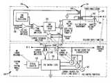
- FIG. 1shows a block diagram of a portion of a conventional Ethernet switch 100 for a communication system that conforms to both the IEEE 802.3 Ethernet standard and the IEEE 802.3af PoE standard, the teachings of both of which are incorporated herein by reference.
- Ethernet switch 100comprises Ethernet Physical-Layer (PHY) module 102 , RJ-45 Ethernet connector 104 , 48-volt switcher 106 , line-side PSE control and power conditioning module 108 , isolated-side PSE control module 110 , four-pair signal-isolation transformer 112 , power-isolation transformer 114 , and optical isolator 116 .
- PHYEthernet Physical-Layer
- Ethernet PHY module 102communicates with a Media Access Controller (MAC) and switching function and processes incoming and outgoing differential data signals that are transmitted over an Ethernet cable (not shown) that is connected to switch 100 at Ethernet connector 104 .
- switch 100is a PSE-capable switch that can provide a 48-volt DC (cable power) signal on the Ethernet cable to power a so-called powered device (PD), such as an Internet Protocol (IP) telephone, such that the PD device does not require any additional power source to operate.
- PDpowered device
- IPInternet Protocol
- the 48-volt DC signalis provided by switcher 106 and modules 108 and 110 .
- Transformers 112 and 114 and optical isolator 116provide high-voltage electrical isolation between (1) circuitry, such as Ethernet PHY module 102 , switcher 106 , and PSE control module 110 , located on the so-called isolated side of switch 100 (i.e., the primary side of the transformers) and (2) circuitry, such as Ethernet connector 104 and PSE control and power conditioning module 108 , located on the so-called line side of switch 100 (i.e., the transformers' secondary side), to protect the isolated-side circuitry from high voltages that might appear on the line side, such as those that can occur when lightening strikes near an Ethernet cable connected to connector 104 .
- circuitrysuch as Ethernet PHY module 102 , switcher 106 , and PSE control module 110
- circuitrysuch as Ethernet connector 104 and PSE control and power conditioning module 108
- Switcher 106provides an AC power signal that is converted by power-isolation transformer 114 into a transformed AC power signal that can be converted by line-side PSE control and power conditioning module 108 into the 48-volt (differential) DC signal that is applied to the center taps of the secondary-side coils of two of the four transformer pairs in signal-isolation transformer 112 .
- signal-isolation transformer 112has four pairs of transformer coils, where the 48-volt DC signal is applied to the center taps of two of the four secondary-side coils.
- the IEEE 802.3 Ethernet standardalso covers lower-rate (e.g., 10 Mbit and 100 Mbit) Ethernet systems that have only two pairs of coils, where two of the four wire pairs in the Ethernet cable are spares.
- the 48-volt DC signalcan be applied directed to the two spare wire pairs to power a PD device.
- line-side PSE control and power conditioning module 108provides two PSE control functions (i.e., detection and classification) and three PSE power conditioning functions (i.e., rectification, filtering, and impedance control).
- line-side PSE module 108sequentially applies two different, low-power signals to the transformer coils (either low-current or low-voltage depending on the implementation, such as a first low-power signal of approximately 3 volts followed by a second low-power signal of approximately 8 volts, instead of the full 48-volt DC signal) to enable line-side PSE module 108 to detect whether a valid PD device (which is required by the PoE standard to have a 25-Kohm impedance across the lines that provide the detection signal) is currently connected to Ethernet connector 104 via an Ethernet cable.
- two different, low-power signalsto the transformer coils (either low-current or low-voltage depending on the implementation, such as a first low-power signal of approximately 3 volts followed by a second low-power signal of approximately 8 volts, instead of the full 48-volt DC signal) to enable line-side PSE module 108 to detect whether a valid PD device (which is required by the PoE standard to have a 25-Kohm imped
- line-side PSE module 108(optionally) performs classification, during which line-side PSE module 108 increases the level of the applied signal to approximately 18 volts and measures the PD signature current draw to determine the power classification of the detected PD device.
- line-side PSE module 108performs power conditioning, during which line-side PSE module 108 generates and applies the appropriate 48-volt DC signal via connector 104 to the Ethernet cable to power the PD device.
- This power conditioning functioninvolves rectification and filtering of the transformed AC signal that is applied to line-side PSE module 108 from the secondary side of transformer 114 to generate the 48-volt DC signal.
- the power conditioning functionalso involves impedance control for the 48-volt DC signal. If no PD device is detected, then line-side PSE module 108 does not generate and apply a 48-volt DC signal to the Ethernet cable.
- switch 100may be configured to support multiple Ethernet ports, like the port associated with Ethernet connector 104 .
- line-side PSE control and power conditioning module 108is implemented as a relatively large integrated circuit (IC) that is capable of simultaneously supporting four different Ethernet ports. Examples of such line-side PSE control and power conditioning modules are:
- isolated-side PSE control module 110provides a certain (relatively limited) level of operating functionality.
- additional (e.g., switch-vendor value-added) functionsare provided by isolated-side PSE control module 110 , which is typically implemented using a microcontroller.
- isolated-side PSE control module 110is power balancing between multiple (e.g., as many as 48 or more) PD devices connected to a single Ethernet switch, where power balancing is based on the results of the PD power classification performed on each PD device.
- isolated-side PSE control module 110receives (explicit) information about the status of the operations at line-side PSE module 108 via optical isolator 116 and transmits control signals to control the operations at line-side PSE module 108 via optical isolator 116 .
- Such a conventional configuration for switch 100has a number of disadvantages. First of all, there is a considerable dollar cost to providing all of this circuitry associated with these functions. Furthermore, when two or more PD devices are connected to different Ethernet connectors supported by a single line-side PSE control and power conditioning module, there is no electrical isolation to protect the rest of the PD devices from a lightening strike near any one of the PD devices.
- the present inventionis an apparatus having an isolated side and a line side.
- the apparatuscomprises a physical-layer module, a power switcher, a power conditioning module, and a control module.
- the physical-layer moduleis (1) located on the isolated side of the apparatus, (2) adapted to be electrically coupled via a signal-isolation transformer to a cable connector located on the line side of the apparatus, and (3) adapted to process signals transmitted over the cable.
- the power switcheris located on the isolated side of the apparatus.
- the power conditioning moduleis (1) located on the line side of the apparatus, (2) electrically coupled to the power switcher via a power-isolation transformer adapted to convert an AC power signal received from the power switcher into a transformed AC power signal, and (3) adapted to convert the transformed AC power signal into a cable power signal to be supplied via the connector to the cable in order to power a cable-powered device connected to the cable.
- the control moduleis located on the isolated side of the apparatus and adapted to perform a detection function in which the control module determines whether or not a cable-powered device is connected to the cable.
- the present inventionis a method for powering a cable-powered device using an apparatus having a line side and an isolated side, wherein the cable-powered device is connected to the line-side of the apparatus via a cable.
- signals transmitted from the cable-powered device over the cableare received at the line side of the apparatus.
- the signals from the cable-powered deviceare (1) transmitted from the line side of the apparatus to the isolated side of the apparatus via a signal-isolation transformer located between the line side of the apparatus and the isolated side of the apparatus and (2) processed on the isolated side of the apparatus.
- An AC power signal on the isolated side of the apparatusis converted into a transformed AC power signal on the line side of the apparatus via a power-isolation transformer located between the line side of the apparatus and the isolated side of the apparatus.
- the transformed AC power signalis converted, on the line side of the apparatus, into a cable power signal, which is supplied to the cable in order to power the cable-powered device.
- a determinationis made, on the isolated side of the apparatus, that the cable-powered device is connected to the cable based on signals received at the isolated side of the apparatus from the line side of the apparatus via the power-isolation transformer.
- FIG. 1shows a block diagram of a portion of a conventional Ethernet switch for a communication system that conforms to both the IEEE 802.3 Ethernet standard and the IEEE 802.3af PoE standard;
- FIG. 2shows a block diagram of a portion of an Ethernet switch for a communication system that conforms to the IEEE 802.3 Ethernet and 802.3af PoE standards, according to one embodiment of the present invention
- FIG. 3shows a schematic block diagram of the switcher, the line-side PSE control and power conditioning module, the power-isolation transformer, and the optical isolator of the conventional Ethernet switch of FIG. 1 ;
- FIG. 4shows the schematic block diagram of FIG. 3 annotated to indicate the migration of functions associated with particular elements in the line-side circuitry of the PSE control and power conditioning module of FIG. 1 to a combined switcher/PSE control module corresponding to a combined implementation of the switcher and the isolated-side PSE control module of FIG. 2 ;
- FIG. 5shows a schematic block diagram of the switcher, the line-side PSE power conditioning module, the isolated-side PSE control module, and the power-isolation transformer of the Ethernet switch of FIG. 2 , according to one possible embodiment of the present invention
- FIG. 6shows a schematic block diagram of the switcher, the line-side PSE power conditioning module, the isolated-side PSE control module, and the power-isolation transformer of the Ethernet switch of FIG. 2 , according to one possible low-voltage, mixed-signal, CMOS-technology embodiment of the present invention
- FIG. 7shows a schematic block diagram of only those elements of FIG. 6 that are involved in the PSE detection mode of operation
- FIG. 8shows a schematic block diagram of only those elements of FIG. 6 that are involved in the PSE classification mode of operation.
- FIG. 9shows a schematic block diagram of only those elements of FIG. 6 that are involved in the PSE power-on mode of operation.
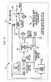
- FIG. 2shows a block diagram of a portion of an Ethernet switch 200 for a communication system that conforms to the IEEE 802.3 Ethernet and the IEEE 802.3af Power over Ethernet (PoE) standards, according to one embodiment of the present invention.
- Ethernet switch 200comprises Ethernet PHY module 202 , RJ-45 Ethernet connector 204 , 48-volt switcher 206 , line-side PSE power conditioning module 208 , isolated-side PSE control module 210 , four-pair signal-isolation transformer 212 , and power-isolation transformer 214 , where switcher 206 and power conditioning module 208 function together as an isolated switching power supply.
- Ethernet PHY module 202 , connector 204 , and transformers 212 and 214are similar to the corresponding elements in conventional switch 100 of FIG. 1 . Note that, unlike switch 100 of FIG. 1 , switch 200 does not have any optical isolator.
- the PSE detection and (optional) classification functions that were performed by line-side PSE control and power conditioning module 108 of FIG. 1 and all of the PSE control functions that were performed by isolated-side PSE control module 110 of FIG. 1are now performed by isolated-side PSE control module 210 of FIG. 2 .
- the only PSE functions that remain on the line side of switch 200 of FIG. 2are the power conditioning functions implemented by PSE power conditioning module 208 of FIG. 2 .
- These power conditioning functionsinclude, but are not limited to, rectification, filtering, and impedance control. Note that, in this embodiment, isolated-side PSE control module 210 does not receive any explicit information from the line side of switch 200 about the status of the operations at line-side PSE power conditioning module 208 .
- Ethernet PHY module 202 , switcher 206 , and PSE control module 210are preferably, but do not have to be, implemented in a combined manner on a single integrated circuit.
- a switch of the present inventioncan be configured with multiple Ethernet ports, while providing electrical isolation between all of the Ethernet ports.
- the high voltage associated with a lightening strike near an Ethernet cable connected to one of the Ethernet portswill not reach any of the other Ethernet ports (or their associated cables and PD devices).
- each portcan be designed to support multiple Ethernet ports, with each port having its own switcher (like switcher 206 ), transformer (like transformer 214 ), PSE power conditioning module (like module 208 ) and Ethernet connector (like connector 204 ), while still allowing very high levels of integration.
- switcher 206like switcher 206
- transformerlike transformer 214
- PSE power conditioning modulelike module 208
- Ethernet connectorlike connector 204
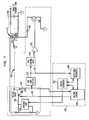
- FIG. 3shows a schematic block diagram of switcher 106 , line-side PSE control and power conditioning module 108 , power-isolation transformer 114 , and optical isolator 116 of conventional switch 100 of FIG. 1 .
- the elements in the upper half of the diagram that are to the left of transformer 114correspond to switcher 106 .
- Diode 302 and capacitor 304symbolically represent the line-side circuitry that provides the power conditioning functions of line-side PSE module 108
- the elements in the lower half of the diagramrepresent the line-side circuitry that provides the detection and classification functions of line-side PSE module 108 .
- switcher 106is a stand-alone, isolated, 48-volt, flyback switching supply that provides power to the PSE circuitry.
- Pulse Width Modulation (PWM) control logic 306is provided information regarding output voltage (via transformer winding 308 ) and drive current (via current-sensing resistor 310 and current reference amplifier 312 ) and uses this information to adjust the pulse width of the drive signal applied to the gate of power FET 314 , such that the desired voltage, with an appropriate current limit, is applied to the output.
- PWMPulse Width Modulation
- PSE control logic 316 of line-side PSE module 108performs the PoE detection and classification functions by sequentially providing two different fixed currents 318 and 320 onto the output, while the output voltage is measured by PSE control logic 316 . This is followed by the application of a fixed voltage 322 during which the current is measured by resistor 324 and amplifier 326 . During a normal power-up sequence, this is followed by PSE control logic 316 turning on power FET 328 and continuing to monitor current draw and voltage for health/fault/disconnect status.
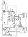
- FIG. 4shows the schematic block diagram of FIG. 3 annotated to indicate the migration of functions associated with particular elements in the line-side circuitry of PSE control and power conditioning module 108 of FIG. 1 to a combined switcher/PSE control module corresponding to a combined implementation of switcher 206 and PSE control module 210 of FIG. 2 , located on the isolated side of switch 200 .
- all of the line-side functions on the lower half of the diagrameither migrate to the isolated side or are eliminated (i.e., in the case of the optical isolator).
- FIG. 5shows a schematic block diagram of switcher 206 , line-side PSE power conditioning module 208 , isolated-side PSE control module 210 , and power-isolation transformer 214 of switch 200 of FIG. 2 , according to one possible embodiment of the present invention.
- the elements to the left of transformer 214correspond to switcher 206 and PSE control module 210
- diode 502 and capacitor 504symbolically represent the line-side circuitry that provides the power conditioning functions of PSE power conditioning module 208 .
- the PSE control module 210is shown being implemented as a set of logic separate from enhanced PWM control logic 506 of switcher 206 .
- a single logic devicecan be used to implement all functions to the left of power-isolation transformer 214 in FIG. 5 .
- PSE control module 210may be implemented in software and/or hardware in two or more different processing modules, including one or more processing modules that support multiple ports.
- a single logic deviceimplements all of the functions to the left of power-isolation transformer 214 that are associated with a single port, while another (shared) logic device, such as a microcontroller, implements additional functions that are associated with multiple ports, such as power balancing.
- PSE control module 210monitors the current and voltage from transformer 214 and current sense amplifier 512 and determines the appropriate PSE state for commanding enhanced PWM control logic 506 , which is enhanced (relative to PWM control logic 306 of FIG. 3 ) to support the detection and classification functions that migrated to the isolated side.
- FIG. 6shows a schematic block diagram of switcher 206 , line-side PSE power conditioning module 208 , isolated-side PSE control module 210 , and power-isolation transformer 214 of switch 200 of FIG. 2 , according to one possible low-voltage, mixed-signal, CMOS-technology embodiment of the present invention.
- the PSE circuitry of FIG. 6supports all three modes of operation described previously: detection, classification, and power conditioning (i.e., power on).
- PSE control module 210is implemented in digital logic as logic modules 602 - 610 .
- enhanced PWM control logic 506 of FIG. 5is implemented in digital logic as PWM control logic module 612 and Pulse Frequency Modulation (PFM) control logic module 614 , where PWM control logic module 612 controls pulse width modulation during the classification and power-on modes, and PFM control logic module 614 controls a PFM loop comprising detection (MOSFET) transistor 616 and current-limiting resistor 618 used during the detection mode.
- PFMPulse Frequency Modulation
- control signalswhereby sequencers (e.g., master sequencer 602 , detection sequencer 606 , and classification sequencer 608 ) can adjust (i) loop filter parameters (e.g., of PFM loop filter 622 and PWM loop filter 624 ), (ii) gains (e.g., of amplifiers 626 , 628 , and 630 ), or (iii) other parametric settings and (b) the control and test interface paths (e.g., from interface 632 ) that allow a user or surrogate processor to adjust voltages and current thresholds and to fine-tune timing, as appropriate.
- sequencerse.g., master sequencer 602 , detection sequencer 606 , and classification sequencer 608
- loop filter parameterse.g., of PFM loop filter 622 and PWM loop filter 624
- gainse.g., of amplifiers 626 , 628 , and 630
- other parametric settingse.g., of amplifiers 626 , 628
- FIG. 7shows a schematic block diagram of only those elements of FIG. 6 that are involved in the PSE detection mode of operation.
- master sequencer 602will set variable load 648 to mimic the expected detection load and then direct detection sequencer 606 to begin the detection process, which continues under the control of detection sequencer 606 .
- Detection sequencer 606directs voltage-control logic 604 to select and apply the first detection voltage point V 1 (e.g., nominally about 3 volts) as reference voltage 642 to be used by voltage-sense ADC (analog-to-digital converter) 634 of voltage-sense block 636 .
- V 1e.g., nominally about 3 volts
- ADCanalog-to-digital converter
- Detection sequencer 606then enables PFM control logic 614 , which sends short-duration pulses (e.g., typically about 100 to 500 ns long) to detection transistor 616 , which in turn sends precision low-current pulses to the isolated side of power transformer 214 , such that the resulting output voltage on the line side of power transformer 214 ramps up slowly.
- This transformer output voltageis sensed through third winding 638 in power transformer 214 by voltage-sense block 636 , in which ADC 634 compares sensed voltage 640 with reference voltage 642 .
- the resulting digitized signal 644 from ADC 634is appropriately filtered by PFM loop filter 622 in order to maintain loop stability, and the resulting filtered signal 646 is used by PFM control logic 614 to determine an appropriate pulse sequence that stabilizes the transformer output voltage at set point V 1 .
- Detection sequencer 606monitors the duration taken to arrive at set point V 1 . If the duration is too long, then detection sequencer 606 will time out, resetting the sequence. Such a time-out is indicative of an improper detection load on the output, such as the excessive capacitance required to be detected by the IEEE 802.3af PoE Standard. If the initial voltage set point V 1 is reached successfully (e.g., within a specified duration), then detection sequencer 606 will record the frequency (f 1 ) that PFM control logic 614 employed to stabilize at that level.
- Detection sequencer 606will then direct voltage-control logic 604 to select the second detection voltage point V 2 (e.g., nominally about 8 volts), and an analogous ramp-up sequence will be implemented until either set point V 2 is reached or a time-out occurs. If the second voltage set point V 2 is reached successfully, then detection sequencer 606 will record the frequency (f 2 ) that PFM control logic 614 employed to stabilize at that level.
- V 2e.g., nominally about 8 volts
- detection sequencer 606estimates the detection load from the difference between frequencies f 1 and f 2 . This is possible because the frequency, pulse width, peak current, and peak voltage at both set points V 1 and V 2 are known and can be used to calculate the average current and the average voltage. After compensating for parasitic losses, the value of the detection resistor in the PoE powered device can be calculated from the slope of the average voltage-current curve between set points V 1 and V 2 .
- master sequencer 602will wait a specified period (e.g., one half second) before re-initiating the detection sequence, as required by the IEEE 802.3af PoE Standard.
- FIG. 8shows a schematic block diagram of only those elements of FIG. 6 that are involved in the PSE classification mode of operation. If the detection process was successful, then master sequencer 602 will initiate a classification process under the control of classification sequencer 608 .
- Classification sequencer 608directs voltage-control logic 604 to select the classification voltage (e.g., nominally about 18 volts).
- the classification voltagee.g., nominally about 18 volts.
- switcher 206operates as a conventional current-mode, pulse-width modulated, switching power supply.
- Reference voltage 642 from voltage-control logic 604is compared by ADC 634 to sensed voltage 640 , which depends on the output voltage of power transformer 214 as reflected to third winding 638 .
- an adjustable matching load 648is utilized and set by master sequencer 602 to mimic the actual load expected in the classification mode. (Master sequencer 602 analogously controls variable load 648 during the detection and power-on modes.)
- ADC 634digitizes the error between the desired output voltage and the actual output voltage. This digitized error 644 is conditioned through PWM loop filter 624 to maintain loop stability. The resulting filtered error signal 650 is processed through digital current-limit function 652 and applied to current-sense block 654 , which senses the transformer current, to enable PWM control logic 612 to determine the peak current at which the pulse width modulator should turn off the power (MOSFET) transistor 656 .
- MOSFETpower
- the programmable current-limit function 652is set and monitored by fault monitor 610 to limit the average output current, e.g., to under 100 ma, as required by the IEEE 802.3af PoE Standard.
- Classification sequencer 608controls all aspects of voltage application, timing, and time-out processing for the PSE classification mode defined in the IEEE 802.3af PoE Standard. If the classification process completes successfully, then the current observed (i.e., the output of current-limit function 652 ) is reported to classification sequencer 608 , which determines the power class of the PoE powered device per the IEEE 802.3af PoE Standard.
- FIG. 9shows a schematic block diagram of only those elements of FIG. 6 that are involved in the PSE power-on mode of operation. Following the classification process, master sequencer 602 will initiate the power-on mode.
- Master sequencer 602will set variable load 648 to mimic the expected load and then direct voltage-control logic 604 to select the power-on voltage level (e.g., nominally about 48 volts).
- switcher 206operates as a conventional current-mode, pulse-width modulated, switching power supply.
- Reference voltage 642 from voltage-control logic 604is compared by ADC 634 to sensed voltage 640 , which depends on the output voltage of power transformer 214 as reflected to third winding 638 .
- ADC 634digitizes the error between the desired output and the actual output voltage. This digitized error 644 is conditioned through PWM loop filter 624 to maintain loop stability. The resulting filtered error signal 650 is processed through current-limit function 652 and applied to current-sense block 654 , which senses the transformer current, to enable PWM control logic 612 to determine the peak current at which the pulse width modulator should turn off the power (MOSFET) transistor 656 .
- MOSFETpower
- the programmable current-limit function 652is set and monitored by fault monitor 610 to limit the average output current, e.g., to nominally about 425 ma during initial power application (in-rush conditions) and then to a current limit dependent upon the results of the classification process, not to exceed nominally about 375 ma, as required by the IEEE 802.3af PoE Standard.
- Master sequencer 602controls all aspects of voltage application, timing, and time-out processing for the PSE power-on mode defined in the IEEE 802.3af PoE Standard.
- Various current limitssuch as Icut, Ilimit, and Iinrush, are programmed and monitored by fault monitor 610 using information received from current-limit function 652 . Appropriate levels of ramp-up rates, ramp-down rates, noise, and ripple currents are ensured by a combination of loop characteristics and hardware components utilized in the output circuits (e.g., power conditioning module 208 ).
- Off-load block 658 in power conditioning module 208senses when switcher 206 is shutting down in order to apply a small additional load to the output to ensure that the transformer output decays within the duration allotted by the IEEE 802.3af PoE Standard.
- the isolated-side PSE control module of the present inventioncan provide other PSE control functions that are normally implemented on the line side of certain conventional Ethernet switches.
- these functionsmay be those required by the IEEE 802.3af standard, and, in particular, by the requirements of FIG. 33-6 (entitled “PSE State Diagram”) and FIG. 33-7 (entitled “PSE Monitor Overload, Monitor Short, and Monitor MPS State Diagram”) of the IEEE 802.3af standard.
- the present inventionis described in the context of switches in which a 48-volt (differential) DC signal is applied to the secondary-side coils of two signal-isolation transformers, the invention is not necessarily so limited.
- the present inventionmay be implemented in the context of (1) DC power signals having voltage levels other than 48 volts, (2) non-differential (i.e., single-sided) DC power signals, and (3) even differential or single-sided AC power signals.
- the power signalsmay be provided to the cables via other means, such as direct connection to the connector.
- the present inventionmay be implemented in contexts other than switches, such as routers or other suitable apparatus.
- the present inventionmay be implemented as circuit-based processes, including possible implementation as a single integrated circuit (such as an ASIC or an FPGA), a multi-chip module, a single card, or a multi-card circuit pack.
- a single integrated circuitsuch as an ASIC or an FPGA
- a multi-chip modulesuch as a single card, or a multi-card circuit pack.
- various functions of circuit elementsmay also be implemented as processing steps in a software program.
- Such softwaremay be employed in, for example, a digital signal processor, micro-controller, or general-purpose computer.
Landscapes
- Engineering & Computer Science (AREA)
- Power Engineering (AREA)
- Dc Digital Transmission (AREA)
Abstract
Description
- This application claims the benefit of the filing date of U.S. provisional application No. 60/706,512, filed on Jul. 21, 05 as attorney docket no. Blaha 5-2, the teachings of which are incorporated herein by reference.
- 1. Field of the Invention
- The present invention relates to electronics, and, in particular, to Power Sourcing Equipment (PSE) for communication systems conforming to the IEEE 802.3 Ethernet and IEEE 802.3af Power over Ethernet (PoE) standards.
- 2. Description of the Related Art
FIG. 1 shows a block diagram of a portion of aconventional Ethernet switch 100 for a communication system that conforms to both the IEEE 802.3 Ethernet standard and the IEEE 802.3af PoE standard, the teachings of both of which are incorporated herein by reference. As shown inFIG. 1 , for each port in the switch,Ethernet switch 100 comprises Ethernet Physical-Layer (PHY)module 102, RJ-45 Ethernetconnector 104, 48-volt switcher 106, line-side PSE control andpower conditioning module 108, isolated-sidePSE control module 110, four-pair signal-isolation transformer 112, power-isolation transformer 114, andoptical isolator 116.- According to the IEEE 802.3 Ethernet standard, Ethernet PHY
module 102 communicates with a Media Access Controller (MAC) and switching function and processes incoming and outgoing differential data signals that are transmitted over an Ethernet cable (not shown) that is connected to switch100 at Ethernetconnector 104. According to the IEEE 802.3af PoE standard,switch 100 is a PSE-capable switch that can provide a 48-volt DC (cable power) signal on the Ethernet cable to power a so-called powered device (PD), such as an Internet Protocol (IP) telephone, such that the PD device does not require any additional power source to operate. The 48-volt DC signal is provided byswitcher 106 andmodules - Transformers112 and114 and
optical isolator 116 provide high-voltage electrical isolation between (1) circuitry, such as EthernetPHY module 102,switcher 106, andPSE control module 110, located on the so-called isolated side of switch100 (i.e., the primary side of the transformers) and (2) circuitry, such asEthernet connector 104 and PSE control andpower conditioning module 108, located on the so-called line side of switch100 (i.e., the transformers' secondary side), to protect the isolated-side circuitry from high voltages that might appear on the line side, such as those that can occur when lightening strikes near an Ethernet cable connected toconnector 104. Switcher 106 provides an AC power signal that is converted by power-isolation transformer 114 into a transformed AC power signal that can be converted by line-side PSE control andpower conditioning module 108 into the 48-volt (differential) DC signal that is applied to the center taps of the secondary-side coils of two of the four transformer pairs in signal-isolation transformer 112.- In the embodiment shown in
FIG. 1 , signal-isolation transformer 112 has four pairs of transformer coils, where the 48-volt DC signal is applied to the center taps of two of the four secondary-side coils. The IEEE 802.3 Ethernet standard also covers lower-rate (e.g., 10 Mbit and 100 Mbit) Ethernet systems that have only two pairs of coils, where two of the four wire pairs in the Ethernet cable are spares. According to the IEEE 802.3af PoE standard, the 48-volt DC signal can be applied directed to the two spare wire pairs to power a PD device. Although this specification describes Ethernet switches with ports having four pairs of transformer coils, the teachings of this specification apply equally well to Ethernet switches with ports having only two pairs of transformer coils and two spare wire pairs. - According to one conventional implementation, line-side PSE control and
power conditioning module 108 provides two PSE control functions (i.e., detection and classification) and three PSE power conditioning functions (i.e., rectification, filtering, and impedance control). - During detection, line-
side PSE module 108 sequentially applies two different, low-power signals to the transformer coils (either low-current or low-voltage depending on the implementation, such as a first low-power signal of approximately 3 volts followed by a second low-power signal of approximately 8 volts, instead of the full 48-volt DC signal) to enable line-side PSE module 108 to detect whether a valid PD device (which is required by the PoE standard to have a 25-Kohm impedance across the lines that provide the detection signal) is currently connected to Ethernetconnector 104 via an Ethernet cable. - If such a PD device is detected, then line-side PSE module108 (optionally) performs classification, during which line-
side PSE module 108 increases the level of the applied signal to approximately 18 volts and measures the PD signature current draw to determine the power classification of the detected PD device. - If a PD device is detected and (optionally) classified, then line-
side PSE module 108 performs power conditioning, during which line-side PSE module 108 generates and applies the appropriate 48-volt DC signal viaconnector 104 to the Ethernet cable to power the PD device. This power conditioning function involves rectification and filtering of the transformed AC signal that is applied to line-side PSE module 108 from the secondary side oftransformer 114 to generate the 48-volt DC signal. The power conditioning function also involves impedance control for the 48-volt DC signal. If no PD device is detected, then line-side PSE module 108 does not generate and apply a 48-volt DC signal to the Ethernet cable. - Depending on the particular implementation,
switch 100 may be configured to support multiple Ethernet ports, like the port associated with Ethernetconnector 104. According to one such conventional implementation, line-side PSE control andpower conditioning module 108 is implemented as a relatively large integrated circuit (IC) that is capable of simultaneously supporting four different Ethernet ports. Examples of such line-side PSE control and power conditioning modules are: - The 12-channel PoE Manager, Product No. PD64012, sold by PowerDsine Ltd. of Israel;
- The Quad Integrated Power Sourcing Equipment Power Manager, Product No. TPS2384, sold by Texas Instruments Incorporated of Dallas, Tex.; and
- The Quad IEEE 802.3af Power over Ethernet Controller with Integrated Detection module, Product No. LTC4258, sold by Linear Technology Corporation of Milpitas, Calif.
- These conventional PSE control and power conditioning modules provide a certain (relatively limited) level of operating functionality. In certain conventional Ethernet switches, such as
switch 100 ofFIG. 1 , additional (e.g., switch-vendor value-added) functions are provided by isolated-sidePSE control module 110, which is typically implemented using a microcontroller. One exemplary additional function that may be provided by isolated-sidePSE control module 110 is power balancing between multiple (e.g., as many as 48 or more) PD devices connected to a single Ethernet switch, where power balancing is based on the results of the PD power classification performed on each PD device. To implement this additional operating functionality, isolated-sidePSE control module 110 receives (explicit) information about the status of the operations at line-side PSE module 108 viaoptical isolator 116 and transmits control signals to control the operations at line-side PSE module 108 viaoptical isolator 116. - Such a conventional configuration for
switch 100 has a number of disadvantages. First of all, there is a considerable dollar cost to providing all of this circuitry associated with these functions. Furthermore, when two or more PD devices are connected to different Ethernet connectors supported by a single line-side PSE control and power conditioning module, there is no electrical isolation to protect the rest of the PD devices from a lightening strike near any one of the PD devices. - In one embodiment, the present invention is an apparatus having an isolated side and a line side. The apparatus comprises a physical-layer module, a power switcher, a power conditioning module, and a control module. The physical-layer module is (1) located on the isolated side of the apparatus, (2) adapted to be electrically coupled via a signal-isolation transformer to a cable connector located on the line side of the apparatus, and (3) adapted to process signals transmitted over the cable. The power switcher is located on the isolated side of the apparatus. The power conditioning module is (1) located on the line side of the apparatus, (2) electrically coupled to the power switcher via a power-isolation transformer adapted to convert an AC power signal received from the power switcher into a transformed AC power signal, and (3) adapted to convert the transformed AC power signal into a cable power signal to be supplied via the connector to the cable in order to power a cable-powered device connected to the cable. The control module is located on the isolated side of the apparatus and adapted to perform a detection function in which the control module determines whether or not a cable-powered device is connected to the cable.
- In another embodiment, the present invention is a method for powering a cable-powered device using an apparatus having a line side and an isolated side, wherein the cable-powered device is connected to the line-side of the apparatus via a cable. According to the method, signals transmitted from the cable-powered device over the cable are received at the line side of the apparatus. The signals from the cable-powered device are (1) transmitted from the line side of the apparatus to the isolated side of the apparatus via a signal-isolation transformer located between the line side of the apparatus and the isolated side of the apparatus and (2) processed on the isolated side of the apparatus. An AC power signal on the isolated side of the apparatus is converted into a transformed AC power signal on the line side of the apparatus via a power-isolation transformer located between the line side of the apparatus and the isolated side of the apparatus. The transformed AC power signal is converted, on the line side of the apparatus, into a cable power signal, which is supplied to the cable in order to power the cable-powered device. A determination is made, on the isolated side of the apparatus, that the cable-powered device is connected to the cable based on signals received at the isolated side of the apparatus from the line side of the apparatus via the power-isolation transformer.
- Other aspects, features, and advantages of the present invention will become more fully apparent from the following detailed description, the appended claims, and the accompanying drawings in which like reference numerals identify similar or identical elements.
FIG. 1 shows a block diagram of a portion of a conventional Ethernet switch for a communication system that conforms to both the IEEE 802.3 Ethernet standard and the IEEE 802.3af PoE standard;FIG. 2 shows a block diagram of a portion of an Ethernet switch for a communication system that conforms to the IEEE 802.3 Ethernet and 802.3af PoE standards, according to one embodiment of the present invention;FIG. 3 shows a schematic block diagram of the switcher, the line-side PSE control and power conditioning module, the power-isolation transformer, and the optical isolator of the conventional Ethernet switch ofFIG. 1 ;FIG. 4 shows the schematic block diagram ofFIG. 3 annotated to indicate the migration of functions associated with particular elements in the line-side circuitry of the PSE control and power conditioning module ofFIG. 1 to a combined switcher/PSE control module corresponding to a combined implementation of the switcher and the isolated-side PSE control module ofFIG. 2 ;FIG. 5 shows a schematic block diagram of the switcher, the line-side PSE power conditioning module, the isolated-side PSE control module, and the power-isolation transformer of the Ethernet switch ofFIG. 2 , according to one possible embodiment of the present invention;FIG. 6 shows a schematic block diagram of the switcher, the line-side PSE power conditioning module, the isolated-side PSE control module, and the power-isolation transformer of the Ethernet switch ofFIG. 2 , according to one possible low-voltage, mixed-signal, CMOS-technology embodiment of the present invention;FIG. 7 shows a schematic block diagram of only those elements ofFIG. 6 that are involved in the PSE detection mode of operation;FIG. 8 shows a schematic block diagram of only those elements ofFIG. 6 that are involved in the PSE classification mode of operation; andFIG. 9 shows a schematic block diagram of only those elements ofFIG. 6 that are involved in the PSE power-on mode of operation.FIG. 2 shows a block diagram of a portion of anEthernet switch 200 for a communication system that conforms to the IEEE 802.3 Ethernet and the IEEE 802.3af Power over Ethernet (PoE) standards, according to one embodiment of the present invention. As shown inFIG. 2 ,Ethernet switch 200 comprisesEthernet PHY module 202, RJ-45Ethernet connector 204, 48-volt switcher 206, line-side PSEpower conditioning module 208, isolated-sidePSE control module 210, four-pair signal-isolation transformer 212, and power-isolation transformer 214, whereswitcher 206 andpower conditioning module 208 function together as an isolated switching power supply.Ethernet PHY module 202,connector 204, andtransformers conventional switch 100 ofFIG. 1 . Note that, unlikeswitch 100 ofFIG. 1 ,switch 200 does not have any optical isolator.- According to this embodiment of the present invention, the PSE detection and (optional) classification functions that were performed by line-side PSE control and
power conditioning module 108 ofFIG. 1 and all of the PSE control functions that were performed by isolated-sidePSE control module 110 ofFIG. 1 are now performed by isolated-sidePSE control module 210 ofFIG. 2 . The only PSE functions that remain on the line side ofswitch 200 ofFIG. 2 are the power conditioning functions implemented by PSEpower conditioning module 208 ofFIG. 2 . These power conditioning functions include, but are not limited to, rectification, filtering, and impedance control. Note that, in this embodiment, isolated-sidePSE control module 210 does not receive any explicit information from the line side ofswitch 200 about the status of the operations at line-side PSEpower conditioning module 208. - The migration of the PSE detection and classification functions from the line side of
switch 100 to the isolated side ofswitch 200 is enabled by the fact that all of the information needed to implement those functions appears on both sides (i.e., on both the primary- and secondary-side coils) of power-isolation transformer 214. Note thatEthernet PHY module 202,switcher 206, andPSE control module 210 are preferably, but do not have to be, implemented in a combined manner on a single integrated circuit. - This function migration from line side to isolated side also enables practical implementation of a separate line-side PSE power conditioning module, similar to
module 208 ofFIG. 2 , for each Ethernet connector, similar toconnector 204, supported byswitch 200. As such, a switch of the present invention can be configured with multiple Ethernet ports, while providing electrical isolation between all of the Ethernet ports. In particular, the high voltage associated with a lightening strike near an Ethernet cable connected to one of the Ethernet ports will not reach any of the other Ethernet ports (or their associated cables and PD devices). In one possible implementation, a single module, like isolated-sidePSE control module 210 ofFIG. 2 , can be designed to support multiple Ethernet ports, with each port having its own switcher (like switcher206), transformer (like transformer214), PSE power conditioning module (like module208) and Ethernet connector (like connector204), while still allowing very high levels of integration. FIG. 3 shows a schematic block diagram ofswitcher 106, line-side PSE control andpower conditioning module 108, power-isolation transformer 114, andoptical isolator 116 ofconventional switch 100 ofFIG. 1 . InFIG. 3 , the elements in the upper half of the diagram that are to the left oftransformer 114 correspond toswitcher 106.Diode 302 andcapacitor 304 symbolically represent the line-side circuitry that provides the power conditioning functions of line-side PSE module 108, while the elements in the lower half of the diagram represent the line-side circuitry that provides the detection and classification functions of line-side PSE module 108.- As represented in the upper half of
FIG. 3 ,switcher 106 is a stand-alone, isolated, 48-volt, flyback switching supply that provides power to the PSE circuitry. Pulse Width Modulation (PWM)control logic 306 is provided information regarding output voltage (via transformer winding308) and drive current (via current-sensingresistor 310 and current reference amplifier312) and uses this information to adjust the pulse width of the drive signal applied to the gate ofpower FET 314, such that the desired voltage, with an appropriate current limit, is applied to the output. - As represented in the lower half of
FIG. 3 , optionally under the control of isolated-sidePSE control module 110,PSE control logic 316 of line-side PSE module 108 performs the PoE detection and classification functions by sequentially providing two differentfixed currents PSE control logic 316. This is followed by the application of a fixedvoltage 322 during which the current is measured byresistor 324 andamplifier 326. During a normal power-up sequence, this is followed byPSE control logic 316 turning onpower FET 328 and continuing to monitor current draw and voltage for health/fault/disconnect status. FIG. 4 shows the schematic block diagram ofFIG. 3 annotated to indicate the migration of functions associated with particular elements in the line-side circuitry of PSE control andpower conditioning module 108 ofFIG. 1 to a combined switcher/PSE control module corresponding to a combined implementation ofswitcher 206 andPSE control module 210 ofFIG. 2 , located on the isolated side ofswitch 200. As represented inFIG. 4 , all of the line-side functions on the lower half of the diagram either migrate to the isolated side or are eliminated (i.e., in the case of the optical isolator).- In particular, as represented in
FIG. 4 : - The functions of
power FET 328 are migrated topower FET 314; - The functions of
current sources resistor 324, andamplifier 326 are migrated toresistor 310,amplifier 312, andPWM control logic 306; - The functions of
PSE control logic 316 are migrated toPWM control logic 306; - The functions of
voltage source 322 are migrated tovoltage reference 330; and - The detection and classification power provided to the Ethernet connector is migrated to the output of the line-side power conditioning function.
- The functions of
FIG. 5 shows a schematic block diagram ofswitcher 206, line-side PSEpower conditioning module 208, isolated-sidePSE control module 210, and power-isolation transformer 214 ofswitch 200 ofFIG. 2 , according to one possible embodiment of the present invention. InFIG. 5 , the elements to the left oftransformer 214 correspond to switcher206 andPSE control module 210, whilediode 502 and capacitor504 symbolically represent the line-side circuitry that provides the power conditioning functions of PSEpower conditioning module 208. In this particular implementation, thePSE control module 210 is shown being implemented as a set of logic separate from enhancedPWM control logic 506 ofswitcher 206. In a combined implementation, a single logic device can be used to implement all functions to the left of power-isolation transformer 214 inFIG. 5 .- Alternatively, the functions of
PSE control module 210 may be implemented in software and/or hardware in two or more different processing modules, including one or more processing modules that support multiple ports. For example, in one possible implementation, a single logic device implements all of the functions to the left of power-isolation transformer 214 that are associated with a single port, while another (shared) logic device, such as a microcontroller, implements additional functions that are associated with multiple ports, such as power balancing. - In any case,
PSE control module 210 monitors the current and voltage fromtransformer 214 andcurrent sense amplifier 512 and determines the appropriate PSE state for commanding enhancedPWM control logic 506, which is enhanced (relative toPWM control logic 306 ofFIG. 3 ) to support the detection and classification functions that migrated to the isolated side. FIG. 6 shows a schematic block diagram ofswitcher 206, line-side PSEpower conditioning module 208, isolated-sidePSE control module 210, and power-isolation transformer 214 ofswitch 200 ofFIG. 2 , according to one possible low-voltage, mixed-signal, CMOS-technology embodiment of the present invention. The PSE circuitry ofFIG. 6 supports all three modes of operation described previously: detection, classification, and power conditioning (i.e., power on).- In this embodiment,
PSE control module 210 is implemented in digital logic as logic modules602-610. Similarly, enhancedPWM control logic 506 ofFIG. 5 is implemented in digital logic as PWMcontrol logic module 612 and Pulse Frequency Modulation (PFM)control logic module 614, where PWMcontrol logic module 612 controls pulse width modulation during the classification and power-on modes, and PFMcontrol logic module 614 controls a PFM loop comprising detection (MOSFET)transistor 616 and current-limitingresistor 618 used during the detection mode. - When power is first applied to the PSE circuitry of
FIG. 6 , analog bias circuitry is stabilized, clocks (e.g., from clock generator620) are started, and all circuitry is reset or initialized. Following initialization, operation of the PSE circuitry is under the control ofmaster sequencer 602, which will determine the mode of operation for the PSE circuitry. Per the IEEE 802.3af PoE Standard, the basic sequence of operation is: (1) detection, (2) classification, and (3) power conditioning. Provisions may be made for various fault conditions and/or user interventions to override this basic sequencing. - Not explicitly shown in
FIG. 6 (or in subsequentFIGS. 7-9 ) are paths whereby digital logic functions are clocked at appropriate times taking into account proper settling of the sensed levels. Also not explicitly shown are (a) control signals, whereby sequencers (e.g.,master sequencer 602,detection sequencer 606, and classification sequencer608) can adjust (i) loop filter parameters (e.g., ofPFM loop filter 622 and PWM loop filter624), (ii) gains (e.g., ofamplifiers - Operation of the PSE circuitry of
FIG. 6 for the three different modes of operation (i.e., detection, classification, and power conditioning) is described below in the context ofFIGS. 7-9 , respectively. FIG. 7 shows a schematic block diagram of only those elements ofFIG. 6 that are involved in the PSE detection mode of operation. Following initialization,master sequencer 602 will setvariable load 648 to mimic the expected detection load and then directdetection sequencer 606 to begin the detection process, which continues under the control ofdetection sequencer 606.Detection sequencer 606 directs voltage-control logic 604 to select and apply the first detection voltage point V1 (e.g., nominally about 3 volts) asreference voltage 642 to be used by voltage-sense ADC (analog-to-digital converter)634 of voltage-sense block 636.Detection sequencer 606 then enablesPFM control logic 614, which sends short-duration pulses (e.g., typically about 100 to 500 ns long) todetection transistor 616, which in turn sends precision low-current pulses to the isolated side ofpower transformer 214, such that the resulting output voltage on the line side ofpower transformer 214 ramps up slowly. This transformer output voltage is sensed through third winding638 inpower transformer 214 by voltage-sense block 636, in whichADC 634 compares sensedvoltage 640 withreference voltage 642.- The resulting
digitized signal 644 fromADC 634 is appropriately filtered byPFM loop filter 622 in order to maintain loop stability, and the resulting filteredsignal 646 is used byPFM control logic 614 to determine an appropriate pulse sequence that stabilizes the transformer output voltage at set point V1. Detection sequencer 606 monitors the duration taken to arrive at set point V1. If the duration is too long, thendetection sequencer 606 will time out, resetting the sequence. Such a time-out is indicative of an improper detection load on the output, such as the excessive capacitance required to be detected by the IEEE 802.3af PoE Standard. If the initial voltage set point V1 is reached successfully (e.g., within a specified duration), thendetection sequencer 606 will record the frequency (f1) thatPFM control logic 614 employed to stabilize at that level.Detection sequencer 606 will then direct voltage-control logic 604 to select the second detection voltage point V2 (e.g., nominally about 8 volts), and an analogous ramp-up sequence will be implemented until either set point V2 is reached or a time-out occurs. If the second voltage set point V2 is reached successfully, thendetection sequencer 606 will record the frequency (f2) thatPFM control logic 614 employed to stabilize at that level.- If the detection process gets this far without timing out, then
detection sequencer 606 estimates the detection load from the difference between frequencies f1 and f2. This is possible because the frequency, pulse width, peak current, and peak voltage at both set points V1 and V2 are known and can be used to calculate the average current and the average voltage. After compensating for parasitic losses, the value of the detection resistor in the PoE powered device can be calculated from the slope of the average voltage-current curve between set points V1 and V2. - If the detection mode was not successful (e.g., detection sequencer timed out while trying to achieve either set point V1 or set point V2), then
master sequencer 602 will wait a specified period (e.g., one half second) before re-initiating the detection sequence, as required by the IEEE 802.3af PoE Standard. FIG. 8 shows a schematic block diagram of only those elements ofFIG. 6 that are involved in the PSE classification mode of operation. If the detection process was successful, thenmaster sequencer 602 will initiate a classification process under the control ofclassification sequencer 608.Classification sequencer 608 directs voltage-control logic 604 to select the classification voltage (e.g., nominally about 18 volts). During classification,switcher 206 operates as a conventional current-mode, pulse-width modulated, switching power supply.Reference voltage 642 from voltage-control logic 604 is compared byADC 634 to sensedvoltage 640, which depends on the output voltage ofpower transformer 214 as reflected to third winding638.- To ensure that the voltage from third winding638 is closely representative of the actual transformer output voltage (in order to maintain high accuracy), an
adjustable matching load 648 is utilized and set bymaster sequencer 602 to mimic the actual load expected in the classification mode. (Master sequencer 602 analogously controlsvariable load 648 during the detection and power-on modes.) ADC 634 digitizes the error between the desired output voltage and the actual output voltage. Thisdigitized error 644 is conditioned throughPWM loop filter 624 to maintain loop stability. The resulting filterederror signal 650 is processed through digital current-limit function 652 and applied to current-sense block 654, which senses the transformer current, to enablePWM control logic 612 to determine the peak current at which the pulse width modulator should turn off the power (MOSFET)transistor 656.- In the PSE classification mode, the programmable current-
limit function 652 is set and monitored byfault monitor 610 to limit the average output current, e.g., to under 100 ma, as required by the IEEE 802.3af PoE Standard. Classification sequencer 608 controls all aspects of voltage application, timing, and time-out processing for the PSE classification mode defined in the IEEE 802.3af PoE Standard. If the classification process completes successfully, then the current observed (i.e., the output of current-limit function652) is reported toclassification sequencer 608, which determines the power class of the PoE powered device per the IEEE 802.3af PoE Standard.FIG. 9 shows a schematic block diagram of only those elements ofFIG. 6 that are involved in the PSE power-on mode of operation. Following the classification process,master sequencer 602 will initiate the power-on mode.Master sequencer 602 will setvariable load 648 to mimic the expected load and then direct voltage-control logic 604 to select the power-on voltage level (e.g., nominally about 48 volts). During power-on,switcher 206 operates as a conventional current-mode, pulse-width modulated, switching power supply.Reference voltage 642 from voltage-control logic 604 is compared byADC 634 to sensedvoltage 640, which depends on the output voltage ofpower transformer 214 as reflected to third winding638.ADC 634 digitizes the error between the desired output and the actual output voltage. Thisdigitized error 644 is conditioned throughPWM loop filter 624 to maintain loop stability. The resulting filterederror signal 650 is processed through current-limit function 652 and applied to current-sense block 654, which senses the transformer current, to enablePWM control logic 612 to determine the peak current at which the pulse width modulator should turn off the power (MOSFET)transistor 656.- In the PSE power-on mode, the programmable current-
limit function 652 is set and monitored byfault monitor 610 to limit the average output current, e.g., to nominally about 425 ma during initial power application (in-rush conditions) and then to a current limit dependent upon the results of the classification process, not to exceed nominally about 375 ma, as required by the IEEE 802.3af PoE Standard. Master sequencer 602 controls all aspects of voltage application, timing, and time-out processing for the PSE power-on mode defined in the IEEE 802.3af PoE Standard. Various current limits, such as Icut, Ilimit, and Iinrush, are programmed and monitored byfault monitor 610 using information received from current-limit function 652. Appropriate levels of ramp-up rates, ramp-down rates, noise, and ripple currents are ensured by a combination of loop characteristics and hardware components utilized in the output circuits (e.g., power conditioning module208).- Off-
load block 658 inpower conditioning module 208 senses whenswitcher 206 is shutting down in order to apply a small additional load to the output to ensure that the transformer output decays within the duration allotted by the IEEE 802.3af PoE Standard. - Depending on the particular implementation, the isolated-side PSE control module of the present invention can provide other PSE control functions that are normally implemented on the line side of certain conventional Ethernet switches. In general, these functions may be those required by the IEEE 802.3af standard, and, in particular, by the requirements of
FIG. 33-6 (entitled “PSE State Diagram”) andFIG. 33-7 (entitled “PSE Monitor Overload, Monitor Short, and Monitor MPS State Diagram”) of the IEEE 802.3af standard. - Although the present invention has been described in the context of communication systems conforming to the IEEE 802.3 Ethernet and IEEE 802.3af PoE standards, the invention is not necessarily limited to communication systems that conform to either or both of those two standards. Moreover, as those standards may evolve over time, it is expected that implementations of the present invention can also evolve in a corresponding manner.
- Although the present invention is described in the context of switches in which a 48-volt (differential) DC signal is applied to the secondary-side coils of two signal-isolation transformers, the invention is not necessarily so limited. For example, the present invention may be implemented in the context of (1) DC power signals having voltage levels other than 48 volts, (2) non-differential (i.e., single-sided) DC power signals, and (3) even differential or single-sided AC power signals. Moreover, the power signals may be provided to the cables via other means, such as direct connection to the connector. Furthermore, the present invention may be implemented in contexts other than switches, such as routers or other suitable apparatus.
- The present invention may be implemented as circuit-based processes, including possible implementation as a single integrated circuit (such as an ASIC or an FPGA), a multi-chip module, a single card, or a multi-card circuit pack. As would be apparent to one skilled in the art, various functions of circuit elements may also be implemented as processing steps in a software program. Such software may be employed in, for example, a digital signal processor, micro-controller, or general-purpose computer.
- It will be further understood that various changes in the details, materials, and arrangements of the parts which have been described and illustrated in order to explain the nature of this invention may be made by those skilled in the art without departing from the scope of the invention as expressed in the following claims.
- Reference herein to “one embodiment” or “an embodiment” means that a particular feature, structure, or characteristic described in connection with the embodiment can be included in at least one embodiment of the invention. The appearances of the phrase “in one embodiment” in various places in the specification are not necessarily all referring to the same embodiment, nor are separate or alternative embodiments necessarily mutually exclusive of other embodiments. The same applies to the term “implementation.”
Claims (20)
Priority Applications (1)
| Application Number | Priority Date | Filing Date | Title |
|---|---|---|---|
| US11/369,057US7685440B2 (en) | 2005-07-21 | 2006-03-06 | Switch with fully isolated power sourcing equipment control |
Applications Claiming Priority (2)
| Application Number | Priority Date | Filing Date | Title |
|---|---|---|---|
| US70651205P | 2005-07-21 | 2005-07-21 | |
| US11/369,057US7685440B2 (en) | 2005-07-21 | 2006-03-06 | Switch with fully isolated power sourcing equipment control |
Publications (2)
| Publication Number | Publication Date |
|---|---|
| US20070019445A1true US20070019445A1 (en) | 2007-01-25 |
| US7685440B2 US7685440B2 (en) | 2010-03-23 |
Family
ID=37678887
Family Applications (1)
| Application Number | Title | Priority Date | Filing Date |
|---|---|---|---|
| US11/369,057Expired - Fee RelatedUS7685440B2 (en) | 2005-07-21 | 2006-03-06 | Switch with fully isolated power sourcing equipment control |
Country Status (1)
| Country | Link |
|---|---|
| US (1) | US7685440B2 (en) |
Cited By (20)
| Publication number | Priority date | Publication date | Assignee | Title |
|---|---|---|---|---|
| US20060181817A1 (en)* | 2005-01-31 | 2006-08-17 | Eli Ohana | Means for preventing unintended powering |
| US20070041568A1 (en)* | 2005-08-19 | 2007-02-22 | Sajol Ghoshal | Modular Power Converter |
| US20070077819A1 (en)* | 2005-10-05 | 2007-04-05 | Mitel Networks Corporation | Midspan power delivery system for reduced emissions |
| US20080082695A1 (en)* | 2006-09-29 | 2008-04-03 | Broadcom Corporation | Virtual interface to the PoE device through an expanded registered map in a networking device such as a PHY |
| US20080080105A1 (en)* | 2006-09-29 | 2008-04-03 | Agere Systems Inc. | Isolated switched maintain power signature (mps) and fault monitoring for power over ethernet |
| US20080238656A1 (en)* | 2007-03-28 | 2008-10-02 | Agere Systems Inc. | Isolated resistive signature detection for powered devices |
| US20080238447A1 (en)* | 2007-03-26 | 2008-10-02 | Agere Systems Inc. | Isolated capacitive signature detection for powered devices |
| WO2008011529A3 (en)* | 2006-07-21 | 2008-11-13 | Akros Silicon Inc | Over-voltage protection circuit |
| US20090015237A1 (en)* | 2007-07-11 | 2009-01-15 | Cisco Technology, Inc. | Classification technique for powered devices using selective frequency filtering |
| US20090172656A1 (en)* | 2007-12-31 | 2009-07-02 | Silicon Laboratories Inc. | Circuit device and method of providing a programmable power supply |
| US20090168462A1 (en)* | 2007-12-26 | 2009-07-02 | Silicon Laboratories Inc. | Circuit device and method of providing feedback across an isolation barrier |
| US20090323717A1 (en)* | 2008-06-30 | 2009-12-31 | Silicon Laboratories Inc. | System and method of providing electrical isolation |
| US20090327558A1 (en)* | 2008-06-30 | 2009-12-31 | Silicon Laboratories Inc. | System and method of providing electrical isolation |
| US7643315B2 (en) | 2006-08-22 | 2010-01-05 | Agere Systems, Inc. | Programmable feedback voltage pulse sampling for switched power supplies |
| US20100007334A1 (en)* | 2008-07-08 | 2010-01-14 | Silicon Laboratories Inc. | Power sourcing equipment device and method of providing a power supply to a powered device |
| US7685440B2 (en) | 2005-07-21 | 2010-03-23 | Agere Systems Inc. | Switch with fully isolated power sourcing equipment control |
| US20100218003A1 (en)* | 2005-06-16 | 2010-08-26 | Agere Systems Inc. | Transformerless power over ethernet system |
| TWI393317B (en)* | 2009-05-27 | 2013-04-11 | Korenix Technology Co Ltd | Power over ethernet system having hi-pot isolation and automatic output power adjustment with thermal control |
| US20150311223A1 (en)* | 2013-12-04 | 2015-10-29 | Boe Technology Group Co., Ltd. | Thin film transistor array substrate and manufacturing method thereof, and display device |
| US20160330793A1 (en)* | 2015-05-06 | 2016-11-10 | Crystal Instruments Corporation | Synchronized measurement device using local area network with ethernet messaging |
Families Citing this family (3)
| Publication number | Priority date | Publication date | Assignee | Title |
|---|---|---|---|---|
| US20080048779A1 (en)* | 2006-05-16 | 2008-02-28 | Crawley Philip J | Active emi suppression circuit |
| US8108699B2 (en)* | 2008-09-30 | 2012-01-31 | Broadcom Corporation | System and method for power over ethernet configuration for a power sourcing equipment using a network profile |
| US8214680B1 (en)* | 2009-02-12 | 2012-07-03 | Hewlett-Packard Development Company, L.P. | PoE powered management circuitry using out-of-band data port |
Citations (37)
| Publication number | Priority date | Publication date | Assignee | Title |
|---|---|---|---|---|
| US4004104A (en)* | 1974-05-07 | 1977-01-18 | Jeumont-Schneider | System for feeding in continuous current to a telephone line |
| US4761702A (en)* | 1986-04-22 | 1988-08-02 | Mitel Corporation | CMOS latch-up recovery circuit |
| US5138543A (en)* | 1991-05-31 | 1992-08-11 | At&T Bell Laboratories | Output voltage estimating circuit for a power converter having galvanic isolation between input and output circuits |
| US5305192A (en)* | 1991-11-01 | 1994-04-19 | Linear Technology Corporation | Switching regulator circuit using magnetic flux-sensing |
| US5402329A (en)* | 1992-12-09 | 1995-03-28 | Ernest H. Wittenbreder, Jr. | Zero voltage switching pulse width modulated power converters |
| US5461303A (en)* | 1994-01-31 | 1995-10-24 | Power Integrations, Inc. | Power factor correction precompensation circuit |
| US5757625A (en)* | 1995-10-02 | 1998-05-26 | U.S. Philips Corporation | Switched mode power supply with transformer and feedback via primary winding |
| US5991172A (en)* | 1996-06-21 | 1999-11-23 | Delta Electronics, Inc. | AC/DC flyback converter with improved power factor and reduced switching loss |
| US6343026B1 (en)* | 2000-11-09 | 2002-01-29 | Artesyn Technologies, Inc. | Current limit circuit for interleaved converters |
| US6640308B1 (en)* | 1999-04-16 | 2003-10-28 | Invensys Systems, Inc. | System and method of powering and communicating field ethernet device for an instrumentation and control using a single pair of powered ethernet wire |
| US6650070B1 (en)* | 2002-07-25 | 2003-11-18 | Varon Lighting, Inc. | Point of use lighting controller |
| US20050169017A1 (en)* | 2001-11-29 | 2005-08-04 | Muegge Mark R. | Methods for digital regulation of power converters using primary-only feedback |
| US6958920B2 (en)* | 2003-10-02 | 2005-10-25 | Supertex, Inc. | Switching power converter and method of controlling output voltage thereof using predictive sensing of magnetic flux |
| US6967472B2 (en)* | 2002-01-17 | 2005-11-22 | Power Integrations, Inc. | Method and apparatus for maintaining an approximate constant current output characteristic in a switched mode power supply |
| US6972969B1 (en)* | 2004-08-19 | 2005-12-06 | Iwatt, Inc. | System and method for controlling current limit with primary side sensing |
| US20050285587A1 (en)* | 2004-06-29 | 2005-12-29 | Ta-Yung Yang | Apparatus and method thereof for measuring output current from primary side of power converter |
| US20060002155A1 (en)* | 2003-06-30 | 2006-01-05 | Anatoly Shteynberg | System and method for input current shaping in a power converter |
| US6995991B1 (en)* | 2004-07-20 | 2006-02-07 | System General Corp. | PWM controller for synchronous rectifier of flyback power converter |
| US20060034102A1 (en)* | 2004-08-12 | 2006-02-16 | Ta-Yung Yang | Close-loop pwm controller for primary-side controlled power converters |
| US20060056204A1 (en)* | 2004-09-16 | 2006-03-16 | Ta-Yung Yang | Switching control circuit for primary-side controlled power converters |
| US20060080723A1 (en)* | 2004-10-12 | 2006-04-13 | Thp Technology Co., Ltd. | System and method for enabling TV and computer to process digital audio/video signal simultaneously |
| US7054170B2 (en)* | 2004-01-05 | 2006-05-30 | System General Corp. | Power-mode controlled power converter |
| US7057907B2 (en)* | 2003-11-21 | 2006-06-06 | Fairchild Semiconductor Corporation | Power converter having improved control |
| US7061780B2 (en)* | 2004-09-09 | 2006-06-13 | System General Corp. | Switching control circuit with variable switching frequency for primary-side-controlled power converters |
| US7142437B2 (en)* | 2002-11-05 | 2006-11-28 | Power Integrations, Inc. | Method and apparatus for output voltage regulation in primary control switched mode power supplies |
| US20070024213A1 (en)* | 2005-07-28 | 2007-02-01 | Synditec, Inc. | Pulsed current averaging controller with amplitude modulation and time division multiplexing for arrays of independent pluralities of light emitting diodes |
| US7196503B2 (en)* | 2004-07-26 | 2007-03-27 | Intersil Americas, Inc. | Current averaging circuit for a PWM power converter |
| US20070070664A1 (en)* | 2005-09-27 | 2007-03-29 | Keming Chen | Bi-directional current sensing circuit |
| US7259972B2 (en)* | 2004-10-07 | 2007-08-21 | System General Corporation | Primary-side-control power converter having a switching controller using frequency hopping and voltage and current control loops |
| US7280376B2 (en)* | 2004-10-15 | 2007-10-09 | Dell Products L.P. | Primary side voltage sense for AC/DC power supplies capable of compensation for a voltage drop in the secondary |
| US20080049459A1 (en)* | 2006-08-22 | 2008-02-28 | Agere Systems Inc. | Programmable feedback voltage pulse sampling for switched power supplies |
| US20080071260A1 (en)* | 2006-09-15 | 2008-03-20 | Shores Ronald B | Electrosurgical generator and method using a high permeability, high resistivity transformer |
| US7362593B2 (en)* | 2004-09-16 | 2008-04-22 | System General Corp. | Switching control circuit having off-time modulation to improve efficiency of primary-side controlled power supply |
| US20080192514A1 (en)* | 2007-02-08 | 2008-08-14 | Linear Technology Corporation | Adaptive output current control for switching circuits |
| US20080238447A1 (en)* | 2007-03-26 | 2008-10-02 | Agere Systems Inc. | Isolated capacitive signature detection for powered devices |
| US7471522B2 (en)* | 2006-08-03 | 2008-12-30 | Linear Technology Corporation | Light load regulator for isolated flyback converter |
| US7486528B2 (en)* | 2006-08-15 | 2009-02-03 | System General Corp. | Linear-predict sampling for measuring demagnetized voltage of transformer |
Family Cites Families (4)
| Publication number | Priority date | Publication date | Assignee | Title |
|---|---|---|---|---|
| JP2001203085A (en) | 2000-01-17 | 2001-07-27 | Japan Storage Battery Co Ltd | Lighting device of discharge lamp |
| US20030080723A1 (en) | 2001-10-31 | 2003-05-01 | Qing Chen | Average current estimation scheme for switching mode power supplies |
| DE10332841A1 (en) | 2003-07-18 | 2005-02-17 | Siemens Ag | Power supply circuit arrangement for use in supplying a load over the twisted pair leads of a local area network, whereby two electronic chokes are used per data lead pair to permit supply voltage extraction |
| US7685440B2 (en) | 2005-07-21 | 2010-03-23 | Agere Systems Inc. | Switch with fully isolated power sourcing equipment control |
- 2006
- 2006-03-06USUS11/369,057patent/US7685440B2/ennot_activeExpired - Fee Related
Patent Citations (38)
| Publication number | Priority date | Publication date | Assignee | Title |
|---|---|---|---|---|
| US4004104A (en)* | 1974-05-07 | 1977-01-18 | Jeumont-Schneider | System for feeding in continuous current to a telephone line |
| US4761702A (en)* | 1986-04-22 | 1988-08-02 | Mitel Corporation | CMOS latch-up recovery circuit |
| US5138543A (en)* | 1991-05-31 | 1992-08-11 | At&T Bell Laboratories | Output voltage estimating circuit for a power converter having galvanic isolation between input and output circuits |
| US5305192A (en)* | 1991-11-01 | 1994-04-19 | Linear Technology Corporation | Switching regulator circuit using magnetic flux-sensing |
| US5402329A (en)* | 1992-12-09 | 1995-03-28 | Ernest H. Wittenbreder, Jr. | Zero voltage switching pulse width modulated power converters |
| US5461303A (en)* | 1994-01-31 | 1995-10-24 | Power Integrations, Inc. | Power factor correction precompensation circuit |
| US5757625A (en)* | 1995-10-02 | 1998-05-26 | U.S. Philips Corporation | Switched mode power supply with transformer and feedback via primary winding |
| US5991172A (en)* | 1996-06-21 | 1999-11-23 | Delta Electronics, Inc. | AC/DC flyback converter with improved power factor and reduced switching loss |
| US6640308B1 (en)* | 1999-04-16 | 2003-10-28 | Invensys Systems, Inc. | System and method of powering and communicating field ethernet device for an instrumentation and control using a single pair of powered ethernet wire |
| US6343026B1 (en)* | 2000-11-09 | 2002-01-29 | Artesyn Technologies, Inc. | Current limit circuit for interleaved converters |
| US20050169017A1 (en)* | 2001-11-29 | 2005-08-04 | Muegge Mark R. | Methods for digital regulation of power converters using primary-only feedback |
| US6967472B2 (en)* | 2002-01-17 | 2005-11-22 | Power Integrations, Inc. | Method and apparatus for maintaining an approximate constant current output characteristic in a switched mode power supply |
| US6650070B1 (en)* | 2002-07-25 | 2003-11-18 | Varon Lighting, Inc. | Point of use lighting controller |
| US7142437B2 (en)* | 2002-11-05 | 2006-11-28 | Power Integrations, Inc. | Method and apparatus for output voltage regulation in primary control switched mode power supplies |
| US20060002155A1 (en)* | 2003-06-30 | 2006-01-05 | Anatoly Shteynberg | System and method for input current shaping in a power converter |
| US6958920B2 (en)* | 2003-10-02 | 2005-10-25 | Supertex, Inc. | Switching power converter and method of controlling output voltage thereof using predictive sensing of magnetic flux |
| US7057907B2 (en)* | 2003-11-21 | 2006-06-06 | Fairchild Semiconductor Corporation | Power converter having improved control |
| US7054170B2 (en)* | 2004-01-05 | 2006-05-30 | System General Corp. | Power-mode controlled power converter |
| US20050285587A1 (en)* | 2004-06-29 | 2005-12-29 | Ta-Yung Yang | Apparatus and method thereof for measuring output current from primary side of power converter |
| US6995991B1 (en)* | 2004-07-20 | 2006-02-07 | System General Corp. | PWM controller for synchronous rectifier of flyback power converter |
| US7196503B2 (en)* | 2004-07-26 | 2007-03-27 | Intersil Americas, Inc. | Current averaging circuit for a PWM power converter |
| US20060034102A1 (en)* | 2004-08-12 | 2006-02-16 | Ta-Yung Yang | Close-loop pwm controller for primary-side controlled power converters |
| US6972969B1 (en)* | 2004-08-19 | 2005-12-06 | Iwatt, Inc. | System and method for controlling current limit with primary side sensing |
| US7061780B2 (en)* | 2004-09-09 | 2006-06-13 | System General Corp. | Switching control circuit with variable switching frequency for primary-side-controlled power converters |
| US20060056204A1 (en)* | 2004-09-16 | 2006-03-16 | Ta-Yung Yang | Switching control circuit for primary-side controlled power converters |
| US7362593B2 (en)* | 2004-09-16 | 2008-04-22 | System General Corp. | Switching control circuit having off-time modulation to improve efficiency of primary-side controlled power supply |
| US7259972B2 (en)* | 2004-10-07 | 2007-08-21 | System General Corporation | Primary-side-control power converter having a switching controller using frequency hopping and voltage and current control loops |
| US20060080723A1 (en)* | 2004-10-12 | 2006-04-13 | Thp Technology Co., Ltd. | System and method for enabling TV and computer to process digital audio/video signal simultaneously |
| US7280376B2 (en)* | 2004-10-15 | 2007-10-09 | Dell Products L.P. | Primary side voltage sense for AC/DC power supplies capable of compensation for a voltage drop in the secondary |
| US20070024213A1 (en)* | 2005-07-28 | 2007-02-01 | Synditec, Inc. | Pulsed current averaging controller with amplitude modulation and time division multiplexing for arrays of independent pluralities of light emitting diodes |
| US20070070664A1 (en)* | 2005-09-27 | 2007-03-29 | Keming Chen | Bi-directional current sensing circuit |
| US7471522B2 (en)* | 2006-08-03 | 2008-12-30 | Linear Technology Corporation | Light load regulator for isolated flyback converter |
| US7486528B2 (en)* | 2006-08-15 | 2009-02-03 | System General Corp. | Linear-predict sampling for measuring demagnetized voltage of transformer |
| US20080049459A1 (en)* | 2006-08-22 | 2008-02-28 | Agere Systems Inc. | Programmable feedback voltage pulse sampling for switched power supplies |
| US7471531B2 (en)* | 2006-08-22 | 2008-12-30 | Agere Systems Inc. | Programmable feedback voltage pulse sampling for switched power supplies |
| US20080071260A1 (en)* | 2006-09-15 | 2008-03-20 | Shores Ronald B | Electrosurgical generator and method using a high permeability, high resistivity transformer |
| US20080192514A1 (en)* | 2007-02-08 | 2008-08-14 | Linear Technology Corporation | Adaptive output current control for switching circuits |
| US20080238447A1 (en)* | 2007-03-26 | 2008-10-02 | Agere Systems Inc. | Isolated capacitive signature detection for powered devices |
Cited By (32)
| Publication number | Priority date | Publication date | Assignee | Title |
|---|---|---|---|---|
| US20060181817A1 (en)* | 2005-01-31 | 2006-08-17 | Eli Ohana | Means for preventing unintended powering |
| US7571331B2 (en)* | 2005-01-31 | 2009-08-04 | Microsemi Corp.—Analog Mixed Signal Group Ltd. | Means for preventing unintended powering of a first power over Ethernet controller |
| US8132027B2 (en) | 2005-06-16 | 2012-03-06 | Agere Systems Inc. | Transformerless power over ethernet system |
| US20100218003A1 (en)* | 2005-06-16 | 2010-08-26 | Agere Systems Inc. | Transformerless power over ethernet system |
| US7685440B2 (en) | 2005-07-21 | 2010-03-23 | Agere Systems Inc. | Switch with fully isolated power sourcing equipment control |
| US20070041568A1 (en)* | 2005-08-19 | 2007-02-22 | Sajol Ghoshal | Modular Power Converter |
| US20070077819A1 (en)* | 2005-10-05 | 2007-04-05 | Mitel Networks Corporation | Midspan power delivery system for reduced emissions |
| US7813501B2 (en)* | 2005-10-05 | 2010-10-12 | Mitel Networks Corporation | Midspan power delivery system for reduced emissions |
| WO2008011529A3 (en)* | 2006-07-21 | 2008-11-13 | Akros Silicon Inc | Over-voltage protection circuit |
| US7643315B2 (en) | 2006-08-22 | 2010-01-05 | Agere Systems, Inc. | Programmable feedback voltage pulse sampling for switched power supplies |
| US20080080105A1 (en)* | 2006-09-29 | 2008-04-03 | Agere Systems Inc. | Isolated switched maintain power signature (mps) and fault monitoring for power over ethernet |
| US8806064B2 (en)* | 2006-09-29 | 2014-08-12 | Broadcom Corporation | Virtual interface to the PoE device through an expanded registered map in a networking device such as a PHY |
| US7843670B2 (en) | 2006-09-29 | 2010-11-30 | Agere Systems Inc. | Isolated switched maintain power signature (MPS) and fault monitoring for power over Ethernet |
| US20080082695A1 (en)* | 2006-09-29 | 2008-04-03 | Broadcom Corporation | Virtual interface to the PoE device through an expanded registered map in a networking device such as a PHY |
| US7996166B2 (en) | 2007-03-26 | 2011-08-09 | Agere Systems Inc. | Isolated capacitive signature detection for powered devices |
| US20080238447A1 (en)* | 2007-03-26 | 2008-10-02 | Agere Systems Inc. | Isolated capacitive signature detection for powered devices |
| US20080238656A1 (en)* | 2007-03-28 | 2008-10-02 | Agere Systems Inc. | Isolated resistive signature detection for powered devices |
| US7643320B2 (en)* | 2007-03-28 | 2010-01-05 | Agere Systems Inc. | Isolated resistive signature detection for powered devices |
| US7873845B2 (en) | 2007-07-11 | 2011-01-18 | Cisco Technology, Inc. | Classification technique for powered devices using selective frequency filtering |
| US20090015237A1 (en)* | 2007-07-11 | 2009-01-15 | Cisco Technology, Inc. | Classification technique for powered devices using selective frequency filtering |
| US8004863B2 (en) | 2007-12-26 | 2011-08-23 | Silicon Laboratories Inc. | Circuit device and method of providing feedback across an isolation barrier |
| US20090168462A1 (en)* | 2007-12-26 | 2009-07-02 | Silicon Laboratories Inc. | Circuit device and method of providing feedback across an isolation barrier |
| US20090172656A1 (en)* | 2007-12-31 | 2009-07-02 | Silicon Laboratories Inc. | Circuit device and method of providing a programmable power supply |
| US7804859B2 (en) | 2008-06-30 | 2010-09-28 | Silicon Laboratories, Inc. | System and method of providing electrical isolation |
| US20090327558A1 (en)* | 2008-06-30 | 2009-12-31 | Silicon Laboratories Inc. | System and method of providing electrical isolation |
| US20090323717A1 (en)* | 2008-06-30 | 2009-12-31 | Silicon Laboratories Inc. | System and method of providing electrical isolation |
| US8095710B2 (en) | 2008-06-30 | 2012-01-10 | Silicon Laboratories Inc. | System and method of providing electrical isolation |
| US20100007334A1 (en)* | 2008-07-08 | 2010-01-14 | Silicon Laboratories Inc. | Power sourcing equipment device and method of providing a power supply to a powered device |
| TWI393317B (en)* | 2009-05-27 | 2013-04-11 | Korenix Technology Co Ltd | Power over ethernet system having hi-pot isolation and automatic output power adjustment with thermal control |
| US20150311223A1 (en)* | 2013-12-04 | 2015-10-29 | Boe Technology Group Co., Ltd. | Thin film transistor array substrate and manufacturing method thereof, and display device |
| US20160330793A1 (en)* | 2015-05-06 | 2016-11-10 | Crystal Instruments Corporation | Synchronized measurement device using local area network with ethernet messaging |
| US9924245B2 (en)* | 2015-05-06 | 2018-03-20 | Crystal Instruments Corporation | Synchronized measurement device using local area network with ethernet messaging |
Also Published As
| Publication number | Publication date |
|---|---|
| US7685440B2 (en) | 2010-03-23 |
Similar Documents
| Publication | Publication Date | Title |
|---|---|---|
| US7685440B2 (en) | Switch with fully isolated power sourcing equipment control | |
| TWI462520B (en) | Power combining in power over ethernet systems | |
| US7843670B2 (en) | Isolated switched maintain power signature (MPS) and fault monitoring for power over Ethernet | |
| RU2677251C2 (en) | Low power standby for powered device in power distribution system | |
| US7469348B2 (en) | Method for dynamic insertion loss control for 10/100/1000 MHz Ethernet signaling | |
| TWI501586B (en) | Polarity correction bridge controller for combined power over ethernet system | |
| KR101877654B1 (en) | Detection and classification scheme for power over ethernet system | |
| EP2805214B1 (en) | Device and method for powering ethernet midspan device and endspan device | |
| US20070041568A1 (en) | Modular Power Converter | |
| JP5643899B2 (en) | Energy saving circuit, trunk configuration and energy saving method for mains powered equipment | |
| CN108476141B (en) | Power over ethernet instrument, system and method | |
| US20060251188A1 (en) | Common-mode suppression circuit for emission reduction | |
| US7500116B2 (en) | Method to control current imbalance between differential pairs providing a DC power feed | |
| CN104062996B (en) | Current regulating circuit, POE system and method | |
| JP6570623B2 (en) | Constant on-time (COT) control in isolated converters | |
| EP4346169A1 (en) | Circuits and systems for generating power from multiple sources | |
| EP3278439B1 (en) | Constant on-time (cot) control in isolated converter | |
| KR101901576B1 (en) | Constant on-time(cot) control in isolated converter | |
| KR101915057B1 (en) | Constant on-time(cot) control in isolated converter | |
| TW202218379A (en) | Ethernet power supply device | |
| US20250316979A1 (en) | POE PD Redundant System | |
| WO2025212129A1 (en) | Poe pd redundant system | |
| KR101901575B1 (en) | Constant on-time(cot) control in isolated converter |
Legal Events
| Date | Code | Title | Description |
|---|---|---|---|
| AS | Assignment | Owner name:AGERE SYSTEMS INC.,PENNSYLVANIA Free format text:ASSIGNMENT OF ASSIGNORS INTEREST;ASSIGNORS:BLAHA, MATTHEW;QUIRK, PATRICK J.;SIGNING DATES FROM 20060228 TO 20060304;REEL/FRAME:017650/0814 Owner name:AGERE SYSTEMS INC., PENNSYLVANIA Free format text:ASSIGNMENT OF ASSIGNORS INTEREST;ASSIGNORS:BLAHA, MATTHEW;QUIRK, PATRICK J.;REEL/FRAME:017650/0814;SIGNING DATES FROM 20060228 TO 20060304 | |
| STCF | Information on status: patent grant | Free format text:PATENTED CASE | |
| FPAY | Fee payment | Year of fee payment:4 | |
| AS | Assignment | Owner name:DEUTSCHE BANK AG NEW YORK BRANCH, AS COLLATERAL AG Free format text:PATENT SECURITY AGREEMENT;ASSIGNORS:LSI CORPORATION;AGERE SYSTEMS LLC;REEL/FRAME:032856/0031 Effective date:20140506 | |
| AS | Assignment | Owner name:AVAGO TECHNOLOGIES GENERAL IP (SINGAPORE) PTE. LTD Free format text:ASSIGNMENT OF ASSIGNORS INTEREST;ASSIGNOR:AGERE SYSTEMS LLC;REEL/FRAME:035059/0001 Effective date:20140804 Owner name:AGERE SYSTEMS LLC, PENNSYLVANIA Free format text:MERGER;ASSIGNOR:AGERE SYSTEMS INC.;REEL/FRAME:035058/0895 Effective date:20120724 | |
| AS | Assignment | Owner name:AGERE SYSTEMS LLC, PENNSYLVANIA Free format text:TERMINATION AND RELEASE OF SECURITY INTEREST IN PATENT RIGHTS (RELEASES RF 032856-0031);ASSIGNOR:DEUTSCHE BANK AG NEW YORK BRANCH, AS COLLATERAL AGENT;REEL/FRAME:037684/0039 Effective date:20160201 Owner name:LSI CORPORATION, CALIFORNIA Free format text:TERMINATION AND RELEASE OF SECURITY INTEREST IN PATENT RIGHTS (RELEASES RF 032856-0031);ASSIGNOR:DEUTSCHE BANK AG NEW YORK BRANCH, AS COLLATERAL AGENT;REEL/FRAME:037684/0039 Effective date:20160201 | |
| AS | Assignment | Owner name:BANK OF AMERICA, N.A., AS COLLATERAL AGENT, NORTH CAROLINA Free format text:PATENT SECURITY AGREEMENT;ASSIGNOR:AVAGO TECHNOLOGIES GENERAL IP (SINGAPORE) PTE. LTD.;REEL/FRAME:037808/0001 Effective date:20160201 Owner name:BANK OF AMERICA, N.A., AS COLLATERAL AGENT, NORTH Free format text:PATENT SECURITY AGREEMENT;ASSIGNOR:AVAGO TECHNOLOGIES GENERAL IP (SINGAPORE) PTE. LTD.;REEL/FRAME:037808/0001 Effective date:20160201 | |
| AS | Assignment | Owner name:AVAGO TECHNOLOGIES GENERAL IP (SINGAPORE) PTE. LTD., SINGAPORE Free format text:TERMINATION AND RELEASE OF SECURITY INTEREST IN PATENTS;ASSIGNOR:BANK OF AMERICA, N.A., AS COLLATERAL AGENT;REEL/FRAME:041710/0001 Effective date:20170119 Owner name:AVAGO TECHNOLOGIES GENERAL IP (SINGAPORE) PTE. LTD Free format text:TERMINATION AND RELEASE OF SECURITY INTEREST IN PATENTS;ASSIGNOR:BANK OF AMERICA, N.A., AS COLLATERAL AGENT;REEL/FRAME:041710/0001 Effective date:20170119 | |
| MAFP | Maintenance fee payment | Free format text:PAYMENT OF MAINTENANCE FEE, 8TH YEAR, LARGE ENTITY (ORIGINAL EVENT CODE: M1552) Year of fee payment:8 | |
| AS | Assignment | Owner name:AVAGO TECHNOLOGIES INTERNATIONAL SALES PTE. LIMITE Free format text:MERGER;ASSIGNOR:AVAGO TECHNOLOGIES GENERAL IP (SINGAPORE) PTE. LTD.;REEL/FRAME:047196/0687 Effective date:20180509 | |
| AS | Assignment | Owner name:AVAGO TECHNOLOGIES INTERNATIONAL SALES PTE. LIMITE Free format text:CORRECTIVE ASSIGNMENT TO CORRECT THE EFFECTIVE DATE OF MERGER TO 9/5/2018 PREVIOUSLY RECORDED AT REEL: 047196 FRAME: 0687. ASSIGNOR(S) HEREBY CONFIRMS THE MERGER;ASSIGNOR:AVAGO TECHNOLOGIES GENERAL IP (SINGAPORE) PTE. LTD.;REEL/FRAME:047630/0344 Effective date:20180905 | |
| AS | Assignment | Owner name:AVAGO TECHNOLOGIES INTERNATIONAL SALES PTE. LIMITE Free format text:CORRECTIVE ASSIGNMENT TO CORRECT THE PROPERTY NUMBERS PREVIOUSLY RECORDED AT REEL: 47630 FRAME: 344. ASSIGNOR(S) HEREBY CONFIRMS THE ASSIGNMENT;ASSIGNOR:AVAGO TECHNOLOGIES GENERAL IP (SINGAPORE) PTE. LTD.;REEL/FRAME:048883/0267 Effective date:20180905 | |
| FEPP | Fee payment procedure | Free format text:MAINTENANCE FEE REMINDER MAILED (ORIGINAL EVENT CODE: REM.); ENTITY STATUS OF PATENT OWNER: LARGE ENTITY | |
| LAPS | Lapse for failure to pay maintenance fees | Free format text:PATENT EXPIRED FOR FAILURE TO PAY MAINTENANCE FEES (ORIGINAL EVENT CODE: EXP.); ENTITY STATUS OF PATENT OWNER: LARGE ENTITY | |
| STCH | Information on status: patent discontinuation | Free format text:PATENT EXPIRED DUE TO NONPAYMENT OF MAINTENANCE FEES UNDER 37 CFR 1.362 | |
| FP | Lapsed due to failure to pay maintenance fee | Effective date:20220323 |