US20060167557A1 - Prosthesis including a mechanism for attaching a first component to a second component - Google Patents
Prosthesis including a mechanism for attaching a first component to a second componentDownload PDFInfo
- Publication number
- US20060167557A1 US20060167557A1US11/042,367US4236705AUS2006167557A1US 20060167557 A1US20060167557 A1US 20060167557A1US 4236705 AUS4236705 AUS 4236705AUS 2006167557 A1US2006167557 A1US 2006167557A1
- Authority
- US
- United States
- Prior art keywords
- inch
- ridge
- prosthetic device
- range
- male extension
- Prior art date
- Legal status (The legal status is an assumption and is not a legal conclusion. Google has not performed a legal analysis and makes no representation as to the accuracy of the status listed.)
- Granted
Links
- 239000007769metal materialSubstances0.000claimsabstractdescription15
- 229910000684Cobalt-chromeInorganic materials0.000claimsabstractdescription13
- WAIPAZQMEIHHTJ-UHFFFAOYSA-N[Cr].[Co]Chemical compound[Cr].[Co]WAIPAZQMEIHHTJ-UHFFFAOYSA-N0.000claimsabstractdescription13
- 239000010952cobalt-chromeSubstances0.000claimsabstractdescription13
- 229910010293ceramic materialInorganic materials0.000claimsabstractdescription7
- 230000000399orthopedic effectEffects0.000abstractdescription3
- 229910045601alloyInorganic materials0.000abstractdescription2
- 239000000956alloySubstances0.000abstractdescription2
- 239000000919ceramicSubstances0.000description9
- 210000000988bone and boneAnatomy0.000description5
- 239000000463materialSubstances0.000description4
- 210000001624hipAnatomy0.000description3
- 239000007943implantSubstances0.000description3
- 238000005259measurementMethods0.000description3
- 229910052751metalInorganic materials0.000description3
- 239000002184metalSubstances0.000description3
- -1Titanium Aluminum VanadiumChemical compound0.000description2
- 239000000560biocompatible materialSubstances0.000description2
- 230000000295complement effectEffects0.000description2
- 210000004394hip jointAnatomy0.000description2
- 230000013011matingEffects0.000description2
- 238000012360testing methodMethods0.000description2
- 238000012876topographyMethods0.000description2
- RTAQQCXQSZGOHL-UHFFFAOYSA-NTitaniumChemical compound[Ti]RTAQQCXQSZGOHL-UHFFFAOYSA-N0.000description1
- 238000012512characterization methodMethods0.000description1
- 239000000788chromium alloySubstances0.000description1
- 230000003247decreasing effectEffects0.000description1
- 239000000835fiberSubstances0.000description1
- 238000007373indentationMethods0.000description1
- 238000003780insertionMethods0.000description1
- 230000037431insertionEffects0.000description1
- 238000004519manufacturing processMethods0.000description1
- 229910001092metal group alloyInorganic materials0.000description1
- 238000002156mixingMethods0.000description1
- 238000012986modificationMethods0.000description1
- 230000004048modificationEffects0.000description1
- 229920000642polymerPolymers0.000description1
- 230000000630rising effectEffects0.000description1
- 238000005488sandblastingMethods0.000description1
- 230000003068static effectEffects0.000description1
- 238000004381surface treatmentMethods0.000description1
- 239000010936titaniumSubstances0.000description1
- 229910052719titaniumInorganic materials0.000description1
Images


Classifications
- A—HUMAN NECESSITIES
- A61—MEDICAL OR VETERINARY SCIENCE; HYGIENE
- A61F—FILTERS IMPLANTABLE INTO BLOOD VESSELS; PROSTHESES; DEVICES PROVIDING PATENCY TO, OR PREVENTING COLLAPSING OF, TUBULAR STRUCTURES OF THE BODY, e.g. STENTS; ORTHOPAEDIC, NURSING OR CONTRACEPTIVE DEVICES; FOMENTATION; TREATMENT OR PROTECTION OF EYES OR EARS; BANDAGES, DRESSINGS OR ABSORBENT PADS; FIRST-AID KITS
- A61F2/00—Filters implantable into blood vessels; Prostheses, i.e. artificial substitutes or replacements for parts of the body; Appliances for connecting them with the body; Devices providing patency to, or preventing collapsing of, tubular structures of the body, e.g. stents
- A61F2/02—Prostheses implantable into the body
- A61F2/30—Joints
- A61F2/32—Joints for the hip
- A61F2/36—Femoral heads ; Femoral endoprostheses
- A61F2/3609—Femoral heads or necks; Connections of endoprosthetic heads or necks to endoprosthetic femoral shafts
- A—HUMAN NECESSITIES
- A61—MEDICAL OR VETERINARY SCIENCE; HYGIENE
- A61F—FILTERS IMPLANTABLE INTO BLOOD VESSELS; PROSTHESES; DEVICES PROVIDING PATENCY TO, OR PREVENTING COLLAPSING OF, TUBULAR STRUCTURES OF THE BODY, e.g. STENTS; ORTHOPAEDIC, NURSING OR CONTRACEPTIVE DEVICES; FOMENTATION; TREATMENT OR PROTECTION OF EYES OR EARS; BANDAGES, DRESSINGS OR ABSORBENT PADS; FIRST-AID KITS
- A61F2/00—Filters implantable into blood vessels; Prostheses, i.e. artificial substitutes or replacements for parts of the body; Appliances for connecting them with the body; Devices providing patency to, or preventing collapsing of, tubular structures of the body, e.g. stents
- A61F2/02—Prostheses implantable into the body
- A61F2/30—Joints
- A61F2/32—Joints for the hip
- A61F2/36—Femoral heads ; Femoral endoprostheses
- A—HUMAN NECESSITIES
- A61—MEDICAL OR VETERINARY SCIENCE; HYGIENE
- A61F—FILTERS IMPLANTABLE INTO BLOOD VESSELS; PROSTHESES; DEVICES PROVIDING PATENCY TO, OR PREVENTING COLLAPSING OF, TUBULAR STRUCTURES OF THE BODY, e.g. STENTS; ORTHOPAEDIC, NURSING OR CONTRACEPTIVE DEVICES; FOMENTATION; TREATMENT OR PROTECTION OF EYES OR EARS; BANDAGES, DRESSINGS OR ABSORBENT PADS; FIRST-AID KITS
- A61F2/00—Filters implantable into blood vessels; Prostheses, i.e. artificial substitutes or replacements for parts of the body; Appliances for connecting them with the body; Devices providing patency to, or preventing collapsing of, tubular structures of the body, e.g. stents
- A61F2/02—Prostheses implantable into the body
- A61F2/30—Joints
- A61F2002/30001—Additional features of subject-matter classified in A61F2/28, A61F2/30 and subgroups thereof
- A61F2002/30316—The prosthesis having different structural features at different locations within the same prosthesis; Connections between prosthetic parts; Special structural features of bone or joint prostheses not otherwise provided for
- A61F2002/30329—Connections or couplings between prosthetic parts, e.g. between modular parts; Connecting elements
- A61F2002/30331—Connections or couplings between prosthetic parts, e.g. between modular parts; Connecting elements made by longitudinally pushing a protrusion into a complementarily-shaped recess, e.g. held by friction fit
- A61F2002/30332—Conically- or frustoconically-shaped protrusion and recess
- A—HUMAN NECESSITIES
- A61—MEDICAL OR VETERINARY SCIENCE; HYGIENE
- A61F—FILTERS IMPLANTABLE INTO BLOOD VESSELS; PROSTHESES; DEVICES PROVIDING PATENCY TO, OR PREVENTING COLLAPSING OF, TUBULAR STRUCTURES OF THE BODY, e.g. STENTS; ORTHOPAEDIC, NURSING OR CONTRACEPTIVE DEVICES; FOMENTATION; TREATMENT OR PROTECTION OF EYES OR EARS; BANDAGES, DRESSINGS OR ABSORBENT PADS; FIRST-AID KITS
- A61F2/00—Filters implantable into blood vessels; Prostheses, i.e. artificial substitutes or replacements for parts of the body; Appliances for connecting them with the body; Devices providing patency to, or preventing collapsing of, tubular structures of the body, e.g. stents
- A61F2/02—Prostheses implantable into the body
- A61F2/30—Joints
- A61F2002/30001—Additional features of subject-matter classified in A61F2/28, A61F2/30 and subgroups thereof
- A61F2002/30316—The prosthesis having different structural features at different locations within the same prosthesis; Connections between prosthetic parts; Special structural features of bone or joint prostheses not otherwise provided for
- A61F2002/30329—Connections or couplings between prosthetic parts, e.g. between modular parts; Connecting elements
- A61F2002/30405—Connections or couplings between prosthetic parts, e.g. between modular parts; Connecting elements made by screwing complementary threads machined on the parts themselves
- A61F2002/30408—Conical threadings
- A—HUMAN NECESSITIES
- A61—MEDICAL OR VETERINARY SCIENCE; HYGIENE
- A61F—FILTERS IMPLANTABLE INTO BLOOD VESSELS; PROSTHESES; DEVICES PROVIDING PATENCY TO, OR PREVENTING COLLAPSING OF, TUBULAR STRUCTURES OF THE BODY, e.g. STENTS; ORTHOPAEDIC, NURSING OR CONTRACEPTIVE DEVICES; FOMENTATION; TREATMENT OR PROTECTION OF EYES OR EARS; BANDAGES, DRESSINGS OR ABSORBENT PADS; FIRST-AID KITS
- A61F2/00—Filters implantable into blood vessels; Prostheses, i.e. artificial substitutes or replacements for parts of the body; Appliances for connecting them with the body; Devices providing patency to, or preventing collapsing of, tubular structures of the body, e.g. stents
- A61F2/02—Prostheses implantable into the body
- A61F2/30—Joints
- A61F2002/30001—Additional features of subject-matter classified in A61F2/28, A61F2/30 and subgroups thereof
- A61F2002/30316—The prosthesis having different structural features at different locations within the same prosthesis; Connections between prosthetic parts; Special structural features of bone or joint prostheses not otherwise provided for
- A61F2002/30329—Connections or couplings between prosthetic parts, e.g. between modular parts; Connecting elements
- A61F2002/30405—Connections or couplings between prosthetic parts, e.g. between modular parts; Connecting elements made by screwing complementary threads machined on the parts themselves
- A61F2002/3041—Connections or couplings between prosthetic parts, e.g. between modular parts; Connecting elements made by screwing complementary threads machined on the parts themselves having threaded portions of different pitches
- A—HUMAN NECESSITIES
- A61—MEDICAL OR VETERINARY SCIENCE; HYGIENE
- A61F—FILTERS IMPLANTABLE INTO BLOOD VESSELS; PROSTHESES; DEVICES PROVIDING PATENCY TO, OR PREVENTING COLLAPSING OF, TUBULAR STRUCTURES OF THE BODY, e.g. STENTS; ORTHOPAEDIC, NURSING OR CONTRACEPTIVE DEVICES; FOMENTATION; TREATMENT OR PROTECTION OF EYES OR EARS; BANDAGES, DRESSINGS OR ABSORBENT PADS; FIRST-AID KITS
- A61F2/00—Filters implantable into blood vessels; Prostheses, i.e. artificial substitutes or replacements for parts of the body; Appliances for connecting them with the body; Devices providing patency to, or preventing collapsing of, tubular structures of the body, e.g. stents
- A61F2/02—Prostheses implantable into the body
- A61F2/30—Joints
- A61F2002/30001—Additional features of subject-matter classified in A61F2/28, A61F2/30 and subgroups thereof
- A61F2002/30316—The prosthesis having different structural features at different locations within the same prosthesis; Connections between prosthetic parts; Special structural features of bone or joint prostheses not otherwise provided for
- A61F2002/30329—Connections or couplings between prosthetic parts, e.g. between modular parts; Connecting elements
- A61F2002/30405—Connections or couplings between prosthetic parts, e.g. between modular parts; Connecting elements made by screwing complementary threads machined on the parts themselves
- A61F2002/30413—Connections or couplings between prosthetic parts, e.g. between modular parts; Connecting elements made by screwing complementary threads machined on the parts themselves having threads of increasing height or depth
- A—HUMAN NECESSITIES
- A61—MEDICAL OR VETERINARY SCIENCE; HYGIENE
- A61F—FILTERS IMPLANTABLE INTO BLOOD VESSELS; PROSTHESES; DEVICES PROVIDING PATENCY TO, OR PREVENTING COLLAPSING OF, TUBULAR STRUCTURES OF THE BODY, e.g. STENTS; ORTHOPAEDIC, NURSING OR CONTRACEPTIVE DEVICES; FOMENTATION; TREATMENT OR PROTECTION OF EYES OR EARS; BANDAGES, DRESSINGS OR ABSORBENT PADS; FIRST-AID KITS
- A61F2/00—Filters implantable into blood vessels; Prostheses, i.e. artificial substitutes or replacements for parts of the body; Appliances for connecting them with the body; Devices providing patency to, or preventing collapsing of, tubular structures of the body, e.g. stents
- A61F2/02—Prostheses implantable into the body
- A61F2/30—Joints
- A61F2002/30001—Additional features of subject-matter classified in A61F2/28, A61F2/30 and subgroups thereof
- A61F2002/30316—The prosthesis having different structural features at different locations within the same prosthesis; Connections between prosthetic parts; Special structural features of bone or joint prostheses not otherwise provided for
- A61F2002/30329—Connections or couplings between prosthetic parts, e.g. between modular parts; Connecting elements
- A61F2002/30476—Connections or couplings between prosthetic parts, e.g. between modular parts; Connecting elements locked by an additional locking mechanism
- A61F2002/30485—Connections or couplings between prosthetic parts, e.g. between modular parts; Connecting elements locked by an additional locking mechanism plastically deformable
- A—HUMAN NECESSITIES
- A61—MEDICAL OR VETERINARY SCIENCE; HYGIENE
- A61F—FILTERS IMPLANTABLE INTO BLOOD VESSELS; PROSTHESES; DEVICES PROVIDING PATENCY TO, OR PREVENTING COLLAPSING OF, TUBULAR STRUCTURES OF THE BODY, e.g. STENTS; ORTHOPAEDIC, NURSING OR CONTRACEPTIVE DEVICES; FOMENTATION; TREATMENT OR PROTECTION OF EYES OR EARS; BANDAGES, DRESSINGS OR ABSORBENT PADS; FIRST-AID KITS
- A61F2/00—Filters implantable into blood vessels; Prostheses, i.e. artificial substitutes or replacements for parts of the body; Appliances for connecting them with the body; Devices providing patency to, or preventing collapsing of, tubular structures of the body, e.g. stents
- A61F2/02—Prostheses implantable into the body
- A61F2/30—Joints
- A61F2/30767—Special external or bone-contacting surface, e.g. coating for improving bone ingrowth
- A61F2/30771—Special external or bone-contacting surface, e.g. coating for improving bone ingrowth applied in original prostheses, e.g. holes or grooves
- A61F2002/3082—Grooves
- A61F2002/30822—Circumferential grooves
- A—HUMAN NECESSITIES
- A61—MEDICAL OR VETERINARY SCIENCE; HYGIENE
- A61F—FILTERS IMPLANTABLE INTO BLOOD VESSELS; PROSTHESES; DEVICES PROVIDING PATENCY TO, OR PREVENTING COLLAPSING OF, TUBULAR STRUCTURES OF THE BODY, e.g. STENTS; ORTHOPAEDIC, NURSING OR CONTRACEPTIVE DEVICES; FOMENTATION; TREATMENT OR PROTECTION OF EYES OR EARS; BANDAGES, DRESSINGS OR ABSORBENT PADS; FIRST-AID KITS
- A61F2/00—Filters implantable into blood vessels; Prostheses, i.e. artificial substitutes or replacements for parts of the body; Appliances for connecting them with the body; Devices providing patency to, or preventing collapsing of, tubular structures of the body, e.g. stents
- A61F2/02—Prostheses implantable into the body
- A61F2/30—Joints
- A61F2/30767—Special external or bone-contacting surface, e.g. coating for improving bone ingrowth
- A61F2/30771—Special external or bone-contacting surface, e.g. coating for improving bone ingrowth applied in original prostheses, e.g. holes or grooves
- A61F2002/3082—Grooves
- A61F2002/30827—Plurality of grooves
- A—HUMAN NECESSITIES
- A61—MEDICAL OR VETERINARY SCIENCE; HYGIENE
- A61F—FILTERS IMPLANTABLE INTO BLOOD VESSELS; PROSTHESES; DEVICES PROVIDING PATENCY TO, OR PREVENTING COLLAPSING OF, TUBULAR STRUCTURES OF THE BODY, e.g. STENTS; ORTHOPAEDIC, NURSING OR CONTRACEPTIVE DEVICES; FOMENTATION; TREATMENT OR PROTECTION OF EYES OR EARS; BANDAGES, DRESSINGS OR ABSORBENT PADS; FIRST-AID KITS
- A61F2/00—Filters implantable into blood vessels; Prostheses, i.e. artificial substitutes or replacements for parts of the body; Appliances for connecting them with the body; Devices providing patency to, or preventing collapsing of, tubular structures of the body, e.g. stents
- A61F2/02—Prostheses implantable into the body
- A61F2/30—Joints
- A61F2/30767—Special external or bone-contacting surface, e.g. coating for improving bone ingrowth
- A61F2/30771—Special external or bone-contacting surface, e.g. coating for improving bone ingrowth applied in original prostheses, e.g. holes or grooves
- A61F2002/30878—Special external or bone-contacting surface, e.g. coating for improving bone ingrowth applied in original prostheses, e.g. holes or grooves with non-sharp protrusions, for instance contacting the bone for anchoring, e.g. keels, pegs, pins, posts, shanks, stems, struts
- A61F2002/30886—Special external or bone-contacting surface, e.g. coating for improving bone ingrowth applied in original prostheses, e.g. holes or grooves with non-sharp protrusions, for instance contacting the bone for anchoring, e.g. keels, pegs, pins, posts, shanks, stems, struts externally-threaded
- A—HUMAN NECESSITIES
- A61—MEDICAL OR VETERINARY SCIENCE; HYGIENE
- A61F—FILTERS IMPLANTABLE INTO BLOOD VESSELS; PROSTHESES; DEVICES PROVIDING PATENCY TO, OR PREVENTING COLLAPSING OF, TUBULAR STRUCTURES OF THE BODY, e.g. STENTS; ORTHOPAEDIC, NURSING OR CONTRACEPTIVE DEVICES; FOMENTATION; TREATMENT OR PROTECTION OF EYES OR EARS; BANDAGES, DRESSINGS OR ABSORBENT PADS; FIRST-AID KITS
- A61F2/00—Filters implantable into blood vessels; Prostheses, i.e. artificial substitutes or replacements for parts of the body; Appliances for connecting them with the body; Devices providing patency to, or preventing collapsing of, tubular structures of the body, e.g. stents
- A61F2/02—Prostheses implantable into the body
- A61F2/30—Joints
- A61F2/30767—Special external or bone-contacting surface, e.g. coating for improving bone ingrowth
- A61F2/30771—Special external or bone-contacting surface, e.g. coating for improving bone ingrowth applied in original prostheses, e.g. holes or grooves
- A61F2002/30878—Special external or bone-contacting surface, e.g. coating for improving bone ingrowth applied in original prostheses, e.g. holes or grooves with non-sharp protrusions, for instance contacting the bone for anchoring, e.g. keels, pegs, pins, posts, shanks, stems, struts
- A61F2002/30891—Plurality of protrusions
- A—HUMAN NECESSITIES
- A61—MEDICAL OR VETERINARY SCIENCE; HYGIENE
- A61F—FILTERS IMPLANTABLE INTO BLOOD VESSELS; PROSTHESES; DEVICES PROVIDING PATENCY TO, OR PREVENTING COLLAPSING OF, TUBULAR STRUCTURES OF THE BODY, e.g. STENTS; ORTHOPAEDIC, NURSING OR CONTRACEPTIVE DEVICES; FOMENTATION; TREATMENT OR PROTECTION OF EYES OR EARS; BANDAGES, DRESSINGS OR ABSORBENT PADS; FIRST-AID KITS
- A61F2/00—Filters implantable into blood vessels; Prostheses, i.e. artificial substitutes or replacements for parts of the body; Appliances for connecting them with the body; Devices providing patency to, or preventing collapsing of, tubular structures of the body, e.g. stents
- A61F2/02—Prostheses implantable into the body
- A61F2/30—Joints
- A61F2/32—Joints for the hip
- A61F2/36—Femoral heads ; Femoral endoprostheses
- A61F2/3609—Femoral heads or necks; Connections of endoprosthetic heads or necks to endoprosthetic femoral shafts
- A61F2002/3611—Heads or epiphyseal parts of femur
- A—HUMAN NECESSITIES
- A61—MEDICAL OR VETERINARY SCIENCE; HYGIENE
- A61F—FILTERS IMPLANTABLE INTO BLOOD VESSELS; PROSTHESES; DEVICES PROVIDING PATENCY TO, OR PREVENTING COLLAPSING OF, TUBULAR STRUCTURES OF THE BODY, e.g. STENTS; ORTHOPAEDIC, NURSING OR CONTRACEPTIVE DEVICES; FOMENTATION; TREATMENT OR PROTECTION OF EYES OR EARS; BANDAGES, DRESSINGS OR ABSORBENT PADS; FIRST-AID KITS
- A61F2/00—Filters implantable into blood vessels; Prostheses, i.e. artificial substitutes or replacements for parts of the body; Appliances for connecting them with the body; Devices providing patency to, or preventing collapsing of, tubular structures of the body, e.g. stents
- A61F2/02—Prostheses implantable into the body
- A61F2/30—Joints
- A61F2/32—Joints for the hip
- A61F2/36—Femoral heads ; Femoral endoprostheses
- A61F2/3609—Femoral heads or necks; Connections of endoprosthetic heads or necks to endoprosthetic femoral shafts
- A61F2002/3625—Necks
- A—HUMAN NECESSITIES
- A61—MEDICAL OR VETERINARY SCIENCE; HYGIENE
- A61F—FILTERS IMPLANTABLE INTO BLOOD VESSELS; PROSTHESES; DEVICES PROVIDING PATENCY TO, OR PREVENTING COLLAPSING OF, TUBULAR STRUCTURES OF THE BODY, e.g. STENTS; ORTHOPAEDIC, NURSING OR CONTRACEPTIVE DEVICES; FOMENTATION; TREATMENT OR PROTECTION OF EYES OR EARS; BANDAGES, DRESSINGS OR ABSORBENT PADS; FIRST-AID KITS
- A61F2/00—Filters implantable into blood vessels; Prostheses, i.e. artificial substitutes or replacements for parts of the body; Appliances for connecting them with the body; Devices providing patency to, or preventing collapsing of, tubular structures of the body, e.g. stents
- A61F2/02—Prostheses implantable into the body
- A61F2/30—Joints
- A61F2/32—Joints for the hip
- A61F2/36—Femoral heads ; Femoral endoprostheses
- A61F2/3609—Femoral heads or necks; Connections of endoprosthetic heads or necks to endoprosthetic femoral shafts
- A61F2002/365—Connections of heads to necks
- A—HUMAN NECESSITIES
- A61—MEDICAL OR VETERINARY SCIENCE; HYGIENE
- A61F—FILTERS IMPLANTABLE INTO BLOOD VESSELS; PROSTHESES; DEVICES PROVIDING PATENCY TO, OR PREVENTING COLLAPSING OF, TUBULAR STRUCTURES OF THE BODY, e.g. STENTS; ORTHOPAEDIC, NURSING OR CONTRACEPTIVE DEVICES; FOMENTATION; TREATMENT OR PROTECTION OF EYES OR EARS; BANDAGES, DRESSINGS OR ABSORBENT PADS; FIRST-AID KITS
- A61F2220/00—Fixations or connections for prostheses classified in groups A61F2/00 - A61F2/26 or A61F2/82 or A61F9/00 or A61F11/00 or subgroups thereof
- A61F2220/0025—Connections or couplings between prosthetic parts, e.g. between modular parts; Connecting elements
- A61F2220/0033—Connections or couplings between prosthetic parts, e.g. between modular parts; Connecting elements made by longitudinally pushing a protrusion into a complementary-shaped recess, e.g. held by friction fit
- A—HUMAN NECESSITIES
- A61—MEDICAL OR VETERINARY SCIENCE; HYGIENE
- A61F—FILTERS IMPLANTABLE INTO BLOOD VESSELS; PROSTHESES; DEVICES PROVIDING PATENCY TO, OR PREVENTING COLLAPSING OF, TUBULAR STRUCTURES OF THE BODY, e.g. STENTS; ORTHOPAEDIC, NURSING OR CONTRACEPTIVE DEVICES; FOMENTATION; TREATMENT OR PROTECTION OF EYES OR EARS; BANDAGES, DRESSINGS OR ABSORBENT PADS; FIRST-AID KITS
- A61F2310/00—Prostheses classified in A61F2/28 or A61F2/30 - A61F2/44 being constructed from or coated with a particular material
- A61F2310/00005—The prosthesis being constructed from a particular material
- A61F2310/00011—Metals or alloys
- A61F2310/00023—Titanium or titanium-based alloys, e.g. Ti-Ni alloys
- A—HUMAN NECESSITIES
- A61—MEDICAL OR VETERINARY SCIENCE; HYGIENE
- A61F—FILTERS IMPLANTABLE INTO BLOOD VESSELS; PROSTHESES; DEVICES PROVIDING PATENCY TO, OR PREVENTING COLLAPSING OF, TUBULAR STRUCTURES OF THE BODY, e.g. STENTS; ORTHOPAEDIC, NURSING OR CONTRACEPTIVE DEVICES; FOMENTATION; TREATMENT OR PROTECTION OF EYES OR EARS; BANDAGES, DRESSINGS OR ABSORBENT PADS; FIRST-AID KITS
- A61F2310/00—Prostheses classified in A61F2/28 or A61F2/30 - A61F2/44 being constructed from or coated with a particular material
- A61F2310/00005—The prosthesis being constructed from a particular material
- A61F2310/00011—Metals or alloys
- A61F2310/00029—Cobalt-based alloys, e.g. Co-Cr alloys or Vitallium
- A—HUMAN NECESSITIES
- A61—MEDICAL OR VETERINARY SCIENCE; HYGIENE
- A61F—FILTERS IMPLANTABLE INTO BLOOD VESSELS; PROSTHESES; DEVICES PROVIDING PATENCY TO, OR PREVENTING COLLAPSING OF, TUBULAR STRUCTURES OF THE BODY, e.g. STENTS; ORTHOPAEDIC, NURSING OR CONTRACEPTIVE DEVICES; FOMENTATION; TREATMENT OR PROTECTION OF EYES OR EARS; BANDAGES, DRESSINGS OR ABSORBENT PADS; FIRST-AID KITS
- A61F2310/00—Prostheses classified in A61F2/28 or A61F2/30 - A61F2/44 being constructed from or coated with a particular material
- A61F2310/00005—The prosthesis being constructed from a particular material
- A61F2310/00179—Ceramics or ceramic-like structures
Definitions
- a prosthesisincluding a mechanism for attaching a first component to a second component is provided.
- the first componentmay be a femoral head component and the second component may be a femoral stem component.
- the femoral head componentmay comprise a ceramic material and the femoral stem component may comprise a metallic material (e.g., any desired orthopedic alloy, such as Cobalt Chromium).
- interference fitis intended to refer to physical contact between two or more components.
- ridge faceis intended to refer to a surface forming a side portion of a ridge.
- ridge apexis intended to refer to the tip of a ridge where the “ridge faces” meet one another.
- FIG. 3showing the apex of Ridge 305
- FIG. 6showing the apex of Ridge 601
- FIG. 7showing the apex of Ridge 701 .
- Richter et al.discusses a study in which “the surface structure of metal tapers is varied systematically in order to evaluate the influence of groove depth and pitch on the resistance to static load.”
- U.S. Pat. No. 4,225,981 issued Oct. 7, 1980 to Zeibigrelates to an endoprosthesis with a metal-ceramic union. More particularly, this patent relates to a bone joint endoprosthesis in which the spigot of the metal shank is externally threaded to mate with a thread inside the ceramic head of the prosthesis; the thread on the spigot has greater depth in the radial direction, with flat sides, and the depth of the thread in the head is more shallow.
- U.S. Pat. No. 5,584,629 issued Dec. 17, 1996 to Bailey et al.relates to a connector for medical implant. More particularly, this patent relates to a connection for components in a medical implant assembly which utilizes a tapered mating surface on each component with cylindrical splines and flutes formed on each mating surface such that the surfaces are complementary to the extent that the splines of one surface are received in the flutes of the adjacent surface.
- the patentindicates that each surface is continuous with no discontinuity which would act as a stress raiser or enhance concentration of stress in one locale.
- the complementary surfacesare urged into registry by a screw connection coaxially through the surfaces.
- U.S. Pat. No. 5,865,850 issued Feb. 2, 1999 to Matthewsrelates to a coated load bearing surface for a prosthetic joint. More particularly, this patent relates to a prosthetic hip joint including a ceramic hip head having a bore which defines a surface, wherein the bore surface has a layer of malleable material disposed on at least a portion thereof. The surface of the bore includes surface imperfections in the form of peaks and valleys.
- the prosthetic hip jointcan also include a femoral component having a trunnion with a tapered surface adapted for friction fit insertion into the bore of the hip head.
- the patentindicates that the layer of material, such as pure titanium, distributes a load on the joint reducing localized stress points produced by opposing asperity peaks in the load-bearing surfaces of the bore and trunnion.
- FIG. 1shows a prosthetic device including a femoral head and a femoral stem attached according to an embodiment of the present invention
- FIG. 2shows a cross section of the femoral stem of FIG. 1 received by the femoral head of FIG. 1 ;
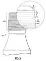
- FIG. 3shows a femoral stem of one example of the present invention in detail
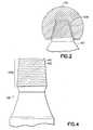
- FIG. 4shows a femoral stem of another example of the present invention in detail
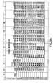
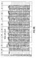
- FIGS. 5A and 5Bshow a table with example surface geometry characterizations relating to the present invention
- FIGS. 6 and 7show ridge face profiles according to other examples of the present invention.
- FIGS. 8A and 8Bshow varied pitch and depth according to other examples of the present invention.
- Prosthetic Device 101may include a first component attached to a second component. More particularly, in one example (which example is intended to be illustrative and not restrictive), the first component may comprise Femoral Head 103 and the second component may comprise Femoral Stem 105 . In another example Femoral Head 103 may comprise a ceramic material and Femoral Stem 105 may comprise a metallic material (e.g., Cobalt Chromium).
- Femoral Head 103may include a female recess (defined by Recess Wall 103 A) for receiving Male Extension 107 (e.g., “trunnion”) associated with Femoral Stem 105 (see FIG. 2 ).
- Male Extension 107e.g., “trunnion”
- the female recessmay taper from wider to narrower in a direction moving from an exterior surface of Femoral Head 103 towards an interior of Femoral Head 103 and at least part of an exterior surface of Male Extension 107 may taper from wider to narrower in a direction moving towards an end of Male Extension 107 .
- the female recessmay be configured to receive at least part of the exterior surface of Male Extension 107 such that, when the female recess receives Male Extension 107 , Male Extension 107 and the female recess are mated together via an interference fit (i.e., an interference fit between at least part of the exterior surface of Male Extension 107 and at least part of Recess Wall 103 A).
- an interference fiti.e., an interference fit between at least part of the exterior surface of Male Extension 107 and at least part of Recess Wall 103 A.
- Femoral Stem 105may include Male Extension 107 A having disposed on at least a part of its exterior surface a plurality of grooves and a plurality of ridges.
- Male Extension 107 Ahaving disposed on at least a part of its exterior surface a plurality of grooves and a plurality of ridges.
- details of these grooves and ridgesare shown in the circled detail portion of FIG. 3 (of note, only Groove 301 , Groove 303 and Ridge 305 are separately called out with numerical identifiers in this Fig.).
- Grooves 301 and 303may be disposed adjacent one another such that Ridge 305 is formed between Grooves 301 and 303 . Further, it is seen that Ridge 305 has a first ridge face formed by Groove 301 and that Ridge 305 has a second ridge face formed by Groove 303 . Moreover, it is seen that the first ridge face and the second ridge face of Ridge 305 meet at a ridge apex.
- the measurement identified by the letter “d”may specify the depth of the grooves (for example, as measured from a ridge apex to a bottom of a groove), that the measurement identified by the letter “p” may specify the pitch of the groove/ridge topography (for example, as measured from one ridge apex to the next) and that the measurement identified by the letter “r” may specify the radius of the grooves (for example, as measured to the bottom of a groove).
- FIG. 4depicts a single helical thread on Male Extension 107 B. That is, Groove 401 and Ridge 403 wrap around and around Male Extension 107 B in an essentially continuous manner.
- the surface profile of Male Extension 107 Bmay otherwise be similar to that of Male Extension 107 A of FIG. 3 (e.g., with regard to the “d”, “p” and “r” dimensions and with regard to the fact that Ridge 403 has a ridge apex blending essentially directly into the groove).
- one or more ridgesmay be configured to deform against Recess Wall 103 A of the female recess. More particularly, in one example (which example is intended to be illustrative and not restrictive), one or more ridge apexes may be configured to deform against Recess Wall 103 A of the female recess. In this regard, it is noted that the substantial amount of deformation provided by the ridge apexes may provide for a strong attachment with advantageous stress/strain characteristics.
- FIGS. 5A and 5Bshowing, respectively, the left-hand portion and the right-hand portion of a table depicting example radius, pitch and depth values which may be applied to the embodiments of FIGS. 3 and 4 (of course, the examples of this table are intended to be illustrative and not restrictive).
- the pitch values of this tablei.e., the variables along column “B” refer to the pitch identification “p” in FIGS. 3 and 4
- the radius values of this tablei.e., the variables along row “ 6 ” refer to the radius identification “r” in FIGS.
- radius and pitchmay result in geometries having various burst strengths when applied, for example, to a metallic femoral stem component which is inserted into a ceramic femoral head component.
- burst strengthmay be increased (up to a point) by increasing depth/decreasing pitch.
- r, p and/or d valuesmay be chosen for any particular implementation in order to meet any desired criteria (e.g., minimum burst strength).
- r, p and/or d valuesmay be chosen to meet a current FDA requirement of >46 kN with Cobalt Chromium alloys (which are relatively rigid and hard compared to Titanium Aluminum Vanadium, for example).
- FIGS. 6 and 7two additional ridge face profiles (in addition to the profiles already shown in the proceeding Figs.) are shown.
- FIG. 6shows a substantially flat ridge face profile in which Ridge 601 comprises First Ridge Face 601 a and Second Ridge Face 601 b meeting at the apex of Ridge 601 .
- First Ridge Face 601 a and Second Ridge Face 601 bmay have any desired angle “ ⁇ ”, any desired spacing “p” and any desired depth “d”.
- Ridge 601may “rise up” from the underlying surface rather than be formed by grooves “cut into” the surface.
- only Groove 601 , First Ridge Face 601 a and Second Ridge Face 601 bare separately called out with numerical identifiers in this Fig. (the other ridges/ridge faces are not separately called out with numerical identifiers).
- FIG. 7shows a substantially flat ridge face profile in which Ridge 701 comprises First Ridge Face 701 a and Second Ridge Face 701 b meeting at the apex of Ridge 701 .
- First Ridge Face 701 a and Second Ridge Face 701 bmay have any desired angle “ ⁇ ”, any desired spacing “p” and any desired depth “d”.
- Ridge 701may be formed by Grooves 702 a and 702 b in a manner similar to that shown in FIGS. 3 and 4 , for example (rather than “rising up” from the underlying surface as shown in FIG. 6 ).
- the pitch “p”may vary (e.g., the pitch “p” may vary over the taper length of the male extension). This varied pitch may provide differing magnitudes of contact stresses to different parts of the male extension and/or the female recess/femoral head.
- the depth “d”may vary (e.g., the depth “d” may vary over the taper length of the male extension). This varied depth may likewise provide differing magnitudes of contact stresses to different parts of the male extension and/or the female recess/femoral head. Of course, either or both of the pitch and/or depth may be varied as desired.
- any element described hereinmay be provided in any desired size (e.g., any element described herein may be provided in any desired custom size or any element described herein may be provided in any desired size selected from a “family” of sizes, such as small, medium, large).
- one or more of the ridge facesmay be flat and/or curved convexly and/or curved concavely.
- the male extensionmay take any desired shape (rather than being in the form of an essentially circular truncated cone as shown in the figures).
- the female recessmay take any desired shape (rather than being in the form of an essentially circular truncated cone as shown in the figures).
- the recess wallmay have any desired topography (rather than being flat as shown in the figures).
- the taper angle of the femoral head and/or femoral stemmay be any desired taper angle (e.g., a nominal 12 / 14 taper angle).
- any component of the prosthesis adapted to attach to and/or in bonemay include any desired surface treatment (e.g., a thread for screwing into bone, surface irregularities for aiding in fixation (e.g., protrusions, indentations), slots, sandblasting, knurling, etc).
- the present inventionmay provide a mechanism via which the stresses developed in the prosthesis (e.g., in the ceramic head) may be designed for any desired value (e.g., may be designed to meet loading levels mandated by the FDA).
- the present inventionmay provide a mechanism to accommodate inaccuracies in the interface between components of the prosthesis (for example, between a femoral stem component which is inserted into a femoral head component).
- one or more of the components of the prosthesismay include any of the following materials: (a) any biocompatible material (which biocompatible material may be treated to permit bone ingrowth or prohibit bone ingrowth—depending upon the desire of the surgeon); (b) a plastic; (c) a fiber; (d) a polymer; (e) a pure metal; (f) a metal alloy (e.g., Cobalt Chromium, Titanium Aluminum Vanadium); (g) a ceramic; (h) any combination thereof.
- variable pitch and depth parameterse.g., over at least a part of the length of the male extension
- any groove and/or ridge parametersmay be varied as desired.
- any steps described hereinmay be carried out in any desired order.
Landscapes
- Health & Medical Sciences (AREA)
- Orthopedic Medicine & Surgery (AREA)
- Cardiology (AREA)
- Oral & Maxillofacial Surgery (AREA)
- Transplantation (AREA)
- Engineering & Computer Science (AREA)
- Biomedical Technology (AREA)
- Heart & Thoracic Surgery (AREA)
- Vascular Medicine (AREA)
- Life Sciences & Earth Sciences (AREA)
- Animal Behavior & Ethology (AREA)
- General Health & Medical Sciences (AREA)
- Public Health (AREA)
- Veterinary Medicine (AREA)
- Prostheses (AREA)
- Mechanical Control Devices (AREA)
Abstract
Description
- In one embodiment of the present invention a prosthesis including a mechanism for attaching a first component to a second component is provided.
- In one example (which example is intended to be illustrative and not restrictive), the first component may be a femoral head component and the second component may be a femoral stem component.
- In another example (which example is intended to be illustrative and not restrictive), the femoral head component may comprise a ceramic material and the femoral stem component may comprise a metallic material (e.g., any desired orthopedic alloy, such as Cobalt Chromium).
- For the purposes of describing and claiming the present invention, the term “interference fit” is intended to refer to physical contact between two or more components.
- Further, for the purposes of describing and claiming the present invention, the term “ridge face” is intended to refer to a surface forming a side portion of a ridge.
- Further still, for the purposes of describing and claiming the present invention, the term “ridge apex” is intended to refer to the tip of a ridge where the “ridge faces” meet one another. To give a number of examples of what is meant by “ridge apex” (which examples are intended to be illustrative and not restrictive), reference is made to
FIG. 3 showing the apex of Ridge305,FIG. 6 showing the apex of Ridge601 andFIG. 7 showing the apex of Ridge701. - Various systems for connecting components of a prosthesis together have been proposed.
- See, for example, Richter, H. G., Willmann, G., Wimmer, M., and Osthues, F. G., “Influence of the Ball/Stem-Interface on the Load Bearing Capability of Modular Total Hip Endoprosthesis,” Modularity of Orthopedic Implants, ASTM STP 1301 Donald E. Marlowe, Jack E. Parr, and Michael B. Mayor, Eds., American Society for Testing and materials, 1997 (hereinafter “Richter et al.”).
- More particularly, Richter et al. discusses a study in which “the surface structure of metal tapers is varied systematically in order to evaluate the influence of groove depth and pitch on the resistance to static load.”
- Additional examples of systems for connecting components of a prosthesis together include the systems described in the following U.S. Patents:
- U.S. Pat. No. 4,225,981 issued Oct. 7, 1980 to Zeibig relates to an endoprosthesis with a metal-ceramic union. More particularly, this patent relates to a bone joint endoprosthesis in which the spigot of the metal shank is externally threaded to mate with a thread inside the ceramic head of the prosthesis; the thread on the spigot has greater depth in the radial direction, with flat sides, and the depth of the thread in the head is more shallow.
- U.S. Pat. No. 5,584,629 issued Dec. 17, 1996 to Bailey et al. relates to a connector for medical implant. More particularly, this patent relates to a connection for components in a medical implant assembly which utilizes a tapered mating surface on each component with cylindrical splines and flutes formed on each mating surface such that the surfaces are complementary to the extent that the splines of one surface are received in the flutes of the adjacent surface. The patent indicates that each surface is continuous with no discontinuity which would act as a stress raiser or enhance concentration of stress in one locale. The complementary surfaces are urged into registry by a screw connection coaxially through the surfaces.
- U.S. Pat. No. 5,865,850 issued Feb. 2, 1999 to Matthews relates to a coated load bearing surface for a prosthetic joint. More particularly, this patent relates to a prosthetic hip joint including a ceramic hip head having a bore which defines a surface, wherein the bore surface has a layer of malleable material disposed on at least a portion thereof. The surface of the bore includes surface imperfections in the form of peaks and valleys. The prosthetic hip joint can also include a femoral component having a trunnion with a tapered surface adapted for friction fit insertion into the bore of the hip head. The patent indicates that the layer of material, such as pure titanium, distributes a load on the joint reducing localized stress points produced by opposing asperity peaks in the load-bearing surfaces of the bore and trunnion.
FIG. 1 shows a prosthetic device including a femoral head and a femoral stem attached according to an embodiment of the present invention;FIG. 2 shows a cross section of the femoral stem ofFIG. 1 received by the femoral head ofFIG. 1 ;FIG. 3 shows a femoral stem of one example of the present invention in detail;FIG. 4 shows a femoral stem of another example of the present invention in detail;FIGS. 5A and 5B show a table with example surface geometry characterizations relating to the present invention;FIGS. 6 and 7 show ridge face profiles according to other examples of the present invention; andFIGS. 8A and 8B show varied pitch and depth according to other examples of the present invention.- Among those benefits and improvements that have been disclosed, other objects and advantages of this invention will become apparent from the following description taken in conjunction with the accompanying figures. The figures constitute a part of this specification and include illustrative embodiments of the present invention and illustrate various objects and features thereof.
- Detailed embodiments of the present invention are disclosed herein; however, it is to be understood that the disclosed embodiments are merely illustrative of the invention that may be embodied in various forms. In addition, each of the examples given in connection with the various embodiments of the invention are intended to be illustrative, and not restrictive. Further, the figures are not necessarily to scale, some features may be exaggerated to show details of particular components. Therefore, specific structural and functional details disclosed herein are not to be interpreted as limiting, but merely as a representative basis for teaching one skilled in the art to variously employ the present invention.
- Referring now to
FIGS. 1 and 2 , one embodiment of the present invention is shown. As seen in these Figs.,Prosthetic Device 101 may include a first component attached to a second component. More particularly, in one example (which example is intended to be illustrative and not restrictive), the first component may compriseFemoral Head 103 and the second component may compriseFemoral Stem 105. In another exampleFemoral Head 103 may comprise a ceramic material andFemoral Stem 105 may comprise a metallic material (e.g., Cobalt Chromium). - Further,
Femoral Head 103 may include a female recess (defined by Recess Wall103A) for receiving Male Extension107 (e.g., “trunnion”) associated with Femoral Stem105 (seeFIG. 2 ). - In addition, the female recess may taper from wider to narrower in a direction moving from an exterior surface of
Femoral Head 103 towards an interior ofFemoral Head 103 and at least part of an exterior surface ofMale Extension 107 may taper from wider to narrower in a direction moving towards an end ofMale Extension 107. - Moreover, the female recess may be configured to receive at least part of the exterior surface of
Male Extension 107 such that, when the female recess receivesMale Extension 107,Male Extension 107 and the female recess are mated together via an interference fit (i.e., an interference fit between at least part of the exterior surface ofMale Extension 107 and at least part of RecessWall 103A). - Referring now to
FIG. 3 , certain details of FemoralStem 105 in connection with one example of the present invention (which example is intended to be illustrative and not restrictive) are shown. More particularly, it is seen thatFemoral Stem 105 may includeMale Extension 107A having disposed on at least a part of its exterior surface a plurality of grooves and a plurality of ridges. In this regard, details of these grooves and ridges are shown in the circled detail portion ofFIG. 3 (of note, onlyGroove 301, Groove303 and Ridge305 are separately called out with numerical identifiers in this Fig.). - In any case, it is seen that Grooves301 and303 may be disposed adjacent one another such that Ridge305 is formed between
Grooves - Still referring to
FIG. 3 , it is seen that the measurement identified by the letter “d” may specify the depth of the grooves (for example, as measured from a ridge apex to a bottom of a groove), that the measurement identified by the letter “p” may specify the pitch of the groove/ridge topography (for example, as measured from one ridge apex to the next) and that the measurement identified by the letter “r” may specify the radius of the grooves (for example, as measured to the bottom of a groove). - Of note, the ridges and grooves of this
FIG. 3 may be essentially parallel to one another and may form discrete concentric elements alongMale Extension 107A. In contrast, reference is now made to the example ofFIG. 4 (which example is intended to be illustrative and not restrictive). More particularly, thisFIG. 4 depicts a single helical thread on Male Extension107B. That is, Groove401 and Ridge403 wrap around and aroundMale Extension 107B in an essentially continuous manner. Of note, the surface profile ofMale Extension 107B may otherwise be similar to that ofMale Extension 107A ofFIG. 3 (e.g., with regard to the “d”, “p” and “r” dimensions and with regard to the fact that Ridge403 has a ridge apex blending essentially directly into the groove). - Referring now to the attachment of
Femoral Stem 105 to Femoral Head103, it is noted that one or more ridges may be configured to deform against RecessWall 103A of the female recess. More particularly, in one example (which example is intended to be illustrative and not restrictive), one or more ridge apexes may be configured to deform against RecessWall 103A of the female recess. In this regard, it is noted that the substantial amount of deformation provided by the ridge apexes may provide for a strong attachment with advantageous stress/strain characteristics. - Reference will now be made to
FIGS. 5A and 5B showing, respectively, the left-hand portion and the right-hand portion of a table depicting example radius, pitch and depth values which may be applied to the embodiments ofFIGS. 3 and 4 (of course, the examples of this table are intended to be illustrative and not restrictive). Of note, the pitch values of this table (i.e., the variables along column “B”) refer to the pitch identification “p” inFIGS. 3 and 4 , the radius values of this table (i.e., the variables along row “6”) refer to the radius identification “r” inFIGS. 3 and 4 and the depth values of this table (i.e., the result of carrying out the computations using the various pitch and radius values) refer to the depth identification “d” inFIGS. 3 and 4 (the values shown in this table are in inches). Of further note, the depth values in this table are the result of the following computation:
d=r−√{square root over (r2−(p/2)2)} - Still referring to
FIGS. 5A and 5B , it is noted that certain combinations of radius and pitch may be physically impossible to realize (see, e.g., column “C”, rows10-21; column “D”, rows14-21; and column “E”, rows18-21) and certain combinations of radius and pitch may be very difficult to manufacture (see, e.g., column “C”,row 9; column “D”,row 13; column “E”,row 17; and column “F”, row21). - Moreover, it is noted that various combinations of radius and pitch may result in geometries having various burst strengths when applied, for example, to a metallic femoral stem component which is inserted into a ceramic femoral head component.
- More particularly, tests have revealed, for example, that a combination of r=0.008 and p=0.008 (resulting in d=1.072E−3) has a burst strength of 47 kN when a Cobalt Chromium femoral stem component is inserted into a ceramic femoral head component; that a combination of r=0.015 and p=0.010 (resulting in d=8.579E−4) has a burst strength of 43 kN when a Cobalt Chromium femoral stem component is inserted into a ceramic femoral head component; and that a combination of r=0.03 and p=0.016 (resulting in d=1.086E−3) has a burst strength of 38 kN when a Cobalt Chromium femoral stem component is inserted into a ceramic femoral head component.
- In addition, it is noted that in general burst strength may be increased (up to a point) by increasing depth/decreasing pitch. In this regard, it is believed, for example, that the combinations of r=0.002 and p=0.002 to 0.003; r=0.004 and p=0.002 to 0.007; r=0.006 and p=0.002 to 0.011; r=0.008 and p=0.002 to 0.015; r=0.010 and p=0.002 to 0.016; r=0.012 and p=0.002 to 0.016; r=0.014 and p=0.002 to 0.016; and r=0.015 and p=0.012 to 0.016 would likely have a burst strength greater than 47 kN.
- Finally, it is noted that specific r, p and/or d values may be chosen for any particular implementation in order to meet any desired criteria (e.g., minimum burst strength). For example (which example is intended to be illustrative and not restrictive), r, p and/or d values may be chosen to meet a current FDA requirement of >46 kN with Cobalt Chromium alloys (which are relatively rigid and hard compared to Titanium Aluminum Vanadium, for example).
- Referring now to
FIGS. 6 and 7 , two additional ridge face profiles (in addition to the profiles already shown in the proceeding Figs.) are shown. - More particularly,
FIG. 6 shows a substantially flat ridge face profile in whichRidge 601 comprisesFirst Ridge Face 601aandSecond Ridge Face 601bmeeting at the apex ofRidge 601. Of note,First Ridge Face 601aandSecond Ridge Face 601bmay have any desired angle “θ”, any desired spacing “p” and any desired depth “d”. Of further note,Ridge 601 may “rise up” from the underlying surface rather than be formed by grooves “cut into” the surface. Of still further note, onlyGroove 601,First Ridge Face 601aandSecond Ridge Face 601bare separately called out with numerical identifiers in this Fig. (the other ridges/ridge faces are not separately called out with numerical identifiers). - Further,
FIG. 7 shows a substantially flat ridge face profile in whichRidge 701 comprises First Ridge Face701aand Second Ridge Face701bmeeting at the apex ofRidge 701. Of note, First Ridge Face701aand Second Ridge Face701bmay have any desired angle “θ”, any desired spacing “p” and any desired depth “d”. Of further note,Ridge 701 may be formed byGrooves FIGS. 3 and 4 , for example (rather than “rising up” from the underlying surface as shown inFIG. 6 ). Of still further note, onlyRidge 701, First Ridge Face701a,Second Ridge Face701bandGrooves - Referring now to
FIG. 8A , it is seen that the pitch “p” may vary (e.g., the pitch “p” may vary over the taper length of the male extension). This varied pitch may provide differing magnitudes of contact stresses to different parts of the male extension and/or the female recess/femoral head. - Referring now to
FIG. 8B , it is seen that the depth “d” may vary (e.g., the depth “d” may vary over the taper length of the male extension). This varied depth may likewise provide differing magnitudes of contact stresses to different parts of the male extension and/or the female recess/femoral head. Of course, either or both of the pitch and/or depth may be varied as desired. - While a number of embodiments of the present invention have been described, it is understood that these embodiments are illustrative only, and not restrictive, and that many modifications may become apparent to those of ordinary skill in the art. For example, the present invention may be applied to a prosthesis for use anywhere in or on the body. Further, any element described herein may be provided in any desired size (e.g., any element described herein may be provided in any desired custom size or any element described herein may be provided in any desired size selected from a “family” of sizes, such as small, medium, large). Further still, one or more of the ridge faces may be flat and/or curved convexly and/or curved concavely. Further still, the male extension may take any desired shape (rather than being in the form of an essentially circular truncated cone as shown in the figures). Further still, the female recess may take any desired shape (rather than being in the form of an essentially circular truncated cone as shown in the figures). Further still, the recess wall may have any desired topography (rather than being flat as shown in the figures). Further still, the taper angle of the femoral head and/or femoral stem may be any desired taper angle (e.g., a nominal12/14 taper angle). Further still, any component of the prosthesis adapted to attach to and/or in bone (e.g., a femoral stem) may include any desired surface treatment (e.g., a thread for screwing into bone, surface irregularities for aiding in fixation (e.g., protrusions, indentations), slots, sandblasting, knurling, etc). Further still, the present invention may provide a mechanism via which the stresses developed in the prosthesis (e.g., in the ceramic head) may be designed for any desired value (e.g., may be designed to meet loading levels mandated by the FDA). Further still, the present invention may provide a mechanism to accommodate inaccuracies in the interface between components of the prosthesis (for example, between a femoral stem component which is inserted into a femoral head component). Further still, one or more of the components of the prosthesis may include any of the following materials: (a) any biocompatible material (which biocompatible material may be treated to permit bone ingrowth or prohibit bone ingrowth—depending upon the desire of the surgeon); (b) a plastic; (c) a fiber; (d) a polymer; (e) a pure metal; (f) a metal alloy (e.g., Cobalt Chromium, Titanium Aluminum Vanadium); (g) a ceramic; (h) any combination thereof. Further still, while variable pitch and depth parameters (e.g., over at least a part of the length of the male extension) have been discussed, any groove and/or ridge parameters may be varied as desired. Further still, any steps described herein may be carried out in any desired order.
Claims (57)
Priority Applications (4)
| Application Number | Priority Date | Filing Date | Title |
|---|---|---|---|
| US11/042,367US7220283B2 (en) | 2005-01-24 | 2005-01-24 | Prosthesis including a mechanism for attaching a first component to a second component |
| EP06719030AEP1841384A4 (en) | 2005-01-24 | 2006-01-20 | PROSTHESIS WITH MECHANISM FOR FIXING A FIRST COMPONENT TO A SECOND COMPONENT |
| PCT/US2006/002052WO2006081142A2 (en) | 2005-01-24 | 2006-01-20 | Prosthesis including a mechanism for attaching a first component to a second component |
| US11/751,428US7955396B2 (en) | 2005-01-24 | 2007-05-21 | Prosthesis including a mechanism for attaching a first component to a second component |
Applications Claiming Priority (1)
| Application Number | Priority Date | Filing Date | Title |
|---|---|---|---|
| US11/042,367US7220283B2 (en) | 2005-01-24 | 2005-01-24 | Prosthesis including a mechanism for attaching a first component to a second component |
Related Child Applications (1)
| Application Number | Title | Priority Date | Filing Date |
|---|---|---|---|
| US11/751,428DivisionUS7955396B2 (en) | 2005-01-24 | 2007-05-21 | Prosthesis including a mechanism for attaching a first component to a second component |
Publications (2)
| Publication Number | Publication Date |
|---|---|
| US20060167557A1true US20060167557A1 (en) | 2006-07-27 |
| US7220283B2 US7220283B2 (en) | 2007-05-22 |
Family
ID=36697956
Family Applications (2)
| Application Number | Title | Priority Date | Filing Date |
|---|---|---|---|
| US11/042,367Expired - LifetimeUS7220283B2 (en) | 2005-01-24 | 2005-01-24 | Prosthesis including a mechanism for attaching a first component to a second component |
| US11/751,428Expired - Fee RelatedUS7955396B2 (en) | 2005-01-24 | 2007-05-21 | Prosthesis including a mechanism for attaching a first component to a second component |
Family Applications After (1)
| Application Number | Title | Priority Date | Filing Date |
|---|---|---|---|
| US11/751,428Expired - Fee RelatedUS7955396B2 (en) | 2005-01-24 | 2007-05-21 | Prosthesis including a mechanism for attaching a first component to a second component |
Country Status (3)
| Country | Link |
|---|---|
| US (2) | US7220283B2 (en) |
| EP (1) | EP1841384A4 (en) |
| WO (1) | WO2006081142A2 (en) |
Cited By (20)
| Publication number | Priority date | Publication date | Assignee | Title |
|---|---|---|---|---|
| US7445639B2 (en) | 2001-02-23 | 2008-11-04 | Biomet Manufacturing Corp. | Knee joint prosthesis |
| US7497874B1 (en) | 2001-02-23 | 2009-03-03 | Biomet Manufacturing Corp. | Knee joint prosthesis |
| US8157869B2 (en) | 2007-01-10 | 2012-04-17 | Biomet Manufacturing Corp. | Knee joint prosthesis system and method for implantation |
| US8163028B2 (en) | 2007-01-10 | 2012-04-24 | Biomet Manufacturing Corp. | Knee joint prosthesis system and method for implantation |
| US8187280B2 (en) | 2007-10-10 | 2012-05-29 | Biomet Manufacturing Corp. | Knee joint prosthesis system and method for implantation |
| ITMI20110122A1 (en)* | 2011-02-01 | 2012-08-02 | Ala Ortho S R L | FEMORAL STEM FOR PROSTHESIS OF THE HIP. |
| US20120239160A1 (en)* | 2009-05-07 | 2012-09-20 | Smith & Nephew, Inc. | Modular trial heads for a prosthetic |
| US8328873B2 (en) | 2007-01-10 | 2012-12-11 | Biomet Manufacturing Corp. | Knee joint prosthesis system and method for implantation |
| US20130108986A1 (en)* | 2010-02-23 | 2013-05-02 | Seung Young Lee | Abutment for implant |
| US20130204390A1 (en)* | 2006-12-07 | 2013-08-08 | Ihip Surgical, Llc | Method and apparatus for attachment in a modular hip replacement or fracture fixation device |
| US8562616B2 (en) | 2007-10-10 | 2013-10-22 | Biomet Manufacturing, Llc | Knee joint prosthesis system and method for implantation |
| WO2014070616A1 (en)* | 2012-10-30 | 2014-05-08 | Meulink Steven L | Orthopedic connections |
| US8795381B2 (en) | 2006-12-07 | 2014-08-05 | Ihip Surgical, Llc | Methods and systems for hip replacement |
| US20150342745A1 (en)* | 2014-06-02 | 2015-12-03 | Stryker European Holdings I, Llc | Metacarpal rod anchor for a trapezometacarpal prosthesis |
| US9237949B2 (en) | 2006-12-07 | 2016-01-19 | Ihip Surgical, Llc | Method and apparatus for hip replacement |
| US20160051367A1 (en)* | 2012-07-05 | 2016-02-25 | LIMACORPORATE S.p.A | Humeral implant for a shoulder prosthesis |
| US9615927B2 (en)* | 2015-03-31 | 2017-04-11 | Depuy Ireland Unlimited Company | Orthopaedic surgical instrument system and method for protecting a femoral stem taper |
| USD858772S1 (en)* | 2017-11-15 | 2019-09-03 | Joint Innovation Technology, Llc | Ball and stem component |
| US11344437B2 (en)* | 2017-10-03 | 2022-05-31 | Depuy Ireland Unlimited Company | Trial neck apparatus and method |
| US11826267B2 (en) | 2017-04-12 | 2023-11-28 | Depuy Ireland Unlimited Company | Femoral trialling kit and assembly |
Families Citing this family (10)
| Publication number | Priority date | Publication date | Assignee | Title |
|---|---|---|---|---|
| US6746483B1 (en) | 2000-03-16 | 2004-06-08 | Smith & Nephew, Inc. | Sheaths for implantable fixation devices |
| US7220283B2 (en)* | 2005-01-24 | 2007-05-22 | Exactech, Inc. | Prosthesis including a mechanism for attaching a first component to a second component |
| US8560047B2 (en) | 2006-06-16 | 2013-10-15 | Board Of Regents Of The University Of Nebraska | Method and apparatus for computer aided surgery |
| US8795194B2 (en) | 2007-03-30 | 2014-08-05 | Smith & Nephew, Inc. | Tissue harvesting |
| DE102008047060B4 (en)* | 2008-09-12 | 2011-05-26 | Tracto-Technik Gmbh & Co. Kg | threaded connection |
| CN103764061B (en) | 2011-06-27 | 2017-03-08 | 内布拉斯加大学评议会 | On Tool Tracking System and Computer Assisted Surgery Method |
| US11911117B2 (en) | 2011-06-27 | 2024-02-27 | Board Of Regents Of The University Of Nebraska | On-board tool tracking system and methods of computer assisted surgery |
| US9498231B2 (en) | 2011-06-27 | 2016-11-22 | Board Of Regents Of The University Of Nebraska | On-board tool tracking system and methods of computer assisted surgery |
| US10105149B2 (en) | 2013-03-15 | 2018-10-23 | Board Of Regents Of The University Of Nebraska | On-board tool tracking system and methods of computer assisted surgery |
| TWI634881B (en)* | 2015-04-21 | 2018-09-11 | 寶楠生技股份有限公司 | Femoral stem with cushion |
Citations (25)
| Publication number | Priority date | Publication date | Assignee | Title |
|---|---|---|---|---|
| US1817808A (en)* | 1930-11-20 | 1931-08-04 | Spang Chalfant & Company Inc | Method of making tight threaded joints |
| US2367213A (en)* | 1943-03-26 | 1945-01-16 | Crown Cork & Seal Co | Self-locking threaded device |
| US3258284A (en)* | 1963-12-30 | 1966-06-28 | Phipps Orville | Drill bit and rod coupling |
| US3707107A (en)* | 1970-01-26 | 1972-12-26 | Hans Bieri | Screw connection for high loading |
| US3987499A (en)* | 1973-08-10 | 1976-10-26 | Sybron Corporation | Surgical implant and method for its production |
| US4012795A (en)* | 1974-10-29 | 1977-03-22 | Feldmuhle Anlagen- Und Produktionsgesellschaft Mit Beschrankter Haftung | Artificial head assembly for an articulated joint between two bones |
| US4040756A (en)* | 1976-03-05 | 1977-08-09 | Trw Canada Limited | Drill rod thread form |
| US4058856A (en)* | 1975-10-27 | 1977-11-22 | Sulzer Brothers Limited | Joint endoprosthesis |
| US4225981A (en)* | 1977-09-19 | 1980-10-07 | Rosenthal Technik Ag | Endo prothesis with a metal-ceramic union |
| US4528702A (en)* | 1982-10-15 | 1985-07-16 | Sulzer Brothers Limited | Joint endoprosthesis |
| US4921500A (en)* | 1989-02-28 | 1990-05-01 | Osteonics Corp. | Femoral head adaptor for interoperative assembly |
| US5015257A (en)* | 1989-03-20 | 1991-05-14 | Zimmer, Inc. | Prosthetic interpositional device/coupler |
| US5362311A (en)* | 1990-01-05 | 1994-11-08 | Kyocera Corporation | Artificial hip joint |
| US5584629A (en)* | 1995-05-30 | 1996-12-17 | Crystal Medical Technology, A Division Of Folsom Metal Products, Inc. | Connector for medical implant |
| US5865850A (en)* | 1997-03-10 | 1999-02-02 | Johnson & Johnson Professional, Inc. | Coated load bearing surface for a prosthetic joint |
| US6096084A (en)* | 1998-09-04 | 2000-08-01 | Biopro, Inc. | Modular ball and socket joint preferably with a ceramic head ball |
| US6336941B1 (en)* | 1998-08-14 | 2002-01-08 | G. V. Subba Rao | Modular hip implant with shock absorption system |
| US20020031675A1 (en)* | 2000-04-27 | 2002-03-14 | Bernard Cales | Partially stabilized zirconia biocomponent having high resistance to low temperature degradation and a method of preparing same |
| US6451057B1 (en)* | 2001-10-29 | 2002-09-17 | Chen Po-Quang | Spinal plate element adjusting device having a threaded engagement |
| US6591475B2 (en)* | 1996-02-23 | 2003-07-15 | Hitachi, Ltd. | Method for fixing a taper implant to a receiving member |
| US6607560B1 (en)* | 1999-02-04 | 2003-08-19 | Ceramtec Ag Innovative Ceramic Engineering | Press fit connection between prosthetic components of joint prostheses |
| US20040015238A1 (en)* | 2000-03-02 | 2004-01-22 | Buehler Knute C. | Shrouds for implants |
| US20040063069A1 (en)* | 2002-09-30 | 2004-04-01 | Lombardi Steven B. | External locking dental implant system |
| US6840770B2 (en)* | 2001-12-28 | 2005-01-11 | Mcdevitt Dennis | Expandable polymer dental implant and method of use |
| US6863530B2 (en)* | 2001-12-28 | 2005-03-08 | Incumed, Inc. | Expandable polymer dental implant and method of use |
Family Cites Families (15)
| Publication number | Priority date | Publication date | Assignee | Title |
|---|---|---|---|---|
| US3921353A (en)* | 1972-02-04 | 1975-11-25 | Howlett Machine Works | Tendon anchorage assembly and bore mounting apparatus therefor |
| EP0024442A1 (en)* | 1979-08-22 | 1981-03-11 | Rosenthal Technik AG | Composite endoprosthesis consisting of a metallic body and a ceramic joint |
| US5030234A (en)* | 1989-12-12 | 1991-07-09 | Pappas Michael J | Prosthetic device with modular stem |
| US20040015236A1 (en)* | 1991-11-18 | 2004-01-22 | Sarfarazi Faezeh M. | Sarfarazi elliptical accommodative intraocular lens for small incision surgery |
| US5169122A (en)* | 1991-12-02 | 1992-12-08 | Sunderland John W | Compression boiler drain |
| DE4405447B4 (en)* | 1994-02-21 | 2006-03-09 | Cerasiv Gmbh Innovatives Keramik-Engineering | hip prosthesis |
| US5852962A (en)* | 1997-04-29 | 1998-12-29 | Fraering, Jr.; Camille M. | Apparatus for reconditioning threaded tubular connection seal shoulders |
| JP3857784B2 (en)* | 1997-07-17 | 2006-12-13 | 日本特殊陶業株式会社 | Ceramic head bones and bone head system for artificial joints |
| DE19813074A1 (en)* | 1998-03-25 | 1999-09-30 | Ceram Tec Ag Innovative Cerami | Clamp-fit connection between prosthetic components of joint prostheses |
| US7220283B2 (en) | 2005-01-24 | 2007-05-22 | Exactech, Inc. | Prosthesis including a mechanism for attaching a first component to a second component |
| US8048167B2 (en)* | 2005-08-30 | 2011-11-01 | Depuy Products, Inc. | Orthopaedic implant kit, orthopaedic surgery kit and associated method |
| US20070162147A1 (en)* | 2005-12-21 | 2007-07-12 | Lewis Paul P P | Orthopaedic joint assembly with rigidly locked fastener, kit and associated method |
| US20070198094A1 (en)* | 2006-02-17 | 2007-08-23 | Biomet Manufacturing Corp. | Adaptor prosthesis kit |
| FR2909542A1 (en)* | 2006-12-06 | 2008-06-13 | Hi Walk Soc Civ Ile | Spherical shaped ceramic recovery head for modular hip prosthesis, has tapered cavity covered with thin layer made of biocompatible material, where thickness of material is increased from opening of tapered cavity to bottom of head |
| US8216312B2 (en)* | 2007-05-31 | 2012-07-10 | Zimmer Spine, Inc. | Spinal interbody system and method |
- 2005
- 2005-01-24USUS11/042,367patent/US7220283B2/ennot_activeExpired - Lifetime
- 2006
- 2006-01-20EPEP06719030Apatent/EP1841384A4/ennot_activeWithdrawn
- 2006-01-20WOPCT/US2006/002052patent/WO2006081142A2/enactiveApplication Filing
- 2007
- 2007-05-21USUS11/751,428patent/US7955396B2/ennot_activeExpired - Fee Related
Patent Citations (26)
| Publication number | Priority date | Publication date | Assignee | Title |
|---|---|---|---|---|
| US1817808A (en)* | 1930-11-20 | 1931-08-04 | Spang Chalfant & Company Inc | Method of making tight threaded joints |
| US2367213A (en)* | 1943-03-26 | 1945-01-16 | Crown Cork & Seal Co | Self-locking threaded device |
| US3258284A (en)* | 1963-12-30 | 1966-06-28 | Phipps Orville | Drill bit and rod coupling |
| US3707107A (en)* | 1970-01-26 | 1972-12-26 | Hans Bieri | Screw connection for high loading |
| US3987499A (en)* | 1973-08-10 | 1976-10-26 | Sybron Corporation | Surgical implant and method for its production |
| US4012795A (en)* | 1974-10-29 | 1977-03-22 | Feldmuhle Anlagen- Und Produktionsgesellschaft Mit Beschrankter Haftung | Artificial head assembly for an articulated joint between two bones |
| US4058856A (en)* | 1975-10-27 | 1977-11-22 | Sulzer Brothers Limited | Joint endoprosthesis |
| US4040756A (en)* | 1976-03-05 | 1977-08-09 | Trw Canada Limited | Drill rod thread form |
| US4225981A (en)* | 1977-09-19 | 1980-10-07 | Rosenthal Technik Ag | Endo prothesis with a metal-ceramic union |
| US4528702A (en)* | 1982-10-15 | 1985-07-16 | Sulzer Brothers Limited | Joint endoprosthesis |
| US4921500A (en)* | 1989-02-28 | 1990-05-01 | Osteonics Corp. | Femoral head adaptor for interoperative assembly |
| US5015257A (en)* | 1989-03-20 | 1991-05-14 | Zimmer, Inc. | Prosthetic interpositional device/coupler |
| US5362311A (en)* | 1990-01-05 | 1994-11-08 | Kyocera Corporation | Artificial hip joint |
| US5584629A (en)* | 1995-05-30 | 1996-12-17 | Crystal Medical Technology, A Division Of Folsom Metal Products, Inc. | Connector for medical implant |
| US6591475B2 (en)* | 1996-02-23 | 2003-07-15 | Hitachi, Ltd. | Method for fixing a taper implant to a receiving member |
| US6609288B2 (en)* | 1996-02-23 | 2003-08-26 | Hitachi, Ltd. | Taper implant and a screw-fastening structure using a taper implant with female threads |
| US5865850A (en)* | 1997-03-10 | 1999-02-02 | Johnson & Johnson Professional, Inc. | Coated load bearing surface for a prosthetic joint |
| US6336941B1 (en)* | 1998-08-14 | 2002-01-08 | G. V. Subba Rao | Modular hip implant with shock absorption system |
| US6096084A (en)* | 1998-09-04 | 2000-08-01 | Biopro, Inc. | Modular ball and socket joint preferably with a ceramic head ball |
| US6607560B1 (en)* | 1999-02-04 | 2003-08-19 | Ceramtec Ag Innovative Ceramic Engineering | Press fit connection between prosthetic components of joint prostheses |
| US20040015238A1 (en)* | 2000-03-02 | 2004-01-22 | Buehler Knute C. | Shrouds for implants |
| US20020031675A1 (en)* | 2000-04-27 | 2002-03-14 | Bernard Cales | Partially stabilized zirconia biocomponent having high resistance to low temperature degradation and a method of preparing same |
| US6451057B1 (en)* | 2001-10-29 | 2002-09-17 | Chen Po-Quang | Spinal plate element adjusting device having a threaded engagement |
| US6840770B2 (en)* | 2001-12-28 | 2005-01-11 | Mcdevitt Dennis | Expandable polymer dental implant and method of use |
| US6863530B2 (en)* | 2001-12-28 | 2005-03-08 | Incumed, Inc. | Expandable polymer dental implant and method of use |
| US20040063069A1 (en)* | 2002-09-30 | 2004-04-01 | Lombardi Steven B. | External locking dental implant system |
Cited By (31)
| Publication number | Priority date | Publication date | Assignee | Title |
|---|---|---|---|---|
| US7445639B2 (en) | 2001-02-23 | 2008-11-04 | Biomet Manufacturing Corp. | Knee joint prosthesis |
| US7497874B1 (en) | 2001-02-23 | 2009-03-03 | Biomet Manufacturing Corp. | Knee joint prosthesis |
| US8795381B2 (en) | 2006-12-07 | 2014-08-05 | Ihip Surgical, Llc | Methods and systems for hip replacement |
| US8974540B2 (en)* | 2006-12-07 | 2015-03-10 | Ihip Surgical, Llc | Method and apparatus for attachment in a modular hip replacement or fracture fixation device |
| US20130204390A1 (en)* | 2006-12-07 | 2013-08-08 | Ihip Surgical, Llc | Method and apparatus for attachment in a modular hip replacement or fracture fixation device |
| US9237949B2 (en) | 2006-12-07 | 2016-01-19 | Ihip Surgical, Llc | Method and apparatus for hip replacement |
| US8163028B2 (en) | 2007-01-10 | 2012-04-24 | Biomet Manufacturing Corp. | Knee joint prosthesis system and method for implantation |
| US8328873B2 (en) | 2007-01-10 | 2012-12-11 | Biomet Manufacturing Corp. | Knee joint prosthesis system and method for implantation |
| US8480751B2 (en) | 2007-01-10 | 2013-07-09 | Biomet Manufacturing, Llc | Knee joint prosthesis system and method for implantation |
| US8936648B2 (en) | 2007-01-10 | 2015-01-20 | Biomet Manufacturing, Llc | Knee joint prosthesis system and method for implantation |
| US8157869B2 (en) | 2007-01-10 | 2012-04-17 | Biomet Manufacturing Corp. | Knee joint prosthesis system and method for implantation |
| US9763793B2 (en) | 2007-10-10 | 2017-09-19 | Biomet Manufacturing, Llc | Knee joint prosthesis system and method for implantation |
| US10736747B2 (en) | 2007-10-10 | 2020-08-11 | Biomet Manufacturing, Llc | Knee joint prosthesis system and method for implantation |
| US8187280B2 (en) | 2007-10-10 | 2012-05-29 | Biomet Manufacturing Corp. | Knee joint prosthesis system and method for implantation |
| US8562616B2 (en) | 2007-10-10 | 2013-10-22 | Biomet Manufacturing, Llc | Knee joint prosthesis system and method for implantation |
| US20120239160A1 (en)* | 2009-05-07 | 2012-09-20 | Smith & Nephew, Inc. | Modular trial heads for a prosthetic |
| US8840676B2 (en)* | 2009-05-07 | 2014-09-23 | Smith & Nephew, Inc. | Modular trial heads for a prosthetic |
| US20130108986A1 (en)* | 2010-02-23 | 2013-05-02 | Seung Young Lee | Abutment for implant |
| WO2012104115A1 (en)* | 2011-02-01 | 2012-08-09 | Ala Ortho S.R.L. | Femoral stem for hip prosthesis |
| ITMI20110122A1 (en)* | 2011-02-01 | 2012-08-02 | Ala Ortho S R L | FEMORAL STEM FOR PROSTHESIS OF THE HIP. |
| US20160051367A1 (en)* | 2012-07-05 | 2016-02-25 | LIMACORPORATE S.p.A | Humeral implant for a shoulder prosthesis |
| US9820859B2 (en)* | 2012-07-05 | 2017-11-21 | Limacorporate S.P.A. | Humeral implant for a shoulder prosthesis |
| US10136933B2 (en) | 2012-10-30 | 2018-11-27 | Zimmer, Inc. | Orthopedic connections |
| WO2014070616A1 (en)* | 2012-10-30 | 2014-05-08 | Meulink Steven L | Orthopedic connections |
| US9597192B2 (en)* | 2014-06-02 | 2017-03-21 | Stryker European Holdings I, Llc | Metacarpal rod anchor for a trapezometacarpal prosthesis |
| US20150342745A1 (en)* | 2014-06-02 | 2015-12-03 | Stryker European Holdings I, Llc | Metacarpal rod anchor for a trapezometacarpal prosthesis |
| US9615927B2 (en)* | 2015-03-31 | 2017-04-11 | Depuy Ireland Unlimited Company | Orthopaedic surgical instrument system and method for protecting a femoral stem taper |
| US10201428B2 (en) | 2015-03-31 | 2019-02-12 | Depuy Ireland Unlimited Company | Orthopaedic surgical instrument system and method for protecting a femoral stem taper |
| US11826267B2 (en) | 2017-04-12 | 2023-11-28 | Depuy Ireland Unlimited Company | Femoral trialling kit and assembly |
| US11344437B2 (en)* | 2017-10-03 | 2022-05-31 | Depuy Ireland Unlimited Company | Trial neck apparatus and method |
| USD858772S1 (en)* | 2017-11-15 | 2019-09-03 | Joint Innovation Technology, Llc | Ball and stem component |
Also Published As
| Publication number | Publication date |
|---|---|
| US7220283B2 (en) | 2007-05-22 |
| US20070255419A1 (en) | 2007-11-01 |
| US7955396B2 (en) | 2011-06-07 |
| WO2006081142A3 (en) | 2007-11-22 |
| WO2006081142A2 (en) | 2006-08-03 |
| EP1841384A4 (en) | 2012-07-25 |
| EP1841384A2 (en) | 2007-10-10 |
Similar Documents
| Publication | Publication Date | Title |
|---|---|---|
| US7955396B2 (en) | Prosthesis including a mechanism for attaching a first component to a second component | |
| AU631616B2 (en) | Prosthetic interpositional device/coupler | |
| US6319286B1 (en) | Modular hip prosthesis | |
| US4908034A (en) | Endoprosthetic bone joint components | |
| AU2002220859B2 (en) | An orthopaedic joint prosthesis | |
| US5549704A (en) | Universal joint prosthesis | |
| EP0781533B1 (en) | Joint prosthesis augmentation system | |
| US4058856A (en) | Joint endoprosthesis | |
| US5865850A (en) | Coated load bearing surface for a prosthetic joint | |
| EP0983754B1 (en) | Proximally hollow prosthesis | |
| DE102013227136B4 (en) | Coated hemiprosthetic implant | |
| EP1065998B1 (en) | Joint prosthesis with press fit connection between prosthetic components | |
| US20050234559A1 (en) | Modular hip prosthesis | |
| US5066304A (en) | Prosthetic interpositional device/coupler | |
| US6712857B1 (en) | Acetabular component of total hip replacement assembly | |
| WO2000074604A1 (en) | Acetabular component of total hip replacement assembly | |
| US10136933B2 (en) | Orthopedic connections | |
| DE10022260A1 (en) | Endoprosthesis part for the joint replacement, use of the endoprosthesis part and manufacturing process for endoprosthesis parts | |
| US10945849B2 (en) | Joint socket implant | |
| WO1996015735A1 (en) | Elastic ball head for hip joint implants | |
| US20230109182A1 (en) | Hip Joint Implant | |
| KR20220102631A (en) | Zirconium-coated implant components and uses thereof |
Legal Events
| Date | Code | Title | Description |
|---|---|---|---|
| AS | Assignment | Owner name:EXACTECH, INC., FLORIDA Free format text:ASSIGNMENT OF ASSIGNORS INTEREST;ASSIGNOR:TERRILL, LANCE NATHAN;REEL/FRAME:015963/0902 Effective date:20050418 | |
| AS | Assignment | Owner name:MERRILL LYNCH BUSINESS FINANCIAL SERVICES INC., NE Free format text:SECURITY AGREEMENT;ASSIGNOR:EXACTECH, INC.;REEL/FRAME:016945/0351 Effective date:20051130 | |
| STCF | Information on status: patent grant | Free format text:PATENTED CASE | |
| AS | Assignment | Owner name:EXACTECH, INC., FLORIDA Free format text:RELEASE BY SECURED PARTY;ASSIGNOR:MERRILL LYNCH BUSINESS FINANCIAL SERVICES INC.;REEL/FRAME:021838/0413 Effective date:20081104 | |
| FPAY | Fee payment | Year of fee payment:4 | |
| AS | Assignment | Owner name:SUNTRUST BANK, GEORGIA Free format text:SECURITY AGREEMENT;ASSIGNORS:EXACTECH, INC.;ALTIVA, LLC;BRIGHTON PARTNERS, LLC;AND OTHERS;REEL/FRAME:027779/0053 Effective date:20120224 | |
| REMI | Maintenance fee reminder mailed | ||
| FPAY | Fee payment | Year of fee payment:8 | |
| SULP | Surcharge for late payment | Year of fee payment:7 | |
| AS | Assignment | Owner name:JPMORGAN CHASE BANK, N.A., AS ADMINISTRATIVE AGENT, ILLINOIS Free format text:SECURITY INTEREST;ASSIGNORS:EXACTECH, INC.;ALTIVA, LLC;BRIGHTON PARTNERS, LLC;AND OTHERS;REEL/FRAME:037358/0571 Effective date:20151217 Owner name:JPMORGAN CHASE BANK, N.A., AS ADMINISTRATIVE AGENT Free format text:SECURITY INTEREST;ASSIGNORS:EXACTECH, INC.;ALTIVA, LLC;BRIGHTON PARTNERS, LLC;AND OTHERS;REEL/FRAME:037358/0571 Effective date:20151217 Owner name:EXACTECH, INC., FLORIDA Free format text:RELEASE BY SECURED PARTY;ASSIGNOR:SUNTRUST BANK, AS ADMINISTRATIVE AGENT;REEL/FRAME:037358/0511 Effective date:20151217 Owner name:BRIGHTON PARTNERS, LLC, FLORIDA Free format text:RELEASE BY SECURED PARTY;ASSIGNOR:SUNTRUST BANK, AS ADMINISTRATIVE AGENT;REEL/FRAME:037358/0511 Effective date:20151217 Owner name:ALTIVA, LLC, FLORIDA Free format text:RELEASE BY SECURED PARTY;ASSIGNOR:SUNTRUST BANK, AS ADMINISTRATIVE AGENT;REEL/FRAME:037358/0511 Effective date:20151217 Owner name:EXACTECH INTERNATIONAL, LLC, FLORIDA Free format text:RELEASE BY SECURED PARTY;ASSIGNOR:SUNTRUST BANK, AS ADMINISTRATIVE AGENT;REEL/FRAME:037358/0511 Effective date:20151217 | |
| AS | Assignment | Owner name:GOLDMAN SACHS BANK USA, AS COLLATERAL AGENT, NEW YORK Free format text:SECURITY INTEREST;ASSIGNOR:EXACTECH, INC.;REEL/FRAME:044943/0816 Effective date:20180214 Owner name:GOLDMAN SACHS BANK USA, AS COLLATERAL AGENT, NEW Y Free format text:SECURITY INTEREST;ASSIGNOR:EXACTECH, INC.;REEL/FRAME:044943/0816 Effective date:20180214 Owner name:EXACTECH, INC, FLORIDA Free format text:SECURITY RELEASE REEL/FRAME 037358/0571;ASSIGNOR:JPMORGAN CHASE BANK, N.A., AS ADMINISTRATIVE AGENT;REEL/FRAME:045345/0933 Effective date:20180214 Owner name:EXACTECH U.S., INC., FLORIDA Free format text:SECURITY RELEASE REEL/FRAME 037358/0571;ASSIGNOR:JPMORGAN CHASE BANK, N.A., AS ADMINISTRATIVE AGENT;REEL/FRAME:045345/0933 Effective date:20180214 Owner name:ALTIVA, LLC, FLORIDA Free format text:SECURITY RELEASE REEL/FRAME 037358/0571;ASSIGNOR:JPMORGAN CHASE BANK, N.A., AS ADMINISTRATIVE AGENT;REEL/FRAME:045345/0933 Effective date:20180214 Owner name:EXACTECH INTERNATIONAL, LLC, FLORIDA Free format text:SECURITY RELEASE REEL/FRAME 037358/0571;ASSIGNOR:JPMORGAN CHASE BANK, N.A., AS ADMINISTRATIVE AGENT;REEL/FRAME:045345/0933 Effective date:20180214 Owner name:BRIGHTON PARTNERS, LLC, FLORIDA Free format text:SECURITY RELEASE REEL/FRAME 037358/0571;ASSIGNOR:JPMORGAN CHASE BANK, N.A., AS ADMINISTRATIVE AGENT;REEL/FRAME:045345/0933 Effective date:20180214 | |
| FEPP | Fee payment procedure | Free format text:ENTITY STATUS SET TO UNDISCOUNTED (ORIGINAL EVENT CODE: BIG.); ENTITY STATUS OF PATENT OWNER: LARGE ENTITY | |
| FEPP | Fee payment procedure | Free format text:11.5 YR SURCHARGE- LATE PMT W/IN 6 MO, LARGE ENTITY (ORIGINAL EVENT CODE: M1556); ENTITY STATUS OF PATENT OWNER: LARGE ENTITY | |
| MAFP | Maintenance fee payment | Free format text:PAYMENT OF MAINTENANCE FEE, 12TH YEAR, LARGE ENTITY (ORIGINAL EVENT CODE: M1553); ENTITY STATUS OF PATENT OWNER: LARGE ENTITY Year of fee payment:12 | |
| AS | Assignment | Owner name:TPG VII OSTEON HOLDINGS, LP, AS COLLATERAL AGENT, CALIFORNIA Free format text:SECURITY INTEREST;ASSIGNORS:EXACTECH, INC.;XPANDORTHO, INC.;REEL/FRAME:065285/0605 Effective date:20231019 | |
| AS | Assignment | Owner name:GLAS USA LLC, AS THE SUCCESSOR AGENT, NEW JERSEY Free format text:ASSIGNMENT OF PATENT SECURITY AGREEMENT;ASSIGNOR:GOLDMAN SACHS BANK USA, AS THE RESIGNING AGENT;REEL/FRAME:069335/0755 Effective date:20241028 |