US20050247548A1 - Keypads with multi-function keys - Google Patents
Keypads with multi-function keysDownload PDFInfo
- Publication number
- US20050247548A1 US20050247548A1US10/513,904US51390405AUS2005247548A1US 20050247548 A1US20050247548 A1US 20050247548A1US 51390405 AUS51390405 AUS 51390405AUS 2005247548 A1US2005247548 A1US 2005247548A1
- Authority
- US
- United States
- Prior art keywords
- key
- keypad
- keys
- peripheral
- function
- Prior art date
- Legal status (The legal status is an assumption and is not a legal conclusion. Google has not performed a legal analysis and makes no representation as to the accuracy of the status listed.)
- Granted
Links
Images


Classifications
- H—ELECTRICITY
- H01—ELECTRIC ELEMENTS
- H01H—ELECTRIC SWITCHES; RELAYS; SELECTORS; EMERGENCY PROTECTIVE DEVICES
- H01H13/00—Switches having rectilinearly-movable operating part or parts adapted for pushing or pulling in one direction only, e.g. push-button switch
- H01H13/70—Switches having rectilinearly-movable operating part or parts adapted for pushing or pulling in one direction only, e.g. push-button switch having a plurality of operating members associated with different sets of contacts, e.g. keyboard
- H01H13/78—Switches having rectilinearly-movable operating part or parts adapted for pushing or pulling in one direction only, e.g. push-button switch having a plurality of operating members associated with different sets of contacts, e.g. keyboard characterised by the contacts or the contact sites
- H01H13/807—Switches having rectilinearly-movable operating part or parts adapted for pushing or pulling in one direction only, e.g. push-button switch having a plurality of operating members associated with different sets of contacts, e.g. keyboard characterised by the contacts or the contact sites characterised by the spatial arrangement of the contact sites, e.g. superimposed sites
- H—ELECTRICITY
- H04—ELECTRIC COMMUNICATION TECHNIQUE
- H04M—TELEPHONIC COMMUNICATION
- H04M1/00—Substation equipment, e.g. for use by subscribers
- H04M1/02—Constructional features of telephone sets
- H04M1/23—Construction or mounting of dials or of equivalent devices; Means for facilitating the use thereof
- G—PHYSICS
- G06—COMPUTING OR CALCULATING; COUNTING
- G06F—ELECTRIC DIGITAL DATA PROCESSING
- G06F1/00—Details not covered by groups G06F3/00 - G06F13/00 and G06F21/00
- G06F1/16—Constructional details or arrangements
- G06F1/1613—Constructional details or arrangements for portable computers
- G—PHYSICS
- G06—COMPUTING OR CALCULATING; COUNTING
- G06F—ELECTRIC DIGITAL DATA PROCESSING
- G06F1/00—Details not covered by groups G06F3/00 - G06F13/00 and G06F21/00
- G06F1/16—Constructional details or arrangements
- G06F1/1613—Constructional details or arrangements for portable computers
- G06F1/1633—Constructional details or arrangements of portable computers not specific to the type of enclosures covered by groups G06F1/1615 - G06F1/1626
- G06F1/1662—Details related to the integrated keyboard
- G—PHYSICS
- G06—COMPUTING OR CALCULATING; COUNTING
- G06F—ELECTRIC DIGITAL DATA PROCESSING
- G06F3/00—Input arrangements for transferring data to be processed into a form capable of being handled by the computer; Output arrangements for transferring data from processing unit to output unit, e.g. interface arrangements
- G06F3/01—Input arrangements or combined input and output arrangements for interaction between user and computer
- G06F3/02—Input arrangements using manually operated switches, e.g. using keyboards or dials
- G06F3/0202—Constructional details or processes of manufacture of the input device
- G—PHYSICS
- G06—COMPUTING OR CALCULATING; COUNTING
- G06F—ELECTRIC DIGITAL DATA PROCESSING
- G06F3/00—Input arrangements for transferring data to be processed into a form capable of being handled by the computer; Output arrangements for transferring data from processing unit to output unit, e.g. interface arrangements
- G06F3/01—Input arrangements or combined input and output arrangements for interaction between user and computer
- G06F3/02—Input arrangements using manually operated switches, e.g. using keyboards or dials
- G06F3/023—Arrangements for converting discrete items of information into a coded form, e.g. arrangements for interpreting keyboard generated codes as alphanumeric codes, operand codes or instruction codes
- G06F3/0233—Character input methods
- G06F3/0234—Character input methods using switches operable in different directions
- H—ELECTRICITY
- H01—ELECTRIC ELEMENTS
- H01H—ELECTRIC SWITCHES; RELAYS; SELECTORS; EMERGENCY PROTECTIVE DEVICES
- H01H13/00—Switches having rectilinearly-movable operating part or parts adapted for pushing or pulling in one direction only, e.g. push-button switch
- H01H13/70—Switches having rectilinearly-movable operating part or parts adapted for pushing or pulling in one direction only, e.g. push-button switch having a plurality of operating members associated with different sets of contacts, e.g. keyboard
- H01H13/702—Switches having rectilinearly-movable operating part or parts adapted for pushing or pulling in one direction only, e.g. push-button switch having a plurality of operating members associated with different sets of contacts, e.g. keyboard with contacts carried by or formed from layers in a multilayer structure, e.g. membrane switches
- H—ELECTRICITY
- H04—ELECTRIC COMMUNICATION TECHNIQUE
- H04B—TRANSMISSION
- H04B1/00—Details of transmission systems, not covered by a single one of groups H04B3/00 - H04B13/00; Details of transmission systems not characterised by the medium used for transmission
- H04B1/38—Transceivers, i.e. devices in which transmitter and receiver form a structural unit and in which at least one part is used for functions of transmitting and receiving
- H—ELECTRICITY
- H04—ELECTRIC COMMUNICATION TECHNIQUE
- H04M—TELEPHONIC COMMUNICATION
- H04M1/00—Substation equipment, e.g. for use by subscribers
- H04M1/72—Mobile telephones; Cordless telephones, i.e. devices for establishing wireless links to base stations without route selection
- H04M1/724—User interfaces specially adapted for cordless or mobile telephones
- H04M1/72466—User interfaces specially adapted for cordless or mobile telephones with selection means, e.g. keys, having functions defined by the mode or the status of the device
- H—ELECTRICITY
- H01—ELECTRIC ELEMENTS
- H01H—ELECTRIC SWITCHES; RELAYS; SELECTORS; EMERGENCY PROTECTIVE DEVICES
- H01H2217/00—Facilitation of operation; Human engineering
- H01H2217/036—Plural multifunctional miniature keys for one symbol
- H—ELECTRICITY
- H01—ELECTRIC ELEMENTS
- H01H—ELECTRIC SWITCHES; RELAYS; SELECTORS; EMERGENCY PROTECTIVE DEVICES
- H01H2221/00—Actuators
- H01H2221/002—Actuators integral with membrane
- H01H2221/004—U-shaped openings surrounding keys
- H—ELECTRICITY
- H01—ELECTRIC ELEMENTS
- H01H—ELECTRIC SWITCHES; RELAYS; SELECTORS; EMERGENCY PROTECTIVE DEVICES
- H01H2221/00—Actuators
- H01H2221/08—Actuators composed of different parts
- H—ELECTRICITY
- H01—ELECTRIC ELEMENTS
- H01H—ELECTRIC SWITCHES; RELAYS; SELECTORS; EMERGENCY PROTECTIVE DEVICES
- H01H2225/00—Switch site location
- H01H2225/022—Switch site location other then row-column disposition
- H—ELECTRICITY
- H01—ELECTRIC ELEMENTS
- H01H—ELECTRIC SWITCHES; RELAYS; SELECTORS; EMERGENCY PROTECTIVE DEVICES
- H01H2225/00—Switch site location
- H01H2225/03—Different type of switches
- H—ELECTRICITY
- H01—ELECTRIC ELEMENTS
- H01H—ELECTRIC SWITCHES; RELAYS; SELECTORS; EMERGENCY PROTECTIVE DEVICES
- H01H2231/00—Applications
- H01H2231/022—Telephone handset
- H—ELECTRICITY
- H01—ELECTRIC ELEMENTS
- H01H—ELECTRIC SWITCHES; RELAYS; SELECTORS; EMERGENCY PROTECTIVE DEVICES
- H01H2239/00—Miscellaneous
- H01H2239/006—Containing a capacitive switch or usable as such
Definitions
- This inventionrelates generally to keypads for manual data input, and specifically to such keypads having discrete keys, each key having multiple associated functions.
- each inputshould be accompanied by a single and well-defined tactile feedback, and each key should be easily and reliably manipulated by a single human finger to provide a desired input.
- One of the most difficult aspects of keypad designis providing the “right” tactile feel; This apparently simple task is notorious within the industry and widely known without, as people will pick up products and test them (for purchase) simply by pressing the keys, discounting the product if the keys don't “feel” right.
- each “traditional” keyit is further desirable to configure each “traditional” key to provide multiple outputs, preferably up to five outputs per key.
- “traditional key”I mean a discrete key or key region disposed over an associated switch element such that when the key is pressed, the switch is closed.
- Such keysalso have associated, discrete tactile feedback elements, some of which (such as poly or metal snap domes) also provide the discrete switch function.
- Some keypad layouts and key associationshave developed universal recognition as a standard.
- the standard 12-key telephone keypad layouthas established an association between numbers and letters, the letters “ABC” being associated with the number “2”, “PQRS” associated with the number “7”, and so forth.
- the telephone keypadis used as an example of one application of the present invention.
- the technologyis not necessarily limited to use with telephone keypads, but is applicable to any keypad with keys having associated central functions (e.g., the “numbers” of the telephone keypad) and peripheral functions (e.g., the letters of the telephone keypad). Any symbols, alphanumeric or others, may be used.
- the present inventionfeatures a keypad having an array of keys or key regions each having an associated central function and one or more associated peripheral functions.
- the central functionis activated by manually engaging (i.e., pressing or touching) a central region of the key
- each peripheral functionis activated by manually engaging a peripheral region (i.e., a region offset from the center) of the key.
- the keypadcontains discrete switches that underlie associated keys and that are activated in the absence of any other input to produce an output associated with the central function of the key.
- the switchescan be of any traditional technology known to those of skill in the art of keypad design, such as snap dome switches.
- the keypadcontains an array of at-a-distance finger position sensors that are each responsive to an offset position of a finger activating the switch of a given key.
- the finger position sensorsare disposed between adjacent keys. Where more than two functions per key are desired, each key will preferably have more than one adjacent position sensor, each sensor corresponding to a different key output.
- the sensorscould be formed into a large single array.
- the at-a-distance finger sensingmay be accomplished by various means, such as capacitive and reflected infrared technologies, although capacitance sensing is presently preferred.
- a single discrete capacitive sensoris located approximately equidistant between traditional keys.
- the systemdetermines whether the user's finger is centered over the key, or intentionally off-center. If the finger is off-center, the system interprets this to mean that the user intends to access an auxiliary function, preferably a function represented graphically off-center of the selected key and in the direction in which the user has placed her finger. Because each sensor is fixed in location on the keypad, the user's intent may be readily determined.
- small nubsare included between the keys to provide the user a reference to assist in locating her finger correctly off-center.
- a plurality of sensorsis disposed at each interstitial area between adjacent keys. These sensors may be functionally organized into sets so that the system may determine the orientation of the user's finger relative to a key. When a key switch under a particular key is activated, the system interprets which of the multiple functions associated with that key is intended, based upon sensed finger position relative to the center of the key.
- each keyis provided with a central graphical element corresponding to the central function of the key. It is also preferred that each peripheral function be identified by a separate graphical element, either marked on the key itself or on a housing surface adjacent the key.
- the keypadmay be in the form of a substrate assembled into a housing defining apertures through which individual keys project, or may be in the form of an exposed substrate.
- a methodfor determining user input from a keypad having a defined set of physical keys that protrude through holes in a housing, each key having an underlying electrical switch.
- the methodincludes detecting activation of a switch corresponding to one of the keys, and detecting finger position with so respect to a central region of the key corresponding to the activated switch, based on signals from an array of at-a-distance finger sensors within the keypad.
- an outputis provided corresponding to a peripheral function associated with the key. Otherwise, an output is provided corresponding to a central function associated with the key.
- each keyis labeled both with a graphic corresponding to its central function and one or more graphics corresponding with its peripheral functions. In some other cases, each key is labeled both with a graphic corresponding to its central function, and the housing is labeled with graphics corresponding with peripheral functions of the keys.
- Various aspects of the inventioncan reduce the keypad space necessary to support a given number of functions, by providing multiple functions per key, without requiring the manipulation of multiple keys for each added function.
- each function of a multi-function keyis independently and directly and mtuitvely accessible by untrained operators.
- these additional functionsmay be obtained without increasing the number of contacting switches and tactile feedback elements.
- twelve discrete keys having twelve associated switches and tactile elementsfor example, including the ability to sense finger offsets toward four separate quadrants per key enables a full 60 outputs (i.e., five per key).
- FIG. 1shows an exposed surface of a first keypad.
- FIG. 2shows an exposed surface of a second keypad.
- FIGS. 3-5show alternative arrangements of sensors and switches, useful with either of the illustrated keypads.
- FIGS. 6-9are cross-sectional views of a keypad, taken along line 6 , 7 , 8 , 9 of FIG. 3 and illustrating four alternative keypad constructions.
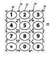
- FIG. 1shows a telephone keypad with alphabet and punctuation characters available for output by auxiliary function graphics 14 .
- the primary graphic characters 10are numeric and located on the centers of traditional keys 12
- auxiliary function graphics 14(shown here as alphabetic) are disposed on the traditional keys 12 to the upper left, lower left, upper right, and lower right.
- Locator nubs 16are disposed on the housing 18 approximately equidistant from adjacent keys, and are also included around the periphery, spaced to complete the pattern.
- locator nubs 16is preferably quite small, just large enough to be felt; thereby providing the user a tactile reference to assist in locating her finger correctly off-center.
- interstitial sensors 20enable detection of whether the user's finger is disposed centrally over the traditional key 12 and, if not centered, an indication as to which quadrant the finger is displaced toward. For example, if the four sensors around the number “8” indicate that the finger is centered over the key, the system will produce the output “8” when the underlying switch 30 is activated. If the four sensors around the number “8” indicate that the finger is displaced to the lower left, the system will produce the output “V” when the switch 30 is activated.
- Locator nubs 16may be a variety of shapes such as a small pip, mound or circle.
- FIG. 2shows an alternate embodiment in which the graphics identifying the additional characters are located on the housing 18 .
- This embodimentis otherwise the same as the one of FIG. 1 , although the finger position sensors have been omitted for clarity.
- Each auxiliary function graphic 14is associated With the switch 30 (and thereby primary graphic character 10 ) located closest to it.
- FIG. 3shows an array of sensors 20 and switches 30 .
- Each switch 30is disposed below a traditional key of a keypad.
- the switches 30may be rubber domes, poly domes, metal domes or the like.
- the switches 30are independently addressable, either with independent lines, an array, or multiplexed.
- each sensor 20is associated with a single interstitial area between switches 30 .
- Each sensor 20may consist of a single conductive plate, forming one side of a capacitor, the other side of the capacitor being provided by the activating finger.
- each sensor 20may comprise two conductive plates forming two sides of an “open” capacitor, the presence of a sensed finger providing the effect of creating two capacitors in series, as well as having a parasitic effect.
- each sensor 20is the intersection of two perpendicular grids of sense lines. Many other capacitive sense technologies are known in the art, and are found in various applications, such as touch-sensitive elevator buttons.
- the userTo operate the keypad to produce a desired output, the user simply locates his or her finger over the graphic corresponding to the desired output and presses the associated key to actuate the underlying switch. Upon sensing that the switch has been activated, the system determines if the user intended to activate the central function corresponding to the centrally placed graphic 10 , or an auxiliary function corresponding to one of peripheral graphics 14 , either by a signal from a single sensor 20 above a given threshold, or by relative sensor signal levels. As an example of the former type, referring to the embodiment of FIG. 1 , if the capacitive value measured by the sensor 20 immediately between the buttons labeled “8” and “*” (i.e., the sensor labeled “n” in FIG.
- the algorithmmay include the absence (or reduction) of a signal from the sensor 20 located on the opposite side from the intended auxiliary function graphic 14 .
- the switch 30particularly the tactile feedback metal dome element of switch 30 , may be used as one side of the local capacitor.
- FIG. 4shows another embodiment of the sensor 20 and switch 30 array, in which each switch 30 has an associated set of sensors 20 (labeled “a”, “b”, “c” and “d”) in which each member of the set is duplicated around the other switches 30 . That is to say that all of the sensors 20 labeled “a” are electrically equivalent to each other, in the sense that the control algorithm does not distinguish between activations of different ones of sensors “a”. The same is true of the other three labeled sensors (“b”, “c” and “d”) of each sets. The result is that fewer connections with the controller are required, in this case only four. However, this embodiment requires more accurate analog processing than the embodiment of FIG. 3 .
- the switch 30particularly the tactile feedback metal dome element of switch 30 , maybe used as one side of the local capacitor.
- FIG. 5shows an alternate embodiment of FIG. 4 in which alternate rows utilize different sets and adjacent sensors 20 within each row have been combined.
- identically labeled sensorsare electrically equivalent. But in this case, instead of each interstitial area 21 between switches 30 including the same four electrical entities (of sensors 20 ) differentiated by location within the interstitial area 21 (as in FIG. 4 ) adjacent rows of keys have unique sensors 20 .
- the rows “1-2-3” and “7-8-9”each have corresponding sensors “a-b-c-d”, while the rows “4-5-6” and “*-0” each have only sensors “e-f-g-h”. This lowers the demands placed upon the electronics to accurately differentiate between the sensors 20 clustered together within each interstitial area 21 .
- the two sensors 20 to the lower right of the number “5”are “g” and “a”, but as there is no instance of a type “a” sensor 20 that is supposed to be associated with the number “5”, the control algorithm will properly produce an output corresponding to the combination of switch “5” and sensor “g” and will ignore the simultaneous activation of sensor “a” when the switch “5” is activated.
- the resultis an easier standard for capacitive measurement and for output generation.
- the arrangementalso allows the system to monitor for increased measurements of non-associated sensors.
- sensors 20are disposed on a printed circuit board 22 underlying a keymat 24 with keys 12 protruding through spaced holes in a relatively rigid housing 18 .
- switches 30embodied here as metal domes.
- This figurealso shows the interaction between the user's finger 25 , as it presses off-center on the key 12 while in contact with the locator nub 16 .
- Sensors 20identify the location of the finger 25 with respect to key 12 at the moment switch 30 is activated.
- a differential measurement between the sensors 20 located on either side of a key 12is an effective way to determine the intended position of the user's finger 25 . If the differential measurement exceeds a threshold value, finger 25 is determined to be off-center and therefore seeking to activate the function identified by the auxiliary function graphic 14 located below the finger 25 and associated with the switch 30 activated at that moment.
- sensors 20are disposed on the underside of keymat 24 .
- Conductive traces(not shown) connect the array of sensors 20 to the printed circuit board 22 .
- sensors 20are disposed on the housing 18 .
- Conductive tracesconnect the'sensors 20 to the PCB 22 .
- FIG. 9shows yet another configuration, in which the housing 1 $ is integrally molded with the keys 12 in a deflectable plastic, elastomeric or composite material.
- Conductive tracesconnect the sensors 20 to the PCB 22 .
- metal dome tactile feedback elements 32provide both tactile feedback and switch operation.
- tactile feedback elements 32are made of stainless steel domes and electrically integrated with the operation of sensors 20 by acting as a first side of a capacitor in which the second side of the capacitor is provided by sensor 20 .
Landscapes
- Engineering & Computer Science (AREA)
- Theoretical Computer Science (AREA)
- General Engineering & Computer Science (AREA)
- Human Computer Interaction (AREA)
- Physics & Mathematics (AREA)
- General Physics & Mathematics (AREA)
- Signal Processing (AREA)
- Computer Hardware Design (AREA)
- Computer Networks & Wireless Communication (AREA)
- Input From Keyboards Or The Like (AREA)
- Push-Button Switches (AREA)
- Telephone Set Structure (AREA)
Abstract
Description
- This invention relates generally to keypads for manual data input, and specifically to such keypads having discrete keys, each key having multiple associated functions.
- It is desirable to provide a keypad with many outputs (e.g., numerals, letters, punctuation marks, and predefined operations) in a small space, without excessive mechanical complexity, material or service costs. Ideally, each input should be accompanied by a single and well-defined tactile feedback, and each key should be easily and reliably manipulated by a single human finger to provide a desired input. One of the most difficult aspects of keypad design is providing the “right” tactile feel; This apparently simple task is notorious within the industry and widely known without, as people will pick up products and test them (for purchase) simply by pressing the keys, discounting the product if the keys don't “feel” right.
- It is further desirable to configure each “traditional” key to provide multiple outputs, preferably up to five outputs per key. By “traditional key” I mean a discrete key or key region disposed over an associated switch element such that when the key is pressed, the switch is closed. Typically, such keys also have associated, discrete tactile feedback elements, some of which (such as poly or metal snap domes) also provide the discrete switch function.
- Some keypad layouts and key associations have developed universal recognition as a standard. For example, the standard 12-key telephone keypad layout has established an association between numbers and letters, the letters “ABC” being associated with the number “2”, “PQRS” associated with the number “7”, and so forth. Throughout this application, the telephone keypad is used as an example of one application of the present invention. However, the technology is not necessarily limited to use with telephone keypads, but is applicable to any keypad with keys having associated central functions (e.g., the “numbers” of the telephone keypad) and peripheral functions (e.g., the letters of the telephone keypad). Any symbols, alphanumeric or others, may be used.
- Further background information onpending U.S. provisional patent application Ser. No. 60/379,241, filed May 10, 2002, and 60/401,175, filed Aug. 5, 2002, the contents of which are incorporated herein by reference, as if fully set forth.

- The present invention features a keypad having an array of keys or key regions each having an associated central function and one or more associated peripheral functions. The central function is activated by manually engaging (i.e., pressing or touching) a central region of the key, while each peripheral function is activated by manually engaging a peripheral region (i.e., a region offset from the center) of the key.
- In presently preferred embodiments, the keypad contains discrete switches that underlie associated keys and that are activated in the absence of any other input to produce an output associated with the central function of the key. The switches can be of any traditional technology known to those of skill in the art of keypad design, such as snap dome switches. Additionally, the keypad contains an array of at-a-distance finger position sensors that are each responsive to an offset position of a finger activating the switch of a given key.
- In some arrangements, the finger position sensors are disposed between adjacent keys. Where more than two functions per key are desired, each key will preferably have more than one adjacent position sensor, each sensor corresponding to a different key output. The sensors could be formed into a large single array.
- The at-a-distance finger sensing may be accomplished by various means, such as capacitive and reflected infrared technologies, although capacitance sensing is presently preferred.
- In some embodiments, a single discrete capacitive sensor is located approximately equidistant between traditional keys. By measuring absolute or relative capacitive variations, the system determines whether the user's finger is centered over the key, or intentionally off-center. If the finger is off-center, the system interprets this to mean that the user intends to access an auxiliary function, preferably a function represented graphically off-center of the selected key and in the direction in which the user has placed her finger. Because each sensor is fixed in location on the keypad, the user's intent may be readily determined.
- In some cases, small nubs are included between the keys to provide the user areference to assist in locating her finger correctly off-center.
- In some applications, a plurality of sensors is disposed at each interstitial area between adjacent keys. These sensors may be functionally organized into sets so that the system may determine the orientation of the user's finger relative to a key. When a key switch under a particular key is activated, the system interprets which of the multiple functions associated with that key is intended, based upon sensed finger position relative to the center of the key.
- Preferably, each key is provided with a central graphical element corresponding to the central function of the key. It is also preferred that each peripheral function be identified by a separate graphical element, either marked on the key itself or on a housing surface adjacent the key.
- The keypad may be in the form of a substrate assembled into a housing defining apertures through which individual keys project, or may be in the form of an exposed substrate.
- According to another aspect of the invention, a method is provided for determining user input from a keypad having a defined set of physical keys that protrude through holes in a housing, each key having an underlying electrical switch. The method includes detecting activation of a switch corresponding to one of the keys, and detecting finger position with so respect to a central region of the key corresponding to the activated switch, based on signals from an array of at-a-distance finger sensors within the keypad. Upon detecting a finger position offset from the central region of the key, an output is provided corresponding to a peripheral function associated with the key. Otherwise, an output is provided corresponding to a central function associated with the key.
- In some cases, each key is labeled both with a graphic corresponding to its central function and one or more graphics corresponding with its peripheral functions. In some other cases, each key is labeled both with a graphic corresponding to its central function, and the housing is labeled with graphics corresponding with peripheral functions of the keys.
- Various aspects of the invention can reduce the keypad space necessary to support a given number of functions, by providing multiple functions per key, without requiring the manipulation of multiple keys for each added function. With appropriate graphics, each function of a multi-function key is independently and directly and mtuitvely accessible by untrained operators. Furthermore, these additional functions may be obtained without increasing the number of contacting switches and tactile feedback elements. In the case of a traditional telephone layout with twelve discrete keys having twelve associated switches and tactile elements, for example, including the ability to sense finger offsets toward four separate quadrants per key enables a full 60 outputs (i.e., five per key).
- One of the advantages of these embodiments is that stand tactile feedback switch elements and implementation may be utilized, so that the designers may fully benefit from the years of experience they have in providing the users a specific quality of switch and feel performance. Likewise, users benefit from the tactile experience they have come to expect from keypads in general, and/or from the quality standard of a particular brand.
- The details of one or more embodiments of the invention are set forth in the accompanying drawings and the description below. Other features, objects, and advantages of the invention will be apparent from the description and drawings, and from the claims.
FIG. 1 shows an exposed surface of a first keypad.FIG. 2 shows an exposed surface of a second keypad.FIGS. 3-5 show alternative arrangements of sensors and switches, useful with either of the illustrated keypads.FIGS. 6-9 are cross-sectional views of a keypad, taken alongline FIG. 3 and illustrating four alternative keypad constructions.- Like reference symbols in the various drawings indicate like elements.
FIG. 1 shows a telephone keypad with alphabet and punctuation characters available for output byauxiliary function graphics 14. In this embodiment, the primarygraphic characters 10 are numeric and located on the centers oftraditional keys 12, and auxiliary function graphics14 (shown here as alphabetic) are disposed on thetraditional keys 12 to the upper left, lower left, upper right, and lower right. With this arrangement, the system can not only determine finger position with respect to those four quadrants, but by various combinations of signals from thesensors 20, can also determine finger position above, below, left and right.Locator nubs 16 are disposed on thehousing 18 approximately equidistant from adjacent keys, and are also included around the periphery, spaced to complete the pattern. The size ofoptional locator nubs 16 is preferably quite small, just large enough to be felt; thereby providing the user a tactile reference to assist in locating her finger correctly off-center. Whether locator nubs16 are utilized or not,interstitial sensors 20 enable detection of whether the user's finger is disposed centrally over thetraditional key 12 and, if not centered, an indication as to which quadrant the finger is displaced toward. For example, if the four sensors around the number “8” indicate that the finger is centered over the key, the system will produce the output “8” when theunderlying switch 30 is activated. If the four sensors around the number “8” indicate that the finger is displaced to the lower left, the system will produce the output “V” when theswitch 30 is activated. In all cases the user is able to use one finger to press a single key and to receive a single feedback. The purpose oflocator nubs 16 is to aid the user in positioning the finger correctly, to indicate how far off-center thefinger 25 should be placed to conclusively establish the user intends an auxiliary function.Locator nubs 16 may be a variety of shapes such as a small pip, mound or circle.FIG. 2 shows an alternate embodiment in which the graphics identifying the additional characters are located on thehousing 18. This embodiment is otherwise the same as the one ofFIG. 1 , although the finger position sensors have been omitted for clarity. Each auxiliary function graphic14 is associated With the switch30 (and thereby primary graphic character10) located closest to it.FIG. 3 shows an array ofsensors 20 and switches30. Eachswitch 30 is disposed below a traditional key of a keypad. Theswitches 30 may be rubber domes, poly domes, metal domes or the like. In this embodiment, theswitches 30 are independently addressable, either with independent lines, an array, or multiplexed. More importantly, eachsensor 20 is associated with a single interstitial area between switches30. Eachsensor 20 may consist of a single conductive plate, forming one side of a capacitor, the other side of the capacitor being provided by the activating finger. Alternatively, eachsensor 20 may comprise two conductive plates forming two sides of an “open” capacitor, the presence of a sensed finger providing the effect of creating two capacitors in series, as well as having a parasitic effect. In another example, eachsensor 20 is the intersection of two perpendicular grids of sense lines. Many other capacitive sense technologies are known in the art, and are found in various applications, such as touch-sensitive elevator buttons.- To operate the keypad to produce a desired output, the user simply locates his or her finger over the graphic corresponding to the desired output and presses the associated key to actuate the underlying switch. Upon sensing that the switch has been activated, the system determines if the user intended to activate the central function corresponding to the centrally placed graphic10, or an auxiliary function corresponding to one of
peripheral graphics 14, either by a signal from asingle sensor 20 above a given threshold, or by relative sensor signal levels. As an example of the former type, referring to the embodiment ofFIG. 1 , if the capacitive value measured by thesensor 20 immediately between the buttons labeled “8” and “*” (i.e., the sensor labeled “n” inFIG. 3 ) is above a predetermined threshold when thesensor 20 underneath the number “8” is actuated, then the system will output letter “V”. As an example of the latter type, if the capacitive value measured by thesensor 20 immediately between the buttons labeled “8” and “*” is disproportionately higher than the capacitive values measured at the other threesensors 20 immediately adjacent the “8” button when thesensor 20 underneath the number “8” is actuated, then the system will output letter “V”. The algorithm may include the absence (or reduction) of a signal from thesensor 20 located on the opposite side from the intended auxiliary function graphic14. Theswitch 30, particularly the tactile feedback metal dome element ofswitch 30, may be used as one side of the local capacitor. FIG. 4 shows another embodiment of thesensor 20 and switch30 array, in which each switch30 has an associated set of sensors20 (labeled “a”, “b”, “c” and “d”) in which each member of the set is duplicated around the other switches30. That is to say that all of thesensors 20 labeled “a” are electrically equivalent to each other, in the sense that the control algorithm does not distinguish between activations of different ones of sensors “a”. The same is true of the other three labeled sensors (“b”, “c” and “d”) of each sets. The result is that fewer connections with the controller are required, in this case only four. However, this embodiment requires more accurate analog processing than the embodiment ofFIG. 3 . Theswitch 30, particularly the tactile feedback metal dome element ofswitch 30, maybe used as one side of the local capacitor.FIG. 5 shows an alternate embodiment ofFIG. 4 in which alternate rows utilize different sets andadjacent sensors 20 within each row have been combined. As inFIG. 4 , identically labeled sensors are electrically equivalent. But in this case, instead of eachinterstitial area 21 betweenswitches 30 including the same four electrical entities (of sensors20) differentiated by location within the interstitial area21 (as inFIG. 4 ) adjacent rows of keys haveunique sensors 20. In other words, the rows “1-2-3” and “7-8-9” each have corresponding sensors “a-b-c-d”, while the rows “4-5-6” and “*-0” each have only sensors “e-f-g-h”. This lowers the demands placed upon the electronics to accurately differentiate between thesensors 20 clustered together within eachinterstitial area 21. For example, the twosensors 20 to the lower right of the number “5” are “g” and “a”, but as there is no instance of a type “a”sensor 20 that is supposed to be associated with the number “5”, the control algorithm will properly produce an output corresponding to the combination of switch “5” and sensor “g” and will ignore the simultaneous activation of sensor “a” when the switch “5” is activated. The result is an easier standard for capacitive measurement and for output generation. The arrangement also allows the system to monitor for increased measurements of non-associated sensors. Using -the same example, an increased signal measured on sensor “a” as switch “5” is pressed would indicate the user intended the output corresponding to the combination of switch “5” and sensor “g.” By comparing measurements of these associated and non-associated sensors (and by knowing their relative positions and shapes) the system may better determine finger orientation and user intention.- Referring to
FIG. 6 ,sensors 20 are disposed on a printedcircuit board 22 underlying akeymat 24 withkeys 12 protruding through spaced holes in a relativelyrigid housing 18. Also shown areswitches 30, embodied here as metal domes. This figure also shows the interaction between the user'sfinger 25, as it presses off-center on the key12 while in contact with thelocator nub 16.Sensors 20 identify the location of thefinger 25 with respect to key12 at themoment switch 30 is activated. A differential measurement between thesensors 20 located on either side of a key12 is an effective way to determine the intended position of the user'sfinger 25. If the differential measurement exceeds a threshold value,finger 25 is determined to be off-center and therefore seeking to activate the function identified by the auxiliary function graphic14 located below thefinger 25 and associated with theswitch 30 activated at that moment. - In the alternative configuration of
FIG. 7 ,sensors 20 are disposed on the underside ofkeymat 24. Conductive traces (not shown) connect the array ofsensors 20 to the printedcircuit board 22. In another construction shown inFIG. 8 ,sensors 20 are disposed on thehousing 18. Conductive traces connectthe'sensors 20 to thePCB 22.FIG. 9 shows yet another configuration, in which the housing1$ is integrally molded with thekeys 12 in a deflectable plastic, elastomeric or composite material. Conductive traces connect thesensors 20 to thePCB 22. InFIGS. 6-9 , metal dometactile feedback elements 32 provide both tactile feedback and switch operation. Also inFIGS. 6-9 ,tactile feedback elements 32 are made of stainless steel domes and electrically integrated with the operation ofsensors 20 by acting as a first side of a capacitor in which the second side of the capacitor is provided bysensor 20. - A number of embodiments of the invention have been described. Nevertheless, it will be understood that various modifications may be made without departing from the spirit and scope of the invention. Accordingly, other embodiments are within the scope of the following claims.

Claims (25)
Priority Applications (1)
| Application Number | Priority Date | Filing Date | Title |
|---|---|---|---|
| US10/513,904US7164087B2 (en) | 2002-05-10 | 2003-05-09 | Keypads with multi-function keys |
Applications Claiming Priority (4)
| Application Number | Priority Date | Filing Date | Title |
|---|---|---|---|
| US37924102P | 2002-05-10 | 2002-05-10 | |
| US40117502P | 2002-08-05 | 2002-08-05 | |
| US10/513,904US7164087B2 (en) | 2002-05-10 | 2003-05-09 | Keypads with multi-function keys |
| PCT/US2003/014733WO2003096160A2 (en) | 2002-05-10 | 2003-05-09 | Keypads with multi-function keys |
Publications (2)
| Publication Number | Publication Date |
|---|---|
| US20050247548A1true US20050247548A1 (en) | 2005-11-10 |
| US7164087B2 US7164087B2 (en) | 2007-01-16 |
Family
ID=29423665
Family Applications (1)
| Application Number | Title | Priority Date | Filing Date |
|---|---|---|---|
| US10/513,904Expired - LifetimeUS7164087B2 (en) | 2002-05-10 | 2003-05-09 | Keypads with multi-function keys |
Country Status (11)
| Country | Link |
|---|---|
| US (1) | US7164087B2 (en) |
| EP (1) | EP1509937B1 (en) |
| JP (1) | JP2005525634A (en) |
| KR (1) | KR20040108794A (en) |
| CN (1) | CN100483584C (en) |
| AT (1) | ATE426907T1 (en) |
| AU (1) | AU2003233537A1 (en) |
| BR (1) | BR0309917A (en) |
| CA (1) | CA2485397C (en) |
| DE (1) | DE60326838D1 (en) |
| WO (1) | WO2003096160A2 (en) |
Cited By (5)
| Publication number | Priority date | Publication date | Assignee | Title |
|---|---|---|---|---|
| US20070186192A1 (en)* | 2003-10-31 | 2007-08-09 | Daniel Wigdor | Concurrent data entry for a portable device |
| WO2007121185A1 (en)* | 2006-04-10 | 2007-10-25 | Digit Wireless, Inc. | Touch interface configuration |
| US20080129552A1 (en)* | 2003-10-31 | 2008-06-05 | Iota Wireless Llc | Concurrent data entry for a portable device |
| US20090166931A1 (en)* | 2008-01-02 | 2009-07-02 | Liu Chang-Li | Process for manufacturing keypad modules of non-backlighted panels |
| WO2017011711A1 (en)* | 2015-07-14 | 2017-01-19 | Interlink Electronics, Inc | Human interface device |
Families Citing this family (23)
| Publication number | Priority date | Publication date | Assignee | Title |
|---|---|---|---|---|
| US7373180B2 (en)* | 2001-05-25 | 2008-05-13 | Kyocera Wireless Corp. | Method and apparatus for accentuating graphical elements on a mobile handset housing |
| US7096036B2 (en) | 2003-09-10 | 2006-08-22 | Research In Motion Limited | Dual-mode keypad for a mobile device |
| US7505796B2 (en)* | 2004-12-28 | 2009-03-17 | Sony Ericsson Mobile Communications Ab | Keypad for portable wireless devices |
| US7272411B2 (en) | 2005-01-07 | 2007-09-18 | Research In Motion Limited | Dual-mode keypad for a mobile device |
| DE602005003639T2 (en)* | 2005-01-07 | 2008-11-13 | Research In Motion Ltd., Waterloo | Dual-mode keyboard for a mobile device |
| TWI256233B (en)* | 2005-02-23 | 2006-06-01 | Benq Corp | Portable electronic device with key mechanism |
| US7953448B2 (en)* | 2006-05-31 | 2011-05-31 | Research In Motion Limited | Keyboard for mobile device |
| US7646378B2 (en)* | 2005-09-01 | 2010-01-12 | David Hirshberg | System and method for user interface |
| EP1777609A1 (en)* | 2005-10-11 | 2007-04-25 | Sony Ericsson Mobile Communications AB | Keypad for an electronic equipment and method for operating a keypad for an electronic equipment |
| CH698138B1 (en)* | 2005-11-09 | 2009-05-29 | Abatek Internat Ag | Integrated switch respectively integrated button. |
| KR100765327B1 (en)* | 2006-05-08 | 2007-10-09 | 주식회사 애트랩 | Input device |
| EP2687942A3 (en)* | 2006-05-31 | 2014-12-10 | BlackBerry Limited | Keyboard for mobile device |
| US7834853B2 (en) | 2006-07-24 | 2010-11-16 | Motorola, Inc. | Handset keypad |
| US7991147B2 (en) | 2006-07-24 | 2011-08-02 | Motorola Mobility, Inc. | Handset device with laminated architecture |
| US20080037769A1 (en) | 2006-07-24 | 2008-02-14 | Motorola, Inc. | User interface substrate for handset device |
| CN100458666C (en)* | 2006-10-25 | 2009-02-04 | 北京中星微电子有限公司 | Method and device for regulating keyboard array |
| US20090213080A1 (en)* | 2008-02-27 | 2009-08-27 | Ke Shen Lin | Mobile phone with dialing keys of uneven surface |
| US8860684B1 (en)* | 2008-09-26 | 2014-10-14 | Cypress Semiconductor Corporation | System and method of locating a touch based on a combination of pins |
| US8633916B2 (en)* | 2009-12-10 | 2014-01-21 | Apple, Inc. | Touch pad with force sensors and actuator feedback |
| LV14249B (en)* | 2010-08-12 | 2011-04-20 | Vladimirs Bondarenko | & Imacration information &acr; ē š electronic ā s ī c ē |
| CN102736740B (en)* | 2011-04-15 | 2015-09-30 | 深圳市证通电子股份有限公司 | Encryption Keyboard and manufacture method thereof |
| TWI585674B (en)* | 2013-04-03 | 2017-06-01 | 富智康(香港)有限公司 | Event triggering system and method |
| CN104102439B (en)* | 2013-04-08 | 2019-06-18 | 深圳富泰宏精密工业有限公司 | Event triggering system and method |
Citations (8)
| Publication number | Priority date | Publication date | Assignee | Title |
|---|---|---|---|---|
| US5329278A (en)* | 1991-10-24 | 1994-07-12 | Dombroski Michael L | Pivoting electronic keyboard keys |
| US5528235A (en)* | 1991-09-03 | 1996-06-18 | Edward D. Lin | Multi-status multi-function data processing key and key array |
| US5822703A (en)* | 1993-10-08 | 1998-10-13 | Canon Kabushiki Kaisha | Portable telephone with dial keys and line keys mounted on different surfaces |
| US5841374A (en)* | 1997-01-28 | 1998-11-24 | Abraham; Joseph N. | Micro word-pad with tactile multifunctional keys |
| US5852414A (en)* | 1995-01-04 | 1998-12-22 | Yu; Seymour H. | 4-way triangular-shaped alphanumeric keyboard |
| US6259044B1 (en)* | 2000-03-03 | 2001-07-10 | Intermec Ip Corporation | Electronic device with tactile keypad-overlay |
| US20020014395A1 (en)* | 2000-08-02 | 2002-02-07 | Koninklijke Philips Electronics N.V. | Text entry on portable device |
| US6541715B2 (en)* | 2001-05-24 | 2003-04-01 | Philip Swanson | Alphanumeric keyboard for hand-held electronic devices |
Family Cites Families (3)
| Publication number | Priority date | Publication date | Assignee | Title |
|---|---|---|---|---|
| US5612690A (en) | 1993-06-03 | 1997-03-18 | Levy; David | Compact keypad system and method |
| US5973621A (en) | 1993-06-03 | 1999-10-26 | Levy; David | Compact keyed input device |
| WO2001095358A2 (en)* | 2000-05-22 | 2001-12-13 | Digit Wireless, Llc | Input devices and their use |
- 2003
- 2003-05-09ATAT03728815Tpatent/ATE426907T1/ennot_activeIP Right Cessation
- 2003-05-09AUAU2003233537Apatent/AU2003233537A1/ennot_activeAbandoned
- 2003-05-09USUS10/513,904patent/US7164087B2/ennot_activeExpired - Lifetime
- 2003-05-09WOPCT/US2003/014733patent/WO2003096160A2/enactiveApplication Filing
- 2003-05-09KRKR10-2004-7018139Apatent/KR20040108794A/ennot_activeCeased
- 2003-05-09BRBR0309917-2Apatent/BR0309917A/ennot_activeIP Right Cessation
- 2003-05-09CACA2485397Apatent/CA2485397C/ennot_activeExpired - Fee Related
- 2003-05-09DEDE60326838Tpatent/DE60326838D1/ennot_activeExpired - Lifetime
- 2003-05-09EPEP03728815Apatent/EP1509937B1/ennot_activeExpired - Lifetime
- 2003-05-09CNCNB038106000Apatent/CN100483584C/ennot_activeExpired - Lifetime
- 2003-05-09JPJP2004504087Apatent/JP2005525634A/enactivePending
Patent Citations (9)
| Publication number | Priority date | Publication date | Assignee | Title |
|---|---|---|---|---|
| US5528235A (en)* | 1991-09-03 | 1996-06-18 | Edward D. Lin | Multi-status multi-function data processing key and key array |
| US5329278A (en)* | 1991-10-24 | 1994-07-12 | Dombroski Michael L | Pivoting electronic keyboard keys |
| US5822703A (en)* | 1993-10-08 | 1998-10-13 | Canon Kabushiki Kaisha | Portable telephone with dial keys and line keys mounted on different surfaces |
| US5852414A (en)* | 1995-01-04 | 1998-12-22 | Yu; Seymour H. | 4-way triangular-shaped alphanumeric keyboard |
| US5841374A (en)* | 1997-01-28 | 1998-11-24 | Abraham; Joseph N. | Micro word-pad with tactile multifunctional keys |
| US6259044B1 (en)* | 2000-03-03 | 2001-07-10 | Intermec Ip Corporation | Electronic device with tactile keypad-overlay |
| US20020014395A1 (en)* | 2000-08-02 | 2002-02-07 | Koninklijke Philips Electronics N.V. | Text entry on portable device |
| US6528741B2 (en)* | 2000-08-02 | 2003-03-04 | Koninklijke Philips Electronics N.V. | Text entry on portable device |
| US6541715B2 (en)* | 2001-05-24 | 2003-04-01 | Philip Swanson | Alphanumeric keyboard for hand-held electronic devices |
Cited By (9)
| Publication number | Priority date | Publication date | Assignee | Title |
|---|---|---|---|---|
| US20070186192A1 (en)* | 2003-10-31 | 2007-08-09 | Daniel Wigdor | Concurrent data entry for a portable device |
| US20080129552A1 (en)* | 2003-10-31 | 2008-06-05 | Iota Wireless Llc | Concurrent data entry for a portable device |
| US7721968B2 (en)* | 2003-10-31 | 2010-05-25 | Iota Wireless, Llc | Concurrent data entry for a portable device |
| WO2007121185A1 (en)* | 2006-04-10 | 2007-10-25 | Digit Wireless, Inc. | Touch interface configuration |
| US20090166931A1 (en)* | 2008-01-02 | 2009-07-02 | Liu Chang-Li | Process for manufacturing keypad modules of non-backlighted panels |
| WO2017011711A1 (en)* | 2015-07-14 | 2017-01-19 | Interlink Electronics, Inc | Human interface device |
| US10203767B2 (en) | 2015-07-14 | 2019-02-12 | Interlink Electronics, Inc. | Human interface device |
| US10409389B2 (en) | 2015-07-14 | 2019-09-10 | Interlink Electronics, Inc. | Human interface device |
| US10948998B2 (en) | 2015-07-14 | 2021-03-16 | Interlink Electronics, Inc. | Human interface device |
Also Published As
| Publication number | Publication date |
|---|---|
| EP1509937A2 (en) | 2005-03-02 |
| AU2003233537A8 (en) | 2003-11-11 |
| ATE426907T1 (en) | 2009-04-15 |
| KR20040108794A (en) | 2004-12-24 |
| EP1509937A4 (en) | 2006-05-03 |
| US7164087B2 (en) | 2007-01-16 |
| BR0309917A (en) | 2005-02-09 |
| CA2485397A1 (en) | 2003-11-20 |
| WO2003096160A3 (en) | 2004-02-05 |
| WO2003096160A2 (en) | 2003-11-20 |
| DE60326838D1 (en) | 2009-05-07 |
| EP1509937B1 (en) | 2009-03-25 |
| CA2485397C (en) | 2012-07-10 |
| JP2005525634A (en) | 2005-08-25 |
| AU2003233537A1 (en) | 2003-11-11 |
| CN100483584C (en) | 2009-04-29 |
| CN1653570A (en) | 2005-08-10 |
Similar Documents
| Publication | Publication Date | Title |
|---|---|---|
| US7164087B2 (en) | Keypads with multi-function keys | |
| US8441447B2 (en) | Touch sensor keypad with tactile feedback mechanisms and electronic device with the same | |
| US7978181B2 (en) | Keystroke tactility arrangement on a smooth touch surface | |
| EP1290705B1 (en) | Input devices and their use | |
| KR101021157B1 (en) | Keypad and key switch | |
| US5612690A (en) | Compact keypad system and method | |
| US9443672B2 (en) | Patterned conductive traces in molded elastomere substrate | |
| US9349551B2 (en) | Keyboard with elastic member disposed on touch panel | |
| US20100040400A1 (en) | Keyboard and keys | |
| US20130135213A1 (en) | Sensing capacitance changes of a housing of an electronic device | |
| US20080028309A1 (en) | Input device | |
| US5926119A (en) | Numeric keypad configuration | |
| US20060119581A1 (en) | Keyboard improvements | |
| KR20090019985A (en) | Piezoelectric Sensing Unit | |
| HK1081722A (en) | Keypads with multi-function keys | |
| US11561624B2 (en) | Capacitive touch enabled key with a corresponding tactile button | |
| EP1681695B1 (en) | Electrical key switch | |
| JPH03134725A (en) | Keyboard | |
| HK1073530B (en) | Keypads and key switches | |
| HK1093605B (en) | Electrical key switch |
Legal Events
| Date | Code | Title | Description |
|---|---|---|---|
| AS | Assignment | Owner name:DIGIT WIRELESS, LLC, MASSACHUSETTS Free format text:ASSIGNMENT OF ASSIGNORS INTEREST;ASSIGNOR:LEVY, DAVID H.;REEL/FRAME:014404/0640 Effective date:20030805 | |
| AS | Assignment | Owner name:DIGIT WIRELESS, LLC, MASSACHUSETTS Free format text:ASSIGNMENT OF ASSIGNORS INTEREST;ASSIGNOR:LEVY, DAVID H.;REEL/FRAME:016332/0875 Effective date:20041208 | |
| STCF | Information on status: patent grant | Free format text:PATENTED CASE | |
| FEPP | Fee payment procedure | Free format text:PAYOR NUMBER ASSIGNED (ORIGINAL EVENT CODE: ASPN); ENTITY STATUS OF PATENT OWNER: LARGE ENTITY | |
| FPAY | Fee payment | Year of fee payment:4 | |
| FEPP | Fee payment procedure | Free format text:PAYER NUMBER DE-ASSIGNED (ORIGINAL EVENT CODE: RMPN); ENTITY STATUS OF PATENT OWNER: LARGE ENTITY Free format text:PAYOR NUMBER ASSIGNED (ORIGINAL EVENT CODE: ASPN); ENTITY STATUS OF PATENT OWNER: LARGE ENTITY | |
| FEPP | Fee payment procedure | Free format text:PAT HOLDER NO LONGER CLAIMS SMALL ENTITY STATUS, ENTITY STATUS SET TO UNDISCOUNTED (ORIGINAL EVENT CODE: STOL); ENTITY STATUS OF PATENT OWNER: LARGE ENTITY | |
| REFU | Refund | Free format text:REFUND - PAYMENT OF MAINTENANCE FEE, 8TH YR, SMALL ENTITY (ORIGINAL EVENT CODE: R2552); ENTITY STATUS OF PATENT OWNER: LARGE ENTITY | |
| FPAY | Fee payment | Year of fee payment:8 | |
| MAFP | Maintenance fee payment | Free format text:PAYMENT OF MAINTENANCE FEE, 12TH YEAR, LARGE ENTITY (ORIGINAL EVENT CODE: M1553) Year of fee payment:12 | |
| AS | Assignment | Owner name:CERENCE INC., MASSACHUSETTS Free format text:INTELLECTUAL PROPERTY AGREEMENT;ASSIGNOR:NUANCE COMMUNICATIONS, INC.;REEL/FRAME:050836/0191 Effective date:20190930 | |
| AS | Assignment | Owner name:CERENCE OPERATING COMPANY, MASSACHUSETTS Free format text:CORRECTIVE ASSIGNMENT TO CORRECT THE ASSIGNEE NAME PREVIOUSLY RECORDED AT REEL: 050836 FRAME: 0191. ASSIGNOR(S) HEREBY CONFIRMS THE INTELLECTUAL PROPERTY AGREEMENT;ASSIGNOR:NUANCE COMMUNICATIONS, INC.;REEL/FRAME:050871/0001 Effective date:20190930 | |
| AS | Assignment | Owner name:BARCLAYS BANK PLC, NEW YORK Free format text:SECURITY AGREEMENT;ASSIGNOR:CERENCE OPERATING COMPANY;REEL/FRAME:050953/0133 Effective date:20191001 | |
| AS | Assignment | Owner name:CERENCE OPERATING COMPANY, MASSACHUSETTS Free format text:RELEASE BY SECURED PARTY;ASSIGNOR:BARCLAYS BANK PLC;REEL/FRAME:052927/0335 Effective date:20200612 | |
| AS | Assignment | Owner name:WELLS FARGO BANK, N.A., NORTH CAROLINA Free format text:SECURITY AGREEMENT;ASSIGNOR:CERENCE OPERATING COMPANY;REEL/FRAME:052935/0584 Effective date:20200612 | |
| AS | Assignment | Owner name:CERENCE OPERATING COMPANY, MASSACHUSETTS Free format text:CORRECTIVE ASSIGNMENT TO CORRECT THE REPLACE THE CONVEYANCE DOCUMENT WITH THE NEW ASSIGNMENT PREVIOUSLY RECORDED AT REEL: 050836 FRAME: 0191. ASSIGNOR(S) HEREBY CONFIRMS THE ASSIGNMENT;ASSIGNOR:NUANCE COMMUNICATIONS, INC.;REEL/FRAME:059804/0186 Effective date:20190930 | |
| AS | Assignment | Owner name:CERENCE OPERATING COMPANY, MASSACHUSETTS Free format text:RELEASE (REEL 052935 / FRAME 0584);ASSIGNOR:WELLS FARGO BANK, NATIONAL ASSOCIATION;REEL/FRAME:069797/0818 Effective date:20241231 |