US20050200404A1 - Amplifier circuit - Google Patents
Amplifier circuitDownload PDFInfo
- Publication number
- US20050200404A1 US20050200404A1US11/032,703US3270305AUS2005200404A1US 20050200404 A1US20050200404 A1US 20050200404A1US 3270305 AUS3270305 AUS 3270305AUS 2005200404 A1US2005200404 A1US 2005200404A1
- Authority
- US
- United States
- Prior art keywords
- signal
- output
- amplifier circuit
- input
- circuit
- Prior art date
- Legal status (The legal status is an assumption and is not a legal conclusion. Google has not performed a legal analysis and makes no representation as to the accuracy of the status listed.)
- Granted
Links
Images

Classifications
- H—ELECTRICITY
- H03—ELECTRONIC CIRCUITRY
- H03F—AMPLIFIERS
- H03F3/00—Amplifiers with only discharge tubes or only semiconductor devices as amplifying elements
- H03F3/45—Differential amplifiers
- H03F3/45071—Differential amplifiers with semiconductor devices only
- H03F3/45076—Differential amplifiers with semiconductor devices only characterised by the way of implementation of the active amplifying circuit in the differential amplifier
- H03F3/45475—Differential amplifiers with semiconductor devices only characterised by the way of implementation of the active amplifying circuit in the differential amplifier using IC blocks as the active amplifying circuit
- H—ELECTRICITY
- H03—ELECTRONIC CIRCUITRY
- H03F—AMPLIFIERS
- H03F3/00—Amplifiers with only discharge tubes or only semiconductor devices as amplifying elements
- H03F3/189—High-frequency amplifiers, e.g. radio frequency amplifiers
- H03F3/19—High-frequency amplifiers, e.g. radio frequency amplifiers with semiconductor devices only
- H03F3/195—High-frequency amplifiers, e.g. radio frequency amplifiers with semiconductor devices only in integrated circuits
- H—ELECTRICITY
- H03—ELECTRONIC CIRCUITRY
- H03F—AMPLIFIERS
- H03F3/00—Amplifiers with only discharge tubes or only semiconductor devices as amplifying elements
- H03F3/20—Power amplifiers, e.g. Class B amplifiers, Class C amplifiers
- H03F3/21—Power amplifiers, e.g. Class B amplifiers, Class C amplifiers with semiconductor devices only
- H03F3/217—Class D power amplifiers; Switching amplifiers
- H03F3/2173—Class D power amplifiers; Switching amplifiers of the bridge type
- H—ELECTRICITY
- H03—ELECTRONIC CIRCUITRY
- H03F—AMPLIFIERS
- H03F2200/00—Indexing scheme relating to amplifiers
- H03F2200/351—Pulse width modulation being used in an amplifying circuit
- H—ELECTRICITY
- H03—ELECTRONIC CIRCUITRY
- H03F—AMPLIFIERS
- H03F2203/00—Indexing scheme relating to amplifiers with only discharge tubes or only semiconductor devices as amplifying elements covered by H03F3/00
- H03F2203/45—Indexing scheme relating to differential amplifiers
- H03F2203/45078—Indexing scheme relating to differential amplifiers the common mode signal being taken or deducted from the one or more inputs of the differential amplifier
Definitions
- the present inventionrelates to an amplifier circuit.
- Audio signalsare normally amplified using class D amplifiers, inter alia.
- a reference signalis first compared with a signal fed back from the output and a corresponding error signal is output.
- This signalis processed on a pulse width modulation basis using a sawtooth signal and is passed to an output amplifier stage.
- the output stageis operated so as to switch at a particular duty ratio.
- a freewheeling diode and an inductorare provided at the output. It is thus possible to provide a constant output current at the output.
- FIG. 1 in the “Journal of the Audio Engineering Society”, Audio Engineering Society, New York, USA, vol. 39, No. 9, Sep. 1, 1991, pages 650, 662shows an amplifier circuit with a differential amplifier whose output side is connected to a first input on a comparator. A second input on the comparator is supplied with a sawtooth-waveform signal. The output side of the comparator is connected to an output circuit which is pulse width modulated.
- Printed document EP 0503571 A1likewise shows a pulse width modulated amplifier circuit whose signal input is connected to a comparator. A second input on the comparator is supplied with a sawtooth-waveform signal. The output of the comparator is connected to an output stage.
- the gain of the transfer function Vout/Vinis accordingly proportional to the duty ratio d, which may be between 0 and 1.
- this termdetermines the denominator of the formula for describing the power supply rejection ratio. Accordingly, fluctuations in the supply voltage or radio-frequency interference components in the supply voltage result in relatively severe unwanted effects on the output signal from the amplifier circuit.
- a further problem of the principle describedis the unwanted convolution of signals. If the supply voltage for the output stage behaves like a relatively low-frequency sinusoidal oscillation but the useful signal is likewise a (higher-frequency) sinusoidal oscillation, then the low-level signal gain also varies sinusoidally. The resultant harmonics are at the summed frequency and the differential frequency between the frequencies of the two signals at an amplitude which corresponds to half of the product of the amplitudes of the two signals. The problem is of great significance particularly because the interference may be at frequencies below the cut-off frequency of the low-pass filter at the output and is therefore not filtered out.
- the relatively poor power supply rejection ratiois normally countered by increasing the signal gain. This increases the power consumption, however.
- the convolution problems describedmay be reduced by reducing the noise components and interference components on the supply voltage, for example by using a linear controller. This severely reduces the efficiency of the amplifier, however.
- the present inventionis directed to an amplifier circuit which operates on the basis of the class D principle and has an improved power supply rejection ratio.
- the amplifier circuitcomprises an input for supplying a useful signal which is to be amplified, and an output for tapping off an amplified useful signal.
- the circuitfurther comprises a differential amplifier having a first input, which is connected to the input of the amplifier circuit, a second input, which is coupled to the output of the amplifier circuit, and an output.
- a comparatoris also provided having a first input, which is connected to the output of the differential amplifier, and a second input, to which a periodic signal is supplied, along with an output stage having an input, which is connected to an output of the comparator, an output, and having a supply connection for supplying a supply voltage thereto.
- the circuitalso comprises a signal generator which is connected to the second input of the comparator and provides the periodic signal at an amplitude which is proportional to the supply voltage for the output stage.
- the signal generatoris configured in a phase locked loop to regulate the frequency of the periodic signal on the basis of a reference clock.
- the periodic signal used for pulse width modulationis provided such that its amplitude is always proportional to the supply voltage for the amplifier circuit, particularly for the output stage of the amplifier circuit.
- the duty ratiois always proportional to the supply voltage.
- the transfer function for the output voltage in relation to the supply voltage in consideration of the low-level signal responseis ideally 0, in practical terms at least very low, which means that the power supply rejection ratio PSRR is greatly improved.
- the quotient of the supply voltage and the amplitude voltage of the periodic signalis always constant in one example of the present invention.
- this quotientalso describes the low-level signal gain, in particular, of the circuit, and the circuit described accordingly always operates at constant gain such that an additional advantage is that no convolution with a harmonic signal component of the supply voltage may arise.
- the periodic signalwhich, in accordance with the present invention, is used for pulse width modulation, is a ramp signal, a triangular-waveform signal or a sawtooth signal, for example, then the proportionality of this signal to the supply voltage relates to the fact that the peak-to-peak voltage of the ramp signal is proportional to the supply voltage.
- the proportionality of the periodic signal to the supply voltageis produced, in one example, using an operational amplifier whose input side is connected to the supply voltage and whose output side is coupled to the signal generator in order to feed it.
- the amplifier circuit described in one exampleis preferably of symmetrical design with two output stages which are each preferably in the form of inverters.
- the output nodes of the invertersare each preferably coupled to the output terminals of the output of the amplifier circuit via a series inductor.
- a stabilization capacitanceis preferably connected between the two output terminals.
- a digital implementation of the present inventionis contemplated, wherein provision is made for the duty ratio always to be set proportionally to the supply voltage.
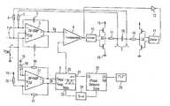
- FIG. 1is a block diagram illustrating an amplifier circuit according to an exemplary embodiment of the present invention.
- FIG. 1shows an amplifier circuit based on the present invention using a block diagram.
- This circuitcomprises an input 1 for supplying a useful signal to be amplified which is in the form of a symmetrical input with a pair of differential input terminals.
- the signal amplified using the present amplifier circuitwhich signal is derived from the signal applied to the input 1 , can be tapped off at the output 2 , which is likewise symmetrically in the form of a pair of output terminals.
- the input 1has an amplifier 3 connected to it which forms a differential signal from the signal difference between the signal applied to the input 1 and the signal provided at the output 2 .
- This differential signalis provided at the symmetrical input of the operational amplifier 3 .
- the pair of output terminals 2is connected to the input of the amplifier 3 via a respective resistor 4 , 5 .
- the two output terminals of the operational amplifier 3are connected to the two inputs of the amplifier 3 in an inverting feedback loop via a respective capacitor 6 , 7 .
- the amplifier 3also has a common-mode input for supplying a common-mode level V cm . A common-mode signal may be supplied to this common-mode input.
- CMOS inverter 13 , 14Connected to one of the two output terminals of the differential amplifier 3 is the positive input of a comparator 8 , whose negative input is connected to a signal generator 9 .
- the output of the comparator 8 designed for pulse width modulation PWMis connected to a first output driver 10 l directly and to a second output driver 11 via an inverter 12 .
- the output drivers 10 , 11are respectively connected to the control inputs of a CMOS inverter 13 , 14 .
- the CMOS inverters 13 , 14each comprise a load-side series circuit comprising a p-channel MOS transistor and an n-channel MOS transistor which are connected between a supply potential connection 15 and a reference potential connection 16 , as is usual for CMOS inverters.
- the outputs of the CMOS inverters 13 , 14which form the output stages of the present amplifier, each have their output node at the connecting node for the MOS transistors. These output nodes are connected to the output terminals 2 via a respective series inductor 17 , 18 . Connected between the output terminals 2 is a stabilization capacitance 19 which forms an LC filter together with the series inductors 17 , 18 .
- the signal generator 9is in the form of a triangular-waveform signal generator which provides a periodic signal having a peak-to-peak voltage V max -V min at an output 20 , said voltage being obtained from the difference between an upper peak value V max and a lower peak valve V min .
- the frequency (conditioned as a digital clock signal) of the periodic signal provided by the signal generatoris provided at a digital clock output 21 which is connected to a first input on a phase detector 22 .
- a further input on the phase detector 22is connected to a reference clock source 23 .
- the output of the phase detector 22which provides any phase error between the two input signals, is routed via a voltage/current converter 24 to the quiescent current input 25 of the signal generator 9 .
- the amplitude V max -V minis set at a symmetrically designed amplitude control input 26 on the signal generator 9 .
- Connected to this inputis the differential output of a further operational amplifier 27 .
- the negative input of the operational amplifier 27is connected to reference potential 16 via a resistor 28 .
- the positive input of the operational amplifier 27is connected to supply potential connection 15 via a further resistor 29 .
- the supply and reference potential connections 15 , 16match the supply voltage connections 15 , 16 of the output stages 13 , 14 in the amplifier.
- the operational amplifier 27likewise has a common-mode input which is connected to the common-mode input of the operational amplifier 3 for the purpose of supplying the common-mode signal V cm .
- the operational amplifier 27has a negative feedback loop from the differential output to the differential input via a respective resistor 30 , 31 .
- the peak-to-peak voltage V max -V min of the ramp signal provided by the signal generator 9is proportional to the supply voltage for the amplifier.
- the bias current of the signal generator 9is controlled by a phase locked loop in order to keep the frequency of the periodic signal constant while the peak-to-peak voltage V max -V min changes.
- the present amplifier circuitsignificantly improves the linearity of the output stage. A further improvement could be attained, by way of example, by increasing the bandwidth of the open loop gain. With the feed-forward technology presented, there is no need for error compensation for any interference components on the supply voltage.
- the principle describednamely the setting of the peak-to-peak voltage of the periodic signal proportionally to the supply voltage, allows a significant improvement in the power supply rejection ratio and at the same time makes it possible to avoid unwanted convolution effects to a large extent.
- the principle describedcan be implemented using particularly simple circuit means and with little complexity.
- a digital implementationmay also be provided.
- the supply voltagewould be converted into a digital voltage signal using an analog/digital converter, and the duty ratio of the pulse width modulation would be tracked proportionally to the supply voltage.
Landscapes
- Engineering & Computer Science (AREA)
- Power Engineering (AREA)
- Microelectronics & Electronic Packaging (AREA)
- Amplifiers (AREA)
Abstract
Description
- This application is a continuation of PCT/DE03/02304, which was not published in English, that claims the benefit of the priority date of German Patent Application No. DE 102 31 183.8, filed on Jul. 10, 2002, the contents of which are herein incorporated by reference in their entirety.
- The present invention relates to an amplifier circuit.
- Audio signals are normally amplified using class D amplifiers, inter alia. In line with the underlying principle, a reference signal is first compared with a signal fed back from the output and a corresponding error signal is output. This signal is processed on a pulse width modulation basis using a sawtooth signal and is passed to an output amplifier stage. In this case, the output stage is operated so as to switch at a particular duty ratio. To maintain a flow of current at the output, a freewheeling diode and an inductor are provided at the output. It is thus possible to provide a constant output current at the output.
FIG. 1 in the “Journal of the Audio Engineering Society”, Audio Engineering Society, New York, USA, vol. 39, No. 9, Sep. 1, 1991, pages 650, 662 shows an amplifier circuit with a differential amplifier whose output side is connected to a first input on a comparator. A second input on the comparator is supplied with a sawtooth-waveform signal. The output side of the comparator is connected to an output circuit which is pulse width modulated.- Printed document EP 0503571 A1 likewise shows a pulse width modulated amplifier circuit whose signal input is connected to a comparator. A second input on the comparator is supplied with a sawtooth-waveform signal. The output of the comparator is connected to an output stage.
- However, such amplifiers have relatively poor properties in terms of the power supply rejection ratio (PSRR). If the low-level signal response of a circuit of this type is considered, the ratio of the output voltage to the input voltage is
where L and C are the values of an LC filter at the output and d is the duty ratio of the pulse width modulation. The gain of the transfer function Vout/Vin is accordingly proportional to the duty ratio d, which may be between 0 and 1. However, this term determines the denominator of the formula for describing the power supply rejection ratio. Accordingly, fluctuations in the supply voltage or radio-frequency interference components in the supply voltage result in relatively severe unwanted effects on the output signal from the amplifier circuit. - A further problem of the principle described is the unwanted convolution of signals. If the supply voltage for the output stage behaves like a relatively low-frequency sinusoidal oscillation but the useful signal is likewise a (higher-frequency) sinusoidal oscillation, then the low-level signal gain also varies sinusoidally. The resultant harmonics are at the summed frequency and the differential frequency between the frequencies of the two signals at an amplitude which corresponds to half of the product of the amplitudes of the two signals. The problem is of great significance particularly because the interference may be at frequencies below the cut-off frequency of the low-pass filter at the output and is therefore not filtered out.
- The relatively poor power supply rejection ratio is normally countered by increasing the signal gain. This increases the power consumption, however.
- The convolution problems described may be reduced by reducing the noise components and interference components on the supply voltage, for example by using a linear controller. This severely reduces the efficiency of the amplifier, however.
- The following presents a simplified summary in order to provide a basic understanding of one or more aspects of the invention. This summary is not an extensive overview of the invention, and is neither intended to identify key or critical elements of the invention, nor to delineate the scope thereof. Rather, the primary purpose of the summary is to present one or more concepts of the invention in a simplified form as a prelude to the more detailed description that is presented later.
- The present invention is directed to an amplifier circuit which operates on the basis of the class D principle and has an improved power supply rejection ratio.
- In one embodiment of the invention, the amplifier circuit comprises an input for supplying a useful signal which is to be amplified, and an output for tapping off an amplified useful signal. The circuit further comprises a differential amplifier having a first input, which is connected to the input of the amplifier circuit, a second input, which is coupled to the output of the amplifier circuit, and an output. A comparator is also provided having a first input, which is connected to the output of the differential amplifier, and a second input, to which a periodic signal is supplied, along with an output stage having an input, which is connected to an output of the comparator, an output, and having a supply connection for supplying a supply voltage thereto. The circuit also comprises a signal generator which is connected to the second input of the comparator and provides the periodic signal at an amplitude which is proportional to the supply voltage for the output stage. The signal generator is configured in a phase locked loop to regulate the frequency of the periodic signal on the basis of a reference clock.
- In accordance with the present invention, the periodic signal used for pulse width modulation is provided such that its amplitude is always proportional to the supply voltage for the amplifier circuit, particularly for the output stage of the amplifier circuit.
- In accordance with another exemplary embodiment of the invention, the duty ratio is always proportional to the supply voltage.
- In accordance with yet another embodiment of the invention, the transfer function for the output voltage in relation to the supply voltage in consideration of the low-level signal response is ideally 0, in practical terms at least very low, which means that the power supply rejection ratio PSRR is greatly improved.
- The quotient of the supply voltage and the amplitude voltage of the periodic signal is always constant in one example of the present invention. However, this quotient also describes the low-level signal gain, in particular, of the circuit, and the circuit described accordingly always operates at constant gain such that an additional advantage is that no convolution with a harmonic signal component of the supply voltage may arise.
- If the periodic signal, which, in accordance with the present invention, is used for pulse width modulation, is a ramp signal, a triangular-waveform signal or a sawtooth signal, for example, then the proportionality of this signal to the supply voltage relates to the fact that the peak-to-peak voltage of the ramp signal is proportional to the supply voltage.
- The proportionality of the periodic signal to the supply voltage is produced, in one example, using an operational amplifier whose input side is connected to the supply voltage and whose output side is coupled to the signal generator in order to feed it.
- So that the frequency of the periodic signal always remains constant despite the amplitude of the signal being linked to a possibly fluctuating supply voltage, there is advantageously provided a phase locked loop which ensures that the signal generator's frequency is constant.
- The amplifier circuit described in one example is preferably of symmetrical design with two output stages which are each preferably in the form of inverters. The output nodes of the inverters are each preferably coupled to the output terminals of the output of the amplifier circuit via a series inductor. A stabilization capacitance is preferably connected between the two output terminals.
- In one alternative, a digital implementation of the present invention is contemplated, wherein provision is made for the duty ratio always to be set proportionally to the supply voltage.
- To the accomplishment of the foregoing and related ends, the invention comprises the features hereinafter fully described and particularly pointed out in the claims. The following description and the annexed drawings set forth in detail certain illustrative aspects and implementations of the invention. These are indicative, however, of but a few of the various ways in which the principles of the invention may be employed. Other objects, advantages and novel features of the invention will become apparent from the following detailed description of the invention when considered in conjunction with the drawings.
- The invention is explained below using an exemplary embodiment with reference to the figure.
FIG. 1 is a block diagram illustrating an amplifier circuit according to an exemplary embodiment of the present invention.FIG. 1 shows an amplifier circuit based on the present invention using a block diagram. This circuit comprises aninput 1 for supplying a useful signal to be amplified which is in the form of a symmetrical input with a pair of differential input terminals. The signal amplified using the present amplifier circuit, which signal is derived from the signal applied to theinput 1, can be tapped off at the output2, which is likewise symmetrically in the form of a pair of output terminals.- The
input 1 has anamplifier 3 connected to it which forms a differential signal from the signal difference between the signal applied to theinput 1 and the signal provided at the output2. This differential signal is provided at the symmetrical input of theoperational amplifier 3. For this, the pair of output terminals2 is connected to the input of theamplifier 3 via arespective resistor 4,5. In addition, the two output terminals of theoperational amplifier 3 are connected to the two inputs of theamplifier 3 in an inverting feedback loop via arespective capacitor amplifier 3 also has a common-mode input for supplying a common-mode level Vcm. A common-mode signal may be supplied to this common-mode input. - Connected to one of the two output terminals of the
differential amplifier 3 is the positive input of acomparator 8, whose negative input is connected to asignal generator 9. The output of thecomparator 8 designed for pulse width modulation PWM is connected to a first output driver10l directly and to asecond output driver 11 via aninverter 12. Theoutput drivers CMOS inverter potential connection 15 and a referencepotential connection 16, as is usual for CMOS inverters. The outputs of theCMOS inverters respective series inductor stabilization capacitance 19 which forms an LC filter together with theseries inductors - The
signal generator 9 is in the form of a triangular-waveform signal generator which provides a periodic signal having a peak-to-peak voltage Vmax-Vminat anoutput 20, said voltage being obtained from the difference between an upper peak value Vmaxand a lower peak valve Vmin. - The frequency (conditioned as a digital clock signal) of the periodic signal provided by the signal generator is provided at a
digital clock output 21 which is connected to a first input on aphase detector 22. A further input on thephase detector 22 is connected to areference clock source 23. The output of thephase detector 22, which provides any phase error between the two input signals, is routed via a voltage/current converter 24 to the quiescentcurrent input 25 of thesignal generator 9. - The amplitude Vmax-Vminis set at a symmetrically designed
amplitude control input 26 on thesignal generator 9. Connected to this input is the differential output of a furtheroperational amplifier 27. The negative input of theoperational amplifier 27 is connected to reference potential16 via aresistor 28. The positive input of theoperational amplifier 27 is connected to supplypotential connection 15 via afurther resistor 29. In this case, the supply and referencepotential connections supply voltage connections operational amplifier 27 likewise has a common-mode input which is connected to the common-mode input of theoperational amplifier 3 for the purpose of supplying the common-mode signal Vcm. Theoperational amplifier 27 has a negative feedback loop from the differential output to the differential input via arespective resistor - It can clearly be seen that the peak-to-peak voltage Vmax-Vminof the ramp signal provided by the
signal generator 9 is proportional to the supply voltage for the amplifier. The bias current of thesignal generator 9 is controlled by a phase locked loop in order to keep the frequency of the periodic signal constant while the peak-to-peak voltage Vmax-Vminchanges. When designing the circuit, it is important to remember that the bandwidths of the two control loops, namely that of the amplifier and that of the phase controller, are greater than the cut-off frequency of the low-pass filter. - The present amplifier circuit significantly improves the linearity of the output stage. A further improvement could be attained, by way of example, by increasing the bandwidth of the open loop gain. With the feed-forward technology presented, there is no need for error compensation for any interference components on the supply voltage.
- As already explained, the principle described, namely the setting of the peak-to-peak voltage of the periodic signal proportionally to the supply voltage, allows a significant improvement in the power supply rejection ratio and at the same time makes it possible to avoid unwanted convolution effects to a large extent. In this case, the principle described can be implemented using particularly simple circuit means and with little complexity.
- Instead of the illustrated analog actuation of the
reference signal generator 9 with the aim of keeping the duty ratio constant regardless of the supply voltage, a digital implementation may also be provided. For this, the supply voltage would be converted into a digital voltage signal using an analog/digital converter, and the duty ratio of the pulse width modulation would be tracked proportionally to the supply voltage. - While the invention has been illustrated and described with respect to one or more implementations, alterations and/or modifications may be made to the illustrated examples without departing from the spirit and scope of the appended claims. In particular regard to the various functions performed by the above described components or structures (assemblies, devices, circuits, systems, etc.), the terms (including a reference to a “means”) used to describe such components are intended to correspond, unless otherwise indicated, to any component or structure which performs the specified function of the described component (e.g., that is functionally equivalent), even though not structurally equivalent to the disclosed structure which performs the function in the herein illustrated exemplary implementations of the invention. In addition, while a particular feature of the invention may have been disclosed with respect to only one of several implementations, such feature may be combined with one or more other features of the other implementations as may be desired and advantageous for any given or particular application. Furthermore, to the extent that the terms “including”, “includes”; “having”, “has”, “with”, or variants thereof are used in either the detailed description and the claims, such terms are intended to be inclusive in a manner similar to the term “comprising”.
Claims (20)
Applications Claiming Priority (3)
| Application Number | Priority Date | Filing Date | Title |
|---|---|---|---|
| DE10231183ADE10231183A1 (en) | 2002-07-10 | 2002-07-10 | amplifier circuit |
| DEDE10231183.8 | 2002-07-10 | ||
| PCT/DE2003/002304WO2004008632A1 (en) | 2002-07-10 | 2003-07-09 | Amplifier circuit |
Related Parent Applications (1)
| Application Number | Title | Priority Date | Filing Date |
|---|---|---|---|
| PCT/DE2003/002304ContinuationWO2004008632A1 (en) | 2002-07-10 | 2003-07-09 | Amplifier circuit |
Publications (2)
| Publication Number | Publication Date |
|---|---|
| US20050200404A1true US20050200404A1 (en) | 2005-09-15 |
| US7068095B2 US7068095B2 (en) | 2006-06-27 |
Family
ID=29796249
Family Applications (1)
| Application Number | Title | Priority Date | Filing Date |
|---|---|---|---|
| US11/032,703Expired - Fee RelatedUS7068095B2 (en) | 2002-07-10 | 2005-01-10 | Amplifier circuit |
Country Status (5)
| Country | Link |
|---|---|
| US (1) | US7068095B2 (en) |
| EP (1) | EP1520341B1 (en) |
| CN (1) | CN100472954C (en) |
| DE (2) | DE10231183A1 (en) |
| WO (1) | WO2004008632A1 (en) |
Cited By (13)
| Publication number | Priority date | Publication date | Assignee | Title |
|---|---|---|---|---|
| US20090243744A1 (en)* | 2008-04-01 | 2009-10-01 | Silicon Laboratories Inc. | System and method of changing a pwm power spectrum |
| US20090243903A1 (en)* | 2008-04-01 | 2009-10-01 | Silicon Laboratories Inc. | System and method of altering a pwm carrier power spectrum |
| US20090243688A1 (en)* | 2008-04-01 | 2009-10-01 | Silicon Laboratories Inc. | System and method of changing a pwm power spectrum |
| US8130128B2 (en) | 2010-03-30 | 2012-03-06 | Silicon Laboratores Inc. | System and method for generating shaped noise |
| KR20120076993A (en)* | 2010-12-30 | 2012-07-10 | 엘지디스플레이 주식회사 | Differential receiver circuit and method for driving the same |
| CN102938639A (en)* | 2011-08-15 | 2013-02-20 | 上海普锐马电子有限公司 | High-power amplifying circuit |
| WO2013174476A1 (en)* | 2012-05-24 | 2013-11-28 | Hochschule für angewandte Wissenschaften München | Switched amplifier for variable supply voltage |
| US20140184177A1 (en)* | 2012-12-31 | 2014-07-03 | Gazelle Semiconductor, Inc. | Switching Regulators |
| US9444340B2 (en) | 2014-06-26 | 2016-09-13 | Gazelle Semiconductor, Inc. | Circuits and methods for providing current to a load |
| US9577532B2 (en) | 2013-07-25 | 2017-02-21 | Gazelle Semiconductor, Inc. | Switching regulator circuits and methods |
| US9735574B2 (en) | 2012-12-31 | 2017-08-15 | Gazelle Semiconductor, Inc. | Switching regulator circuits and methods |
| US9866104B2 (en) | 2013-11-26 | 2018-01-09 | Gazelle Semiconductor, Inc. | Circuits and methods for operating a switching regulator |
| US20180024170A1 (en)* | 2014-12-22 | 2018-01-25 | Sony Corporation | Signal detector, electronic device, and method for controlling signal detector |
Families Citing this family (21)
| Publication number | Priority date | Publication date | Assignee | Title |
|---|---|---|---|---|
| US7161428B2 (en)* | 2004-04-26 | 2007-01-09 | Rgb Systems, Inc. | Method and apparatus for extending the bandwidth of a Class D amplifier circuit |
| EP1612934B1 (en) | 2004-06-29 | 2018-07-25 | Lantiq Beteiligungs-GmbH & Co.KG | Class d-amplifier |
| US7348847B2 (en) | 2005-04-28 | 2008-03-25 | Sige Semiconductor Inc. | Integrated implementation of a collector boost scheme and method therefor |
| US7317355B2 (en)* | 2005-05-10 | 2008-01-08 | Texas Instruments Incorporated | Over-current detection for a power field-effect transistor (FET) |
| US7615978B2 (en)* | 2005-07-22 | 2009-11-10 | Fairchild Semiconductor Corporation | Current mode control with feed-forward for power devices |
| US7446603B2 (en)* | 2006-08-17 | 2008-11-04 | Matsushita Electric Industrial Co., Ltd. | Differential input Class D amplifier |
| JP4855886B2 (en)* | 2006-10-02 | 2012-01-18 | 株式会社東芝 | Power amplifier |
| GB2459304B (en)* | 2008-04-18 | 2013-02-20 | Nujira Ltd | Improved pulse width modulation |
| US20100027813A1 (en)* | 2008-07-31 | 2010-02-04 | Fortemedia, Inc. | Switching audio amplifier, digital speaking device and audio amplification method |
| TWI380580B (en)* | 2009-08-20 | 2012-12-21 | Richtek Technology Corp | Variable frequency class-d amplifier and a control method thereof and a ramp generator for the variable freguency class-d amplifier and a method thereof |
| EP2341616B1 (en)* | 2009-12-23 | 2013-04-24 | STMicroelectronics Design and Application S.R.O. | Capacitive load driving amplifier |
| CN102984630B (en) | 2011-09-06 | 2015-12-02 | 昂宝电子(上海)有限公司 | For reducing the system and method for distortion in audio amplifier system |
| CN102984629B (en) | 2011-09-06 | 2014-12-17 | 昂宝电子(上海)有限公司 | Method used for reducing noise in voice frequency amplification system |
| CN103441739B (en) | 2013-08-21 | 2015-04-22 | 昂宝电子(上海)有限公司 | Amplification system with one or more channels and amplification method |
| US9685919B2 (en) | 2013-08-21 | 2017-06-20 | On-Bright Electronics (Shanghai) Co., Ltd. | Amplification systems and methods with output regulation |
| CN106961274A (en)* | 2016-12-14 | 2017-07-18 | 天津天喜国瑞科技发展有限公司 | Signal amplifier circuit |
| US10116268B2 (en)* | 2017-01-09 | 2018-10-30 | Analog Devices Global | Operational amplifier |
| CN108134985A (en)* | 2018-02-07 | 2018-06-08 | 成都精位科技有限公司 | Electronic equipment and alignment system |
| CN112398450B (en)* | 2019-08-13 | 2023-09-01 | 博通集成电路(上海)股份有限公司 | Power amplifier and method of operating a power amplifier |
| CN113141163B (en)* | 2020-01-19 | 2023-11-17 | 晶豪科技股份有限公司 | Class D power amplifier circuit |
| US11251760B2 (en) | 2020-05-20 | 2022-02-15 | Analog Devices, Inc. | Amplifiers with wide input range and low input capacitance |
Citations (6)
| Publication number | Priority date | Publication date | Assignee | Title |
|---|---|---|---|---|
| US5262733A (en)* | 1991-03-11 | 1993-11-16 | Matsushita Electric Industrial Co., Ltd. | Pulse-width modulation amplifier |
| US5559467A (en)* | 1995-01-27 | 1996-09-24 | The Regents Of The University Of California | Digital, pulse width modulation audio power amplifier with noise and ripple shaping |
| US5590033A (en)* | 1988-09-02 | 1996-12-31 | Yamaha Corporation | Power source apparatus |
| US6016075A (en)* | 1997-06-04 | 2000-01-18 | Lord Corporation | Class-D amplifier input structure |
| US20020060605A1 (en)* | 2000-09-22 | 2002-05-23 | Kowkutla Venkateswar R. | Amplifiers |
| US6707337B2 (en)* | 2001-09-27 | 2004-03-16 | Yamaha Corporation | Self-operating PWM amplifier |
Family Cites Families (1)
| Publication number | Priority date | Publication date | Assignee | Title |
|---|---|---|---|---|
| US6344811B1 (en)* | 1999-03-16 | 2002-02-05 | Audio Logic, Inc. | Power supply compensation for noise shaped, digital amplifiers |
- 2002
- 2002-07-10DEDE10231183Apatent/DE10231183A1/ennot_activeCeased
- 2003
- 2003-07-09DEDE50305767Tpatent/DE50305767D1/ennot_activeExpired - Lifetime
- 2003-07-09EPEP03763603Apatent/EP1520341B1/ennot_activeExpired - Lifetime
- 2003-07-09CNCNB038162474Apatent/CN100472954C/ennot_activeExpired - Fee Related
- 2003-07-09WOPCT/DE2003/002304patent/WO2004008632A1/enactiveIP Right Grant
- 2005
- 2005-01-10USUS11/032,703patent/US7068095B2/ennot_activeExpired - Fee Related
Patent Citations (6)
| Publication number | Priority date | Publication date | Assignee | Title |
|---|---|---|---|---|
| US5590033A (en)* | 1988-09-02 | 1996-12-31 | Yamaha Corporation | Power source apparatus |
| US5262733A (en)* | 1991-03-11 | 1993-11-16 | Matsushita Electric Industrial Co., Ltd. | Pulse-width modulation amplifier |
| US5559467A (en)* | 1995-01-27 | 1996-09-24 | The Regents Of The University Of California | Digital, pulse width modulation audio power amplifier with noise and ripple shaping |
| US6016075A (en)* | 1997-06-04 | 2000-01-18 | Lord Corporation | Class-D amplifier input structure |
| US20020060605A1 (en)* | 2000-09-22 | 2002-05-23 | Kowkutla Venkateswar R. | Amplifiers |
| US6707337B2 (en)* | 2001-09-27 | 2004-03-16 | Yamaha Corporation | Self-operating PWM amplifier |
Cited By (32)
| Publication number | Priority date | Publication date | Assignee | Title |
|---|---|---|---|---|
| US8188804B2 (en) | 2008-04-01 | 2012-05-29 | Silicon Laboratories, Inc. | System and method of shaping a power spectrum in PWM amplifiers |
| US20090243903A1 (en)* | 2008-04-01 | 2009-10-01 | Silicon Laboratories Inc. | System and method of altering a pwm carrier power spectrum |
| US20090243688A1 (en)* | 2008-04-01 | 2009-10-01 | Silicon Laboratories Inc. | System and method of changing a pwm power spectrum |
| US20090243745A1 (en)* | 2008-04-01 | 2009-10-01 | Silicon Laboratories Inc. | System and method of shaping a power spectrum in pwm amplifiers |
| US7598895B1 (en) | 2008-04-01 | 2009-10-06 | Silicon Laboratories, Inc. | System and method of altering a PWM carrier power spectrum |
| US20090309654A1 (en)* | 2008-04-01 | 2009-12-17 | Silicon Laboratories Inc. | System and method of altering a pwm carrier power spectrum |
| US7701307B2 (en) | 2008-04-01 | 2010-04-20 | Silicon Laboratories, Inc. | System and method of changing a PWM power spectrum |
| US7724105B2 (en) | 2008-04-01 | 2010-05-25 | Silicon Laboratories, Inc. | System and method of shaping a power spectrum in PWM amplifiers |
| US20100171540A1 (en)* | 2008-04-01 | 2010-07-08 | Silicon Laboratories, Inc. | System and Method of Changing a PWM Power Spectrum |
| US20100207699A1 (en)* | 2008-04-01 | 2010-08-19 | Silicon Laboratories, Inc. | System and Method of Shaping a Power Spectrum in PWM Amplifiers |
| US7791521B2 (en) | 2008-04-01 | 2010-09-07 | Silicon Laboratories, Inc. | System and method of changing a PWM power spectrum |
| US7821440B2 (en) | 2008-04-01 | 2010-10-26 | Silicon Laboratories, Inc. | System and method of altering a PWM carrier power spectrum |
| US20100296671A1 (en)* | 2008-04-01 | 2010-11-25 | Silicon Laboratories, Inc. | System and Method of Changing a PWM Power Spectrum |
| US20110019728A1 (en)* | 2008-04-01 | 2011-01-27 | Silicon Laboratories, Inc. | System and method of altering a pwm carrier power spectrum |
| US7924200B2 (en) | 2008-04-01 | 2011-04-12 | Silicon Laboratories, Inc. | System and method of altering a PWM carrier power spectrum |
| US7965214B2 (en) | 2008-04-01 | 2011-06-21 | Silicon Laboratories Inc. | System and method of changing a PWM power spectrum |
| US20090243744A1 (en)* | 2008-04-01 | 2009-10-01 | Silicon Laboratories Inc. | System and method of changing a pwm power spectrum |
| US8154358B2 (en) | 2008-04-01 | 2012-04-10 | Silicon Laboratories, Inc. | System and method of changing a PWM power spectrum |
| US8130128B2 (en) | 2010-03-30 | 2012-03-06 | Silicon Laboratores Inc. | System and method for generating shaped noise |
| KR20120076993A (en)* | 2010-12-30 | 2012-07-10 | 엘지디스플레이 주식회사 | Differential receiver circuit and method for driving the same |
| KR101706240B1 (en) | 2010-12-30 | 2017-02-27 | 엘지디스플레이 주식회사 | Differential receiver circuit and method for driving the same |
| CN102938639A (en)* | 2011-08-15 | 2013-02-20 | 上海普锐马电子有限公司 | High-power amplifying circuit |
| US9559645B2 (en) | 2012-05-24 | 2017-01-31 | Hochschule für angewandte Wissenschaften München | Switched amplifier for a variable supply voltage |
| WO2013174476A1 (en)* | 2012-05-24 | 2013-11-28 | Hochschule für angewandte Wissenschaften München | Switched amplifier for variable supply voltage |
| US20140184177A1 (en)* | 2012-12-31 | 2014-07-03 | Gazelle Semiconductor, Inc. | Switching Regulators |
| US9086708B2 (en)* | 2012-12-31 | 2015-07-21 | Gazelle Semiconductor Inc. | High slew rate switching regulator circuits and methods |
| US9735574B2 (en) | 2012-12-31 | 2017-08-15 | Gazelle Semiconductor, Inc. | Switching regulator circuits and methods |
| US9577532B2 (en) | 2013-07-25 | 2017-02-21 | Gazelle Semiconductor, Inc. | Switching regulator circuits and methods |
| US9866104B2 (en) | 2013-11-26 | 2018-01-09 | Gazelle Semiconductor, Inc. | Circuits and methods for operating a switching regulator |
| US9444340B2 (en) | 2014-06-26 | 2016-09-13 | Gazelle Semiconductor, Inc. | Circuits and methods for providing current to a load |
| US20180024170A1 (en)* | 2014-12-22 | 2018-01-25 | Sony Corporation | Signal detector, electronic device, and method for controlling signal detector |
| US10444261B2 (en)* | 2014-12-22 | 2019-10-15 | Sony Corporation | Signal detector, electronic device, and method for controlling signal detector |
Also Published As
| Publication number | Publication date |
|---|---|
| EP1520341A1 (en) | 2005-04-06 |
| DE10231183A1 (en) | 2004-01-29 |
| US7068095B2 (en) | 2006-06-27 |
| DE50305767D1 (en) | 2007-01-04 |
| CN1666411A (en) | 2005-09-07 |
| CN100472954C (en) | 2009-03-25 |
| WO2004008632A1 (en) | 2004-01-22 |
| EP1520341B1 (en) | 2006-11-22 |
Similar Documents
| Publication | Publication Date | Title |
|---|---|---|
| US7068095B2 (en) | Amplifier circuit | |
| US6522115B1 (en) | Pulse-width-modulated DC-DC converter with a ramp generator | |
| US8035362B2 (en) | Amplifier system with DC-component control | |
| US8803492B2 (en) | Cross-interference reduction of a buck power converter | |
| US7075803B2 (en) | Frequency stabilization technique for self oscillating modulator | |
| US5949224A (en) | Buck boost switching regulator | |
| JPH09140145A (en) | Boost converter with power factor compensation circuit | |
| CN112671353A (en) | Low-distortion D-type power amplifier applied to high-power range | |
| US7310582B2 (en) | Electromagnetic flow meter with reduced power consumption and reduced exciting current | |
| US7839126B2 (en) | Signal converting apparatus and signal conversion method providing adjusted error signal with modified swing range | |
| US9444439B2 (en) | Pulse generating circuit for audio-frequency amplifiers and regulated power supplies | |
| US7706155B1 (en) | Current mode half-bridge power converter | |
| US6753729B2 (en) | Self-oscillating variable frequency closed loop Class D amplifier | |
| JP2009016997A (en) | Switching circuit | |
| US7183818B2 (en) | Triangular wave generating circuit adapted to class-D amplifier | |
| JP2004214811A (en) | Current feedback circuit | |
| US20080079486A1 (en) | Amplifier circuit with multiple power supplies | |
| US8018207B2 (en) | Switching regulator | |
| US6791303B2 (en) | Circuit configuration for voltage stabilization | |
| US4560958A (en) | State variable oscillator having improved rejection of leveler-induced distortion | |
| US11451146B2 (en) | DC-DC converter | |
| KR0170204B1 (en) | Power factor compensation circuit for boosting converter | |
| JPH04189005A (en) | Pwm amplifier | |
| WO2003005574A2 (en) | A communication system and arrangements comprising such a communication system | |
| KR0170203B1 (en) | Power-factor compensation circuit for boosting converter |
Legal Events
| Date | Code | Title | Description |
|---|---|---|---|
| AS | Assignment | Owner name:INFINEON TECHNOLOGIES AG, GERMANY Free format text:ASSIGNMENT OF ASSIGNORS INTEREST;ASSIGNOR:BERNARDON, DEREK;REEL/FRAME:016628/0380 Effective date:20050523 | |
| CC | Certificate of correction | ||
| FPAY | Fee payment | Year of fee payment:4 | |
| AS | Assignment | Owner name:INTEL MOBILE COMMUNICATIONS TECHNOLOGY GMBH, GERMA Free format text:ASSIGNMENT OF ASSIGNORS INTEREST;ASSIGNOR:INFINEON TECHNOLOGIES AG;REEL/FRAME:027548/0623 Effective date:20110131 | |
| AS | Assignment | Owner name:INTEL MOBILE COMMUNICATIONS GMBH, GERMANY Free format text:ASSIGNMENT OF ASSIGNORS INTEREST;ASSIGNOR:INTEL MOBILE COMMUNICATIONS TECHNOLOGY GMBH;REEL/FRAME:027556/0709 Effective date:20111031 | |
| FPAY | Fee payment | Year of fee payment:8 | |
| AS | Assignment | Owner name:INTEL DEUTSCHLAND GMBH, GERMANY Free format text:CHANGE OF NAME;ASSIGNOR:INTEL MOBILE COMMUNICATIONS GMBH;REEL/FRAME:037057/0061 Effective date:20150507 | |
| FEPP | Fee payment procedure | Free format text:MAINTENANCE FEE REMINDER MAILED (ORIGINAL EVENT CODE: REM.) | |
| LAPS | Lapse for failure to pay maintenance fees | Free format text:PATENT EXPIRED FOR FAILURE TO PAY MAINTENANCE FEES (ORIGINAL EVENT CODE: EXP.) | |
| STCH | Information on status: patent discontinuation | Free format text:PATENT EXPIRED DUE TO NONPAYMENT OF MAINTENANCE FEES UNDER 37 CFR 1.362 | |
| FP | Lapsed due to failure to pay maintenance fee | Effective date:20180627 |