US20050003771A1 - Method and apparatus for automatic tuning of a resonant loop antenna in a transceiver circuit - Google Patents
Method and apparatus for automatic tuning of a resonant loop antenna in a transceiver circuitDownload PDFInfo
- Publication number
- US20050003771A1 US20050003771A1US10/891,708US89170804AUS2005003771A1US 20050003771 A1US20050003771 A1US 20050003771A1US 89170804 AUS89170804 AUS 89170804AUS 2005003771 A1US2005003771 A1US 2005003771A1
- Authority
- US
- United States
- Prior art keywords
- signal
- control word
- input
- output
- circuit
- Prior art date
- Legal status (The legal status is an assumption and is not a legal conclusion. Google has not performed a legal analysis and makes no representation as to the accuracy of the status listed.)
- Granted
Links
- 238000000034methodMethods0.000titleclaimsabstractdescription24
- 230000010363phase shiftEffects0.000claimsdescription11
- 239000003990capacitorSubstances0.000claimsdescription8
- 230000007423decreaseEffects0.000claimsdescription4
- 230000003213activating effectEffects0.000claims4
- 238000010586diagramMethods0.000description9
- 230000005540biological transmissionEffects0.000description5
- 230000006870functionEffects0.000description5
- 238000013459approachMethods0.000description3
- 230000008859changeEffects0.000description3
- 239000013078crystalSubstances0.000description3
- 230000003044adaptive effectEffects0.000description2
- 230000000694effectsEffects0.000description2
- 238000012544monitoring processMethods0.000description2
- 238000004806packaging method and processMethods0.000description2
- 230000003071parasitic effectEffects0.000description2
- 230000004044responseEffects0.000description2
- 230000008901benefitEffects0.000description1
- 239000000872bufferSubstances0.000description1
- 238000004891communicationMethods0.000description1
- 238000012937correctionMethods0.000description1
- 238000004519manufacturing processMethods0.000description1
- 230000010355oscillationEffects0.000description1
- 230000000737periodic effectEffects0.000description1
- 230000008569processEffects0.000description1
- 230000005855radiationEffects0.000description1
- 238000011084recoveryMethods0.000description1
- 230000000630rising effectEffects0.000description1
- 230000002194synthesizing effectEffects0.000description1
Images


Classifications
- H—ELECTRICITY
- H01—ELECTRIC ELEMENTS
- H01Q—ANTENNAS, i.e. RADIO AERIALS
- H01Q7/00—Loop antennas with a substantially uniform current distribution around the loop and having a directional radiation pattern in a plane perpendicular to the plane of the loop
- H01Q7/005—Loop antennas with a substantially uniform current distribution around the loop and having a directional radiation pattern in a plane perpendicular to the plane of the loop with variable reactance for tuning the antenna
- H—ELECTRICITY
- H01—ELECTRIC ELEMENTS
- H01Q—ANTENNAS, i.e. RADIO AERIALS
- H01Q23/00—Antennas with active circuits or circuit elements integrated within them or attached to them
- H—ELECTRICITY
- H04—ELECTRIC COMMUNICATION TECHNIQUE
- H04B—TRANSMISSION
- H04B1/00—Details of transmission systems, not covered by a single one of groups H04B3/00 - H04B13/00; Details of transmission systems not characterised by the medium used for transmission
- H04B1/02—Transmitters
- H04B1/04—Circuits
- H04B1/0458—Arrangements for matching and coupling between power amplifier and antenna or between amplifying stages
Definitions
- the present inventionrelates to transceiver circuits. More specifically, it relates to automatic tuning of an integrated loop antenna system of a transceiver circuit.
- ISMindustrial-scientific-medical
- a range of frequencies from 300 MHz to 1 Ghzis generally provided for ISM.
- the European ISM standardprovides for operation at 433 MHz and at frequencies ranging from 800 MHz to 930 MHz.
- the US ISM standardprovides for a band at 300 MHz and in a range from 902 MHz to 928 MHz.
- An ISM transceivermay, therefore, need to operate at more than one carrier frequency.
- the transceiver's carrier frequency fcis typically determined by a reference frequency fref from a reference crystal.
- a range of carrier frequency valuese.g.
- ranging from 800 MHz to 930 MHzcan be achieved by synthesizing the carrier frequency from the reference frequency to obtain the carrier frequency.
- a phased-lock-loop (PLL) synthesizermay be used to synthesize the carrier frequency from the reference frequency.
- ISM transmittersexamples include: security alarms, telemetry, environment control systems, wireless data repeaters, personal/patient data logging, access and movement monitoring, remote metering, barcode readers, wireless keyboard and mouse, remote keyless entry, remote tire pressure control, garage door openers, and doorbells. Many of these examples may include bi-directional data communication, where a transceiver is useful.
- U.S. Pat. No. 6,253,068 issued on Jun. 26, 2001 to Elder et al.discloses an example of a fully integrated all-CMOS AM transmitter with automatic antenna tuning.
- the antennaserves as a resonator for the oscillator block within the phase-lock-loop (PLL).
- PLLphase-lock-loop
- Elder et al.automatically provides that a tuning varactor in the resonant circuitry to receive the proper tuning voltage in order to tune the antenna (VCO resonator) to the desired frequency.
- VCO resonatorphase-lock-loop
- U.S. Pat. Nos. 5,136,719 and 5,483,688describe an approach for antenna tuning that works for small signals that are suitable for use in receiver circuits rather than transmitter circuits.
- the tuning elements used in these patentsare varactors, which require a relatively high minimum supply voltage because a decoupling capacitor is required in order to control the tuning elements.
- U.S. Pat. No. 5,136,719 issued on Aug. 4, 1992 to Gaskill et al.discloses another automatic antenna tuning method and apparatus.
- an antennareceives radio frequency signals in a desired reception band from 88 to 108 MHz.
- the antennais automatically tuned to receive packets of information on a periodic basis.
- the control circuitsweeps a varactor biasing voltage over its full range to measure an optimum level.
- a control circuitreceives from a receiver subsystem a Received Signal Strength Indicator (RSSI) signal that is indicative of received signal strength. Once the sweep is concluded, the system sets the tuning element, and hence the antenna, to the value that produced the maximum RSSI signal.
- RSSIReceived Signal Strength Indicator
- a packet of informationis then received and passed to a protocol decoder to decode the information.
- the method of Gaskill et al.however, the antenna tuning approach lacks an adaptive capability with respect to changes in the device environment or in component selection. Further, overall system requirements typically impose certain time limitations on the time available for the antenna tuning procedure, which therefore impose limitations on the accuracy of the antenna tuning procedure as set forth under the Gaskill method.
- U.S. Pat. No. 5,483,688 issued on Jan. 9, 1996 to English et al.discloses still another method and apparatus for automatically tuning an adaptive antenna.
- a predictor valueis used to establish an antenna tuning voltage sub-range that is most likely to contain the optimum antenna tuning voltage, where the sub-range is a smaller range than the full antenna tuning voltage range.
- the antenna tuning voltage sub-rangeis then traversed while monitoring a signal strength indicator to identify an antenna tuning voltage providing optimum tuning conditions, which improves the execution time and accuracy of the antenna tuning.
- ASCell3913 868 MHz, 433 MHz and 315 MHz ISM Band FSK Transmitterfrom Austria Micro Systems (AMS).
- AMSAustria Micro Systems
- the ASCell3913 solutionuses three capacitance values to tune an antenna. Antenna tuning is allowed for only a short period when the transmitter is powered-up. The resulting state of the tuning circuit is maintained for the duration of the transmission session. This solution has a limited accuracy due to the reduced number of capacitance cells and cannot follow changes in conditions that may occur during long transmission periods.
- the present inventionis directed towards to a method and apparatus for tuning an integrated loop antenna tuning system in a transceiver that may operate under low operating voltage supply levels and with a high output signal level.
- An embodiment of a transceiver circuithas a transmitter circuit, a receiver circuit, and an automatic tuning circuit, where the transmitter circuit includes a power amplifier.
- the automatic tuning circuitincludes a capacitance bank coupled between the power amplifier and a package connection for connecting to a resonant circuit that includes an antenna.
- the capacitance bankhas an input that is coupled to an output of the power amplifier, an output that is coupled to the resonant circuit, and a control input, where a capacitance of the capacitance bank is determined by a control word received at the control input.
- the automatic tuning circuitalso includes a tuning circuit having a first input for receiving a first voltage present at the inputs of the power amplifier, a second input for receiving a second voltage present across the capacitance bank, a mode input for receiving a mode signal, and an output for generating the control word responsive to the first and second voltages.
- the tuning circuitis further configured to hold constant the value of the control word responsive to the mode signal, where the mode signal corresponds to a receive mode.
- An embodiment of a method, according to the present invention, for automatically tuning a resonant circuit that includes an antenna, the resonant circuit being part of transceiver circuit that includes a receiver circuit and a transmitter circuit that includes a power amplifier for driving the resonant circuitcalls for providing an adjustable capacitance as part of the resonant circuit.
- the methodalso calls for comparing a resonance signal of the resonant circuit to an input signal to the power amplifier in order to generate a control word signal for controlling the adjustable capacitance and varying the adjustable capacitance responsive to the control word signal in order to tune the resonant circuit during a transmit mode.
- the methodsets forth maintaining a constant value for the control word signal responsive to a mode signal corresponding to a receive mode of the transceiver.
- FIG. 1is a functional block diagram illustrating an example of a low power ISM band Frequency Shift Keying (FSK) transmitter suitable for application of the present invention
- FSKFrequency Shift Keying
- FIG. 2is a functional block diagram illustrating an embodiment of an antenna tuning circuit according to the present invention
- FIG. 3Ais a functional block diagram illustrating an embodiment of the capacitance bank of FIG. 2 ;
- FIG. 3Bis a circuit diagram illustrating an embodiment of a capacitance cell of the capacitance bank of FIG. 3A ;
- FIG. 4is a functional block diagram illustrating an embodiment of a receiver portion for a transceiver circuit according to the present invention.
- FIG. 5is a functional block diagram illustrating one example of the receiver base band circuitry of FIG. 4 .
- the present inventionis directed toward a method and apparatus for tuning small resonant loop antennas in transceiver circuits.
- an RF transmitterit is desirable to directly drive an integrated loop antenna having high input impedance.
- Small loop antennasneed tuning capacitance to obtain antenna resonance at a desired operating frequency in order to improve radiation efficiency.
- the desired resonant frequency for a circuitmay be affected by variations in integrated circuit processes, circuit packaging, and PCB manufacturing tolerances.
- the antenna tuning circuit and method of the present inventionidentifies a de-tuned condition and acts in order to minimize the detuning.
- the present inventionworks on the principle that, when in resonance, the resonant voltage (V res ) and antenna current (I ant ) on the complete resonator (antenna, package, plus tuning capacitance) are in phase. If a phase shift is observed, then an error signal (proportional to the phase error) is generated. The error signal is evaluated by a control circuit, which controls the tuning capacitance in response to the error signal.
- the tuning capacitanceis provided by a capacitance bank that operates as a load on the loop antenna
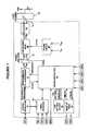
- FIG. 1is a functional block diagram illustrating an example of a low power ISM band Frequency Shift Keying (FSK) transmitter 10 suitable for application of the present invention.
- the transmitter 10is a direct FSK modulated transmitter designed to comply with the applicable FCC and ETSI standards.
- the transmitter 10is configured to support a wide range of operating bands, such as 915 MHz, 868 Mhz, 433 MHz, and 315 MHz. In each frequency band, the transmitter 10 may be programmed digitally. For multi-channel or frequency-hopping applications, the frequency of the transmitter 10 may be changed under the control a microcontroller 16 , as discussed further below.
- the FSK transmitterincludes a small loop antenna 52 , which is either a closed or open antenna, that is coupled to a package contact 54 , such as a pad or pin.
- the antenna 52is also coupled a capacitance bank 56 and the antenna 52 , package contact 54 and capacitance bank 56 combine to form a complete resonator.
- a power amplifier 12 of the transmitter 10has an open-collector differential output to drive the antenna 52 with a programmable output level controlled by microcontroller 16 .
- a programmable phase-lock-loop (PLL) synthesizer 14is coupled to power amplifier 12 and determines the carrier frequency of the transmitter.
- the carrier frequencyis synthesized from a reference frequency provided by an on-chip crystal controlled reference oscillator 18 .
- the PLL synthesizer 14allows the usage of multiple channels in any of the bands.
- the FSK deviationis selectable to accommodate various bandwidth, data rate and crystal tolerance requirements and it is also high accurate due to the direct close-loop modulation of the PLL 14 .
- Microcontroller 16performs the overall control functions associated with the operation of the transmitter 10 .
- Microcontroller 16receives a series of digital inputs from a three-wire serial interface 26 to allow a user to select, for example, the operating frequency band and the center frequency of the PLL synthesizer 14 , the polarity and deviation of the FSK modulation and the output level to drive the small loop antenna 52 .
- data bits on pin SDIare shifted into the microcontroller upon rising edge of the clock on pin SCK when the chip select pin SEL is low.
- External capacitor C 1is a fixed capacitance that is part of the resonant circuit and may be selected in order to determine the frequency band of the transmitter.
- External capacitor C 2is a fixed capacitance that is not part of the resonant circuit and is typically included to ensure an AC ground connection.
- the on-chip digital controllerallows the transmitter 10 to directly interface a serial electrically erasable programmable read-only memory (EEPROM).
- EEPROMelectrically erasable programmable read-only memory
- the different wake-up eventswill initiate automatic readout of the assigned command sequence from the memory. All settings and the transmitted code can be programmed without the use of a microcontroller 16 .
- FIG. 2is a functional block diagram illustrating an embodiment of an automatic antenna tuning circuit according to the present invention.
- the tuning circuit 50controls capacitive bank 56 in response to an input voltage V IN input to power amplifier 12 and the resonant voltage V RES at the input to capacitance bank 56 .
- the capacitive bank 56combines with the loop antenna 52 and the pad and package parasitics 54 to form a resonant circuit.
- Tuning circuit 50includes a pair of phase shifters 58 and 60 and a mixer 62 .
- Phase shifter 58shifts a phase of the resonant voltage V RES by ⁇ degrees to produce voltage signal V 1 .
- phase shifter 60shifts a phase of the input voltage V IN by ⁇ -90 degrees to produce voltage signal V 2 .
- V 1 and V 2are input to mixer 62 to produce error voltage signal V ERR .
- the error voltage signal V ERRis then input to a compare and control circuit.
- the compare and control circuitryis configured to generate a control signal that adjusts the capacitance of the capacitive bank based upon the V ERR and V IN signals, thus forming a feedback control loop.
- the compare and control logicis composed of comparators 64 and 66 , combinational control logic 64 , and a 4-bit counter 70 .
- mixer 62in the tuning control circuit 50 exploits an inherent property of mixers: if signal with identical frequencies are mixed, then the resulting DC voltage is related to the phase difference of the input signals.
- the DC output voltage from the mixere.g. V ERR , is zero if the input signals different by 90 degrees, e.g. in quadrature.
- the voltage signals V 1 and V 2must be placed in quadrature to one another through phase shifting in order to take advantage of this inherent property of mixers.
- V INis phase shifted by ⁇ 90 degrees to produce voltage signal V 2 that is in quadrature with V 1 .
- the mixer 62is realized as a standard Gilbert-Cell.
- V 1 and V 2may have a 90 degree phase difference, e.g. a quadrature relationship, when V RES and V IN (i.e. I ANT and V RES ) are in-phase.
- the phase shifters 58 and 60may be realized as. multi-section R/C and C/R dividers to provide a wide operating frequency range.
- the ⁇ -degree phase shifter 58may be zero degrees.
- the compare and control logicmonitors error voltage V ERR and, responsive thereto, increments or decrements counter 70 in order to generate a control word C ⁇ 0:3> that drives capacitance bank 56 .
- two comparators 64 and 66compare the DC error voltage V ERR from the mixer output 62 to predetermined comparison voltage levels +dV and ⁇ dV in order to generate out-of-tune signals that indicate that the resonant circuit is sufficiently out of tune to require correction.
- the output signals of the comparatorsdetermine the state of the UP and DOWN signals generated by the combinational logic circuit 68 , as illustrated in the following table: Com- parator Comparator Counter V ERR 64 66 UP DOWN change V ERR ⁇ ⁇ dV Low Low High Low +1 ⁇ dV ⁇ V ERR ⁇ +dV Low High Low Low 0 V ERR > +dV High High Low High ⁇ 1
- counter 70increases the value of the C ⁇ 0:3> digital control word. If the error voltage V ERR is above +dV, then counter 70 decreases the value of the C ⁇ 0:3> digital control word. If the error voltage is between the limits of +dV and ⁇ dV, then the value of the digital control word will not change. Thus, the counter will never overflow, i.e. if it reaches 15 it will stay there as long as a decrease is not requested. Likewise, if counter 70 reaches 0, then it will stay at that value so long as an increase is not requested.
- a 4-bit counter 70is utilized as a control word generator to generate a 4-bit digital control word C ⁇ 0:3>, where counter 70 is running from a divided system clock signal such as 10/8 MHz.
- the number of bits in the counter and in the control wordmay be varied to meet the requirements of the particular application or implementation, e.g. an n-bit counter is used to implement an n-bit control word C ⁇ 0:n ⁇ 1>. If the error voltage V ERR is within the predetermined range ⁇ dV, then the transmitter circuit is in a “well tuned condition” and the value of the digital control word for the capacitance bank 56 remains stable, e.g. 0.
- FIGS. 3 A-Billustrate one embodiment of a capacitance bank 56 and a capacitance cell 82 for use with the present invention.
- capacitance bank 56includes groups of capacitance cells, e.g. capacitance cell 82 , where the number of cells in each group is determined, in this embodiment, by exponential progression corresponding to the order of the control bit of the control word that drives the group.
- Other schemessuch as a linear increase obtained using individual capacitance cells and a shift register to generate the control word, may be possible depending upon the requirements of the particular application.
- FIG. 3Billustrates an embodiment of a capacitance cell 82 of the capacitance bank 56 of FIG. 3A .
- Capacitance cell 82has two capacitances C 1 and C 2 and switching MOS transistors NMOS 1 and NMOS 2 .
- the resulting capacitance cell 82is able to operate at low power supply levels, which may increase the tuning range and increase the amplitude available for the output signal of the transmitter. Because, in the embodiment shown, the power amplifier 12 and the loop antenna 52 are symmetrical circuits, the capacitance cell 82 may be implemented as a symmetrical circuit.
- the capacitance cell 82consists of two states: ON and OFF states. During ON state the cell 82 provides a high capacitance value and may result a low capacitance value while in the OFF state.
- the OFF state capacitanceis determined by the size of the switching MOS transistors NMOS 1 and NMOS 2 . Due to the parasitic drain-bulk and drain-gate capacitances in series with the main capacitors, the OFF state capacitance is obtained. As the MOS transistors NMOS 1 and NMOS 2 get smaller, then the OFF state capacitance may be smaller and larger ON/OFF capacitance ratio may be obtained.
- the quality factor of the capacitance cell 82may be determined by the on resistance of the MOS transistor NMOS 1 , which is lower with larger devices.
- the size of the MOS deviceis therefore selected to keep both the quality factor and the ON/OFF capacitance ratio high.
- variable capacitorsmay be used instead of the capacitance cell 82 .
- varactorsmay not operate at low power supply levels, which may reduce the tuning voltage of the capacitance bank using varactors.
- the use of varactorsmay also limit the allowed signal amplitude due to the large AC amplitude that may result from a forward biased condition on the DC-wise reverse biased varactors.
- the continuous operation and the several states of the capacitance bank 56allow a fast reaction to any changes during transmission with small steps in the whole resonant system. Having small capacitance steps provided by the capacitance bank 56 the tuning of a resonant circuitry gets even with high quality factor.
- the number of the necessary ON state capacitance cellsis defined by the value of the C ⁇ 0:n ⁇ 1> control word, which is updated continuously during transmission in order to minimize the error signal V ERR . If the operating frequency changes, or any detuning effect occurs during operation, then the tuning control circuit automatically follows the changes and maintains the resonance of the transmitter at the desired frequency.
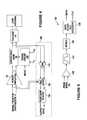
- FIG. 4is a functional block diagram illustrating an embodiment of a receiver portion for a transceiver circuit according to the present invention.
- the receiver circuit 100is electrically coupled to loop antenna 52 through the packaging for a transceiver circuit that includes the transmitter discussed above with regard to FIGS. 1-3 .
- tuning circuit 150is adapted to hold the control word value C ⁇ 0:3> that is input to capacitance bank 56 responsive to a MODE signal.
- Tuning circuit 150may be adapted in a number of ways to hold the control word value derived during a transmit cycle of the transceiver.
- the up/down counter 70 of FIG. 2may be adapted to block the CLK signal or halt the increment/decrement function.
- a registermay be provided that latches the control word value responsive to the MODE signal.
- the MODE signalmay be generated by internal controller 16 or by an external controller. Also, during a receive mode cycle, power amplifier 12 may be turned off so that no transmit signal is produced by the transmitter circuit, which may also be achieved responsive to the MODE signal.
- the timing of the MODE signalis such that the control word value C ⁇ 0:3> derived during the transmit cycle, when a high amplitude signal is present that is suitable for the automatic resonance tuning described above to take place, is captured and maintained during the receive mode to substantially maintain the resonance of the loop antenna.
- the receiver 100includes a low noise amplifier (LNA) 110 whose inputs are electrically coupled to the loop antenna.
- LNAlow noise amplifier
- the output of amplifier 110is input to receiver mixer 120 along with the output signal from synthesizer 14 of FIG. 1 .
- Receive mixer 120down converts the amplified radio frequency (RF) signal from LNA 110 to a base band frequency using a local oscillator signal that is obtained from synthesizer 14 .
- the down converted signal from mixer 120is input to base band blocks 130 , which decode and recover the received data signal.
- the received datamay be output from the transceiver circuit through interface circuitry for the transceiver similar to the three wire interface shown in FIG. 1 .
- FIG. 5illustrates an example of the base band circuitry 130 for a frequency shift keyed (FSK) receiver.
- the example of FIG. 5includes an amplifier 132 that receives the signal output from receive mixer 120 , buffers the output from the mixer, and outputs the buffered signal to a filter 134 .
- the filtered signalis output to demodulator 136 and then passes into a data filter and clock recovery circuit 138 to recover the data and clock signals from the received signal.
- a control value for antenna resonance tuning derived during a transmit cycle of a transceiveris maintained during a receive cycle of the transceiver in order to maintain antenna resonance.
Landscapes
- Engineering & Computer Science (AREA)
- Computer Networks & Wireless Communication (AREA)
- Signal Processing (AREA)
- Transmitters (AREA)
Abstract
Description
- This patent application is a continuation-in-part of co-pending, commonly assigned, U.S. patent application Ser. No. 10/286,647, filed Nov. 1, 2002.
- The present invention relates to transceiver circuits. More specifically, it relates to automatic tuning of an integrated loop antenna system of a transceiver circuit.
- A generally license free frequency band called the industrial-scientific-medical (ISM) band has emerged for short range low power applications, such as industrial controls, telemetry and low power data transmission. A range of frequencies from 300 MHz to 1 Ghz is generally provided for ISM. For example, the European ISM standard provides for operation at 433 MHz and at frequencies ranging from 800 MHz to 930 MHz. The US ISM standard provides for a band at 300 MHz and in a range from 902 MHz to 928 MHz. An ISM transceiver may, therefore, need to operate at more than one carrier frequency. The transceiver's carrier frequency fc is typically determined by a reference frequency fref from a reference crystal. A range of carrier frequency values, e.g. ranging from 800 MHz to 930 MHz, can be achieved by synthesizing the carrier frequency from the reference frequency to obtain the carrier frequency. For example, a phased-lock-loop (PLL) synthesizer may be used to synthesize the carrier frequency from the reference frequency.
- Examples of applications for ISM transmitters include: security alarms, telemetry, environment control systems, wireless data repeaters, personal/patient data logging, access and movement monitoring, remote metering, barcode readers, wireless keyboard and mouse, remote keyless entry, remote tire pressure control, garage door openers, and doorbells. Many of these examples may include bi-directional data communication, where a transceiver is useful.
- U.S. Pat. No. 6,253,068 issued on Jun. 26, 2001 to Elder et al. discloses an example of a fully integrated all-CMOS AM transmitter with automatic antenna tuning. In the disclosed system, the antenna serves as a resonator for the oscillator block within the phase-lock-loop (PLL). By using the antenna as the resonator, Elder et al. automatically provides that a tuning varactor in the resonant circuitry to receive the proper tuning voltage in order to tune the antenna (VCO resonator) to the desired frequency. However, since continuous tuning is necessary for the PLL, only varactors can be used, which require higher voltage levels that place a relatively high minimum limit on the supply voltage and the signal amplitude on the antenna. Further, any mistuning effects that may occur due to the antenna may cause the oscillator to fall out of the tuning range of the PLL thereby disrupting oscillation and causing the circuit to cease functioning.
- U.S. Pat. Nos. 5,136,719 and 5,483,688 describe an approach for antenna tuning that works for small signals that are suitable for use in receiver circuits rather than transmitter circuits. The tuning elements used in these patents are varactors, which require a relatively high minimum supply voltage because a decoupling capacitor is required in order to control the tuning elements.
- U.S. Pat. No. 5,136,719 issued on Aug. 4, 1992 to Gaskill et al. discloses another automatic antenna tuning method and apparatus. In Gaskill et al. system, an antenna receives radio frequency signals in a desired reception band from 88 to 108 MHz. The antenna is automatically tuned to receive packets of information on a periodic basis. During a tuning mode, the control circuit sweeps a varactor biasing voltage over its full range to measure an optimum level. To determine the optimum tuning condition, a control circuit receives from a receiver subsystem a Received Signal Strength Indicator (RSSI) signal that is indicative of received signal strength. Once the sweep is concluded, the system sets the tuning element, and hence the antenna, to the value that produced the maximum RSSI signal. A packet of information is then received and passed to a protocol decoder to decode the information. The method of Gaskill et al., however, the antenna tuning approach lacks an adaptive capability with respect to changes in the device environment or in component selection. Further, overall system requirements typically impose certain time limitations on the time available for the antenna tuning procedure, which therefore impose limitations on the accuracy of the antenna tuning procedure as set forth under the Gaskill method.
- U.S. Pat. No. 5,483,688 issued on Jan. 9, 1996 to English et al. discloses still another method and apparatus for automatically tuning an adaptive antenna. A predictor value is used to establish an antenna tuning voltage sub-range that is most likely to contain the optimum antenna tuning voltage, where the sub-range is a smaller range than the full antenna tuning voltage range. The antenna tuning voltage sub-range is then traversed while monitoring a signal strength indicator to identify an antenna tuning voltage providing optimum tuning conditions, which improves the execution time and accuracy of the antenna tuning.
- Another approach to antenna tuning is found in the ASCell3913 868 MHz, 433 MHz and 315 MHz ISM Band FSK Transmitter from Austria Micro Systems (AMS). (See the ASCell3913 Preliminary Data Sheet, Rev. No. D5, March 2002, incorporated by reference in its entirety.) The ASCell3913 solution uses three capacitance values to tune an antenna. Antenna tuning is allowed for only a short period when the transmitter is powered-up. The resulting state of the tuning circuit is maintained for the duration of the transmission session. This solution has a limited accuracy due to the reduced number of capacitance cells and cannot follow changes in conditions that may occur during long transmission periods.
- The present invention is directed towards to a method and apparatus for tuning an integrated loop antenna tuning system in a transceiver that may operate under low operating voltage supply levels and with a high output signal level.
- An embodiment of a transceiver circuit, according to the present invention, has a transmitter circuit, a receiver circuit, and an automatic tuning circuit, where the transmitter circuit includes a power amplifier. In this embodiment, the automatic tuning circuit includes a capacitance bank coupled between the power amplifier and a package connection for connecting to a resonant circuit that includes an antenna. The capacitance bank has an input that is coupled to an output of the power amplifier, an output that is coupled to the resonant circuit, and a control input, where a capacitance of the capacitance bank is determined by a control word received at the control input. The automatic tuning circuit also includes a tuning circuit having a first input for receiving a first voltage present at the inputs of the power amplifier, a second input for receiving a second voltage present across the capacitance bank, a mode input for receiving a mode signal, and an output for generating the control word responsive to the first and second voltages. The tuning circuit is further configured to hold constant the value of the control word responsive to the mode signal, where the mode signal corresponds to a receive mode.
- An embodiment of a method, according to the present invention, for automatically tuning a resonant circuit that includes an antenna, the resonant circuit being part of transceiver circuit that includes a receiver circuit and a transmitter circuit that includes a power amplifier for driving the resonant circuit, calls for providing an adjustable capacitance as part of the resonant circuit. The method also calls for comparing a resonance signal of the resonant circuit to an input signal to the power amplifier in order to generate a control word signal for controlling the adjustable capacitance and varying the adjustable capacitance responsive to the control word signal in order to tune the resonant circuit during a transmit mode. Finally, the method sets forth maintaining a constant value for the control word signal responsive to a mode signal corresponding to a receive mode of the transceiver.
- The present invention is described herein with reference to the accompanying drawings, in which like numerals designate corresponding parts in the figures, wherein:
FIG. 1 is a functional block diagram illustrating an example of a low power ISM band Frequency Shift Keying (FSK) transmitter suitable for application of the present invention;FIG. 2 is a functional block diagram illustrating an embodiment of an antenna tuning circuit according to the present invention;FIG. 3A is a functional block diagram illustrating an embodiment of the capacitance bank ofFIG. 2 ;FIG. 3B is a circuit diagram illustrating an embodiment of a capacitance cell of the capacitance bank ofFIG. 3A ;FIG. 4 is a functional block diagram illustrating an embodiment of a receiver portion for a transceiver circuit according to the present invention; andFIG. 5 is a functional block diagram illustrating one example of the receiver base band circuitry ofFIG. 4 .- The present invention is directed toward a method and apparatus for tuning small resonant loop antennas in transceiver circuits.
- To minimize the current consumption, external component count and size of an RF transmitter it is desirable to directly drive an integrated loop antenna having high input impedance. Small loop antennas need tuning capacitance to obtain antenna resonance at a desired operating frequency in order to improve radiation efficiency. The desired resonant frequency for a circuit may be affected by variations in integrated circuit processes, circuit packaging, and PCB manufacturing tolerances.
- The antenna tuning circuit and method of the present invention identifies a de-tuned condition and acts in order to minimize the detuning. The present invention works on the principle that, when in resonance, the resonant voltage (Vres) and antenna current (Iant) on the complete resonator (antenna, package, plus tuning capacitance) are in phase. If a phase shift is observed, then an error signal (proportional to the phase error) is generated. The error signal is evaluated by a control circuit, which controls the tuning capacitance in response to the error signal. The tuning capacitance is provided by a capacitance bank that operates as a load on the loop antenna
FIG. 1 is a functional block diagram illustrating an example of a low power ISM band Frequency Shift Keying (FSK) transmitter10 suitable for application of the present invention. The transmitter10 is a direct FSK modulated transmitter designed to comply with the applicable FCC and ETSI standards. The transmitter10 is configured to support a wide range of operating bands, such as 915 MHz, 868 Mhz, 433 MHz, and 315 MHz. In each frequency band, the transmitter10 may be programmed digitally. For multi-channel or frequency-hopping applications, the frequency of the transmitter10 may be changed under the control amicrocontroller 16, as discussed further below.- In.
FIG. 1 , the FSK transmitter includes asmall loop antenna 52, which is either a closed or open antenna, that is coupled to apackage contact 54, such as a pad or pin. Theantenna 52 is also coupled acapacitance bank 56 and theantenna 52,package contact 54 andcapacitance bank 56 combine to form a complete resonator. Apower amplifier 12 of the transmitter10 has an open-collector differential output to drive theantenna 52 with a programmable output level controlled bymicrocontroller 16. - A programmable phase-lock-loop (PLL)
synthesizer 14 is coupled topower amplifier 12 and determines the carrier frequency of the transmitter. The carrier frequency is synthesized from a reference frequency provided by an on-chip crystal controlledreference oscillator 18. ThePLL synthesizer 14 allows the usage of multiple channels in any of the bands. The FSK deviation is selectable to accommodate various bandwidth, data rate and crystal tolerance requirements and it is also high accurate due to the direct close-loop modulation of thePLL 14. Microcontroller 16 performs the overall control functions associated with the operation of the transmitter10.Microcontroller 16 receives a series of digital inputs from a three-wireserial interface 26 to allow a user to select, for example, the operating frequency band and the center frequency of thePLL synthesizer 14, the polarity and deviation of the FSK modulation and the output level to drive thesmall loop antenna 52. In this example, data bits on pin SDI are shifted into the microcontroller upon rising edge of the clock on pin SCK when the chip select pin SEL is low. External capacitor C1 is a fixed capacitance that is part of the resonant circuit and may be selected in order to determine the frequency band of the transmitter. External capacitor C2 is a fixed capacitance that is not part of the resonant circuit and is typically included to ensure an AC ground connection.- In simple applications, the on-chip digital controller allows the transmitter10 to directly interface a serial electrically erasable programmable read-only memory (EEPROM). The different wake-up events will initiate automatic readout of the assigned command sequence from the memory. All settings and the transmitted code can be programmed without the use of a
microcontroller 16. FIG. 2 is a functional block diagram illustrating an embodiment of an automatic antenna tuning circuit according to the present invention. Thetuning circuit 50 controls capacitivebank 56 in response to an input voltage VINinput topower amplifier 12 and the resonant voltage VRESat the input tocapacitance bank 56. As noted above, thecapacitive bank 56 combines with theloop antenna 52 and the pad and package parasitics54 to form a resonant circuit.Tuning circuit 50 includes a pair ofphase shifters mixer 62.Phase shifter 58 shifts a phase of the resonant voltage VRESby Φ degrees to produce voltage signal V1. Likewise,phase shifter 60 shifts a phase of the input voltage VINby Φ-90 degrees to produce voltage signal V2. V1and V2are input tomixer 62 to produce error voltage signal VERR. The error voltage signal VERRis then input to a compare and control circuit. The compare and control circuitry is configured to generate a control signal that adjusts the capacitance of the capacitive bank based upon the VERRand VINsignals, thus forming a feedback control loop. In one embodiment, the compare and control logic is composed ofcomparators combinational control logic 64, and a 4-bit counter 70.- The use of
mixer 62 in thetuning control circuit 50 exploits an inherent property of mixers: if signal with identical frequencies are mixed, then the resulting DC voltage is related to the phase difference of the input signals. The DC output voltage from the mixer, e.g. VERR, is zero if the input signals different by 90 degrees, e.g. in quadrature. The voltage signals V1and V2must be placed in quadrature to one another through phase shifting in order to take advantage of this inherent property of mixers. In this embodiment, VINis phase shifted by Φ±90 degrees to produce voltage signal V2that is in quadrature with V1. As is well understood in the art, other combinations of phase shifts may be used to place V1and V2in quadrature with one another. In one embodiment of the present invention, themixer 62 is realized as a standard Gilbert-Cell. - Since the current in the resonant loop IANTis in-phase with the input voltage of the power amplifier VIN, the phases of VRESand VINare evaluated. To obtain a zero error voltage VERRat the
mixer output 62 when VRESand VINare in-phase, a 90 degree relative phase difference must be implemented usingphase shifters - The
phase shifters degree phase shifter 58 may be zero degrees. For the protection of circuitry, however, a phase shift of Φ=45 degrees may also be a suitable selection for certain embodiments of the present invention. The compare and control logic monitors error voltage VERRand, responsive thereto, increments or decrements counter70 in order to generate a control word C<0:3> that drivescapacitance bank 56. In one embodiment of the invention, twocomparators mixer output 62 to predetermined comparison voltage levels +dV and −dV in order to generate out-of-tune signals that indicate that the resonant circuit is sufficiently out of tune to require correction. The output signals of the comparators determine the state of the UP and DOWN signals generated by thecombinational logic circuit 68, as illustrated in the following table:Com- parator Comparator Counter V ERR 64 66 UP DOWN change VERR< −dV Low Low High Low +1 −dV < VERR< +dV Low High Low Low 0 VERR> +dV High High Low High −1 - If the error voltage VERRis below −dV, then counter70 increases the value of the C<0:3> digital control word. If the error voltage VERRis above +dV, then counter70 decreases the value of the C<0:3> digital control word. If the error voltage is between the limits of +dV and −dV, then the value of the digital control word will not change. Thus, the counter will never overflow, i.e. if it reaches 15 it will stay there as long as a decrease is not requested. Likewise, if
counter 70reaches 0, then it will stay at that value so long as an increase is not requested. - In the embodiment shown in
FIG. 2 , a 4-bit counter 70 is utilized as a control word generator to generate a 4-bit digital control word C<0:3>, wherecounter 70 is running from a divided system clock signal such as 10/8 MHz. The number of bits in the counter and in the control word may be varied to meet the requirements of the particular application or implementation, e.g. an n-bit counter is used to implement an n-bit control word C<0:n−1>. If the error voltage VERRis within the predetermined range ±dV, then the transmitter circuit is in a “well tuned condition” and the value of the digital control word for thecapacitance bank 56 remains stable, e.g. 0. If the error voltage falls below −dV, then the UP signal becomes active and counter70 increases the value of the digital control word C<0:3> to +1. On the other hand, if the error voltage goes above +dV, then the DOWN signal becomes active and counter70 decreases the value of the C<0:3> digital control word to −1, e.g. 15. Using a divided system clock signal to drive thecounter 70 provides a refractory time period for the transmitter circuit to settle any transients caused by a change in the state ofcapacitor bank 56 so that the control loop remains stabilized and does not attempt to respond to the transients. - FIGS.3A-B illustrate one embodiment of a
capacitance bank 56 and acapacitance cell 82 for use with the present invention. In the embodiment ofFIG. 3A ,capacitance bank 56 includes groups of capacitance cells,e.g. capacitance cell 82, where the number of cells in each group is determined, in this embodiment, by exponential progression corresponding to the order of the control bit of the control word that drives the group. Thus, in this embodiment, control word bit C<0> drives a single cell, e.g. 20=1. Control word bit C<1> drives two cells, e.g. 20=2. Control word bit C<2> drives four cells, e.g. 22=4. Control word bit C<3> drives eight cells, e.g. 23=8. Other schemes, such as a linear increase obtained using individual capacitance cells and a shift register to generate the control word, may be possible depending upon the requirements of the particular application. FIG. 3B illustrates an embodiment of acapacitance cell 82 of thecapacitance bank 56 ofFIG. 3A .Capacitance cell 82 has two capacitances C1 and C2 and switching MOS transistors NMOS1 and NMOS2. The resultingcapacitance cell 82 is able to operate at low power supply levels, which may increase the tuning range and increase the amplitude available for the output signal of the transmitter. Because, in the embodiment shown, thepower amplifier 12 and theloop antenna 52 are symmetrical circuits, thecapacitance cell 82 may be implemented as a symmetrical circuit.- The
capacitance cell 82 consists of two states: ON and OFF states. During ON state thecell 82 provides a high capacitance value and may result a low capacitance value while in the OFF state. The OFF state capacitance is determined by the size of the switching MOS transistors NMOS1 and NMOS2. Due to the parasitic drain-bulk and drain-gate capacitances in series with the main capacitors, the OFF state capacitance is obtained. As the MOS transistors NMOS1 and NMOS2 get smaller, then the OFF state capacitance may be smaller and larger ON/OFF capacitance ratio may be obtained. During the ON state, the quality factor of thecapacitance cell 82 may be determined by the on resistance of the MOS transistor NMOS1, which is lower with larger devices. The size of the MOS device is therefore selected to keep both the quality factor and the ON/OFF capacitance ratio high. - Instead of the
capacitance cell 82, variable capacitors (varactors) may be used. However, varactors may not operate at low power supply levels, which may reduce the tuning voltage of the capacitance bank using varactors. In addition, the use of varactors may also limit the allowed signal amplitude due to the large AC amplitude that may result from a forward biased condition on the DC-wise reverse biased varactors. - The continuous operation and the several states of the
capacitance bank 56 allow a fast reaction to any changes during transmission with small steps in the whole resonant system. Having small capacitance steps provided by thecapacitance bank 56 the tuning of a resonant circuitry gets even with high quality factor. The number of the necessary ON state capacitance cells is defined by the value of the C<0:n−1> control word, which is updated continuously during transmission in order to minimize the error signal VERR. If the operating frequency changes, or any detuning effect occurs during operation, then the tuning control circuit automatically follows the changes and maintains the resonance of the transmitter at the desired frequency. FIG. 4 is a functional block diagram illustrating an embodiment of a receiver portion for a transceiver circuit according to the present invention. Thereceiver circuit 100 is electrically coupled toloop antenna 52 through the packaging for a transceiver circuit that includes the transmitter discussed above with regard toFIGS. 1-3 . In this example, tuningcircuit 150 is adapted to hold the control word value C<0:3> that is input tocapacitance bank 56 responsive to a MODE signal.Tuning circuit 150 may be adapted in a number of ways to hold the control word value derived during a transmit cycle of the transceiver. For example, the up/down counter70 ofFIG. 2 may be adapted to block the CLK signal or halt the increment/decrement function. By way of another example, a register may be provided that latches the control word value responsive to the MODE signal.- The MODE signal may be generated by
internal controller 16 or by an external controller. Also, during a receive mode cycle,power amplifier 12 may be turned off so that no transmit signal is produced by the transmitter circuit, which may also be achieved responsive to the MODE signal. The timing of the MODE signal is such that the control word value C<0:3> derived during the transmit cycle, when a high amplitude signal is present that is suitable for the automatic resonance tuning described above to take place, is captured and maintained during the receive mode to substantially maintain the resonance of the loop antenna. - Further, in the example of
FIG. 4 , thereceiver 100 includes a low noise amplifier (LNA)110 whose inputs are electrically coupled to the loop antenna. The output ofamplifier 110 is input toreceiver mixer 120 along with the output signal fromsynthesizer 14 ofFIG. 1 . Receivemixer 120 down converts the amplified radio frequency (RF) signal fromLNA 110 to a base band frequency using a local oscillator signal that is obtained fromsynthesizer 14. The down converted signal frommixer 120 is input to base band blocks130, which decode and recover the received data signal. The received data may be output from the transceiver circuit through interface circuitry for the transceiver similar to the three wire interface shown inFIG. 1 . FIG. 5 illustrates an example of thebase band circuitry 130 for a frequency shift keyed (FSK) receiver. The example ofFIG. 5 includes anamplifier 132 that receives the signal output from receivemixer 120, buffers the output from the mixer, and outputs the buffered signal to afilter 134. The filtered signal is output to demodulator136 and then passes into a data filter andclock recovery circuit 138 to recover the data and clock signals from the received signal. One of ordinary skill in the art will readily appreciate that many different types of receiver circuits may be used depending upon the desired application and that different types of receivers will have different base band circuitry components. The use of different receiver circuits does not depart from this aspect of the present invention, wherein a control value for antenna resonance tuning derived during a transmit cycle of a transceiver is maintained during a receive cycle of the transceiver in order to maintain antenna resonance.- In view of the wide variety of embodiments to which the principles of the present invention can be applied, it should be understood that the illustrated embodiments are exemplary only, and should not be taken as limiting the scope of the present invention. For example, a variety of circuit elements may be utilized to perform certain functions of the present invention. Also, the function of some circuit elements may be combined into a single device while the function of other circuit elements may be implemented so as to be performed by multiple devices. Further, the tuning control circuit and method of the present invention may be applied to a variety of transceiver types where resonance control is advantageous.
Claims (17)
Priority Applications (1)
| Application Number | Priority Date | Filing Date | Title |
|---|---|---|---|
| US10/891,708US7190933B2 (en) | 2002-11-01 | 2004-07-15 | Method and apparatus for automatic tuning of a resonant loop antenna in a transceiver circuit |
Applications Claiming Priority (2)
| Application Number | Priority Date | Filing Date | Title |
|---|---|---|---|
| US10/286,647US7058372B1 (en) | 2002-11-01 | 2002-11-01 | Method and apparatus for automatic tuning of a resonant loop antenna |
| US10/891,708US7190933B2 (en) | 2002-11-01 | 2004-07-15 | Method and apparatus for automatic tuning of a resonant loop antenna in a transceiver circuit |
Related Parent Applications (1)
| Application Number | Title | Priority Date | Filing Date |
|---|---|---|---|
| US10/286,647Continuation-In-PartUS7058372B1 (en) | 2002-11-01 | 2002-11-01 | Method and apparatus for automatic tuning of a resonant loop antenna |
Publications (2)
| Publication Number | Publication Date |
|---|---|
| US20050003771A1true US20050003771A1 (en) | 2005-01-06 |
| US7190933B2 US7190933B2 (en) | 2007-03-13 |
Family
ID=46302343
Family Applications (1)
| Application Number | Title | Priority Date | Filing Date |
|---|---|---|---|
| US10/891,708Expired - LifetimeUS7190933B2 (en) | 2002-11-01 | 2004-07-15 | Method and apparatus for automatic tuning of a resonant loop antenna in a transceiver circuit |
Country Status (1)
| Country | Link |
|---|---|
| US (1) | US7190933B2 (en) |
Cited By (26)
| Publication number | Priority date | Publication date | Assignee | Title |
|---|---|---|---|---|
| WO2006118639A3 (en)* | 2005-04-28 | 2007-10-25 | Comsonics Inc | Antenna for cable ingress/egress management signaling |
| US20080058902A1 (en)* | 2006-04-07 | 2008-03-06 | Biophan Technologies, Inc. | Resonance tuning module for implantable devices and leads |
| WO2007118194A3 (en)* | 2006-04-07 | 2008-08-07 | Biophan Technologies Inc | Resonance circuit for implantable devices and leads |
| US20080200134A1 (en)* | 2007-02-15 | 2008-08-21 | Infineon Technologies Ag | Transmitter circuit |
| US20080227408A1 (en)* | 2007-03-16 | 2008-09-18 | Advanced Connectek Inc. | Apparatus and method for switching frequency band of antenna |
| USRE40620E1 (en)* | 1997-05-09 | 2009-01-06 | Micrel, Inc. | Fully integrated All-CMOS AM transmitter with automatic antenna tuning |
| US20090130997A1 (en)* | 2006-07-13 | 2009-05-21 | Freescale Semiconductor, Inc. | Transmitting device and method of tuning the transmitting device |
| NL2002596C2 (en)* | 2009-03-06 | 2010-09-07 | Nedap Nv | ANTENNA UNIT WITH AUTOMATIC TUNING. |
| US20100256831A1 (en)* | 2009-04-03 | 2010-10-07 | Keith Abramo | Wireless power infrastructure |
| US20120238210A1 (en)* | 2011-03-18 | 2012-09-20 | Symbol Technologies, Inc. | Close proximity antenna measurement and tuning |
| US20140159935A1 (en)* | 2012-12-05 | 2014-06-12 | Nxp B.V. | Concurrent multiband transceiver |
| WO2014184676A3 (en)* | 2013-04-15 | 2015-03-05 | Schrader Electronics Limited | Multi-frequency tire pressure monitoring detector |
| WO2015195403A1 (en)* | 2014-06-19 | 2015-12-23 | Triune Ip Llc | Galvanically isolated switch system |
| GB2529887A (en)* | 2014-09-05 | 2016-03-09 | Smart Antenna Technologies Ltd | Tuning reconfigurable multi-port antennas |
| US9991597B2 (en) | 2015-03-11 | 2018-06-05 | Nxp B.V. | Impedance tuning circuit |
| JP2019135795A (en)* | 2008-02-28 | 2019-08-15 | ペレグリン セミコンダクター コーポレーション | Method and apparatus used when capacitor is synchronized by digital processing in integrated circuit element |
| US11749893B2 (en) | 2016-08-29 | 2023-09-05 | Silicon Laboratories Inc. | Apparatus for antenna impedance-matching and associated methods |
| US11750167B2 (en) | 2017-11-27 | 2023-09-05 | Silicon Laboratories Inc. | Apparatus for radio-frequency matching networks and associated methods |
| US11764473B2 (en) | 2016-08-29 | 2023-09-19 | Silicon Laboratories Inc. | Apparatus with partitioned radio frequency antenna and matching network and associated methods |
| US11764749B2 (en) | 2016-08-29 | 2023-09-19 | Silicon Laboratories Inc. | Apparatus with partitioned radio frequency antenna and matching network and associated methods |
| US11769949B2 (en) | 2016-08-29 | 2023-09-26 | Silicon Laboratories Inc. | Apparatus with partitioned radio frequency antenna and matching network and associated methods |
| US11862872B2 (en) | 2021-09-30 | 2024-01-02 | Silicon Laboratories Inc. | Apparatus for antenna optimization and associated methods |
| US11894621B2 (en) | 2017-12-18 | 2024-02-06 | Silicon Laboratories Inc. | Radio-frequency apparatus with multi-band balun with improved performance and associated methods |
| US11894826B2 (en) | 2017-12-18 | 2024-02-06 | Silicon Laboratories Inc. | Radio-frequency apparatus with multi-band balun and associated methods |
| US11894622B2 (en) | 2016-08-29 | 2024-02-06 | Silicon Laboratories Inc. | Antenna structure with double-slotted loop and associated methods |
| US11916514B2 (en) | 2017-11-27 | 2024-02-27 | Silicon Laboratories Inc. | Radio-frequency apparatus with multi-band wideband balun and associated methods |
Families Citing this family (22)
| Publication number | Priority date | Publication date | Assignee | Title |
|---|---|---|---|---|
| US7137980B2 (en) | 1998-10-23 | 2006-11-21 | Sherwood Services Ag | Method and system for controlling output of RF medical generator |
| AU2004235739B2 (en) | 2003-05-01 | 2010-06-17 | Covidien Ag | Method and system for programming and controlling an electrosurgical generator system |
| WO2005050151A1 (en) | 2003-10-23 | 2005-06-02 | Sherwood Services Ag | Thermocouple measurement circuit |
| US7396336B2 (en) | 2003-10-30 | 2008-07-08 | Sherwood Services Ag | Switched resonant ultrasonic power amplifier system |
| EP1610257A1 (en)* | 2004-06-23 | 2005-12-28 | St Microelectronics S.A. | Impedance matching in reader of electromagnetic transponder |
| DE602006020707D1 (en)* | 2005-04-08 | 2011-04-28 | Nxp Bv | RFID READER WITH ANTENNA AND OPERATING METHOD THEREFOR |
| US7947039B2 (en) | 2005-12-12 | 2011-05-24 | Covidien Ag | Laparoscopic apparatus for performing electrosurgical procedures |
| CA2574934C (en) | 2006-01-24 | 2015-12-29 | Sherwood Services Ag | System and method for closed loop monitoring of monopolar electrosurgical apparatus |
| US7960772B2 (en) | 2007-04-26 | 2011-06-14 | Peregrine Semiconductor Corporation | Tuning capacitance to enhance FET stack voltage withstand |
| US8262652B2 (en) | 2009-01-12 | 2012-09-11 | Tyco Healthcare Group Lp | Imaginary impedance process monitoring and intelligent shut-off |
| US9028479B2 (en) | 2011-08-01 | 2015-05-12 | Covidien Lp | Electrosurgical apparatus with real-time RF tissue energy control |
| KR101878875B1 (en)* | 2011-12-26 | 2018-07-17 | 삼성전자주식회사 | Apparatus and method for clibration of transmitter in communication device |
| US9002278B2 (en)* | 2012-02-29 | 2015-04-07 | Htc Corporation | Simple automatic antenna tuning system and method |
| US9529025B2 (en) | 2012-06-29 | 2016-12-27 | Covidien Lp | Systems and methods for measuring the frequency of signals generated by high frequency medical devices |
| US20140141738A1 (en)* | 2012-11-19 | 2014-05-22 | Rf Micro Devices, Inc. | Self-tuning amplification device |
| US9504516B2 (en) | 2013-05-31 | 2016-11-29 | Covidien LLP | Gain compensation for a full bridge inverter |
| US9872719B2 (en) | 2013-07-24 | 2018-01-23 | Covidien Lp | Systems and methods for generating electrosurgical energy using a multistage power converter |
| US9655670B2 (en) | 2013-07-29 | 2017-05-23 | Covidien Lp | Systems and methods for measuring tissue impedance through an electrosurgical cable |
| US9831857B2 (en) | 2015-03-11 | 2017-11-28 | Peregrine Semiconductor Corporation | Power splitter with programmable output phase shift |
| US11006997B2 (en) | 2016-08-09 | 2021-05-18 | Covidien Lp | Ultrasonic and radiofrequency energy production and control from a single power converter |
| US9948281B2 (en) | 2016-09-02 | 2018-04-17 | Peregrine Semiconductor Corporation | Positive logic digitally tunable capacitor |
| US12226143B2 (en) | 2020-06-22 | 2025-02-18 | Covidien Lp | Universal surgical footswitch toggling |
Citations (16)
| Publication number | Priority date | Publication date | Assignee | Title |
|---|---|---|---|---|
| US3794941A (en)* | 1972-05-08 | 1974-02-26 | Hughes Aircraft Co | Automatic antenna impedance tuner including digital control circuits |
| US4493112A (en)* | 1981-11-19 | 1985-01-08 | Rockwell International Corporation | Antenna tuner discriminator |
| US4713808A (en)* | 1985-11-27 | 1987-12-15 | A T & E Corporation | Watch pager system and communication protocol |
| US5136719A (en)* | 1988-12-05 | 1992-08-04 | Seiko Corp. | Automatic antenna tubing method and apparatus |
| US5170496A (en)* | 1989-06-22 | 1992-12-08 | Texas Instruments Deutschland Gmbh | Circuit arrangement for matching the resonant frequency of an antenna resonant circuit to the output frequency of a transmitter output stage |
| US5208537A (en)* | 1990-11-12 | 1993-05-04 | Siemens Aktiengesellschaft | Method for matching antennas in a nuclear magnetic resonance imaging apparatus |
| US5404113A (en)* | 1993-07-06 | 1995-04-04 | The Boeing Company | High efficiency power amplifier |
| US5483680A (en)* | 1994-01-07 | 1996-01-09 | Harris Corporation | Tuning method for automatic antenna couplers |
| US5483688A (en)* | 1993-01-22 | 1996-01-09 | Seiko Communications Holding N.V. | Adaptive automatic antenna tuning method and apparatus |
| US5491715A (en)* | 1993-06-28 | 1996-02-13 | Texas Instruments Deutschland Gmbh | Automatic antenna tuning method and circuit |
| US5564086A (en)* | 1993-11-29 | 1996-10-08 | Motorola, Inc. | Method and apparatus for enhancing an operating characteristic of a radio transmitter |
| US5673001A (en)* | 1995-06-07 | 1997-09-30 | Motorola, Inc. | Method and apparatus for amplifying a signal |
| US6028503A (en)* | 1996-11-05 | 2000-02-22 | U.S. Philips Corporation | Contactless data transmission and receiving device with a synchronous demodulator |
| US6253068B1 (en)* | 1997-05-09 | 2001-06-26 | Micrel, Incorporated | Fully integrated all-CMOS AM transmitter with automatic antenna tuning |
| US20030119469A1 (en)* | 2001-10-26 | 2003-06-26 | Microsoft Corporation | System and method for automatically tuning an antenna |
| US7058372B1 (en)* | 2002-11-01 | 2006-06-06 | Integration Associates Inc. | Method and apparatus for automatic tuning of a resonant loop antenna |
Family Cites Families (2)
| Publication number | Priority date | Publication date | Assignee | Title |
|---|---|---|---|---|
| US4862516A (en) | 1987-01-02 | 1989-08-29 | Motorola, Inc. | System for automatically tuning the antenna of a miniature portable communications device |
| US4817196A (en) | 1987-01-02 | 1989-03-28 | Motorola, Inc. | Apparatus for tuning the antenna of a miniature personal communications device |
- 2004
- 2004-07-15USUS10/891,708patent/US7190933B2/ennot_activeExpired - Lifetime
Patent Citations (18)
| Publication number | Priority date | Publication date | Assignee | Title |
|---|---|---|---|---|
| US3794941A (en)* | 1972-05-08 | 1974-02-26 | Hughes Aircraft Co | Automatic antenna impedance tuner including digital control circuits |
| US4493112A (en)* | 1981-11-19 | 1985-01-08 | Rockwell International Corporation | Antenna tuner discriminator |
| US4713808A (en)* | 1985-11-27 | 1987-12-15 | A T & E Corporation | Watch pager system and communication protocol |
| US5136719A (en)* | 1988-12-05 | 1992-08-04 | Seiko Corp. | Automatic antenna tubing method and apparatus |
| US5301358A (en)* | 1988-12-05 | 1994-04-05 | Seiko Corp. | Automatic antenna tuning method and apparatus |
| US5170496A (en)* | 1989-06-22 | 1992-12-08 | Texas Instruments Deutschland Gmbh | Circuit arrangement for matching the resonant frequency of an antenna resonant circuit to the output frequency of a transmitter output stage |
| US5208537A (en)* | 1990-11-12 | 1993-05-04 | Siemens Aktiengesellschaft | Method for matching antennas in a nuclear magnetic resonance imaging apparatus |
| US5483688A (en)* | 1993-01-22 | 1996-01-09 | Seiko Communications Holding N.V. | Adaptive automatic antenna tuning method and apparatus |
| US5491715A (en)* | 1993-06-28 | 1996-02-13 | Texas Instruments Deutschland Gmbh | Automatic antenna tuning method and circuit |
| US5404113A (en)* | 1993-07-06 | 1995-04-04 | The Boeing Company | High efficiency power amplifier |
| US5564086A (en)* | 1993-11-29 | 1996-10-08 | Motorola, Inc. | Method and apparatus for enhancing an operating characteristic of a radio transmitter |
| US5483680A (en)* | 1994-01-07 | 1996-01-09 | Harris Corporation | Tuning method for automatic antenna couplers |
| US5673001A (en)* | 1995-06-07 | 1997-09-30 | Motorola, Inc. | Method and apparatus for amplifying a signal |
| US6028503A (en)* | 1996-11-05 | 2000-02-22 | U.S. Philips Corporation | Contactless data transmission and receiving device with a synchronous demodulator |
| US6253068B1 (en)* | 1997-05-09 | 2001-06-26 | Micrel, Incorporated | Fully integrated all-CMOS AM transmitter with automatic antenna tuning |
| US20020049047A1 (en)* | 1997-05-09 | 2002-04-25 | Elder Joseph S. | Fully integrated all-CMOS AM transmitter with automatic antenna tuning |
| US20030119469A1 (en)* | 2001-10-26 | 2003-06-26 | Microsoft Corporation | System and method for automatically tuning an antenna |
| US7058372B1 (en)* | 2002-11-01 | 2006-06-06 | Integration Associates Inc. | Method and apparatus for automatic tuning of a resonant loop antenna |
Cited By (44)
| Publication number | Priority date | Publication date | Assignee | Title |
|---|---|---|---|---|
| USRE40620E1 (en)* | 1997-05-09 | 2009-01-06 | Micrel, Inc. | Fully integrated All-CMOS AM transmitter with automatic antenna tuning |
| WO2006118639A3 (en)* | 2005-04-28 | 2007-10-25 | Comsonics Inc | Antenna for cable ingress/egress management signaling |
| US20080058902A1 (en)* | 2006-04-07 | 2008-03-06 | Biophan Technologies, Inc. | Resonance tuning module for implantable devices and leads |
| US20080132986A1 (en)* | 2006-04-07 | 2008-06-05 | Medtronic, Inc. | Resonance tuning module for implantable devices and leads |
| US20080130194A1 (en)* | 2006-04-07 | 2008-06-05 | Medtronic, Inc. | Resonance tuning module for implantable devices and leads |
| WO2007118194A3 (en)* | 2006-04-07 | 2008-08-07 | Biophan Technologies Inc | Resonance circuit for implantable devices and leads |
| US9037257B2 (en) | 2006-04-07 | 2015-05-19 | Medtronic, Inc. | Resonance tuning module for implantable devices and leads |
| US9999764B2 (en) | 2006-04-07 | 2018-06-19 | Medtronic, Inc. | Resonance tuning module for implantable devices and leads |
| US11065455B2 (en) | 2006-04-07 | 2021-07-20 | Medtronic, Inc. | Resonance tuning module for implantable devices and leads |
| US8209029B2 (en)* | 2006-04-07 | 2012-06-26 | Medtronic, Inc. | Resonance tuning module for implantable devices and leads |
| US8204458B2 (en) | 2006-07-13 | 2012-06-19 | Freescale Semiconductor, Inc. | Transmitting device and method of tuning the transmitting device |
| US20090130997A1 (en)* | 2006-07-13 | 2009-05-21 | Freescale Semiconductor, Inc. | Transmitting device and method of tuning the transmitting device |
| US20080200134A1 (en)* | 2007-02-15 | 2008-08-21 | Infineon Technologies Ag | Transmitter circuit |
| US8126407B2 (en) | 2007-02-15 | 2012-02-28 | Infineon Technologies Ag | Transmitter circuit |
| US20080227408A1 (en)* | 2007-03-16 | 2008-09-18 | Advanced Connectek Inc. | Apparatus and method for switching frequency band of antenna |
| JP2019135795A (en)* | 2008-02-28 | 2019-08-15 | ペレグリン セミコンダクター コーポレーション | Method and apparatus used when capacitor is synchronized by digital processing in integrated circuit element |
| US20110148583A1 (en)* | 2009-03-06 | 2011-06-23 | N.V. Nederlandsche Apparatenfabrick NEDAP | Antenna Unit With Automatic Tuning |
| EP2230721A1 (en)* | 2009-03-06 | 2010-09-22 | N.V. Nederlandsche Apparatenfabriek NEDAP | Antenna unit with automatic tuning |
| NL2002596C2 (en)* | 2009-03-06 | 2010-09-07 | Nedap Nv | ANTENNA UNIT WITH AUTOMATIC TUNING. |
| US9088065B2 (en) | 2009-03-06 | 2015-07-21 | N.V. Nederlandsche Apparatenfabrick NEDAP | Antenna unit with automatic tuning |
| US20100256831A1 (en)* | 2009-04-03 | 2010-10-07 | Keith Abramo | Wireless power infrastructure |
| US8536736B2 (en)* | 2009-04-03 | 2013-09-17 | International Business Machines Corporation | Wireless power infrastructure |
| US20120238210A1 (en)* | 2011-03-18 | 2012-09-20 | Symbol Technologies, Inc. | Close proximity antenna measurement and tuning |
| US8391804B2 (en)* | 2011-03-18 | 2013-03-05 | Symbol Technologies, Inc. | Close proximity antenna measurement and tuning |
| US20140159935A1 (en)* | 2012-12-05 | 2014-06-12 | Nxp B.V. | Concurrent multiband transceiver |
| US9329259B2 (en)* | 2012-12-05 | 2016-05-03 | Nxp B.V. | Concurrent multiband transceiver |
| WO2014184676A3 (en)* | 2013-04-15 | 2015-03-05 | Schrader Electronics Limited | Multi-frequency tire pressure monitoring detector |
| US10491210B2 (en) | 2014-06-19 | 2019-11-26 | Triune Ip Llc | Galvanically isolated switch system |
| US9515651B2 (en) | 2014-06-19 | 2016-12-06 | Triune Ip Llc | Galvanically isolated switch system |
| WO2015195403A1 (en)* | 2014-06-19 | 2015-12-23 | Triune Ip Llc | Galvanically isolated switch system |
| US11108391B2 (en) | 2014-06-19 | 2021-08-31 | Triune Ip Llc | Galvanically isolated switch system |
| GB2529887B (en)* | 2014-09-05 | 2019-06-19 | Smart Antenna Tech Limited | Antenna impedance matching circuit tuning system |
| GB2529887A (en)* | 2014-09-05 | 2016-03-09 | Smart Antenna Technologies Ltd | Tuning reconfigurable multi-port antennas |
| US9991597B2 (en) | 2015-03-11 | 2018-06-05 | Nxp B.V. | Impedance tuning circuit |
| US11764473B2 (en) | 2016-08-29 | 2023-09-19 | Silicon Laboratories Inc. | Apparatus with partitioned radio frequency antenna and matching network and associated methods |
| US11749893B2 (en) | 2016-08-29 | 2023-09-05 | Silicon Laboratories Inc. | Apparatus for antenna impedance-matching and associated methods |
| US11764749B2 (en) | 2016-08-29 | 2023-09-19 | Silicon Laboratories Inc. | Apparatus with partitioned radio frequency antenna and matching network and associated methods |
| US11769949B2 (en) | 2016-08-29 | 2023-09-26 | Silicon Laboratories Inc. | Apparatus with partitioned radio frequency antenna and matching network and associated methods |
| US11894622B2 (en) | 2016-08-29 | 2024-02-06 | Silicon Laboratories Inc. | Antenna structure with double-slotted loop and associated methods |
| US11750167B2 (en) | 2017-11-27 | 2023-09-05 | Silicon Laboratories Inc. | Apparatus for radio-frequency matching networks and associated methods |
| US11916514B2 (en) | 2017-11-27 | 2024-02-27 | Silicon Laboratories Inc. | Radio-frequency apparatus with multi-band wideband balun and associated methods |
| US11894621B2 (en) | 2017-12-18 | 2024-02-06 | Silicon Laboratories Inc. | Radio-frequency apparatus with multi-band balun with improved performance and associated methods |
| US11894826B2 (en) | 2017-12-18 | 2024-02-06 | Silicon Laboratories Inc. | Radio-frequency apparatus with multi-band balun and associated methods |
| US11862872B2 (en) | 2021-09-30 | 2024-01-02 | Silicon Laboratories Inc. | Apparatus for antenna optimization and associated methods |
Also Published As
| Publication number | Publication date |
|---|---|
| US7190933B2 (en) | 2007-03-13 |
Similar Documents
| Publication | Publication Date | Title |
|---|---|---|
| US7190933B2 (en) | Method and apparatus for automatic tuning of a resonant loop antenna in a transceiver circuit | |
| US7058372B1 (en) | Method and apparatus for automatic tuning of a resonant loop antenna | |
| US7099643B2 (en) | Analog open-loop VCO calibration method | |
| CN101917186B (en) | Calibration techniques for frequency synthesizers | |
| US6778022B1 (en) | VCO with high-Q switching capacitor bank | |
| US6823292B2 (en) | Tuneable filter | |
| US5970105A (en) | Apparatus and method for efficient wireless communications in the presence of frequency error | |
| US6907234B2 (en) | System and method for automatically tuning an antenna | |
| US8067995B2 (en) | Voltage controlled oscillator, and PLL circuit and wireless communication device each using the same | |
| US7375594B1 (en) | Radio oscillator tuning | |
| WO2009055622A2 (en) | Dynamic biasing of a vco in a phase-locked loop | |
| US20080220733A1 (en) | Fast frequency range selection in ranged controlled oscillators | |
| US6731101B2 (en) | Modulation semiconductor integrated circuit device and testing method for oscillation circuit | |
| US7170965B2 (en) | Low noise divider module for use in a phase locked loop and other applications | |
| CN113900084B (en) | Crystal-oscillator-free FMCW radar transceiver system and frequency calibration method | |
| US20050136873A1 (en) | Phase locked loop calibration | |
| US6801092B1 (en) | Phase locked loop that avoids false locking | |
| US8467748B2 (en) | Wireless communication unit, integrated circuit comprising a voltage controlled oscillator and method of operation therefor | |
| CN113933791B (en) | Crystal-oscillator-free FMCW radar transceiver device and frequency calibration method | |
| US7260375B2 (en) | Frequency agile RF circuit | |
| US7421052B2 (en) | Oscillator frequency selection | |
| EP1502350B1 (en) | Frequency modulator using switched capacitors | |
| US20080079500A1 (en) | Method And System For A Local Oscillator (LO) Generator Architecture For Multi-Band Wireless Systems | |
| CN1701512B (en) | VCO device | |
| US20020109555A1 (en) | Voltage-controlled variable tuning circuit for switching an oscillation frequency band of a voltage controlled oscillator |
Legal Events
| Date | Code | Title | Description |
|---|---|---|---|
| STCF | Information on status: patent grant | Free format text:PATENTED CASE | |
| AS | Assignment | Owner name:SILICON LABS INTEGRATION, INC., CALIFORNIA Free format text:CHANGE OF NAME;ASSIGNOR:INTEGRATION ASSOCIATES INCORPORATED;REEL/FRAME:021658/0295 Effective date:20080729 Owner name:SILICON LABS INTEGRATION, INC.,CALIFORNIA Free format text:CHANGE OF NAME;ASSIGNOR:INTEGRATION ASSOCIATES INCORPORATED;REEL/FRAME:021658/0295 Effective date:20080729 | |
| AS | Assignment | Owner name:SILICON LABORATORIES INC., TEXAS Free format text:ASSIGNMENT OF ASSIGNORS INTEREST;ASSIGNOR:SILIBON LABS INTEGRATION, INC.;REEL/FRAME:021785/0958 Effective date:20081024 Owner name:SILICON LABORATORIES INC.,TEXAS Free format text:ASSIGNMENT OF ASSIGNORS INTEREST;ASSIGNOR:SILIBON LABS INTEGRATION, INC.;REEL/FRAME:021785/0958 Effective date:20081024 | |
| FEPP | Fee payment procedure | Free format text:PAYOR NUMBER ASSIGNED (ORIGINAL EVENT CODE: ASPN); ENTITY STATUS OF PATENT OWNER: LARGE ENTITY Free format text:PAT HOLDER NO LONGER CLAIMS SMALL ENTITY STATUS, ENTITY STATUS SET TO UNDISCOUNTED (ORIGINAL EVENT CODE: STOL); ENTITY STATUS OF PATENT OWNER: LARGE ENTITY | |
| AS | Assignment | Owner name:INTEGRATION ASSOCIATES INC.,CALIFORNIA Free format text:ASSIGNMENT OF ASSIGNORS INTEREST;ASSIGNORS:PARDOEN, MATTHIJS D.;ERDELYI, JANOS;ZOLOMY, ATTILA;AND OTHERS;SIGNING DATES FROM 20021212 TO 20040815;REEL/FRAME:024225/0844 Owner name:INTEGRATION ASSOCIATES INC.,CALIFORNIA Free format text:ASSIGNMENT OF ASSIGNORS INTEREST;ASSIGNORS:PARDOEN, MATTHIJS D.;ERDELYI, JANOS;ZOLOMY, ATTILA;AND OTHERS;SIGNING DATES FROM 20021212 TO 20040815;REEL/FRAME:024233/0326 | |
| FPAY | Fee payment | Year of fee payment:4 | |
| FPAY | Fee payment | Year of fee payment:8 | |
| MAFP | Maintenance fee payment | Free format text:PAYMENT OF MAINTENANCE FEE, 12TH YEAR, LARGE ENTITY (ORIGINAL EVENT CODE: M1553); ENTITY STATUS OF PATENT OWNER: LARGE ENTITY Year of fee payment:12 |