US20040239448A1 - Splitter - Google Patents
SplitterDownload PDFInfo
- Publication number
- US20040239448A1 US20040239448A1US10/449,546US44954603AUS2004239448A1US 20040239448 A1US20040239448 A1US 20040239448A1US 44954603 AUS44954603 AUS 44954603AUS 2004239448 A1US2004239448 A1US 2004239448A1
- Authority
- US
- United States
- Prior art keywords
- communication
- coupled
- power
- port
- signal
- Prior art date
- Legal status (The legal status is an assumption and is not a legal conclusion. Google has not performed a legal analysis and makes no representation as to the accuracy of the status listed.)
- Granted
Links
Images


Classifications
- H—ELECTRICITY
- H03—ELECTRONIC CIRCUITRY
- H03H—IMPEDANCE NETWORKS, e.g. RESONANT CIRCUITS; RESONATORS
- H03H7/00—Multiple-port networks comprising only passive electrical elements as network components
- H03H7/46—Networks for connecting several sources or loads, working on different frequencies or frequency bands, to a common load or source
- H—ELECTRICITY
- H03—ELECTRONIC CIRCUITRY
- H03H—IMPEDANCE NETWORKS, e.g. RESONANT CIRCUITS; RESONATORS
- H03H17/00—Networks using digital techniques
- H03H17/02—Frequency selective networks
- H03H17/0219—Compensation of undesirable effects, e.g. quantisation noise, overflow
- H03H2017/022—Rounding error
Definitions
- Telecommunications networkstransport signals between user equipment at diverse locations.
- a telecommunications networkincludes a number of components.
- a telecommunications networktypically includes a number of switching elements that provide selective routing of signals between network elements.
- telecommunications networksinclude communication media, e.g., twisted pair, fiber optic cable, coaxial cable or the like that transport the signals between switches. Further, some telecommunications networks include access networks.
- the term “access network”means a portion of a telecommunication network, e.g., the public switched telephone network (PSTN), that allows subscriber equipment or devices to connect to a core network.
- PSTNpublic switched telephone network
- the term access networkfurther includes customer located equipment (CLE) even if commonly considered part of an enterprise network.
- Examples of conventional access networksinclude a cable plant and equipment normally located in a central office or outside plant cabinets that directly provides service interface to subscribers in a service area.
- the access networkprovides the interface between the subscriber service end points and the communication network that provides the given service.
- An access networktypically includes a number of network elements.
- a network elementis a facility or the equipment in the access-network that provides the service interfaces for the provisioned telecommunication services.
- a network elementmay be a stand-alone device or may be distributed among a number of devices.
- a network elementis either central office located, outside plant located, or customer located equipment (CLE). Some network elements are hardened for outside plant environments.
- various network elementsmay be owned by different entities. For example, the majority of the network elements in an access network may be owned by one of the Regional Bell Operating Companies (RBOCs) whereas the CLE may be owned by the subscriber.
- RBOCsRegional Bell Operating Companies
- Such subscriber equipmentis conventionally considered part of the subscriber's enterprise network, but, for purposes of this specification may be defined to part of the access network.
- the digital loop carrieris an early form of access network.
- the conventional digital loop carriertransported signals to and from subscriber equipment using two network elements.
- a central office terminalis provided at the core network side.
- the central office terminalis connected to the remote terminal over a high-speed digital link, e.g., a number of T 1 lines or other appropriate high-speed digital transport medium.
- the remote terminal of the digital loop carriertypically connects to the subscriber over a conventional twisted pair drop.
- the remote terminal of a digital loop carrieris often deployed deep in the customer service area.
- the remote terminaltypically has line cards and other electronic circuits that need power to operate properly.
- the remote terminalis powered locally.
- a local battery plantis typically used. This adds to the cost and complicates the maintainability of the remote terminal, due to the outside plant operational requirements which stipulate operation over extended temperature ranges.
- the remote terminalis fed power over a line from the central office. This is referred to as line feeding or line powering and can be accomplished through use of an AC or a DC source. Thus, if local power fails, the remote terminal still functions because it is typically powered over the line using a battery-backed power source. This allows the remote terminal to offer critical functions like lifeline plain old-fashioned telephone service (POTS) even during a power outage.
- POTSlifeline plain old-fashioned telephone service
- the circuit that injects the poweralso is the source of the communication signals provided to the communication lines.
- the design of the power injection circuitrybecomes complicated when the power signal is inserted in a different circuit from the circuit that terminates the communication signals. Therefore, there is a need in the art for improvements in the manner in which power is provided to network elements in an access network to allow injection of power signals onto a line carrying communication signals.
- Embodiments of the present inventionaddress problems with providing power to network elements in an access network.
- a splitterfor enabling a power signal and a communication signal to be transmitted over a common communication link.
- the splitterincludes a line port adapted to be coupled to a communication line, a power port adapted to be coupled to a power supply to receive a power signal, and a communication port adapted to be coupled to a communication circuit that generates and receives communication signals.
- the splitteralso includes a low pass filter coupled between the power port and the line port, the low pass filter including a coupled inductor, a high pass filter coupled to the communication port, and wherein the communication signals and the power signal are transported on the communication line at the line port.
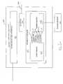
- FIG. 1is a schematic diagram of one embodiment of a splitter.
- FIG. 2is a block diagram of one embodiment of a network element of a communication network that is adapted to provide power to a subtended network element through using a splitter at the network element.
- FIG. 3is a block diagram of one embodiment of a communication system with a central office power plug that includes a splitter for combining power and communication signals for remotely powering a subtended network element.
- FIG. 1is a schematic diagram of one embodiment of a splitter indicated generally at 100 .
- Splitter 100is configured to inject power signals into a communication line that contemporaneously carries communication signals between network elements without impairing effectiveness of the communication signals.
- Splitter 100includes three interface ports: power port 102 , communication port 104 , and line port 106 .
- Power port 102is adapted to be coupled to a power supply for providing line power to a line-powered network element.
- power port 102is coupled to a DC power supply.
- the DC power supplyprovides a power signal for powering a remote communication device such as a remote terminal in a digital loop carrier, a digital subscriber line (DSL) modem, an integrated access device, or other appropriate network element.
- Communication port 104is adapted to be coupled to communication circuitry.
- communication port 104is coupled to circuitry that transmits and receives xDSL signals, e.g., ADSL, G.SHDSL, VDSL, or communication signals generated according to any other appropriate communication standard.
- Line port 106is adapted to couple to a communication line such as a twisted pair or other appropriate conductive medium.
- Power port 102is adapted to provide power signals for transmission on a communication line coupled to line port 106 .
- power port 102includes first and second terminals 108 and 110 .
- Terminals 108 and 110are adapted to be coupled to positive and negative terminals of a power supply circuit (not shown).
- the power signal at terminal 108is provided to line port 106 on tip (T) terminal 124 .
- the power signal at terminal 110is provided to line port 106 on ring (R) terminal 126 .
- the power signals provided to tip and ring terminals 124 and 126are filtered to provide separation from communication signals passing over the same communication lines.
- Splitter 100includes a number of components coupled between power supply port 102 and line port 106 that provide this filtering function. These components include capacitors 120 and coupled inductor 122 . The combination of the capacitors 120 and the inductors 122 provide low pass filtering for the power signals passing from terminal 108 to tip terminal 124 and from terminal 110 to ring terminal 126 .
- Capacitors 120 and coupled inductor 122provide a high AC impedance and low DC impedance for the power signal from power port 102 to line port 106 .
- Capacitors 120are coupled in parallel between nodes 116 and 118 .
- coupled inductor 122includes first and second windings 128 and 130 that are wrapped around a common core to provide first and second inductances.
- first and second windings 128 and 130that are wrapped around a common core to provide first and second inductances.
- Communication port 104is coupled to line port 106 through a circuit with low AC impedance and high DC impedance (high pass filter).
- Communication port 104includes tip (T) terminal 132 and ring (R) terminal 134 .
- tip terminal 132is coupled through capacitor 136 to tip terminal 124 of line port 106 .
- ring terminal 134is coupled through capacitor 138 to ring terminal 126 .
- Capacitors 136 and 138provide high DC impedance and low AC impedance.
- Splitter 100also includes a number of other components. Terminals 108 and 110 are also coupled to protection diodes 112 . Protection diodes 112 are configured to protect the power supply by restricting the direction of current flow in splitter 100 . Resistors 114 are also coupled between nodes 116 and 118 of splitter 100 . Resistors 114 provide a discharge path for the high voltage capacitors of the power supply when it is unplugged, preventing a shock hazard after the card is removed from service.
- Splitter 100also includes a number of overvoltage protection “crowbar” devices 140 - 1 to 140 - 4 to provide protection from voltage spikes such as spikes induced by lightning or the like.
- splitter 100injects power signals from power port 102 onto a communication line at line port 106 without substantial interference with the communication of communication signals between communication port 104 and line port 106 .
- Capacitors 136 and 138provide a high DC impedance and a low AC impedance so as to allow communication signals which may not be intended for line powered transport to be passed between communication port 104 and line port 106 .
- coupled inductor 122 and capacitors 120provide a low DC impedance and a high AC impedance to allow power signals to be injected from power supply port 102 onto communication lines at line port 106 without corrupting the communication signals.
- FIG. 2is a block diagram of one embodiment of a network element 200 that provides line powering for one or more other network elements over one or more communication lines, e.g., twisted-pair telephone lines.
- the embodiment of a source network element 200 shown in FIG. 2includes communication interface 202 and a power interface 204 .
- the communication interface 202includes appropriate components for providing the various telecommunications service provided by the source network element 200 .
- the communications interface 202couples the source network element 200 to at least one upstream G.SHDSL communication link and to at least one downstream G.SHDSL communication link via a splitter 230 .
- splitter 230is constructed as described above with respect to FIG. 1.
- the downstream G.SHDSL communication linkis provided over at least one twisted-pair telephone line 206 .
- communication signalsare generated according to any other appropriate communication standard.
- the twisted-pair telephone line 206is coupled, in one embodiment to one or more network elements (referred to generally as “sink network element” and not shown in FIG. 2) that are powered by the source network element 200 .
- the power interface 204includes a power supply 208 that is coupled to a power source 210 .
- the power supply 208receives power from the power source 210 and conditions and supplies power on the twisted-pair telephone lines 206 in order to power a sink network element coupled to the twisted-pair telephone line 206 .
- the power supply 208is implemented as a fly-back power supply.
- the source network element 200includes a splitter 230 that combines an output communication signal from the communications interface 202 and an output power signal from the power interface 204 and applies the combined output signal to the twisted-pair telephone line 206 .
- the splitter 230also receives an input signal from the twisted-pair telephone line 206 and splits off that portion of the received input signal used for providing the downstream communication link and provides it to the communications interface 202 for appropriate processing.
- One embodiment of a splitter 230is described above with respect to FIG. 1.
- the power interface 204also includes a controller 212 that controls the operation of the power supply 208 .
- controller 212is implemented in hardware (for example, using analog and/or digital circuits) and/or in software (for example, by programming a programmable processor with appropriate instructions to carry out the various control functions described here).
- the controller 212is implemented in other ways.
- the controller 212is shown as being a part of the power interface 204 in FIG. 2, in other embodiments the controller 212 is a part of a general controller or control circuitry for the central office terminal 200 . In other embodiments, the functions performed by the controller 212 are incorporated directly into control circuitry of the power supply 208 .
- a voltage signal 214is provided between the controller 212 and the power supply 208 .
- the voltage signal 214is used by the controller 212 to set a nominal voltage at which the power supply 208 is to supply power on the twisted-pair telephone line 206 in order to power a sink network element coupled to the twisted-pair telephone line 206 .
- a power limit signal 216is provided between the controller 212 and the power supply 208 .
- the power limit signal 216is used by the controller 212 to set a power limit for the power supply 208 .
- the power limitis a maximum power the power supply 208 is to provide on the twisted-pair telephone line 206 .
- An overload signal 218is provided by the power supply 208 to the controller 212 .
- the overload signal 218is used by the power supply 208 to inform the controller 212 that the power supply 208 is currently supplying power with an output voltage that is below the nominal voltage specified on the voltage signal 214 .
- Thisis referred to here as an “overload condition” or that the power supply 208 is “out of regulation.”
- the power supply 208drops the output voltage so that the total power supplied by the power supply 208 does not exceed the power limit.
- the power supply 208indicates that such an overload condition exists on the overload signal 218 .
- various current measurement signalsare supplied by the power supply 208 to the controller 212 .
- a low current signal 220is supplied by the power supply 208 to the controller 212 to indicate that the current currently supplied by the power supply 208 is below some relatively low threshold current value.
- a high current signal 222is supplied by the power supply 208 to controller 212 to indicate that the current currently supplied by the power supply 208 is above some relatively high current value.
- the amount of current currently supplied by the power supply 208is measured and provided to the controller 212 .
- FIG. 3is a block diagram of one embodiment of a wireless network 300 .
- the embodiment of a wireless network 300 shown in FIG. 3includes a central office power plug 302 that is coupled to a power source 304 .
- central office power plug 302is implemented using an embodiment of the source network element 200 described above.
- An upstream G.SHDSL communication link 306is provided to the central office power plug 302 over an upstream communication medium (for example, a twisted-pair telephone line).
- the upstream G.SHDSL communication link 306couples the central office power plug 302 to a G.SHDSL line interface unit 308 .
- the G.SHDSL line interface unit 308is coupled to an upstream network (not shown) such as the Internet.
- the G.SHDSL line interface units 308is inserted into a subscriber access multiplexer (not shown) in order to couple the G.SHDSL line interface unit 308 to the upstream network.
- the wireless network 300also includes a remote network element 310 .
- Remote network element 310is powered by a twisted-pair telephone line 312 that is coupled between the central office power plug 302 and the remote network element 310 .
- a downstream G.SHDSL communication link 314is provided over the twisted-pair telephone line 312 .
- the central office power plug 302supplies power for the remote network element 310 on the twisted-pair telephone line 312 in the same manner as described above in connection with FIG. 2.
- the remote network element 310includes a power supply 318 that is coupled to the twisted-pair telephone line 312 .
- the power supply 318extracts the power supplied on the twisted-pair telephone line 312 by the central office power plug 302 .
- the extracted poweris used to power various components of the remote network element 310 .
- the remote network element 310also includes a G.SHDSL modem 320 that modulates and demodulates the G.SHDSL signals carried over the twisted-pair telephone line 312 .
- the modem 320is coupled to a wireless access point 322 over an Ethernet connection 324 .
- the wireless access point 322transmits traffic to, and receives traffic from various wireless devices (not shown) over a wireless link 326 . Examples of wireless devices include computers or personal digital assistants having wireless transceivers.
- the wireless access point 322is a wireless access point that supports the Institute for Electrical and Electronic Engineers (IEEE) 802.11b standard (also referred to as “WI-FI”), 802.11a, HomeRF, or any other appropriate wireless communication standard.
- IEEEInstitute for Electrical and Electronic Engineers
- WI-FIInstitute for Electrical and Electronic Engineers
- the wireless access point 322is replaced with circuitry for a wired local area network connection.
- the wireless network 300also includes a wireless services manager 328 that manages the wireless services provided over the wireless network 300 .
- wireless services manager 328manages authentication and other subscriber and service-related information using the Remote Authentication Dial-in User Service (RADIUS) protocol.
- the wireless services manager 328is coupled to the G.SHDSL line interface unit 308 using a local area network connection (for example, an Ethernet connection).
- wireless trafficis received by the wireless access point 322 from various wireless devices.
- the wireless trafficis transmitted to the central office power plug 302 by the G.SHDSL modem 320 over the twisted-pair telephone line 312 .
- a splitter(not shown in FIG. 3) splits off that portion of the signal used for providing the G.SHDSL communication link and provides it to a communications interface (not shown in FIG. 3) of the central office power plug 302 for appropriate processing.
- the communications interfacetransmits the traffic to the G.SHDSL line interface unit 308 over the upstream G.SHDSL communication link 306 , where the traffic is processed and forwarded to the upstream network by the line interface unit 308 .
- trafficis received by the G.SHDSL line interface unit 308 from the upstream network.
- the trafficis transmitted to the central office power plug 302 over the upstream communication link 306 .
- the trafficis combined with power from a power supply (not shown in FIG. 3) of the central office power plug 302 by the splitter and the combined signal is transmitted on the twisted-pair telephone line 312 .
- the signalis received by the G.SHDSL modem 320 , which forwards the traffic to the wireless access point 322 for transmission to the wireless devices.
Landscapes
- Cable Transmission Systems, Equalization Of Radio And Reduction Of Echo (AREA)
- Telephonic Communication Services (AREA)
Abstract
Description
- Telecommunications networks transport signals between user equipment at diverse locations. A telecommunications network includes a number of components. For example, a telecommunications network typically includes a number of switching elements that provide selective routing of signals between network elements. Additionally, telecommunications networks include communication media, e.g., twisted pair, fiber optic cable, coaxial cable or the like that transport the signals between switches. Further, some telecommunications networks include access networks.[0001]
- For purposes of this specification, the term “access network” means a portion of a telecommunication network, e.g., the public switched telephone network (PSTN), that allows subscriber equipment or devices to connect to a core network. For purposes of this specification, the term access network further includes customer located equipment (CLE) even if commonly considered part of an enterprise network. Examples of conventional access networks include a cable plant and equipment normally located in a central office or outside plant cabinets that directly provides service interface to subscribers in a service area. The access network provides the interface between the subscriber service end points and the communication network that provides the given service. An access network typically includes a number of network elements.[0002]
- A network element is a facility or the equipment in the access-network that provides the service interfaces for the provisioned telecommunication services. A network element may be a stand-alone device or may be distributed among a number of devices. A network element is either central office located, outside plant located, or customer located equipment (CLE). Some network elements are hardened for outside plant environments. In some access networks as defined herein, various network elements may be owned by different entities. For example, the majority of the network elements in an access network may be owned by one of the Regional Bell Operating Companies (RBOCs) whereas the CLE may be owned by the subscriber. Such subscriber equipment is conventionally considered part of the subscriber's enterprise network, but, for purposes of this specification may be defined to part of the access network.[0003]
- There are a number of conventional forms for access networks. For example, the digital loop carrier is an early form of access network. The conventional digital loop carrier transported signals to and from subscriber equipment using two network elements. At the core network side, a central office terminal is provided. The central office terminal is connected to the remote terminal over a high-speed digital link, e.g., a number of T[0004]1 lines or other appropriate high-speed digital transport medium. The remote terminal of the digital loop carrier typically connects to the subscriber over a conventional twisted pair drop.
- The remote terminal of a digital loop carrier is often deployed deep in the customer service area. The remote terminal typically has line cards and other electronic circuits that need power to operate properly. In some applications, the remote terminal is powered locally. Unfortunately, to prevent failure of the remote terminal due to loss of local power, a local battery plant is typically used. This adds to the cost and complicates the maintainability of the remote terminal, due to the outside plant operational requirements which stipulate operation over extended temperature ranges.[0005]
- In some networks, the remote terminal is fed power over a line from the central office. This is referred to as line feeding or line powering and can be accomplished through use of an AC or a DC source. Thus, if local power fails, the remote terminal still functions because it is typically powered over the line using a battery-backed power source. This allows the remote terminal to offer critical functions like lifeline plain old-fashioned telephone service (POTS) even during a power outage.[0006]
- In a typical system offering line powering, the circuit that injects the power also is the source of the communication signals provided to the communication lines. The design of the power injection circuitry becomes complicated when the power signal is inserted in a different circuit from the circuit that terminates the communication signals. Therefore, there is a need in the art for improvements in the manner in which power is provided to network elements in an access network to allow injection of power signals onto a line carrying communication signals.[0007]
- Embodiments of the present invention address problems with providing power to network elements in an access network. Particularly, in one embodiment, a splitter for enabling a power signal and a communication signal to be transmitted over a common communication link is provided. The splitter includes a line port adapted to be coupled to a communication line, a power port adapted to be coupled to a power supply to receive a power signal, and a communication port adapted to be coupled to a communication circuit that generates and receives communication signals. The splitter also includes a low pass filter coupled between the power port and the line port, the low pass filter including a coupled inductor, a high pass filter coupled to the communication port, and wherein the communication signals and the power signal are transported on the communication line at the line port.[0008]
- FIG. 1 is a schematic diagram of one embodiment of a splitter.[0009]
- FIG. 2 is a block diagram of one embodiment of a network element of a communication network that is adapted to provide power to a subtended network element through using a splitter at the network element.[0010]
- FIG. 3 is a block diagram of one embodiment of a communication system with a central office power plug that includes a splitter for combining power and communication signals for remotely powering a subtended network element.[0011]
- In the following detailed description, reference is made to the accompanying drawings that form a part hereof, and in which is shown by way of illustration specific illustrative embodiments in which the invention may be practiced. These embodiments are described in sufficient detail to enable those skilled in the art to practice the invention, and it is to be understood that other embodiments may be utilized and that logical, mechanical and electrical changes may be made without departing from the spirit and scope of the present invention. The following detailed description is, therefore, not to be taken in a limiting sense.[0012]
- FIG. 1 is a schematic diagram of one embodiment of a splitter indicated generally at[0013]100. Splitter100 is configured to inject power signals into a communication line that contemporaneously carries communication signals between network elements without impairing effectiveness of the communication signals.
- Splitter[0014]100 includes three interface ports:
power port 102,communication port 104, andline port 106.Power port 102 is adapted to be coupled to a power supply for providing line power to a line-powered network element. In one embodiment,power port 102 is coupled to a DC power supply. The DC power supply provides a power signal for powering a remote communication device such as a remote terminal in a digital loop carrier, a digital subscriber line (DSL) modem, an integrated access device, or other appropriate network element.Communication port 104 is adapted to be coupled to communication circuitry. For example, in one embodiment,communication port 104 is coupled to circuitry that transmits and receives xDSL signals, e.g., ADSL, G.SHDSL, VDSL, or communication signals generated according to any other appropriate communication standard.Line port 106 is adapted to couple to a communication line such as a twisted pair or other appropriate conductive medium. - [0015]
Power port 102 is adapted to provide power signals for transmission on a communication line coupled toline port 106. In one embodiment,power port 102 includes first andsecond terminals Terminals terminal 108 is provided toline port 106 on tip (T)terminal 124. Similarly, the power signal atterminal 110 is provided toline port 106 on ring (R)terminal 126. The power signals provided to tip andring terminals - Splitter[0016]100 includes a number of components coupled between
power supply port 102 andline port 106 that provide this filtering function. These components includecapacitors 120 and coupledinductor 122. The combination of thecapacitors 120 and theinductors 122 provide low pass filtering for the power signals passing fromterminal 108 to tip terminal124 and from terminal110 to ring terminal126. - [0017]
Capacitors 120 and coupledinductor 122 provide a high AC impedance and low DC impedance for the power signal frompower port 102 toline port 106.Capacitors 120 are coupled in parallel betweennodes inductor 122 includes first andsecond windings - [0018]
Communication port 104 is coupled toline port 106 through a circuit with low AC impedance and high DC impedance (high pass filter).Communication port 104 includes tip (T)terminal 132 and ring (R)terminal 134. In one embodiment,tip terminal 132 is coupled throughcapacitor 136 to tip terminal124 ofline port 106. Similarly,ring terminal 134 is coupled through capacitor138 to ring terminal126.Capacitors 136 and138 provide high DC impedance and low AC impedance. - [0019]
Splitter 100 also includes a number of other components.Terminals protection diodes 112.Protection diodes 112 are configured to protect the power supply by restricting the direction of current flow insplitter 100. Resistors114 are also coupled betweennodes splitter 100. Resistors114 provide a discharge path for the high voltage capacitors of the power supply when it is unplugged, preventing a shock hazard after the card is removed from service.Splitter 100 also includes a number of overvoltage protection “crowbar” devices140-1 to140-4 to provide protection from voltage spikes such as spikes induced by lightning or the like. - In operation,[0020]
splitter 100 injects power signals frompower port 102 onto a communication line atline port 106 without substantial interference with the communication of communication signals betweencommunication port 104 andline port 106.Capacitors 136 and138 provide a high DC impedance and a low AC impedance so as to allow communication signals which may not be intended for line powered transport to be passed betweencommunication port 104 andline port 106. Further, coupledinductor 122 andcapacitors 120 provide a low DC impedance and a high AC impedance to allow power signals to be injected frompower supply port 102 onto communication lines atline port 106 without corrupting the communication signals. - FIG. 2 is a block diagram of one embodiment of a[0021]
network element 200 that provides line powering for one or more other network elements over one or more communication lines, e.g., twisted-pair telephone lines. The embodiment of asource network element 200 shown in FIG. 2 includescommunication interface 202 and apower interface 204. Thecommunication interface 202 includes appropriate components for providing the various telecommunications service provided by thesource network element 200. For example, in the embodiment shown in FIG. 2, the communications interface202 couples thesource network element 200 to at least one upstream G.SHDSL communication link and to at least one downstream G.SHDSL communication link via asplitter 230. In one embodiment,splitter 230 is constructed as described above with respect to FIG. 1. The downstream G.SHDSL communication link is provided over at least one twisted-pair telephone line 206. In other embodiments, communication signals are generated according to any other appropriate communication standard. The twisted-pair telephone line 206 is coupled, in one embodiment to one or more network elements (referred to generally as “sink network element” and not shown in FIG. 2) that are powered by thesource network element 200. - The[0022]
power interface 204 includes apower supply 208 that is coupled to apower source 210. In general, thepower supply 208 receives power from thepower source 210 and conditions and supplies power on the twisted-pair telephone lines 206 in order to power a sink network element coupled to the twisted-pair telephone line 206. In one such embodiment, thepower supply 208 is implemented as a fly-back power supply. Thesource network element 200 includes asplitter 230 that combines an output communication signal from thecommunications interface 202 and an output power signal from thepower interface 204 and applies the combined output signal to the twisted-pair telephone line 206. Thesplitter 230 also receives an input signal from the twisted-pair telephone line 206 and splits off that portion of the received input signal used for providing the downstream communication link and provides it to thecommunications interface 202 for appropriate processing. One embodiment of asplitter 230 is described above with respect to FIG. 1. - The[0023]
power interface 204 also includes acontroller 212 that controls the operation of thepower supply 208. In one such embodiment,controller 212 is implemented in hardware (for example, using analog and/or digital circuits) and/or in software (for example, by programming a programmable processor with appropriate instructions to carry out the various control functions described here). In other embodiments, thecontroller 212 is implemented in other ways. Although thecontroller 212 is shown as being a part of thepower interface 204 in FIG. 2, in other embodiments thecontroller 212 is a part of a general controller or control circuitry for thecentral office terminal 200. In other embodiments, the functions performed by thecontroller 212 are incorporated directly into control circuitry of thepower supply 208. - In the embodiment shown in FIG. 2, a[0024]
voltage signal 214 is provided between thecontroller 212 and thepower supply 208. Thevoltage signal 214 is used by thecontroller 212 to set a nominal voltage at which thepower supply 208 is to supply power on the twisted-pair telephone line 206 in order to power a sink network element coupled to the twisted-pair telephone line 206. Apower limit signal 216 is provided between thecontroller 212 and thepower supply 208. Thepower limit signal 216 is used by thecontroller 212 to set a power limit for thepower supply 208. The power limit is a maximum power thepower supply 208 is to provide on the twisted-pair telephone line 206. - An[0025]
overload signal 218 is provided by thepower supply 208 to thecontroller 212. Theoverload signal 218 is used by thepower supply 208 to inform thecontroller 212 that thepower supply 208 is currently supplying power with an output voltage that is below the nominal voltage specified on thevoltage signal 214. This is referred to here as an “overload condition” or that thepower supply 208 is “out of regulation.” For example, when a sink network element coupled to the twisted-pair telephone line 206 draws an amount of current that causes the amount of power supplied by thepower supply 208 to exceed the power limit specified by thepower limit signal 216, thepower supply 208 drops the output voltage so that the total power supplied by thepower supply 208 does not exceed the power limit. When an overload condition exists, thepower supply 208 indicates that such an overload condition exists on theoverload signal 218. - In the embodiment shown in FIG. 2, various current measurement signals are supplied by the[0026]
power supply 208 to thecontroller 212. For example, a lowcurrent signal 220 is supplied by thepower supply 208 to thecontroller 212 to indicate that the current currently supplied by thepower supply 208 is below some relatively low threshold current value. A highcurrent signal 222 is supplied by thepower supply 208 tocontroller 212 to indicate that the current currently supplied by thepower supply 208 is above some relatively high current value. In other embodiments, the amount of current currently supplied by thepower supply 208 is measured and provided to thecontroller 212. - FIG. 3 is a block diagram of one embodiment of a wireless network[0027]300. The embodiment of a wireless network300 shown in FIG. 3 includes a central
office power plug 302 that is coupled to a power source304. In one embodiment, centraloffice power plug 302 is implemented using an embodiment of thesource network element 200 described above. An upstream G.SHDSL communication link306 is provided to the centraloffice power plug 302 over an upstream communication medium (for example, a twisted-pair telephone line). The upstream G.SHDSL communication link306 couples the centraloffice power plug 302 to a G.SHDSLline interface unit 308. The G.SHDSLline interface unit 308 is coupled to an upstream network (not shown) such as the Internet. In one such embodiment, the G.SHDSLline interface units 308 is inserted into a subscriber access multiplexer (not shown) in order to couple the G.SHDSLline interface unit 308 to the upstream network. - The wireless network[0028]300 also includes a
remote network element 310.Remote network element 310 is powered by a twisted-pair telephone line 312 that is coupled between the centraloffice power plug 302 and theremote network element 310. A downstream G.SHDSL communication link 314 is provided over the twisted-pair telephone line 312. The centraloffice power plug 302 supplies power for theremote network element 310 on the twisted-pair telephone line 312 in the same manner as described above in connection with FIG. 2. Theremote network element 310 includes apower supply 318 that is coupled to the twisted-pair telephone line 312. Thepower supply 318 extracts the power supplied on the twisted-pair telephone line 312 by the centraloffice power plug 302. The extracted power is used to power various components of theremote network element 310. - The[0029]
remote network element 310 also includes aG.SHDSL modem 320 that modulates and demodulates the G.SHDSL signals carried over the twisted-pair telephone line 312. Themodem 320 is coupled to awireless access point 322 over anEthernet connection 324. Thewireless access point 322 transmits traffic to, and receives traffic from various wireless devices (not shown) over awireless link 326. Examples of wireless devices include computers or personal digital assistants having wireless transceivers. In one embodiment, thewireless access point 322 is a wireless access point that supports the Institute for Electrical and Electronic Engineers (IEEE) 802.11b standard (also referred to as “WI-FI”), 802.11a, HomeRF, or any other appropriate wireless communication standard. In other embodiments, thewireless access point 322 is replaced with circuitry for a wired local area network connection. - The wireless network[0030]300 also includes a
wireless services manager 328 that manages the wireless services provided over the wireless network300. For example, in one embodiment,wireless services manager 328 manages authentication and other subscriber and service-related information using the Remote Authentication Dial-in User Service (RADIUS) protocol. In one embodiment, thewireless services manager 328 is coupled to the G.SHDSLline interface unit 308 using a local area network connection (for example, an Ethernet connection). - In operation, wireless traffic is received by the[0031]
wireless access point 322 from various wireless devices. The wireless traffic is transmitted to the centraloffice power plug 302 by theG.SHDSL modem 320 over the twisted-pair telephone line 312. A splitter (not shown in FIG. 3) splits off that portion of the signal used for providing the G.SHDSL communication link and provides it to a communications interface (not shown in FIG. 3) of the centraloffice power plug 302 for appropriate processing. The communications interface transmits the traffic to the G.SHDSLline interface unit 308 over the upstream G.SHDSL communication link306, where the traffic is processed and forwarded to the upstream network by theline interface unit 308. In the downstream direction, traffic is received by the G.SHDSLline interface unit 308 from the upstream network. The traffic is transmitted to the centraloffice power plug 302 over the upstream communication link306. The traffic is combined with power from a power supply (not shown in FIG. 3) of the centraloffice power plug 302 by the splitter and the combined signal is transmitted on the twisted-pair telephone line 312. The signal is received by theG.SHDSL modem 320, which forwards the traffic to thewireless access point 322 for transmission to the wireless devices.
Claims (20)
Priority Applications (8)
| Application Number | Priority Date | Filing Date | Title |
|---|---|---|---|
| US10/449,546US6998964B2 (en) | 2003-05-30 | 2003-05-30 | Splitter |
| JP2006514962AJP2006526955A (en) | 2003-05-30 | 2004-05-26 | Splitter |
| AU2004246154AAU2004246154B2 (en) | 2003-05-30 | 2004-05-26 | Splitter |
| EP04753349AEP1629595A4 (en) | 2003-05-30 | 2004-05-26 | Splitter |
| BRPI0410825-6ABRPI0410825A (en) | 2003-05-30 | 2004-05-26 | splitter, circuit, and method for injecting power over a line, source network element, and wireless system |
| CN2004800224774ACN1833360B (en) | 2003-05-30 | 2004-05-26 | Circuit and method for injecting power signal onto communication line |
| CA002527678ACA2527678A1 (en) | 2003-05-30 | 2004-05-26 | Splitter |
| PCT/US2004/016506WO2004109934A2 (en) | 2003-05-30 | 2004-05-26 | Splitter |
Applications Claiming Priority (1)
| Application Number | Priority Date | Filing Date | Title |
|---|---|---|---|
| US10/449,546US6998964B2 (en) | 2003-05-30 | 2003-05-30 | Splitter |
Publications (2)
| Publication Number | Publication Date |
|---|---|
| US20040239448A1true US20040239448A1 (en) | 2004-12-02 |
| US6998964B2 US6998964B2 (en) | 2006-02-14 |
Family
ID=33451810
Family Applications (1)
| Application Number | Title | Priority Date | Filing Date |
|---|---|---|---|
| US10/449,546Expired - LifetimeUS6998964B2 (en) | 2003-05-30 | 2003-05-30 | Splitter |
Country Status (8)
| Country | Link |
|---|---|
| US (1) | US6998964B2 (en) |
| EP (1) | EP1629595A4 (en) |
| JP (1) | JP2006526955A (en) |
| CN (1) | CN1833360B (en) |
| AU (1) | AU2004246154B2 (en) |
| BR (1) | BRPI0410825A (en) |
| CA (1) | CA2527678A1 (en) |
| WO (1) | WO2004109934A2 (en) |
Cited By (1)
| Publication number | Priority date | Publication date | Assignee | Title |
|---|---|---|---|---|
| WO2004110077A2 (en) | 2003-05-30 | 2004-12-16 | Adc Dsl Systems, Inc. | Input voltage sense circuit in a line powered network element |
Families Citing this family (29)
| Publication number | Priority date | Publication date | Assignee | Title |
|---|---|---|---|---|
| US6480510B1 (en)* | 1998-07-28 | 2002-11-12 | Serconet Ltd. | Local area network of serial intelligent cells |
| US6956826B1 (en) | 1999-07-07 | 2005-10-18 | Serconet Ltd. | Local area network for distributing data communication, sensing and control signals |
| US6690677B1 (en) | 1999-07-20 | 2004-02-10 | Serconet Ltd. | Network for telephony and data communication |
| US6549616B1 (en) | 2000-03-20 | 2003-04-15 | Serconet Ltd. | Telephone outlet for implementing a local area network over telephone lines and a local area network using such outlets |
| IL135744A (en)* | 2000-04-18 | 2008-08-07 | Mosaid Technologies Inc | Telephone communication system over a single telephone line |
| US6842459B1 (en)* | 2000-04-19 | 2005-01-11 | Serconet Ltd. | Network combining wired and non-wired segments |
| IL144158A (en)* | 2001-07-05 | 2011-06-30 | Mosaid Technologies Inc | Outlet for connecting an analog telephone set to a digital data network carrying voice signals in digital form |
| EP2234394A1 (en)* | 2001-10-11 | 2010-09-29 | Mosaid Technologies Incorporated | Coupling device |
| IL154234A (en) | 2003-01-30 | 2010-12-30 | Mosaid Technologies Inc | Method and system for providing dc power on local telephone lines |
| IL154921A (en)* | 2003-03-13 | 2011-02-28 | Mosaid Technologies Inc | Telephone system having multiple distinct sources and accessories therefor |
| IL157787A (en) | 2003-09-07 | 2010-12-30 | Mosaid Technologies Inc | Modular outlet for data communications network |
| IL159838A0 (en) | 2004-01-13 | 2004-06-20 | Yehuda Binder | Information device |
| US7280808B2 (en)* | 2004-04-12 | 2007-10-09 | Sony Ericsson Mobile Communications, Ab | Wireless communications devices including circuit substrates with partially overlapping conductors thereon coupling power to/from power amplifier systems |
| IL161869A (en) | 2004-05-06 | 2014-05-28 | Serconet Ltd | System and method for carrying a wireless based signal over wiring |
| US7839662B2 (en)* | 2004-09-20 | 2010-11-23 | Adc Dsl Systems, Inc. | Power supply having a flyback topology and current sense transformer |
| US7873058B2 (en) | 2004-11-08 | 2011-01-18 | Mosaid Technologies Incorporated | Outlet with analog signal adapter, a method for use thereof and a network using said outlet |
| US7872881B2 (en)* | 2005-08-17 | 2011-01-18 | Adc Dsl Systems, Inc. | Secondary regulation in a multiple output flyback topology |
| US7813451B2 (en) | 2006-01-11 | 2010-10-12 | Mobileaccess Networks Ltd. | Apparatus and method for frequency shifting of a wireless signal and systems using frequency shifting |
| US8154153B2 (en)* | 2007-01-25 | 2012-04-10 | Systems General Corp. | Method and apparatus for providing a communication channel through an output cable of a power supply |
| US8005206B1 (en) | 2007-03-15 | 2011-08-23 | Bh Electronics, Inc. | VDSL splitter |
| US8594133B2 (en) | 2007-10-22 | 2013-11-26 | Corning Mobileaccess Ltd. | Communication system using low bandwidth wires |
| US8175649B2 (en) | 2008-06-20 | 2012-05-08 | Corning Mobileaccess Ltd | Method and system for real time control of an active antenna over a distributed antenna system |
| WO2009149533A1 (en)* | 2008-06-09 | 2009-12-17 | Genesis Technical Systems, Corp. | Bonded interconnection of local networks |
| WO2010089719A1 (en) | 2009-02-08 | 2010-08-12 | Mobileaccess Networks Ltd. | Communication system using cables carrying ethernet signals |
| US20110077878A1 (en)* | 2009-09-30 | 2011-03-31 | Lathrop Frederick L | Power supply with data communications |
| WO2012044275A1 (en) | 2010-09-27 | 2012-04-05 | Hewlett-Packard Development Company L.P. | Computer system with power measurement |
| EP2829152A2 (en) | 2012-03-23 | 2015-01-28 | Corning Optical Communications Wireless Ltd. | Radio-frequency integrated circuit (rfic) chip(s) for providing distributed antenna system functionalities, and related components, systems, and methods |
| US9979505B2 (en) | 2012-09-10 | 2018-05-22 | Tellabs Enterprise, Inc. | Delivery of GPON technology |
| US9184960B1 (en) | 2014-09-25 | 2015-11-10 | Corning Optical Communications Wireless Ltd | Frequency shifting a communications signal(s) in a multi-frequency distributed antenna system (DAS) to avoid or reduce frequency interference |
Citations (12)
| Publication number | Priority date | Publication date | Assignee | Title |
|---|---|---|---|---|
| US3717858A (en)* | 1970-08-12 | 1973-02-20 | D Hadden | Two conductor telemetering system |
| US3870822A (en)* | 1971-02-16 | 1975-03-11 | Post Office | Supplying a charging current by way of telephone lines or the like |
| US3968333A (en)* | 1973-09-18 | 1976-07-06 | Superior Continental Corporation | Battery charger control circuit for telephone transmission systems |
| US4639714A (en)* | 1984-12-21 | 1987-01-27 | Ferranti Subsea Systems, Ltd. | Combined power and control signal transmission system |
| US5148144A (en)* | 1991-03-28 | 1992-09-15 | Echelon Systems Corporation | Data communication network providing power and message information |
| US5777769A (en)* | 1995-12-28 | 1998-07-07 | Lucent Technologies Inc. | Device and method for providing high speed data transfer through a drop line of a power line carrier communication system |
| US5793265A (en)* | 1997-05-30 | 1998-08-11 | Microphase Corporation | Compact diplexer |
| US5818127A (en)* | 1989-04-28 | 1998-10-06 | Videocom, Inc. | Transmission of FM video signals over various lines |
| US5977650A (en)* | 1998-03-17 | 1999-11-02 | Northern Telecom Limited | Transmitting communications signals over a power line network |
| US6037678A (en)* | 1997-10-03 | 2000-03-14 | Northern Telecom Limited | Coupling communications signals to a power line |
| US6329906B1 (en)* | 1997-05-29 | 2001-12-11 | 3Com Corporation | Power transfer apparatus for concurrently transmitting data and power over data wires |
| US6580254B2 (en)* | 2001-03-09 | 2003-06-17 | Adtran, Inc. | Apparatus and method for providing span power to communication equipment at a customer premise |
Family Cites Families (8)
| Publication number | Priority date | Publication date | Assignee | Title |
|---|---|---|---|---|
| CA899475A (en)* | 1970-10-20 | 1972-05-02 | Lindsay Specialty Products Limited | Signal routing device |
| US4394631A (en)* | 1981-05-29 | 1983-07-19 | C-Cor Electronics, Inc. | Radio frequency choke and method of use |
| JPS61174713U (en)* | 1985-04-22 | 1986-10-30 | ||
| JPH08280068A (en)* | 1995-04-06 | 1996-10-22 | Daikin Ind Ltd | Power supply adapter for transmission device and transmission device |
| US5959507A (en)* | 1998-01-12 | 1999-09-28 | General Instrument Corporation | CATV passive component with RF splitter and power adding/removal port |
| JP3328227B2 (en)* | 1999-06-22 | 2002-09-24 | 株式会社エヌ・ティ・ティ・データ | Data communication system |
| US6624745B1 (en)* | 2000-05-18 | 2003-09-23 | Advanced Micro Devices, Inc. | Low pass filter for a universal home network on a customer premises european installation bus |
| US7003102B2 (en)* | 2001-10-10 | 2006-02-21 | Pulse Engineering, Inc. | Telecommunications gateway and method |
- 2003
- 2003-05-30USUS10/449,546patent/US6998964B2/ennot_activeExpired - Lifetime
- 2004
- 2004-05-26EPEP04753349Apatent/EP1629595A4/ennot_activeWithdrawn
- 2004-05-26CACA002527678Apatent/CA2527678A1/ennot_activeAbandoned
- 2004-05-26JPJP2006514962Apatent/JP2006526955A/enactivePending
- 2004-05-26AUAU2004246154Apatent/AU2004246154B2/ennot_activeCeased
- 2004-05-26WOPCT/US2004/016506patent/WO2004109934A2/enactiveApplication Filing
- 2004-05-26CNCN2004800224774Apatent/CN1833360B/ennot_activeExpired - Fee Related
- 2004-05-26BRBRPI0410825-6Apatent/BRPI0410825A/ennot_activeIP Right Cessation
Patent Citations (12)
| Publication number | Priority date | Publication date | Assignee | Title |
|---|---|---|---|---|
| US3717858A (en)* | 1970-08-12 | 1973-02-20 | D Hadden | Two conductor telemetering system |
| US3870822A (en)* | 1971-02-16 | 1975-03-11 | Post Office | Supplying a charging current by way of telephone lines or the like |
| US3968333A (en)* | 1973-09-18 | 1976-07-06 | Superior Continental Corporation | Battery charger control circuit for telephone transmission systems |
| US4639714A (en)* | 1984-12-21 | 1987-01-27 | Ferranti Subsea Systems, Ltd. | Combined power and control signal transmission system |
| US5818127A (en)* | 1989-04-28 | 1998-10-06 | Videocom, Inc. | Transmission of FM video signals over various lines |
| US5148144A (en)* | 1991-03-28 | 1992-09-15 | Echelon Systems Corporation | Data communication network providing power and message information |
| US5777769A (en)* | 1995-12-28 | 1998-07-07 | Lucent Technologies Inc. | Device and method for providing high speed data transfer through a drop line of a power line carrier communication system |
| US6329906B1 (en)* | 1997-05-29 | 2001-12-11 | 3Com Corporation | Power transfer apparatus for concurrently transmitting data and power over data wires |
| US5793265A (en)* | 1997-05-30 | 1998-08-11 | Microphase Corporation | Compact diplexer |
| US6037678A (en)* | 1997-10-03 | 2000-03-14 | Northern Telecom Limited | Coupling communications signals to a power line |
| US5977650A (en)* | 1998-03-17 | 1999-11-02 | Northern Telecom Limited | Transmitting communications signals over a power line network |
| US6580254B2 (en)* | 2001-03-09 | 2003-06-17 | Adtran, Inc. | Apparatus and method for providing span power to communication equipment at a customer premise |
Cited By (1)
| Publication number | Priority date | Publication date | Assignee | Title |
|---|---|---|---|---|
| WO2004110077A2 (en) | 2003-05-30 | 2004-12-16 | Adc Dsl Systems, Inc. | Input voltage sense circuit in a line powered network element |
Also Published As
| Publication number | Publication date |
|---|---|
| CA2527678A1 (en) | 2004-12-16 |
| WO2004109934A3 (en) | 2005-10-06 |
| CN1833360B (en) | 2011-11-16 |
| CN1833360A (en) | 2006-09-13 |
| JP2006526955A (en) | 2006-11-24 |
| AU2004246154B2 (en) | 2009-08-06 |
| WO2004109934A2 (en) | 2004-12-16 |
| EP1629595A2 (en) | 2006-03-01 |
| US6998964B2 (en) | 2006-02-14 |
| AU2004246154A1 (en) | 2004-12-16 |
| EP1629595A4 (en) | 2006-10-04 |
| BRPI0410825A (en) | 2006-06-27 |
Similar Documents
| Publication | Publication Date | Title |
|---|---|---|
| US6998964B2 (en) | Splitter | |
| EP2601746B1 (en) | Method and device for coupling a dc supply line to a telephone line or coaxial cable | |
| JP2850126B2 (en) | Line interface circuit | |
| US6917681B2 (en) | Peak power management and active decoupling arrangement for span-powered remote terminal access platforms | |
| CA3029294C (en) | Reverse power feeding power sourcing equipment and method | |
| CA2527283C (en) | Power ramp-up in a line-powered network element system | |
| US6967585B2 (en) | Input voltage sense circuit in a line powered network element | |
| US9374452B2 (en) | Apparatus and method for detection of off-hook phone in reverse power feeding architecture | |
| US7113591B2 (en) | Current sense circuit in a line powered network element | |
| US7457405B2 (en) | Enhanced low pass filter | |
| US20040239512A1 (en) | Lightning protection for a network element | |
| EP1465314B1 (en) | AC coupling-DC blocking surge protection module with DC blocking bypass functionality | |
| US7821758B1 (en) | Systems and methods for reducing intermodulation distortion |
Legal Events
| Date | Code | Title | Description |
|---|---|---|---|
| AS | Assignment | Owner name:ADC DSL SYSTEMS, INC., MINNESOTA Free format text:ASSIGNMENT OF ASSIGNORS INTEREST;ASSIGNORS:LOMAX, CHARLES WESTON JR.;TOLLERSON, CLARK WAYNE;POWERS, RANDALL L.;REEL/FRAME:014492/0683 Effective date:20030908 | |
| STCF | Information on status: patent grant | Free format text:PATENTED CASE | |
| FPAY | Fee payment | Year of fee payment:4 | |
| FPAY | Fee payment | Year of fee payment:8 | |
| AS | Assignment | Owner name:WILMINGTON TRUST, NATIONAL ASSOCIATION, AS THE COL Free format text:PATENT SECURITY AGREEMENT;ASSIGNOR:ADC DSL SYSTEMS, INC.;REEL/FRAME:036718/0042 Effective date:20150928 Owner name:JPMORGAN CHASE BANK, N.A., AS COLLATERAL AGENT, IL Free format text:PATENT SECURITY AGREEMENT - TERM LOAN;ASSIGNOR:ADC DSL SYSTEMS, INC.;REEL/FRAME:036714/0808 Effective date:20150928 Owner name:JPMORGAN CHASE BANK, N.A., AS COLLATERAL AGENT, IL Free format text:PATENT SECURITY AGREEMENT - ABL;ASSIGNOR:ADC DSL SYSTEMS, INC.;REEL/FRAME:036715/0164 Effective date:20150928 | |
| AS | Assignment | Owner name:COMMSCOPE DSL SYSTEMS LLC (FORMERLY KNOWN AS ADC D Free format text:RELEASE OF SECURITY INTEREST IN PATENTS (RELEASES RF 036718/0042);ASSIGNOR:WILMINGTON TRUST, NATIONAL ASSOCIATION;REEL/FRAME:042126/0050 Effective date:20170317 | |
| FPAY | Fee payment | Year of fee payment:12 | |
| AS | Assignment | Owner name:COMMSCOPE DSL SYSTEMS LLC, NORTH CAROLINA Free format text:CHANGE OF NAME;ASSIGNOR:ADC DSL SYSTEMS, INC.;REEL/FRAME:059644/0074 Effective date:20160101 |