US20040222363A1 - Connectorized optical component misalignment detection system - Google Patents
Connectorized optical component misalignment detection systemDownload PDFInfo
- Publication number
- US20040222363A1 US20040222363A1US10/430,941US43094103AUS2004222363A1US 20040222363 A1US20040222363 A1US 20040222363A1US 43094103 AUS43094103 AUS 43094103AUS 2004222363 A1US2004222363 A1US 2004222363A1
- Authority
- US
- United States
- Prior art keywords
- power
- component
- fiber
- measurement
- ferrule
- Prior art date
- Legal status (The legal status is an assumption and is not a legal conclusion. Google has not performed a legal analysis and makes no representation as to the accuracy of the status listed.)
- Abandoned
Links
- 230000003287optical effectEffects0.000titleabstractdescription14
- 238000001514detection methodMethods0.000titleabstractdescription3
- 238000005259measurementMethods0.000claimsabstractdescription63
- 239000000835fiberSubstances0.000claimsabstractdescription56
- 230000008878couplingEffects0.000claimsabstractdescription9
- 238000010168coupling processMethods0.000claimsabstractdescription9
- 238000005859coupling reactionMethods0.000claimsabstractdescription9
- 238000000034methodMethods0.000claims11
- 230000003213activating effectEffects0.000claims6
- 238000003780insertionMethods0.000claims2
- 230000037431insertionEffects0.000claims2
- 239000006096absorbing agentSubstances0.000abstract1
- 238000012360testing methodMethods0.000description18
- 239000013307optical fiberSubstances0.000description6
- 239000013598vectorSubstances0.000description6
- 239000000463materialSubstances0.000description5
- 239000002184metalSubstances0.000description5
- 229910000831SteelInorganic materials0.000description3
- 239000010959steelSubstances0.000description3
- 239000000919ceramicSubstances0.000description2
- 238000010586diagramMethods0.000description2
- 238000012986modificationMethods0.000description2
- 230000004048modificationEffects0.000description2
- 230000005855radiationEffects0.000description2
- 239000004593EpoxySubstances0.000description1
- 230000000712assemblyEffects0.000description1
- 238000000429assemblyMethods0.000description1
- 229910010293ceramic materialInorganic materials0.000description1
- 238000005253claddingMethods0.000description1
- 238000013461designMethods0.000description1
- 230000000694effectsEffects0.000description1
- 230000008030eliminationEffects0.000description1
- 238000003379elimination reactionMethods0.000description1
- 239000003292glueSubstances0.000description1
- 230000001681protective effectEffects0.000description1
- 239000000126substanceSubstances0.000description1
- 238000012795verificationMethods0.000description1
Images


Classifications
- G—PHYSICS
- G02—OPTICS
- G02B—OPTICAL ELEMENTS, SYSTEMS OR APPARATUS
- G02B6/00—Light guides; Structural details of arrangements comprising light guides and other optical elements, e.g. couplings
- G02B6/24—Coupling light guides
- G02B6/36—Mechanical coupling means
- G02B6/38—Mechanical coupling means having fibre to fibre mating means
- G02B6/3807—Dismountable connectors, i.e. comprising plugs
- G02B6/3833—Details of mounting fibres in ferrules; Assembly methods; Manufacture
- G02B6/385—Accessories for testing or observation of connectors
Definitions
- the inventionpertains to connections and alignment of the respective components and the media connected to each other.
- Receptaclesmay be used for such connections.
- problemsThere are problems of coupling of power and alignment of the optical component with its medium via a receptacle. This makes for an inefficient system.
- the present inventionmay provide verification and feedback on how poorly or effectively a component, e.g., a VCSEL device, is aligned by measuring medium-coupled power and measuring power a number of times while the medium such as a fiber is moved within the receptacle holding the component. This test may better assure the elimination of problems related to component, receptacle and medium connected assemblies.
- the componentmay instead be a detector.
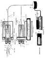
- FIG. 1is a plan view of an illustrative example of a connectorized optical component misalignment detection system.
- FIG. 2is a side view of the system of FIG. 1.
- FIG. 3is the system of FIG. 1 with the fiber ferrule inserted in the bore of a receptacle holding an optical component.
- FIG. 4is the system of FIG. 1 set up for a deviation of alignment function.
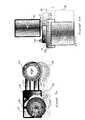
- FIGS. 5 a and 5 bshow the plan and side views, respectively, of a rotating lateral force mechanism.
- FIGS. 6 a and 6 bare diagrams of the rotating force vector and the relationship of the various force vectors.
- FIG. 7is an arrangement for measuring total output power of a component in a receptacle.
- FIG. 1shows an illustrative example of an application of the invention.
- An optical component 11is inserted into a receptacle 12 .
- Optical component 11may be a light source such as a vertical cavity surface emitting laser (VCSEL) or the like, or it may be a photo detector.
- Receptacle 12may be molded from plastic or other material.
- Component 11may be glued into an opening fitted for that kind of component. The glue may be on epoxy or other adequate adhering substance.
- At the other end of receptacle 12may be a bored round opening 13 which is fitted to receive an optical fiber ferrule 14 . Opening 13 could be square or any other shape. Ferrule 14 may fit in opening or bore 13 somewhat precise and snug.
- Ferrule 14may be easily removable from bore 13 .
- Ferrule 14is typically made from a ceramic material and may be available as part of fiber 16 for purchase in the market place.
- An end face 15 of ferrule 14when inserted, faces component 11 .
- In the center of ferrule 14there may be a small opening in which an end of the optical fiber 16 may be present.
- Ferrule 14may be fitted on or in and attached to a metal shaft or tube 17 .
- At the connection of ferrule 14 and tube 17may be situated a metal nut or ring 18 .
- Shaft 17may be press-fitted into nut 18 .
- Shaft 17may be made or machined from steel or other metal or material.
- nut 18may be made or machined from steel or other metal or material.
- Through the center of shaft 17may be a hole that holds or houses fiber 16 .
- Strain relief 19may be of a plastic, rubber or like flexible material. Strain relief 19 may help prevent fiber 16 from being overly bent or broken under movement. Parts 14 , 16 , 17 and 19 may be purchased as a combined assembly available in the market place.
- Ferrule 14may have a bare fiber core of fiber 16 at about the center of the face of ferrule 14 facing bore 13 .
- the face of ferrule 14may be ceramic as well as the rest of the ferrule except that a small hole in the face allows for exposure of an end of the bare fiber core.
- An instance of the diameter of the optical fiber coremay be about 50 microns or 62.5 microns.
- the core of fiber 16may be aligned with a small emitting or detecting area of component 11 . This area could be as small as or smaller than the area of the end of the fiber core.
- Fiber 16may have a cladding around its core which may result in the fiber having a diameter of about 125 microns. To protect the fiber more and provide durability, fiber 16 may also have a protective sheath around it.
- a fiber 16 support block or cylinder 20that has an opening which is clamped on and around nut 18 .
- Cylinder 20contains shaft 17 , relief 19 and optical fiber 16 .
- Around cylinder 20 towards the end on nut 18is a groove in which a retaining ring 21 may be inserted or snapped into place.
- Slipped on to cylinder 20 from the end opposite of nut 18may be a support spring 22 .
- Spring 22may be against retaining ring 21 , which prevents spring 22 from slipping past it to the end of cylinder 20 at nut 18 .
- against the other end of spring 22may be a bracket 23 . As bracket 23 is moved towards spring 22 and cylinder 20 remains stationary, bracket 23 may compress spring 22 .
- Attached to bracket 23may be a pneumatic ball slide 24 which can move bracket 23 toward spring 22 , as shown in FIG. 2. If cylinder 20 is free to move, slide 24 via bracket 23 and spring 22 may move cylinder 20 along with ferrule 14 of fiber 16 in a “z” direction towards receptacle 12 and ferrule 14 is pushed into bore 13 of receptacle 12 as shown in FIG. 3. Ferrule 14 is held in receptacle 12 with a constant force in the z direction. Spring 22 provides a cushion between bracket 23 and cylinder 20 . This cushion effect may prevent possible breakage of ferrule 14 or receptacle 12 upon their coming together. With this constant “z” force, there is no force that is orthogonal to the z direction being applied to cylinder 20 and ferrule 14 . The stopping point for ferrule 14 is the end of the bore in receptacle 12 .
- FIG. 4a mechanism for applying in x and y directions (orthogonal to the z direction) forces to ferrule 14 in bore 13 of receptacle 12 is illustrated by way of an example.
- a mechanical ring-like grip 25Fixed around cylinder 20 .
- Attached to grip 25is a block 26 via bar links 27 , as shown in FIGS. 5 a and 5 b .
- Block 26has a hole 28 having a shape of a nearly perfect circle.
- a motor 29Positioned proximate to block 26 is a motor 29 .
- Motor 29is situated with its shaft 30 at the center of circular hole 28 .
- the motor shaft 30may be aligned with a center axis 32 (FIG. 4).
- a connecting rod or bar 31Connected to shaft 30 is a connecting rod or bar 31 .
- On rod or bar 31is a plug, pin, slider roller or slider, roller or plug 33 that rides on or slides against an inside surface of circular hole 28 .
- Pin or plug 33moves block 26 a slight distance or the center of hole 28 off center axis 32 by a small amount of distance, for example, about one eighth of an inch, i.e., about 3 millimeters.
- Hole 28may be about one inch in diameter. The small amount of distance that block 26 is shifted in a direction that rotates in a circle relative to the z direction or center axis 32 .
- This movementtranslates in to a force 34 that has a direction orthogonal to center axis 32 or z direction.
- Plug 33may be removed from its hole or slot in connecting rod or bar 31 and placed in another hole or slot of rod or bar 31 to provide an adjustment of the amount of movement or resultant force 34 .
- a block 26 with a smaller or large hole 28may be utilized for block 26 or force 34 adjustment.
- Force 34causes ceramic ferrule 14 in hole or bore 13 to wiggle. There is a deviation axis 35 of tilt or wiggle of ferrule 14 , shaft 17 and cylinder 20 that may occur relative to center axis 32 of component 11 , receptacle 12 and bore 13 .
- This deviation 40may be about several mils at the base of receptacle 12 furthest from ferrule 14 .
- Deviation axis 35may be aligned or coincide with axis 32 when there is no force 34 and no tilt or wiggle of ferrule 14 along with its associated parts such as shaft 17 and cylinder 20 .
- FIG. 5 areveals a top view of the motor 29 and block 26 assembly relative to cylinder 20 .
- FIG. 5 breveals a side view of the motor 29 and block 26 assembly. Alternate shifted position 36 of block 26 , hole 28 and cylinder 20 is shown from the top in FIG. 5 a and from the side in FIG. 5 b , due to rotation of connecting rod 31 and plug 33 against the inside surface of hole 28 . Parts 26 , 28 and 20 shift around in a rather small circle relative to the nearly perfectly machined circle of the inside wall of hole 28 .
- the amount of deviation of axis 35is set by hole 28 , the hole 28 center and diameter, and the center position of motor shaft 30 relative to axis 32 , and the distance of plug 33 on connecting rod 31 from the center of motor shaft 30 . These dimensions and settings are selected with design calculations and a series of trials with various ferrules, receptacles and components.
- FIGS. 6 a and 6 bare vector diagrams showing the forces applied to ferrule 14 via cylinder 20 , grip 25 , bar 27 and block 26 , and retainer 21 , spring 22 , bracket 23 and pneumatic ball slide 24 .
- Forces orthogonal to the z directionare provided by force 34 vector that rotates about axis 32 .
- the force in the z directionmay be regarded as a force 37 .
- the z directionmay coincide with center axis 32 .
- Force 34may be in an x or y direction or somewhere in between.
- the direction of force 34may be dynamic as its vector rotates.
- Component 11may be a source of radiated power or it may be a detector of radiation.
- component 11may be an optical power source such as a vertical cavity surface emitting laser and medium 16 may be an optical fiber.
- various power readingsmay be taken.
- receptacle 12with component 11 inserted firmly in place, may be placed with bore 13 adjacent to a photo detector 41 in FIG. 7. This detector may be a NewportTM brand or like product.
- the output of photodetector 41may be connected to an optical power meter or source measure unit 39 .
- Power meter 39may be a NewportTM model Optical Power Meter 1830 -C or a KeithleyTM Source Meter, or the like. This measurement may be regarded as output power test. This test is performed with a particular current applied to component 11 . It may be mainly to determine what power component 11 is capable of when sourced at the particular current. This output measurement may be regarded as the “total output power.” Different detectors may be used to make the various measurements to possibly save time, or the same detector may be used to make the various measurements in attempt to minimize an amount of hardware used.
- ferrule 14may be inserted into bore 13 of receptacle 12 .
- Ferrule 14is maintained in bore 13 with an approximate force as provided by pneumatic ball slide 24 .
- the constant force 37may be in the z direction which is parallel with center axis 32 . There generally are virtually no forces orthogonal to force 37 .
- This arrangement of forcemay be applied to cylinder 20 and ferrule 14 for the duration of the test indicated here.
- the end of fiber 16 exiting cylinder 20may be coupled to a photodetector 38 which in turn has an output connected to optical power meter or source measure unit 39 . The same current, as used for the total output power test, may be used for this test.
- the testmeasures the power from component 11 through receptacle 12 , ferrule 14 and fiber 16 .
- the measured output from fiber 16may be regarded as the “output coupled power.”
- the constant z direction force 37 and absence of forces orthogonal to the direction of force 37may assure repeatability of tests with a constancy of results. With this setup, many other tests may be performed with a sweep that increments forward current of component 11 while measuring back monitor current of component 11 .
- the support box or cylinder 20may be held straight or parallel to axis 32 by bore 13 of receptacle 12 .
- Support spring 22may provide a cushion to assure that there is not an immediate overbearing force initially by ferrule 14 into bore 13 of receptacle 12 . Also, spring 22 may enable ferrule 14 to be fully inside bore 13 and enable support block or cylinder 20 to match any tilt bore 13 may have in order to make the test and its results repeatable.
- the third testmay be regarded for getting a measurement of “coupled power deviation”. This test may be used to detect gross misalignments between the fiber 16 end in ferrule 14 and the output or input of component 11 .
- the setup for this testmay be the same as the setup for the “output coupled power” test as noted above except along with the approximately constant force 37 being applied in the z direction on support block or cylinder 20 , a rotating force 34 is applied while ferrule 14 is held in place in bore 13 .
- cylinder 20 and ferrule 14wiggle or deviate around in a circular fashion as indicated by the deviation of axis 35 of cylinder 20 and ferrule 14 relative to center axis 32 of the bore 13 , receptacle 12 and component 11 combination.
- the end of fiber 16 from the end of cylinder 20 opposite of the end at ferrule 14may be coupled to photodetector 38 .
- the output of photodetector 38is input to an optical power meter, current meter, or source measure unit 39 which may provide a measurement of power from fiber 16 .
- a series or plurality of power measurementsmay be taken for instance as vector force 34 rotates about axis 32 .
- a maximum power measurementmay be selected from the series of power measurements and a minimum power measurement may be selected from the series of measurements.
- a ratio of the highest power measurement to the lowest power measurementmay be an indication of a “maximum coupled power deviation” between component 11 and fiber 16 . This may be in decibels (dB).
- a ratio of minimum power measurement to the total output power measurementmay indicate a “coupling efficiency” between component 11 and fiber 16 , defined as a percentage or in dB.
- a ratio of output coupled power at the particular current to the total output power at the same currentmay indicate a “simple coupling efficiency” between component 11 and fiber 16 . These ratios may provide various indications of alignment and misalignment. The above-noted tests, measurements, ratios and misalignment/alignment determinations may be performed manually, semi-automatically or automatically.
Landscapes
- Physics & Mathematics (AREA)
- General Physics & Mathematics (AREA)
- Optics & Photonics (AREA)
- Optical Couplings Of Light Guides (AREA)
Abstract
Description
- The invention pertains to connections and alignment of the respective components and the media connected to each other. Receptacles may be used for such connections. However, when components are aligned into receptacles, there are potential problems that may arise. There are problems of coupling of power and alignment of the optical component with its medium via a receptacle. This makes for an inefficient system.[0001]
- The present invention may provide verification and feedback on how poorly or effectively a component, e.g., a VCSEL device, is aligned by measuring medium-coupled power and measuring power a number of times while the medium such as a fiber is moved within the receptacle holding the component. This test may better assure the elimination of problems related to component, receptacle and medium connected assemblies. The component may instead be a detector.[0002]
- FIG. 1 is a plan view of an illustrative example of a connectorized optical component misalignment detection system.[0003]
- FIG. 2 is a side view of the system of FIG. 1.[0004]
- FIG. 3 is the system of FIG. 1 with the fiber ferrule inserted in the bore of a receptacle holding an optical component.[0005]
- FIG. 4 is the system of FIG. 1 set up for a deviation of alignment function.[0006]
- FIGS. 5[0007]aand5bshow the plan and side views, respectively, of a rotating lateral force mechanism.
- FIGS. 6[0008]aand6bare diagrams of the rotating force vector and the relationship of the various force vectors.
- FIG. 7 is an arrangement for measuring total output power of a component in a receptacle.[0009]
- FIG. 1 shows an illustrative example of an application of the invention. An[0010]
optical component 11 is inserted into areceptacle 12.Optical component 11 may be a light source such as a vertical cavity surface emitting laser (VCSEL) or the like, or it may be a photo detector.Receptacle 12 may be molded from plastic or other material.Component 11 may be glued into an opening fitted for that kind of component. The glue may be on epoxy or other adequate adhering substance. At the other end ofreceptacle 12 may be a bored round opening13 which is fitted to receive anoptical fiber ferrule 14.Opening 13 could be square or any other shape.Ferrule 14 may fit in opening or bore13 somewhat precise and snug. Yetferrule 14 may be easily removable frombore 13. Ferrule14 is typically made from a ceramic material and may be available as part offiber 16 for purchase in the market place. Anend face 15 offerrule 14, when inserted, facescomponent 11. In the center offerrule 14, there may be a small opening in which an end of theoptical fiber 16 may be present. There may be anopening 17 betweencomponent 11 and the inner surface ofbore 13 for the conveyance of radiation or light betweencomponent 11 andfiber 16 inferrule 14.Ferrule 14 may be fitted on or in and attached to a metal shaft ortube 17. At the connection offerrule 14 andtube 17 may be situated a metal nut orring 18. Shaft17 may be press-fitted intonut 18.Shaft 17 may be made or machined from steel or other metal or material. Likewise,nut 18 may be made or machined from steel or other metal or material. Through the center ofshaft 17 may be a hole that holds or housesfiber 16. On the other end ofshaft 17 opposite from thenut 18 andferrule 14 end may be attached astrain relief 19 which provides strain relief and protection foroptical fiber 16.Strain relief 19 may be of a plastic, rubber or like flexible material.Strain relief 19 may help preventfiber 16 from being overly bent or broken under movement.Parts - Ferrule[0011]14 may have a bare fiber core of
fiber 16 at about the center of the face offerrule 14 facingbore 13. The face offerrule 14 may be ceramic as well as the rest of the ferrule except that a small hole in the face allows for exposure of an end of the bare fiber core. An instance of the diameter of the optical fiber core may be about 50 microns or 62.5 microns. The core offiber 16 may be aligned with a small emitting or detecting area ofcomponent 11. This area could be as small as or smaller than the area of the end of the fiber core. Fiber16 may have a cladding around its core which may result in the fiber having a diameter of about 125 microns. To protect the fiber more and provide durability,fiber 16 may also have a protective sheath around it. - Formed, machined or made from steel or other metal or material may be a[0012]
fiber 16 support block orcylinder 20 that has an opening which is clamped on and aroundnut 18. At the other end ofcylinder 20 may be a hole through whichfiber 16 is threaded.Cylinder 20 containsshaft 17,relief 19 andoptical fiber 16. Aroundcylinder 20 towards the end onnut 18, is a groove in which aretaining ring 21 may be inserted or snapped into place. Slipped on tocylinder 20 from the end opposite ofnut 18 may be asupport spring 22.Spring 22 may be against retainingring 21, which preventsspring 22 from slipping past it to the end ofcylinder 20 atnut 18. Against the other end ofspring 22 may be abracket 23. Asbracket 23 is moved towardsspring 22 andcylinder 20 remains stationary,bracket 23 may compressspring 22. - Attached to[0013]
bracket 23 may be apneumatic ball slide 24 which can movebracket 23 towardspring 22, as shown in FIG. 2. Ifcylinder 20 is free to move, slide24 viabracket 23 andspring 22 may movecylinder 20 along withferrule 14 offiber 16 in a “z” direction towardsreceptacle 12 andferrule 14 is pushed intobore 13 ofreceptacle 12 as shown in FIG. 3. Ferrule14 is held inreceptacle 12 with a constant force in the z direction.Spring 22 provides a cushion betweenbracket 23 andcylinder 20. This cushion effect may prevent possible breakage offerrule 14 orreceptacle 12 upon their coming together. With this constant “z” force, there is no force that is orthogonal to the z direction being applied tocylinder 20 andferrule 14. The stopping point forferrule 14 is the end of the bore inreceptacle 12. - In FIG. 4, a mechanism for applying in x and y directions (orthogonal to the z direction) forces to ferrule[0014]14 in
bore 13 ofreceptacle 12 is illustrated by way of an example. Near the end ofcylinder 20 opposite from the end atferrule 14, is a mechanical ring-like grip 25 fixed aroundcylinder 20. Attached to grip25 is ablock 26 viabar links 27, as shown in FIGS. 5aand5b.Block 26 has ahole 28 having a shape of a nearly perfect circle. Positioned proximate to block26 is amotor 29.Motor 29 is situated with itsshaft 30 at the center ofcircular hole 28. Without any orthogonal forces applied in the x and y directions, themotor shaft 30 may be aligned with a center axis32 (FIG. 4). Connected toshaft 30 is a connecting rod or bar31. On rod or bar31 is a plug, pin, slider roller or slider, roller or plug33 that rides on or slides against an inside surface ofcircular hole 28. Pin or plug33 moves block26 a slight distance or the center ofhole 28 offcenter axis 32 by a small amount of distance, for example, about one eighth of an inch, i.e., about 3 millimeters.Hole 28 may be about one inch in diameter. The small amount of distance that block26 is shifted in a direction that rotates in a circle relative to the z direction orcenter axis 32. This movement translates in to aforce 34 that has a direction orthogonal to centeraxis 32 or z direction.Plug 33 may be removed from its hole or slot in connecting rod or bar31 and placed in another hole or slot of rod or bar31 to provide an adjustment of the amount of movement orresultant force 34. Likewise, ablock 26 with a smaller orlarge hole 28 may be utilized forblock 26 orforce 34 adjustment.Force 34 causesceramic ferrule 14 in hole or bore13 to wiggle. There is a deviation axis35 of tilt or wiggle offerrule 14,shaft 17 andcylinder 20 that may occur relative tocenter axis 32 ofcomponent 11,receptacle 12 and bore13. Thisdeviation 40 may be about several mils at the base ofreceptacle 12 furthest fromferrule 14. Deviation axis35 may be aligned or coincide withaxis 32 when there is noforce 34 and no tilt or wiggle offerrule 14 along with its associated parts such asshaft 17 andcylinder 20. - FIG. 5[0015]areveals a top view of the
motor 29 and block26 assembly relative tocylinder 20. FIG. 5breveals a side view of themotor 29 and block26 assembly. Alternate shiftedposition 36 ofblock 26,hole 28 andcylinder 20 is shown from the top in FIG. 5aand from the side in FIG. 5b, due to rotation of connecting rod31 and plug33 against the inside surface ofhole 28.Parts hole 28. The amount of deviation of axis35 is set byhole 28, thehole 28 center and diameter, and the center position ofmotor shaft 30 relative toaxis 32, and the distance ofplug 33 on connecting rod31 from the center ofmotor shaft 30. These dimensions and settings are selected with design calculations and a series of trials with various ferrules, receptacles and components. - FIGS. 6[0016]aand6bare vector diagrams showing the forces applied to ferrule14 via
cylinder 20,grip 25,bar 27 andblock 26, andretainer 21,spring 22,bracket 23 andpneumatic ball slide 24. Forces orthogonal to the z direction are provided byforce 34 vector that rotates aboutaxis 32. The force in the z direction may be regarded as aforce 37. The z direction may coincide withcenter axis 32.Force 34 may be in an x or y direction or somewhere in between. The direction offorce 34 may be dynamic as its vector rotates. - The purposes of the above-described structure and force dynamics are the determining alignment of a connectorized optical component with its optical media.[0017]
Component 11 may be a source of radiated power or it may be a detector of radiation. For purposes of illustrating the present invention,component 11 may be an optical power source such as a vertical cavity surface emitting laser and medium16 may be an optical fiber. To determine alignment properties, various power readings may be taken. First,receptacle 12, withcomponent 11 inserted firmly in place, may be placed withbore 13 adjacent to aphoto detector 41 in FIG. 7. This detector may be a Newport™ brand or like product. The output ofphotodetector 41 may be connected to an optical power meter orsource measure unit 39.Power meter 39 may be a Newport™ model Optical Power Meter1830-C or a Keithley™ Source Meter, or the like. This measurement may be regarded as output power test. This test is performed with a particular current applied tocomponent 11. It may be mainly to determine whatpower component 11 is capable of when sourced at the particular current. This output measurement may be regarded as the “total output power.” Different detectors may be used to make the various measurements to possibly save time, or the same detector may be used to make the various measurements in attempt to minimize an amount of hardware used. - Second,[0018]
ferrule 14 may be inserted intobore 13 ofreceptacle 12. (FIGS. 2 and 4.)Ferrule 14 is maintained inbore 13 with an approximate force as provided bypneumatic ball slide 24. Theconstant force 37 may be in the z direction which is parallel withcenter axis 32. There generally are virtually no forces orthogonal to force37. This arrangement of force may be applied tocylinder 20 andferrule 14 for the duration of the test indicated here. The end offiber 16 exitingcylinder 20 may be coupled to aphotodetector 38 which in turn has an output connected to optical power meter orsource measure unit 39. The same current, as used for the total output power test, may be used for this test. The test measures the power fromcomponent 11 throughreceptacle 12,ferrule 14 andfiber 16. The measured output fromfiber 16 may be regarded as the “output coupled power.” The constantz direction force 37 and absence of forces orthogonal to the direction offorce 37 may assure repeatability of tests with a constancy of results. With this setup, many other tests may be performed with a sweep that increments forward current ofcomponent 11 while measuring back monitor current ofcomponent 11. The support box orcylinder 20 may be held straight or parallel toaxis 32 bybore 13 ofreceptacle 12.Support spring 22 may provide a cushion to assure that there is not an immediate overbearing force initially byferrule 14 intobore 13 ofreceptacle 12. Also,spring 22 may enableferrule 14 to be fully inside bore13 and enable support block orcylinder 20 to match any tilt bore13 may have in order to make the test and its results repeatable. - The third test may be regarded for getting a measurement of “coupled power deviation”. This test may be used to detect gross misalignments between the[0019]
fiber 16 end inferrule 14 and the output or input ofcomponent 11. The setup for this test may be the same as the setup for the “output coupled power” test as noted above except along with the approximatelyconstant force 37 being applied in the z direction on support block orcylinder 20, a rotatingforce 34 is applied whileferrule 14 is held in place inbore 13. - As[0020]
forces cylinder 20 andferrule 14 wiggle or deviate around in a circular fashion as indicated by the deviation of axis35 ofcylinder 20 andferrule 14 relative to centeraxis 32 of thebore 13,receptacle 12 andcomponent 11 combination. The same particular current or different currents, depending upon test conditions or circumstances, as used in the tests for total output power and output coupled power, are applied tocomponent 11. The end offiber 16 from the end ofcylinder 20 opposite of the end atferrule 14, may be coupled tophotodetector 38. The output ofphotodetector 38 is input to an optical power meter, current meter, orsource measure unit 39 which may provide a measurement of power fromfiber 16. During this test, a series or plurality of power measurements may be taken for instance asvector force 34 rotates aboutaxis 32. A maximum power measurement may be selected from the series of power measurements and a minimum power measurement may be selected from the series of measurements. - A ratio of the highest power measurement to the lowest power measurement may be an indication of a “maximum coupled power deviation” between[0021]
component 11 andfiber 16. This may be in decibels (dB). A ratio of minimum power measurement to the total output power measurement may indicate a “coupling efficiency” betweencomponent 11 andfiber 16, defined as a percentage or in dB. - A ratio of output coupled power at the particular current to the total output power at the same current may indicate a “simple coupling efficiency” between[0022]
component 11 andfiber 16. These ratios may provide various indications of alignment and misalignment. The above-noted tests, measurements, ratios and misalignment/alignment determinations may be performed manually, semi-automatically or automatically. - Although the invention has been described with respect to at least one illustrative embodiment, many variations and modifications will become apparent to those skilled in the art upon reading the present specification. It is therefore the intention that the appended claims be interpreted as broadly as possible in view of the prior art to include all such variations and modifications.[0023]
Claims (50)
Priority Applications (1)
| Application Number | Priority Date | Filing Date | Title |
|---|---|---|---|
| US10/430,941US20040222363A1 (en) | 2003-05-07 | 2003-05-07 | Connectorized optical component misalignment detection system |
Applications Claiming Priority (1)
| Application Number | Priority Date | Filing Date | Title |
|---|---|---|---|
| US10/430,941US20040222363A1 (en) | 2003-05-07 | 2003-05-07 | Connectorized optical component misalignment detection system |
Publications (1)
| Publication Number | Publication Date |
|---|---|
| US20040222363A1true US20040222363A1 (en) | 2004-11-11 |
Family
ID=33416351
Family Applications (1)
| Application Number | Title | Priority Date | Filing Date |
|---|---|---|---|
| US10/430,941AbandonedUS20040222363A1 (en) | 2003-05-07 | 2003-05-07 | Connectorized optical component misalignment detection system |
Country Status (1)
| Country | Link |
|---|---|
| US (1) | US20040222363A1 (en) |
Citations (95)
| Publication number | Priority date | Publication date | Assignee | Title |
|---|---|---|---|---|
| US4317085A (en)* | 1979-09-12 | 1982-02-23 | Xerox Corporation | Channeled mesa laser |
| US4466694A (en)* | 1978-06-15 | 1984-08-21 | Her Majesty The Queen In Right Of Canada, As Represented By The Minister Of National Defence Of Her Majesty's Canadian Government | Wavelength selective optical coupler |
| US4660207A (en)* | 1984-11-21 | 1987-04-21 | Northern Telecom Limited | Surface-emitting light emitting device |
| US4675058A (en)* | 1983-12-14 | 1987-06-23 | Honeywell Inc. | Method of manufacturing a high-bandwidth, high radiance, surface emitting LED |
| US4868361A (en)* | 1988-04-01 | 1989-09-19 | General Electric Company | Coupling device for high power laser beam transmitting optical fibers |
| US4901327A (en)* | 1988-10-24 | 1990-02-13 | General Dynamics Corporation, Electronics Division | Transverse injection surface emitting laser |
| US4943970A (en)* | 1988-10-24 | 1990-07-24 | General Dynamics Corporation, Electronics Division | Surface emitting laser |
| US4956844A (en)* | 1989-03-17 | 1990-09-11 | Massachusetts Institute Of Technology | Two-dimensional surface-emitting laser array |
| US5031187A (en)* | 1990-02-14 | 1991-07-09 | Bell Communications Research, Inc. | Planar array of vertical-cavity, surface-emitting lasers |
| US5052016A (en)* | 1990-05-18 | 1991-09-24 | University Of New Mexico | Resonant-periodic-gain distributed-feedback surface-emitting semiconductor laser |
| US5079774A (en)* | 1990-12-27 | 1992-01-07 | International Business Machines Corporation | Polarization-tunable optoelectronic devices |
| US5115442A (en)* | 1990-04-13 | 1992-05-19 | At&T Bell Laboratories | Top-emitting surface emitting laser structures |
| US5117469A (en)* | 1991-02-01 | 1992-05-26 | Bell Communications Research, Inc. | Polarization-dependent and polarization-diversified opto-electronic devices using a strained quantum well |
| US5140605A (en)* | 1991-06-27 | 1992-08-18 | Xerox Corporation | Thermally stabilized diode laser structure |
| US5212706A (en)* | 1991-12-03 | 1993-05-18 | University Of Connecticut | Laser diode assembly with tunnel junctions and providing multiple beams |
| US5216680A (en)* | 1991-07-11 | 1993-06-01 | Board Of Regents, The University Of Texas System | Optical guided-mode resonance filter |
| US5216263A (en)* | 1990-11-29 | 1993-06-01 | Xerox Corporation | High density, independently addressable, surface emitting semiconductor laser-light emitting diode arrays |
| US5237581A (en)* | 1990-11-14 | 1993-08-17 | Nec Corporation | Semiconductor multilayer reflector and light emitting device with the same |
| US5245622A (en)* | 1992-05-07 | 1993-09-14 | Bandgap Technology Corporation | Vertical-cavity surface-emitting lasers with intra-cavity structures |
| US5285466A (en)* | 1992-05-20 | 1994-02-08 | Wisconsin Alumni Research Foundation | Feedback mechanism for vertical cavity surface emitting lasers |
| US5293392A (en)* | 1992-07-31 | 1994-03-08 | Motorola, Inc. | Top emitting VCSEL with etch stop layer |
| US5317587A (en)* | 1992-08-06 | 1994-05-31 | Motorola, Inc. | VCSEL with separate control of current distribution and optical mode |
| US5325386A (en)* | 1992-04-21 | 1994-06-28 | Bandgap Technology Corporation | Vertical-cavity surface emitting laser assay display system |
| US5331654A (en)* | 1993-03-05 | 1994-07-19 | Photonics Research Incorporated | Polarized surface-emitting laser |
| US5337074A (en)* | 1990-12-28 | 1994-08-09 | Xerox Corporation | Opto-electronic line printer having a high density, independently addressable, surface emitting semiconductor laser/light emitting diode array |
| US5337183A (en)* | 1991-02-01 | 1994-08-09 | Yeda Research And Development Co. Ltd. | Distributed resonant cavity light beam modulator |
| US5349599A (en)* | 1990-03-29 | 1994-09-20 | Larkins Eric C | Bistable optical laser based on a heterostructure PNPN thyristor |
| US5351256A (en)* | 1993-04-28 | 1994-09-27 | The United States Of America As Represented By The United States Department Of Energy | Electrically injected visible vertical cavity surface emitting laser diodes |
| US5386426A (en)* | 1992-09-10 | 1995-01-31 | Hughes Aircraft Company | Narrow bandwidth laser array system |
| US5390209A (en)* | 1994-01-05 | 1995-02-14 | At&T Corp. | Article comprising a semiconductor laser that is non-degenerate with regard to polarization |
| US5396508A (en)* | 1992-09-22 | 1995-03-07 | Xerox Corporation | Polarization switchable quantum well laser |
| US5404373A (en)* | 1991-11-08 | 1995-04-04 | University Of New Mexico | Electro-optical device |
| US5412678A (en)* | 1992-09-22 | 1995-05-02 | Xerox Corporation | Multi-beam, orthogonally-polarized emitting monolithic quantum well lasers |
| US5412680A (en)* | 1994-03-18 | 1995-05-02 | Photonics Research Incorporated | Linear polarization of semiconductor laser |
| US5428634A (en)* | 1992-11-05 | 1995-06-27 | The United States Of America As Represented By The United States Department Of Energy | Visible light emitting vertical cavity surface emitting lasers |
| US5438584A (en)* | 1992-09-22 | 1995-08-01 | Xerox Corporation | Dual polarization laser diode with quaternary material system |
| US5446754A (en)* | 1993-11-05 | 1995-08-29 | Photonics Research Incorporated | Phased array semiconductor laser |
| US5493577A (en)* | 1994-12-21 | 1996-02-20 | Sandia Corporation | Efficient semiconductor light-emitting device and method |
| US5497390A (en)* | 1992-01-31 | 1996-03-05 | Nippon Telegraph And Telephone Corporation | Polarization mode switching semiconductor laser apparatus |
| US5513202A (en)* | 1994-02-25 | 1996-04-30 | Matsushita Electric Industrial Co., Ltd. | Vertical-cavity surface-emitting semiconductor laser |
| US5530715A (en)* | 1994-11-29 | 1996-06-25 | Motorola, Inc. | Vertical cavity surface emitting laser having continuous grading |
| US5555255A (en)* | 1992-12-03 | 1996-09-10 | Siemens Aktiengesellschaft | Surface-emitting laser diode |
| US5557626A (en)* | 1994-06-15 | 1996-09-17 | Motorola | Patterned mirror VCSEL with adjustable selective etch region |
| US5598300A (en)* | 1995-06-05 | 1997-01-28 | Board Of Regents, The University Of Texas System | Efficient bandpass reflection and transmission filters with low sidebands based on guided-mode resonance effects |
| US5606572A (en)* | 1994-03-24 | 1997-02-25 | Vixel Corporation | Integration of laser with photodiode for feedback control |
| US5625729A (en)* | 1994-08-12 | 1997-04-29 | Brown; Thomas G. | Optoelectronic device for coupling between an external optical wave and a local optical wave for optical modulators and detectors |
| US5642376A (en)* | 1991-11-07 | 1997-06-24 | Vixel Corporation | Visible light surface emitting semiconductor laser |
| US5645462A (en)* | 1991-10-08 | 1997-07-08 | Canon Kabushiki Kaisha | Electron-emitting device, and electron beam-generating apparatus and image-forming apparatus employing the device |
| US5646978A (en)* | 1995-04-27 | 1997-07-08 | Lucent Technologies Inc. | Method and apparatus for providing interswitch handover in personal communication services systems |
| US5648978A (en)* | 1995-01-04 | 1997-07-15 | Canon Kabushiki Kaisha | Oscillation polarization mode selective semiconductor laser, modulation method therefor and optical communication system using the same |
| US5712188A (en)* | 1995-12-21 | 1998-01-27 | Electronics And Telecommunications Research Institute | Fabrication method of polarization-controlled surface-emitting laser diode using tilted-cavity |
| US5727013A (en)* | 1995-10-27 | 1998-03-10 | Wisconsin Alumni Research Foundation | Single lobe surface emitting complex coupled distributed feedback semiconductor laser |
| US5726805A (en)* | 1996-06-25 | 1998-03-10 | Sandia Corporation | Optical filter including a sub-wavelength periodic structure and method of making |
| US5727014A (en)* | 1995-10-31 | 1998-03-10 | Hewlett-Packard Company | Vertical-cavity surface-emitting laser generating light with a defined direction of polarization |
| US5774487A (en)* | 1996-10-16 | 1998-06-30 | Honeywell Inc. | Filamented multi-wavelength vertical-cavity surface emitting laser |
| US5778018A (en)* | 1994-10-13 | 1998-07-07 | Nec Corporation | VCSELs (vertical-cavity surface emitting lasers) and VCSEL-based devices |
| US5781575A (en)* | 1993-09-10 | 1998-07-14 | Telefonaktiebolaget Lm Ericsson | Surface emitting laser device with a vertical cavity |
| US5784399A (en)* | 1996-12-19 | 1998-07-21 | Xerox Corporation | Polarization mode selection by distributed Bragg reflector in a quantum well laser |
| US5805624A (en)* | 1996-07-30 | 1998-09-08 | Hewlett-Packard Company | Long-wavelength infra-red vertical cavity surface-emitting laser on a gallium arsenide substrate |
| US5892784A (en)* | 1994-10-27 | 1999-04-06 | Hewlett-Packard Company | N-drive p-common surface emitting laser fabricated on n+ substrate |
| US5892787A (en)* | 1994-10-27 | 1999-04-06 | Hewlett-Packard Company | N-drive, p-common light-emitting devices fabricated on an n-type substrate and method of making same |
| US5896408A (en)* | 1997-08-15 | 1999-04-20 | Hewlett-Packard Company | Near planar native-oxide VCSEL devices and arrays using converging oxide ringlets |
| US5901166A (en)* | 1994-02-18 | 1999-05-04 | Canon Kabushiki Kaisha | Oscillation polarization mode selective semiconductor laser, light transmitter and optical communication system using the laser |
| US5903588A (en)* | 1997-03-06 | 1999-05-11 | Honeywell Inc. | Laser with a selectively changed current confining layer |
| US5903589A (en)* | 1995-12-18 | 1999-05-11 | Picolight, Incorporated | Oxidizable semiconductor device having cavities which allow for improved oxidation of the semiconductor device |
| US5903590A (en)* | 1996-05-20 | 1999-05-11 | Sandia Corporation | Vertical-cavity surface-emitting laser device |
| US5908408A (en)* | 1996-09-13 | 1999-06-01 | Mcgary; R. Kern | Non-reusable retractable safety syringe |
| US5936266A (en)* | 1997-07-22 | 1999-08-10 | The Board Of Trustees Of The University Of Illinois | Semiconductor devices and methods with tunnel contact hole sources |
| US5940422A (en)* | 1996-06-28 | 1999-08-17 | Honeywell Inc. | Laser with an improved mode control |
| US6043104A (en)* | 1996-08-28 | 2000-03-28 | Canon Kabushiki Kaisha | Fabrication method of a polarization selective semiconductor laser |
| US6046065A (en)* | 1996-09-13 | 2000-04-04 | Alcatel | Process for fabricating a semiconductor opto-electronic component and component and matrix of components fabricated by this process |
| US6052398A (en)* | 1997-04-03 | 2000-04-18 | Alcatel | Surface emitting semiconductor laser |
| US6055262A (en)* | 1997-06-11 | 2000-04-25 | Honeywell Inc. | Resonant reflector for improved optoelectronic device performance and enhanced applicability |
| US6060743A (en)* | 1997-05-21 | 2000-05-09 | Kabushiki Kaisha Toshiba | Semiconductor memory device having multilayer group IV nanocrystal quantum dot floating gate and method of manufacturing the same |
| US6078601A (en)* | 1997-03-07 | 2000-06-20 | Smith; David F. | Method for controlling the operation of a laser |
| US6086263A (en)* | 1996-06-13 | 2000-07-11 | 3M Innovative Properties Company | Active device receptacle |
| US6185241B1 (en)* | 1998-10-29 | 2001-02-06 | Xerox Corporation | Metal spatial filter to enhance model reflectivity in a vertical cavity surface emitting laser |
| US6191890B1 (en)* | 1996-03-29 | 2001-02-20 | Interuniversitair Micro-Elektronica Centrum Vzw | Optical system with a dielectric subwavelength structure having high reflectivity and polarization selectivity |
| US6208681B1 (en)* | 1997-02-07 | 2001-03-27 | Xerox Corporation | Highly compact vertical cavity surface emitting lasers |
| US6212312B1 (en)* | 1999-09-17 | 2001-04-03 | U.T. Battelle, Llc | Optical multiplexer/demultiplexer using resonant grating filters |
| US6238944B1 (en)* | 1999-12-21 | 2001-05-29 | Xerox Corporation | Buried heterostructure vertical-cavity surface-emitting laser diodes using impurity induced layer disordering (IILD) via a buried impurity source |
| US20010004414A1 (en)* | 1999-12-13 | 2001-06-21 | Gerhard Kuhn | Coupling configuration |
| US6339496B1 (en)* | 1999-06-22 | 2002-01-15 | University Of Maryland | Cavity-less vertical semiconductor optical amplifier |
| US6369403B1 (en)* | 1999-05-27 | 2002-04-09 | The Board Of Trustees Of The University Of Illinois | Semiconductor devices and methods with tunnel contact hole sources and non-continuous barrier layer |
| US6372533B2 (en)* | 1998-11-05 | 2002-04-16 | Gore Enterprise Holdings, Inc. | Method of making a semiconductor device with aligned oxide apertures and contact to an intervening layer |
| US6392257B1 (en)* | 2000-02-10 | 2002-05-21 | Motorola Inc. | Semiconductor structure, semiconductor device, communicating device, integrated circuit, and process for fabricating the same |
| US6411638B1 (en)* | 1999-08-31 | 2002-06-25 | Honeywell Inc. | Coupled cavity anti-guided vertical-cavity surface-emitting laser |
| US6410941B1 (en)* | 2000-06-30 | 2002-06-25 | Motorola, Inc. | Reconfigurable systems using hybrid integrated circuits with optical ports |
| US6427066B1 (en)* | 2000-06-30 | 2002-07-30 | Motorola, Inc. | Apparatus and method for effecting communications among a plurality of remote stations |
| US6438288B1 (en)* | 2000-12-15 | 2002-08-20 | Lightap | Tunable optical filter system |
| US6515308B1 (en)* | 2001-12-21 | 2003-02-04 | Xerox Corporation | Nitride-based VCSEL or light emitting diode with p-n tunnel junction current injection |
| US6535541B1 (en)* | 1998-04-14 | 2003-03-18 | Bandwidth 9, Inc | Vertical cavity apparatus with tunnel junction |
| US6542531B2 (en)* | 2001-03-15 | 2003-04-01 | Ecole Polytechnique Federale De Lausanne | Vertical cavity surface emitting laser and a method of fabrication thereof |
| US20030072526A1 (en)* | 1998-09-22 | 2003-04-17 | Kathman Alan D. | Fiber coupler, system and associated methods for reducing back reflections |
| US6567435B1 (en)* | 1999-03-19 | 2003-05-20 | Optical Communication Products, Inc. | VCSEL power monitoring system using plastic encapsulation techniques |
- 2003
- 2003-05-07USUS10/430,941patent/US20040222363A1/ennot_activeAbandoned
Patent Citations (99)
| Publication number | Priority date | Publication date | Assignee | Title |
|---|---|---|---|---|
| US4466694A (en)* | 1978-06-15 | 1984-08-21 | Her Majesty The Queen In Right Of Canada, As Represented By The Minister Of National Defence Of Her Majesty's Canadian Government | Wavelength selective optical coupler |
| US4317085A (en)* | 1979-09-12 | 1982-02-23 | Xerox Corporation | Channeled mesa laser |
| US4675058A (en)* | 1983-12-14 | 1987-06-23 | Honeywell Inc. | Method of manufacturing a high-bandwidth, high radiance, surface emitting LED |
| US4660207A (en)* | 1984-11-21 | 1987-04-21 | Northern Telecom Limited | Surface-emitting light emitting device |
| US4868361A (en)* | 1988-04-01 | 1989-09-19 | General Electric Company | Coupling device for high power laser beam transmitting optical fibers |
| US4901327A (en)* | 1988-10-24 | 1990-02-13 | General Dynamics Corporation, Electronics Division | Transverse injection surface emitting laser |
| US4943970A (en)* | 1988-10-24 | 1990-07-24 | General Dynamics Corporation, Electronics Division | Surface emitting laser |
| US4956844A (en)* | 1989-03-17 | 1990-09-11 | Massachusetts Institute Of Technology | Two-dimensional surface-emitting laser array |
| US5031187A (en)* | 1990-02-14 | 1991-07-09 | Bell Communications Research, Inc. | Planar array of vertical-cavity, surface-emitting lasers |
| US5349599A (en)* | 1990-03-29 | 1994-09-20 | Larkins Eric C | Bistable optical laser based on a heterostructure PNPN thyristor |
| US5115442A (en)* | 1990-04-13 | 1992-05-19 | At&T Bell Laboratories | Top-emitting surface emitting laser structures |
| US5052016A (en)* | 1990-05-18 | 1991-09-24 | University Of New Mexico | Resonant-periodic-gain distributed-feedback surface-emitting semiconductor laser |
| US5237581A (en)* | 1990-11-14 | 1993-08-17 | Nec Corporation | Semiconductor multilayer reflector and light emitting device with the same |
| US5317170A (en)* | 1990-11-29 | 1994-05-31 | Xerox Corporation | High density, independently addressable, surface emitting semiconductor laser/light emitting diode arrays without a substrate |
| US5216263A (en)* | 1990-11-29 | 1993-06-01 | Xerox Corporation | High density, independently addressable, surface emitting semiconductor laser-light emitting diode arrays |
| US5079774A (en)* | 1990-12-27 | 1992-01-07 | International Business Machines Corporation | Polarization-tunable optoelectronic devices |
| US5337074A (en)* | 1990-12-28 | 1994-08-09 | Xerox Corporation | Opto-electronic line printer having a high density, independently addressable, surface emitting semiconductor laser/light emitting diode array |
| US5117469A (en)* | 1991-02-01 | 1992-05-26 | Bell Communications Research, Inc. | Polarization-dependent and polarization-diversified opto-electronic devices using a strained quantum well |
| US5337183A (en)* | 1991-02-01 | 1994-08-09 | Yeda Research And Development Co. Ltd. | Distributed resonant cavity light beam modulator |
| US5140605A (en)* | 1991-06-27 | 1992-08-18 | Xerox Corporation | Thermally stabilized diode laser structure |
| US5216680A (en)* | 1991-07-11 | 1993-06-01 | Board Of Regents, The University Of Texas System | Optical guided-mode resonance filter |
| US5645462A (en)* | 1991-10-08 | 1997-07-08 | Canon Kabushiki Kaisha | Electron-emitting device, and electron beam-generating apparatus and image-forming apparatus employing the device |
| US5642376A (en)* | 1991-11-07 | 1997-06-24 | Vixel Corporation | Visible light surface emitting semiconductor laser |
| US5404373A (en)* | 1991-11-08 | 1995-04-04 | University Of New Mexico | Electro-optical device |
| US5212706A (en)* | 1991-12-03 | 1993-05-18 | University Of Connecticut | Laser diode assembly with tunnel junctions and providing multiple beams |
| US5497390A (en)* | 1992-01-31 | 1996-03-05 | Nippon Telegraph And Telephone Corporation | Polarization mode switching semiconductor laser apparatus |
| US5325386A (en)* | 1992-04-21 | 1994-06-28 | Bandgap Technology Corporation | Vertical-cavity surface emitting laser assay display system |
| US5245622A (en)* | 1992-05-07 | 1993-09-14 | Bandgap Technology Corporation | Vertical-cavity surface-emitting lasers with intra-cavity structures |
| US5285466A (en)* | 1992-05-20 | 1994-02-08 | Wisconsin Alumni Research Foundation | Feedback mechanism for vertical cavity surface emitting lasers |
| US5293392A (en)* | 1992-07-31 | 1994-03-08 | Motorola, Inc. | Top emitting VCSEL with etch stop layer |
| US5317587A (en)* | 1992-08-06 | 1994-05-31 | Motorola, Inc. | VCSEL with separate control of current distribution and optical mode |
| US5386426A (en)* | 1992-09-10 | 1995-01-31 | Hughes Aircraft Company | Narrow bandwidth laser array system |
| US5412678A (en)* | 1992-09-22 | 1995-05-02 | Xerox Corporation | Multi-beam, orthogonally-polarized emitting monolithic quantum well lasers |
| US5438584A (en)* | 1992-09-22 | 1995-08-01 | Xerox Corporation | Dual polarization laser diode with quaternary material system |
| US5396508A (en)* | 1992-09-22 | 1995-03-07 | Xerox Corporation | Polarization switchable quantum well laser |
| US5428634A (en)* | 1992-11-05 | 1995-06-27 | The United States Of America As Represented By The United States Department Of Energy | Visible light emitting vertical cavity surface emitting lasers |
| US5555255A (en)* | 1992-12-03 | 1996-09-10 | Siemens Aktiengesellschaft | Surface-emitting laser diode |
| US5331654A (en)* | 1993-03-05 | 1994-07-19 | Photonics Research Incorporated | Polarized surface-emitting laser |
| US5351256A (en)* | 1993-04-28 | 1994-09-27 | The United States Of America As Represented By The United States Department Of Energy | Electrically injected visible vertical cavity surface emitting laser diodes |
| US5781575A (en)* | 1993-09-10 | 1998-07-14 | Telefonaktiebolaget Lm Ericsson | Surface emitting laser device with a vertical cavity |
| US5446754A (en)* | 1993-11-05 | 1995-08-29 | Photonics Research Incorporated | Phased array semiconductor laser |
| US5390209A (en)* | 1994-01-05 | 1995-02-14 | At&T Corp. | Article comprising a semiconductor laser that is non-degenerate with regard to polarization |
| US5901166A (en)* | 1994-02-18 | 1999-05-04 | Canon Kabushiki Kaisha | Oscillation polarization mode selective semiconductor laser, light transmitter and optical communication system using the laser |
| US5513202A (en)* | 1994-02-25 | 1996-04-30 | Matsushita Electric Industrial Co., Ltd. | Vertical-cavity surface-emitting semiconductor laser |
| US5412680A (en)* | 1994-03-18 | 1995-05-02 | Photonics Research Incorporated | Linear polarization of semiconductor laser |
| US5606572A (en)* | 1994-03-24 | 1997-02-25 | Vixel Corporation | Integration of laser with photodiode for feedback control |
| US5557626A (en)* | 1994-06-15 | 1996-09-17 | Motorola | Patterned mirror VCSEL with adjustable selective etch region |
| US5625729A (en)* | 1994-08-12 | 1997-04-29 | Brown; Thomas G. | Optoelectronic device for coupling between an external optical wave and a local optical wave for optical modulators and detectors |
| US5778018A (en)* | 1994-10-13 | 1998-07-07 | Nec Corporation | VCSELs (vertical-cavity surface emitting lasers) and VCSEL-based devices |
| US5892787A (en)* | 1994-10-27 | 1999-04-06 | Hewlett-Packard Company | N-drive, p-common light-emitting devices fabricated on an n-type substrate and method of making same |
| US5892784A (en)* | 1994-10-27 | 1999-04-06 | Hewlett-Packard Company | N-drive p-common surface emitting laser fabricated on n+ substrate |
| US5530715A (en)* | 1994-11-29 | 1996-06-25 | Motorola, Inc. | Vertical cavity surface emitting laser having continuous grading |
| US5493577A (en)* | 1994-12-21 | 1996-02-20 | Sandia Corporation | Efficient semiconductor light-emitting device and method |
| US5648978A (en)* | 1995-01-04 | 1997-07-15 | Canon Kabushiki Kaisha | Oscillation polarization mode selective semiconductor laser, modulation method therefor and optical communication system using the same |
| US5646978A (en)* | 1995-04-27 | 1997-07-08 | Lucent Technologies Inc. | Method and apparatus for providing interswitch handover in personal communication services systems |
| US5598300A (en)* | 1995-06-05 | 1997-01-28 | Board Of Regents, The University Of Texas System | Efficient bandpass reflection and transmission filters with low sidebands based on guided-mode resonance effects |
| US5727013A (en)* | 1995-10-27 | 1998-03-10 | Wisconsin Alumni Research Foundation | Single lobe surface emitting complex coupled distributed feedback semiconductor laser |
| US5727014A (en)* | 1995-10-31 | 1998-03-10 | Hewlett-Packard Company | Vertical-cavity surface-emitting laser generating light with a defined direction of polarization |
| US5903589A (en)* | 1995-12-18 | 1999-05-11 | Picolight, Incorporated | Oxidizable semiconductor device having cavities which allow for improved oxidation of the semiconductor device |
| US6269109B1 (en)* | 1995-12-18 | 2001-07-31 | Picolight Incorporated | Conductive element with lateral oxidation barrier |
| US6014395A (en)* | 1995-12-18 | 2000-01-11 | Picolight Incorporated | Oxidizable semiconductor device having cavities which allow for improved oxidation of the semiconductor device |
| US5712188A (en)* | 1995-12-21 | 1998-01-27 | Electronics And Telecommunications Research Institute | Fabrication method of polarization-controlled surface-emitting laser diode using tilted-cavity |
| US6191890B1 (en)* | 1996-03-29 | 2001-02-20 | Interuniversitair Micro-Elektronica Centrum Vzw | Optical system with a dielectric subwavelength structure having high reflectivity and polarization selectivity |
| US5903590A (en)* | 1996-05-20 | 1999-05-11 | Sandia Corporation | Vertical-cavity surface-emitting laser device |
| US6086263A (en)* | 1996-06-13 | 2000-07-11 | 3M Innovative Properties Company | Active device receptacle |
| US5726805A (en)* | 1996-06-25 | 1998-03-10 | Sandia Corporation | Optical filter including a sub-wavelength periodic structure and method of making |
| US5940422A (en)* | 1996-06-28 | 1999-08-17 | Honeywell Inc. | Laser with an improved mode control |
| US5805624A (en)* | 1996-07-30 | 1998-09-08 | Hewlett-Packard Company | Long-wavelength infra-red vertical cavity surface-emitting laser on a gallium arsenide substrate |
| US6043104A (en)* | 1996-08-28 | 2000-03-28 | Canon Kabushiki Kaisha | Fabrication method of a polarization selective semiconductor laser |
| US6046065A (en)* | 1996-09-13 | 2000-04-04 | Alcatel | Process for fabricating a semiconductor opto-electronic component and component and matrix of components fabricated by this process |
| US5908408A (en)* | 1996-09-13 | 1999-06-01 | Mcgary; R. Kern | Non-reusable retractable safety syringe |
| US5774487A (en)* | 1996-10-16 | 1998-06-30 | Honeywell Inc. | Filamented multi-wavelength vertical-cavity surface emitting laser |
| US5784399A (en)* | 1996-12-19 | 1998-07-21 | Xerox Corporation | Polarization mode selection by distributed Bragg reflector in a quantum well laser |
| US6208681B1 (en)* | 1997-02-07 | 2001-03-27 | Xerox Corporation | Highly compact vertical cavity surface emitting lasers |
| US5903588A (en)* | 1997-03-06 | 1999-05-11 | Honeywell Inc. | Laser with a selectively changed current confining layer |
| US6078601A (en)* | 1997-03-07 | 2000-06-20 | Smith; David F. | Method for controlling the operation of a laser |
| US6052398A (en)* | 1997-04-03 | 2000-04-18 | Alcatel | Surface emitting semiconductor laser |
| US6060743A (en)* | 1997-05-21 | 2000-05-09 | Kabushiki Kaisha Toshiba | Semiconductor memory device having multilayer group IV nanocrystal quantum dot floating gate and method of manufacturing the same |
| US6055262A (en)* | 1997-06-11 | 2000-04-25 | Honeywell Inc. | Resonant reflector for improved optoelectronic device performance and enhanced applicability |
| US5936266A (en)* | 1997-07-22 | 1999-08-10 | The Board Of Trustees Of The University Of Illinois | Semiconductor devices and methods with tunnel contact hole sources |
| US5896408A (en)* | 1997-08-15 | 1999-04-20 | Hewlett-Packard Company | Near planar native-oxide VCSEL devices and arrays using converging oxide ringlets |
| US6535541B1 (en)* | 1998-04-14 | 2003-03-18 | Bandwidth 9, Inc | Vertical cavity apparatus with tunnel junction |
| US20030072526A1 (en)* | 1998-09-22 | 2003-04-17 | Kathman Alan D. | Fiber coupler, system and associated methods for reducing back reflections |
| US6185241B1 (en)* | 1998-10-29 | 2001-02-06 | Xerox Corporation | Metal spatial filter to enhance model reflectivity in a vertical cavity surface emitting laser |
| US6372533B2 (en)* | 1998-11-05 | 2002-04-16 | Gore Enterprise Holdings, Inc. | Method of making a semiconductor device with aligned oxide apertures and contact to an intervening layer |
| US6567435B1 (en)* | 1999-03-19 | 2003-05-20 | Optical Communication Products, Inc. | VCSEL power monitoring system using plastic encapsulation techniques |
| US6369403B1 (en)* | 1999-05-27 | 2002-04-09 | The Board Of Trustees Of The University Of Illinois | Semiconductor devices and methods with tunnel contact hole sources and non-continuous barrier layer |
| US6339496B1 (en)* | 1999-06-22 | 2002-01-15 | University Of Maryland | Cavity-less vertical semiconductor optical amplifier |
| US6411638B1 (en)* | 1999-08-31 | 2002-06-25 | Honeywell Inc. | Coupled cavity anti-guided vertical-cavity surface-emitting laser |
| US6212312B1 (en)* | 1999-09-17 | 2001-04-03 | U.T. Battelle, Llc | Optical multiplexer/demultiplexer using resonant grating filters |
| US6536959B2 (en)* | 1999-12-13 | 2003-03-25 | Infineon Technologies Ag | Coupling configuration for connecting an optical fiber to an optoelectronic component |
| US20010004414A1 (en)* | 1999-12-13 | 2001-06-21 | Gerhard Kuhn | Coupling configuration |
| US6238944B1 (en)* | 1999-12-21 | 2001-05-29 | Xerox Corporation | Buried heterostructure vertical-cavity surface-emitting laser diodes using impurity induced layer disordering (IILD) via a buried impurity source |
| US6392257B1 (en)* | 2000-02-10 | 2002-05-21 | Motorola Inc. | Semiconductor structure, semiconductor device, communicating device, integrated circuit, and process for fabricating the same |
| US6410941B1 (en)* | 2000-06-30 | 2002-06-25 | Motorola, Inc. | Reconfigurable systems using hybrid integrated circuits with optical ports |
| US6427066B1 (en)* | 2000-06-30 | 2002-07-30 | Motorola, Inc. | Apparatus and method for effecting communications among a plurality of remote stations |
| US6438288B1 (en)* | 2000-12-15 | 2002-08-20 | Lightap | Tunable optical filter system |
| US6542531B2 (en)* | 2001-03-15 | 2003-04-01 | Ecole Polytechnique Federale De Lausanne | Vertical cavity surface emitting laser and a method of fabrication thereof |
| US6515308B1 (en)* | 2001-12-21 | 2003-02-04 | Xerox Corporation | Nitride-based VCSEL or light emitting diode with p-n tunnel junction current injection |
Similar Documents
| Publication | Publication Date | Title |
|---|---|---|
| JP6046030B2 (en) | Optical fiber alignment measurement method and apparatus | |
| JP2013522674A5 (en) | ||
| US6098297A (en) | Laser alignment tool | |
| US20150285722A1 (en) | Modular hardness testing machine | |
| US6956643B2 (en) | Apparatus and method for testing optical transceivers | |
| AU2006333352A1 (en) | Apparatus and methods for verifying an acceptable splice termination | |
| CN105223966B (en) | Device for positioning and aligning a rotationally symmetrical body | |
| US20110122401A1 (en) | Method and Apparatus For Verifying the Termination Quality of an Optical Fiber Interface in a Fiber Optic Cable Connector | |
| KR102000116B1 (en) | Assembly tool for vacuum pump bearing | |
| US7719667B2 (en) | Estimating loss of mechanical splices interconnecting optical fibers, and connector installation tool | |
| CN111765854A (en) | Angle inspection device and detection method for optical crystal | |
| FR2463387A1 (en) | METHOD FOR ADJUSTING THE POSITION OF THE PROBES OF A COMPARATOR OF THE BUFFER TYPE AND COMPARATOR FOR IMPLEMENTING SAID METHOD | |
| US20040222363A1 (en) | Connectorized optical component misalignment detection system | |
| US5574813A (en) | Optical fiber connector, abutment fixture and method of compatible use thereof | |
| EP2423660B1 (en) | Method and device for measuring the output angle of optical fiber | |
| JP2000261836A (en) | Method and device for calibrating optical probe assembly | |
| CN110864985A (en) | An Extensometer Alignment Adjustment Device for Creep Fatigue Testing Machine | |
| US12247830B2 (en) | Relative mode transmission loss measurement of a connectorized fiber optic cable | |
| US20050105876A1 (en) | Optic fiber terminus indexer | |
| US6004045A (en) | Optical connector | |
| CN212931291U (en) | Roundness detection device | |
| CN112797892B (en) | Optical fiber clamping mechanism and calibration method of optical fiber parameter testing equipment | |
| JP5939389B2 (en) | Photodetector | |
| CN109060208B (en) | Mechanical testing equipment and testing method using the same | |
| US7786441B2 (en) | Tensiographic drophead |
Legal Events
| Date | Code | Title | Description |
|---|---|---|---|
| AS | Assignment | Owner name:HONEYWELL INTERNATIONAL INC., NEW JERSEY Free format text:ASSIGNMENT OF ASSIGNORS INTEREST;ASSIGNORS:LALONDE, ANDRE R.;WILLIAMS, RICK S.;REEL/FRAME:014062/0704 Effective date:20030506 | |
| AS | Assignment | Owner name:FINISAR CORPORATION, CALIFORNIA Free format text:ASSIGNMENT OF ASSIGNORS INTEREST;ASSIGNOR:HONEYWELL INTERNATIONAL, INC.;REEL/FRAME:014468/0371 Effective date:20040301 Owner name:FINISAR CORPORATION, CALIFORNIA Free format text:ASSIGNMENT OF ASSIGNORS INTEREST;ASSIGNOR:HONEYWELL INTERNATIONAL, INC.;REEL/FRAME:014468/0407 Effective date:20040301 | |
| AS | Assignment | Owner name:FINISAR CORPORATION, CALIFORNIA Free format text:ASSIGNMENT OF ASSIGNORS INTEREST;ASSIGNOR:HONEYWELL INTERNATIONAL, INC.;REEL/FRAME:014499/0365 Effective date:20040301 | |
| STCB | Information on status: application discontinuation | Free format text:ABANDONED -- FAILURE TO RESPOND TO AN OFFICE ACTION | |
| AS | Assignment | Owner name:II-VI DELAWARE, INC., DELAWARE Free format text:ASSIGNMENT OF ASSIGNORS INTEREST;ASSIGNOR:FINISAR CORPORATION;REEL/FRAME:052286/0001 Effective date:20190924 |