US20040211186A1 - Flamesheet combustor - Google Patents
Flamesheet combustorDownload PDFInfo
- Publication number
- US20040211186A1 US20040211186A1US10/424,350US42435003AUS2004211186A1US 20040211186 A1US20040211186 A1US 20040211186A1US 42435003 AUS42435003 AUS 42435003AUS 2004211186 A1US2004211186 A1US 2004211186A1
- Authority
- US
- United States
- Prior art keywords
- injectors
- passage
- gas turbine
- combustion system
- dome
- Prior art date
- Legal status (The legal status is an assumption and is not a legal conclusion. Google has not performed a legal analysis and makes no representation as to the accuracy of the status listed.)
- Granted
Links
Images


Classifications
- F—MECHANICAL ENGINEERING; LIGHTING; HEATING; WEAPONS; BLASTING
- F23—COMBUSTION APPARATUS; COMBUSTION PROCESSES
- F23R—GENERATING COMBUSTION PRODUCTS OF HIGH PRESSURE OR HIGH VELOCITY, e.g. GAS-TURBINE COMBUSTION CHAMBERS
- F23R3/00—Continuous combustion chambers using liquid or gaseous fuel
- F23R3/28—Continuous combustion chambers using liquid or gaseous fuel characterised by the fuel supply
- F23R3/34—Feeding into different combustion zones
- F—MECHANICAL ENGINEERING; LIGHTING; HEATING; WEAPONS; BLASTING
- F23—COMBUSTION APPARATUS; COMBUSTION PROCESSES
- F23R—GENERATING COMBUSTION PRODUCTS OF HIGH PRESSURE OR HIGH VELOCITY, e.g. GAS-TURBINE COMBUSTION CHAMBERS
- F23R3/00—Continuous combustion chambers using liquid or gaseous fuel
- F23R3/02—Continuous combustion chambers using liquid or gaseous fuel characterised by the air-flow or gas-flow configuration
- F23R3/04—Air inlet arrangements
- F23R3/10—Air inlet arrangements for primary air
- F23R3/12—Air inlet arrangements for primary air inducing a vortex
- F23R3/14—Air inlet arrangements for primary air inducing a vortex by using swirl vanes
- F—MECHANICAL ENGINEERING; LIGHTING; HEATING; WEAPONS; BLASTING
- F23—COMBUSTION APPARATUS; COMBUSTION PROCESSES
- F23R—GENERATING COMBUSTION PRODUCTS OF HIGH PRESSURE OR HIGH VELOCITY, e.g. GAS-TURBINE COMBUSTION CHAMBERS
- F23R3/00—Continuous combustion chambers using liquid or gaseous fuel
- F23R3/28—Continuous combustion chambers using liquid or gaseous fuel characterised by the fuel supply
- F23R3/286—Continuous combustion chambers using liquid or gaseous fuel characterised by the fuel supply having fuel-air premixing devices
Definitions
- This inventionrelates in general to gas turbine combustion systems and specifically to a gas turbine combustion system that can operate at significantly lower load conditions while having stable combustion and lower emissions.
- Diffusion type nozzleswhere fuel is mixed with air external to the fuel nozzle by diffusion, proximate the flame zone. Diffusion type nozzles produce high emissions due to the fact that the fuel and air burn stoichiometrically at high temperature to maintain adequate combustor stability and low combustion dynamics.
- An enhancement in combustion technologyis the utilization of premixing, such that the fuel and air mix prior to combustion to form a homogeneous mixture that burns at a lower temperature than a diffusion type flame and produces lower NOx emissions.
- Premixingcan occur either internal to the fuel nozzle or external thereto, as long as it is upstream of the combustion zone.
- FIG. 1An example of a premixing combustor of the prior art is shown in FIG. 1.
- a combustor 8has a plurality of fuel nozzles 18 , each injecting fuel into a premix cavity 19 where fuel mixes with compressed air from plenum 10 before entering combustion chamber 20 .
- Premixing fuel and air together before combustionallows for the fuel and air to form a more homogeneous mixture, which will burn more completely, resulting in lower emissions.
- the fuelis injected in relatively the same plane of the combustor, and prevents any possibility of improvement through altering the mixing length.
- a combustor 30has a first combustion chamber 31 and a second combustion chamber 32 separated by a venturi 33 , which has a narrow throat region 34 . While combustion can occur in either first or second combustion chambers or both chambers, depending on load conditions, the lowest emissions levels occur when fuel, which is injected through nozzle regions 35 , is completely mixed with compressed air in first combustion chamber 31 prior to combusting in second combustion chamber 32 .
- a further problem with shutting down the engineis the additional cycles that are incurred by the engine hardware.
- a cycleis commonly defined as the engine passing through the normal operating envelope. Engine manufacturers typically rate hardware life in terms of operating hours or equivalent operating cycles. Therefore, incurring additional cycles can reduce hardware life requiring premature repair or replacement at the expense of the engine operator.
- What is neededis a system that can provide flame stability and low emissions benefits at a part load condition, as well as at a full load condition, such that engines can be efficiently operated at lower load conditions, thereby eliminating the wasted fuel when high load operation is not demanded or incurring the additional cycles on the engine hardware when shutting down.
- the present inventiondiscloses a gas turbine combustion system for reducing polluting emissions such as NOx and CO, while being able to provide stable combustion at lower load conditions.
- the combustion systemcontains a casing having a center axis, which is in fluid communication with the engine compressor, and an end cover fixed to the casing.
- the end covercontains a plurality of first injectors arranged in a first array about the end cover and a plurality of second injectors arranged in a second array about the end cover, with the second array radially outward of the first array.
- a first swirlerhaving a plurality of passageways oriented generally perpendicular to the casing center axis for inducing a swirl generally radially inward to a first portion of the compressed air.
- Fuelwhich is injected through the first and second injectors, mixes with the first portion of compressed air from the first swirler before entering a liner through a dome section. Additional fuel is also introduced to a second portion of compressed air through a plurality of third injectors located in a manifold of an aft injector assembly.
- the third injectorsare divided into multiple circumferential sectors to allow for various fuel staging circumferentially around the aft injector assembly.
- a second swirleris positioned adjacent the aft injector assembly for imparting a swirl to the second portion of compressed air.
- This fuel and airmixes in a second passage located between a first part of the liner and the dome prior to entering the liner and mixing with the fuel and first portion of compressed air from the first swirler region.
- the premixture from the second passageUpon entering the liner, the premixture from the second passage must undergo a complete reversal of flow direction that causes strong recirculation zones at the forward end of the liner.
- recirculation zoneshelp to increase combustor stability by providing a region where a portion of the hot combustion gases can be entrained and recirculate to provide continuous ignition to the incoming premixed fuel and compressed air.
- Fuel flow to each of the first, second, and third sets of injectorsis controlled independently to allow for fuel staging throughout various load conditions to control NOx and CO emissions at each load setting.
- FIG. 1is a cross section view of a portion of a gas turbine engine containing a combustion system of the prior art.
- FIG. 2is a cross section view of an alternate combustion system of the prior art.
- FIG. 3is a perspective view of the present invention.
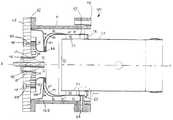
- FIG. 4is a cross section view of the present invention.
- FIG. 5is a detailed cross section view of the end cover of the present invention.
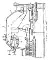
- FIG. 6is a detailed cross section view of a portion of the dome of the present invention.
- FIG. 7is a detailed cross section view of a portion of the aft injector assembly of the present invention.
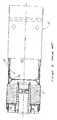
- FIG. 8is a detailed cross section view of the aft injector assembly of the present invention.
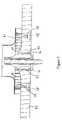
- FIG. 9is a cross section view of an alternate embodiment of the present invention.
- Combustion system 40includes a casing 41 having a first end 42 , a second end 43 , and a center axis A-A.
- Casing 41which is mounted to an engine through flange 44 , is in fluid communication with compressed air from a compressor.
- an end cover 45is fixed to casing first end 42 , with end cover 45 having at least one fuel source in fluid communication with at least one set of injectors.
- a first fuel source 46is in fluid communication with a plurality of first injectors 47 , where first injectors 47 , comprising at least two injectors, are arranged in a first array radially outward of center axis A-A.
- the preferred embodiment of end cover 45also contains a second fuel source 48 in fluid communication with a plurality of second injectors 49 , where second injectors 49 are arranged in a second array radially outward of first injectors 47 .
- second injectors 49comprises at least two injectors.
- a dome 50is located radially inward from casing 41 , thereby forming, a first passage 51 . Also located radially inward from casing 41 is a liner 53 , having a first part 54 located radially inward from dome 50 , thereby forming a second passage 55 between dome 50 and first part 54 of liner 53 . Dome 50 also contains a first opening 56 , an inner dome wall 57 , and an outer dome wall 58 , where inner dome wall 57 and outer dome wall 58 have a third passage 59 therebetween.
- An additional feature of dome 50is the plurality of first feed holes 60 in outer dome wall 58 that extend from third passage 59 to first passage 51 .
- a first swirler 61is positioned adjacent end cover 45 and has a plurality of passageways 62 .
- First swirler 61is oriented such that a first portion of compressed air from the engine compressor passes through the plurality of passageways 62 prior to entering the liner.
- Passageways 62are oriented generally perpendicular to the center axis A-A such that the first portion of compressed air is introduced radially into swirler 61 .
- the combustion system of the present inventionfurther contains an aft injector assembly 63 , which is shown in FIGS. 4, 7, and 8 .
- Aft injector assembly 63contains a manifold 64 having at least one sector.
- manifold 64contains a plurality of sectors 65 , 66 , 67 , and 68 , with each of the sectors in fluid communication with a third fuel source 69 .
- Each of the sectors 65 , 66 , 67 , and 68is isolated from adjacent sectors by a manifold wall 65 ′, 66 ′, 67 ′, and 68 ′ so that fuel supplied to one of the sectors does not flow into another sector of the aft injector assembly 63 .
- Valve meanspermit the fuel flow to each sector to be controlled independent of the other sectors.
- Located in manifold 64is a plurality of third injectors 70 that inject a fuel into second passage 55 .
- Each of the third injectors 70is connected to only one of the sectors 65 , 66 , 67 , or 68 , so that all of the fuel that flows through a particular injector 70 during engine operation is supplied by a single sector 65 , 66 , 67 , or 68 .
- the combustion system of the present inventionutilizes premixing fuel and air prior to combustion in combination with precise staging of fuel flow to the combustor to achieve the reduced emissions at multiple operating load conditions.
- casing 41is in fluid communication with compressed air from a compressor.
- First passage 51 between casing 41 and dome 50receives a first portion of the compressed air.
- the first portion of compressed airthen passes into third passage 59 , which is located between inner dome wall 57 and outer dome wall 58 , by way of a plurality of first feed holes 60 , in order to cool inner dome wall 57 .
- the first portion of compressed airthen flows through a second opening 100 in a dome baffle 102 , and then enters first swirler 61 , passes through passageways 62 , and is directed generally radially inward toward center axis A-A, at which point fuel is introduced to the swirling air through first injectors 47 and second injectors 49 , with second injectors 49 located proximate passageways 62 of first swirler 61 .
- the fuel and air premixture from first injectors 47 , second injectors 49 , and first swirler 61then passes through a fourth passage 71 that directs the premixture through first opening 56 in dome 50 .
- a second portion of compressed air from the compressorpasses through a second swirler 72 , which is located adjacent aft injector assembly 63 , and imparts the second portion of air with a swirl prior to mixing with fuel from aft injector assembly 63 .
- the second portion of compressed air and fuel from aft injector assembly 63mixes in second passage 55 and then, due to the geometry of dome 50 , reverses direction prior to entering combustion zone 73 . Therefore, fluid in first passage 51 and second passage 55 travel in a direction generally opposite to that of combustion products flowing through liner 53 .
- the premixture from fourth passage 71mixes with the premixture from second passage 55 proximate combustion zone 73 .
- some or all of the fuel injectorsmay be in use, with all fuel injectors being used at the highest load condition.
- the fuelis injected at flow rates and at different stages in order to generate the necessary amount of premixing to maintain low emissions throughout the operating spectrum.
- FIG. 9An alternate embodiment of the present invention is shown in cross section in FIG. 9. Included is the addition of sleeve 80 , which is coaxial with center axis A-A and is used for directing the second portion of compressed air to more effectively cool liner 53 , as well as to smooth air flow non-uniformity from the engine compressor.
- Sleeve 80is positioned radially outward of liner 53 and aft of dome 50 such as to form a fifth passage 81 between sleeve 80 and liner 53 that is in fluid communication with second swirler 72 and second passage 55 .
- a plurality of second feed holes 82are placed about sleeve 80 .
Landscapes
- Engineering & Computer Science (AREA)
- Chemical & Material Sciences (AREA)
- Combustion & Propulsion (AREA)
- Mechanical Engineering (AREA)
- General Engineering & Computer Science (AREA)
Abstract
Description
- 1. Field of the Invention[0001]
- This invention relates in general to gas turbine combustion systems and specifically to a gas turbine combustion system that can operate at significantly lower load conditions while having stable combustion and lower emissions.[0002]
- 2. Description of Related Art[0003]
- In an effort to reduce the amount of pollution emissions from gas-powered turbines, governmental agencies have enacted numerous regulations requiring reductions in the amount of oxides of nitrogen (NOx) and carbon monoxide (CO). Lower combustion emissions can often be attributed to a more efficient combustion process, with specific regard to fuel injector location and mixing effectiveness.[0004]
- Early combustion systems utilized diffusion type nozzles, where fuel is mixed with air external to the fuel nozzle by diffusion, proximate the flame zone. Diffusion type nozzles produce high emissions due to the fact that the fuel and air burn stoichiometrically at high temperature to maintain adequate combustor stability and low combustion dynamics.[0005]
- An enhancement in combustion technology is the utilization of premixing, such that the fuel and air mix prior to combustion to form a homogeneous mixture that burns at a lower temperature than a diffusion type flame and produces lower NOx emissions. Premixing can occur either internal to the fuel nozzle or external thereto, as long as it is upstream of the combustion zone. An example of a premixing combustor of the prior art is shown in FIG. 1. A combustor[0006]8 has a plurality of
fuel nozzles 18, each injecting fuel into apremix cavity 19 where fuel mixes with compressed air fromplenum 10 before enteringcombustion chamber 20. Premixing fuel and air together before combustion allows for the fuel and air to form a more homogeneous mixture, which will burn more completely, resulting in lower emissions. However, in this configuration the fuel is injected in relatively the same plane of the combustor, and prevents any possibility of improvement through altering the mixing length. - An alternate means of premixing and lower emissions is through multiple combustion stages, which allows for enhanced premixing as load increases. Referring now to FIG. 2, an example of a prior art multi-stage combustor is shown. A[0007]
combustor 30 has afirst combustion chamber 31 and asecond combustion chamber 32 separated by aventuri 33, which has anarrow throat region 34. While combustion can occur in either first or second combustion chambers or both chambers, depending on load conditions, the lowest emissions levels occur when fuel, which is injected throughnozzle regions 35, is completely mixed with compressed air infirst combustion chamber 31 prior to combusting insecond combustion chamber 32. The amount of load turndown is limited by the decreasing flame temperature as the load is decreased, making the flame unstable to the point where flashback occurs into the first combustion chamber. Therefore, this multi-stage combustor with a venturi is more effective at higher load conditions. While a full load condition is the most common operating point for land-based gas turbines used for generating electricity, often times electricity demands do not require the full load of the generator, and the operator desires to operate the engine at a lower load setting, such that only the load demanded is produced, thereby saving fuel costs. Combustion systems of the prior art have been known to become unstable at lower load settings while also producing unacceptable levels of NOx and CO emissions at lower load settings, especially below 50% load. This is primarily due to the fact that most combustion systems are staged for most efficient operation at high load settings. The combination of potentially unstable combustion and higher emissions often times prevents engine operators from running engines at lower load settings, forcing the engines to either run at higher settings, thereby burning additional fuel, or shutting down, and thereby losing valuable revenue that could be generated from the part-load demand. A further problem with shutting down the engine, is the additional cycles that are incurred by the engine hardware. A cycle is commonly defined as the engine passing through the normal operating envelope. Engine manufacturers typically rate hardware life in terms of operating hours or equivalent operating cycles. Therefore, incurring additional cycles can reduce hardware life requiring premature repair or replacement at the expense of the engine operator. What is needed is a system that can provide flame stability and low emissions benefits at a part load condition, as well as at a full load condition, such that engines can be efficiently operated at lower load conditions, thereby eliminating the wasted fuel when high load operation is not demanded or incurring the additional cycles on the engine hardware when shutting down. - The present invention discloses a gas turbine combustion system for reducing polluting emissions such as NOx and CO, while being able to provide stable combustion at lower load conditions. The combustion system contains a casing having a center axis, which is in fluid communication with the engine compressor, and an end cover fixed to the casing. In the preferred embodiment, the end cover contains a plurality of first injectors arranged in a first array about the end cover and a plurality of second injectors arranged in a second array about the end cover, with the second array radially outward of the first array. Located proximate the end cover is a first swirler having a plurality of passageways oriented generally perpendicular to the casing center axis for inducing a swirl generally radially inward to a first portion of the compressed air. Fuel, which is injected through the first and second injectors, mixes with the first portion of compressed air from the first swirler before entering a liner through a dome section. Additional fuel is also introduced to a second portion of compressed air through a plurality of third injectors located in a manifold of an aft injector assembly. The third injectors are divided into multiple circumferential sectors to allow for various fuel staging circumferentially around the aft injector assembly. To enhance mixing between fuel from the third injectors and second portion of compressed air, a second swirler is positioned adjacent the aft injector assembly for imparting a swirl to the second portion of compressed air. This fuel and air mixes in a second passage located between a first part of the liner and the dome prior to entering the liner and mixing with the fuel and first portion of compressed air from the first swirler region. Upon entering the liner, the premixture from the second passage must undergo a complete reversal of flow direction that causes strong recirculation zones at the forward end of the liner. These recirculation zones help to increase combustor stability by providing a region where a portion of the hot combustion gases can be entrained and recirculate to provide continuous ignition to the incoming premixed fuel and compressed air. Fuel flow to each of the first, second, and third sets of injectors is controlled independently to allow for fuel staging throughout various load conditions to control NOx and CO emissions at each load setting.[0008]
- It is an object of the present invention to provide a combustion system having low NOx and CO at multiple operating conditions.[0009]
- It is a further object of the present invention to provide a combustion system having a stable combustion process throughout all operating conditions.[0010]
- In accordance with these and other objects, which will become apparent hereinafter, the instant invention will now be described with particular reference to the accompanying drawings.[0011]
- FIG. 1 is a cross section view of a portion of a gas turbine engine containing a combustion system of the prior art.[0012]
- FIG. 2 is a cross section view of an alternate combustion system of the prior art.[0013]
- FIG. 3 is a perspective view of the present invention.[0014]
- FIG. 4 is a cross section view of the present invention.[0015]
- FIG. 5 is a detailed cross section view of the end cover of the present invention.[0016]
- FIG. 6 is a detailed cross section view of a portion of the dome of the present invention.[0017]
- FIG. 7 is a detailed cross section view of a portion of the aft injector assembly of the present invention.[0018]
- FIG. 8 is a detailed cross section view of the aft injector assembly of the present invention.[0019]
- FIG. 9 is a cross section view of an alternate embodiment of the present invention.[0020]
- The preferred embodiment of the present invention will now be described in detail with specific reference to FIGS. 3-8. Referring now to FIGS. 3 and 4, a gas[0021]
turbine combustion system 40 of the present invention is shown.Combustion system 40 includes acasing 41 having afirst end 42, asecond end 43, and a center axis A-A.Casing 41, which is mounted to an engine throughflange 44, is in fluid communication with compressed air from a compressor. - Referring now to FIGS. 4 and 5, an[0022]
end cover 45 is fixed to casingfirst end 42, withend cover 45 having at least one fuel source in fluid communication with at least one set of injectors. In the preferred embodiment afirst fuel source 46 is in fluid communication with a plurality offirst injectors 47, wherefirst injectors 47, comprising at least two injectors, are arranged in a first array radially outward of center axis A-A. Furthermore, the preferred embodiment ofend cover 45 also contains asecond fuel source 48 in fluid communication with a plurality ofsecond injectors 49, wheresecond injectors 49 are arranged in a second array radially outward offirst injectors 47. As withfirst injectors 47 it is preferred thatsecond injectors 49 comprises at least two injectors. - Referring now to FIGS. 4 and 6, a[0023]
dome 50 is located radially inward from casing41, thereby forming, afirst passage 51. Also located radially inward from casing41 is aliner 53, having afirst part 54 located radially inward fromdome 50, thereby forming asecond passage 55 betweendome 50 andfirst part 54 ofliner 53.Dome 50 also contains afirst opening 56, aninner dome wall 57, and anouter dome wall 58, whereinner dome wall 57 andouter dome wall 58 have athird passage 59 therebetween. An additional feature ofdome 50 is the plurality of first feed holes60 inouter dome wall 58 that extend fromthird passage 59 tofirst passage 51. - Referring back to FIGS. 4 and 5, a[0024]
first swirler 61 is positionedadjacent end cover 45 and has a plurality ofpassageways 62.First swirler 61 is oriented such that a first portion of compressed air from the engine compressor passes through the plurality ofpassageways 62 prior to entering the liner.Passageways 62 are oriented generally perpendicular to the center axis A-A such that the first portion of compressed air is introduced radially intoswirler 61. - The combustion system of the present invention further contains an[0025]
aft injector assembly 63, which is shown in FIGS. 4, 7, and8.Aft injector assembly 63 contains a manifold64 having at least one sector. In the preferred embodiment of the present invention, manifold64 contains a plurality ofsectors third fuel source 69. Each of thesectors manifold wall 65′,66′,67′, and68′ so that fuel supplied to one of the sectors does not flow into another sector of theaft injector assembly 63. Valve means (not shown) permit the fuel flow to each sector to be controlled independent of the other sectors. Located inmanifold 64 is a plurality ofthird injectors 70 that inject a fuel intosecond passage 55. Each of thethird injectors 70 is connected to only one of thesectors particular injector 70 during engine operation is supplied by asingle sector - The combustion system of the present invention utilizes premixing fuel and air prior to combustion in combination with precise staging of fuel flow to the combustor to achieve the reduced emissions at multiple operating load conditions. In operation, casing[0026]41 is in fluid communication with compressed air from a compressor.
First passage 51 betweencasing 41 anddome 50 receives a first portion of the compressed air. The first portion of compressed air then passes intothird passage 59, which is located betweeninner dome wall 57 andouter dome wall 58, by way of a plurality of first feed holes60, in order to coolinner dome wall 57. The first portion of compressed air then flows through asecond opening 100 in adome baffle 102, and then entersfirst swirler 61, passes throughpassageways 62, and is directed generally radially inward toward center axis A-A, at which point fuel is introduced to the swirling air throughfirst injectors 47 andsecond injectors 49, withsecond injectors 49 locatedproximate passageways 62 offirst swirler 61. The fuel and air premixture fromfirst injectors 47,second injectors 49, andfirst swirler 61 then passes through afourth passage 71 that directs the premixture throughfirst opening 56 indome 50. Meanwhile, a second portion of compressed air from the compressor passes through asecond swirler 72, which is located adjacentaft injector assembly 63, and imparts the second portion of air with a swirl prior to mixing with fuel fromaft injector assembly 63. The second portion of compressed air and fuel fromaft injector assembly 63 mixes insecond passage 55 and then, due to the geometry ofdome 50, reverses direction prior to enteringcombustion zone 73. Therefore, fluid infirst passage 51 andsecond passage 55 travel in a direction generally opposite to that of combustion products flowing throughliner 53. The premixture fromfourth passage 71 mixes with the premixture fromsecond passage 55proximate combustion zone 73. Depending on the load condition, some or all of the fuel injectors may be in use, with all fuel injectors being used at the highest load condition. The fuel is injected at flow rates and at different stages in order to generate the necessary amount of premixing to maintain low emissions throughout the operating spectrum. - An alternate embodiment of the present invention is shown in cross section in FIG. 9. Included is the addition of sleeve[0027]80, which is coaxial with center axis A-A and is used for directing the second portion of compressed air to more effectively
cool liner 53, as well as to smooth air flow non-uniformity from the engine compressor. Sleeve80 is positioned radially outward ofliner 53 and aft ofdome 50 such as to form a fifth passage81 between sleeve80 andliner 53 that is in fluid communication withsecond swirler 72 andsecond passage 55. In order to supply compressed air to fifth passage81 to more effectivelycool liner 53, a plurality of second feed holes82 are placed about sleeve80. Due to pressure changes across second feed holes82, a jet of air is created that impinges on the outside ofliner 53 to cool the surface prior to the compressed air being directed throughsecond swirler 72 and mixing with fuel fromaft injector assembly 63. It should be noted that all other elements of the alternate embodiment of the present invention are the same as the preferred embodiment, and therefore do not require further discussion. - While the invention has been described in what is known as presently the preferred embodiment, it is to be understood that the invention is not to be limited to the disclosed embodiment but, on the contrary, is intended to cover various modifications and equivalent arrangements within the scope of the following claims.[0028]
Claims (22)
Priority Applications (1)
| Application Number | Priority Date | Filing Date | Title |
|---|---|---|---|
| US10/424,350US6935116B2 (en) | 2003-04-28 | 2003-04-28 | Flamesheet combustor |
Applications Claiming Priority (1)
| Application Number | Priority Date | Filing Date | Title |
|---|---|---|---|
| US10/424,350US6935116B2 (en) | 2003-04-28 | 2003-04-28 | Flamesheet combustor |
Publications (2)
| Publication Number | Publication Date |
|---|---|
| US20040211186A1true US20040211186A1 (en) | 2004-10-28 |
| US6935116B2 US6935116B2 (en) | 2005-08-30 |
Family
ID=33299336
Family Applications (1)
| Application Number | Title | Priority Date | Filing Date |
|---|---|---|---|
| US10/424,350Expired - LifetimeUS6935116B2 (en) | 2003-04-28 | 2003-04-28 | Flamesheet combustor |
Country Status (1)
| Country | Link |
|---|---|
| US (1) | US6935116B2 (en) |
Cited By (22)
| Publication number | Priority date | Publication date | Assignee | Title |
|---|---|---|---|---|
| US7137256B1 (en) | 2005-02-28 | 2006-11-21 | Peter Stuttaford | Method of operating a combustion system for increased turndown capability |
| EP1890083A1 (en)* | 2006-08-16 | 2008-02-20 | Siemens Aktiengesellschaft | Fuel injector for a gas turbine engine |
| EP2169312A1 (en)* | 2008-09-25 | 2010-03-31 | Siemens Aktiengesellschaft | Stepped swirler for dynamic control |
| US20130025289A1 (en)* | 2011-07-29 | 2013-01-31 | General Electric Company | Combustor portion for a turbomachine and method of operating a turbomachine |
| CN103123121A (en)* | 2011-11-18 | 2013-05-29 | 通用电气公司 | Gas turbine combustor endcover with adjustable flow restrictor and related method |
| CN103307634A (en)* | 2012-03-12 | 2013-09-18 | 通用电气公司 | Combustor and method of reducing thermal stresses in the combustor |
| WO2014029512A2 (en) | 2012-08-24 | 2014-02-27 | Alstom Technology Ltd | Sequential combustion with dilution gas mixer |
| US8863525B2 (en) | 2011-01-03 | 2014-10-21 | General Electric Company | Combustor with fuel staggering for flame holding mitigation |
| EP2837888A1 (en) | 2013-08-15 | 2015-02-18 | Alstom Technology Ltd | Sequential combustion with dilution gas mixer |
| US8991187B2 (en) | 2010-10-11 | 2015-03-31 | General Electric Company | Combustor with a lean pre-nozzle fuel injection system |
| US20150089954A1 (en)* | 2012-08-17 | 2015-04-02 | Dürr Systems GmbH | Burners having fuel plenums |
| EP2857658A1 (en) | 2013-10-01 | 2015-04-08 | Alstom Technology Ltd | Gas turbine with sequential combustion arrangement |
| US20150184858A1 (en)* | 2012-10-01 | 2015-07-02 | Peter John Stuttford | Method of operating a multi-stage flamesheet combustor |
| EP2921779A1 (en) | 2014-03-18 | 2015-09-23 | Alstom Technology Ltd | Combustion chamber with cooling sleeve |
| US20160084169A1 (en)* | 2012-10-01 | 2016-03-24 | Peter John Stuttaford | Method of operating a multi-stage flamesheet combustor |
| US20160146467A1 (en)* | 2014-11-25 | 2016-05-26 | General Electric Technology Gmbh | Combustor liner |
| EP3026347A1 (en) | 2014-11-25 | 2016-06-01 | Alstom Technology Ltd | Combustor with annular bluff body |
| EP3067622A1 (en) | 2015-03-12 | 2016-09-14 | General Electric Technology GmbH | Combustion chamber with double wall |
| EP3135880A1 (en) | 2015-08-25 | 2017-03-01 | General Electric Technology GmbH | Gas turbine with a sequential combustion arrangement and fuel composition control |
| EP3499128A1 (en)* | 2017-12-15 | 2019-06-19 | Delavan, Inc. | Fuel injector systems and support structures |
| US11143407B2 (en) | 2013-06-11 | 2021-10-12 | Raytheon Technologies Corporation | Combustor with axial staging for a gas turbine engine |
| US20220341595A1 (en)* | 2021-03-26 | 2022-10-27 | Honda Motor Co., Ltd. | Fuel nozzle device for gas turbine engine |
Families Citing this family (40)
| Publication number | Priority date | Publication date | Assignee | Title |
|---|---|---|---|---|
| US7665308B2 (en)* | 2005-11-07 | 2010-02-23 | General Electric Company | Methods and apparatus for injecting fluids into a turbine engine |
| US7451602B2 (en)* | 2005-11-07 | 2008-11-18 | General Electric Company | Methods and apparatus for injecting fluids into turbine engines |
| US7878002B2 (en)* | 2007-04-17 | 2011-02-01 | General Electric Company | Methods and systems to facilitate reducing combustor pressure drops |
| US8096133B2 (en)* | 2008-05-13 | 2012-01-17 | General Electric Company | Method and apparatus for cooling and dilution tuning a gas turbine combustor liner and transition piece interface |
| US8215116B2 (en)* | 2008-10-02 | 2012-07-10 | General Electric Company | System and method for air-fuel mixing in gas turbines |
| US7712314B1 (en) | 2009-01-21 | 2010-05-11 | Gas Turbine Efficiency Sweden Ab | Venturi cooling system |
| US8281596B1 (en)* | 2011-05-16 | 2012-10-09 | General Electric Company | Combustor assembly for a turbomachine |
| WO2013002669A1 (en) | 2011-06-30 | 2013-01-03 | General Electric Company | Combustor and method of supplying fuel to the combustor |
| EP2726786B1 (en) | 2011-06-30 | 2018-04-04 | General Electric Company | Combustor and method of supplying fuel to the combustor |
| US9243804B2 (en) | 2011-10-24 | 2016-01-26 | General Electric Company | System for turbine combustor fuel mixing |
| US9188061B2 (en) | 2011-10-24 | 2015-11-17 | General Electric Company | System for turbine combustor fuel assembly |
| US8973366B2 (en) | 2011-10-24 | 2015-03-10 | General Electric Company | Integrated fuel and water mixing assembly for use in conjunction with a combustor |
| US9267433B2 (en) | 2011-10-24 | 2016-02-23 | General Electric Company | System and method for turbine combustor fuel assembly |
| US9267687B2 (en) | 2011-11-04 | 2016-02-23 | General Electric Company | Combustion system having a venturi for reducing wakes in an airflow |
| US8899975B2 (en) | 2011-11-04 | 2014-12-02 | General Electric Company | Combustor having wake air injection |
| US9170024B2 (en) | 2012-01-06 | 2015-10-27 | General Electric Company | System and method for supplying a working fluid to a combustor |
| US9188337B2 (en) | 2012-01-13 | 2015-11-17 | General Electric Company | System and method for supplying a working fluid to a combustor via a non-uniform distribution manifold |
| US9097424B2 (en) | 2012-03-12 | 2015-08-04 | General Electric Company | System for supplying a fuel and working fluid mixture to a combustor |
| US9151500B2 (en) | 2012-03-15 | 2015-10-06 | General Electric Company | System for supplying a fuel and a working fluid through a liner to a combustion chamber |
| US9284888B2 (en) | 2012-04-25 | 2016-03-15 | General Electric Company | System for supplying fuel to late-lean fuel injectors of a combustor |
| US9052115B2 (en) | 2012-04-25 | 2015-06-09 | General Electric Company | System and method for supplying a working fluid to a combustor |
| US8677753B2 (en) | 2012-05-08 | 2014-03-25 | General Electric Company | System for supplying a working fluid to a combustor |
| RU2561956C2 (en) | 2012-07-09 | 2015-09-10 | Альстом Текнолоджи Лтд | Gas-turbine combustion system |
| US9212823B2 (en) | 2012-09-06 | 2015-12-15 | General Electric Company | Systems and methods for suppressing combustion driven pressure fluctuations with a premix combustor having multiple premix times |
| US9752781B2 (en) | 2012-10-01 | 2017-09-05 | Ansaldo Energia Ip Uk Limited | Flamesheet combustor dome |
| US9897317B2 (en) | 2012-10-01 | 2018-02-20 | Ansaldo Energia Ip Uk Limited | Thermally free liner retention mechanism |
| US9631815B2 (en)* | 2012-12-28 | 2017-04-25 | General Electric Company | System and method for a turbine combustor |
| US9739201B2 (en) | 2013-05-08 | 2017-08-22 | General Electric Company | Wake reducing structure for a turbine system and method of reducing wake |
| US9322553B2 (en) | 2013-05-08 | 2016-04-26 | General Electric Company | Wake manipulating structure for a turbine system |
| US9435221B2 (en) | 2013-08-09 | 2016-09-06 | General Electric Company | Turbomachine airfoil positioning |
| EP2894405B1 (en) | 2014-01-10 | 2016-11-23 | General Electric Technology GmbH | Sequential combustion arrangement with dilution gas |
| CN107923618B (en) | 2015-06-30 | 2021-02-26 | 安萨尔多能源英国知识产权有限公司 | Gas turbine fuel component |
| US10571128B2 (en) | 2015-06-30 | 2020-02-25 | Ansaldo Energia Ip Uk Limited | Gas turbine fuel components |
| WO2017002076A1 (en) | 2015-06-30 | 2017-01-05 | Ansaldo Energia Ip Uk Limited | Gas turbine control system |
| EP3130848B1 (en) | 2015-08-12 | 2019-01-16 | Ansaldo Energia Switzerland AG | Sequential combustion arrangement with cooling gas for dilution |
| EP3133343A1 (en) | 2015-08-18 | 2017-02-22 | General Electric Technology GmbH | Gas turbine with diluted liquid fuel |
| US20170299189A1 (en)* | 2016-04-18 | 2017-10-19 | Dresser-Rand Company | Single can vortex combustor |
| US10527286B2 (en) | 2016-12-16 | 2020-01-07 | Delavan, Inc | Staged radial air swirler with radial liquid fuel distributor |
| US10954859B2 (en) | 2017-07-25 | 2021-03-23 | Raytheon Technologies Corporation | Low emissions combustor assembly for gas turbine engine |
| US11371709B2 (en) | 2020-06-30 | 2022-06-28 | General Electric Company | Combustor air flow path |
Citations (24)
| Publication number | Priority date | Publication date | Assignee | Title |
|---|---|---|---|---|
| US2446059A (en)* | 1944-10-05 | 1948-07-27 | Peabody Engineering Corp | Gas heater |
| US2621477A (en)* | 1948-06-03 | 1952-12-16 | Power Jets Res & Dev Ltd | Combustion apparatus having valve controlled passages for preheating the fuel-air mixture |
| US3121996A (en)* | 1961-10-02 | 1964-02-25 | Lucas Industries Ltd | Liquid fuel combustion apparatus |
| US3169367A (en)* | 1963-07-18 | 1965-02-16 | Westinghouse Electric Corp | Combustion apparatus |
| US4050238A (en)* | 1975-03-14 | 1977-09-27 | Daimler-Benz Aktiengesellschaft | Film evaporating combustion chamber |
| US4112676A (en)* | 1977-04-05 | 1978-09-12 | Westinghouse Electric Corp. | Hybrid combustor with staged injection of pre-mixed fuel |
| US4735052A (en)* | 1985-09-30 | 1988-04-05 | Kabushiki Kaisha Toshiba | Gas turbine apparatus |
| US5121597A (en)* | 1989-02-03 | 1992-06-16 | Hitachi, Ltd. | Gas turbine combustor and methodd of operating the same |
| US5231833A (en)* | 1991-01-18 | 1993-08-03 | General Electric Company | Gas turbine engine fuel manifold |
| US5319935A (en)* | 1990-10-23 | 1994-06-14 | Rolls-Royce Plc | Staged gas turbine combustion chamber with counter swirling arrays of radial vanes having interjacent fuel injection |
| US5321949A (en)* | 1991-07-12 | 1994-06-21 | General Electric Company | Staged fuel delivery system with secondary distribution valve |
| US5640851A (en)* | 1993-05-24 | 1997-06-24 | Rolls-Royce Plc | Gas turbine engine combustion chamber |
| US5647215A (en)* | 1995-11-07 | 1997-07-15 | Westinghouse Electric Corporation | Gas turbine combustor with turbulence enhanced mixing fuel injectors |
| US5761906A (en)* | 1995-01-13 | 1998-06-09 | European Gas Turbines Limited | Fuel injector swirler arrangement having a shield means for creating fuel rich pockets in gas-or liquid-fuelled turbine |
| US5765376A (en)* | 1994-12-16 | 1998-06-16 | Mtu Motoren- Und Turbinen-Union Muenchen Gmbh | Gas turbine engine flame tube cooling system and integral swirler arrangement |
| US5983642A (en)* | 1997-10-13 | 1999-11-16 | Siemens Westinghouse Power Corporation | Combustor with two stage primary fuel tube with concentric members and flow regulating |
| US6151899A (en)* | 1998-05-09 | 2000-11-28 | Alstom Gas Turbines Limited | Gas-turbine engine combustor |
| US6209325B1 (en)* | 1996-03-29 | 2001-04-03 | European Gas Turbines Limited | Combustor for gas- or liquid-fueled turbine |
| US6253555B1 (en)* | 1998-08-21 | 2001-07-03 | Rolls-Royce Plc | Combustion chamber comprising mixing ducts with fuel injectors varying in number and cross-sectional area |
| US6345505B1 (en)* | 1998-10-30 | 2002-02-12 | United Technologies Corporation | Dual fuel mixing in a multishear fuel injector with a plurality of concentric ducts |
| US20020020173A1 (en)* | 2000-08-10 | 2002-02-21 | Varney Brian A. | Combustion chamber |
| US6374615B1 (en)* | 2000-01-28 | 2002-04-23 | Alliedsignal, Inc | Low cost, low emissions natural gas combustor |
| US6532726B2 (en)* | 1998-01-31 | 2003-03-18 | Alstom Gas Turbines, Ltd. | Gas-turbine engine combustion system |
| US6609376B2 (en)* | 2000-02-14 | 2003-08-26 | Ulstein Turbine As | Device in a burner for gas turbines |
- 2003
- 2003-04-28USUS10/424,350patent/US6935116B2/ennot_activeExpired - Lifetime
Patent Citations (25)
| Publication number | Priority date | Publication date | Assignee | Title |
|---|---|---|---|---|
| US2446059A (en)* | 1944-10-05 | 1948-07-27 | Peabody Engineering Corp | Gas heater |
| US2621477A (en)* | 1948-06-03 | 1952-12-16 | Power Jets Res & Dev Ltd | Combustion apparatus having valve controlled passages for preheating the fuel-air mixture |
| US3121996A (en)* | 1961-10-02 | 1964-02-25 | Lucas Industries Ltd | Liquid fuel combustion apparatus |
| US3169367A (en)* | 1963-07-18 | 1965-02-16 | Westinghouse Electric Corp | Combustion apparatus |
| US4050238A (en)* | 1975-03-14 | 1977-09-27 | Daimler-Benz Aktiengesellschaft | Film evaporating combustion chamber |
| US4112676A (en)* | 1977-04-05 | 1978-09-12 | Westinghouse Electric Corp. | Hybrid combustor with staged injection of pre-mixed fuel |
| US4735052A (en)* | 1985-09-30 | 1988-04-05 | Kabushiki Kaisha Toshiba | Gas turbine apparatus |
| US5121597A (en)* | 1989-02-03 | 1992-06-16 | Hitachi, Ltd. | Gas turbine combustor and methodd of operating the same |
| US5319935A (en)* | 1990-10-23 | 1994-06-14 | Rolls-Royce Plc | Staged gas turbine combustion chamber with counter swirling arrays of radial vanes having interjacent fuel injection |
| US5231833A (en)* | 1991-01-18 | 1993-08-03 | General Electric Company | Gas turbine engine fuel manifold |
| US5321949A (en)* | 1991-07-12 | 1994-06-21 | General Electric Company | Staged fuel delivery system with secondary distribution valve |
| US5640851A (en)* | 1993-05-24 | 1997-06-24 | Rolls-Royce Plc | Gas turbine engine combustion chamber |
| US5765376A (en)* | 1994-12-16 | 1998-06-16 | Mtu Motoren- Und Turbinen-Union Muenchen Gmbh | Gas turbine engine flame tube cooling system and integral swirler arrangement |
| US5761906A (en)* | 1995-01-13 | 1998-06-09 | European Gas Turbines Limited | Fuel injector swirler arrangement having a shield means for creating fuel rich pockets in gas-or liquid-fuelled turbine |
| US5647215A (en)* | 1995-11-07 | 1997-07-15 | Westinghouse Electric Corporation | Gas turbine combustor with turbulence enhanced mixing fuel injectors |
| US6209325B1 (en)* | 1996-03-29 | 2001-04-03 | European Gas Turbines Limited | Combustor for gas- or liquid-fueled turbine |
| US5983642A (en)* | 1997-10-13 | 1999-11-16 | Siemens Westinghouse Power Corporation | Combustor with two stage primary fuel tube with concentric members and flow regulating |
| US6532726B2 (en)* | 1998-01-31 | 2003-03-18 | Alstom Gas Turbines, Ltd. | Gas-turbine engine combustion system |
| US6151899A (en)* | 1998-05-09 | 2000-11-28 | Alstom Gas Turbines Limited | Gas-turbine engine combustor |
| US6253555B1 (en)* | 1998-08-21 | 2001-07-03 | Rolls-Royce Plc | Combustion chamber comprising mixing ducts with fuel injectors varying in number and cross-sectional area |
| US6345505B1 (en)* | 1998-10-30 | 2002-02-12 | United Technologies Corporation | Dual fuel mixing in a multishear fuel injector with a plurality of concentric ducts |
| US6374615B1 (en)* | 2000-01-28 | 2002-04-23 | Alliedsignal, Inc | Low cost, low emissions natural gas combustor |
| US6609376B2 (en)* | 2000-02-14 | 2003-08-26 | Ulstein Turbine As | Device in a burner for gas turbines |
| US20020020173A1 (en)* | 2000-08-10 | 2002-02-21 | Varney Brian A. | Combustion chamber |
| US6513334B2 (en)* | 2000-08-10 | 2003-02-04 | Rolls-Royce Plc | Combustion chamber |
Cited By (40)
| Publication number | Priority date | Publication date | Assignee | Title |
|---|---|---|---|---|
| US7137256B1 (en) | 2005-02-28 | 2006-11-21 | Peter Stuttaford | Method of operating a combustion system for increased turndown capability |
| EP1890083A1 (en)* | 2006-08-16 | 2008-02-20 | Siemens Aktiengesellschaft | Fuel injector for a gas turbine engine |
| US20080041060A1 (en)* | 2006-08-16 | 2008-02-21 | Siemens Aktiengesellschaft | Fuel injector for a gas turbine engine |
| US8678301B2 (en) | 2008-09-25 | 2014-03-25 | Siemens Aktiengesellschaft | Stepped swirler for dynamic control |
| EP2169312A1 (en)* | 2008-09-25 | 2010-03-31 | Siemens Aktiengesellschaft | Stepped swirler for dynamic control |
| WO2010034558A1 (en)* | 2008-09-25 | 2010-04-01 | Siemens Aktiengesellschaft | Stepped swirler for dynamic control |
| US20110168801A1 (en)* | 2008-09-25 | 2011-07-14 | Phillip Hubbard | Stepped swirler for dynamic control |
| US8991187B2 (en) | 2010-10-11 | 2015-03-31 | General Electric Company | Combustor with a lean pre-nozzle fuel injection system |
| US9416974B2 (en) | 2011-01-03 | 2016-08-16 | General Electric Company | Combustor with fuel staggering for flame holding mitigation |
| US8863525B2 (en) | 2011-01-03 | 2014-10-21 | General Electric Company | Combustor with fuel staggering for flame holding mitigation |
| US9297534B2 (en)* | 2011-07-29 | 2016-03-29 | General Electric Company | Combustor portion for a turbomachine and method of operating a turbomachine |
| US20130025289A1 (en)* | 2011-07-29 | 2013-01-31 | General Electric Company | Combustor portion for a turbomachine and method of operating a turbomachine |
| EP2551598A3 (en)* | 2011-07-29 | 2017-11-08 | General Electric Company | Combustor portion for a turbomachine and method of operatig a turbomachine |
| CN103123121A (en)* | 2011-11-18 | 2013-05-29 | 通用电气公司 | Gas turbine combustor endcover with adjustable flow restrictor and related method |
| CN103307634A (en)* | 2012-03-12 | 2013-09-18 | 通用电气公司 | Combustor and method of reducing thermal stresses in the combustor |
| US20150089954A1 (en)* | 2012-08-17 | 2015-04-02 | Dürr Systems GmbH | Burners having fuel plenums |
| US9982891B2 (en)* | 2012-08-17 | 2018-05-29 | Dürr Systems Ag | Burners having fuel plenums |
| WO2014029512A2 (en) | 2012-08-24 | 2014-02-27 | Alstom Technology Ltd | Sequential combustion with dilution gas mixer |
| US9890955B2 (en) | 2012-08-24 | 2018-02-13 | Ansaldo Energia Switzerland AG | Sequential combustion with dilution gas mixer |
| US10634357B2 (en) | 2012-08-24 | 2020-04-28 | Ansaldo Energia Switzerland AG | Sequential combustion with dilution gas mixer |
| US20160084169A1 (en)* | 2012-10-01 | 2016-03-24 | Peter John Stuttaford | Method of operating a multi-stage flamesheet combustor |
| US20150184858A1 (en)* | 2012-10-01 | 2015-07-02 | Peter John Stuttford | Method of operating a multi-stage flamesheet combustor |
| US10378456B2 (en)* | 2012-10-01 | 2019-08-13 | Ansaldo Energia Switzerland AG | Method of operating a multi-stage flamesheet combustor |
| US11143407B2 (en) | 2013-06-11 | 2021-10-12 | Raytheon Technologies Corporation | Combustor with axial staging for a gas turbine engine |
| US9885481B2 (en) | 2013-08-15 | 2018-02-06 | Ansaldo Energia Switzerland AG | Sequential combustion with dilution gas mixer |
| EP2837889A1 (en) | 2013-08-15 | 2015-02-18 | Alstom Technology Ltd | Sequential combustion with dilution gas mixer |
| EP2837888A1 (en) | 2013-08-15 | 2015-02-18 | Alstom Technology Ltd | Sequential combustion with dilution gas mixer |
| EP2857658A1 (en) | 2013-10-01 | 2015-04-08 | Alstom Technology Ltd | Gas turbine with sequential combustion arrangement |
| US9708983B2 (en) | 2013-10-01 | 2017-07-18 | Ansaldo Energia Switzerland AG | Gas turbine with sequential combustion arrangement |
| EP2921779A1 (en) | 2014-03-18 | 2015-09-23 | Alstom Technology Ltd | Combustion chamber with cooling sleeve |
| EP3026346A1 (en) | 2014-11-25 | 2016-06-01 | Alstom Technology Ltd | Combustor liner |
| EP3026347A1 (en) | 2014-11-25 | 2016-06-01 | Alstom Technology Ltd | Combustor with annular bluff body |
| US20160146467A1 (en)* | 2014-11-25 | 2016-05-26 | General Electric Technology Gmbh | Combustor liner |
| EP3067622A1 (en) | 2015-03-12 | 2016-09-14 | General Electric Technology GmbH | Combustion chamber with double wall |
| EP3135880A1 (en) | 2015-08-25 | 2017-03-01 | General Electric Technology GmbH | Gas turbine with a sequential combustion arrangement and fuel composition control |
| EP3499128A1 (en)* | 2017-12-15 | 2019-06-19 | Delavan, Inc. | Fuel injector systems and support structures |
| US11002193B2 (en) | 2017-12-15 | 2021-05-11 | Delavan Inc. | Fuel injector systems and support structures |
| US11852075B2 (en) | 2017-12-15 | 2023-12-26 | Collins Engine Nozzles, Inc. | Fuel injector systems and support structures |
| US20220341595A1 (en)* | 2021-03-26 | 2022-10-27 | Honda Motor Co., Ltd. | Fuel nozzle device for gas turbine engine |
| US11725821B2 (en)* | 2021-03-26 | 2023-08-15 | Honda Motor Co., Ltd. | Fuel nozzle device for gas turbine engine |
Also Published As
| Publication number | Publication date |
|---|---|
| US6935116B2 (en) | 2005-08-30 |
Similar Documents
| Publication | Publication Date | Title |
|---|---|---|
| US6935116B2 (en) | Flamesheet combustor | |
| JP4658471B2 (en) | Method and apparatus for reducing combustor emissions in a gas turbine engine | |
| US5836164A (en) | Gas turbine combustor | |
| US4271674A (en) | Premix combustor assembly | |
| US5408830A (en) | Multi-stage fuel nozzle for reducing combustion instabilities in low NOX gas turbines | |
| JP4733284B2 (en) | Method and apparatus for reducing gas turbine engine exhaust | |
| US8763359B2 (en) | Apparatus for combusting fuel within a gas turbine engine | |
| US6986254B2 (en) | Method of operating a flamesheet combustor | |
| KR0149059B1 (en) | Gas turbine burner | |
| US7685823B2 (en) | Airflow distribution to a low emissions combustor | |
| US20140090396A1 (en) | Combustor with radially staged premixed pilot for improved | |
| US20040006989A1 (en) | Fully premixed secondary fuel nozzle with dual fuel capability | |
| US20040006991A1 (en) | Fully premixed secondary fuel nozzle with improved stability and dual fuel capability | |
| US20040006993A1 (en) | Dual fuel fin mixer secondary fuel nozzle | |
| US20090320484A1 (en) | Methods and systems to facilitate reducing flashback/flame holding in combustion systems | |
| CA2135974A1 (en) | Gas turbine engine combustion chamber | |
| US7024861B2 (en) | Fully premixed pilotless secondary fuel nozzle with improved tip cooling | |
| US7677025B2 (en) | Self-purging pilot fuel injection system | |
| JP2006170605A (en) | Gas turbine engine and fuel supply device | |
| US6327860B1 (en) | Fuel injector for low emissions premixing gas turbine combustor | |
| US6813890B2 (en) | Fully premixed pilotless secondary fuel nozzle | |
| GB2073399A (en) | Dual premix tube fuel nozzle | |
| EP1243854B1 (en) | Fuel injector | |
| EP1994334B1 (en) | Combustor and method of operating a combustor |
Legal Events
| Date | Code | Title | Description |
|---|---|---|---|
| AS | Assignment | Owner name:POWER SYSTEMS MFG, LLC., FLORIDA Free format text:ASSIGNMENT OF ASSIGNORS INTEREST;ASSIGNORS:STUTTAFORD, PETER J.;JENNINGS, STEPHEN;GREEN, ANDREW;AND OTHERS;REEL/FRAME:014014/0485;SIGNING DATES FROM 20030422 TO 20030428 | |
| STCF | Information on status: patent grant | Free format text:PATENTED CASE | |
| FPAY | Fee payment | Year of fee payment:4 | |
| AS | Assignment | Owner name:ALSTOM TECHNOLOGY LTD, SWITZERLAND Free format text:ASSIGNMENT OF ASSIGNORS INTEREST;ASSIGNOR:POWER SYSTEMS MFG., LLC;REEL/FRAME:028801/0141 Effective date:20070401 | |
| FPAY | Fee payment | Year of fee payment:8 | |
| AS | Assignment | Owner name:GENERAL ELECTRIC TECHNOLOGY GMBH, SWITZERLAND Free format text:CHANGE OF NAME;ASSIGNOR:ALSTOM TECHNOLOGY LTD;REEL/FRAME:039300/0039 Effective date:20151102 | |
| AS | Assignment | Owner name:ANSALDO ENERGIA IP UK LIMITED, GREAT BRITAIN Free format text:ASSIGNMENT OF ASSIGNORS INTEREST;ASSIGNOR:GENERAL ELECTRIC TECHNOLOGY GMBH;REEL/FRAME:041731/0626 Effective date:20170109 | |
| FPAY | Fee payment | Year of fee payment:12 | |
| AS | Assignment | Owner name:H2 IP UK LIMITED, UNITED KINGDOM Free format text:ASSIGNMENT OF ASSIGNORS INTEREST;ASSIGNOR:ANSALDO ENERGIA IP UK LIMITED;REEL/FRAME:056446/0270 Effective date:20210527 |