US20040178958A1 - Antenna with shorted active and passive planar loops and method of making the same - Google Patents
Antenna with shorted active and passive planar loops and method of making the sameDownload PDFInfo
- Publication number
- US20040178958A1 US20040178958A1US10/622,890US62289003AUS2004178958A1US 20040178958 A1US20040178958 A1US 20040178958A1US 62289003 AUS62289003 AUS 62289003AUS 2004178958 A1US2004178958 A1US 2004178958A1
- Authority
- US
- United States
- Prior art keywords
- antenna according
- radiating
- radiating element
- conductive strip
- shorting
- Prior art date
- Legal status (The legal status is an assumption and is not a legal conclusion. Google has not performed a legal analysis and makes no representation as to the accuracy of the status listed.)
- Granted
Links
Images


Classifications
- H—ELECTRICITY
- H01—ELECTRIC ELEMENTS
- H01Q—ANTENNAS, i.e. RADIO AERIALS
- H01Q9/00—Electrically-short antennas having dimensions not more than twice the operating wavelength and consisting of conductive active radiating elements
- H01Q9/04—Resonant antennas
- H01Q9/0407—Substantially flat resonant element parallel to ground plane, e.g. patch antenna
- H—ELECTRICITY
- H01—ELECTRIC ELEMENTS
- H01Q—ANTENNAS, i.e. RADIO AERIALS
- H01Q1/00—Details of, or arrangements associated with, antennas
- H01Q1/12—Supports; Mounting means
- H01Q1/22—Supports; Mounting means by structural association with other equipment or articles
- H01Q1/24—Supports; Mounting means by structural association with other equipment or articles with receiving set
- H01Q1/241—Supports; Mounting means by structural association with other equipment or articles with receiving set used in mobile communications, e.g. GSM
- H01Q1/242—Supports; Mounting means by structural association with other equipment or articles with receiving set used in mobile communications, e.g. GSM specially adapted for hand-held use
- H01Q1/243—Supports; Mounting means by structural association with other equipment or articles with receiving set used in mobile communications, e.g. GSM specially adapted for hand-held use with built-in antennas
- H—ELECTRICITY
- H01—ELECTRIC ELEMENTS
- H01Q—ANTENNAS, i.e. RADIO AERIALS
- H01Q1/00—Details of, or arrangements associated with, antennas
- H01Q1/36—Structural form of radiating elements, e.g. cone, spiral, umbrella; Particular materials used therewith
- H01Q1/38—Structural form of radiating elements, e.g. cone, spiral, umbrella; Particular materials used therewith formed by a conductive layer on an insulating support
- H—ELECTRICITY
- H01—ELECTRIC ELEMENTS
- H01Q—ANTENNAS, i.e. RADIO AERIALS
- H01Q13/00—Waveguide horns or mouths; Slot antennas; Leaky-waveguide antennas; Equivalent structures causing radiation along the transmission path of a guided wave
- H01Q13/20—Non-resonant leaky-waveguide or transmission-line antennas; Equivalent structures causing radiation along the transmission path of a guided wave
- H01Q13/206—Microstrip transmission line antennas
- H—ELECTRICITY
- H01—ELECTRIC ELEMENTS
- H01Q—ANTENNAS, i.e. RADIO AERIALS
- H01Q7/00—Loop antennas with a substantially uniform current distribution around the loop and having a directional radiation pattern in a plane perpendicular to the plane of the loop
- H—ELECTRICITY
- H01—ELECTRIC ELEMENTS
- H01Q—ANTENNAS, i.e. RADIO AERIALS
- H01Q9/00—Electrically-short antennas having dimensions not more than twice the operating wavelength and consisting of conductive active radiating elements
- H01Q9/04—Resonant antennas
- H01Q9/0407—Substantially flat resonant element parallel to ground plane, e.g. patch antenna
- H01Q9/0421—Substantially flat resonant element parallel to ground plane, e.g. patch antenna with a shorting wall or a shorting pin at one end of the element
- H—ELECTRICITY
- H01—ELECTRIC ELEMENTS
- H01Q—ANTENNAS, i.e. RADIO AERIALS
- H01Q9/00—Electrically-short antennas having dimensions not more than twice the operating wavelength and consisting of conductive active radiating elements
- H01Q9/04—Resonant antennas
- H01Q9/30—Resonant antennas with feed to end of elongated active element, e.g. unipole
- H01Q9/42—Resonant antennas with feed to end of elongated active element, e.g. unipole with folded element, the folded parts being spaced apart a small fraction of the operating wavelength
Definitions
- the present inventionis related to U.S. patent application Ser. No. 10/314,791, filed Dec. 12, 2002, titled C OMPACT L OW P ROFILE S INGLE F EED M ULTI B AND P RINTED A NTENNAS , Kadambi et al., U.S. patent application Ser. No. 10/135,312, filed Apr. 29, 2002 titled S INGLE F EED T RI B AND PIFA WITH P ARASITIC E LEMENT , Kadambi et al., and U.S. Provisional Patent Application serial No. 60/424,850, filed Nov. 8, 2002, titled O PTIMUM U TILIZATION OF S LOT G AP IN PIFA D ESIGN , Kadambi et al.
- the present inventionrelates to antenna and, more particularly, to antenna having shorted planar loops.
- the Planar Inverted F-Antennahas proven to be a versatile choice as an internal antenna for the multi band and multi system antenna.
- the PIFArequires a relatively large volume of space in present compact wireless devices.
- the volume or amount of space the PIFA occupiescontinues to be a significant determining factor for its desirable performance.
- an antenna with shorted active and passive planar loopsin provided.
- the antennais comprised of a conductive trace forming a first radiating element residing over a ground plane.
- the radiating elementforms a loop antenna having a gap.
- the loop antennahas a radiating edge opposite a non radiating edge.
- a shorting element and feed tabare located on the non radiating edge.
- Multi band operating of the antennais achieved by placing a second radiating element where at least a portion of the second radiating element is internal to a geometry formed by the first radiating element.
- FIG. 1is a plan view of an embodiment of an antenna consistent with the present invention
- FIG. 1Ais an elevation view of the antenna of FIG. 1;
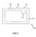
- FIG. 2is a plan view of another embodiment of an antenna consistent with the present invention.
- FIG. 3Ais a plan view of another embodiment of an antenna consistent with the present invention.
- FIG. 3Bis a plan view of another embodiment of an antenna consistent with the present invention.
- FIG. 4is a plan view of another embodiment of an antenna consistent with the present invention.
- FIG. 5is a plan view of another embodiment of an antenna consistent with the present invention.
- FIGS. 1-5 and the following paragraphsdescribe some embodiments of the present invention.
- Like reference charactersare used wherever possible to identify like components or blocks to simplify the description of the various subcomponents described herein. More particularly, the present invention is described in relation to particular embodiments thereof; however, one of ordinary skill in the art will understand on reading the following disclosure that other configurations are possible without departing from the spirit and scope of the present invention.
- PIFAPIFA
- the slotforms a quasi partitioning of the radiating element allowing the PIFA to operate in multiple frequency bands.
- the design parameters of interestdictate the position of the slot with respect to a feed post and a shorting post as well as the slot's contour and length.
- the slotnot only quasi partitions the PIFA to provide multiple band operation, but also is a reactive loading tool to reduce the resonant frequencies of the radiating element.
- the radiating element of a PIFAalso contains capacitive loading elements that are usually bent segments extending from the edges of the radiating plane towards, but not touching, the ground plane.
- planar loop antennasprovide appropriate response using smaller volumes than conventional PIFAs.
- Loop antennas of the present inventioncan take various configurations including square, rectangular, circular, elliptical, meander, or the like. Conventionally, loop antennas operate at half wavelength for desirable performance. Because conventional loop antennas operate at the half wavelength, they are not associated with shorting strips or vias connecting the radiating element to the ground plane. Further, conventional loop antennas are not usually placed above the ground plane.
- the loop antennais oriented above the ground plane and for quarter wavelength operation. These modifications to the conventional loop antenna are due, in part, to the limited volume available for internal antennas in most wireless devices.
- Shorting the radiating element of the loop antenna to the ground planestill allows for operation at the appropriate resonant frequency. Further, shorting the radiating element and the ground plane for quarter wavelength operation results in a desirable reduction in the size of the loop. Of course, placing the radiating element above the ground plane and shorting the radiating element to the ground plane changes the resonance characteristics of the loop antenna.
- a gap or slot provided in loop antenna of the present inventionprovides additional control of the desired resonance characteristics of the antenna.
- Multi band operationis achieved by providing two loop antennas coupled through a connecting stub, typically near the feed point of the antenna.
- multi band operationcan be achieved by shorting a combination of active and passive (parasitic) planar loops to the ground plane. It is believed the combination of active and passive loops imparts an easy control of the resonance characteristics of a particular band of operation without significantly influencing another band.
- one drawback of conventional loop antennasis the limited ability to tune the resonance frequency of the loop antenna.
- the shorting of the radiating element to the ground plane, the placement of the gap or slot on the loop and the attachment of capacitive loading plates to the edges of the loopprovide increase ability to tune the resonance frequency(ies) of the loop antenna associated with the present invention.
- FIG. 1shows a top or plan view of a loop antenna 100 .
- Loop antenna 100has a radiating element 102 residing a distance from a ground plane 104 .
- Ground plane 104is shown having a much larger area than radiating element 102 for illustrative purposes only, and ground plane 104 could have other sizes of larger, smaller, or equal area.
- a dielectric carriage 106can reside between ground plane 104 and radiating element 102 as a matter of design choice.
- the shape of loop antenna 100is shown as a conventional rectangular shape, but the shape is largely dictated by the available space associated with a wireless device (not specifically shown). Thus, loop antenna 100 can have the linear configuration as shown or alternative geometric and/or random configurations.
- Loop antenna 100additionally comprises a slot or gap 108 in radiating element 102 , a shorting element 110 shorting radiating element 102 to ground plane 104 , and a feed tab 112 .
- Shorting element 110extends from the edge of radiating element 102 to ground plane 104 while feed tab 112 extends from the edge of radiating element 102 towards ground plane 104 , but does not actually connect to ground plane 104 .
- Placement of gap 108 , shorting element 110 , and feed tab 112is largely dependent on the resonant frequency(ies) associated with loop antenna 100 .
- Tuning characteristics of loop antenna 100can be further enhanced by the placement of one or more capacitive loading plates (not specifically shown in FIG. 1) along one or more edges of radiating element 102 .
- the capacitive loading platessimilar to feed tab 112 , would extend from the edge of radiating element 102 towards ground plane 104 , but would not actually connect to ground plane 104 .
- Antenna 100has been shown to have improved gain over conventional PIFAs of similar size and decreased volume compared to conventional loop antennas using half wavelength operation.
- antenna 200includes a radiating element 202 , a gap 208 , a shorting element 210 , and a feed tab 212 . Further, antenna 200 could have one or more capacitive loading plates arranged along the edge of radiating element 202 . Unlike antenna 100 , however, antenna 200 includes at least one matching stub 214 . Unlike PIFA matching stubs, matching stub 214 can reside internal to the geometry of radiating element 202 .
- gap 208Placement and size of gap 208 , shorting element 210 , feed tab 212 , capacitive loading plate(s), and matching stub 214 are largely determined by desired resonant frequency characteristics. Without loss of generality, the matching stub 214 also can be attached to that edge of the radiating element that is opposite to the one containing the shorting element 210 .
- FIGS. 3A and 3Bshow exemplary embodiments of loop antennas 300 A and 300 B capable of multi band operation.
- FIGS. 3A and 3Bare plan views of antenna 300 A and 300 B, respectfully, and antennas 300 A and 300 B may be arranged above a ground plane and dielectric carriage, similar to antennas 100 and 200 , but not specifically shown in FIGS. 3A and 3B.
- antenna 300 Aincludes an outer boundary radiating element 302 and an inner radiating element 304 .
- Inner radiating element 304is connected to outer boundary radiating element 302 at connection 306 .
- antenna 300 AIt is believed improved operation of antenna 300 A occurs when inner radiating element 304 is located close to a non radiating edge of outer boundary radiating element 302 .
- the edge of the outer boundary radiating element 302 containing the shorting post 310is referred to as the non radiating edge of the element 302 .
- a feed tab 308extends towards a ground plane substantially adjacent connection 306 , although other placements are possible.
- Connection 306 or auxiliary feedprovides power from feed tab 308 to inner radiating element 304 making inner radiating element active.
- a shorting element 310exists on outer boundary radiating element 302 extending between the outer boundary radiating element 302 and the ground plane (not specifically shown).
- shorting element 310extends into a gap 312 in outer boundary radiating element 302 .
- the position and size of inner radiating element 304helps regulate upper band resonance frequencies of antenna 300 A.
- inner radiating element 304can have alternative geometries, such as a meanderer geometry, or the like.
- FIG. 3Bshows a top plan view of antenna 300 B.
- Antenna 300 Bis similar to antenna 300 A in that it contains outer boundary radiating element 302 , inner radiating element 304 , feed tab 308 , and short 310 , which as shown is residing in a gap 312 . Instead of connection 306 , however, antenna 300 B has an additional shorted element 314 in gap 312 and the inner radiating element 304 is connected to the shorted element 314 . Because inner radiating element 304 is not connected to a power source, it is passive and therefore the inner radiating element 304 serves as a parasitic element to the outer boundary radiating element 302 .
- additional inner radiating elements 304can be used to increase the number of operating bands of the antenna. Also, it is possible to combine active and passive inner radiating elements.
- antenna 400includes outer boundary radiating element 402 , and inner radiating element 404 .
- outer boundary radiating element 402can have various dimensions and does not have to be a consistent thickness around the loop.
- Inner radiating element 404can similarly vary in size along its length, and can have alternative geometries, such as the meanderer line shown.
- antenna 400includes a gap 406 , a feed tab 408 , and a shorting element 410 .
- inner radiating element 404has a shorted element 412 .
- capacitive loading plates 414Strategically arranged along the radiating edge of outer boundary radiating element 402 can reside one or more capacitive loading plates 414 .
- the size, shape and number of capacitive loading plates 414depend on antenna 400 's resonant frequency requirements.
- Antenna 400is capable of multi band operation. Multi band operation of antenna 400 is achieved by, among other things, changing the geometry of the gap and/or addition of multiple passive inner loops.
- antenna 500is shown. As can be seen, antenna 500 is mostly identical to antenna 400 , but includes a matching stub 502 . Use of matching stub 502 , as shown, or additional shorting posts and/or strips increases the robustness of the antenna with regard to multi band operation.
Landscapes
- Engineering & Computer Science (AREA)
- Computer Networks & Wireless Communication (AREA)
- Waveguide Aerials (AREA)
Abstract
Description
- The present invention is related to U.S. patent application Ser. No. 10/314,791, filed Dec. 12, 2002, titled C[0001]
OMPACT LOW PROFILE SINGLE FEED MULTI BAND PRINTED ANTENNAS , Kadambi et al., U.S. patent application Ser. No. 10/135,312, filed Apr. 29, 2002 titled SINGLE FEED TRI BAND PIFAWITH PARASITIC ELEMENT , Kadambi et al., and U.S. Provisional Patent Application serial No. 60/424,850, filed Nov. 8, 2002, titled OPTIMUM UTILIZATION OF SLOT GAP IN PIFA DESIGN , Kadambi et al. - The present invention relates to antenna and, more particularly, to antenna having shorted planar loops.[0002]
- The cellular communication technology has witnessed a gradual and increasing trend of using internal antennas instead of more conventional external antenna. Cellular communication also has experienced an increase and an enhanced emphasis on multi band and multi system capabilities of cellular handsets. These changes have caused a growing demand for single feed single and multi band internal antennas for system applications comprising both the cellular and non-cellular frequency bands, which include GPS and Bluetooth.[0003]
- The Planar Inverted F-Antenna (PIFA) has proven to be a versatile choice as an internal antenna for the multi band and multi system antenna. However, the PIFA requires a relatively large volume of space in present compact wireless devices. Despite many improvements in PIFAs, the volume or amount of space the PIFA occupies continues to be a significant determining factor for its desirable performance.[0004]
- In view of the emerging constraints on the available volume for internal antennas, there is a need to look for potentially more efficient planar antenna configurations.[0005]
- To attain the advantages of and in accordance with the purpose of the present invention, an antenna with shorted active and passive planar loops in provided. The antenna is comprised of a conductive trace forming a first radiating element residing over a ground plane. The radiating element forms a loop antenna having a gap. The loop antenna has a radiating edge opposite a non radiating edge. A shorting element and feed tab are located on the non radiating edge. Multi band operating of the antenna is achieved by placing a second radiating element where at least a portion of the second radiating element is internal to a geometry formed by the first radiating element.[0006]
- The foregoing and other features, utilities and advantages of the invention will be apparent from the following more particular description of a preferred embodiment of the invention as illustrated in the accompanying drawings.[0007]
- The above and other objects and advantages of the present invention will be apparent upon consideration of the following detailed description, taken in conjunction with the accompanying drawings, in which like reference characters refer to like parts throughout, and in which:[0008]
- FIG. 1 is a plan view of an embodiment of an antenna consistent with the present invention;[0009]
- FIG. 1A is an elevation view of the antenna of FIG. 1;[0010]
- FIG. 2 is a plan view of another embodiment of an antenna consistent with the present invention;[0011]
- FIG. 3A is a plan view of another embodiment of an antenna consistent with the present invention;[0012]
- FIG. 3B is a plan view of another embodiment of an antenna consistent with the present invention;[0013]
- FIG. 4 is a plan view of another embodiment of an antenna consistent with the present invention; and[0014]
- FIG. 5 is a plan view of another embodiment of an antenna consistent with the present invention.[0015]
- FIGS. 1-5 and the following paragraphs describe some embodiments of the present invention. Like reference characters are used wherever possible to identify like components or blocks to simplify the description of the various subcomponents described herein. More particularly, the present invention is described in relation to particular embodiments thereof; however, one of ordinary skill in the art will understand on reading the following disclosure that other configurations are possible without departing from the spirit and scope of the present invention.[0016]
- Conventionally, almost all PIFA designs involve the formation of a slot on the radiating element of the PIFA. The slot forms a quasi partitioning of the radiating element allowing the PIFA to operate in multiple frequency bands. As is well known in the art, the design parameters of interest dictate the position of the slot with respect to a feed post and a shorting post as well as the slot's contour and length. The slot not only quasi partitions the PIFA to provide multiple band operation, but also is a reactive loading tool to reduce the resonant frequencies of the radiating element. The radiating element of a PIFA also contains capacitive loading elements that are usually bent segments extending from the edges of the radiating plane towards, but not touching, the ground plane.[0017]
- While both the slot loading and capacitive loading degrade the gain and bandwidth of the PIFA, they are useful techniques for tuning that does not increase the physical size of the PIFA. However, the overall size of the PIFA does constrain the amount of slot loading and capacitive loading permissible.[0018]
- When the volume wireless devices allot for antenna decreases, it decreases the permissible slot length that, in turn, decreases the slot loading. With conventional PIFA designs, the size constraints often make it difficult to realize the single or dual resonance at appropriate frequencies.[0019]
- It has been discovered, however, that single or multiple band performance can be achieved using planar loop antennas. The planar loop antennas provide appropriate response using smaller volumes than conventional PIFAs.[0020]
- Loop antennas of the present invention can take various configurations including square, rectangular, circular, elliptical, meander, or the like. Conventionally, loop antennas operate at half wavelength for desirable performance. Because conventional loop antennas operate at the half wavelength, they are not associated with shorting strips or vias connecting the radiating element to the ground plane. Further, conventional loop antennas are not usually placed above the ground plane.[0021]
- To make the conventional loop antenna operable for internal antennas associated with wireless devices, the loop antenna is oriented above the ground plane and for quarter wavelength operation. These modifications to the conventional loop antenna are due, in part, to the limited volume available for internal antennas in most wireless devices.[0022]
- Shorting the radiating element of the loop antenna to the ground plane still allows for operation at the appropriate resonant frequency. Further, shorting the radiating element and the ground plane for quarter wavelength operation results in a desirable reduction in the size of the loop. Of course, placing the radiating element above the ground plane and shorting the radiating element to the ground plane changes the resonance characteristics of the loop antenna.[0023]
- A gap or slot provided in loop antenna of the present invention provides additional control of the desired resonance characteristics of the antenna. Multi band operation is achieved by providing two loop antennas coupled through a connecting stub, typically near the feed point of the antenna. Alternatively, multi band operation can be achieved by shorting a combination of active and passive (parasitic) planar loops to the ground plane. It is believed the combination of active and passive loops imparts an easy control of the resonance characteristics of a particular band of operation without significantly influencing another band.[0024]
- As one of skill in the art would recognize on reading the disclosure of the present invention, one drawback of conventional loop antennas is the limited ability to tune the resonance frequency of the loop antenna. The shorting of the radiating element to the ground plane, the placement of the gap or slot on the loop and the attachment of capacitive loading plates to the edges of the loop provide increase ability to tune the resonance frequency(ies) of the loop antenna associated with the present invention.[0025]
- Referring now to FIG. 1, an embodiment of the present invention is shown. FIG. 1 shows a top or plan view of a[0026]
loop antenna 100.Loop antenna 100 has aradiating element 102 residing a distance from aground plane 104.Ground plane 104 is shown having a much larger area than radiatingelement 102 for illustrative purposes only, andground plane 104 could have other sizes of larger, smaller, or equal area. Optionally, adielectric carriage 106 can reside betweenground plane 104 and radiatingelement 102 as a matter of design choice. The shape ofloop antenna 100 is shown as a conventional rectangular shape, but the shape is largely dictated by the available space associated with a wireless device (not specifically shown). Thus,loop antenna 100 can have the linear configuration as shown or alternative geometric and/or random configurations. - [0027]
Loop antenna 100 additionally comprises a slot orgap 108 in radiatingelement 102, a shortingelement 110shorting radiating element 102 toground plane 104, and afeed tab 112. Shortingelement 110 extends from the edge of radiatingelement 102 toground plane 104 whilefeed tab 112 extends from the edge of radiatingelement 102 towardsground plane 104, but does not actually connect toground plane 104. Placement ofgap 108, shortingelement 110, andfeed tab 112 is largely dependent on the resonant frequency(ies) associated withloop antenna 100. Tuning characteristics ofloop antenna 100 can be further enhanced by the placement of one or more capacitive loading plates (not specifically shown in FIG. 1) along one or more edges of radiatingelement 102. The capacitive loading plates, similar to feedtab 112, would extend from the edge of radiatingelement 102 towardsground plane 104, but would not actually connect toground plane 104.Antenna 100 has been shown to have improved gain over conventional PIFAs of similar size and decreased volume compared to conventional loop antennas using half wavelength operation. - Referring now to FIG. 2, another embodiment of the present invention is shown. For convenience, the ground plane and optional dielectric carriage are not specifically shown. Similar to[0028]
antenna 100,antenna 200 includes aradiating element 202, agap 208, a shortingelement 210, and afeed tab 212. Further,antenna 200 could have one or more capacitive loading plates arranged along the edge of radiatingelement 202. Unlikeantenna 100, however,antenna 200 includes at least one matchingstub 214. Unlike PIFA matching stubs, matchingstub 214 can reside internal to the geometry of radiatingelement 202. Placement and size ofgap 208, shortingelement 210,feed tab 212, capacitive loading plate(s), and matchingstub 214 are largely determined by desired resonant frequency characteristics. Without loss of generality, the matchingstub 214 also can be attached to that edge of the radiating element that is opposite to the one containing the shortingelement 210. - [0029]
Antennas loop antennas antenna antennas antennas antenna 300A includes an outerboundary radiating element 302 and aninner radiating element 304.Inner radiating element 304 is connected to outerboundary radiating element 302 atconnection 306. It is believed improved operation ofantenna 300A occurs wheninner radiating element 304 is located close to a non radiating edge of outerboundary radiating element 302. The edge of the outerboundary radiating element 302 containing the shortingpost 310 is referred to as the non radiating edge of theelement 302. In this example, afeed tab 308 extends towards a ground plane substantiallyadjacent connection 306, although other placements are possible.Connection 306 or auxiliary feed provides power fromfeed tab 308 toinner radiating element 304 making inner radiating element active. A shortingelement 310 exists on outerboundary radiating element 302 extending between the outerboundary radiating element 302 and the ground plane (not specifically shown). In this case, shortingelement 310 extends into agap 312 in outerboundary radiating element 302. The position and size ofinner radiating element 304 helps regulate upper band resonance frequencies ofantenna 300A. Also, while shown with a linear configuration,inner radiating element 304 can have alternative geometries, such as a meanderer geometry, or the like. - FIG. 3B shows a top plan view of[0030]
antenna 300B.Antenna 300B is similar toantenna 300A in that it contains outerboundary radiating element 302,inner radiating element 304,feed tab 308, and short310, which as shown is residing in agap 312. Instead ofconnection 306, however,antenna 300B has an additional shortedelement 314 ingap 312 and theinner radiating element 304 is connected to the shortedelement 314. Becauseinner radiating element 304 is not connected to a power source, it is passive and therefore theinner radiating element 304 serves as a parasitic element to the outerboundary radiating element 302. - For both[0031]
antenna inner radiating elements 304 can be used to increase the number of operating bands of the antenna. Also, it is possible to combine active and passive inner radiating elements. - Referring now to FIGS. 4 and 5, plan views of[0032]
antennas antenna 400 includes outerboundary radiating element 402, andinner radiating element 404. As shown, outerboundary radiating element 402 can have various dimensions and does not have to be a consistent thickness around the loop.Inner radiating element 404 can similarly vary in size along its length, and can have alternative geometries, such as the meanderer line shown. Similar to the other antennas disclosed above,antenna 400 includes agap 406, afeed tab 408, and a shortingelement 410. As a passive or parasitic element,inner radiating element 404 has a shortedelement 412. - Strategically arranged along the radiating edge of outer[0033]
boundary radiating element 402 can reside one or morecapacitive loading plates 414. The size, shape and number ofcapacitive loading plates 414 depend onantenna 400's resonant frequency requirements. - [0034]
Antenna 400 is capable of multi band operation. Multi band operation ofantenna 400 is achieved by, among other things, changing the geometry of the gap and/or addition of multiple passive inner loops. - Referring now to FIG. 5,[0035]
antenna 500 is shown. As can be seen,antenna 500 is mostly identical toantenna 400, but includes a matchingstub 502. Use of matchingstub 502, as shown, or additional shorting posts and/or strips increases the robustness of the antenna with regard to multi band operation. - While the invention has been particularly shown and described with reference to exemplary embodiments thereof, it will be understood by those skilled in the art that various other changes in the form and details may be made without departing from the spirit and scope of the invention.[0036]
Claims (71)
Priority Applications (5)
| Application Number | Priority Date | Filing Date | Title |
|---|---|---|---|
| US10/622,890US6917335B2 (en) | 2002-11-08 | 2003-07-16 | Antenna with shorted active and passive planar loops and method of making the same |
| EP04778263AEP1649544A4 (en) | 2003-07-16 | 2004-07-14 | Antenna with shorted active and passive planar loops and method of making the same |
| CNA2004800202101ACN1823445A (en) | 2003-07-16 | 2004-07-14 | Antenna with shorted active and passive planar loops and method of making the same |
| KR1020067001050AKR20060040687A (en) | 2003-07-16 | 2004-07-14 | Antennas with shorted feed and non-feed plane loops and manufacturing method |
| PCT/US2004/022659WO2005008834A1 (en) | 2003-07-16 | 2004-07-14 | Antenna with shorted active and passive planar loops and method of making the same |
Applications Claiming Priority (2)
| Application Number | Priority Date | Filing Date | Title |
|---|---|---|---|
| US42485002P | 2002-11-08 | 2002-11-08 | |
| US10/622,890US6917335B2 (en) | 2002-11-08 | 2003-07-16 | Antenna with shorted active and passive planar loops and method of making the same |
Publications (2)
| Publication Number | Publication Date |
|---|---|
| US20040178958A1true US20040178958A1 (en) | 2004-09-16 |
| US6917335B2 US6917335B2 (en) | 2005-07-12 |
Family
ID=34079788
Family Applications (1)
| Application Number | Title | Priority Date | Filing Date |
|---|---|---|---|
| US10/622,890Expired - LifetimeUS6917335B2 (en) | 2002-11-08 | 2003-07-16 | Antenna with shorted active and passive planar loops and method of making the same |
Country Status (5)
| Country | Link |
|---|---|
| US (1) | US6917335B2 (en) |
| EP (1) | EP1649544A4 (en) |
| KR (1) | KR20060040687A (en) |
| CN (1) | CN1823445A (en) |
| WO (1) | WO2005008834A1 (en) |
Cited By (15)
| Publication number | Priority date | Publication date | Assignee | Title |
|---|---|---|---|---|
| US20050093750A1 (en)* | 2003-10-31 | 2005-05-05 | Vance Scott L. | Multi-band planar inverted-F antennas including floating parasitic elements and wireless terminals incorporating the same |
| KR100597581B1 (en) | 2004-11-05 | 2006-07-06 | 한국전자통신연구원 | Symmetrical Multiband Internal Antenna with Stubs |
| US20070035455A1 (en)* | 2005-08-10 | 2007-02-15 | Liang-Chih Tseng | Display frame having antenna |
| EP1887652A1 (en)* | 2006-08-08 | 2008-02-13 | Samsung Electronics Co., Ltd. | Loop antenna having matching circuit integrally formed |
| US20080081962A1 (en)* | 2006-09-08 | 2008-04-03 | Miller Donald J | Physiological data acquisition and management system for use with an implanted wireless sensor |
| US7532164B1 (en)* | 2007-05-16 | 2009-05-12 | Motorola, Inc. | Circular polarized antenna |
| US20100074315A1 (en)* | 2008-09-24 | 2010-03-25 | Quellan, Inc. | Noise sampling detectors |
| US20120050011A1 (en)* | 2010-08-25 | 2012-03-01 | Avery Dennison Corporation | RFID Tag Including Environmentally Sensitive Materials |
| US20130070824A1 (en)* | 2011-09-21 | 2013-03-21 | Electronics And Telecommunications Research Institute | Radio communication antenna and radio communication device |
| WO2014032040A1 (en)* | 2012-08-24 | 2014-02-27 | Qualcomm Incorporated | Compact antenna system |
| US20140071018A1 (en)* | 2011-03-15 | 2014-03-13 | Helen K. Pan | Conformal mm-wave phased array antenna with increased scan coverage |
| US20140266956A1 (en)* | 2013-03-15 | 2014-09-18 | Wal-Mart Stores, Inc. | Wide angle planar antenna assembly |
| US20140354494A1 (en)* | 2013-06-03 | 2014-12-04 | Daniel A. Katz | Wrist Worn Device with Inverted F Antenna |
| JP2015504253A (en)* | 2011-09-02 | 2015-02-05 | ドックオン エージー | Multi-band antenna on one side |
| US9412061B2 (en) | 2010-08-13 | 2016-08-09 | Avery Dennison Corporation | Sensing radio frequency identification device with reactive strap attachment |
Families Citing this family (40)
| Publication number | Priority date | Publication date | Assignee | Title |
|---|---|---|---|---|
| US20050153658A1 (en)* | 2004-01-12 | 2005-07-14 | Nagy Louis L. | Multiplexed self-structuring antenna system |
| TWI269489B (en)* | 2004-01-13 | 2006-12-21 | Jabil Circuit Taiwan Ltd | Notched slot antenna |
| US7629931B2 (en)* | 2005-04-15 | 2009-12-08 | Nokia Corporation | Antenna having a plurality of resonant frequencies |
| US7176838B1 (en)* | 2005-08-22 | 2007-02-13 | Motorola, Inc. | Multi-band antenna |
| US7315285B2 (en)* | 2005-10-28 | 2008-01-01 | Centurion Wireless Technologies, Inc. | Single feed dual-band PIFA realized on circuit board |
| US7728785B2 (en)* | 2006-02-07 | 2010-06-01 | Nokia Corporation | Loop antenna with a parasitic radiator |
| US9007275B2 (en) | 2006-06-08 | 2015-04-14 | Fractus, S.A. | Distributed antenna system robust to human body loading effects |
| US7671804B2 (en)* | 2006-09-05 | 2010-03-02 | Apple Inc. | Tunable antennas for handheld devices |
| GB2442521A (en)* | 2006-10-02 | 2008-04-09 | Memco Ltd | Doorway obstacle detector using light pipe |
| KR20140066264A (en)* | 2006-11-16 | 2014-05-30 | 갈트로닉스 코포레이션 리미티드 | Compact antenna |
| CN101192702B (en)* | 2006-11-24 | 2012-07-18 | 鸿富锦精密工业(深圳)有限公司 | Double frequency antenna |
| US7742006B2 (en)* | 2006-12-28 | 2010-06-22 | Agc Automotive Americas R&D, Inc. | Multi-band loop antenna |
| US7742005B2 (en)* | 2006-12-28 | 2010-06-22 | Agc Automotive Americas R&D, Inc. | Multi-band strip antenna |
| US7586452B2 (en)* | 2007-01-15 | 2009-09-08 | Agc Automotive Americas R&D, Inc. | Multi-band antenna |
| US7705783B2 (en)* | 2007-04-06 | 2010-04-27 | Research In Motion Limited | Slot-strip antenna apparatus for a radio device operable over multiple frequency bands |
| KR100896441B1 (en)* | 2007-07-18 | 2009-05-14 | 주식회사 이엠따블유안테나 | Broadband antenna |
| CN101359763B (en)* | 2007-07-30 | 2012-07-25 | 广达电脑股份有限公司 | dual frequency antenna |
| KR101404744B1 (en)* | 2007-10-12 | 2014-06-10 | 엘지전자 주식회사 | Loop antenna and portable terminal having the same |
| US8077108B2 (en)* | 2008-12-09 | 2011-12-13 | Albert Chao | Digital TV antenna with two conductive surfaces |
| SE533466C2 (en)* | 2009-02-04 | 2010-10-05 | Proant Ab | Antenna |
| CN101847778A (en)* | 2009-03-23 | 2010-09-29 | 英华达股份有限公司 | antenna structure |
| US8164537B2 (en)* | 2009-05-07 | 2012-04-24 | Mororola Mobility, Inc. | Multiband folded dipole transmission line antenna |
| US8477069B2 (en)* | 2009-08-21 | 2013-07-02 | Mediatek Inc,. | Portable electronic device and antenna thereof |
| TWM378495U (en)* | 2009-10-23 | 2010-04-11 | Unictron Technologies Corp | Miniature multi-frequency antenna |
| US8508342B2 (en)* | 2009-11-19 | 2013-08-13 | Panasonic Corporation | Transmitting / receiving antenna and transmitter / receiver device using the same |
| TWI496349B (en)* | 2010-12-23 | 2015-08-11 | Hon Hai Prec Ind Co Ltd | Antenna |
| WO2012093391A2 (en) | 2011-01-03 | 2012-07-12 | Galtronics Corporation Ltd. | Compact broadband antenna |
| US9472846B2 (en) | 2011-02-18 | 2016-10-18 | Laird Technologies, Inc. | Multi-band planar inverted-F (PIFA) antennas and systems with improved isolation |
| US9450291B2 (en)* | 2011-07-25 | 2016-09-20 | Pulse Finland Oy | Multiband slot loop antenna apparatus and methods |
| TWI497822B (en)* | 2011-12-09 | 2015-08-21 | Auden Techno Corp | Antenna module capable of respectively maintaining the vswr value and the antenna efficiency within a first and a second predetermined ranges when the antenna usage volume be reduced within a predetermined reduction range |
| CN102447161B (en)* | 2011-12-22 | 2015-02-18 | 广东步步高电子工业有限公司 | Foldable F-inverted and annular combined multi-frequency-range communication antenna |
| US8890751B2 (en)* | 2012-02-17 | 2014-11-18 | Pinyon Technologies, Inc. | Antenna having a planar conducting element with first and second end portions separated by a non-conductive gap |
| US20130222187A1 (en)* | 2012-02-23 | 2013-08-29 | Auden Techno Corp. | Antenna module |
| CN103811848A (en)* | 2012-11-07 | 2014-05-21 | 亚旭电脑股份有限公司 | loop antenna |
| TWI489694B (en)* | 2012-11-07 | 2015-06-21 | Askey Computer Corp | Loop antenna |
| US9559433B2 (en) | 2013-03-18 | 2017-01-31 | Apple Inc. | Antenna system having two antennas and three ports |
| US9331397B2 (en) | 2013-03-18 | 2016-05-03 | Apple Inc. | Tunable antenna with slot-based parasitic element |
| US9293828B2 (en) | 2013-03-27 | 2016-03-22 | Apple Inc. | Antenna system with tuning from coupled antenna |
| US9444130B2 (en) | 2013-04-10 | 2016-09-13 | Apple Inc. | Antenna system with return path tuning and loop element |
| TWI683478B (en)* | 2018-09-13 | 2020-01-21 | 宏碁股份有限公司 | Antenna module and mobile device for supporting wi-fi and ehf |
Citations (7)
| Publication number | Priority date | Publication date | Assignee | Title |
|---|---|---|---|---|
| US6008762A (en)* | 1997-03-31 | 1999-12-28 | Qualcomm Incorporated | Folded quarter-wave patch antenna |
| US6166694A (en)* | 1998-07-09 | 2000-12-26 | Telefonaktiebolaget Lm Ericsson (Publ) | Printed twin spiral dual band antenna |
| US6552686B2 (en)* | 2001-09-14 | 2003-04-22 | Nokia Corporation | Internal multi-band antenna with improved radiation efficiency |
| US6650295B2 (en)* | 2002-01-28 | 2003-11-18 | Nokia Corporation | Tunable antenna for wireless communication terminals |
| US6693594B2 (en)* | 2001-04-02 | 2004-02-17 | Nokia Corporation | Optimal use of an electrically tunable multiband planar antenna |
| US6707428B2 (en)* | 2001-05-25 | 2004-03-16 | Nokia Corporation | Antenna |
| US6734825B1 (en)* | 2002-10-28 | 2004-05-11 | The National University Of Singapore | Miniature built-in multiple frequency band antenna |
Family Cites Families (2)
| Publication number | Priority date | Publication date | Assignee | Title |
|---|---|---|---|---|
| JPH11150415A (en)* | 1997-11-17 | 1999-06-02 | Toshiba Corp | Multi-frequency antenna |
| DK1067627T3 (en)* | 1999-07-09 | 2009-09-28 | Ipcom Gmbh & Co Kg | Two-band radio |
- 2003
- 2003-07-16USUS10/622,890patent/US6917335B2/ennot_activeExpired - Lifetime
- 2004
- 2004-07-14KRKR1020067001050Apatent/KR20060040687A/ennot_activeCeased
- 2004-07-14CNCNA2004800202101Apatent/CN1823445A/enactivePending
- 2004-07-14EPEP04778263Apatent/EP1649544A4/ennot_activeWithdrawn
- 2004-07-14WOPCT/US2004/022659patent/WO2005008834A1/ennot_activeApplication Discontinuation
Patent Citations (7)
| Publication number | Priority date | Publication date | Assignee | Title |
|---|---|---|---|---|
| US6008762A (en)* | 1997-03-31 | 1999-12-28 | Qualcomm Incorporated | Folded quarter-wave patch antenna |
| US6166694A (en)* | 1998-07-09 | 2000-12-26 | Telefonaktiebolaget Lm Ericsson (Publ) | Printed twin spiral dual band antenna |
| US6693594B2 (en)* | 2001-04-02 | 2004-02-17 | Nokia Corporation | Optimal use of an electrically tunable multiband planar antenna |
| US6707428B2 (en)* | 2001-05-25 | 2004-03-16 | Nokia Corporation | Antenna |
| US6552686B2 (en)* | 2001-09-14 | 2003-04-22 | Nokia Corporation | Internal multi-band antenna with improved radiation efficiency |
| US6650295B2 (en)* | 2002-01-28 | 2003-11-18 | Nokia Corporation | Tunable antenna for wireless communication terminals |
| US6734825B1 (en)* | 2002-10-28 | 2004-05-11 | The National University Of Singapore | Miniature built-in multiple frequency band antenna |
Cited By (30)
| Publication number | Priority date | Publication date | Assignee | Title |
|---|---|---|---|---|
| US6943733B2 (en)* | 2003-10-31 | 2005-09-13 | Sony Ericsson Mobile Communications, Ab | Multi-band planar inverted-F antennas including floating parasitic elements and wireless terminals incorporating the same |
| US20050093750A1 (en)* | 2003-10-31 | 2005-05-05 | Vance Scott L. | Multi-band planar inverted-F antennas including floating parasitic elements and wireless terminals incorporating the same |
| US7782257B2 (en) | 2004-11-05 | 2010-08-24 | Electronics And Telecommunications Research Institute | Multi-band internal antenna of symmetry structure having stub |
| KR100597581B1 (en) | 2004-11-05 | 2006-07-06 | 한국전자통신연구원 | Symmetrical Multiband Internal Antenna with Stubs |
| US20090135077A1 (en)* | 2004-11-05 | 2009-05-28 | Electronics And Telecommunications Research Institute | Multi-band internal antenna of symmetry structure having stub |
| US20070035455A1 (en)* | 2005-08-10 | 2007-02-15 | Liang-Chih Tseng | Display frame having antenna |
| EP1887652A1 (en)* | 2006-08-08 | 2008-02-13 | Samsung Electronics Co., Ltd. | Loop antenna having matching circuit integrally formed |
| US20080036678A1 (en)* | 2006-08-08 | 2008-02-14 | Samsung Electronics Co., Ltd. | Loop antenna having matching circuit integrally formed |
| US7554501B2 (en) | 2006-08-08 | 2009-06-30 | Samsung Electronics Co., Ltd. | Loop antenna having matching circuit integrally formed |
| US20080081962A1 (en)* | 2006-09-08 | 2008-04-03 | Miller Donald J | Physiological data acquisition and management system for use with an implanted wireless sensor |
| US8665086B2 (en) | 2006-09-08 | 2014-03-04 | Cardiomems, Inc. | Physiological data acquisition and management system for use with an implanted wireless sensor |
| US8111150B2 (en)* | 2006-09-08 | 2012-02-07 | Cardiomems, Inc. | Physiological data acquisition and management system for use with an implanted wireless sensor |
| US7839339B2 (en) | 2007-05-16 | 2010-11-23 | Motorola Mobility, Inc. | Circular polarized antenna |
| US20090231229A1 (en)* | 2007-05-16 | 2009-09-17 | Motorola, Inc. | Circular polarized antenna |
| US7532164B1 (en)* | 2007-05-16 | 2009-05-12 | Motorola, Inc. | Circular polarized antenna |
| WO2010036583A3 (en)* | 2008-09-24 | 2010-07-22 | Intersil Americas Inc. | Noise sampling detectors |
| US20100074315A1 (en)* | 2008-09-24 | 2010-03-25 | Quellan, Inc. | Noise sampling detectors |
| US9412061B2 (en) | 2010-08-13 | 2016-08-09 | Avery Dennison Corporation | Sensing radio frequency identification device with reactive strap attachment |
| US20120050011A1 (en)* | 2010-08-25 | 2012-03-01 | Avery Dennison Corporation | RFID Tag Including Environmentally Sensitive Materials |
| US9092709B2 (en)* | 2010-08-25 | 2015-07-28 | Avery Dennison Corporation | RFID tag including environmentally sensitive materials |
| US20140071018A1 (en)* | 2011-03-15 | 2014-03-13 | Helen K. Pan | Conformal mm-wave phased array antenna with increased scan coverage |
| US9343817B2 (en)* | 2011-03-15 | 2016-05-17 | Intel Corporation | Conformal mm-wave phased array antenna with increased scan coverage |
| JP2017158216A (en)* | 2011-09-02 | 2017-09-07 | ドックオン エージー | Multi-band antenna on one side |
| JP2015504253A (en)* | 2011-09-02 | 2015-02-05 | ドックオン エージー | Multi-band antenna on one side |
| US20130070824A1 (en)* | 2011-09-21 | 2013-03-21 | Electronics And Telecommunications Research Institute | Radio communication antenna and radio communication device |
| US9219302B2 (en) | 2012-08-24 | 2015-12-22 | Qualcomm Incorporated | Compact antenna system |
| WO2014032040A1 (en)* | 2012-08-24 | 2014-02-27 | Qualcomm Incorporated | Compact antenna system |
| US20140266956A1 (en)* | 2013-03-15 | 2014-09-18 | Wal-Mart Stores, Inc. | Wide angle planar antenna assembly |
| US9515389B2 (en)* | 2013-03-15 | 2016-12-06 | Wal-Mart Stores, Inc. | Wide angle planar antenna assembly |
| US20140354494A1 (en)* | 2013-06-03 | 2014-12-04 | Daniel A. Katz | Wrist Worn Device with Inverted F Antenna |
Also Published As
| Publication number | Publication date |
|---|---|
| EP1649544A4 (en) | 2006-07-12 |
| KR20060040687A (en) | 2006-05-10 |
| EP1649544A1 (en) | 2006-04-26 |
| CN1823445A (en) | 2006-08-23 |
| WO2005008834A1 (en) | 2005-01-27 |
| US6917335B2 (en) | 2005-07-12 |
Similar Documents
| Publication | Publication Date | Title |
|---|---|---|
| US6917335B2 (en) | Antenna with shorted active and passive planar loops and method of making the same | |
| US6573869B2 (en) | Multiband PIFA antenna for portable devices | |
| US7205942B2 (en) | Multi-band antenna arrangement | |
| US6714162B1 (en) | Narrow width dual/tri ISM band PIFA for wireless applications | |
| US6741214B1 (en) | Planar Inverted-F-Antenna (PIFA) having a slotted radiating element providing global cellular and GPS-bluetooth frequency response | |
| US7663551B2 (en) | Multiband antenna apparatus and methods | |
| JP3864127B2 (en) | Multi-band chip antenna having dual feeding port and mobile communication device using the same | |
| EP2273616B1 (en) | Multi-band antenna device and communication terminal apparatus | |
| US6639560B1 (en) | Single feed tri-band PIFA with parasitic element | |
| EP2328229B1 (en) | Mobile communication device | |
| US6963308B2 (en) | Multiband antenna | |
| US20090135066A1 (en) | Internal Monopole Antenna | |
| US20070152885A1 (en) | Chip antenna apparatus and methods | |
| US7834809B2 (en) | Multi-antenna integration module | |
| US20080204328A1 (en) | Dual antenna apparatus and methods | |
| KR20080079817A (en) | Mobile communication terminal | |
| EP2610967B1 (en) | Communication device and antenna structure therein | |
| US7391375B1 (en) | Multi-band antenna | |
| US20090179800A1 (en) | Antenna structure | |
| US6836246B1 (en) | Design of single and multi-band PIFA | |
| US7202831B2 (en) | Multi-band frequency loop-slot antenna | |
| KR20080016353A (en) | Multiband antenna | |
| US7180463B2 (en) | Dual-band antenna | |
| US7528779B2 (en) | Low profile partially loaded patch antenna | |
| WO2001020714A1 (en) | Broadband or multi-band planar antenna |
Legal Events
| Date | Code | Title | Description |
|---|---|---|---|
| AS | Assignment | Owner name:CENTURION WIRELESS TECHNOLOGIES, INC., NEBRASKA Free format text:ASSIGNMENT OF ASSIGNORS INTEREST;ASSIGNORS:KADAMBI, GOVIND R.;HEBRON, TED S.;HARDY, WILLIS R.;AND OTHERS;REEL/FRAME:014345/0119;SIGNING DATES FROM 20030707 TO 20030708 | |
| STCF | Information on status: patent grant | Free format text:PATENTED CASE | |
| FEPP | Fee payment procedure | Free format text:PAYOR NUMBER ASSIGNED (ORIGINAL EVENT CODE: ASPN); ENTITY STATUS OF PATENT OWNER: LARGE ENTITY | |
| FPAY | Fee payment | Year of fee payment:4 | |
| FEPP | Fee payment procedure | Free format text:PAT HOLDER CLAIMS SMALL ENTITY STATUS, ENTITY STATUS SET TO SMALL (ORIGINAL EVENT CODE: LTOS); ENTITY STATUS OF PATENT OWNER: LARGE ENTITY | |
| FEPP | Fee payment procedure | Free format text:PAYOR NUMBER ASSIGNED (ORIGINAL EVENT CODE: ASPN); ENTITY STATUS OF PATENT OWNER: LARGE ENTITY Free format text:PAYER NUMBER DE-ASSIGNED (ORIGINAL EVENT CODE: RMPN); ENTITY STATUS OF PATENT OWNER: LARGE ENTITY | |
| FPAY | Fee payment | Year of fee payment:8 | |
| AS | Assignment | Owner name:FIRST TECHNOLOGIES, LLC, MISSOURI Free format text:ASSIGNMENT OF ASSIGNORS INTEREST;ASSIGNOR:CENTURION WIRELESS TECHNOLOGIES, INC.;REEL/FRAME:030970/0544 Effective date:20130712 | |
| AS | Assignment | Owner name:SAMSUNG ELECTRONICS CO., LTD., KOREA, REPUBLIC OF Free format text:ASSIGNMENT OF ASSIGNORS INTEREST;ASSIGNOR:FIRST TECHNOLOGIES, LLC;REEL/FRAME:032714/0206 Effective date:20130726 | |
| FEPP | Fee payment procedure | Free format text:PAT HOLDER NO LONGER CLAIMS SMALL ENTITY STATUS, ENTITY STATUS SET TO UNDISCOUNTED (ORIGINAL EVENT CODE: STOL); ENTITY STATUS OF PATENT OWNER: LARGE ENTITY | |
| FEPP | Fee payment procedure | Free format text:PAYOR NUMBER ASSIGNED (ORIGINAL EVENT CODE: ASPN); ENTITY STATUS OF PATENT OWNER: LARGE ENTITY Free format text:PAYER NUMBER DE-ASSIGNED (ORIGINAL EVENT CODE: RMPN); ENTITY STATUS OF PATENT OWNER: LARGE ENTITY | |
| FPAY | Fee payment | Year of fee payment:12 |