US20040154222A1 - Fuel processor primary reactor and combustor startup via electrically-heated catalyst - Google Patents
Fuel processor primary reactor and combustor startup via electrically-heated catalystDownload PDFInfo
- Publication number
- US20040154222A1 US20040154222A1US10/360,996US36099603AUS2004154222A1US 20040154222 A1US20040154222 A1US 20040154222A1US 36099603 AUS36099603 AUS 36099603AUS 2004154222 A1US2004154222 A1US 2004154222A1
- Authority
- US
- United States
- Prior art keywords
- catalyst
- fuel
- electrically heated
- heated catalyst
- combustor
- Prior art date
- Legal status (The legal status is an assumption and is not a legal conclusion. Google has not performed a legal analysis and makes no representation as to the accuracy of the status listed.)
- Granted
Links
- 239000000446fuelSubstances0.000titleclaimsabstractdescription163
- 239000003054catalystSubstances0.000titleclaimsabstractdescription157
- 239000007789gasSubstances0.000claimsabstractdescription85
- 239000000203mixtureSubstances0.000claimsabstractdescription79
- 238000002156mixingMethods0.000claimsabstractdescription51
- 239000007788liquidSubstances0.000claimsabstractdescription38
- UFHFLCQGNIYNRP-UHFFFAOYSA-NHydrogenChemical compound[H][H]UFHFLCQGNIYNRP-UHFFFAOYSA-N0.000claimsabstractdescription29
- 239000001257hydrogenSubstances0.000claimsabstractdescription29
- 229910052739hydrogenInorganic materials0.000claimsabstractdescription29
- 238000006243chemical reactionMethods0.000claimsabstractdescription20
- 229930195733hydrocarbonNatural products0.000claimsabstractdescription20
- 150000002430hydrocarbonsChemical class0.000claimsabstractdescription20
- 239000004215Carbon black (E152)Substances0.000claimsabstractdescription16
- 238000006555catalytic reactionMethods0.000claimsabstractdescription7
- XLYOFNOQVPJJNP-UHFFFAOYSA-NwaterSubstancesOXLYOFNOQVPJJNP-UHFFFAOYSA-N0.000claimsdescription29
- 229910001868waterInorganic materials0.000claimsdescription29
- 239000007921spraySubstances0.000claimsdescription17
- 238000012545processingMethods0.000claimsdescription13
- 238000000629steam reformingMethods0.000claimsdescription4
- 239000003595mistSubstances0.000claimsdescription3
- 238000005507sprayingMethods0.000claims4
- 230000000903blocking effectEffects0.000claims3
- 239000003570airSubstances0.000description38
- CURLTUGMZLYLDI-UHFFFAOYSA-NCarbon dioxideChemical compoundO=C=OCURLTUGMZLYLDI-UHFFFAOYSA-N0.000description21
- UGFAIRIUMAVXCW-UHFFFAOYSA-NCarbon monoxideChemical compound[O+]#[C-]UGFAIRIUMAVXCW-UHFFFAOYSA-N0.000description21
- 229910002091carbon monoxideInorganic materials0.000description21
- VNWKTOKETHGBQD-UHFFFAOYSA-NmethaneChemical compoundCVNWKTOKETHGBQD-UHFFFAOYSA-N0.000description21
- 229910002092carbon dioxideInorganic materials0.000description12
- 239000001569carbon dioxideSubstances0.000description12
- OKKJLVBELUTLKV-UHFFFAOYSA-NMethanolChemical compoundOCOKKJLVBELUTLKV-UHFFFAOYSA-N0.000description9
- QVGXLLKOCUKJST-UHFFFAOYSA-Natomic oxygenChemical compound[O]QVGXLLKOCUKJST-UHFFFAOYSA-N0.000description9
- 239000001301oxygenSubstances0.000description9
- 229910052760oxygenInorganic materials0.000description9
- IJGRMHOSHXDMSA-UHFFFAOYSA-NAtomic nitrogenChemical compoundN#NIJGRMHOSHXDMSA-UHFFFAOYSA-N0.000description8
- 239000000758substrateSubstances0.000description8
- BASFCYQUMIYNBI-UHFFFAOYSA-NplatinumChemical compound[Pt]BASFCYQUMIYNBI-UHFFFAOYSA-N0.000description7
- 239000002245particleSubstances0.000description6
- 238000013461designMethods0.000description5
- 239000000463materialSubstances0.000description5
- 239000012528membraneSubstances0.000description5
- VUZPPFZMUPKLLV-UHFFFAOYSA-Nmethane;hydrateChemical compoundC.OVUZPPFZMUPKLLV-UHFFFAOYSA-N0.000description5
- 238000007254oxidation reactionMethods0.000description5
- LFQSCWFLJHTTHZ-UHFFFAOYSA-NEthanolChemical compoundCCOLFQSCWFLJHTTHZ-UHFFFAOYSA-N0.000description4
- KDLHZDBZIXYQEI-UHFFFAOYSA-NPalladiumChemical compound[Pd]KDLHZDBZIXYQEI-UHFFFAOYSA-N0.000description4
- 238000002485combustion reactionMethods0.000description4
- 239000006260foamSubstances0.000description4
- 229910052757nitrogenInorganic materials0.000description4
- 239000007800oxidant agentSubstances0.000description4
- 230000003647oxidationEffects0.000description4
- 230000001590oxidative effectEffects0.000description4
- OKTJSMMVPCPJKN-UHFFFAOYSA-NCarbonChemical compound[C]OKTJSMMVPCPJKN-UHFFFAOYSA-N0.000description3
- PNEYBMLMFCGWSK-UHFFFAOYSA-Naluminium oxideInorganic materials[O-2].[O-2].[O-2].[Al+3].[Al+3]PNEYBMLMFCGWSK-UHFFFAOYSA-N0.000description3
- 229910052799carbonInorganic materials0.000description3
- 230000003197catalytic effectEffects0.000description3
- 229910052878cordieriteInorganic materials0.000description3
- JSKIRARMQDRGJZ-UHFFFAOYSA-Ndimagnesium dioxido-bis[(1-oxido-3-oxo-2,4,6,8,9-pentaoxa-1,3-disila-5,7-dialuminabicyclo[3.3.1]nonan-7-yl)oxy]silaneChemical compound[Mg++].[Mg++].[O-][Si]([O-])(O[Al]1O[Al]2O[Si](=O)O[Si]([O-])(O1)O2)O[Al]1O[Al]2O[Si](=O)O[Si]([O-])(O1)O2JSKIRARMQDRGJZ-UHFFFAOYSA-N0.000description3
- 239000003792electrolyteSubstances0.000description3
- 150000002431hydrogenChemical class0.000description3
- 238000002347injectionMethods0.000description3
- 239000007924injectionSubstances0.000description3
- 229910052751metalInorganic materials0.000description3
- 239000002184metalSubstances0.000description3
- 238000000034methodMethods0.000description3
- 229910052697platinumInorganic materials0.000description3
- 239000010970precious metalSubstances0.000description3
- 239000000376reactantSubstances0.000description3
- MYMOFIZGZYHOMD-UHFFFAOYSA-NDioxygenChemical compoundO=OMYMOFIZGZYHOMD-UHFFFAOYSA-N0.000description2
- ATUOYWHBWRKTHZ-UHFFFAOYSA-NPropaneChemical compoundCCCATUOYWHBWRKTHZ-UHFFFAOYSA-N0.000description2
- 229920001247Reticulated foamPolymers0.000description2
- MCMNRKCIXSYSNV-UHFFFAOYSA-NZirconium dioxideChemical compoundO=[Zr]=OMCMNRKCIXSYSNV-UHFFFAOYSA-N0.000description2
- 239000006227byproductSubstances0.000description2
- QDOXWKRWXJOMAK-UHFFFAOYSA-Ndichromium trioxideChemical compoundO=[Cr]O[Cr]=OQDOXWKRWXJOMAK-UHFFFAOYSA-N0.000description2
- SZVJSHCCFOBDDC-UHFFFAOYSA-Nferrosoferric oxideChemical compoundO=[Fe]O[Fe]O[Fe]=OSZVJSHCCFOBDDC-UHFFFAOYSA-N0.000description2
- 238000010438heat treatmentMethods0.000description2
- 125000004435hydrogen atomChemical group[H]*0.000description2
- -1i.e.Substances0.000description2
- 229910052763palladiumInorganic materials0.000description2
- 230000005855radiationEffects0.000description2
- 230000002459sustained effectEffects0.000description2
- 238000009834vaporizationMethods0.000description2
- 230000008016vaporizationEffects0.000description2
- 239000002253acidSubstances0.000description1
- 150000001298alcoholsChemical class0.000description1
- 230000015572biosynthetic processEffects0.000description1
- 230000015556catabolic processEffects0.000description1
- 238000007084catalytic combustion reactionMethods0.000description1
- 239000000919ceramicSubstances0.000description1
- 239000000470constituentSubstances0.000description1
- 238000007796conventional methodMethods0.000description1
- 238000001816coolingMethods0.000description1
- TVZPLCNGKSPOJA-UHFFFAOYSA-Ncopper zincChemical compound[Cu].[Zn]TVZPLCNGKSPOJA-UHFFFAOYSA-N0.000description1
- 229910052593corundumInorganic materials0.000description1
- 230000007423decreaseEffects0.000description1
- 238000006731degradation reactionMethods0.000description1
- 238000011161developmentMethods0.000description1
- 229910001882dioxygenInorganic materials0.000description1
- 230000005611electricityEffects0.000description1
- 230000010354integrationEffects0.000description1
- 230000003993interactionEffects0.000description1
- 239000011159matrix materialSubstances0.000description1
- 229910001092metal group alloyInorganic materials0.000description1
- 238000012986modificationMethods0.000description1
- 230000004048modificationEffects0.000description1
- 239000003345natural gasSubstances0.000description1
- 230000003071parasitic effectEffects0.000description1
- PXXKQOPKNFECSZ-UHFFFAOYSA-Nplatinum rhodiumChemical compound[Rh].[Pt]PXXKQOPKNFECSZ-UHFFFAOYSA-N0.000description1
- 231100000572poisoningToxicity0.000description1
- 230000000607poisoning effectEffects0.000description1
- 239000005518polymer electrolyteSubstances0.000description1
- 239000011148porous materialSubstances0.000description1
- 230000008569processEffects0.000description1
- 239000001294propaneSubstances0.000description1
- 230000009467reductionEffects0.000description1
- HBMJWWWQQXIZIP-UHFFFAOYSA-Nsilicon carbideChemical compound[Si+]#[C-]HBMJWWWQQXIZIP-UHFFFAOYSA-N0.000description1
- 229910010271silicon carbideInorganic materials0.000description1
- 239000007787solidSubstances0.000description1
- 239000004071sootSubstances0.000description1
- 239000010935stainless steelSubstances0.000description1
- 229910001220stainless steelInorganic materials0.000description1
- 239000000126substanceSubstances0.000description1
- 230000001052transient effectEffects0.000description1
- 229910001845yogo sapphireInorganic materials0.000description1
Images


Classifications
- F—MECHANICAL ENGINEERING; LIGHTING; HEATING; WEAPONS; BLASTING
- F23—COMBUSTION APPARATUS; COMBUSTION PROCESSES
- F23C—METHODS OR APPARATUS FOR COMBUSTION USING FLUID FUEL OR SOLID FUEL SUSPENDED IN A CARRIER GAS OR AIR
- F23C13/00—Apparatus in which combustion takes place in the presence of catalytic material
- F23C13/02—Apparatus in which combustion takes place in the presence of catalytic material characterised by arrangements for starting the operation, e.g. for heating the catalytic material to operating temperature
- B—PERFORMING OPERATIONS; TRANSPORTING
- B01—PHYSICAL OR CHEMICAL PROCESSES OR APPARATUS IN GENERAL
- B01J—CHEMICAL OR PHYSICAL PROCESSES, e.g. CATALYSIS OR COLLOID CHEMISTRY; THEIR RELEVANT APPARATUS
- B01J19/00—Chemical, physical or physico-chemical processes in general; Their relevant apparatus
- B01J19/24—Stationary reactors without moving elements inside
- B01J19/248—Reactors comprising multiple separated flow channels
- B01J19/2485—Monolithic reactors
- C—CHEMISTRY; METALLURGY
- C01—INORGANIC CHEMISTRY
- C01B—NON-METALLIC ELEMENTS; COMPOUNDS THEREOF; METALLOIDS OR COMPOUNDS THEREOF NOT COVERED BY SUBCLASS C01C
- C01B3/00—Hydrogen; Gaseous mixtures containing hydrogen; Separation of hydrogen from mixtures containing it; Purification of hydrogen
- C01B3/02—Production of hydrogen or of gaseous mixtures containing a substantial proportion of hydrogen
- C01B3/32—Production of hydrogen or of gaseous mixtures containing a substantial proportion of hydrogen by reaction of gaseous or liquid organic compounds with gasifying agents, e.g. water, carbon dioxide, air
- C01B3/34—Production of hydrogen or of gaseous mixtures containing a substantial proportion of hydrogen by reaction of gaseous or liquid organic compounds with gasifying agents, e.g. water, carbon dioxide, air by reaction of hydrocarbons with gasifying agents
- C01B3/38—Production of hydrogen or of gaseous mixtures containing a substantial proportion of hydrogen by reaction of gaseous or liquid organic compounds with gasifying agents, e.g. water, carbon dioxide, air by reaction of hydrocarbons with gasifying agents using catalysts
- C01B3/382—Multi-step processes
- B—PERFORMING OPERATIONS; TRANSPORTING
- B01—PHYSICAL OR CHEMICAL PROCESSES OR APPARATUS IN GENERAL
- B01J—CHEMICAL OR PHYSICAL PROCESSES, e.g. CATALYSIS OR COLLOID CHEMISTRY; THEIR RELEVANT APPARATUS
- B01J2208/00—Processes carried out in the presence of solid particles; Reactors therefor
- B01J2208/00008—Controlling the process
- B01J2208/00716—Means for reactor start-up
- B—PERFORMING OPERATIONS; TRANSPORTING
- B01—PHYSICAL OR CHEMICAL PROCESSES OR APPARATUS IN GENERAL
- B01J—CHEMICAL OR PHYSICAL PROCESSES, e.g. CATALYSIS OR COLLOID CHEMISTRY; THEIR RELEVANT APPARATUS
- B01J2219/00—Chemical, physical or physico-chemical processes in general; Their relevant apparatus
- B01J2219/00049—Controlling or regulating processes
- B01J2219/00051—Controlling the temperature
- B01J2219/00054—Controlling or regulating the heat exchange system
- B01J2219/00056—Controlling or regulating the heat exchange system involving measured parameters
- B01J2219/00058—Temperature measurement
- B01J2219/00063—Temperature measurement of the reactants
- B—PERFORMING OPERATIONS; TRANSPORTING
- B01—PHYSICAL OR CHEMICAL PROCESSES OR APPARATUS IN GENERAL
- B01J—CHEMICAL OR PHYSICAL PROCESSES, e.g. CATALYSIS OR COLLOID CHEMISTRY; THEIR RELEVANT APPARATUS
- B01J2219/00—Chemical, physical or physico-chemical processes in general; Their relevant apparatus
- B01J2219/00049—Controlling or regulating processes
- B01J2219/00051—Controlling the temperature
- B01J2219/00132—Controlling the temperature using electric heating or cooling elements
- B01J2219/00135—Electric resistance heaters
- B—PERFORMING OPERATIONS; TRANSPORTING
- B01—PHYSICAL OR CHEMICAL PROCESSES OR APPARATUS IN GENERAL
- B01J—CHEMICAL OR PHYSICAL PROCESSES, e.g. CATALYSIS OR COLLOID CHEMISTRY; THEIR RELEVANT APPARATUS
- B01J2219/00—Chemical, physical or physico-chemical processes in general; Their relevant apparatus
- B01J2219/00049—Controlling or regulating processes
- B01J2219/00191—Control algorithm
- B01J2219/00193—Sensing a parameter
- B01J2219/00195—Sensing a parameter of the reaction system
- B01J2219/002—Sensing a parameter of the reaction system inside the reactor
- B—PERFORMING OPERATIONS; TRANSPORTING
- B01—PHYSICAL OR CHEMICAL PROCESSES OR APPARATUS IN GENERAL
- B01J—CHEMICAL OR PHYSICAL PROCESSES, e.g. CATALYSIS OR COLLOID CHEMISTRY; THEIR RELEVANT APPARATUS
- B01J2219/00—Chemical, physical or physico-chemical processes in general; Their relevant apparatus
- B01J2219/00049—Controlling or regulating processes
- B01J2219/00191—Control algorithm
- B01J2219/00211—Control algorithm comparing a sensed parameter with a pre-set value
- B01J2219/00213—Fixed parameter value
- B—PERFORMING OPERATIONS; TRANSPORTING
- B01—PHYSICAL OR CHEMICAL PROCESSES OR APPARATUS IN GENERAL
- B01J—CHEMICAL OR PHYSICAL PROCESSES, e.g. CATALYSIS OR COLLOID CHEMISTRY; THEIR RELEVANT APPARATUS
- B01J2219/00—Chemical, physical or physico-chemical processes in general; Their relevant apparatus
- B01J2219/00049—Controlling or regulating processes
- B01J2219/00191—Control algorithm
- B01J2219/00222—Control algorithm taking actions
- B01J2219/00227—Control algorithm taking actions modifying the operating conditions
- B01J2219/00238—Control algorithm taking actions modifying the operating conditions of the heat exchange system
- B—PERFORMING OPERATIONS; TRANSPORTING
- B01—PHYSICAL OR CHEMICAL PROCESSES OR APPARATUS IN GENERAL
- B01J—CHEMICAL OR PHYSICAL PROCESSES, e.g. CATALYSIS OR COLLOID CHEMISTRY; THEIR RELEVANT APPARATUS
- B01J2219/00—Chemical, physical or physico-chemical processes in general; Their relevant apparatus
- B01J2219/00049—Controlling or regulating processes
- B01J2219/00245—Avoiding undesirable reactions or side-effects
- B01J2219/00259—Preventing runaway of the chemical reaction
- B01J2219/00265—Preventing flame propagation
- B—PERFORMING OPERATIONS; TRANSPORTING
- B01—PHYSICAL OR CHEMICAL PROCESSES OR APPARATUS IN GENERAL
- B01J—CHEMICAL OR PHYSICAL PROCESSES, e.g. CATALYSIS OR COLLOID CHEMISTRY; THEIR RELEVANT APPARATUS
- B01J23/00—Catalysts comprising metals or metal oxides or hydroxides, not provided for in group B01J21/00
- B01J23/38—Catalysts comprising metals or metal oxides or hydroxides, not provided for in group B01J21/00 of noble metals
- B01J23/40—Catalysts comprising metals or metal oxides or hydroxides, not provided for in group B01J21/00 of noble metals of the platinum group metals
- B—PERFORMING OPERATIONS; TRANSPORTING
- B01—PHYSICAL OR CHEMICAL PROCESSES OR APPARATUS IN GENERAL
- B01J—CHEMICAL OR PHYSICAL PROCESSES, e.g. CATALYSIS OR COLLOID CHEMISTRY; THEIR RELEVANT APPARATUS
- B01J35/00—Catalysts, in general, characterised by their form or physical properties
- B01J35/30—Catalysts, in general, characterised by their form or physical properties characterised by their physical properties
- B01J35/33—Electric or magnetic properties
- C—CHEMISTRY; METALLURGY
- C01—INORGANIC CHEMISTRY
- C01B—NON-METALLIC ELEMENTS; COMPOUNDS THEREOF; METALLOIDS OR COMPOUNDS THEREOF NOT COVERED BY SUBCLASS C01C
- C01B2203/00—Integrated processes for the production of hydrogen or synthesis gas
- C—CHEMISTRY; METALLURGY
- C01—INORGANIC CHEMISTRY
- C01B—NON-METALLIC ELEMENTS; COMPOUNDS THEREOF; METALLOIDS OR COMPOUNDS THEREOF NOT COVERED BY SUBCLASS C01C
- C01B2203/00—Integrated processes for the production of hydrogen or synthesis gas
- C01B2203/02—Processes for making hydrogen or synthesis gas
- C01B2203/0205—Processes for making hydrogen or synthesis gas containing a reforming step
- C01B2203/0227—Processes for making hydrogen or synthesis gas containing a reforming step containing a catalytic reforming step
- C01B2203/0233—Processes for making hydrogen or synthesis gas containing a reforming step containing a catalytic reforming step the reforming step being a steam reforming step
- C—CHEMISTRY; METALLURGY
- C01—INORGANIC CHEMISTRY
- C01B—NON-METALLIC ELEMENTS; COMPOUNDS THEREOF; METALLOIDS OR COMPOUNDS THEREOF NOT COVERED BY SUBCLASS C01C
- C01B2203/00—Integrated processes for the production of hydrogen or synthesis gas
- C01B2203/02—Processes for making hydrogen or synthesis gas
- C01B2203/0205—Processes for making hydrogen or synthesis gas containing a reforming step
- C01B2203/0227—Processes for making hydrogen or synthesis gas containing a reforming step containing a catalytic reforming step
- C01B2203/0244—Processes for making hydrogen or synthesis gas containing a reforming step containing a catalytic reforming step the reforming step being an autothermal reforming step, e.g. secondary reforming processes
- C—CHEMISTRY; METALLURGY
- C01—INORGANIC CHEMISTRY
- C01B—NON-METALLIC ELEMENTS; COMPOUNDS THEREOF; METALLOIDS OR COMPOUNDS THEREOF NOT COVERED BY SUBCLASS C01C
- C01B2203/00—Integrated processes for the production of hydrogen or synthesis gas
- C01B2203/02—Processes for making hydrogen or synthesis gas
- C01B2203/0283—Processes for making hydrogen or synthesis gas containing a CO-shift step, i.e. a water gas shift step
- C—CHEMISTRY; METALLURGY
- C01—INORGANIC CHEMISTRY
- C01B—NON-METALLIC ELEMENTS; COMPOUNDS THEREOF; METALLOIDS OR COMPOUNDS THEREOF NOT COVERED BY SUBCLASS C01C
- C01B2203/00—Integrated processes for the production of hydrogen or synthesis gas
- C01B2203/04—Integrated processes for the production of hydrogen or synthesis gas containing a purification step for the hydrogen or the synthesis gas
- C01B2203/0435—Catalytic purification
- C01B2203/044—Selective oxidation of carbon monoxide
- C—CHEMISTRY; METALLURGY
- C01—INORGANIC CHEMISTRY
- C01B—NON-METALLIC ELEMENTS; COMPOUNDS THEREOF; METALLOIDS OR COMPOUNDS THEREOF NOT COVERED BY SUBCLASS C01C
- C01B2203/00—Integrated processes for the production of hydrogen or synthesis gas
- C01B2203/04—Integrated processes for the production of hydrogen or synthesis gas containing a purification step for the hydrogen or the synthesis gas
- C01B2203/0465—Composition of the impurity
- C01B2203/047—Composition of the impurity the impurity being carbon monoxide
- C—CHEMISTRY; METALLURGY
- C01—INORGANIC CHEMISTRY
- C01B—NON-METALLIC ELEMENTS; COMPOUNDS THEREOF; METALLOIDS OR COMPOUNDS THEREOF NOT COVERED BY SUBCLASS C01C
- C01B2203/00—Integrated processes for the production of hydrogen or synthesis gas
- C01B2203/06—Integration with other chemical processes
- C01B2203/066—Integration with other chemical processes with fuel cells
- C—CHEMISTRY; METALLURGY
- C01—INORGANIC CHEMISTRY
- C01B—NON-METALLIC ELEMENTS; COMPOUNDS THEREOF; METALLOIDS OR COMPOUNDS THEREOF NOT COVERED BY SUBCLASS C01C
- C01B2203/00—Integrated processes for the production of hydrogen or synthesis gas
- C01B2203/08—Methods of heating or cooling
- C01B2203/0805—Methods of heating the process for making hydrogen or synthesis gas
- C01B2203/0811—Methods of heating the process for making hydrogen or synthesis gas by combustion of fuel
- C—CHEMISTRY; METALLURGY
- C01—INORGANIC CHEMISTRY
- C01B—NON-METALLIC ELEMENTS; COMPOUNDS THEREOF; METALLOIDS OR COMPOUNDS THEREOF NOT COVERED BY SUBCLASS C01C
- C01B2203/00—Integrated processes for the production of hydrogen or synthesis gas
- C01B2203/08—Methods of heating or cooling
- C01B2203/0805—Methods of heating the process for making hydrogen or synthesis gas
- C01B2203/0838—Methods of heating the process for making hydrogen or synthesis gas by heat exchange with exothermic reactions, other than by combustion of fuel
- C01B2203/0844—Methods of heating the process for making hydrogen or synthesis gas by heat exchange with exothermic reactions, other than by combustion of fuel the non-combustive exothermic reaction being another reforming reaction as defined in groups C01B2203/02 - C01B2203/0294
- C—CHEMISTRY; METALLURGY
- C01—INORGANIC CHEMISTRY
- C01B—NON-METALLIC ELEMENTS; COMPOUNDS THEREOF; METALLOIDS OR COMPOUNDS THEREOF NOT COVERED BY SUBCLASS C01C
- C01B2203/00—Integrated processes for the production of hydrogen or synthesis gas
- C01B2203/08—Methods of heating or cooling
- C01B2203/0805—Methods of heating the process for making hydrogen or synthesis gas
- C01B2203/085—Methods of heating the process for making hydrogen or synthesis gas by electric heating
- C—CHEMISTRY; METALLURGY
- C01—INORGANIC CHEMISTRY
- C01B—NON-METALLIC ELEMENTS; COMPOUNDS THEREOF; METALLOIDS OR COMPOUNDS THEREOF NOT COVERED BY SUBCLASS C01C
- C01B2203/00—Integrated processes for the production of hydrogen or synthesis gas
- C01B2203/08—Methods of heating or cooling
- C01B2203/0805—Methods of heating the process for making hydrogen or synthesis gas
- C01B2203/0866—Methods of heating the process for making hydrogen or synthesis gas by combination of different heating methods
- C—CHEMISTRY; METALLURGY
- C01—INORGANIC CHEMISTRY
- C01B—NON-METALLIC ELEMENTS; COMPOUNDS THEREOF; METALLOIDS OR COMPOUNDS THEREOF NOT COVERED BY SUBCLASS C01C
- C01B2203/00—Integrated processes for the production of hydrogen or synthesis gas
- C01B2203/08—Methods of heating or cooling
- C01B2203/0872—Methods of cooling
- C01B2203/0883—Methods of cooling by indirect heat exchange
- C—CHEMISTRY; METALLURGY
- C01—INORGANIC CHEMISTRY
- C01B—NON-METALLIC ELEMENTS; COMPOUNDS THEREOF; METALLOIDS OR COMPOUNDS THEREOF NOT COVERED BY SUBCLASS C01C
- C01B2203/00—Integrated processes for the production of hydrogen or synthesis gas
- C01B2203/10—Catalysts for performing the hydrogen forming reactions
- C01B2203/1005—Arrangement or shape of catalyst
- C01B2203/1023—Catalysts in the form of a monolith or honeycomb
- C—CHEMISTRY; METALLURGY
- C01—INORGANIC CHEMISTRY
- C01B—NON-METALLIC ELEMENTS; COMPOUNDS THEREOF; METALLOIDS OR COMPOUNDS THEREOF NOT COVERED BY SUBCLASS C01C
- C01B2203/00—Integrated processes for the production of hydrogen or synthesis gas
- C01B2203/10—Catalysts for performing the hydrogen forming reactions
- C01B2203/1041—Composition of the catalyst
- C01B2203/1047—Group VIII metal catalysts
- C01B2203/1064—Platinum group metal catalysts
- C01B2203/107—Platinum catalysts
- C—CHEMISTRY; METALLURGY
- C01—INORGANIC CHEMISTRY
- C01B—NON-METALLIC ELEMENTS; COMPOUNDS THEREOF; METALLOIDS OR COMPOUNDS THEREOF NOT COVERED BY SUBCLASS C01C
- C01B2203/00—Integrated processes for the production of hydrogen or synthesis gas
- C01B2203/12—Feeding the process for making hydrogen or synthesis gas
- C01B2203/1205—Composition of the feed
- C—CHEMISTRY; METALLURGY
- C01—INORGANIC CHEMISTRY
- C01B—NON-METALLIC ELEMENTS; COMPOUNDS THEREOF; METALLOIDS OR COMPOUNDS THEREOF NOT COVERED BY SUBCLASS C01C
- C01B2203/00—Integrated processes for the production of hydrogen or synthesis gas
- C01B2203/12—Feeding the process for making hydrogen or synthesis gas
- C01B2203/1276—Mixing of different feed components
- C—CHEMISTRY; METALLURGY
- C01—INORGANIC CHEMISTRY
- C01B—NON-METALLIC ELEMENTS; COMPOUNDS THEREOF; METALLOIDS OR COMPOUNDS THEREOF NOT COVERED BY SUBCLASS C01C
- C01B2203/00—Integrated processes for the production of hydrogen or synthesis gas
- C01B2203/12—Feeding the process for making hydrogen or synthesis gas
- C01B2203/1288—Evaporation of one or more of the different feed components
- C—CHEMISTRY; METALLURGY
- C01—INORGANIC CHEMISTRY
- C01B—NON-METALLIC ELEMENTS; COMPOUNDS THEREOF; METALLOIDS OR COMPOUNDS THEREOF NOT COVERED BY SUBCLASS C01C
- C01B2203/00—Integrated processes for the production of hydrogen or synthesis gas
- C01B2203/14—Details of the flowsheet
- C01B2203/142—At least two reforming, decomposition or partial oxidation steps in series
- C—CHEMISTRY; METALLURGY
- C01—INORGANIC CHEMISTRY
- C01B—NON-METALLIC ELEMENTS; COMPOUNDS THEREOF; METALLOIDS OR COMPOUNDS THEREOF NOT COVERED BY SUBCLASS C01C
- C01B2203/00—Integrated processes for the production of hydrogen or synthesis gas
- C01B2203/16—Controlling the process
- C01B2203/1604—Starting up the process
- C—CHEMISTRY; METALLURGY
- C01—INORGANIC CHEMISTRY
- C01B—NON-METALLIC ELEMENTS; COMPOUNDS THEREOF; METALLOIDS OR COMPOUNDS THEREOF NOT COVERED BY SUBCLASS C01C
- C01B2203/00—Integrated processes for the production of hydrogen or synthesis gas
- C01B2203/16—Controlling the process
- C01B2203/1614—Controlling the temperature
- C01B2203/1619—Measuring the temperature
- C—CHEMISTRY; METALLURGY
- C01—INORGANIC CHEMISTRY
- C01B—NON-METALLIC ELEMENTS; COMPOUNDS THEREOF; METALLOIDS OR COMPOUNDS THEREOF NOT COVERED BY SUBCLASS C01C
- C01B2203/00—Integrated processes for the production of hydrogen or synthesis gas
- C01B2203/16—Controlling the process
- C01B2203/169—Controlling the feed
- C—CHEMISTRY; METALLURGY
- C01—INORGANIC CHEMISTRY
- C01B—NON-METALLIC ELEMENTS; COMPOUNDS THEREOF; METALLOIDS OR COMPOUNDS THEREOF NOT COVERED BY SUBCLASS C01C
- C01B2203/00—Integrated processes for the production of hydrogen or synthesis gas
- C01B2203/80—Aspect of integrated processes for the production of hydrogen or synthesis gas not covered by groups C01B2203/02 - C01B2203/1695
- C01B2203/82—Several process steps of C01B2203/02 - C01B2203/08 integrated into a single apparatus
- Y—GENERAL TAGGING OF NEW TECHNOLOGICAL DEVELOPMENTS; GENERAL TAGGING OF CROSS-SECTIONAL TECHNOLOGIES SPANNING OVER SEVERAL SECTIONS OF THE IPC; TECHNICAL SUBJECTS COVERED BY FORMER USPC CROSS-REFERENCE ART COLLECTIONS [XRACs] AND DIGESTS
- Y02—TECHNOLOGIES OR APPLICATIONS FOR MITIGATION OR ADAPTATION AGAINST CLIMATE CHANGE
- Y02P—CLIMATE CHANGE MITIGATION TECHNOLOGIES IN THE PRODUCTION OR PROCESSING OF GOODS
- Y02P20/00—Technologies relating to chemical industry
- Y02P20/50—Improvements relating to the production of bulk chemicals
- Y02P20/52—Improvements relating to the production of bulk chemicals using catalysts, e.g. selective catalysts
Definitions
- This inventionrelates generally to a primary reactor for a fuel processor system and, more particularly, to a primary reactor for a fuel processor system, where the reactor includes an electrically heated catalyst for improved system start-up.
- Hydrogenis a very attractive source of fuel because it is clean and can be used to efficiently produce electricity in a fuel cell.
- the automotive industryexpends significant resources in the development of hydrogen fuel cells as a source of power for vehicles. Such vehicles would be more efficient and generate fewer emissions than today's vehicles employing internal combustion engines.
- a hydrogen fuel cellis an electrochemical device that includes an anode and a cathode with an electrolyte therebetween.
- the anodereceives a hydrogen gas and the cathode receives an oxygen gas.
- the hydrogen gasis ionized in the anode to generate free hydrogen protons and electrons.
- the hydrogen protonspass through the electrolyte to the cathode, where they react with the oxygen and the electrons in the cathode to generate water as a by-product.
- the electrons from the anodecannot pass through the electrolyte, and thus are directed through a load to perform work before being sent to the cathode.
- the workacts to operate the vehicle.
- Many fuels cellsare typically combined in a fuel cell stack to generate the desired power.
- PEMFCsProton exchange membrane fuel cells
- hydrogen (H 2 )is the anode reactant, i.e., fuel
- oxygenis the cathode reactant, i.e., oxidant.
- the cathode reactantcan be either pure oxygen or air (a mixture of O 2 and N 2 ).
- the PEMFCgenerally includes a solid polymer electrolyte proton conducting membrane, such as a perflurosulfonic acid membrane.
- the anode and cathodetypically include finely divided catalytic particles, usually platinum (Pt), supported on carbon particles and mixed with an isomer.
- MEAmembrane electrode assembly
- a liquid fuelsuch as alcohols (methanol or ethanol), hydrocarbons (gasoline), and/or mixtures thereof, such as blends of ethanol/methanol and gasoline
- hydrocarbon-based liquid fuelsare dissociated within a chemical fuel processor system or reformer to release the hydrogen therefrom for fueling the cell.
- the fuel processor systemcontains one or more reactors where the fuel is reacted chemically to break down the hydrocarbons in the fuel with water and/or air to generate a reformate gas comprising hydrogen and carbon monoxide, methane, nitrogen, carbon dioxide and water as by-products.
- the reactoris a steam reformer or auto-thermal reactor (ATR).
- the steam reformerrequires an external heat source to generate the heat required to dissociate the hydrocarbon fuel.
- the ATRincludes a partial oxidation (POX) reactor and a steam reformer.
- POXpartial oxidation
- the POX reactorincludes a catalyst that generates heat by an exothermic reaction to heat the steam reformer and dissociate the hydrocarbon fuel.
- a steam reformertypically provides a higher conversion percentage of the hydrocarbon fuel into hydrogen than the POX reactor.
- a steam reformerrequires a significant heat input than the POX reactor.
- the known fuel processor systemsalso typically include downstream reactors, such as water-gas shift (WGS) reactors and preferential oxidation (PROX) reactors.
- WGS and PROX reactorsare necessary to convert carbon monoxide (CO) to carbon dioxide (CO 2 ) in the reformate gas because carbon monoxide contaminates the catalytic particles in the PEM fuel cell stack. It is desirable that the carbon monoxide in the reformate gas be less than 100 ppm to be suitable for fuel cell applications.
- the WGS reactoremploys catalysts that convert carbon monoxide and water to carbon dioxide and hydrogen.
- the PROX reactoremploys catalysts that selectively oxidize carbon monoxide (using oxygen from air as an oxidant) in the presence of hydrogen to produce carbon dioxide (CO 2 ).
- the reformate gas streampasses through the fuel cell stack that utilizes the hydrogen in the reformate gas and oxygen from air.
- An anode exhaust gas and a cathode exhaust gasare discharged from the stack.
- the anode exhaust gasis the anode input gas stream minus the hydrogen used by the stack and the cathode exhaust gas is a depleted oxygen stream.
- the two exhaust gas streamsare then sent to a tail gas combustor, which consumes the anode exhaust gas using oxygen from air or the cathode exhaust gas.
- the combustor energycan be employed to integrate heat into the fuel processor system, run an expander, run a co-generation process or be exhausted.
- FIG. 1is a plan view of a fuel processor system 10 for generating hydrogen to be used in a fuel cell engine of the type discussed above.
- a hydrocarbon fuelsuch as gasoline, natural gas, methane, propane, methanol and/or mixtures thereof, is fed to a primary reactor 14 , such as an ATR, from a suitable source (not shown) on a line 16 .
- the hydrocarbon fuelreacts with a steam/air mixture received on a line 18 from a heat exchanger 20 to dissociate the hydrogen from the fuel and generate a hydrogen-rich reformate gas.
- the reactor 14includes a steam reforming and/or partial oxidation catalyst suitable for the specific fuel being used.
- the operating temperature of the reactor 14depends on the nature of the fuel and the relative compositions of fuel, air and water, and is typically between 300° C. and 800° C.
- the reformate gas exiting the primary reactor 14 on a line 44contains primarily hydrogen, nitrogen, carbon monoxide, carbon dioxide, water and possibly methane.
- the steam for the steam/air mixtureis generated in a heat exchanger 24 , where liquid water provided on a line 26 is heated and vaporized in the heat exchanger 24 by a hot exhaust stream on a line 28 from a combustor 30 , such as a tail gas combustor.
- the steamexits the heat exchanger 24 on a line 34 and is mixed with compressed air provided on a line 36 in a mixing zone or valve 38 .
- the steam/air mixtureexits the zone or valve 38 on a line 40 to be sent to the heat exchanger 20 to form the hot steam/air mixture on the line 18 sent to the reactor 14 .
- the heat required to raise the temperature of the steam on the line 40 in the heat exchanger 20is generated by the reformate gas from the reactor 14 on the line 44 .
- the air and watercan be heated separately and mixed either within or before the primary reactor 14 .
- the carbon monoxide concentration of the reformate gas on the line 44is typically between about 5 mole percent and about 20 mole percent.
- fuel processing systemsemploy WGS reactors to reduce the carbon monoxide in the reformate gas flow.
- the reformate gas on the line 44is cooled in the heat exchanger 20 to the operational temperature of a WGS reactor 48 .
- the cooled reformate gasis then applied to the W GS reactor 48 on a line 50 , where carbon monoxide and water are converted to hydrogen and carbon dioxide by a catalyst reaction process that is well understood in the art.
- Conventional catalystssuch as Fe 3 O 4 /Cr 2 O 3 for high temperature shifts or CuO/ZnO/Al 2 O 3 for low temperature shifts, may be used, as well as any other known WGS catalyst.
- the WGS reactor 48can be a high temperature WGS reactor (320° C.-500° C.), a medium temperature WGS reactor (250° C.-400° C.), or a low temperature WGS reactor (150° C.-250° C.). Alternately, the reactor 48 can include a combination of high, medium and low temperature WGS reactors that employ a technique for cooling the reformate gas as it flows between the different temperature reaction zones. Generally, the temperature of the WGS reactor 48 decreases with the direction of the reformate gas flow.
- the WGS reactor 48generates a reformate gas flow on a line 52 that is primarily hydrogen, nitrogen, carbon monoxide, carbon dioxide and water.
- the reformate gaswill typically include about 0.3-3 mole percent CO depending on the exit temperature of the WGS reactor 48 , the space velocity of the reformate gas on the line 50 , the steam to carbon ratio and the catalyst used.
- the reformate gasexits the WGS reactor 48 on the line 52 with less carbon monoxide and more hydrogen than the reformate gas on the line 50 .
- the WGS reactor 48cannot remove enough of the carbon monoxide in the reformate gas for the PEM fuel cell stack. Therefore, the reformate gas on the line 52 is sent to a PROX reactor 54 .
- the operating temperature of the WGS reactoris greater than the operating temperature of the PROX reactor 54 . Therefore, the temperature of the reformate gas exiting the WGS reactor 48 is above the operating temperature of the PROX reactor 54 .
- a heat exchanger 56is provided to cool the reformate gas on the line 52 to a reduced temperature on a line 58 .
- the PROX reactor 54removes more of the carbon monoxide in the reformate gas that would otherwise contaminate the catalytic particles in the PEM fuel cell.
- the PROX reactor 54selectively oxidizes carbon monoxide in the presence of hydrogen to produce carbon dioxide (CO 2 ) using oxygen from air as an oxidant.
- the reformate gas from the PROX reactor 54is then provided to a fuel cell engine stack 60 on line 62 , or is stored as compressed gas in a container for future use.
- Some primary reactor designspreheat a certain gas, such as nitrogen, that flows through the catalyst monolith to heat the catalyst therein at system start up.
- the known techniques for heating the catalyst monolith in the reactor at system start-uphave heretofore been relatively inadequate.
- a primary reactor for a fuel processor systememploys steam and air to convert a liquid hydrocarbon fuel, such as gasoline, into a hydrogen-rich gas reformate stream.
- the liquid fuel and the air/steam mixtureare mixed in a mixing region within the reactor to vaporize the liquid fuel.
- the fuel mixtureis then directed through an electrically heated catalyst region that heats the mixture to the operating temperature of a light-off catalyst at system start-up.
- the electrically heated catalyst regioncan include the light-off catalyst.
- the heated fuel mixtureis then directed through a light-off catalyst monolith where the hydrocarbon fuel is dissociated.
- the electrically heated catalyst regionis turned off because the exothermic reaction in the light-off catalyst monolith generates the heat necessary to sustain the catalytic reaction.
- the fuel mixtureis then directed through a main catalyst monolith to provide steam reforming where the fuel is further dissociated to generate the hydrogen gas.
- the electrically heated catalyst regioncan employ various configurations to quickly electrically heat the fuel mixture at system start-up.
- the electrically heated catalyst regioncan be a front portion of the light-off catalyst monolith that is electrically heated.
- the electrically heated catalyst regioncan be an electric heater positioned before the light-off catalyst monolith that may or may not be catalyzed.
- the electrically heated catalyst regionis also used to supply heat energy to vaporize the liquid fuel within the mixing region.
- the electrically heated catalyst of the inventioncan be employed in a tail-gas combustor that burns the anode exhaust gas.
- the electrically heated catalyst regionis also employed to heat the catalyst that reacts with the hydrogen and oxygen to generate water.
- FIG. 1is a schematic plan view of a fuel processing system
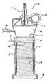
- FIG. 2is a cross-sectional view of an auto-thermal reactor for the fuel processing system shown in FIG. 1, according to an embodiment of the present invention.
- FIG. 3is a cross-sectional view of a tail gas combustor for use in a fuel cell engine, according to an embodiment of the present invention.
- FIG. 2is a cross-sectional view of an auto-thermal reactor (ATR) 70 including an outer housing 78 that can be used as the reactor 14 in the fuel processing system 10 .
- the ATR 70can be a steam reformer.
- the ATR 70employs catalysts that use steam and air to convert a liquid hydrocarbon fuel, such as gasoline, into a hydrogen-rich gas stream or reformate.
- the ATR 70includes a liquid fuel injector 72 that receives the liquid hydrocarbon fuel on the line 16 , and an inlet pipe 74 that receives the air/steam mixture on the line 18 .
- the liquid hydrocarbon fuel from the injector 72is sprayed into a mixing region 80 .
- the air/steam mixture from the pipe 74is received by a flow distribution device 76 that distributes it into the mixing region 80 where it mixes with the sprayed fuel.
- the temperature of the air/steam mixtureis 500-700° C. so that the liquid fuel quickly vaporizes within the mixing region 80 .
- the distribution device 76is cold, the air entering the pipe 74 is cold, and there is no heat to generate steam.
- the heat required to raise the temperature of the air/steam mixture entering the pipe 74is provided by the heat exchanger 20 .
- the heat for the heat exchanger 20is provided by the reformate gas on the line 44 from the operation in the reactor 14 . Therefore, some external heat source must be provided to raise the temperature of the catalysts within the reactor 14 to their operating temperature to generate the steam.
- an electrically heated catalyst (EHC) region 84is provided so that the catalytic reaction within the ATR 70 is initiated quickly at a variety of ambient conditions with minimal mass, volume, pressure drop and parasitic energy.
- the EHC region 84includes a catalyzed substrate or monolith through which the fuel mixture from the mixing region 80 flows.
- the catalystis deposited on the monolith within the EHC region 84 by any conventional technique.
- the catalyzed monolith in the EHC region 84provides a nearly immediate catalytic reaction at system start-up so that exothermic heat is generated very quickly.
- the catalyzed monolithcan employ any catalyst, such as a light-off platinum catalyst, suitable for the purposes discussed herein.
- a catalystsuch as a light-off platinum catalyst, suitable for the purposes discussed herein.
- the slippage of unreacted hydrocarbons during start-upcan be reduced by selecting an EHC with minimal thermal mass and a light-off catalyst having a minimal temperature.
- the EHC region 84receives an external electrical signal from an electrical input 82 . Once the catalyst reaction is sustained, the EHC region 84 will typically be turned off.
- a thermocouple 88or other suitable device, can be provided to measure the temperature of the various monoliths within the housing 78 proximate the EHC region 84 so that the system 10 knows when to turn off the EHC region 84 once it reaches the operating temperature of the catalyst.
- the size of the EHC region 84is application specific in that different fuels and different catalysts may require different sized EHC regions.
- the EHC region 84includes an electric heater.
- the heatermay or may not be catalyzed.
- the EHC region 84can include any suitable device that electrically heats the fuel mixture at system start-up.
- the EHC region 84is also used to supply heat energy to vaporize the liquid fuel within the mixing region 80 .
- the back radiation and conduction from the reaction in the EHC region 84 and the downstream catalystswill support liquid vaporization within the mixing region 80 until the steam/air mixture entering the inlet pipe 74 reaches a sufficient temperature to directly vaporize the liquid fuel spray from the injector 72 .
- the heat from the catalytic reaction in the EHC region 84could lead to auto-ignition of the fuel mixture within the mixing region 80 , which could damage the fuel injector 72 and the flow distribution device 76 and form soot therein.
- a thin un-catalyzed substrate 86is positioned before the EHC region 84 , as shown.
- the substrate 86acts as a radiant shield that blocks much of the heat from entering the flow distribution device 76 .
- the substrate 86absorbs radiant and conductive heat, and also acts to vaporize the fuel from the injector 72 that passes through the mixing region 80 once the ATR 70 is at its operating temperature.
- the substrate 86can be made of various materials, such as a ceramic, for example cordierite, or a high temperature metal alloy, such as stainless steel. Alternately, the substrate 86 can be a heat resistant foam or a honeycomb structure.
- the reformate gas flowpasses through the substrate 86 and the EHC region 84 , and enters a light-off catalyst region 90 .
- the EHC region 84is part of a forward portion of the catalyst monolith within the light-off catalyst region 90 , where only that part of the light-off catalyst monolith is electrically heated.
- the light-off catalyst region 90includes a suitable catalyst, such as a platinum-rhodium catalyst, mounted on a suitable substrate or monolith depending on the application requirements. Foams or other structures can also be used that induce gas-to-catalyst surface interaction and provide reaction stability.
- the gas reformate flowpasses through the catalyst region 90 and into a main catalyst region 92 .
- the main catalyst region 92includes a 600 cells per square inch (CPSI) parallel channel monolith made of cordierite having a similar catalyst as the light-off catalyst.
- the main catalystcould be made of other materials and geometric configurations, as would be well understood to those skilled in the art.
- the main catalyst region 92includes a catalyst that is a steam reforming catalyst, i.e., is not a partial oxidation catalyst that provides an exothermic reaction.
- the reformate gasthen flows through a radiant shield 96 and into the remaining portions of the fuel processing system 10 , as discussed above.
- the hydrocarbon fuelcan be reacted catalytically in the ATR 70 with only air, i.e., without steam, but the catalyst must typically be at least 300° C. and preferably above 400° C. Without steam, the ATR catalyst undergoes partial oxidization of the liquid fuel. Therefore, sufficient air must be provided, i.e., O/C>1. Otherwise sooting and/or unburned hydrocarbons will be produced which will potentially damage both the ATR catalyst and other catalysts downstream, such as the catalysts in the WGS reactor 48 . However, the reaction is extremely exothermic. If operated too close to stoichiometry, i.e., O/C ⁇ 3, the temperature of the ATR catalyst will exceed material limits.
- a metal electrically-heated catalyst operationis limited to about 950° C., where less than 900° C. is desired. This limits the rich O/C operation window of the ATR 70 during this initial no-steam start period to between 1.0 and 1.1. Starting the ATR 70 with sufficient excess air (lean) is another alternative, provided there are no downstream catalysts that are degraded with exposure to oxygen, such as a copper-zinc catalyst-based WGS reactor.
- watercould be injected into the mixing region 80 by a spray injector 94 , so the water is atomized along with the fuel.
- the fuel and waterwould be metered by the injectors 72 and 94 , respectively.
- Table I belowprovides the reaction temperatures and methane levels at two atmospheres of pressure with and without water at a steam to carbon ratio (S/C) of 1.
- S/Csteam to carbon ratio
- the reaction temperatureswill create durability challenges, i.e., greater than 900° C.
- FIG. 3is a cross-sectional view of a tail gas combustor 100 including an outer housing 98 .
- the tail-gas combustor 100is the combustor 30 that provides the heat to form steam.
- the combustor 100is capable of operating on liquid fuel, liquid fuel and a node exhaust gas or anode exhaust gas alone.
- the combustor 100can use liquid fuel to generate heat during system start-up to preheat components within the fuel processor system.
- the combustor 100combusts anode exhaust gas using the cathode exhaust gas as an oxidant. In some applications, the combustor 100 could combust liquid fuel and the anode exhaust gas during normal operation if needed.
- the combustor 100needs to supply the heat input required at the desired temperature to the desired reaction, minimize compressor demands, minimize pressure drop, meet emissions targets, and meet start-up and transient performance requirements.
- the combustor 100combusts liquid fuel catalytically during start-up while maintaining a controlled combustion process using liquid fuel and/or the anode exhaust gas during normal operation to maintain control of the catalyst bed temperature, as well as to minimize the potential for flame in the inlet mixing zone.
- a directly coupled injector to a combustion housingit will be critical to avoid a flame within a mixing region 102 that would result in a potentially severe environment for the metering device that could potentially cause component failure.
- the fuelis sprayed into the mixing region 102 of the combustor 100 through a liquid fuel injector 104 .
- Airenters the mixing region 102 through an inlet pipe 108 .
- the mixing region 102includes a tangential air injection region 110 , an air and fuel mixing region 112 and a radial air injection region 114 , such as a gap.
- the region 114could include orifices around its circumference.
- the fuelenters the injection region 110 in an onion-shaped flow pattern where it is pulled apart by the air from the inlet pipe 108 .
- the airis injected tangentially into the region 110 in order to induce high sheer to break up the fuel into a fine mist of particles that enter the region 112 .
- the air from a pipe 120is also radially injected into the region 114 .
- Anode exhaust gasis introduced into a chamber 116 in the combustor 100 through a pipe 118 and cathode exhaust gas is introduced into the chamber 116 through a pipe 120 .
- the pipe 108 and the cathode exhaust gas pipe 120could be combined.
- An annular gap 122is provided to mix the anode and cathode exhaust gas before they are injected into the chamber 116 .
- the fuel mixture and/or the cathode/anode exhaust gas mixturepasses through a radiant shield 130 similar to the radiant shield 86 .
- the radiant shield 130 or 86is a 40 ppli (pore per linear inch) reticulated foam structure made of yttria-zirconia-alumina (YZA), although it could also be made of many alternate materials, such as silicon carbide, zirconia toughened alumina or structures, such as a woven metal matrix, parallel channel monolith, screens, etc., depending on the mixing and distribution requirements.
- YZAyttria-zirconia-alumina
- the fuel mixturethen flows through an EHC region 134 similar to the region 84 above.
- the EHC region 134 or 84includes a metal honeycomb structure having a density of about 350 CPSI.
- the EHC region 134employs a suitable catalyst, such as palladium, although other precious metals can be used.
- the EHC region 134is used to supply energy to vaporize the liquid within the fuel mixture, and initiate the exothermic reaction. Once the reaction is sustained, the EHC region 134 will under most conditions be turned off, and the back radiation and conduction from the reaction in the EHC region 134 and the downstream catalysts will support liquid vaporization within the chamber 116 and/or the mixing region 102 .
- the EHC region 134could use the distribution foam temperature feed back to control the EHC power cycle.
- the EHC region 134could be just an electrical heater.
- the catalyst region 136 or 90is a 400 ppi reticulated foam.
- the catalyst region 136could use a platinum/palladium catalyst, although other precious metals or combinations of precious metals can be used depending on the particular application and the economic trade off.
- geometric foams or structuresare also possible, as described above, in order to induce turbulence and improve reaction stability.
- the fuel mixturethen passes to a main catalyst region 138 similar to the region 92 above.
- the main catalyst region 138 or 92includes a 600 cspi parallel channel monolith made of cordierite and having a similar catalyst as the catalyst for the region 136 .
- the main catalyst region 138could include alternative materials or geometric configurations as discussed herein.
- the fuel mixturethen continues through another radiant shield 140 .
- a mid-stage air inlet pipe 142receives air from a suitable location (not shown) and distributes it to the full circumference of an annular gap 144 to mix the air with the fuel mixture passing through the radiant shield 140 in a mixing chamber 146 .
- the second stage airallows more of the hydrogen that may otherwise not have been combusted to be combined with air for further catalytic combustion.
- the fuel mixturethen passes from the mixing chamber 146 to a radiant shield and flow distribution zone 148 . From there, the fuel mixture passes through another catalyst region 150 to provide further combustion.
- the described design strategy of the inventioncombusts the fuel in stages to maintain control of the reaction temperature for heat integration, as well as avoid ignition on the hot catalyst surface and the resulting flame propagation into the inlet region resulting in component failure or local hot regions in the catalyst resulting in catalyst bed degradation or emissions.
- the staging operationavoids the potential for flammable mixtures that allow for a reduction in pressure drop and the potential for interstage heat exchangers to operate closer to stoichiometry resulting in a potentially lower air requirement.
Landscapes
- Chemical & Material Sciences (AREA)
- Chemical Kinetics & Catalysis (AREA)
- Engineering & Computer Science (AREA)
- Organic Chemistry (AREA)
- Combustion & Propulsion (AREA)
- Mechanical Engineering (AREA)
- General Engineering & Computer Science (AREA)
- Health & Medical Sciences (AREA)
- General Health & Medical Sciences (AREA)
- Inorganic Chemistry (AREA)
- Hydrogen, Water And Hydrids (AREA)
Abstract
Description
- 1. Field of the Invention[0001]
- This invention relates generally to a primary reactor for a fuel processor system and, more particularly, to a primary reactor for a fuel processor system, where the reactor includes an electrically heated catalyst for improved system start-up.[0002]
- 2. Discussion of the Related Art[0003]
- Hydrogen is a very attractive source of fuel because it is clean and can be used to efficiently produce electricity in a fuel cell. The automotive industry expends significant resources in the development of hydrogen fuel cells as a source of power for vehicles. Such vehicles would be more efficient and generate fewer emissions than today's vehicles employing internal combustion engines.[0004]
- A hydrogen fuel cell is an electrochemical device that includes an anode and a cathode with an electrolyte therebetween. The anode receives a hydrogen gas and the cathode receives an oxygen gas. The hydrogen gas is ionized in the anode to generate free hydrogen protons and electrons. The hydrogen protons pass through the electrolyte to the cathode, where they react with the oxygen and the electrons in the cathode to generate water as a by-product. The electrons from the anode cannot pass through the electrolyte, and thus are directed through a load to perform work before being sent to the cathode. The work acts to operate the vehicle. Many fuels cells are typically combined in a fuel cell stack to generate the desired power.[0005]
- Proton exchange membrane fuel cells (PEMFCs) are a popular fuel cell for vehicles. In a PEMFC, hydrogen (H[0006]2) is the anode reactant, i.e., fuel, and oxygen is the cathode reactant, i.e., oxidant. The cathode reactant can be either pure oxygen or air (a mixture of O2and N2). The PEMFC generally includes a solid polymer electrolyte proton conducting membrane, such as a perflurosulfonic acid membrane. The anode and cathode typically include finely divided catalytic particles, usually platinum (Pt), supported on carbon particles and mixed with an isomer. The combination of the anode, cathode and membrane define a membrane electrode assembly (MEA). MEAs are relatively expensive to manufacturer and require certain conditions for effective operation. These conditions include proper water management and humidification, and control of catalyst poisoning constituents, such as carbon monoxide (CO).
- In vehicle fuel cell applications, it is desirable to use: a liquid fuel, such as alcohols (methanol or ethanol), hydrocarbons (gasoline), and/or mixtures thereof, such as blends of ethanol/methanol and gasoline, as a source of hydrogen for the fuel cell. Usually, hydrocarbon-based liquid fuels are dissociated within a chemical fuel processor system or reformer to release the hydrogen therefrom for fueling the cell. The fuel processor system contains one or more reactors where the fuel is reacted chemically to break down the hydrocarbons in the fuel with water and/or air to generate a reformate gas comprising hydrogen and carbon monoxide, methane, nitrogen, carbon dioxide and water as by-products.[0007]
- Generally, the reactor is a steam reformer or auto-thermal reactor (ATR). The steam reformer requires an external heat source to generate the heat required to dissociate the hydrocarbon fuel. The ATR includes a partial oxidation (POX) reactor and a steam reformer. The POX reactor includes a catalyst that generates heat by an exothermic reaction to heat the steam reformer and dissociate the hydrocarbon fuel. A steam reformer typically provides a higher conversion percentage of the hydrocarbon fuel into hydrogen than the POX reactor. However, a steam reformer requires a significant heat input than the POX reactor.[0008]
- The known fuel processor systems also typically include downstream reactors, such as water-gas shift (WGS) reactors and preferential oxidation (PROX) reactors. The WGS and PROX reactors are necessary to convert carbon monoxide (CO) to carbon dioxide (CO[0009]2) in the reformate gas because carbon monoxide contaminates the catalytic particles in the PEM fuel cell stack. It is desirable that the carbon monoxide in the reformate gas be less than 100 ppm to be suitable for fuel cell applications. The WGS reactor employs catalysts that convert carbon monoxide and water to carbon dioxide and hydrogen. The PROX reactor employs catalysts that selectively oxidize carbon monoxide (using oxygen from air as an oxidant) in the presence of hydrogen to produce carbon dioxide (CO2).
- The reformate gas stream passes through the fuel cell stack that utilizes the hydrogen in the reformate gas and oxygen from air. An anode exhaust gas and a cathode exhaust gas are discharged from the stack. The anode exhaust gas is the anode input gas stream minus the hydrogen used by the stack and the cathode exhaust gas is a depleted oxygen stream. The two exhaust gas streams, in some designs, are then sent to a tail gas combustor, which consumes the anode exhaust gas using oxygen from air or the cathode exhaust gas. The combustor energy can be employed to integrate heat into the fuel processor system, run an expander, run a co-generation process or be exhausted.[0010]
- FIG. 1 is a plan view of a[0011]
fuel processor system 10 for generating hydrogen to be used in a fuel cell engine of the type discussed above. A hydrocarbon fuel, such as gasoline, natural gas, methane, propane, methanol and/or mixtures thereof, is fed to a primary reactor14, such as an ATR, from a suitable source (not shown) on aline 16. The hydrocarbon fuel reacts with a steam/air mixture received on aline 18 from aheat exchanger 20 to dissociate the hydrogen from the fuel and generate a hydrogen-rich reformate gas. The reactor14 includes a steam reforming and/or partial oxidation catalyst suitable for the specific fuel being used. The operating temperature of the reactor14 depends on the nature of the fuel and the relative compositions of fuel, air and water, and is typically between 300° C. and 800° C. The reformate gas exiting the primary reactor14 on aline 44 contains primarily hydrogen, nitrogen, carbon monoxide, carbon dioxide, water and possibly methane. - The steam for the steam/air mixture is generated in a[0012]
heat exchanger 24, where liquid water provided on aline 26 is heated and vaporized in theheat exchanger 24 by a hot exhaust stream on aline 28 from acombustor 30, such as a tail gas combustor. The steam exits theheat exchanger 24 on a line34 and is mixed with compressed air provided on aline 36 in a mixing zone orvalve 38. The steam/air mixture exits the zone orvalve 38 on aline 40 to be sent to theheat exchanger 20 to form the hot steam/air mixture on theline 18 sent to the reactor14. The heat required to raise the temperature of the steam on theline 40 in theheat exchanger 20 is generated by the reformate gas from the reactor14 on theline 44. Alternatively, the air and water can be heated separately and mixed either within or before the primary reactor14. - It is necessary to convert carbon monoxide to carbon dioxide in the reformate gas being used in a fuel cell stack because carbon monoxide contaminates the catalyst particles used therein. The carbon monoxide concentration of the reformate gas on the[0013]
line 44 is typically between about 5 mole percent and about 20 mole percent. Typically, fuel processing systems employ WGS reactors to reduce the carbon monoxide in the reformate gas flow. The reformate gas on theline 44 is cooled in theheat exchanger 20 to the operational temperature of aWGS reactor 48. The cooled reformate gas is then applied to theW GS reactor 48 on aline 50, where carbon monoxide and water are converted to hydrogen and carbon dioxide by a catalyst reaction process that is well understood in the art. Conventional catalysts, such as Fe3O4/Cr2O3for high temperature shifts or CuO/ZnO/Al2O3for low temperature shifts, may be used, as well as any other known WGS catalyst. - The WGS[0014]
reactor 48 can be a high temperature WGS reactor (320° C.-500° C.), a medium temperature WGS reactor (250° C.-400° C.), or a low temperature WGS reactor (150° C.-250° C.). Alternately, thereactor 48 can include a combination of high, medium and low temperature WGS reactors that employ a technique for cooling the reformate gas as it flows between the different temperature reaction zones. Generally, the temperature of theWGS reactor 48 decreases with the direction of the reformate gas flow. - The WGS[0015]
reactor 48 generates a reformate gas flow on aline 52 that is primarily hydrogen, nitrogen, carbon monoxide, carbon dioxide and water. The reformate gas will typically include about 0.3-3 mole percent CO depending on the exit temperature of theWGS reactor 48, the space velocity of the reformate gas on theline 50, the steam to carbon ratio and the catalyst used. The reformate gas exits the WGSreactor 48 on theline 52 with less carbon monoxide and more hydrogen than the reformate gas on theline 50. However, theWGS reactor 48 cannot remove enough of the carbon monoxide in the reformate gas for the PEM fuel cell stack. Therefore, the reformate gas on theline 52 is sent to aPROX reactor 54. The operating temperature of the WGS reactor is greater than the operating temperature of thePROX reactor 54. Therefore, the temperature of the reformate gas exiting theWGS reactor 48 is above the operating temperature of thePROX reactor 54. Thus, aheat exchanger 56 is provided to cool the reformate gas on theline 52 to a reduced temperature on aline 58. - The[0016]
PROX reactor 54 removes more of the carbon monoxide in the reformate gas that would otherwise contaminate the catalytic particles in the PEM fuel cell. ThePROX reactor 54 selectively oxidizes carbon monoxide in the presence of hydrogen to produce carbon dioxide (CO2) using oxygen from air as an oxidant. The reformate gas from thePROX reactor 54 is then provided to a fuelcell engine stack 60 online 62, or is stored as compressed gas in a container for future use. Some primary reactor designs preheat a certain gas, such as nitrogen, that flows through the catalyst monolith to heat the catalyst therein at system start up. However, the known techniques for heating the catalyst monolith in the reactor at system start-up have heretofore been relatively inadequate. - State of the art primary reactors in a fuel processor system typically have a relatively long start-up time before the reactor becomes hot enough to dissociate the hydrocarbon fuel to produce hydrogen. The long start-up time is directly related to the relatively large mass and large volume of the catalyst monoliths in the reactor because of the energy needed to get the catalyst monoliths up to their operating temperature. It is desirable to reduce the start-up time of the fuel processor system by quickly heating the catalysts in the primary reactor when the system is turned on.[0017]
- In accordance with the teachings of the present invention, a primary reactor for a fuel processor system is disclosed that employs steam and air to convert a liquid hydrocarbon fuel, such as gasoline, into a hydrogen-rich gas reformate stream. The liquid fuel and the air/steam mixture are mixed in a mixing region within the reactor to vaporize the liquid fuel. The fuel mixture is then directed through an electrically heated catalyst region that heats the mixture to the operating temperature of a light-off catalyst at system start-up. The electrically heated catalyst region can include the light-off catalyst. The heated fuel mixture is then directed through a light-off catalyst monolith where the hydrocarbon fuel is dissociated. Once the fuel mixture is heated to the operating temperature of the light-off catalyst, the electrically heated catalyst region is turned off because the exothermic reaction in the light-off catalyst monolith generates the heat necessary to sustain the catalytic reaction. The fuel mixture is then directed through a main catalyst monolith to provide steam reforming where the fuel is further dissociated to generate the hydrogen gas.[0018]
- The electrically heated catalyst region can employ various configurations to quickly electrically heat the fuel mixture at system start-up. For example, the electrically heated catalyst region can be a front portion of the light-off catalyst monolith that is electrically heated. Alternately, the electrically heated catalyst region can be an electric heater positioned before the light-off catalyst monolith that may or may not be catalyzed. Further, the electrically heated catalyst region is also used to supply heat energy to vaporize the liquid fuel within the mixing region.[0019]
- The electrically heated catalyst of the invention can be employed in a tail-gas combustor that burns the anode exhaust gas. In the tail-gas combustor, the electrically heated catalyst region is also employed to heat the catalyst that reacts with the hydrogen and oxygen to generate water.[0020]
- Additional advantages and features of the present invention will become apparent from the following description and appended claims, taken in conjunction with the accompanying drawings.[0021]
- FIG. 1 is a schematic plan view of a fuel processing system;[0022]
- FIG. 2 is a cross-sectional view of an auto-thermal reactor for the fuel processing system shown in FIG. 1, according to an embodiment of the present invention; and[0023]
- FIG. 3 is a cross-sectional view of a tail gas combustor for use in a fuel cell engine, according to an embodiment of the present invention.[0024]
- The following discussion of the embodiments of the invention directed to a primary reactor and a tail gas combustor for a fuel processing system is merely exemplary in nature, and is in no way intended to limit the invention or its applications or uses.[0025]
- FIG. 2 is a cross-sectional view of an auto-thermal reactor (ATR)[0026]70 including an
outer housing 78 that can be used as the reactor14 in thefuel processing system 10. In an alternative embodiment, theATR 70 can be a steam reformer. As will be discussed below, theATR 70 employs catalysts that use steam and air to convert a liquid hydrocarbon fuel, such as gasoline, into a hydrogen-rich gas stream or reformate. TheATR 70 includes aliquid fuel injector 72 that receives the liquid hydrocarbon fuel on theline 16, and aninlet pipe 74 that receives the air/steam mixture on theline 18. The liquid hydrocarbon fuel from theinjector 72 is sprayed into a mixingregion 80. The air/steam mixture from thepipe 74 is received by aflow distribution device 76 that distributes it into the mixingregion 80 where it mixes with the sprayed fuel. During steady-state operation, the temperature of the air/steam mixture is 500-700° C. so that the liquid fuel quickly vaporizes within the mixingregion 80. - At system start-up, the[0027]
distribution device 76 is cold, the air entering thepipe 74 is cold, and there is no heat to generate steam. The heat required to raise the temperature of the air/steam mixture entering thepipe 74 is provided by theheat exchanger 20. The heat for theheat exchanger 20 is provided by the reformate gas on theline 44 from the operation in the reactor14. Therefore, some external heat source must be provided to raise the temperature of the catalysts within the reactor14 to their operating temperature to generate the steam. - It is desirable to raise the temperature of the catalysts within the[0028]
ATR 70 to their operating temperature very quickly at system start-up so that hydrogen is produced as soon as possible. According to the invention, an electrically heated catalyst (EHC)region 84 is provided so that the catalytic reaction within theATR 70 is initiated quickly at a variety of ambient conditions with minimal mass, volume, pressure drop and parasitic energy. TheEHC region 84 includes a catalyzed substrate or monolith through which the fuel mixture from the mixingregion 80 flows. The catalyst is deposited on the monolith within theEHC region 84 by any conventional technique. The catalyzed monolith in theEHC region 84 provides a nearly immediate catalytic reaction at system start-up so that exothermic heat is generated very quickly. The catalyzed monolith can employ any catalyst, such as a light-off platinum catalyst, suitable for the purposes discussed herein. The slippage of unreacted hydrocarbons during start-up can be reduced by selecting an EHC with minimal thermal mass and a light-off catalyst having a minimal temperature. - The[0029]
EHC region 84 receives an external electrical signal from anelectrical input 82. Once the catalyst reaction is sustained, theEHC region 84 will typically be turned off. Athermocouple 88, or other suitable device, can be provided to measure the temperature of the various monoliths within thehousing 78 proximate theEHC region 84 so that thesystem 10 knows when to turn off theEHC region 84 once it reaches the operating temperature of the catalyst. The size of theEHC region 84 is application specific in that different fuels and different catalysts may require different sized EHC regions. - In one embodiment, the[0030]
EHC region 84 includes an electric heater. The heater may or may not be catalyzed. However, it is stressed that theEHC region 84 can include any suitable device that electrically heats the fuel mixture at system start-up. - During ATR start-up, the[0031]
EHC region 84 is also used to supply heat energy to vaporize the liquid fuel within the mixingregion 80. The back radiation and conduction from the reaction in theEHC region 84 and the downstream catalysts will support liquid vaporization within the mixingregion 80 until the steam/air mixture entering theinlet pipe 74 reaches a sufficient temperature to directly vaporize the liquid fuel spray from theinjector 72. - The heat from the catalytic reaction in the[0032]
EHC region 84 could lead to auto-ignition of the fuel mixture within the mixingregion 80, which could damage thefuel injector 72 and theflow distribution device 76 and form soot therein. To minimize the auto-ignition risk, a thinun-catalyzed substrate 86 is positioned before theEHC region 84, as shown. Thesubstrate 86 acts as a radiant shield that blocks much of the heat from entering theflow distribution device 76. Thesubstrate 86 absorbs radiant and conductive heat, and also acts to vaporize the fuel from theinjector 72 that passes through the mixingregion 80 once theATR 70 is at its operating temperature. Thesubstrate 86 can be made of various materials, such as a ceramic, for example cordierite, or a high temperature metal alloy, such as stainless steel. Alternately, thesubstrate 86 can be a heat resistant foam or a honeycomb structure. - The reformate gas flow passes through the[0033]
substrate 86 and theEHC region 84, and enters a light-off catalyst region 90. In one embodiment, theEHC region 84 is part of a forward portion of the catalyst monolith within the light-off catalyst region 90, where only that part of the light-off catalyst monolith is electrically heated. The light-off catalyst region 90 includes a suitable catalyst, such as a platinum-rhodium catalyst, mounted on a suitable substrate or monolith depending on the application requirements. Foams or other structures can also be used that induce gas-to-catalyst surface interaction and provide reaction stability. - The gas reformate flow passes through the[0034]
catalyst region 90 and into amain catalyst region 92. In one embodiment, themain catalyst region 92 includes a 600 cells per square inch (CPSI) parallel channel monolith made of cordierite having a similar catalyst as the light-off catalyst. The main catalyst could be made of other materials and geometric configurations, as would be well understood to those skilled in the art. In one design, themain catalyst region 92 includes a catalyst that is a steam reforming catalyst, i.e., is not a partial oxidation catalyst that provides an exothermic reaction. The reformate gas then flows through aradiant shield 96 and into the remaining portions of thefuel processing system 10, as discussed above. - The hydrocarbon fuel can be reacted catalytically in the[0035]
ATR 70 with only air, i.e., without steam, but the catalyst must typically be at least 300° C. and preferably above 400° C. Without steam, the ATR catalyst undergoes partial oxidization of the liquid fuel. Therefore, sufficient air must be provided, i.e., O/C>1. Otherwise sooting and/or unburned hydrocarbons will be produced which will potentially damage both the ATR catalyst and other catalysts downstream, such as the catalysts in theWGS reactor 48. However, the reaction is extremely exothermic. If operated too close to stoichiometry, i.e., O/C≈3, the temperature of the ATR catalyst will exceed material limits. Typically, a metal electrically-heated catalyst operation is limited to about 950° C., where less than 900° C. is desired. This limits the rich O/C operation window of theATR 70 during this initial no-steam start period to between 1.0 and 1.1. Starting theATR 70 with sufficient excess air (lean) is another alternative, provided there are no downstream catalysts that are degraded with exposure to oxygen, such as a copper-zinc catalyst-based WGS reactor. - For those times when the operating temperature is at O/C>1 and below temperature limits, water could be injected into the mixing[0036]
region 80 by aspray injector 94, so the water is atomized along with the fuel. The fuel and water would be metered by theinjectors - Table I below provides the reaction temperatures and methane levels at two atmospheres of pressure with and without water at a steam to carbon ratio (S/C) of 1. As can be seen, even with these very stringent mixing requirements, the reaction temperatures will create durability challenges, i.e., greater than 900° C. The addition of water into the mixing[0037]
region 80 helps to reduce the reactor temperature at which acceptably low methane levels (<100 ppm) can be obtained. For example, without steam, 8000 ppm methane is formed at 830° C., whereas with a water level of S/C=1 and a reactor temperature of 800° C., the methane level is only 140 ppm. It is noted that when thecatalyst regions TABLE I O/C T(C) CH4(molar) (S/C = 0, dry) 1.0 830 8000 ppm 1.1 930 300 ppm 1.2 1060 9 ppm (S/C = 1, 1.10 650 13000 ppm with water) 1.21 703 2000 ppm 1.32 800 140 ppm - FIG. 3 is a cross-sectional view of a[0038]
tail gas combustor 100 including anouter housing 98. In one embodiment, the tail-gas combustor 100 is the combustor30 that provides the heat to form steam. Thecombustor 100 is capable of operating on liquid fuel, liquid fuel and a node exhaust gas or anode exhaust gas alone. Thecombustor 100 can use liquid fuel to generate heat during system start-up to preheat components within the fuel processor system. During steady-state operation, thecombustor 100 combusts anode exhaust gas using the cathode exhaust gas as an oxidant. In some applications, thecombustor 100 could combust liquid fuel and the anode exhaust gas during normal operation if needed. - The[0039]
combustor 100 needs to supply the heat input required at the desired temperature to the desired reaction, minimize compressor demands, minimize pressure drop, meet emissions targets, and meet start-up and transient performance requirements. According to the invention, thecombustor 100 combusts liquid fuel catalytically during start-up while maintaining a controlled combustion process using liquid fuel and/or the anode exhaust gas during normal operation to maintain control of the catalyst bed temperature, as well as to minimize the potential for flame in the inlet mixing zone. By using a directly coupled injector to a combustion housing, it will be critical to avoid a flame within a mixingregion 102 that would result in a potentially severe environment for the metering device that could potentially cause component failure. - During those times when the[0040]
combustor 100 burns liquid fuel, the fuel is sprayed into the mixingregion 102 of thecombustor 100 through aliquid fuel injector 104. Air enters the mixingregion 102 through aninlet pipe 108. The mixingregion 102 includes a tangentialair injection region 110, an air andfuel mixing region 112 and a radialair injection region 114, such as a gap. Alternatively, theregion 114 could include orifices around its circumference. The fuel enters theinjection region 110 in an onion-shaped flow pattern where it is pulled apart by the air from theinlet pipe 108. The air is injected tangentially into theregion 110 in order to induce high sheer to break up the fuel into a fine mist of particles that enter theregion 112. The air from apipe 120 is also radially injected into theregion 114. - Anode exhaust gas is introduced into a[0041]
chamber 116 in thecombustor 100 through apipe 118 and cathode exhaust gas is introduced into thechamber 116 through apipe 120. In an alternate design, depending on system specifications and architectures, thepipe 108 and the cathodeexhaust gas pipe 120 could be combined. Anannular gap 122 is provided to mix the anode and cathode exhaust gas before they are injected into thechamber 116. - The fuel mixture and/or the cathode/anode exhaust gas mixture passes through a[0042]
radiant shield 130 similar to theradiant shield 86. In one embodiment, theradiant shield - The fuel mixture then flows through an[0043]
EHC region 134 similar to theregion 84 above. In one embodiment, theEHC region EHC region 134 employs a suitable catalyst, such as palladium, although other precious metals can be used. During start-up, theEHC region 134 is used to supply energy to vaporize the liquid within the fuel mixture, and initiate the exothermic reaction. Once the reaction is sustained, theEHC region 134 will under most conditions be turned off, and the back radiation and conduction from the reaction in theEHC region 134 and the downstream catalysts will support liquid vaporization within thechamber 116 and/or the mixingregion 102. Under some conditions, theEHC region 134 could use the distribution foam temperature feed back to control the EHC power cycle. Depending on the application requirements, theEHC region 134 could be just an electrical heater. - The fuel mixture exits the[0044]
EHC region 134 and passes into a light-off catalyst region 136 similar to theregion 90 above. In one embodiment, thecatalyst region catalyst region 136 could use a platinum/palladium catalyst, although other precious metals or combinations of precious metals can be used depending on the particular application and the economic trade off. Alternatively, geometric foams or structures are also possible, as described above, in order to induce turbulence and improve reaction stability. - The fuel mixture then passes to a[0045]
main catalyst region 138 similar to theregion 92 above. In one embodiment, themain catalyst region region 136. Themain catalyst region 138 could include alternative materials or geometric configurations as discussed herein. The fuel mixture then continues through anotherradiant shield 140. - A mid-stage[0046]
air inlet pipe 142 receives air from a suitable location (not shown) and distributes it to the full circumference of anannular gap 144 to mix the air with the fuel mixture passing through theradiant shield 140 in amixing chamber 146. The second stage air allows more of the hydrogen that may otherwise not have been combusted to be combined with air for further catalytic combustion. The fuel mixture then passes from the mixingchamber 146 to a radiant shield and flowdistribution zone 148. From there, the fuel mixture passes through anothercatalyst region 150 to provide further combustion. - The described design strategy of the invention combusts the fuel in stages to maintain control of the reaction temperature for heat integration, as well as avoid ignition on the hot catalyst surface and the resulting flame propagation into the inlet region resulting in component failure or local hot regions in the catalyst resulting in catalyst bed degradation or emissions. The staging operation avoids the potential for flammable mixtures that allow for a reduction in pressure drop and the potential for interstage heat exchangers to operate closer to stoichiometry resulting in a potentially lower air requirement.[0047]
- The foregoing discussion discloses and describes merely exemplary embodiments of the present invention. One skilled in the art will readily recognize from such discussion and from the accompanying drawings and claims that various changes, modifications and variations can be made therein without departing from the spirit and scope of the invention as defined in the following claims.[0048]
Claims (32)
Priority Applications (1)
| Application Number | Priority Date | Filing Date | Title |
|---|---|---|---|
| US10/360,996US7862631B2 (en) | 2003-02-07 | 2003-02-07 | Fuel processor primary reactor and combustor startup via electrically-heated catalyst |
Applications Claiming Priority (1)
| Application Number | Priority Date | Filing Date | Title |
|---|---|---|---|
| US10/360,996US7862631B2 (en) | 2003-02-07 | 2003-02-07 | Fuel processor primary reactor and combustor startup via electrically-heated catalyst |
Publications (2)
| Publication Number | Publication Date |
|---|---|
| US20040154222A1true US20040154222A1 (en) | 2004-08-12 |
| US7862631B2 US7862631B2 (en) | 2011-01-04 |
Family
ID=32824108
Family Applications (1)
| Application Number | Title | Priority Date | Filing Date |
|---|---|---|---|
| US10/360,996Expired - Fee RelatedUS7862631B2 (en) | 2003-02-07 | 2003-02-07 | Fuel processor primary reactor and combustor startup via electrically-heated catalyst |
Country Status (1)
| Country | Link |
|---|---|
| US (1) | US7862631B2 (en) |
Cited By (17)
| Publication number | Priority date | Publication date | Assignee | Title |
|---|---|---|---|---|
| US20030162059A1 (en)* | 2002-02-28 | 2003-08-28 | Jon Gelsey | Thermally efficient hydrogen storage system |
| US20040265224A1 (en)* | 2003-06-26 | 2004-12-30 | Vasilis Papavassiliou | Autothermal reactor and method for production of synthesis gas |
| US20050016064A1 (en)* | 2003-07-26 | 2005-01-27 | Agnew Gerard D. | Pre-reformer |
| JP2006068625A (en)* | 2004-09-01 | 2006-03-16 | Casio Comput Co Ltd | Reactor |
| US20060143980A1 (en)* | 2004-12-30 | 2006-07-06 | Conocophillips Company | Reactor and process for making synthesis gas |
| EP1927579A1 (en)* | 2006-11-07 | 2008-06-04 | Delphi Technologies, Inc. | Electrically-heated metal vaporizer for fuel / air preparation in a hydrocarbon reformer assembly |
| WO2008082361A1 (en) | 2007-01-05 | 2008-07-10 | Zemission Ab | A heating device including catalytic burning of liquid fuel |
| US20080268301A1 (en)* | 2007-04-24 | 2008-10-30 | Sung-Chul Lee | Fuel reforming apparatus and its method of driving and fuel cell system including the apparatus |
| WO2009003481A3 (en)* | 2007-07-03 | 2009-10-22 | Heatgear Professional Aps | Catalytic heater |
| EP2198951A3 (en)* | 2008-12-19 | 2010-09-15 | Samsung SDI Co., Ltd. | Reformer |
| FR2944519A1 (en)* | 2009-04-21 | 2010-10-22 | Irma | CATALYTIC REFORM MODULE AND DEVICE, AND METHODS OF MANUFACTURE |
| US20100303681A1 (en)* | 2009-05-28 | 2010-12-02 | In-Hyuk Son | Catalytic combustor and fuel reformer having the same |
| EP2407224A1 (en)* | 2010-07-16 | 2012-01-18 | Samsung SDI Co., Ltd. | Catalytic combustor for a reformer for a fuel cell |
| US20130157203A1 (en)* | 2009-11-20 | 2013-06-20 | CC/ Thermal Technologies Inc. | Gas fired catalytic heater |
| KR102143175B1 (en)* | 2019-12-27 | 2020-08-10 | 국방과학연구소 | Combustor for liquid fuel |
| WO2023154774A3 (en)* | 2022-02-10 | 2023-10-19 | Northwestern University | Systems and methods for efficient electrical generation from liquid fuels |
| EP4462020A1 (en)* | 2023-05-11 | 2024-11-13 | Salzburger Aluminium Aktiengesellschaft | Device for catalytic combustion of hydrogen |
Families Citing this family (12)
| Publication number | Priority date | Publication date | Assignee | Title |
|---|---|---|---|---|
| CN102489221B (en)* | 2011-12-30 | 2014-07-02 | 中国东方电气集团有限公司 | Heating rate controllable electric heating reactor |
| SG11201702330XA (en) | 2014-10-07 | 2017-04-27 | Protonex Technology Corp | Sofc-conduction |
| US10790523B2 (en)* | 2015-10-20 | 2020-09-29 | Upstart Power, Inc. | CPOX reactor control system and method |
| AU2017311409C1 (en) | 2016-08-11 | 2023-04-27 | Upstart Power, Inc. | Planar solid oxide fuel unit cell and stack |
| CA3150382A1 (en) | 2019-08-14 | 2021-02-18 | Upstart Power, Inc. | Sofc-conduction |
| US12000333B2 (en) | 2021-05-14 | 2024-06-04 | AMOGY, Inc. | Systems and methods for processing ammonia |
| US11724245B2 (en) | 2021-08-13 | 2023-08-15 | Amogy Inc. | Integrated heat exchanger reactors for renewable fuel delivery systems |
| AU2022290866A1 (en) | 2021-06-11 | 2023-12-21 | Amogy Inc. | Systems and methods for processing ammonia |
| US11539063B1 (en) | 2021-08-17 | 2022-12-27 | Amogy Inc. | Systems and methods for processing hydrogen |
| US11912574B1 (en) | 2022-10-06 | 2024-02-27 | Amogy Inc. | Methods for reforming ammonia |
| US11795055B1 (en) | 2022-10-21 | 2023-10-24 | Amogy Inc. | Systems and methods for processing ammonia |
| US11866328B1 (en) | 2022-10-21 | 2024-01-09 | Amogy Inc. | Systems and methods for processing ammonia |
Citations (3)
| Publication number | Priority date | Publication date | Assignee | Title |
|---|---|---|---|---|
| US4982564A (en)* | 1988-12-14 | 1991-01-08 | General Electric Company | Turbine engine with air and steam cooling |
| US6077620A (en)* | 1997-11-26 | 2000-06-20 | General Motors Corporation | Fuel cell system with combustor-heated reformer |
| US6232005B1 (en)* | 1997-11-20 | 2001-05-15 | General Motors Corporation | Fuel cell system combustor |
Family Cites Families (6)
| Publication number | Priority date | Publication date | Assignee | Title |
|---|---|---|---|---|
| JPH11130405A (en)* | 1997-10-28 | 1999-05-18 | Ngk Insulators Ltd | Reforming reaction device, catalytic device, exothermic catalytic body used for the same and operation of reforming reaction device |
| US6221327B1 (en)* | 1998-05-15 | 2001-04-24 | Rohm And Haas Company | Catalyst system using flow-through radiation shielding and a process for producing hydrogen cyanide using the same |
| JP2001270704A (en)* | 2000-03-28 | 2001-10-02 | Matsushita Electric Ind Co Ltd | Hydrogen generator |
| JP2001354402A (en)* | 2000-06-08 | 2001-12-25 | Toyota Motor Corp | Fuel reformer |
| US6869456B2 (en)* | 2000-06-27 | 2005-03-22 | Delphi Technologies, Inc. | Method for starting a fast light-off catalytic fuel reformer |
| US7160342B2 (en)* | 2001-02-13 | 2007-01-09 | Delphi Technologies, Inc. | Fuel reformer system |
- 2003
- 2003-02-07USUS10/360,996patent/US7862631B2/ennot_activeExpired - Fee Related
Patent Citations (3)
| Publication number | Priority date | Publication date | Assignee | Title |
|---|---|---|---|---|
| US4982564A (en)* | 1988-12-14 | 1991-01-08 | General Electric Company | Turbine engine with air and steam cooling |
| US6232005B1 (en)* | 1997-11-20 | 2001-05-15 | General Motors Corporation | Fuel cell system combustor |
| US6077620A (en)* | 1997-11-26 | 2000-06-20 | General Motors Corporation | Fuel cell system with combustor-heated reformer |
Cited By (34)
| Publication number | Priority date | Publication date | Assignee | Title |
|---|---|---|---|---|
| US20060188762A1 (en)* | 2002-02-28 | 2006-08-24 | Jon Gelsey | Thermally efficient hydrogen storage system |
| US7108933B2 (en) | 2002-02-28 | 2006-09-19 | Intel Corporation | Thermally efficient hydrogen storage system |
| US20030162059A1 (en)* | 2002-02-28 | 2003-08-28 | Jon Gelsey | Thermally efficient hydrogen storage system |
| US20040265224A1 (en)* | 2003-06-26 | 2004-12-30 | Vasilis Papavassiliou | Autothermal reactor and method for production of synthesis gas |
| US7255840B2 (en)* | 2003-06-26 | 2007-08-14 | Praxair Technology, Inc. | Autothermal reactor and method for production of synthesis gas |
| US7556781B2 (en)* | 2003-07-26 | 2009-07-07 | Rolls-Royce, PLLC | Pre-reformer |
| US20050016064A1 (en)* | 2003-07-26 | 2005-01-27 | Agnew Gerard D. | Pre-reformer |
| US7867301B2 (en) | 2003-07-26 | 2011-01-11 | Rolls-Royce Plc | Pre-reformer |
| US20100055519A1 (en)* | 2003-07-26 | 2010-03-04 | Agnew Gerard D | pre-reformer |
| US7625528B2 (en) | 2003-07-26 | 2009-12-01 | Rolls-Royce Plc | Pre-reformer |
| JP2006068625A (en)* | 2004-09-01 | 2006-03-16 | Casio Comput Co Ltd | Reactor |
| US7381230B2 (en)* | 2004-12-30 | 2008-06-03 | Conocophillips Company | Reactor and process for making synthesis gas |
| US20060143980A1 (en)* | 2004-12-30 | 2006-07-06 | Conocophillips Company | Reactor and process for making synthesis gas |
| EP1927579A1 (en)* | 2006-11-07 | 2008-06-04 | Delphi Technologies, Inc. | Electrically-heated metal vaporizer for fuel / air preparation in a hydrocarbon reformer assembly |
| US7736399B2 (en) | 2006-11-07 | 2010-06-15 | Delphi Technologies, Inc. | Electrically-heated metal vaporizer for fuel/air preparation in a hydrocarbon reformer assembly |
| WO2008082361A1 (en) | 2007-01-05 | 2008-07-10 | Zemission Ab | A heating device including catalytic burning of liquid fuel |
| EP2122246A4 (en)* | 2007-01-05 | 2014-04-30 | Zemission Ab | HEATING DEVICE COMPRISING A CATALYTIC COMBUSTION OF LIQUID FUEL |
| US20100139599A1 (en)* | 2007-01-05 | 2010-06-10 | Zemission Ab | heating device including catalytic burning of liquid fuel |
| US9494316B2 (en)* | 2007-01-05 | 2016-11-15 | Zemission Ab | Heating device including catalytic burning of liquid fuel |
| EP1987876A1 (en)* | 2007-04-24 | 2008-11-05 | Samsung SDI Co., Ltd. | A fuel reforming apparatus, a method of driving said apparatus and a fuel cell system including said apparatus |
| US20080268301A1 (en)* | 2007-04-24 | 2008-10-30 | Sung-Chul Lee | Fuel reforming apparatus and its method of driving and fuel cell system including the apparatus |
| US8003269B2 (en) | 2007-04-24 | 2011-08-23 | Samsung Sdi Co., Ltd. | Fuel reforming apparatus and its method of driving and fuel cell system including the apparatus |
| WO2009003481A3 (en)* | 2007-07-03 | 2009-10-22 | Heatgear Professional Aps | Catalytic heater |
| EP2198951A3 (en)* | 2008-12-19 | 2010-09-15 | Samsung SDI Co., Ltd. | Reformer |
| FR2944519A1 (en)* | 2009-04-21 | 2010-10-22 | Irma | CATALYTIC REFORM MODULE AND DEVICE, AND METHODS OF MANUFACTURE |
| WO2010122077A1 (en)* | 2009-04-21 | 2010-10-28 | Institut Regional Des Materiaux Avances (Irma) | Module and device for catalytic reforming, and manufacturing methods |
| US20100303681A1 (en)* | 2009-05-28 | 2010-12-02 | In-Hyuk Son | Catalytic combustor and fuel reformer having the same |
| US8617269B2 (en) | 2009-05-28 | 2013-12-31 | Samsung Sdi Co., Ltd. | Catalytic combustor and fuel reformer having the same |
| EP2255872A3 (en)* | 2009-05-28 | 2011-05-25 | Samsung SDI Co., Ltd. | Catalytic combustor and fuel reformer having the same |
| US20130157203A1 (en)* | 2009-11-20 | 2013-06-20 | CC/ Thermal Technologies Inc. | Gas fired catalytic heater |
| EP2407224A1 (en)* | 2010-07-16 | 2012-01-18 | Samsung SDI Co., Ltd. | Catalytic combustor for a reformer for a fuel cell |
| KR102143175B1 (en)* | 2019-12-27 | 2020-08-10 | 국방과학연구소 | Combustor for liquid fuel |
| WO2023154774A3 (en)* | 2022-02-10 | 2023-10-19 | Northwestern University | Systems and methods for efficient electrical generation from liquid fuels |
| EP4462020A1 (en)* | 2023-05-11 | 2024-11-13 | Salzburger Aluminium Aktiengesellschaft | Device for catalytic combustion of hydrogen |
Also Published As
| Publication number | Publication date |
|---|---|
| US7862631B2 (en) | 2011-01-04 |
Similar Documents
| Publication | Publication Date | Title |
|---|---|---|
| US7862631B2 (en) | Fuel processor primary reactor and combustor startup via electrically-heated catalyst | |
| JP3088099B2 (en) | Fuel cell device | |
| US7438734B2 (en) | Direct water vaporization for fuel processor startup and transients | |
| JP3349441B2 (en) | Fuel cell device | |
| US7025903B2 (en) | Reformer system process | |
| AU2010253491B2 (en) | Gas generator and processes for the conversion of a fuel into an oxygen-depleted gas and/or hydrogen-enriched gas | |
| US6872379B2 (en) | Method for the reformation of fuels, in particular heating oil | |
| US7517372B2 (en) | Integrated fuel processor subsystem with quasi-autothermal reforming | |
| US20060143983A1 (en) | Apparatus for producing hydrogen gas and fuel cell system using the same | |
| US6669463B2 (en) | Quick start large dynamic range combustor configuration | |
| US20050132650A1 (en) | Fast light-off catalytic reformer | |
| US20040105794A1 (en) | Hydrogen generator and electric generator using the same | |
| CA2580647A1 (en) | A process for the catalytic partial oxidation of a liquid hydrocarbonaceous fuel | |
| WO2004046613A2 (en) | Burner for combusting the anode exhaust gas stream in a pem fuel cell power plant | |
| JP2005213133A (en) | Reformer and fuel cell system | |
| KR101152586B1 (en) | fuel reformer | |
| US20040177554A1 (en) | WGS reactor incorporated with catalyzed heat exchanger for WGS reactor volume reduction | |
| JP4045196B2 (en) | Catalytic combustion burner and fuel cell system | |
| KR100846715B1 (en) | Fuel reformer | |
| US20040148862A1 (en) | WGS reactor incorporated with catalyzed heat exchanger for WGS reactor volume reduction |
Legal Events
| Date | Code | Title | Description |
|---|---|---|---|
| AS | Assignment | Owner name:GENERAL MOTORS CORPORATION, MICHIGAN Free format text:ASSIGNMENT OF ASSIGNORS INTEREST;ASSIGNORS:BURCH, STEVEN D.;PETTIT, WILLIAM HENRY;GOEBEL, STEVEN G.;REEL/FRAME:014166/0879 Effective date:20030214 | |
| AS | Assignment | Owner name:GM GLOBAL TECHNOLOGY OPERATIONS, INC., MICHIGAN Free format text:ASSIGNMENT OF ASSIGNORS INTEREST;ASSIGNOR:GENERAL MOTORS CORPORATION;REEL/FRAME:022092/0737 Effective date:20050119 Owner name:GM GLOBAL TECHNOLOGY OPERATIONS, INC.,MICHIGAN Free format text:ASSIGNMENT OF ASSIGNORS INTEREST;ASSIGNOR:GENERAL MOTORS CORPORATION;REEL/FRAME:022092/0737 Effective date:20050119 | |
| AS | Assignment | Owner name:UNITED STATES DEPARTMENT OF THE TREASURY, DISTRICT Free format text:SECURITY AGREEMENT;ASSIGNOR:GM GLOBAL TECHNOLOGY OPERATIONS, INC.;REEL/FRAME:022201/0547 Effective date:20081231 Owner name:UNITED STATES DEPARTMENT OF THE TREASURY,DISTRICT Free format text:SECURITY AGREEMENT;ASSIGNOR:GM GLOBAL TECHNOLOGY OPERATIONS, INC.;REEL/FRAME:022201/0547 Effective date:20081231 | |
| AS | Assignment | Owner name:CITICORP USA, INC. AS AGENT FOR BANK PRIORITY SECU Free format text:SECURITY AGREEMENT;ASSIGNOR:GM GLOBAL TECHNOLOGY OPERATIONS, INC.;REEL/FRAME:022553/0399 Effective date:20090409 Owner name:CITICORP USA, INC. AS AGENT FOR HEDGE PRIORITY SEC Free format text:SECURITY AGREEMENT;ASSIGNOR:GM GLOBAL TECHNOLOGY OPERATIONS, INC.;REEL/FRAME:022553/0399 Effective date:20090409 | |
| AS | Assignment | Owner name:GM GLOBAL TECHNOLOGY OPERATIONS, INC., MICHIGAN Free format text:RELEASE BY SECURED PARTY;ASSIGNOR:UNITED STATES DEPARTMENT OF THE TREASURY;REEL/FRAME:023124/0470 Effective date:20090709 Owner name:GM GLOBAL TECHNOLOGY OPERATIONS, INC.,MICHIGAN Free format text:RELEASE BY SECURED PARTY;ASSIGNOR:UNITED STATES DEPARTMENT OF THE TREASURY;REEL/FRAME:023124/0470 Effective date:20090709 | |
| AS | Assignment | Owner name:GM GLOBAL TECHNOLOGY OPERATIONS, INC., MICHIGAN Free format text:RELEASE BY SECURED PARTY;ASSIGNORS:CITICORP USA, INC. AS AGENT FOR BANK PRIORITY SECURED PARTIES;CITICORP USA, INC. AS AGENT FOR HEDGE PRIORITY SECURED PARTIES;REEL/FRAME:023127/0273 Effective date:20090814 Owner name:GM GLOBAL TECHNOLOGY OPERATIONS, INC.,MICHIGAN Free format text:RELEASE BY SECURED PARTY;ASSIGNORS:CITICORP USA, INC. AS AGENT FOR BANK PRIORITY SECURED PARTIES;CITICORP USA, INC. AS AGENT FOR HEDGE PRIORITY SECURED PARTIES;REEL/FRAME:023127/0273 Effective date:20090814 | |
| AS | Assignment | Owner name:UNITED STATES DEPARTMENT OF THE TREASURY, DISTRICT Free format text:SECURITY AGREEMENT;ASSIGNOR:GM GLOBAL TECHNOLOGY OPERATIONS, INC.;REEL/FRAME:023156/0001 Effective date:20090710 Owner name:UNITED STATES DEPARTMENT OF THE TREASURY,DISTRICT Free format text:SECURITY AGREEMENT;ASSIGNOR:GM GLOBAL TECHNOLOGY OPERATIONS, INC.;REEL/FRAME:023156/0001 Effective date:20090710 | |
| AS | Assignment | Owner name:UAW RETIREE MEDICAL BENEFITS TRUST, MICHIGAN Free format text:SECURITY AGREEMENT;ASSIGNOR:GM GLOBAL TECHNOLOGY OPERATIONS, INC.;REEL/FRAME:023161/0911 Effective date:20090710 Owner name:UAW RETIREE MEDICAL BENEFITS TRUST,MICHIGAN Free format text:SECURITY AGREEMENT;ASSIGNOR:GM GLOBAL TECHNOLOGY OPERATIONS, INC.;REEL/FRAME:023161/0911 Effective date:20090710 | |
| AS | Assignment | Owner name:GM GLOBAL TECHNOLOGY OPERATIONS, INC., MICHIGAN Free format text:RELEASE BY SECURED PARTY;ASSIGNOR:UNITED STATES DEPARTMENT OF THE TREASURY;REEL/FRAME:025245/0347 Effective date:20100420 Owner name:GM GLOBAL TECHNOLOGY OPERATIONS, INC., MICHIGAN Free format text:RELEASE BY SECURED PARTY;ASSIGNOR:UAW RETIREE MEDICAL BENEFITS TRUST;REEL/FRAME:025311/0725 Effective date:20101026 | |
| AS | Assignment | Owner name:WILMINGTON TRUST COMPANY, DELAWARE Free format text:SECURITY AGREEMENT;ASSIGNOR:GM GLOBAL TECHNOLOGY OPERATIONS, INC.;REEL/FRAME:025327/0262 Effective date:20101027 | |
| FEPP | Fee payment procedure | Free format text:PAYOR NUMBER ASSIGNED (ORIGINAL EVENT CODE: ASPN); ENTITY STATUS OF PATENT OWNER: LARGE ENTITY | |
| STCF | Information on status: patent grant | Free format text:PATENTED CASE | |
| AS | Assignment | Owner name:GM GLOBAL TECHNOLOGY OPERATIONS LLC, MICHIGAN Free format text:CHANGE OF NAME;ASSIGNOR:GM GLOBAL TECHNOLOGY OPERATIONS, INC.;REEL/FRAME:025780/0902 Effective date:20101202 | |
| FPAY | Fee payment | Year of fee payment:4 | |
| AS | Assignment | Owner name:GM GLOBAL TECHNOLOGY OPERATIONS LLC, MICHIGAN Free format text:RELEASE BY SECURED PARTY;ASSIGNOR:WILMINGTON TRUST COMPANY;REEL/FRAME:034183/0680 Effective date:20141017 | |
| MAFP | Maintenance fee payment | Free format text:PAYMENT OF MAINTENANCE FEE, 8TH YEAR, LARGE ENTITY (ORIGINAL EVENT CODE: M1552) Year of fee payment:8 | |
| FEPP | Fee payment procedure | Free format text:MAINTENANCE FEE REMINDER MAILED (ORIGINAL EVENT CODE: REM.); ENTITY STATUS OF PATENT OWNER: LARGE ENTITY | |
| LAPS | Lapse for failure to pay maintenance fees | Free format text:PATENT EXPIRED FOR FAILURE TO PAY MAINTENANCE FEES (ORIGINAL EVENT CODE: EXP.); ENTITY STATUS OF PATENT OWNER: LARGE ENTITY | |
| STCH | Information on status: patent discontinuation | Free format text:PATENT EXPIRED DUE TO NONPAYMENT OF MAINTENANCE FEES UNDER 37 CFR 1.362 | |
| FP | Lapsed due to failure to pay maintenance fee | Effective date:20230104 |