US20040144571A1 - Locking swivel apparatus with a supplemental internal locking mechanism - Google Patents
Locking swivel apparatus with a supplemental internal locking mechanismDownload PDFInfo
- Publication number
- US20040144571A1 US20040144571A1US10/352,847US35284703AUS2004144571A1US 20040144571 A1US20040144571 A1US 20040144571A1US 35284703 AUS35284703 AUS 35284703AUS 2004144571 A1US2004144571 A1US 2004144571A1
- Authority
- US
- United States
- Prior art keywords
- mandrel
- body portion
- upper body
- locking
- counter bore
- Prior art date
- Legal status (The legal status is an assumption and is not a legal conclusion. Google has not performed a legal analysis and makes no representation as to the accuracy of the status listed.)
- Granted
Links
- 230000007246mechanismEffects0.000titleclaimsabstractdescription38
- 230000000153supplemental effectEffects0.000titleclaimsabstractdescription37
- 230000008878couplingEffects0.000claimsabstractdescription18
- 238000010168coupling processMethods0.000claimsabstractdescription18
- 238000005859coupling reactionMethods0.000claimsabstractdescription18
- 238000000034methodMethods0.000claimsdescription31
- 238000009420retrofittingMethods0.000claimsdescription3
- 230000000007visual effectEffects0.000claimsdescription2
- 239000012530fluidSubstances0.000description8
- 238000005553drillingMethods0.000description7
- 230000000712assemblyEffects0.000description2
- 238000000429assemblyMethods0.000description2
- 238000004519manufacturing processMethods0.000description2
- 239000002184metalSubstances0.000description2
- 238000007789sealingMethods0.000description2
- 238000010276constructionMethods0.000description1
- 238000005242forgingMethods0.000description1
- 238000003754machiningMethods0.000description1
- 239000000463materialSubstances0.000description1
- 230000000149penetrating effectEffects0.000description1
- 238000011084recoveryMethods0.000description1
- 238000006467substitution reactionMethods0.000description1
Images


Classifications
- E—FIXED CONSTRUCTIONS
- E21—EARTH OR ROCK DRILLING; MINING
- E21B—EARTH OR ROCK DRILLING; OBTAINING OIL, GAS, WATER, SOLUBLE OR MELTABLE MATERIALS OR A SLURRY OF MINERALS FROM WELLS
- E21B17/00—Drilling rods or pipes; Flexible drill strings; Kellies; Drill collars; Sucker rods; Cables; Casings; Tubings
- E21B17/02—Couplings; joints
- E21B17/04—Couplings; joints between rod or the like and bit or between rod and rod or the like
- E21B17/05—Swivel joints
Definitions
- Locking swivel devicesare well known in the mechanical arts and are used in a wide variety of applications, such as medical device, sporting good, motor vehicle, and drilling applications.
- a conventional locking swivel apparatusmay be coupled to a drill string at the surface of the well (e.g., above the rotary table) with a portion of the drill string extending from the locking swivel downhole into the well bore.
- Locking the swivelcouples the portion of the drill string disposed below the swivel to that disposed above (e.g., a side entry wire apparatus and/or an upper drive assembly), constraining them to rotate together about a longitudinal (usually cylindrical) axis.
- Unlocking the swivelallows the portion of the drill string disposed below the swivel to rotate about the longitudinal axis with respect to the portion disposed above the swivel.
- U.S. Pat. No. 5,996,712 to Boyddiscloses a Mechanical Locking Swivel Apparatus including an upper body portion having a counter bore for receiving the upper end of a mandrel, the mandrel being able to move within the counter bore.
- the upper end of the mandrelalso includes a plurality of outwardly extending teeth.
- the upper body portionincludes one or more pin members that extend into the counter bore and engage the teeth, thus locking the mandrel in place with respect to the upper body portion.
- the mandrelmay be moved longitudinally in the counter bore thus disengaging the teeth from the pin members and allowing the mandrel to rotate freely about its longitudinal axis with respect to the upper body portion.
- the upper body portionincludes a plurality of teeth extending inward into the counter bore (rather than the pin members disclosed in the '712 patent).
- the teeth on the upper body portionslideably engage the teeth on the mandrel when the mandrel and upper body portion are pulled apart, thus locking the mandrel in place with the upper body portion.
- the mandrelmay also be moved longitudinally in the counter bore towards the upper body portion, thus slideably disengaging the interlocking teeth and allowing the mandrel to rotate freely about its longitudinal axis with respect to the upper body portion.
- the locking arrangementincludes first and second gear members engageable with one another, the first gear member is engaged with a plurality of teeth disposed on the mandrel and the second gear member is engaged with a plurality of teeth disposed in the counter bore.
- the upper body portionhas a lower face confronting a flange portion provided on the mandrel.
- the supplemental internal locking mechanismincludes at least one selectively extendable and retractable sleeve. Extending the at least one sleeve interposes it between the lower face and the flange and is operable to secure the upper body portion and the mandrel in a coupled position. Retracting the at least one sleeve is operable to allow the upper body portion and the mandrel to reciprocate along the cylindrical axis, allowing the upper body portion and the mandrel to be selectively coupled and decoupled.
- the lower cap memberincludes at least one internal recess into which the at least one sleeve may be retracted.
- this inventionincludes a method for securing a locking swivel apparatus in a locked arrangement.
- the methodincludes providing a locking swivel apparatus such as described in the preceding paragraphs, operating the locking arrangement to engage the upper body portion and the mandrel in a coupled position, and extending the at least one sleeve between the lower face and the flange to secure the upper body portion and the mandrel in the coupled position.
- FIG. 1is a schematic illustration of a drill string utilizing a locking swivel apparatus according to one exemplary embodiment of the present invention.
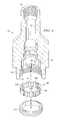
- FIG. 2is a perspective view of one exemplary embodiment of a locking swivel apparatus according to the present invention.
- FIG. 3is an exploded perspective view of a mandrel portion of the locking swivel apparatus of FIG. 2.
- FIG. 5is a cross-sectional view of the locking swivel apparatus of FIG. 2 in which the mandrel portion and the upper body portion are unlocked.
- FIG. 6is a cross-sectional view of the locking swivel apparatus of FIG. 2 in which the mandrel portion and the upper body portion are locked.
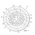
- FIG. 7is a cross sectional view as shown on section 7 - 7 of FIG. 6.
- FIG. 8is a cross sectional view of another exemplary embodiment of the present invention in which a mandrel portion and an upper body portion are unlocked.
- FIG. 9is a cross sectional representation of the locking swivel apparatus of FIG. 8 in which the mandrel portion and the upper body portion are locked.
- FIG. 10is a cross sectional representation of a portion of the locking swivel apparatus of FIG. 8 showing the engagement of a hideaway sleeve.
- FIG. 11is a cross sectional representation of a portion of yet another exemplary embodiment of the present invention showing the engagement of a hideaway sleeve.
- this inventionincludes an improved mechanical locking swivel having at least one replaceable gear.
- Embodiments of the locking swivel of this inventioninclude an upper body portion having a counter bore and a plurality of spaced apart teeth disposed on the counter bore wall that extend radially inward into the counter bore.
- a mandrelis slidably engaged within the counter bore of the upper body portion and typically includes a plurality of spaced apart teeth disposed on and extending radially outward from an outer surface thereof
- Embodiments of the locking swivel of this inventioninclude two replaceable gears, a first replaceable gear engaged with the teeth disposed on the upper body portion and a second replaceable gear engaged with the teeth disposed on the mandrel.
- the replaceable gearsmay also be selectively engaged and disengaged to one another, being engaged when the swivel is locked and disengaged when the swivel is unlocked.
- Embodiments of the locking swivel of this inventionmay include a supplemental locking mechanism for securing the swivel in the locked arrangement.
- Embodiments of the locking swivel of this inventionmay be coupleable to a drill string and useful in directional drilling, pipe recovery, wireline, and/or other oilfield applications.
- Exemplary embodiments of the present inventionadvantageously provide a mechanical locking swivel apparatus including replaceable gears for locking and unlocking the swivel.
- Swivels embodying this inventionmay thus be advantageous in that the gears may be replaced and/or exchanged, for example, when they have become excessively worn or damaged, thus providing potentially significant cost savings as compared to prior art swivels in which replacing entire body portions may be necessary.
- drill string 12includes an upper drive assembly 14 positioned above a multiple entry apparatus 16 , e.g., of the type disclosed in U.S. Pat. No. RE 33,150 to Boyd.
- the multiple entry apparatus 16may include a principal body portion 18 and an entry portion 20 offset from a longitudinal axis of the drill string 12 .
- Entry portion 20may include an upper fixture 22 for feeding a wireline 24 down through a bore in the drill string 12 , as illustrated.
- the swivel apparatus 10may be coupled to a section of drill pipe 25 that is mounted below the multiple entry apparatus.
- the swivel apparatus 10may further coupled to a section of drill pipe 26 , which may be moved into and out of the well bore at the level of the rotary table 28 .
- embodiments of the swivel apparatus of the present inventionare not limited to use with a multiple entry wireline apparatus, such as shown in FIG. 1.
- Embodiments of the swivel apparatusare equally well suited for substantially any application in which it is desirable to selectively rotate or lock a lower portion of a drill string with respect to an upper portion of the drill string.
- embodiments of the swivel apparatus of this inventionare not limited to use in oilfield applications, but may be used in substantially any application in which a locking swivel may be useful.
- locking swivel 10is typically a substantially cylindrical tool, being largely symmetrical about cylindrical axis 37 (also referred to herein as a longitudinal axis).
- Swivel 10includes a mandrel 40 , one end of which is slidably engaged with a counter bore (not shown in FIG. 2) of an upper end portion 32 , as described in more detail below with respect to FIGS. 3 through 6.
- a cap member 44threadably engaged with upper end portion 32 , prevents the mandrel 40 from disengaging from the upper end portion 32 .
- Cap member 44may optionally include one or more securing members 43 for securing the cap member 44 in place (e.g., a threaded hex bolt threadably engaged with a corresponding threaded bore hole tightened against the upper body portion 32 ).
- the mandrel 40 and upper end portion 32may include threaded end portions 41 and 30 , respectively, for coupling to the drill string.
- Mandrel 40 and upper end portion 32also typically include concentric through bores 34 and 35 , respectively (e.g., for permitting drilling fluid to flow therethrough or for permitting a wireline apparatus to move therethrough).
- FIG. 3an exploded perspective view of the mandrel 40 of the locking swivel 10 of FIG. 2 is illustrated.
- a lower end 39 of the mandrel 40typically includes a threaded pin end 41 , which is coupleable to a drill string.
- An upper end 38 of the mandrel 40includes a plurality of teeth 82 that define spaces 84 therebetween and extend radially outward from cylindrical axis 37 .
- the teeth 82are typically integral with the mandrel 40 , but may alternately be a portion of a separable component coupled thereto.
- the mandrel 40further includes a first replaceable gear 85 (e.g., a spur gear) having a plurality of teeth 86 along an inner surface 87 thereof, which are sized and shaped to engage teeth 82 .
- Gear 85further includes a plurality of spaced apart teeth 90 on an outer surface 92 thereof.
- the teeth 90 on the outer surface 92are sized and shaped to engage the teeth 104 on an inner surface of a second replaceable gear 98 , which in turn is engaged with the upper body portion 32 as described in more detail hereinbelow with respect to FIGS. 4 through 7.
- a threaded ring 89(or a suitable equivalent, such as a frictional fitting) engages a threaded portion 80 of upper end 38 and may be utilized to secure gear 85 in place, i.e., with the teeth 86 on the inner surface 87 thereof engaged with teeth 82 .
- the mandrel 40typically further includes flange 50 extending radially outward from the cylindrical axis 37 .
- mandrel 40may equivalently include an annular ring coupled thereto.
- FIG. 4an exploded, partially cutaway view of the upper body portion 32 of the locking swivel 10 of FIG. 2 is illustrated.
- one end of the upper body portion 32typically includes a threaded counter bore 30 for coupling to a drill string.
- the end opposite the threaded counter bore 30typically includes an enlarged counter bore 36 for receiving the mandrel 40 as shown in FIGS. 5 and 6.
- a plurality of teeth 96defining spaces 95 therebetween, protrudes radially inward from the inner wall 93 of the counter bore 36 .
- the teeth 96are typically integral with the inner wall 93 of the counter bore 36 , but may alternately be a portion of a replaceable component coupled thereto.
- the upper body portion 32typically includes a second replaceable gear 98 having a plurality of spaced apart teeth 100 on an outer surface 102 thereof, which are sized and shaped to engage teeth 96 .
- Gear 98also includes a plurality of spaced apart teeth 104 along an inner surface 105 thereof. The teeth 104 on the inner surface 105 of gear 98 are sized and shaped to engage the teeth 90 on the outer surface 92 of gear 85 as described above with respect to FIG. 3 and as described in more detail hereinbelow with respect to FIGS. 5 - 7 .
- a threaded ring 110engages a threaded portion 112 of counter bore 36 and may be utilized to hold gear 98 in place, i.e., with the teeth 100 on the outer surface 102 thereof engaged with teeth 96 .
- locking swivel 10includes a mandrel 40 , the upper end 38 of which is slidably engaged in an enlarged counter bore 36 of upper body portion 32 .
- the locking swivel 10further includes a lower cap member 44 threadably engaged with a threaded portion 42 of the upper body portion 32 .
- Threaded portion 42typically includes a left-hand thread (rather than the standard right-hand thread) to discourage the cap member 44 from becoming disengaged from the upper body portion 32 during operation of the locking swivel 10 .
- the use of a left-hand threadmay prevent the accidental loosening of the cap member 44 during the loosening of other threaded components (e.g., pin end 41 or threaded bore 30 ).
- the inner diameter of the lower opening 47 in cap member 44is less than the outer diameter of flange 50 .
- threading the cap member 44 to the upper body portion 32is intended to prevent the mandrel 40 from disengaging from within the enlarged counter bore 36 .
- Embodiments of the locking swivel apparatus 10 of this inventionmay, for example, include a recess 72 in the through bore 35 of the upper body portion for receiving one or more sealing assemblies. Suitable sealing assemblies include loaded lip seals such as a Polypack® seals, which are available from Gatlin Corporation (a distributor of Parker Seals), 661 St. Joseph Lane, Harvey, La. 70059.
- Embodiments of the locking swivel apparatusmay also include one or more blowholes, such as upper and lower blowholes 48 and 49 , for equalizing pressure in the counter bore 36 during locking and unlocking of the swivel 10 .
- locking swivel 10is shown unlocked, i.e., the upper body portion 32 and the mandrel 40 are decoupled, allowing relative rotation of the upper body portion and the mandrel about the cylindrical axis 37 .
- the upper body portion 32is moved in a downward direction 116 , along cylindrical axis 37 , with respect to the mandrel 40 , thus causing the upper end 38 of the mandrel 40 to penetrate deeper into the counter bore 36 of the upper body portion 32 , for example, until threaded ring 89 contacts the upper shoulder 91 of counter bore 36 .
- locking swivel 10is shown locked, i.e., the upper body portion 32 and the mandrel 40 are coupled, constraining the upper body portion 32 and the mandrel 40 to rotate together about the cylindrical axis 37 .
- upper body portion 32is moved in an upward direction 118 with respect to mandrel 40 , thus moving the upper end 38 of the mandrel 40 out of the counter bore 36 of the upper body portion 32 and towards cap member 44 , preferably until the lower side 51 of the flange 50 contacts the shoulder 45 of cap member 44 .
- this motionsubstantially corresponds to pulling mandrel 40 downwards out of counter bore 36 .
- the teeth 90 on the outer surface 92 of the first replaceable gear 85are engaged with the teeth 104 on the inner surface 105 of the second replaceable gear 98 .
- the mandrel 40is constrained to rotate with upper body portion 32 about cylindrical axis 37 .
- locking swivel 10may be coupled to a drill string, for example, as described above with respect to FIG. 1.
- the weight of the drill stringmay be allowed to rest on the rotary table, causing the upper body portion 32 to slide downward 116 (FIG. 5) relative to the mandrel 40 , thus disengaging outer teeth 90 of the first gear 85 from inner teeth 104 of the second gear 98 .
- the drill stringmay be lifted off the rotary table, causing the upper body portion 32 to slide upward 118 (FIG. 6) relative to the mandrel until teeth 90 are engaged with teeth 104 .
- swivel 10may also be unlocked by urging the mandrel 40 upwards relative to the upper body portion 32 and locked by urging the mandrel 40 downward relative to the upper body portion 32 .
- the pressure of such fluidsmay tend to hold such mechanisms in a locked state (since bringing the mandrel and upper body portion together to unlock the swivel may compress the fluid). In such situations, it will be seen that the pressure of such fluids in the swivel will need to be reduced to zero, or thereabouts, in order to unlock the swivel.
- replaceable gearssuch as replaceable gears 85 and 98 described above
- replacement of either or both of the mandrel or upper body portionis typically required at some point in the life of a swivel, usually at significant expense.
- the inner teeth 86 of first gear 90remain engaged with teeth 82 of the mandrel 40 .
- the outer teeth 100 of the second gear 98remain engaged with teeth 96 of the upper body portion 32 .
- the outer teeth 90 of the first gear 85engage and disengage, respectively, with the inner teeth 104 of the second gear 98 , which tends to limit wear and/or damage to the replaceable gears 85 and 98 .
- the replaceable gear, or gearsmay be removed and replaced.
- embodiments of the locking swivel 10 shown in FIGS. 2 - 7include two replaceable gears
- alternative embodiments of this inventionmay include any number of replaceable gears.
- embodiments of this inventionmay include a single replaceable gear having inner and outer teeth configured to engage teeth disposed on the mandrel and upper body portions, respectively.
- the single replaceable gearmay further be fabricated from a material having a hardness value less than that of the mandrel and upper body portions, thus substantially preventing wear and damage to the teeth that are integral with the mandrel and upper body portions.
- embodiments including a single replaceable gearmay be advantageous in that it simplifies, and thus tends to reduce the cost of fabrication.
- embodiments of this invention including three or more replaceable gearsmay be advantageous.
- Locking swivel 10 ′is similar to the locking swivel 10 illustrated in FIGS. 2 through 7, in that it includes a mandrel 40 ′, the upper end 38 ′ of which is slidably engaged in an enlarged counter bore 36 ′ of an upper body portion 32 ′.
- the locking swivel 10 ′further includes a lower cap member 44 ′ threadably engaged with the upper body portion 32 ′.
- Locking swivel 10 ′differs from locking swivel 10 in that when in the unlocked position (FIG.
- locking swivelmay also include a supplemental locking mechanism that prevents the locking swivel from accidentally unlocking.
- the supplemental locking mechanismis configured to prevent the mandrel from moving with respect to the upper body portion in a direction substantially parallel to the cylindrical axis, by interposing a substantially rigid member between a lower face of the upper body portion and a flange portion of the mandrel.
- the hideaway sleeves 120may further be coupleable (e.g., threaded) to corresponding pin members 122 that extend radially outward through the lower cap member 44 ′.
- An o-ring assembly 123may also be utilized to provided a frictional fitting between the pin members 122 and the cap member 44 ′ for preventing the sleeves 120 from inadvertently extending or retracting during use of the swivel 10 ′, e.g., via tool vibration.
- the hideaway sleeve(s) 120 shown in FIGS. 8 through 11are typically manually extended and retracted, it will be understood that they may alternatively and/or additionally be extended and retracted by a non-manual mechanism, such as a hydraulic or pneumatic piston.
- embodiments of the locking swivel including a supplementary locking mechanismmay include substantially any locking arrangement.
- embodiments of a locking swivel including a supplementary locking mechanismmay include a locking arrangement similar to that disclosed herein in which one or more replaceable gears selectively couple and decouple the upper body portion and the mandrel.
- Other embodiments of a locking swivel including a supplemental locking mechanismmay include a locking arrangement similar to that provided by the Boyd's commercially available locking swivel, described above in the background section.
- Locking swivel 10 ′′shown in FIG. 11, utilizes a similar locking arrangement in which teeth 82 ′′ of mandrel 40 ′′ engage teeth 96 ′′ of upper body portion 32 ′′ when the swivel 10 ′′ is locked.
- a locking swivel including a supplemental locking mechanismmay include a locking arrangement similar to that disclosed in U.S. Pat. No.
- the mandrelmay be positioned in the counter bore such that said selective engagement and disengagement of the first and second replaceable gears correspondingly couples and decouples the upper body portion and the mandrel, constraining and allowing relative rotation of the upper body portion and the mandrel about the cylindrical axis.
Landscapes
- Engineering & Computer Science (AREA)
- Life Sciences & Earth Sciences (AREA)
- Geology (AREA)
- Mining & Mineral Resources (AREA)
- Mechanical Engineering (AREA)
- Physics & Mathematics (AREA)
- Environmental & Geological Engineering (AREA)
- Fluid Mechanics (AREA)
- General Life Sciences & Earth Sciences (AREA)
- Geochemistry & Mineralogy (AREA)
- Earth Drilling (AREA)
- Protection Of Pipes Against Damage, Friction, And Corrosion (AREA)
Abstract
Description
- Locking swivel devices are well known in the mechanical arts and are used in a wide variety of applications, such as medical device, sporting good, motor vehicle, and drilling applications. For example, during well drilling operations, a conventional locking swivel apparatus may be coupled to a drill string at the surface of the well (e.g., above the rotary table) with a portion of the drill string extending from the locking swivel downhole into the well bore. Locking the swivel couples the portion of the drill string disposed below the swivel to that disposed above (e.g., a side entry wire apparatus and/or an upper drive assembly), constraining them to rotate together about a longitudinal (usually cylindrical) axis. Unlocking the swivel allows the portion of the drill string disposed below the swivel to rotate about the longitudinal axis with respect to the portion disposed above the swivel.[0001]
- U.S. Pat. No. 5,996,712 to Boyd discloses a Mechanical Locking Swivel Apparatus including an upper body portion having a counter bore for receiving the upper end of a mandrel, the mandrel being able to move within the counter bore. The upper end of the mandrel also includes a plurality of outwardly extending teeth. The upper body portion includes one or more pin members that extend into the counter bore and engage the teeth, thus locking the mandrel in place with respect to the upper body portion. The mandrel may be moved longitudinally in the counter bore thus disengaging the teeth from the pin members and allowing the mandrel to rotate freely about its longitudinal axis with respect to the upper body portion.[0002]
- A mechanical locking swivel is also currently commercially available from Boyd's Rental Tools of New Iberia, La., and is the subject of co-pending U.S. patent application Ser. No. 09/498,188. In this commercially available tool, the upper body portion includes a plurality of teeth extending inward into the counter bore (rather than the pin members disclosed in the '712 patent). The teeth on the upper body portion slideably engage the teeth on the mandrel when the mandrel and upper body portion are pulled apart, thus locking the mandrel in place with the upper body portion. As described above with respect to the '712 patent, the mandrel may also be moved longitudinally in the counter bore towards the upper body portion, thus slideably disengaging the interlocking teeth and allowing the mandrel to rotate freely about its longitudinal axis with respect to the upper body portion.[0003]
- While Boyd's commercially available locking swivel described above has shown itself to be highly serviceable, it is natural that repeated locking and unlocking (i.e., engaging and disengaging of the teeth disposed on the upper body portion and the mandrel) tends to cause wear and/or damage to the teeth. In time, if the teeth become sufficiently worn and/or damaged, replacement of either or both the mandrel and upper body portion is typically required at significant expense. It has also been found that there is a possibility for locking swivel apparatuses to unlock while being coupled to a drill string, thus increasing the difficulty of the coupling procedure. Therefore, there exists a need for a yet further improved locking swivel apparatus.[0004]
- In one aspect the present invention includes a locking swivel apparatus. The apparatus includes an upper body portion having a counter bore about a cylindrical axis, a mandrel receivable in the counter bore, and a lower cap member threadably engaged with the upper body portion. The apparatus further includes an internal locking arrangement configured to selectively couple and decouple the upper body portion and the mandrel. The selective coupling and decoupling are disposed to correspondingly constrain and allow relative rotation of the upper body portion and the mandrel about the cylindrical axis. The apparatus still further includes a supplemental internal locking mechanism configured, upon engagement, to selectively constrain the upper body portion and the mandrel from reciprocating along the cylindrical axis. Engagement of the supplemental locking mechanism is operable to secure the upper body portion and the mandrel in the coupled position. Methods are provided for fabricating and retrofitting embodiments of the present invention. In certain other embodiments the locking arrangement may include one or more replaceable gear members.[0005]
- In one variation of this aspect, the locking arrangement includes first and second gear members engageable with one another, the first gear member is engaged with a plurality of teeth disposed on the mandrel and the second gear member is engaged with a plurality of teeth disposed in the counter bore.[0006]
- In another variation of this aspect, the upper body portion has a lower face confronting a flange portion provided on the mandrel. The supplemental internal locking mechanism includes at least one selectively extendable and retractable sleeve. Extending the at least one sleeve interposes it between the lower face and the flange and is operable to secure the upper body portion and the mandrel in a coupled position. Retracting the at least one sleeve is operable to allow the upper body portion and the mandrel to reciprocate along the cylindrical axis, allowing the upper body portion and the mandrel to be selectively coupled and decoupled. The lower cap member includes at least one internal recess into which the at least one sleeve may be retracted.[0007]
- In another aspect this invention includes a method for securing a locking swivel apparatus in a locked arrangement. The method includes providing a locking swivel apparatus such as described in the preceding paragraphs, operating the locking arrangement to engage the upper body portion and the mandrel in a coupled position, and extending the at least one sleeve between the lower face and the flange to secure the upper body portion and the mandrel in the coupled position.[0008]
- It is therefore a technical advantage of the present invention to provide a locking swivel apparatus including a supplemental locking mechanism. Such a feature is useful, for example, to prevent accidental decoupling of the locking arrangement.[0009]
- The foregoing has outlined rather broadly the features and technical advantages of the present invention in order that the detailed description of the invention that follows may be better understood. Additional features and advantages of the invention will be described hereinafter, which form the subject of the claims of the invention. It should be appreciated by those skilled in the art that the conception and the specific embodiment disclosed may be readily utilized as a basis for modifying or designing other structures for carrying out the same purposes of the present invention. It should be also be realize by those skilled in the art that such equivalent constructions do not depart from the spirit and scope of the invention as set forth in the appended claims.[0010]
- For a more complete understanding of the present invention, and the advantages thereof, reference is now made to the following descriptions taken in conjunction with the accompanying drawings, in which:[0011]
- FIG. 1 is a schematic illustration of a drill string utilizing a locking swivel apparatus according to one exemplary embodiment of the present invention.[0012]
- FIG. 2 is a perspective view of one exemplary embodiment of a locking swivel apparatus according to the present invention.[0013]
- FIG. 3 is an exploded perspective view of a mandrel portion of the locking swivel apparatus of FIG. 2.[0014]
- FIG. 4 is an exploded perspective view of an upper body portion of the locking swivel apparatus of FIG. 2.[0015]
- FIG. 5 is a cross-sectional view of the locking swivel apparatus of FIG. 2 in which the mandrel portion and the upper body portion are unlocked.[0016]
- FIG. 6 is a cross-sectional view of the locking swivel apparatus of FIG. 2 in which the mandrel portion and the upper body portion are locked.[0017]
- FIG. 7 is a cross sectional view as shown on section[0018]7-7 of FIG. 6.
- FIG. 8 is a cross sectional view of another exemplary embodiment of the present invention in which a mandrel portion and an upper body portion are unlocked.[0019]
- FIG. 9 is a cross sectional representation of the locking swivel apparatus of FIG. 8 in which the mandrel portion and the upper body portion are locked.[0020]
- FIG. 10 is a cross sectional representation of a portion of the locking swivel apparatus of FIG. 8 showing the engagement of a hideaway sleeve.[0021]
- FIG. 11 is a cross sectional representation of a portion of yet another exemplary embodiment of the present invention showing the engagement of a hideaway sleeve.[0022]
- Referring briefly to the accompanying figures, this invention includes an improved mechanical locking swivel having at least one replaceable gear. Embodiments of the locking swivel of this invention include an upper body portion having a counter bore and a plurality of spaced apart teeth disposed on the counter bore wall that extend radially inward into the counter bore. A mandrel is slidably engaged within the counter bore of the upper body portion and typically includes a plurality of spaced apart teeth disposed on and extending radially outward from an outer surface thereof Embodiments of the locking swivel of this invention include two replaceable gears, a first replaceable gear engaged with the teeth disposed on the upper body portion and a second replaceable gear engaged with the teeth disposed on the mandrel. The replaceable gears may also be selectively engaged and disengaged to one another, being engaged when the swivel is locked and disengaged when the swivel is unlocked. Embodiments of the locking swivel of this invention may include a supplemental locking mechanism for securing the swivel in the locked arrangement. Embodiments of the locking swivel of this invention may be coupleable to a drill string and useful in directional drilling, pipe recovery, wireline, and/or other oilfield applications.[0023]
- Exemplary embodiments of the present invention advantageously provide a mechanical locking swivel apparatus including replaceable gears for locking and unlocking the swivel. Swivels embodying this invention may thus be advantageous in that the gears may be replaced and/or exchanged, for example, when they have become excessively worn or damaged, thus providing potentially significant cost savings as compared to prior art swivels in which replacing entire body portions may be necessary. These and other advantages of this invention will become evident in light of the following discussion of various embodiments thereof.[0024]
- Referring now to FIG. 1, one embodiment of a locking[0025]
swivel 10 of this invention is schematically illustrated in use in a drill string generally denoted as12. In the exemplary embodiment shown,drill string 12 includes anupper drive assembly 14 positioned above amultiple entry apparatus 16, e.g., of the type disclosed in U.S. Pat. No. RE 33,150 to Boyd. Themultiple entry apparatus 16 may include aprincipal body portion 18 and anentry portion 20 offset from a longitudinal axis of thedrill string 12.Entry portion 20 may include anupper fixture 22 for feeding awireline 24 down through a bore in thedrill string 12, as illustrated. Theswivel apparatus 10 may be coupled to a section ofdrill pipe 25 that is mounted below the multiple entry apparatus. Theswivel apparatus 10 may further coupled to a section ofdrill pipe 26, which may be moved into and out of the well bore at the level of the rotary table28. - It will be understood by those of ordinary skill in the art that embodiments of the swivel apparatus of the present invention are not limited to use with a multiple entry wireline apparatus, such as shown in FIG. 1. Embodiments of the swivel apparatus are equally well suited for substantially any application in which it is desirable to selectively rotate or lock a lower portion of a drill string with respect to an upper portion of the drill string. It will be further understood by those of ordinary skill in the art that embodiments of the swivel apparatus of this invention are not limited to use in oilfield applications, but may be used in substantially any application in which a locking swivel may be useful.[0026]
- Referring now to FIG. 2, one exemplary embodiment of a locking[0027]
swivel 10 according to present invention is illustrated in perspective view. In FIG. 2, lockingswivel 10 is typically a substantially cylindrical tool, being largely symmetrical about cylindrical axis37 (also referred to herein as a longitudinal axis).Swivel 10 includes amandrel 40, one end of which is slidably engaged with a counter bore (not shown in FIG. 2) of anupper end portion 32, as described in more detail below with respect to FIGS. 3 through 6. Acap member 44, threadably engaged withupper end portion 32, prevents themandrel 40 from disengaging from theupper end portion 32.Cap member 44 may optionally include one ormore securing members 43 for securing thecap member 44 in place (e.g., a threaded hex bolt threadably engaged with a corresponding threaded bore hole tightened against the upper body portion32). In embodiments in which theswivel 10 is coupled to a drill string (e.g.,drill string 12 in FIG. 1), themandrel 40 andupper end portion 32 may include threadedend portions Mandrel 40 andupper end portion 32 also typically include concentric throughbores - Referring now to FIG. 3, an exploded perspective view of the[0028]
mandrel 40 of the lockingswivel 10 of FIG. 2 is illustrated. As described above with respect to FIG. 2, alower end 39 of themandrel 40 typically includes a threadedpin end 41, which is coupleable to a drill string. Anupper end 38 of themandrel 40 includes a plurality ofteeth 82 that definespaces 84 therebetween and extend radially outward fromcylindrical axis 37. Theteeth 82 are typically integral with themandrel 40, but may alternately be a portion of a separable component coupled thereto. Themandrel 40 further includes a first replaceable gear85 (e.g., a spur gear) having a plurality ofteeth 86 along aninner surface 87 thereof, which are sized and shaped to engageteeth 82.Gear 85 further includes a plurality of spaced apartteeth 90 on anouter surface 92 thereof. Theteeth 90 on theouter surface 92 are sized and shaped to engage theteeth 104 on an inner surface of a secondreplaceable gear 98, which in turn is engaged with theupper body portion 32 as described in more detail hereinbelow with respect to FIGS. 4 through 7. A threaded ring89 (or a suitable equivalent, such as a frictional fitting) engages a threadedportion 80 ofupper end 38 and may be utilized to securegear 85 in place, i.e., with theteeth 86 on theinner surface 87 thereof engaged withteeth 82. Themandrel 40 typically further includesflange 50 extending radially outward from thecylindrical axis 37. The artisan of ordinary skill will readily recognize thatmandrel 40 may equivalently include an annular ring coupled thereto. - Referring now to FIG. 4, an exploded, partially cutaway view of the[0029]
upper body portion 32 of the lockingswivel 10 of FIG. 2 is illustrated. As described above with respect to FIG. 2, one end of theupper body portion 32 typically includes a threaded counter bore30 for coupling to a drill string. The end opposite the threaded counter bore30 typically includes an enlarged counter bore36 for receiving themandrel 40 as shown in FIGS. 5 and 6. A plurality ofteeth 96, definingspaces 95 therebetween, protrudes radially inward from theinner wall 93 of the counter bore36. Theteeth 96 are typically integral with theinner wall 93 of the counter bore36, but may alternately be a portion of a replaceable component coupled thereto. Theupper body portion 32 typically includes a secondreplaceable gear 98 having a plurality of spaced apartteeth 100 on anouter surface 102 thereof, which are sized and shaped to engageteeth 96.Gear 98 also includes a plurality of spaced apartteeth 104 along aninner surface 105 thereof. Theteeth 104 on theinner surface 105 ofgear 98 are sized and shaped to engage theteeth 90 on theouter surface 92 ofgear 85 as described above with respect to FIG. 3 and as described in more detail hereinbelow with respect to FIGS.5-7. A threaded ring110 (or a suitable equivalent) engages a threadedportion 112 of counter bore36 and may be utilized to holdgear 98 in place, i.e., with theteeth 100 on theouter surface 102 thereof engaged withteeth 96. - Referring now to FIGS. 5 and 6, cross sectional schematic representations of a portion of the locking[0030]
swivel 10 of FIG. 2 are illustrated. As described above with respect to FIGS. 2 through 4, lockingswivel 10 includes amandrel 40, theupper end 38 of which is slidably engaged in an enlarged counter bore36 ofupper body portion 32. The lockingswivel 10 further includes alower cap member 44 threadably engaged with a threadedportion 42 of theupper body portion 32. Threadedportion 42 typically includes a left-hand thread (rather than the standard right-hand thread) to discourage thecap member 44 from becoming disengaged from theupper body portion 32 during operation of the lockingswivel 10. For example, the use of a left-hand thread may prevent the accidental loosening of thecap member 44 during the loosening of other threaded components (e.g., pinend 41 or threaded bore30). The inner diameter of thelower opening 47 incap member 44 is less than the outer diameter offlange 50. Thus threading thecap member 44 to theupper body portion 32 is intended to prevent themandrel 40 from disengaging from within the enlarged counter bore36. - For some applications, such as oil field applications in which a drilling fluid flows through the swivel apparatus, it may be desirable to provide a seal between the[0031]
upper body portion 32 and theupper end 38 of themandrel 40, for example to inhibit drilling fluid from penetrating the counter bore36. Embodiments of the lockingswivel apparatus 10 of this invention may, for example, include arecess 72 in the throughbore 35 of the upper body portion for receiving one or more sealing assemblies. Suitable sealing assemblies include loaded lip seals such as a Polypack® seals, which are available from Gatlin Corporation (a distributor of Parker Seals), 661 St. Joseph Lane, Harvey, La. 70059. Embodiments of the locking swivel apparatus may also include one or more blowholes, such as upper andlower blowholes swivel 10. - With further reference to FIG. 5, locking[0032]
swivel 10 is shown unlocked, i.e., theupper body portion 32 and themandrel 40 are decoupled, allowing relative rotation of the upper body portion and the mandrel about thecylindrical axis 37. In order to unlock theswivel 10, theupper body portion 32 is moved in adownward direction 116, alongcylindrical axis 37, with respect to themandrel 40, thus causing theupper end 38 of themandrel 40 to penetrate deeper into the counter bore36 of theupper body portion 32, for example, until threadedring 89 contacts theupper shoulder 91 of counter bore36. The artisan of ordinary skill will readily recognize that this is analogous to pushingmandrel 40 upwards into counter bore36 of theupper body portion 32. Movingupper body portion 32 downward will be seen to cause theteeth 90 on the outer surface92 (FIG. 3) of the firstreplaceable gear 85 to become disengaged with theteeth 104 on the inner surface105 (FIG. 4) of the secondreplaceable gear 98. Thus, as described above, themandrel 40 is substantially free to rotate in counter bore36 aboutcylindrical axis 37 with respect toupper body portion 32. - Referring now to FIGS. 6 and 7, locking[0033]
swivel 10 is shown locked, i.e., theupper body portion 32 and themandrel 40 are coupled, constraining theupper body portion 32 and themandrel 40 to rotate together about thecylindrical axis 37. In order to lock theswivel 10,upper body portion 32 is moved in anupward direction 118 with respect tomandrel 40, thus moving theupper end 38 of themandrel 40 out of the counter bore36 of theupper body portion 32 and towardscap member 44, preferably until thelower side 51 of theflange 50 contacts theshoulder 45 ofcap member 44. The artisan of ordinary skill will readily recognize that this motion substantially corresponds to pullingmandrel 40 downwards out of counter bore36. Theteeth 90 on theouter surface 92 of the firstreplaceable gear 85 are engaged with theteeth 104 on theinner surface 105 of the secondreplaceable gear 98. Thus, as described above, themandrel 40 is constrained to rotate withupper body portion 32 aboutcylindrical axis 37. - In operation, locking[0034]
swivel 10 may be coupled to a drill string, for example, as described above with respect to FIG. 1. In order to unlock theswivel 10 the weight of the drill string may be allowed to rest on the rotary table, causing theupper body portion 32 to slide downward116 (FIG. 5) relative to themandrel 40, thus disengagingouter teeth 90 of thefirst gear 85 frominner teeth 104 of thesecond gear 98. In order to lock theswivel 10, the drill string may be lifted off the rotary table, causing theupper body portion 32 to slide upward118 (FIG. 6) relative to the mandrel untilteeth 90 are engaged withteeth 104. The artisan of ordinary skill will readily recognize thatswivel 10 may also be unlocked by urging themandrel 40 upwards relative to theupper body portion 32 and locked by urging themandrel 40 downward relative to theupper body portion 32. The artisan of ordinary skill will further recognize that in embodiments of the invention where locking and unlocking mechanisms are exposed to downhole fluids such as drilling fluid, the pressure of such fluids may tend to hold such mechanisms in a locked state (since bringing the mandrel and upper body portion together to unlock the swivel may compress the fluid). In such situations, it will be seen that the pressure of such fluids in the swivel will need to be reduced to zero, or thereabouts, in order to unlock the swivel. - As described hereinabove, the use of one or more replaceable gears (such as[0035]
replaceable gears swivel 10, however, theinner teeth 86 offirst gear 90 remain engaged withteeth 82 of themandrel 40. Likewise, theouter teeth 100 of thesecond gear 98 remain engaged withteeth 96 of theupper body portion 32. During locking and unlocking theouter teeth 90 of thefirst gear 85 engage and disengage, respectively, with theinner teeth 104 of thesecond gear 98, which tends to limit wear and/or damage to thereplaceable gears - While the embodiments of the locking[0036]
swivel 10 shown in FIGS.2-7 include two replaceable gears, it will be appreciated that alternative embodiments of this invention may include any number of replaceable gears. For example, embodiments of this invention may include a single replaceable gear having inner and outer teeth configured to engage teeth disposed on the mandrel and upper body portions, respectively. The single replaceable gear may further be fabricated from a material having a hardness value less than that of the mandrel and upper body portions, thus substantially preventing wear and damage to the teeth that are integral with the mandrel and upper body portions. For some applications, embodiments including a single replaceable gear may be advantageous in that it simplifies, and thus tends to reduce the cost of fabrication. Alternatively, in other applications, embodiments of this invention including three or more replaceable gears may be advantageous. - Referring now to FIGS. 8 and 9, further alternate embodiments of this invention are illustrated. Locking[0037]
swivel 10′ is similar to the lockingswivel 10 illustrated in FIGS. 2 through 7, in that it includes amandrel 40′, theupper end 38′ of which is slidably engaged in an enlarged counter bore36′ of anupper body portion 32′. The lockingswivel 10′ further includes alower cap member 44′ threadably engaged with theupper body portion 32′. Lockingswivel 10′ differs from lockingswivel 10 in that when in the unlocked position (FIG. 8) anupper face 52 offlange 50 contacts alower face 131 of theupper body portion 32′ (rather than threadedring 89 contactingshoulder 91 as shown in FIG. 5).Swivel 10′ further includes anoptional indicator ring 140 that provides a quick visual indication to an operator of whether the swivel is locked or unlocked. When theswivel 10′ is unlocked, theindicator ring 140 is positioned substantially adjacent to capmember 44′ as shown in FIG. 8. When theswivel 10′ is locked, agap 142 is present betweenindicator ring 140 andcap member 44′ as shown in FIG. 9. - Referring now also to FIGS. 10 and 11, other embodiments of locking swivel according to the present invention may also include a supplemental locking mechanism that prevents the locking swivel from accidentally unlocking. The supplemental locking mechanism is configured to prevent the mandrel from moving with respect to the upper body portion in a direction substantially parallel to the cylindrical axis, by interposing a substantially rigid member between a lower face of the upper body portion and a flange portion of the mandrel.[0038]
- In the embodiments shown in FIGS. 8 through 11, the supplemental locking mechanism includes one or more[0039]
hideaway sleeves 120 that are extendable radially inward fromcap member 44′ and thus may be interposed between thelower face 131 of theupper body portion 32′ and theupper face 52 offlange 50. Extension ofhideaway sleeves 120 preventupper body portion 32′ from moving downward relative to mandrel40′ and thus prevent theswivel 10′ from unlocking. In order to unlock theswivel 10′, thehideaway sleeves 120 are retractable intohideaway recesses 124 in thecap member 44′, thus allowing theupper body portion 32′ to slide downward relative to mandrel40 untillower face 131 contactsupper face 52 offlange 50. Thehideaway sleeves 120 may further be coupleable (e.g., threaded) to correspondingpin members 122 that extend radially outward through thelower cap member 44′. An o-ring assembly 123, or suitable equivalent, may also be utilized to provided a frictional fitting between thepin members 122 and thecap member 44′ for preventing thesleeves 120 from inadvertently extending or retracting during use of theswivel 10′, e.g., via tool vibration. While the hideaway sleeve(s)120 shown in FIGS. 8 through 11 are typically manually extended and retracted, it will be understood that they may alternatively and/or additionally be extended and retracted by a non-manual mechanism, such as a hydraulic or pneumatic piston. - The use of a supplemental locking mechanism, such as that shown in FIGS. 8 through 11, may be advantageous for some applications. For example, in oil field applications in which the swivel is coupled to a drill string, it is common practice to allow at least a portion of the weight of the swivel to rest on the section of drill pipe to which the mandrel is to be coupled. As a result, there is possibility that the upper body portion may accidentally slide downward relative to the mandrel and thus unlock the swivel (e.g., disengage gears[0040]85 and98 in embodiment10), which may make it more difficult to thread the mandrel to the drill string. The use of a supplemental locking mechanism, however, such as, for example, the
hideaway sleeves 120 coupled to pinmembers 122, prevents theswivel 10′ from unlocking under its own weight and thus, in the exemplary use of a locking swivel in a drill string, may simplify the coupling procedure with the drill string. - The artisan of ordinary skill will readily recognize that embodiments of the locking swivel including a supplementary locking mechanism may include substantially any locking arrangement. For example, embodiments of a locking swivel including a supplementary locking mechanism may include a locking arrangement similar to that disclosed herein in which one or more replaceable gears selectively couple and decouple the upper body portion and the mandrel. Other embodiments of a locking swivel including a supplemental locking mechanism may include a locking arrangement similar to that provided by the Boyd's commercially available locking swivel, described above in the background section. In such commercially available tools, a plurality of teeth disposed on an outer surface of the mandrel are engageable with a plurality of teeth disposed in the counter bore of the upper body portion. Locking[0041]
swivel 10″, shown in FIG. 11, utilizes a similar locking arrangement in whichteeth 82″ ofmandrel 40″ engageteeth 96″ ofupper body portion 32″ when theswivel 10″ is locked. Yet other embodiments of a locking swivel including a supplemental locking mechanism may include a locking arrangement similar to that disclosed in U.S. Pat. No. 6,244,345 in which a plurality of teeth (i.e., spline) disposed on an outer surface of an internal locking mandrel engage a plurality of teeth disposed on the inner surfaces of a swivel mandrel and/or a lower body portion. Still other embodiments of a locking swivel including a supplemental locking mechanism may include a locking arrangement similar to that disclosed in U.S. Pat. No. 5,996,712 in which one or more pin members extend through the upper body portion and selectively engage and disengage with a plurality of teeth disposed on an outer surface of the mandrel. - The artisan of ordinary skill will readily appreciate that although the embodiments as illustrated and described depict a device that is manually coupled and decoupled to correspondingly lock and unlock the locking swivel apparatus, other embodiments not illustrated will be within the scope of this invention that may include power assistance for coupling and decoupling. For example, such power assistance may include hydraulic or pneumatic actuation.[0042]
- The embodiments of the swivel apparatus described herein are typically fabricated from metal forgings or metal stock using conventional fabrication techniques (e.g., machining). The artisan of ordinary skill will readily recognize that embodiments of the locking swivel apparatus may also be fabricated by converting substantially any swivel apparatus having an upper body portion with a counter bore and a mandrel receivable in the counter bore into a locking swivel apparatus with replaceable gear members. Such retrofitting will be appreciated to be available, for example, on non-locking swivels, or on locking swivels whose teeth have become worn or damaged. For example, in a non-locking swivel, a plurality of teeth may be formed in the upper body portion, extending into the counter bore thereof and a plurality of teeth may be formed in the mandrel, extending outward from an outer surface thereof. A first replaceable gear may be disposed in engagement with the teeth of the mandrel and a second replaceable gear may be disposed in engagement with the teeth of the upper body portion such that the first and second replaceable gears are selectively engageable and disengageable with one another. The mandrel may be positioned in the counter bore such that said selective engagement and disengagement of the first and second replaceable gears correspondingly couples and decouples the upper body portion and the mandrel, constraining and allowing relative rotation of the upper body portion and the mandrel about the cylindrical axis.[0043]
- Alternatively, the artisan of ordinary skill will appreciate that existing locking swivel devices with worn or damaged teeth may also be retrofitted with replaceable gear members. The worn or damaged teeth in the upper body and mandrel may be formed or shaped to receive replaceable gear members such that the gear members are selectively engageable and disengageable with one another as the mandrel and upper body are reciprocated parallel to the cylindrical axis.[0044]
- Although the present invention and its advantages have been described in detail, it should be understood that various changes, substitutions and alternations can be made herein without departing from the spirit and scope of the invention as defined by the appended claims.[0045]
Claims (52)
Priority Applications (2)
| Application Number | Priority Date | Filing Date | Title |
|---|---|---|---|
| US10/352,847US6915865B2 (en) | 2003-01-28 | 2003-01-28 | Locking swivel apparatus with a supplemental internal locking mechanism |
| CA002456020ACA2456020C (en) | 2003-01-28 | 2004-01-27 | Locking swivel apparatus with a supplemental internal locking mechanism |
Applications Claiming Priority (1)
| Application Number | Priority Date | Filing Date | Title |
|---|---|---|---|
| US10/352,847US6915865B2 (en) | 2003-01-28 | 2003-01-28 | Locking swivel apparatus with a supplemental internal locking mechanism |
Publications (2)
| Publication Number | Publication Date |
|---|---|
| US20040144571A1true US20040144571A1 (en) | 2004-07-29 |
| US6915865B2 US6915865B2 (en) | 2005-07-12 |
Family
ID=32736077
Family Applications (1)
| Application Number | Title | Priority Date | Filing Date |
|---|---|---|---|
| US10/352,847Expired - LifetimeUS6915865B2 (en) | 2003-01-28 | 2003-01-28 | Locking swivel apparatus with a supplemental internal locking mechanism |
Country Status (2)
| Country | Link |
|---|---|
| US (1) | US6915865B2 (en) |
| CA (1) | CA2456020C (en) |
Cited By (7)
| Publication number | Priority date | Publication date | Assignee | Title |
|---|---|---|---|---|
| WO2013130977A3 (en)* | 2012-03-01 | 2014-04-17 | Saudi Arabian Oil Company | A continuous rotary drilling system and method of use |
| WO2014087117A1 (en)* | 2012-12-04 | 2014-06-12 | National Oilwell Varco, L.P. | Lockable swivel apparatus |
| US20140318809A1 (en)* | 2011-12-30 | 2014-10-30 | National Oilwell Varco Uk Limited | Connector device for use in wireline intervention operations |
| US20150330156A1 (en)* | 2014-05-16 | 2015-11-19 | Weatherford/Lamb, Inc. | Swivel |
| US20160160576A1 (en)* | 2014-12-05 | 2016-06-09 | Premium Artificial Lift Systems Ltd. | Downhole tubing swivels and related methods |
| WO2022186822A1 (en)* | 2021-03-01 | 2022-09-09 | Halliburton Energy Services, Inc. | Dual clutch system for travel joint |
| US20230008314A1 (en)* | 2019-12-12 | 2023-01-12 | Sven Beckhusen | Apparatus for connecting a drill pipe to the drilling drive of a drilling rig, and drilling assembly for boreholes comprising such an apparatus |
Families Citing this family (7)
| Publication number | Priority date | Publication date | Assignee | Title |
|---|---|---|---|---|
| GB0507639D0 (en) | 2005-04-15 | 2005-05-25 | Caledus Ltd | Downhole swivel sub |
| AU2012261541B2 (en)* | 2006-05-08 | 2015-05-28 | Mako Rentals, Inc. | Downhole swivel apparatus and method |
| US8627890B2 (en)* | 2007-07-27 | 2014-01-14 | Weatherford/Lamb, Inc. | Rotating continuous flow sub |
| US8171991B2 (en)* | 2008-08-07 | 2012-05-08 | Anthony Ray Boyd | Drillstring swivel torque monitor |
| US9033052B2 (en)* | 2010-09-20 | 2015-05-19 | Mako Rentals, Inc. | Rotating and reciprocating swivel apparatus and method |
| US8292150B2 (en) | 2010-11-02 | 2012-10-23 | Tyco Healthcare Group Lp | Adapter for powered surgical devices |
| WO2021097011A1 (en)* | 2019-11-14 | 2021-05-20 | Schlumberger Technology Corporation | Torque transfer system |
Citations (49)
| Publication number | Priority date | Publication date | Assignee | Title |
|---|---|---|---|---|
| US1723934A (en)* | 1925-12-28 | 1929-08-06 | Alfred G Heggem | Casing head |
| US2016042A (en)* | 1933-09-13 | 1935-10-01 | Miles J Lewis | Well bore deflecting tool |
| US2100418A (en)* | 1937-06-12 | 1937-11-30 | Shell Dev | Orienting device for borehole deflecting tools |
| US3762725A (en)* | 1971-05-20 | 1973-10-02 | Otis Eng Corp | Wireline stuffing box and sheave |
| US3948588A (en)* | 1973-08-29 | 1976-04-06 | Bakerdrill, Inc. | Swivel for core drilling |
| US4051456A (en)* | 1975-12-08 | 1977-09-27 | Exxon Production Research Company | Apparatus for establishing and maintaining electric continuity in drill pipe |
| US4062551A (en)* | 1975-12-05 | 1977-12-13 | Jim Base | Cable seal unit for earth-boring drill strings |
| US4064953A (en)* | 1976-06-22 | 1977-12-27 | Gulf Oil Corporation | Shear sub for drill string |
| US4074775A (en)* | 1975-02-25 | 1978-02-21 | Fishing Tools, Inc. | Power swivel |
| US4106575A (en)* | 1976-07-12 | 1978-08-15 | Fmc Corporation | Tool string and means for supporting and rotating the same |
| US4200297A (en)* | 1976-09-13 | 1980-04-29 | Sperry-Sun, Inc. | Side entry clamp and packoff |
| US4226447A (en)* | 1976-01-09 | 1980-10-07 | Brown Oil Tools, Inc. | Swivel apparatus |
| US4256179A (en)* | 1979-10-15 | 1981-03-17 | International Oil Tools, Inc. | Indexing tool for use in earth borehole drilling and testing |
| US4333530A (en)* | 1976-08-16 | 1982-06-08 | Armstrong Ernest E | Method and apparatus for cementing a casing |
| US4388969A (en)* | 1980-12-01 | 1983-06-21 | Nl Industries, Inc. | Borehole pipe side entry method and apparatus |
| US4399877A (en)* | 1981-04-17 | 1983-08-23 | Nl Sperry Sun, Inc. | Continuous borehole telemetry system and method |
| US4401170A (en)* | 1979-09-24 | 1983-08-30 | Reading & Bates Construction Co. | Apparatus for drilling underground arcuate paths and installing production casings, conduits, or flow pipes therein |
| US4449596A (en)* | 1982-08-03 | 1984-05-22 | Varco International, Inc. | Drilling of wells with top drive unit |
| US4470469A (en)* | 1980-04-01 | 1984-09-11 | Slurry Mining Engrg. Inc. | Swivel head for drilling and mining tool |
| US4506729A (en)* | 1983-02-22 | 1985-03-26 | Exxon Production Research Co. | Drill string sub with self closing cable port valve |
| US4524834A (en)* | 1982-06-22 | 1985-06-25 | Smith International, Inc. | Cablehead side entry sub |
| US4572305A (en)* | 1983-01-27 | 1986-02-25 | George Swietlik | Drilling apparatus |
| US4575359A (en)* | 1984-05-02 | 1986-03-11 | Bermingham Construction Limited | Rotary drive coupling |
| US4613002A (en)* | 1984-04-30 | 1986-09-23 | Hughes Tool Company | Downhole drilling tool with improved swivel |
| US4619326A (en)* | 1985-04-19 | 1986-10-28 | Shell California Production Inc. | Liner hanger with brass packer |
| US4681162A (en)* | 1986-02-19 | 1987-07-21 | Boyd's Bit Service, Inc. | Borehole drill pipe continuous side entry or exit apparatus and method |
| US4813493A (en)* | 1987-04-14 | 1989-03-21 | Triten Corporation | Hydraulic top drive for wells |
| US4821814A (en)* | 1987-04-02 | 1989-04-18 | 501 W-N Apache Corporation | Top head drive assembly for earth drilling machine and components thereof |
| US4984641A (en)* | 1990-02-07 | 1991-01-15 | Pryor Dale H | Swivels |
| US5086844A (en)* | 1989-10-10 | 1992-02-11 | Union Oil Company Of California | Hydraulic release oil tool |
| US5117927A (en)* | 1991-02-01 | 1992-06-02 | Anadrill | Downhole adjustable bent assemblies |
| US5168943A (en)* | 1991-06-24 | 1992-12-08 | Falgout Sr Thomas E | Adjustable bent sub |
| US5284210A (en)* | 1993-02-04 | 1994-02-08 | Helms Charles M | Top entry sub arrangement |
| US5314032A (en)* | 1993-05-17 | 1994-05-24 | Camco International Inc. | Movable joint bent sub |
| US5351767A (en)* | 1991-11-07 | 1994-10-04 | Globral Marine Inc. | Drill pipe handling |
| US5368111A (en)* | 1993-06-16 | 1994-11-29 | Benoit; Lloyd F. | Directional drilling sub with improved multi-slot locking arrangement |
| US5373906A (en)* | 1993-03-08 | 1994-12-20 | Braddick; Britt O. | Orientable guide assembly and method of use |
| US5396952A (en)* | 1993-10-20 | 1995-03-14 | Stogner; Huey | Drilling rig kelly spinner |
| US5495901A (en)* | 1995-02-28 | 1996-03-05 | Canadian Downhole Drill Systems Inc. | Surface adjustable adjustable bent housing |
| US5664627A (en)* | 1996-02-27 | 1997-09-09 | Boyd's Bit Service, Inc. | Method and apparatus for protecting a steel riser from chemical cutters |
| US5735351A (en)* | 1995-03-27 | 1998-04-07 | Helms; Charles M. | Top entry apparatus and method for a drilling assembly |
| US5738178A (en)* | 1995-11-17 | 1998-04-14 | Baker Hughes Incorporated | Method and apparatus for navigational drilling with a downhole motor employing independent drill string and bottomhole assembly rotary orientation and rotation |
| US5996712A (en)* | 1997-01-08 | 1999-12-07 | Boyd; Harper | Mechanical locking swivel apparatus |
| US6244345B1 (en)* | 1996-12-31 | 2001-06-12 | Specialty Rental Tool & Supply Co., Inc. | Lockable swivel apparatus and method |
| US6247535B1 (en)* | 1998-09-22 | 2001-06-19 | Camco International Inc. | Orienting and locking swivel and method |
| US6269879B1 (en)* | 2000-03-20 | 2001-08-07 | Harper Boyd | Sleeve liner for wireline entry sub assembly |
| US6378630B1 (en)* | 1999-10-28 | 2002-04-30 | Canadian Downhole Drill Systems Inc. | Locking swivel device |
| US6378632B1 (en)* | 1998-10-30 | 2002-04-30 | Smith International, Inc. | Remotely operable hydraulic underreamer |
| US20040144567A1 (en)* | 2003-01-28 | 2004-07-29 | Boyd's Bit Service, Inc. | Locking swivel apparatus with replaceable internal gear members |
Family Cites Families (8)
| Publication number | Priority date | Publication date | Assignee | Title |
|---|---|---|---|---|
| USRE33150E (en) | 1986-02-19 | 1990-01-23 | Boyd's Bit Service Inc. | Borehole drill pipe continuous side entry or exit apparatus and method |
| US5044672A (en) | 1990-03-22 | 1991-09-03 | Fmc Corporation | Metal-to-metal sealing pipe swivel joint |
| DK188491A (en) | 1991-11-19 | 1993-05-20 | Htc As | CONTROLLABLE DRILLING EQUIPMENT TO DRILL A Borehole in an Underground Formation |
| CA2060123A1 (en) | 1992-01-28 | 1993-07-29 | Ronald Ballantyne | Device for handling down-hole pipes |
| US5211251A (en) | 1992-04-16 | 1993-05-18 | Woolslayer Companies, Inc. | Apparatus and method for moving track guided equipment to and from a track |
| GB2341620B (en) | 1995-11-23 | 2000-05-03 | Red Baron | Downhole anchor |
| GB9523978D0 (en) | 1995-11-23 | 1996-01-24 | Red Baron Oil Tools Rental | Downhole equipment |
| US6142245A (en) | 1997-08-19 | 2000-11-07 | Shell Oil Company | Extended reach drilling system |
- 2003
- 2003-01-28USUS10/352,847patent/US6915865B2/ennot_activeExpired - Lifetime
- 2004
- 2004-01-27CACA002456020Apatent/CA2456020C/ennot_activeExpired - Fee Related
Patent Citations (49)
| Publication number | Priority date | Publication date | Assignee | Title |
|---|---|---|---|---|
| US1723934A (en)* | 1925-12-28 | 1929-08-06 | Alfred G Heggem | Casing head |
| US2016042A (en)* | 1933-09-13 | 1935-10-01 | Miles J Lewis | Well bore deflecting tool |
| US2100418A (en)* | 1937-06-12 | 1937-11-30 | Shell Dev | Orienting device for borehole deflecting tools |
| US3762725A (en)* | 1971-05-20 | 1973-10-02 | Otis Eng Corp | Wireline stuffing box and sheave |
| US3948588A (en)* | 1973-08-29 | 1976-04-06 | Bakerdrill, Inc. | Swivel for core drilling |
| US4074775A (en)* | 1975-02-25 | 1978-02-21 | Fishing Tools, Inc. | Power swivel |
| US4062551A (en)* | 1975-12-05 | 1977-12-13 | Jim Base | Cable seal unit for earth-boring drill strings |
| US4051456A (en)* | 1975-12-08 | 1977-09-27 | Exxon Production Research Company | Apparatus for establishing and maintaining electric continuity in drill pipe |
| US4226447A (en)* | 1976-01-09 | 1980-10-07 | Brown Oil Tools, Inc. | Swivel apparatus |
| US4064953A (en)* | 1976-06-22 | 1977-12-27 | Gulf Oil Corporation | Shear sub for drill string |
| US4106575A (en)* | 1976-07-12 | 1978-08-15 | Fmc Corporation | Tool string and means for supporting and rotating the same |
| US4333530A (en)* | 1976-08-16 | 1982-06-08 | Armstrong Ernest E | Method and apparatus for cementing a casing |
| US4200297A (en)* | 1976-09-13 | 1980-04-29 | Sperry-Sun, Inc. | Side entry clamp and packoff |
| US4401170A (en)* | 1979-09-24 | 1983-08-30 | Reading & Bates Construction Co. | Apparatus for drilling underground arcuate paths and installing production casings, conduits, or flow pipes therein |
| US4256179A (en)* | 1979-10-15 | 1981-03-17 | International Oil Tools, Inc. | Indexing tool for use in earth borehole drilling and testing |
| US4470469A (en)* | 1980-04-01 | 1984-09-11 | Slurry Mining Engrg. Inc. | Swivel head for drilling and mining tool |
| US4388969A (en)* | 1980-12-01 | 1983-06-21 | Nl Industries, Inc. | Borehole pipe side entry method and apparatus |
| US4399877A (en)* | 1981-04-17 | 1983-08-23 | Nl Sperry Sun, Inc. | Continuous borehole telemetry system and method |
| US4524834A (en)* | 1982-06-22 | 1985-06-25 | Smith International, Inc. | Cablehead side entry sub |
| US4449596A (en)* | 1982-08-03 | 1984-05-22 | Varco International, Inc. | Drilling of wells with top drive unit |
| US4572305A (en)* | 1983-01-27 | 1986-02-25 | George Swietlik | Drilling apparatus |
| US4506729A (en)* | 1983-02-22 | 1985-03-26 | Exxon Production Research Co. | Drill string sub with self closing cable port valve |
| US4613002A (en)* | 1984-04-30 | 1986-09-23 | Hughes Tool Company | Downhole drilling tool with improved swivel |
| US4575359A (en)* | 1984-05-02 | 1986-03-11 | Bermingham Construction Limited | Rotary drive coupling |
| US4619326A (en)* | 1985-04-19 | 1986-10-28 | Shell California Production Inc. | Liner hanger with brass packer |
| US4681162A (en)* | 1986-02-19 | 1987-07-21 | Boyd's Bit Service, Inc. | Borehole drill pipe continuous side entry or exit apparatus and method |
| US4821814A (en)* | 1987-04-02 | 1989-04-18 | 501 W-N Apache Corporation | Top head drive assembly for earth drilling machine and components thereof |
| US4813493A (en)* | 1987-04-14 | 1989-03-21 | Triten Corporation | Hydraulic top drive for wells |
| US5086844A (en)* | 1989-10-10 | 1992-02-11 | Union Oil Company Of California | Hydraulic release oil tool |
| US4984641A (en)* | 1990-02-07 | 1991-01-15 | Pryor Dale H | Swivels |
| US5117927A (en)* | 1991-02-01 | 1992-06-02 | Anadrill | Downhole adjustable bent assemblies |
| US5168943A (en)* | 1991-06-24 | 1992-12-08 | Falgout Sr Thomas E | Adjustable bent sub |
| US5351767A (en)* | 1991-11-07 | 1994-10-04 | Globral Marine Inc. | Drill pipe handling |
| US5284210A (en)* | 1993-02-04 | 1994-02-08 | Helms Charles M | Top entry sub arrangement |
| US5373906A (en)* | 1993-03-08 | 1994-12-20 | Braddick; Britt O. | Orientable guide assembly and method of use |
| US5314032A (en)* | 1993-05-17 | 1994-05-24 | Camco International Inc. | Movable joint bent sub |
| US5368111A (en)* | 1993-06-16 | 1994-11-29 | Benoit; Lloyd F. | Directional drilling sub with improved multi-slot locking arrangement |
| US5396952A (en)* | 1993-10-20 | 1995-03-14 | Stogner; Huey | Drilling rig kelly spinner |
| US5495901A (en)* | 1995-02-28 | 1996-03-05 | Canadian Downhole Drill Systems Inc. | Surface adjustable adjustable bent housing |
| US5735351A (en)* | 1995-03-27 | 1998-04-07 | Helms; Charles M. | Top entry apparatus and method for a drilling assembly |
| US5738178A (en)* | 1995-11-17 | 1998-04-14 | Baker Hughes Incorporated | Method and apparatus for navigational drilling with a downhole motor employing independent drill string and bottomhole assembly rotary orientation and rotation |
| US5664627A (en)* | 1996-02-27 | 1997-09-09 | Boyd's Bit Service, Inc. | Method and apparatus for protecting a steel riser from chemical cutters |
| US6244345B1 (en)* | 1996-12-31 | 2001-06-12 | Specialty Rental Tool & Supply Co., Inc. | Lockable swivel apparatus and method |
| US5996712A (en)* | 1997-01-08 | 1999-12-07 | Boyd; Harper | Mechanical locking swivel apparatus |
| US6247535B1 (en)* | 1998-09-22 | 2001-06-19 | Camco International Inc. | Orienting and locking swivel and method |
| US6378632B1 (en)* | 1998-10-30 | 2002-04-30 | Smith International, Inc. | Remotely operable hydraulic underreamer |
| US6378630B1 (en)* | 1999-10-28 | 2002-04-30 | Canadian Downhole Drill Systems Inc. | Locking swivel device |
| US6269879B1 (en)* | 2000-03-20 | 2001-08-07 | Harper Boyd | Sleeve liner for wireline entry sub assembly |
| US20040144567A1 (en)* | 2003-01-28 | 2004-07-29 | Boyd's Bit Service, Inc. | Locking swivel apparatus with replaceable internal gear members |
Cited By (15)
| Publication number | Priority date | Publication date | Assignee | Title |
|---|---|---|---|---|
| US20140318809A1 (en)* | 2011-12-30 | 2014-10-30 | National Oilwell Varco Uk Limited | Connector device for use in wireline intervention operations |
| US9689211B2 (en)* | 2011-12-30 | 2017-06-27 | National Oilwell Varco Uk Limited | Connector device for use in wireline intervention operations |
| US9546517B2 (en) | 2012-03-01 | 2017-01-17 | Saudi Arabian Oil Company | Continuous rotary drilling system and method of use |
| WO2013130977A3 (en)* | 2012-03-01 | 2014-04-17 | Saudi Arabian Oil Company | A continuous rotary drilling system and method of use |
| WO2014087117A1 (en)* | 2012-12-04 | 2014-06-12 | National Oilwell Varco, L.P. | Lockable swivel apparatus |
| US20150330156A1 (en)* | 2014-05-16 | 2015-11-19 | Weatherford/Lamb, Inc. | Swivel |
| US9915105B2 (en)* | 2014-05-16 | 2018-03-13 | Weatherford Technology Holdings, Llc | Swivel and method of use |
| US20160160576A1 (en)* | 2014-12-05 | 2016-06-09 | Premium Artificial Lift Systems Ltd. | Downhole tubing swivels and related methods |
| US9932778B2 (en)* | 2014-12-05 | 2018-04-03 | Premium Artificial Lift Systems Ltd. | Downhole tubing swivels and related methods |
| US20230008314A1 (en)* | 2019-12-12 | 2023-01-12 | Sven Beckhusen | Apparatus for connecting a drill pipe to the drilling drive of a drilling rig, and drilling assembly for boreholes comprising such an apparatus |
| US11643880B2 (en)* | 2019-12-12 | 2023-05-09 | Sven Beckhusen | Apparatus for connecting a drill pipe to the drilling drive of a drilling rig, and drilling assembly for boreholes comprising such an apparatus |
| WO2022186822A1 (en)* | 2021-03-01 | 2022-09-09 | Halliburton Energy Services, Inc. | Dual clutch system for travel joint |
| US11613938B2 (en) | 2021-03-01 | 2023-03-28 | Halliburton Energy Services, Inc. | Dual clutch system for travel joint |
| GB2617504A (en)* | 2021-03-01 | 2023-10-11 | Halliburton Energy Services Inc | Dual clutch system for travel joint |
| GB2617504B (en)* | 2021-03-01 | 2025-04-16 | Halliburton Energy Services Inc | Dual clutch system for travel joint |
Also Published As
| Publication number | Publication date |
|---|---|
| CA2456020A1 (en) | 2004-07-28 |
| CA2456020C (en) | 2008-03-18 |
| US6915865B2 (en) | 2005-07-12 |
Similar Documents
| Publication | Publication Date | Title |
|---|---|---|
| US6994628B2 (en) | Locking swivel apparatus with replaceable internal gear members | |
| US6915865B2 (en) | Locking swivel apparatus with a supplemental internal locking mechanism | |
| US11788367B2 (en) | Setting tools and assemblies for setting a downhole isolation device such as a frac plug | |
| CA2734622C (en) | Connector | |
| US8100200B2 (en) | Chuck assembly for a down-hole drill | |
| US10041490B1 (en) | Quick change cylindrical liner retainer assembly | |
| CA2887293C (en) | In-well disconnect tool | |
| US6070669A (en) | Adjustable wellhead connector | |
| CA2537171C (en) | Method of locking tubular components in end to end relation | |
| GB2340571A (en) | A connector for use in coupling pipe joints of risers | |
| CA3092657C (en) | Adjustable-length bail extension | |
| US20050236836A1 (en) | Spring-biased pin connection system | |
| AU2011200977A1 (en) | Actuation assembly for riser connection dog | |
| US20200131864A1 (en) | Axial-stroke-actuated rotary latch release mechanism | |
| EP0951623B1 (en) | Connector | |
| EP1610047A2 (en) | Connection system for tubular members | |
| US4844184A (en) | Lock device for hollow stem augers | |
| US20100263932A1 (en) | Bit retainer assembly for a down-hole drill | |
| US20200347683A1 (en) | Mechanical Running Tool Lockout Device | |
| CA1221960A (en) | Latch-pin tripping mechanism for use in association with a mechanical drilling jar | |
| CA3007133C (en) | Combined multi-coupler with locking clamp connection for top drive | |
| US9995089B1 (en) | Method and apparatus for efficient bi-rotational drilling | |
| JPS61270497A (en) | Tool having replaceable tool sleeve |
Legal Events
| Date | Code | Title | Description |
|---|---|---|---|
| AS | Assignment | Owner name:BOYD'S BIT SERVICE, INC., LOUISIANA Free format text:ASSIGNMENT OF ASSIGNORS INTEREST;ASSIGNOR:BOYD, ANTHONY RAY;REEL/FRAME:013716/0482 Effective date:20030115 | |
| AS | Assignment | Owner name:WELLS FARGO BANK, NATIONAL ASSOCIATION, TEXAS Free format text:SECURITY AGREEMENT;ASSIGNOR:BOYD'S BITS SERVICE, INC.;REEL/FRAME:015980/0981 Effective date:20040630 | |
| STCF | Information on status: patent grant | Free format text:PATENTED CASE | |
| FPAY | Fee payment | Year of fee payment:4 | |
| AS | Assignment | Owner name:SMITH INTERNATIONAL, INC., TEXAS Free format text:ASSIGNMENT OF ASSIGNORS INTEREST;ASSIGNOR:BOYD'S BIT SERVICE, INC.;REEL/FRAME:022231/0128 Effective date:20080825 | |
| AS | Assignment | Owner name:BOYD'S BIT SERVICE, INC., LOUISIANA Free format text:RELEASE BY SECURED PARTY;ASSIGNOR:WELLS FARGO BANK, NATIONAL ASSOCIATION (AS ADMINISTRATIVE AGENT);REEL/FRAME:022460/0314 Effective date:20080822 | |
| FPAY | Fee payment | Year of fee payment:8 | |
| FPAY | Fee payment | Year of fee payment:12 |