US20040140780A1 - High-speed precision positioning apparatus - Google Patents
High-speed precision positioning apparatusDownload PDFInfo
- Publication number
- US20040140780A1 US20040140780A1US10/747,552US74755203AUS2004140780A1US 20040140780 A1US20040140780 A1US 20040140780A1US 74755203 AUS74755203 AUS 74755203AUS 2004140780 A1US2004140780 A1US 2004140780A1
- Authority
- US
- United States
- Prior art keywords
- stage
- motion
- planar
- forces
- force
- Prior art date
- Legal status (The legal status is an assumption and is not a legal conclusion. Google has not performed a legal analysis and makes no representation as to the accuracy of the status listed.)
- Granted
Links
- 230000033001locomotionEffects0.000claimsabstractdescription73
- 230000005484gravityEffects0.000claimsabstractdescription18
- 239000012530fluidSubstances0.000claimsabstractdescription15
- 238000012545processingMethods0.000claimsdescription11
- 238000012937correctionMethods0.000claimsdescription7
- 230000004907fluxEffects0.000claimsdescription7
- 239000004065semiconductorSubstances0.000claimsdescription7
- 230000001133accelerationEffects0.000claimsdescription6
- 230000003287optical effectEffects0.000claimsdescription6
- 230000008859changeEffects0.000claimsdescription4
- 230000004044responseEffects0.000claimsdescription4
- QJVKUMXDEUEQLH-UHFFFAOYSA-N[B].[Fe].[Nd]Chemical compound[B].[Fe].[Nd]QJVKUMXDEUEQLH-UHFFFAOYSA-N0.000claimsdescription2
- 235000012431wafersNutrition0.000description30
- 238000000034methodMethods0.000description9
- 238000005259measurementMethods0.000description7
- 238000004519manufacturing processMethods0.000description6
- 238000003491arrayMethods0.000description5
- 238000000418atomic force spectrumMethods0.000description5
- 230000008901benefitEffects0.000description4
- 239000000463materialSubstances0.000description4
- 238000010168coupling processMethods0.000description3
- 238000005859coupling reactionMethods0.000description3
- 238000001514detection methodMethods0.000description3
- 230000009977dual effectEffects0.000description3
- 230000007613environmental effectEffects0.000description3
- XEEYBQQBJWHFJM-UHFFFAOYSA-NIronChemical compound[Fe]XEEYBQQBJWHFJM-UHFFFAOYSA-N0.000description2
- 230000009471actionEffects0.000description2
- 238000010276constructionMethods0.000description2
- 238000013461designMethods0.000description2
- 238000010586diagramMethods0.000description2
- 238000001393microlithographyMethods0.000description2
- 238000005192partitionMethods0.000description2
- 230000036316preloadEffects0.000description2
- 230000008569processEffects0.000description2
- 238000013519translationMethods0.000description2
- XUIMIQQOPSSXEZ-UHFFFAOYSA-NSiliconChemical compound[Si]XUIMIQQOPSSXEZ-UHFFFAOYSA-N0.000description1
- 230000006399behaviorEffects0.000description1
- 230000009286beneficial effectEffects0.000description1
- 239000005388borosilicate glassSubstances0.000description1
- 230000008878couplingEffects0.000description1
- 230000001934delayEffects0.000description1
- 230000001419dependent effectEffects0.000description1
- 239000000284extractSubstances0.000description1
- 238000001914filtrationMethods0.000description1
- 230000006870functionEffects0.000description1
- 238000001239high-resolution electron microscopyMethods0.000description1
- 230000006872improvementEffects0.000description1
- 238000007689inspectionMethods0.000description1
- 230000003993interactionEffects0.000description1
- 229910052742ironInorganic materials0.000description1
- 238000012423maintenanceMethods0.000description1
- 238000012986modificationMethods0.000description1
- 230000004048modificationEffects0.000description1
- 230000008439repair processEffects0.000description1
- 229910052710siliconInorganic materials0.000description1
- 239000010703siliconSubstances0.000description1
- 238000000638solvent extractionMethods0.000description1
- 230000003068static effectEffects0.000description1
Images


Classifications
- H—ELECTRICITY
- H01—ELECTRIC ELEMENTS
- H01L—SEMICONDUCTOR DEVICES NOT COVERED BY CLASS H10
- H01L21/00—Processes or apparatus adapted for the manufacture or treatment of semiconductor or solid state devices or of parts thereof
- H01L21/67—Apparatus specially adapted for handling semiconductor or electric solid state devices during manufacture or treatment thereof; Apparatus specially adapted for handling wafers during manufacture or treatment of semiconductor or electric solid state devices or components ; Apparatus not specifically provided for elsewhere
- H01L21/68—Apparatus specially adapted for handling semiconductor or electric solid state devices during manufacture or treatment thereof; Apparatus specially adapted for handling wafers during manufacture or treatment of semiconductor or electric solid state devices or components ; Apparatus not specifically provided for elsewhere for positioning, orientation or alignment
- H—ELECTRICITY
- H02—GENERATION; CONVERSION OR DISTRIBUTION OF ELECTRIC POWER
- H02K—DYNAMO-ELECTRIC MACHINES
- H02K41/00—Propulsion systems in which a rigid body is moved along a path due to dynamo-electric interaction between the body and a magnetic field travelling along the path
- H02K41/02—Linear motors; Sectional motors
- H02K41/03—Synchronous motors; Motors moving step by step; Reluctance motors
- H02K41/031—Synchronous motors; Motors moving step by step; Reluctance motors of the permanent magnet type
- H—ELECTRICITY
- H02—GENERATION; CONVERSION OR DISTRIBUTION OF ELECTRIC POWER
- H02K—DYNAMO-ELECTRIC MACHINES
- H02K16/00—Machines with more than one rotor or stator
- H—ELECTRICITY
- H02—GENERATION; CONVERSION OR DISTRIBUTION OF ELECTRIC POWER
- H02K—DYNAMO-ELECTRIC MACHINES
- H02K2201/00—Specific aspects not provided for in the other groups of this subclass relating to the magnetic circuits
- H02K2201/18—Machines moving with multiple degrees of freedom
- H—ELECTRICITY
- H02—GENERATION; CONVERSION OR DISTRIBUTION OF ELECTRIC POWER
- H02K—DYNAMO-ELECTRIC MACHINES
- H02K7/00—Arrangements for handling mechanical energy structurally associated with dynamo-electric machines, e.g. structural association with mechanical driving motors or auxiliary dynamo-electric machines
- H02K7/08—Structural association with bearings
- H—ELECTRICITY
- H02—GENERATION; CONVERSION OR DISTRIBUTION OF ELECTRIC POWER
- H02K—DYNAMO-ELECTRIC MACHINES
- H02K7/00—Arrangements for handling mechanical energy structurally associated with dynamo-electric machines, e.g. structural association with mechanical driving motors or auxiliary dynamo-electric machines
- H02K7/14—Structural association with mechanical loads, e.g. with hand-held machine tools or fans
Definitions
- This inventionrelates to high-speed precision positioning apparatuses useful for processing of devices such as semiconducting wafers, for micro-scale experimentation, or for high resolution electron microscopy of biological or other samples.
- a typical example of semiconductor processing equipmentis a laser used in microlithography.
- Certain traditional systems for semiconductor laser processinginclude a translation stage that can support the wafer and move it under a fixed laser beam.
- the wafer-supporting translation stagemay move along the X or Y directions, for example.
- a linear motor and a bearing systemare used to move the wafer-supporting stage along a rail in the X-direction.
- an intermediate railis used that carries the rail and the wafer-supporting stage in the Y-direction while allowing the wafer-supporting stage to slide along the rail in the X-direction.
- the wafer-supporting stagemay carry a position detector.
- the position detectormay be a laser-distance interferometer that is usually heavy, and requires environmental shielding of the optical path and slow motion in order to achieve high accuracy readings.
- the momentum canceling designincludes, in addition to the movable wafer-supporting stage, a non-coplanar moving element that moves in a momentum canceling manner with respect to the movable wafer-supporting stage.
- the motorsinclude fixed permanent magnets and coils that are attached to the wafer-supporting stage and move along with the wafer-supporting stage.
- the inventionfeatures a device positioning apparatus having a stage configured to support the device, a platen supporting the stage, and a plurality of drive motors, co-planar with the stage and arranged around the stage, that apply drive forces directly to the stage without any mechanical contact to the stage.
- the drive forcesimpart planar motion to the stage in at least three degrees of freedom of motion.
- a plurality of fluid bearingsoperate between the stage and the platen and constrain the planar motion of the stage in all remaining degrees of freedom.
- a controller connected to the drive motorscontrols operation of the drive motors.
- Each drive motorhas a top stationary coil, a bottom stationary coil, and a movable magnet adapted to move in a gap of predetermined length formed in-between the top and bottom stationary coils.
- the arrangement according to the inventionmakes it possible, in certain embodiments, for there to be only one monolithic movable part.
- This arrangementallows the stage to be made very stiff, which in turn promotes use of very high servo gains in the controller. Benefits of this arrangement can include good precision, fast settling time, and small servo-tracking error.
- the motorsare provided in a movable magnet configuration, the drive coils can remain stationary, thus eliminating any need to attach leads to the movable stage. This arrangement improves the reliability of the coils, because their leads are not flexed.
- the stagemay be a small-motion stage
- the apparatusmay include a large-motion stage that moves on a plane parallel to a plane of motion of the small-motion stage.
- This arrangementallows a heavy load processing equipment, e.g., laser, to be carried by a low performance large-motion element that can scan the full range of the wafer.
- the light load wafercan be supported by a high-precision, high-speed, small-motion stage that scans the small range of the individual devices on the wafer.
- the inventionincludes a force cancellation system that applies cancellation forces to the device positioning apparatus.
- the cancellation forcesare co-planar with the center of gravity of the stage and any components that move with the stage and cancel forces generated by the planar motion of the stage. Because both the drive forces and cancellation forces are on the same plane, no net moments are created out of the plane that may cause deflections in the stage and may result in lower precision.
- This planar configurationresults in high servo loop stiffness, a fast settling time, and high precision.
- the inventionfeatures a position detector that includes at least one interferometric encoder.
- the encodersare insensitive to environmental disturbances such as change in temperature, humidity, or barometric pressure, thus reducing the need for controlling the ambient environment of the positioning apparatus and thereby reducing cost.
- Interferometric encoderscan be relatively inexpensive, have low weight, and can be configured in a moving grid configuration, which keeps the read head electronics and associated leads stationary. Reliability can be improved by eliminating lead flexing with movement of the stage.
- the inventionfeatures a controller that controls the operation of the drive motor and includes a trajectory planner that receives a description of a desired trajectory, produces stage drive commands and force cancellation commands for the drive motors and the force cancellation system, respectively, and compensates for phase lag between the stage drive commands and the force cancellation commands.
- the controlleralso includes a digital controller that receives commands from the trajectory planner and feedback signals, and compares the feedback signals to the commands and generates correction signals for the drive motors.
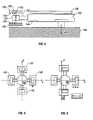
- FIG. 1is a side view of a wafer positioning apparatus according to an embodiment of the invention.
- FIG. 2is a perspective view of the wafer positioning apparatus and the drive and force cancellation motors of the apparatus of FIG. 1.
- FIG. 3is a perspective view of the stage of the wafer positioning apparatus.
- FIG. 4is a cross-sectional side view of part of the stage.
- FIGS. 5 and 6are diagrammatic views of the stage moving in the X-direction.
- FIG. 7is a side view of a portion of the stage and a portion of a drive motor.
- FIG. 8is a view of the bottom surface of the stage.
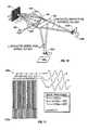
- FIG. 9is a drawing of an interferometric encoder used in connection with the wafer positioning apparatus of FIG. 1.
- FIG. 10is a drawing of portions of the interferometric encoder, showing an optical path signal.
- FIG. 11is a schematic representation of three detector arrays of the interferometric encoder, as well as detector array signals, and an interference pattern associated with the detector arrays.
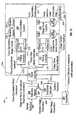
- FIG. 12is a block diagram of a stage control system that can be used to control the stage of the apparatus of FIG. 1.
- FIG. 13is a block diagram of a digital controller of the stage control system of FIG. 12.
- a semiconductor wafer positioning apparatus 100includes a small-motion X-Y stage 102 that can be used to support, for example, a semiconductor wafer 106 .
- Stage 102is capable of moving the wafer 106 over a small field in the X and Y directions.
- the field sizeis 35 ⁇ 35 millimeters square and the precision of the motion is 10 nanometers.
- Stage 102is supported by a platen 104 .
- Air bearings 144 a to 144 doperate between the stage and the platen.
- the stage/platen assemblyis placed on an optical table 124 , which is mounted on vibration isolated legs 122 .
- Two large-motion stages 108 and 110move an equipment box 116 along the X-axis and along the Y-axis, respectively.
- the large motion field sizeis 300 ⁇ 300 millimeters.
- the equipment box 116may contain a microlithography laser 118 , an inspection lens system 120 , or other processing equipment.
- the combination of the stacked stages 102 , 108 , and 110provides de-coupling of the large motion for the heavy load processing equipment 118 , 120 from the high-speed and high-precision small motion for the light stage 102 that supports the wafer.
- Stage 102is movable in the X and Y directions, driven by two pairs of drive motors 112 a, 112 c, and 112 b, 112 d, respectively (FIG. 2).
- the four drive motorslie on the same plane as the stage and are arranged symmetrically around the stage on opposite sides of the stage. They provide drive forces directly to stage 102 without any mechanical contact.
- the motorscan rotate the stage around the Z direction (yaw).
- stage 102has four wings 130 a to 130 d. At the free end of each wing, e.g., 130 a, there are two oppositely magnetized permanent magnets, e.g., 132 a and 134 a.
- the permanent magnetsare placed in a gap 160 formed between two stationary coils 140 and 142 (FIG. 4).
- the stationary coilsare formed on the surfaces of a magnetically permeable material 138 , which acts as a return plate for magnetic flux lines 150 originating from the permanent magnets (FIG. 7).
- the permanent magnetsform the armature of the motor and the stationary coils with the return plate form the stator part of the motor.
- the permanent magnetsmay be Iron Neodymium Boron and the magnetically permeable material may be soft iron.
- the dimensions of the coils of the four motorsare chosen to be wide enough so that any movement in one direction (e.g., X) will maintain the flux lines of the permanent magnets in the other direction (e.g., Y) fully coupled with the coils.
- four drive motorsare used to drive stage 102 .
- three or more than four motorsmay be used (three motors constitute the minimum need to control three degrees of freedom).
- the four-motor configurationcan also utilize the minimum coil size necessary to cover a rectilinear field size. A short coil length results in low power losses.
- the drive coilis split into two coils: top coil 140 and bottom coil 142 .
- the two coils 140 , 142may be connected in series or in parallel, or may be driven independently of each other in order to provide control over the forces generated by the two halves of the drive coil.
- This arrangementcan be used to create small roll (rotation around the X axis) and pitch (rotation around the Y axis) motions in addition to the X, Y and yaw.
- Active control of roll and pitch motionscan be used to compensate for imperfections in manufacturing tolerances that could lead to misalignment of the stage while ensuring that no net moments are applied to the air bearings 144 a - 144 d (FIG.
- Heatis generated at the coils 140 , 142 . Because the coils are bonded to the magnetically permeable material 138 , they can be cooled without disturbing motion of the stage and any precision metrology that may be embedded in the stage.
- the statorsincluding the top and bottom coils 140 , 142 and the magnetically permeable material 138 , are kinematically mounted to the platen.
- This constructionallows the stators to change size due to thermal expansion without stressing the platen, and reduces heat conduction from the stators to the platen, thereby allowing the temperature control of the stators to be simple and inexpensive.
- the platenis kinematically mounted to a sub-frame that is allowed to expand thermally without affecting precision metrology.
- air bearings 144 a to 144 doperate between the bottom surface 170 of stage 102 and the top surface of platen 102 .
- the stiffness of the air bearingsis improved by pre-loading the bearings with a vacuum 146 drawn in the gap 180 between stage 102 and the platen 104 , as shown in FIG. 1. Because the air bearing stiffness is controlled, the small-motion stage is constrained in the Z direction and with respect to rotation around the X-axis (roll) and around the Y-axis (pitch).
- Air bearingsprovide a frictionless support between the stationary platen and the stage that is free of high-spatial frequency kinematic errors.
- a one-time metrology processcan easily map the small amplitude of built-in form errors that do exist in the platen.
- the movable magnet configurationfacilitates a large fluid bearing pre-load by offsetting the magnets in the vertical gap between the drive coils and return flux paths.
- the extra pre-load provided by the magnetscontributes to improved bearing stiffness, which has the benefits of good precision, fast settling time, and small servo-tracking errors.
- the plane of action of the drive motorsis matched to the plane containing the center of gravity of the moving components. Forces that drive the center of gravity of the moving components do not cause undesirable deflections of the fluid bearings.
- the de-coupling between drive forces and fluid bearing deflectionsimproves servo loop stiffness and reduces the time required to achieve high precision following an acceleration.
- the air bearingsare not over-constrained.
- An over-constrained air-bearingis difficult to manufacture due to precise tolerances that must be maintained over relatively large distances. Because the bearings do not require precision tolerances in their manufacture, their cost can be low.
- an interferometric encoderincludes a two-dimensional encoder grid 182 , a sensor head 184 , and a connector 186 connecting the sensor to an interface card 188 , which plugs into a computer (not shown).
- the two-dimensional grid 182has a 10-micrometer scale etched on borosilicate glass. The grid is attached to the movable stage.
- the sensor head 184is attached to the platen and includes, as shown in FIG.
- a laser diode source 192directs a light beam 200 focused through the lenses 194 to the grid 182 .
- the beam 200is diffracted by the grid and interference patterns 202 a and 202 b are formed from the two separate dimensions of the grid.
- Each of the two interference patterns 202 a and 202 bis imaged onto detector arrays 198 a and 198 b.
- the detector arraysgenerate signals that can be processed to make accurate phase measurements.
- the interference patternsmove across the detector arrays, generating, as shown in FIG. 11, signals R, S, and T, which are 120 degrees apart in phase. These signals are electronically processed by a computer to provide accurate measurement of the phase. This technique results in phase resolution of 1 part in 2 14 , which corresponds to a length resolution of 0.3 nm.
- the interferometric encodersmay be manufactured by, for example, Micro E (Massachusetts) or Optra, Inc. (Topsfield, Mass.).
- the encodersare insensitive to environmental disturbances such as change in temperature, humidity, or barometric pressure, thus eliminating any need for controlling the ambient environment of the wafer positioning apparatus and thereby providing low cost.
- the enclosed optical path for the encoders beneath the stageis free of turbulence, thus allowing the positioning electronics to operate at a high bandwidth, which allows higher servo loop stiffness.
- Interferometric encodersare relatively inexpensive, have low weight, and are configured in a moving grid configuration, which keeps the sensor head electronics and associated leads stationary. Because there is no lead flexing with movement of the stage, reliability is high.
- the precision of the encodersis locked into the encoder grid. There may be errors in the grid, but these errors can be measured once and the correction can be-part of the metrology control system.
- a look-up table that is established once when the wafer positioning apparatus is assembledcan easily correct the grid errors.
- Position feedbackmay also be implemented by conventional laser interferometer means.
- a force cancellation systemis provided as an integral component of the wafer positioning apparatus.
- the force cancellation systemincludes four force cancellation motors 114 a to 114 d co-planar with stage 102 and arranged around the stage.
- the cancellation motorsapply cancellation forces to stationary portions of the wafer positioning apparatus, which are directed opposite to the forces generated by the planar motion of the stage.
- Integral force cancellationallows much higher accelerations and less wait time after acceleration intervals and before full system accuracy is achieved.
- the force canceling capabilityalso helps to prevent the stage from shaking any precision components that move with the stage.
- the plane of action of force cancellationis also located in the same plane that will contain the center of gravity of the moving parts of the apparatus (stage 102 combined with any component that the stage is designed to support and move). Because both the drive forces and cancellation forces are on the same plane, no net moments are created out of the plane that may cause deflections in the stage and may result in lower precision. This planar configuration results in high servo loop stiffness, fast settling, and high precision.
- control system 50the main components of control system 50 are the trajectory planner 200 and the digital controller 210 .
- the trajectory planner 200receives a Description of a desired trajectory 202 and produces set points for the stage position servo, and the corresponding force feed-forward commands for both the stage drive motors 230 and the force cancellation motors 240 .
- the trajectory planneris configured to compensate for phase lag between the stage drive feed-forward commands and the force cancellation feed-forward commands.
- the digital controller 210receives the stage position and feed-forward commands 204 for the drive and force cancellation motors from trajectory planner 200 .
- the digital controller 210also receives feedback signals 244 , 234 , and 211 from force cancellation sensors 242 , stage position sensors 232 , and drive motor analog controllers 212 , respectively.
- the digital controllerprocesses the sensor signals 242 , 234 , and 211 to determine the state of the wafer positioning apparatus, compares the state to the desired state, and generates the proper correction signals 213 and 215 , which are applied to analog controllers 212 and 214 .
- the digital controlleralso provides the state information 246 to a parameter estimator 220 .
- Analog controllers 212 and 214control the currents to stage drive motor coils 216 and the force cancellation motor coils 218 , respectively.
- Drive motor analog controller 212provides a drive motor feedback signal 211 to the digital controller.
- Drive motor feedback signal 211is an estimate of the velocity of the stage calculated using a model of the drive motor and measurement of the drive coil voltage and current.
- Analog controllers 212 and 214provide relatively large currents 224 and 222 required to drive the linear drive and force cancellation motors, respectively.
- Each analog controllerhas linear dual output stages.
- the dual output stagescan be connected in parallel to provide double the drive current into a low impedance coil.
- the dual outputscan also be driven in a master/slave configuration in order to drive the top/bottom coils of each stage drive motor.
- the slave outputmay deliver a multiple between 0.95 and 1.05 of the current delivered by the master. This fixed ratio can be adjusted to compensate for manufacturing tolerances in the wafer positioning apparatus and the drive motors and thereby ensure that the net drive force applied by each drive motor is applied at the center of gravity of the moving components.
- the digital controllerreceives stage position feedback 234 from stage drive system 230 through four channels of position sensors 232 (encoders or interferometers). Because the stage has only three degrees of freedom, one channel of feedback is redundant. This redundancy is exploited in the digital controller to derive a best-fit estimate of stage position and also to provide an estimate of the quality of the sensor signals. The quality of the sensor signals is simply the residual between the best-fit estimate of stage position and the four measurements from which the fit was estimated. The digital controller software monitors the quality measurement and will execute shutdown procedures if the quality exceeds preset limits.
- Vibration sensors 242are included on the wafer positioning apparatus to monitor the force cancellation performance.
- a calibration system 260monitors the force cancellation performance during the manufacture of the wafer positioning apparatus and adjusts the feed-forward gains 208 (static parameters).
- a parameter estimator 220is also provided in the controlling software.
- the parameter estimator 220looks at the desired trajectory and the actual state variables of the stage drive system and force cancellation system and derives an improved estimate 206 of the parameters to be used by the trajectory planner 200 .
- the goal of the parameter estimatoris to drive the dynamic error of the stage to be near zero at all times. For this condition to occur, the trajectory planner 200 must provide force commands that correspond nearly perfectly to the desired position trajectory. Nearly perfect correspondence requires excellent knowledge of amplifier gains, stage mass, motor location relative to the stage, and similar parameters. Errors in the model of the wafer positioning apparatus may lead to tracking errors when the stage executes a motion profile.
- the stagewill execute a trajectory with less settling time.
- the limits on tracking errorscan be set ever tighter in the digital controller as the model is improved. Very tight tolerances on tracking errors allow the digital controller to detect errors, collisions, or other unanticipated events faster, which ensures good safety of the system.
- the calibration system 260measures and corrects geometric errors in stage position sensors 232 and establishes baseline parameter values that will be subsequently improved by the parameter estimator.
- the calibration system 260can also be used to make off-line calibration. For off-line calibration the calibration system 260 may use additional sensors and software.
- the trajectory planner 200is designed to perform specific tasks. For the task of re-positioning a semiconductor element for the purpose of memory repair, for example, the trajectory is specified as a sequence of segments.
- the segmentsinclude a Position/Velocity/Time segment, and a Cruise-velocity/Distance segment.
- the Position/Velocity/Time segmentspecifies initial and final position and velocities and the time allotted to perform the movement.
- the trajectory plannerdetermines the position and corresponding force profiles necessary to satisfy the end-point conditions.
- the path taken along the movementis not constrained.
- a special condition of zero timeindicates that the trajectory planner should use the minimum time necessary for the movement subject to actuator or other limitations.
- the Cruise-velocity/Distance segmentis used to perform most processing operations. Only the length of this segment is specified. The velocity for the segment is specified by the endpoint of the preceding segment. The Cruise-velocity/Distance segment cannot be the first segment in a trajectory. Processing commands may be linked to the Cruise-velocity/Distance segment type.
- the trajectory planner 200expands a trajectory specified as an ordered list of trajectory segments into a list of trajectory points that will be issued at a pre-determined update rate to the digital controller.
- the trajectory planneroperates in near real-time at a slight preview interval to the actual motion.
- a trajectory buffer 300(FIG. 13) exists between the trajectory planner, the digital controller and the parameter estimator.
- the trajectory buffer 300allows the rate of execution of the trajectory planner to be de-coupled from the digital controller rate.
- the trajectory plannermust run sufficiently often to ensure that the trajectory buffer is never empty. There is a very slight delay at the start of a motion sequence that allows the trajectory planner to get far enough ahead of the digital controller that the buffer will not be empty. After the initial start-up delay (a few milliseconds), the time required to perform a motion is completely dependent upon the physical limitations of the hardware. There are no further software induced delays in the system.
- the trajectory planneruses closed-form motion profiles in order to construct the trajectory segments.
- a linearly varying cycloidal acceleration profileis used for small motion in order to implement a Position/Velocity/Time segment type:
- Ais Acceleration profile (or equivalently, force profile)
- k o and k lare profile constants that are used to match trajectory endpoints
- Tis segment duration (time)
- tis time (independent variable)
- This profileis a smoothly changing force profile over the course of the segment and has sufficient flexibility to meet the end-point constraints of the trajectory segment. Because the profile is smooth, the feed-forward force signals that correspond to the profile are smooth too. This result is beneficial because the feed-forward force signals are applied directly to the amplifiers and motors without additional filtering. Because the feed-forward force signals are applied in an open-loop configuration, the dynamics of the wafer positioning apparatus do not influence the applied force signals, thereby providing dramatically simple system dynamics.
- the key elements of the digital controller 210are a trajectory buffer 300 , a command buffer interface 302 , a monitor buffer interface 304 , a feedback transform 306 , an error detection block 308 , a control law 310 , an output transform 314 , and a motor state feedback block 312 .
- the trajectory plannerpasses trajectory commands to the digital controller via trajectory buffer 300 . Also, the digital recorder passes back data to parameter estimator 220 via trajectory buffer 300 .
- This arrangementis implemented using a block of shared memory that can be accessed by both the low level processor (digital controller) as well as the higher level processor (trajectory planner and parameter estimator).
- the command buffer interface 302extracts force feed-forward and position set-point commands from trajectory buffer 300 and uses them in each update of the digital controller.
- Monitor buffer 304enters state information to parameter estimator 220 by inserting the measured data into trajectory buffer 300 .
- stage sensor interface 316Four channels of stage position are measured through stage sensor interface 316 .
- the four sensor readingsare converted into a best fit estimate of the three degrees of freedom stage position (X, Y, yaw) by feedback transform 306 .
- the quality of the sensorsis also computed and monitored, along with additional measurements from the amplifier, by error detection block 308 .
- Error detection block 308initiates shutdown procedures whenever a failure is detected based on out-of-limits measurements. Shutdown may be initiated for poor sensor quality (e.g., excessive residuals in the feedback transform), if the position error exceeds a preset limit, if the estimated stage velocity exceeds a preset limit, and if the motor temperature or current exceeds a preset limit.
- Control law 310receives as input a three-degree-of-freedom position error signal and additional state information from the motors and produces three force commands that are designed to drive the tracking error to zero.
- the three forces resulting from control law 310are transformed by output transform 314 into a minimum power vector that is applied in the moving magnet coordinate system by the four stage drive motors.
- the error forcesare summed, in the moving magnet coordinate system, with the feed-forward force commands coming directly from the trajectory buffer.
- the resulting vector sum of forcesis sent to the four analog controllers.
- Stage motor state feedback block 312monitors feedback from the analog controller. Monitored variables include motor current, armature velocity, and stator temperature.
- stage control systemprovides highly predictable response of the stage to force commands.
- the high degree of predictabilityallows the estimation of feed-forward forces to be made with great accuracy.
- the actual force required to drive the stagemay be slightly different from the predicted force profile. However, because of the high servo loop gains (which are also possible due to the simplicity of the wafer positioning apparatus and the absence of low frequency vibration modes), any errors in the predicted forces can be corrected with minimal tracking error.
- the required-force profilemay be predicted with better than 99 percent accuracy directly from the feed-forward path. Tracking error multiplied by the servo loop gain will generate the residual force required to drive the stage along a prescribed trajectory.
- Another advantage of the control architectureis the partitioning of the computation load amongst multiple processors, such as the trajectory planner and the digital controller.
- the digital controlleris optimized to provide low-latency (measured in microseconds) computation in a highly deterministic faction in order to satisfy closed loop stability criteria.
- the trajectory planneroperates with low deterministic behavior (latency measured in tens to hundreds of milliseconds). While a single processor with a suitable operating system could perform both functions, the partition facilities using multiple processors with a shared memory interface between them. This partition allows a dedicated digital signal processor to be used for the digital controller and a host with near real-time performance (such as UNIX or Windows NT) to implement the trajectory planer.
Landscapes
- Engineering & Computer Science (AREA)
- Physics & Mathematics (AREA)
- Power Engineering (AREA)
- Chemical & Material Sciences (AREA)
- Combustion & Propulsion (AREA)
- Electromagnetism (AREA)
- Condensed Matter Physics & Semiconductors (AREA)
- General Physics & Mathematics (AREA)
- Manufacturing & Machinery (AREA)
- Computer Hardware Design (AREA)
- Microelectronics & Electronic Packaging (AREA)
- Exposure And Positioning Against Photoresist Photosensitive Materials (AREA)
- Exposure Of Semiconductors, Excluding Electron Or Ion Beam Exposure (AREA)
- Container, Conveyance, Adherence, Positioning, Of Wafer (AREA)
- Control Of Position Or Direction (AREA)
- Details Of Measuring And Other Instruments (AREA)
- Length Measuring Devices By Optical Means (AREA)
- Length Measuring Devices With Unspecified Measuring Means (AREA)
- Optical Radar Systems And Details Thereof (AREA)
- Control Of Motors That Do Not Use Commutators (AREA)
- Machine Tool Units (AREA)
- Linear Motors (AREA)
- Vehicle Body Suspensions (AREA)
- Automatic Control Of Machine Tools (AREA)
Abstract
Description
- This invention relates to high-speed precision positioning apparatuses useful for processing of devices such as semiconducting wafers, for micro-scale experimentation, or for high resolution electron microscopy of biological or other samples.[0001]
- Semiconductor processing equipment often requires high-precision positioning of a silicon wafer. Large-size wafers with very small features often require high-precision positioning combined with a large range motion of the wafer stage that supports the wafer.[0002]
- In addition to high precision and a large range motion, high-speed scanning is useful for achieving high manufacturing throughput.[0003]
- A typical example of semiconductor processing equipment is a laser used in microlithography. Certain traditional systems for semiconductor laser processing include a translation stage that can support the wafer and move it under a fixed laser beam. The wafer-supporting translation stage may move along the X or Y directions, for example.[0004]
- In certain processing equipment a linear motor and a bearing system are used to move the wafer-supporting stage along a rail in the X-direction. To move the wafer-supporting stage in the Y-direction an intermediate rail is used that carries the rail and the wafer-supporting stage in the Y-direction while allowing the wafer-supporting stage to slide along the rail in the X-direction.[0005]
- In addition to drive motors, various moving parts, bearings, and wafer, the wafer-supporting stage may carry a position detector. The position detector may be a laser-distance interferometer that is usually heavy, and requires environmental shielding of the optical path and slow motion in order to achieve high accuracy readings.[0006]
- Hollis, U.S. Pat. No. 5,153,494, describes an apparatus capable of moving light loads in X, Y, and yaw (rotation around the Z axis) in limited range and with high speed. Vibrations of the stationary portions of the apparatus are reduced by a momentum-canceling design. The momentum canceling design includes, in addition to the movable wafer-supporting stage, a non-coplanar moving element that moves in a momentum canceling manner with respect to the movable wafer-supporting stage. The motors include fixed permanent magnets and coils that are attached to the wafer-supporting stage and move along with the wafer-supporting stage.[0007]
- Trumper, U.S. Pat. No. 5,196,745, describes an apparatus capable of providing movement in the 200 to 300 mm range in one or two degrees of freedom and having precision control in the 10 nm range in the remaining degrees of freedom. Linear motion of the wafer-supporting stage is provided by a motor having an array of permanent magnets attached to the movable wafer-supporting stage and a fixed array of commutating coils attached to the stator. The commutating coils have coupled magnetic flux lines. Current is allowed to flow only in those sections of the array where the motion takes place, in order to reduce energy losses in the coils. The motion is facilitated by magnetic bearings.[0008]
- In one aspect, the invention features a device positioning apparatus having a stage configured to support the device, a platen supporting the stage, and a plurality of drive motors, co-planar with the stage and arranged around the stage, that apply drive forces directly to the stage without any mechanical contact to the stage. The drive forces impart planar motion to the stage in at least three degrees of freedom of motion. A plurality of fluid bearings operate between the stage and the platen and constrain the planar motion of the stage in all remaining degrees of freedom. A controller connected to the drive motors controls operation of the drive motors. Each drive motor has a top stationary coil, a bottom stationary coil, and a movable magnet adapted to move in a gap of predetermined length formed in-between the top and bottom stationary coils.[0009]
- The arrangement according to the invention makes it possible, in certain embodiments, for there to be only one monolithic movable part. This arrangement allows the stage to be made very stiff, which in turn promotes use of very high servo gains in the controller. Benefits of this arrangement can include good precision, fast settling time, and small servo-tracking error.[0010]
- Because the motors are provided in a movable magnet configuration, the drive coils can remain stationary, thus eliminating any need to attach leads to the movable stage. This arrangement improves the reliability of the coils, because their leads are not flexed.[0011]
- In some embodiments the stage may be a small-motion stage, and the apparatus may include a large-motion stage that moves on a plane parallel to a plane of motion of the small-motion stage. This arrangement allows a heavy load processing equipment, e.g., laser, to be carried by a low performance large-motion element that can scan the full range of the wafer. The light load wafer can be supported by a high-precision, high-speed, small-motion stage that scans the small range of the individual devices on the wafer.[0012]
- In another aspect, the invention includes a force cancellation system that applies cancellation forces to the device positioning apparatus. The cancellation forces are co-planar with the center of gravity of the stage and any components that move with the stage and cancel forces generated by the planar motion of the stage. Because both the drive forces and cancellation forces are on the same plane, no net moments are created out of the plane that may cause deflections in the stage and may result in lower precision. This planar configuration results in high servo loop stiffness, a fast settling time, and high precision.[0013]
- In another aspect, the invention features a position detector that includes at least one interferometric encoder. The encoders are insensitive to environmental disturbances such as change in temperature, humidity, or barometric pressure, thus reducing the need for controlling the ambient environment of the positioning apparatus and thereby reducing cost. Interferometric encoders can be relatively inexpensive, have low weight, and can be configured in a moving grid configuration, which keeps the read head electronics and associated leads stationary. Reliability can be improved by eliminating lead flexing with movement of the stage.[0014]
- In another aspect, the invention features a controller that controls the operation of the drive motor and includes a trajectory planner that receives a description of a desired trajectory, produces stage drive commands and force cancellation commands for the drive motors and the force cancellation system, respectively, and compensates for phase lag between the stage drive commands and the force cancellation commands. The controller also includes a digital controller that receives commands from the trajectory planner and feedback signals, and compares the feedback signals to the commands and generates correction signals for the drive motors.[0015]
- Other features and advantages of the invention will be apparent from the following detailed description, the drawings, and the claims.[0016]
- FIG. 1 is a side view of a wafer positioning apparatus according to an embodiment of the invention.[0017]
- FIG. 2 is a perspective view of the wafer positioning apparatus and the drive and force cancellation motors of the apparatus of FIG. 1.[0018]
- FIG. 3 is a perspective view of the stage of the wafer positioning apparatus.[0019]
- FIG. 4 is a cross-sectional side view of part of the stage.[0020]
- FIGS. 5 and 6 are diagrammatic views of the stage moving in the X-direction.[0021]
- FIG. 7 is a side view of a portion of the stage and a portion of a drive motor.[0022]
- FIG. 8 is a view of the bottom surface of the stage.[0023]
- FIG. 9 is a drawing of an interferometric encoder used in connection with the wafer positioning apparatus of FIG. 1.[0024]
- FIG. 10 is a drawing of portions of the interferometric encoder, showing an optical path signal.[0025]
- FIG. 11 is a schematic representation of three detector arrays of the interferometric encoder, as well as detector array signals, and an interference pattern associated with the detector arrays.[0026]
- FIG. 12 is a block diagram of a stage control system that can be used to control the stage of the apparatus of FIG. 1.[0027]
- FIG. 13 is a block diagram of a digital controller of the stage control system of FIG. 12.[0028]
- Referring to FIG. 1, a semiconductor[0029]
wafer positioning apparatus 100 according to the invention includes a small-motion X-Y stage 102 that can be used to support, for example, asemiconductor wafer 106.Stage 102 is capable of moving thewafer 106 over a small field in the X and Y directions. In one example the field size is 35×35 millimeters square and the precision of the motion is 10 nanometers. - [0030]
Stage 102 is supported by aplaten 104.Air bearings 144ato144doperate between the stage and the platen. The stage/platen assembly is placed on an optical table124, which is mounted on vibrationisolated legs 122. - Two large-[0031]
motion stages equipment box 116 along the X-axis and along the Y-axis, respectively. In one example, the large motion field size is 300×300 millimeters. - The[0032]
equipment box 116 may contain a microlithography laser118, aninspection lens system 120, or other processing equipment. The combination of the stackedstages load processing equipment 118,120 from the high-speed and high-precision small motion for thelight stage 102 that supports the wafer. - [0033]
Stage 102 is movable in the X and Y directions, driven by two pairs ofdrive motors - Referring to FIG. 3,[0034]
stage 102 has fourwings 130ato130d.At the free end of each wing, e.g.,130a,there are two oppositely magnetized permanent magnets, e.g.,132aand134a.The permanent magnets are placed in a gap160 formed between twostationary coils 140 and142 (FIG. 4). The stationary coils are formed on the surfaces of a magneticallypermeable material 138, which acts as a return plate formagnetic flux lines 150 originating from the permanent magnets (FIG. 7). The permanent magnets form the armature of the motor and the stationary coils with the return plate form the stator part of the motor. Because a current is applied to the stationary coils, a force is induced that acts on the permanent magnets, causing them to move together with the stage. In one example, the permanent magnets may be Iron Neodymium Boron and the magnetically permeable material may be soft iron. - Referring to FIGS. 5 and 6, the dimensions of the coils of the four motors are chosen to be wide enough so that any movement in one direction (e.g., X) will maintain the flux lines of the permanent magnets in the other direction (e.g., Y) fully coupled with the coils.[0035]
- In the moving magnet configuration, the point at which the drive force is applied to each wing of the stage remains stationary relative to the center of the movable stage. This arrangement results in a simple servo controller.[0036]
- With reference to FIG. 2, four drive motors are used to drive[0037]
stage 102. In other embodiments three or more than four motors may be used (three motors constitute the minimum need to control three degrees of freedom). The four-motor configuration can also utilize the minimum coil size necessary to cover a rectilinear field size. A short coil length results in low power losses. - With reference to FIGS. 4 and 7, the drive coil is split into two coils:[0038]
top coil 140 andbottom coil 142. The twocoils air bearings 144a-144d(FIG. 8) as a result of motor forces. Ifcoils top coil 140 relative to the current inbottom coil 142 can be controlled so as to ensure that the resultant net force is applied in the plane of the center of gravity of the moving components. - Heat is generated at the[0039]
coils permeable material 138, they can be cooled without disturbing motion of the stage and any precision metrology that may be embedded in the stage. - The stators, including the top and[0040]
bottom coils permeable material 138, are kinematically mounted to the platen. This construction allows the stators to change size due to thermal expansion without stressing the platen, and reduces heat conduction from the stators to the platen, thereby allowing the temperature control of the stators to be simple and inexpensive. In an alternative construction, the platen is kinematically mounted to a sub-frame that is allowed to expand thermally without affecting precision metrology. - Referring to FIG. 8,[0041]
air bearings 144ato144doperate between thebottom surface 170 ofstage 102 and the top surface ofplaten 102. The stiffness of the air bearings is improved by pre-loading the bearings with avacuum 146 drawn in thegap 180 betweenstage 102 and theplaten 104, as shown in FIG. 1. Because the air bearing stiffness is controlled, the small-motion stage is constrained in the Z direction and with respect to rotation around the X-axis (roll) and around the Y-axis (pitch). - Air bearings provide a frictionless support between the stationary platen and the stage that is free of high-spatial frequency kinematic errors. A one-time metrology process can easily map the small amplitude of built-in form errors that do exist in the platen.[0042]
- The movable magnet configuration facilitates a large fluid bearing pre-load by offsetting the magnets in the vertical gap between the drive coils and return flux paths. The extra pre-load provided by the magnets contributes to improved bearing stiffness, which has the benefits of good precision, fast settling time, and small servo-tracking errors.[0043]
- The plane of action of the drive motors is matched to the plane containing the center of gravity of the moving components. Forces that drive the center of gravity of the moving components do not cause undesirable deflections of the fluid bearings. The de-coupling between drive forces and fluid bearing deflections improves servo loop stiffness and reduces the time required to achieve high precision following an acceleration.[0044]
- The air bearings are not over-constrained. An over-constrained air-bearing is difficult to manufacture due to precise tolerances that must be maintained over relatively large distances. Because the bearings do not require precision tolerances in their manufacture, their cost can be low.[0045]
- One method of position feedback is based on the use of[0046]
interferometric encoders 136ato136dplaced at thebottom surface 170 of the stage, as shown in FIG. 8. Referring to FIG. 9, an interferometric encoder includes a two-dimensional encoder grid 182, asensor head 184, and aconnector 186 connecting the sensor to aninterface card 188, which plugs into a computer (not shown). The two-dimensional grid 182 has a 10-micrometer scale etched on borosilicate glass. The grid is attached to the movable stage. Thesensor head 184 is attached to the platen and includes, as shown in FIG. 10, alaser diode source 192,lenses 194, prism-mirrors 196, anddetectors laser 192 directs alight beam 200 focused through thelenses 194 to thegrid 182. Thebeam 200 is diffracted by the grid andinterference patterns 202aand202bare formed from the two separate dimensions of the grid. Each of the twointerference patterns 202aand202bis imaged ontodetector arrays - The interferometric encoders may be manufactured by, for example, Micro E (Massachusetts) or Optra, Inc. (Topsfield, Mass.).[0047]
- The encoders are insensitive to environmental disturbances such as change in temperature, humidity, or barometric pressure, thus eliminating any need for controlling the ambient environment of the wafer positioning apparatus and thereby providing low cost. The enclosed optical path for the encoders beneath the stage is free of turbulence, thus allowing the positioning electronics to operate at a high bandwidth, which allows higher servo loop stiffness.[0048]
- Interferometric encoders are relatively inexpensive, have low weight, and are configured in a moving grid configuration, which keeps the sensor head electronics and associated leads stationary. Because there is no lead flexing with movement of the stage, reliability is high.[0049]
- The precision of the encoders is locked into the encoder grid. There may be errors in the grid, but these errors can be measured once and the correction can be-part of the metrology control system. A look-up table that is established once when the wafer positioning apparatus is assembled can easily correct the grid errors.[0050]
- Position feedback may also be implemented by conventional laser interferometer means.[0051]
- In order to cancel forces caused by the movements of the stage, a force cancellation system is provided as an integral component of the wafer positioning apparatus. Referring again to FIG. 2, the force cancellation system includes four[0052]
force cancellation motors 114ato114dco-planar withstage 102 and arranged around the stage. The cancellation motors apply cancellation forces to stationary portions of the wafer positioning apparatus, which are directed opposite to the forces generated by the planar motion of the stage. - Integral force cancellation allows much higher accelerations and less wait time after acceleration intervals and before full system accuracy is achieved. The force canceling capability also helps to prevent the stage from shaking any precision components that move with the stage.[0053]
- The plane of action of force cancellation is also located in the same plane that will contain the center of gravity of the moving parts of the apparatus ([0054]
stage 102 combined with any component that the stage is designed to support and move). Because both the drive forces and cancellation forces are on the same plane, no net moments are created out of the plane that may cause deflections in the stage and may result in lower precision. This planar configuration results in high servo loop stiffness, fast settling, and high precision. - Referring to FIG. 12 the main components of[0055]
control system 50 are thetrajectory planner 200 and thedigital controller 210. - The[0056]
trajectory planner 200 receives a Description of a desiredtrajectory 202 and produces set points for the stage position servo, and the corresponding force feed-forward commands for both thestage drive motors 230 and theforce cancellation motors 240. The trajectory planner is configured to compensate for phase lag between the stage drive feed-forward commands and the force cancellation feed-forward commands. - The[0057]
digital controller 210 receives the stage position and feed-forward commands204 for the drive and force cancellation motors fromtrajectory planner 200. Thedigital controller 210 also receives feedback signals244,234, and211 fromforce cancellation sensors 242,stage position sensors 232, and drivemotor analog controllers 212, respectively. The digital controller processes the sensor signals242,234, and211 to determine the state of the wafer positioning apparatus, compares the state to the desired state, and generates the proper correction signals213 and215, which are applied toanalog controllers state information 246 to aparameter estimator 220. - [0058]
Analog controllers motor analog controller 212 provides a drivemotor feedback signal 211 to the digital controller. Drivemotor feedback signal 211 is an estimate of the velocity of the stage calculated using a model of the drive motor and measurement of the drive coil voltage and current. - [0059]
Analog controllers large currents - The digital controller receives[0060]
stage position feedback 234 fromstage drive system 230 through four channels of position sensors232 (encoders or interferometers). Because the stage has only three degrees of freedom, one channel of feedback is redundant. This redundancy is exploited in the digital controller to derive a best-fit estimate of stage position and also to provide an estimate of the quality of the sensor signals. The quality of the sensor signals is simply the residual between the best-fit estimate of stage position and the four measurements from which the fit was estimated. The digital controller software monitors the quality measurement and will execute shutdown procedures if the quality exceeds preset limits. - Vibration sensors[0061]242 (either geophones or accelerometers) are included on the wafer positioning apparatus to monitor the force cancellation performance. A
calibration system 260 monitors the force cancellation performance during the manufacture of the wafer positioning apparatus and adjusts the feed-forward gains208 (static parameters). - A[0062]
parameter estimator 220 is also provided in the controlling software. Theparameter estimator 220 looks at the desired trajectory and the actual state variables of the stage drive system and force cancellation system and derives animproved estimate 206 of the parameters to be used by thetrajectory planner 200. The goal of the parameter estimator is to drive the dynamic error of the stage to be near zero at all times. For this condition to occur, thetrajectory planner 200 must provide force commands that correspond nearly perfectly to the desired position trajectory. Nearly perfect correspondence requires excellent knowledge of amplifier gains, stage mass, motor location relative to the stage, and similar parameters. Errors in the model of the wafer positioning apparatus may lead to tracking errors when the stage executes a motion profile. As the system model gets better, due to operation of theparameter estimator 220 leading to continuous improvement in accuracy of the model, the stage will execute a trajectory with less settling time. In addition to improved performance, the limits on tracking errors can be set ever tighter in the digital controller as the model is improved. Very tight tolerances on tracking errors allow the digital controller to detect errors, collisions, or other unanticipated events faster, which ensures good safety of the system. - The[0063]
calibration system 260 measures and corrects geometric errors instage position sensors 232 and establishes baseline parameter values that will be subsequently improved by the parameter estimator. Thecalibration system 260 can also be used to make off-line calibration. For off-line calibration thecalibration system 260 may use additional sensors and software. - The[0064]
trajectory planner 200 is designed to perform specific tasks. For the task of re-positioning a semiconductor element for the purpose of memory repair, for example, the trajectory is specified as a sequence of segments. The segments include a Position/Velocity/Time segment, and a Cruise-velocity/Distance segment. - The Position/Velocity/Time segment specifies initial and final position and velocities and the time allotted to perform the movement. The trajectory planner determines the position and corresponding force profiles necessary to satisfy the end-point conditions. The path taken along the movement is not constrained. A special condition of zero time indicates that the trajectory planner should use the minimum time necessary for the movement subject to actuator or other limitations.[0065]
- The Cruise-velocity/Distance segment is used to perform most processing operations. Only the length of this segment is specified. The velocity for the segment is specified by the endpoint of the preceding segment. The Cruise-velocity/Distance segment cannot be the first segment in a trajectory. Processing commands may be linked to the Cruise-velocity/Distance segment type.[0066]
- Other types of segments may be used in other applications.[0067]
- The[0068]
trajectory planner 200 expands a trajectory specified as an ordered list of trajectory segments into a list of trajectory points that will be issued at a pre-determined update rate to the digital controller. The trajectory planner operates in near real-time at a slight preview interval to the actual motion. A trajectory buffer300 (FIG. 13) exists between the trajectory planner, the digital controller and the parameter estimator. Thetrajectory buffer 300 allows the rate of execution of the trajectory planner to be de-coupled from the digital controller rate. The trajectory planner must run sufficiently often to ensure that the trajectory buffer is never empty. There is a very slight delay at the start of a motion sequence that allows the trajectory planner to get far enough ahead of the digital controller that the buffer will not be empty. After the initial start-up delay (a few milliseconds), the time required to perform a motion is completely dependent upon the physical limitations of the hardware. There are no further software induced delays in the system. - The trajectory planner uses closed-form motion profiles in order to construct the trajectory segments. In one example, a linearly varying cycloidal acceleration profile is used for small motion in order to implement a Position/Velocity/Time segment type:[0069]
- A(t)=(sin(π*t/T)*(ko+kl*t)
- Where:[0070]
- A is Acceleration profile (or equivalently, force profile)[0071]
- k[0072]oand klare profile constants that are used to match trajectory endpoints
- T is segment duration (time)[0073]
- t is time (independent variable)[0074]
- This profile is a smoothly changing force profile over the course of the segment and has sufficient flexibility to meet the end-point constraints of the trajectory segment. Because the profile is smooth, the feed-forward force signals that correspond to the profile are smooth too. This result is beneficial because the feed-forward force signals are applied directly to the amplifiers and motors without additional filtering. Because the feed-forward force signals are applied in an open-loop configuration, the dynamics of the wafer positioning apparatus do not influence the applied force signals, thereby providing dramatically simple system dynamics.[0075]
- Referring to FIG. 13 the key elements of the[0076]
digital controller 210 are atrajectory buffer 300, acommand buffer interface 302, amonitor buffer interface 304, afeedback transform 306, anerror detection block 308, acontrol law 310, anoutput transform 314, and a motorstate feedback block 312. - The trajectory planner passes trajectory commands to the digital controller via[0077]
trajectory buffer 300. Also, the digital recorder passes back data toparameter estimator 220 viatrajectory buffer 300. This arrangement is implemented using a block of shared memory that can be accessed by both the low level processor (digital controller) as well as the higher level processor (trajectory planner and parameter estimator). - The[0078]
command buffer interface 302 extracts force feed-forward and position set-point commands fromtrajectory buffer 300 and uses them in each update of the digital controller. - [0079]
Monitor buffer 304 enters state information toparameter estimator 220 by inserting the measured data intotrajectory buffer 300. - Four channels of stage position are measured through[0080]
stage sensor interface 316. The four sensor readings are converted into a best fit estimate of the three degrees of freedom stage position (X, Y, yaw) byfeedback transform 306. The quality of the sensors is also computed and monitored, along with additional measurements from the amplifier, byerror detection block 308.Error detection block 308 initiates shutdown procedures whenever a failure is detected based on out-of-limits measurements. Shutdown may be initiated for poor sensor quality (e.g., excessive residuals in the feedback transform), if the position error exceeds a preset limit, if the estimated stage velocity exceeds a preset limit, and if the motor temperature or current exceeds a preset limit. - [0081]
Control law 310 receives as input a three-degree-of-freedom position error signal and additional state information from the motors and produces three force commands that are designed to drive the tracking error to zero. The three forces resulting fromcontrol law 310 are transformed byoutput transform 314 into a minimum power vector that is applied in the moving magnet coordinate system by the four stage drive motors. The error forces are summed, in the moving magnet coordinate system, with the feed-forward force commands coming directly from the trajectory buffer. The resulting vector sum of forces is sent to the four analog controllers. - Stage motor state feedback block[0082]312 monitors feedback from the analog controller. Monitored variables include motor current, armature velocity, and stator temperature.
- The stage control system provides highly predictable response of the stage to force commands. The high degree of predictability allows the estimation of feed-forward forces to be made with great accuracy.[0083]
- The actual force required to drive the stage may be slightly different from the predicted force profile. However, because of the high servo loop gains (which are also possible due to the simplicity of the wafer positioning apparatus and the absence of low frequency vibration modes), any errors in the predicted forces can be corrected with minimal tracking error. In one example, the required-force profile may be predicted with better than 99 percent accuracy directly from the feed-forward path. Tracking error multiplied by the servo loop gain will generate the residual force required to drive the stage along a prescribed trajectory.[0084]
- Because the vast majority of the forces (both drive and force cancellation) are predetermined, very effective force canceling is possible. This high degree of cancellation is possible without interaction or coupling of the system dynamics.[0085]
- The use of the feed-forward model to generate the majority of the drive signal provides good safety. Because the closed loop servo controller supplies very little force, it is possible to set a very tight tolerance on position error. The tight tolerance on servo error allows faults to be detected and shutdown procedures to commence before substantial damage can be done to the system or any personnel. It is easy to detect when a maintenance person, for instance, applies an external disturbance to the wafer positioning apparatus such as via unanticipated touching.[0086]
- Another advantage of the control architecture is the partitioning of the computation load amongst multiple processors, such as the trajectory planner and the digital controller. The digital controller is optimized to provide low-latency (measured in microseconds) computation in a highly deterministic faction in order to satisfy closed loop stability criteria. The trajectory planner operates with low deterministic behavior (latency measured in tens to hundreds of milliseconds). While a single processor with a suitable operating system could perform both functions, the partition facilities using multiple processors with a shared memory interface between them. This partition allows a dedicated digital signal processor to be used for the digital controller and a host with near real-time performance (such as UNIX or Windows NT) to implement the trajectory planer.[0087]
- There has been described novel and improved apparatus and techniques for high-speed precision positioning. The invention is to be construed as embracing each and every novel feature and novel combination of features present in or possessed by the apparatus and technique herein disclosed. It is also evident that those skilled in the art may now make numerous uses and modifications of and departures from the specific embodiments described herein without departing from the inventive concept.[0088]
Claims (55)
Priority Applications (1)
| Application Number | Priority Date | Filing Date | Title |
|---|---|---|---|
| US10/747,552US6949844B2 (en) | 1998-09-18 | 2003-12-29 | High-speed precision positioning apparatus |
Applications Claiming Priority (3)
| Application Number | Priority Date | Filing Date | Title |
|---|---|---|---|
| US09/156,895US6144118A (en) | 1998-09-18 | 1998-09-18 | High-speed precision positioning apparatus |
| US09/613,833US6744228B1 (en) | 1998-09-18 | 2000-07-11 | High-speed precision positioning apparatus |
| US10/747,552US6949844B2 (en) | 1998-09-18 | 2003-12-29 | High-speed precision positioning apparatus |
Related Parent Applications (1)
| Application Number | Title | Priority Date | Filing Date |
|---|---|---|---|
| US09/613,833ContinuationUS6744228B1 (en) | 1998-09-18 | 2000-07-11 | High-speed precision positioning apparatus |
Publications (2)
| Publication Number | Publication Date |
|---|---|
| US20040140780A1true US20040140780A1 (en) | 2004-07-22 |
| US6949844B2 US6949844B2 (en) | 2005-09-27 |
Family
ID=22561554
Family Applications (3)
| Application Number | Title | Priority Date | Filing Date |
|---|---|---|---|
| US09/156,895Expired - LifetimeUS6144118A (en) | 1998-09-18 | 1998-09-18 | High-speed precision positioning apparatus |
| US09/613,833Expired - LifetimeUS6744228B1 (en) | 1998-09-18 | 2000-07-11 | High-speed precision positioning apparatus |
| US10/747,552Expired - Fee RelatedUS6949844B2 (en) | 1998-09-18 | 2003-12-29 | High-speed precision positioning apparatus |
Family Applications Before (2)
| Application Number | Title | Priority Date | Filing Date |
|---|---|---|---|
| US09/156,895Expired - LifetimeUS6144118A (en) | 1998-09-18 | 1998-09-18 | High-speed precision positioning apparatus |
| US09/613,833Expired - LifetimeUS6744228B1 (en) | 1998-09-18 | 2000-07-11 | High-speed precision positioning apparatus |
Country Status (8)
| Country | Link |
|---|---|
| US (3) | US6144118A (en) |
| EP (1) | EP1055163B1 (en) |
| JP (3) | JP4970651B2 (en) |
| KR (1) | KR100583040B1 (en) |
| AT (1) | ATE378625T1 (en) |
| DE (2) | DE19982072T1 (en) |
| TW (1) | TW449680B (en) |
| WO (1) | WO2000017724A1 (en) |
Cited By (17)
| Publication number | Priority date | Publication date | Assignee | Title |
|---|---|---|---|---|
| WO2007133011A1 (en)* | 2006-05-12 | 2007-11-22 | Chungju National University Industry-Academic Cooperation Foundation | Method and apparatus for detecting in-plane position in a planar stage by measuring air gap displacement |
| US20100194328A1 (en)* | 2009-02-05 | 2010-08-05 | Gary Peter Widdowson | System for maintaining thermal stability of a motion stage |
| US20100301028A1 (en)* | 2009-05-29 | 2010-12-02 | Electro Scientific Industries, Inc. | Method and apparatus for hybrid resolution feedback of a motion stage |
| CN102592684A (en)* | 2011-12-12 | 2012-07-18 | 江西理工大学 | Spatial three-dimensionally translatory and two-dimensionally rotary full-compliant parallel mechanism |
| US9202719B2 (en) | 2011-10-27 | 2015-12-01 | The University Of British Columbia | Displacement devices and methods for fabrication, use and control of same |
| WO2016003472A1 (en)* | 2014-07-03 | 2016-01-07 | Newport Corporation | Multi-axis positioning device |
| EP2993688A3 (en)* | 2006-08-31 | 2016-04-20 | Nikon Corporation | Movable body drive method and movable body drive system, pattern formation method and apparatus, exposure method and apparatus, and device manufacturing method |
| US10056816B2 (en) | 2014-06-07 | 2018-08-21 | The University Of British Columbia | Methods and systems for controllably moving multiple moveable stages in a displacement device |
| US10116195B2 (en) | 2014-05-30 | 2018-10-30 | The University Of British Columbia | Displacement devices and methods for fabrication, use and control of same |
| US10222237B2 (en) | 2013-08-06 | 2019-03-05 | The University Of British Columbia | Displacement devices and methods and apparatus for detecting and estimating motion associated with same |
| US10348177B2 (en) | 2014-06-14 | 2019-07-09 | The University Of British Columbia | Displacement devices, moveable stages for displacement devices and methods for fabrication, use and control of same |
| US10763733B2 (en) | 2015-07-06 | 2020-09-01 | The University Of British Columbia | Methods and systems for controllably moving one or more moveable stages in a displacement device |
| US10926418B2 (en) | 2017-03-27 | 2021-02-23 | Planar Motor Incorporated | Robotic devices and methods for fabrication, use and control of same |
| EP2221668B1 (en)* | 2009-02-24 | 2021-04-14 | ASML Netherlands B.V. | Lithographic apparatus and positioning assembly |
| US11575337B2 (en) | 2018-10-13 | 2023-02-07 | Planar Motor Incorporated. | Systems and methods for identifying a magnetic mover |
| US12068656B2 (en) | 2019-12-16 | 2024-08-20 | Planar Motor Incorporated | Stator modules and robotic systems |
| US12379493B2 (en) | 2020-10-07 | 2025-08-05 | Samsung Electronics Co., Ltd. | Optical sensor device for determining distance to object and velocity of the object, and identifying the shape and structure of the object |
Families Citing this family (143)
| Publication number | Priority date | Publication date | Assignee | Title |
|---|---|---|---|---|
| US5998759A (en)* | 1996-12-24 | 1999-12-07 | General Scanning, Inc. | Laser processing |
| US6441514B1 (en)* | 1997-04-28 | 2002-08-27 | Ultratech Stepper, Inc. | Magnetically positioned X-Y stage having six degrees of freedom |
| US6260282B1 (en)* | 1998-03-27 | 2001-07-17 | Nikon Corporation | Stage control with reduced synchronization error and settling time |
| US6144118A (en)* | 1998-09-18 | 2000-11-07 | General Scanning, Inc. | High-speed precision positioning apparatus |
| US20040222708A1 (en)* | 1998-11-13 | 2004-11-11 | Barry Reginald Hobson | Electric oscillatory machine |
| US6300590B1 (en)* | 1998-12-16 | 2001-10-09 | General Scanning, Inc. | Laser processing |
| US7838794B2 (en) | 1999-12-28 | 2010-11-23 | Gsi Group Corporation | Laser-based method and system for removing one or more target link structures |
| US7723642B2 (en) | 1999-12-28 | 2010-05-25 | Gsi Group Corporation | Laser-based system for memory link processing with picosecond lasers |
| US7671295B2 (en) | 2000-01-10 | 2010-03-02 | Electro Scientific Industries, Inc. | Processing a memory link with a set of at least two laser pulses |
| US20030024913A1 (en)* | 2002-04-15 | 2003-02-06 | Downes Joseph P. | Laser scanning method and system for marking articles such as printed circuit boards, integrated circuits and the like |
| US6662063B2 (en) | 2000-05-16 | 2003-12-09 | Gsi Lumonics Corporation | Method and subsystem for determining a sequence in which microstructures are to be processed at a laser-processing site |
| US6495791B2 (en) | 2000-05-16 | 2002-12-17 | General Scanning, Inc. | Method and subsystem for generating a trajectory to be followed by a motor-driven stage when processing microstructures at a laser-processing site |
| TW505956B (en)* | 2000-05-16 | 2002-10-11 | Gen Scanning Inc | Method and subsystem for determining a sequence in which microstructures are to be processed at a laser-processing site |
| US20040111174A1 (en)* | 2000-05-16 | 2004-06-10 | Gsi Lumonics Corporation | Method and subsystem for determining a sequence in which microstructures are to be processed at a laser-processing site |
| DE60117719T2 (en)* | 2000-06-26 | 2006-11-16 | Samsung Electronics Co., Ltd. | Electromagnetic X-Y positioning system for nanodata storage system and method of making coils for same |
| TW527526B (en) | 2000-08-24 | 2003-04-11 | Asml Netherlands Bv | Lithographic apparatus, device manufacturing method, and device manufactured thereby |
| US7561270B2 (en) | 2000-08-24 | 2009-07-14 | Asml Netherlands B.V. | Lithographic apparatus, device manufacturing method and device manufactured thereby |
| JP2002184662A (en)* | 2000-10-04 | 2002-06-28 | Nikon Corp | Stage device and exposure device |
| US6816294B2 (en)* | 2001-02-16 | 2004-11-09 | Electro Scientific Industries, Inc. | On-the-fly beam path error correction for memory link processing |
| US7245412B2 (en)* | 2001-02-16 | 2007-07-17 | Electro Scientific Industries, Inc. | On-the-fly laser beam path error correction for specimen target location processing |
| US8497450B2 (en)* | 2001-02-16 | 2013-07-30 | Electro Scientific Industries, Inc. | On-the fly laser beam path dithering for enhancing throughput |
| US6864601B2 (en)* | 2001-03-01 | 2005-03-08 | Nikon Corporation | Electric motors with reduced stray magnetic fields |
| JP2004532517A (en)* | 2001-03-26 | 2004-10-21 | サイマー, インコーポレイテッド | Vibration control method and apparatus |
| US7027155B2 (en) | 2001-03-29 | 2006-04-11 | Gsi Lumonics Corporation | Methods and systems for precisely relatively positioning a waist of a pulsed laser beam and method and system for controlling energy delivered to a target structure |
| US20070173075A1 (en)* | 2001-03-29 | 2007-07-26 | Joohan Lee | Laser-based method and system for processing a multi-material device having conductive link structures |
| KR100396020B1 (en)* | 2001-04-16 | 2003-08-27 | 박희재 | Ultra-precision positioning system |
| US6480651B1 (en) | 2001-07-13 | 2002-11-12 | Jds Uniphase Inc. | Method and apparatus for aligning optical components |
| ITUD20010209A1 (en)* | 2001-12-14 | 2003-06-16 | Gisulfo Baccini | LINEAR MOTOR AND MANUFACTURING PROCEDURE OF SUCH LINEAR MOTOR |
| US6951995B2 (en) | 2002-03-27 | 2005-10-04 | Gsi Lumonics Corp. | Method and system for high-speed, precise micromachining an array of devices |
| US6800833B2 (en) | 2002-03-29 | 2004-10-05 | Mariusch Gregor | Electromagnetically levitated substrate support |
| KR20030083350A (en)* | 2002-04-22 | 2003-10-30 | 삼성전자주식회사 | Method for calibration of XY stage |
| EP1357434A1 (en)* | 2002-04-23 | 2003-10-29 | ASML Netherlands B.V. | Lithographic apparatus and device manufacturing method |
| EP1357429A1 (en)* | 2002-04-23 | 2003-10-29 | ASML Netherlands B.V. | Lithographic apparatus and device manufacturing method |
| US6885116B2 (en)* | 2002-05-06 | 2005-04-26 | Jeffrey G. Knirck | Moving coil linear motor positioning stage with a concentric aperture |
| US7015418B2 (en)* | 2002-05-17 | 2006-03-21 | Gsi Group Corporation | Method and system for calibrating a laser processing system and laser marking system utilizing same |
| JP3942971B2 (en)* | 2002-07-08 | 2007-07-11 | 株式会社ソディック | Mobile drive unit |
| US6777896B2 (en)* | 2002-07-09 | 2004-08-17 | Nikon Corporation | Methods and apparatus for initializing a planar motor |
| JPWO2004012260A1 (en)* | 2002-07-30 | 2005-11-24 | 株式会社タムラ製作所 | Precision machining stage equipment |
| EP1418017A3 (en)* | 2002-08-29 | 2008-12-24 | Canon Kabushiki Kaisha | Positioning apparatus, charged particle beam exposure apparatus, and semiconductor device manufacturing method |
| US6841956B2 (en)* | 2002-09-17 | 2005-01-11 | Nikon Corporation | Actuator to correct for off center-of-gravity line of force |
| US6882901B2 (en)* | 2002-10-10 | 2005-04-19 | Shao-Wei Gong | Ultra-precision robotic system |
| US6706999B1 (en)* | 2003-02-24 | 2004-03-16 | Electro Scientific Industries, Inc. | Laser beam tertiary positioner apparatus and method |
| JP2004364392A (en)* | 2003-06-03 | 2004-12-24 | Canon Inc | Linear motor, stage apparatus including the same, exposure apparatus, and device manufacturing method |
| JP2005005393A (en)* | 2003-06-10 | 2005-01-06 | Canon Inc | Stage apparatus, exposure apparatus, and device manufacturing method |
| US7057370B2 (en)* | 2003-06-21 | 2006-06-06 | Igor Victorovich Touzov | Ultra-fast precision motor with X, Y and Theta motion and ultra-fast optical decoding and absolute position detector |
| US20070269297A1 (en) | 2003-11-10 | 2007-11-22 | Meulen Peter V D | Semiconductor wafer handling and transport |
| US10086511B2 (en) | 2003-11-10 | 2018-10-02 | Brooks Automation, Inc. | Semiconductor manufacturing systems |
| US7458763B2 (en) | 2003-11-10 | 2008-12-02 | Blueshift Technologies, Inc. | Mid-entry load lock for semiconductor handling system |
| US7422406B2 (en)* | 2003-11-10 | 2008-09-09 | Blueshift Technologies, Inc. | Stacked process modules for a semiconductor handling system |
| US7168553B2 (en)* | 2003-11-13 | 2007-01-30 | Applied Materials, Inc. | Dynamically balanced substrate carrier handler |
| JP2005168154A (en)* | 2003-12-02 | 2005-06-23 | Chiba Seimitsu:Kk | Plane motor |
| JP2005223163A (en)* | 2004-02-06 | 2005-08-18 | Hitachi High-Technologies Corp | STAGE CONTROL DEVICE, STAGE CONTROL METHOD, AND MANUFACTURING DEVICE |
| US20060000814A1 (en) | 2004-06-30 | 2006-01-05 | Bo Gu | Laser-based method and system for processing targeted surface material and article produced thereby |
| US7256871B2 (en)* | 2004-07-27 | 2007-08-14 | Asml Netherlands B.V. | Lithographic apparatus and method for calibrating the same |
| CN100521468C (en)* | 2004-08-20 | 2009-07-29 | 清华大学 | Permanent-magnet synchronous planar motor |
| JP4617119B2 (en)* | 2004-08-30 | 2011-01-19 | キヤノン株式会社 | Drive apparatus, exposure apparatus, and device manufacturing method |
| US7492440B2 (en)* | 2004-09-09 | 2009-02-17 | Asml Netherlands B.V. | Lithographic apparatus and device manufacturing method |
| KR100629390B1 (en)* | 2004-09-21 | 2006-09-29 | 삼성전자주식회사 | Exposure apparatus for semiconductor manufacturing having optical system position control means and exposure method using the same |
| US7170581B2 (en)* | 2004-10-27 | 2007-01-30 | Asml Netherlands B.V. | Self-adapting feedforward control tuning for motion system, and lithographic apparatus provided with such a motion system |
| JP4715168B2 (en)* | 2004-11-17 | 2011-07-06 | 株式会社安川電機 | Planar servomotor device and platen for planar servomotor device |
| EP1817602A2 (en)* | 2004-11-19 | 2007-08-15 | Koninklijke Philips Electronics N.V. | Method for controlling an electric motor, control unit and electric motor |
| KR100618639B1 (en)* | 2004-12-28 | 2006-09-08 | 동부일렉트로닉스 주식회사 | Wafer boat level sensing device |
| WO2007050575A2 (en)* | 2005-10-25 | 2007-05-03 | Omron Network Products, Llc | Edge emitting laser diode assembly having adjustable mounting of diodes |
| EP3147710B1 (en)* | 2006-01-19 | 2019-04-10 | Nikon Corporation | Exposure apparatus, exposure method, and device manufacturing method |
| JP4498285B2 (en)* | 2006-02-01 | 2010-07-07 | キヤノン株式会社 | Scanning probe device |
| CN101980084B (en)* | 2006-02-21 | 2013-01-23 | 株式会社尼康 | Exposure apparatus, exposure method, and device manufacturing method |
| US20070215575A1 (en)* | 2006-03-15 | 2007-09-20 | Bo Gu | Method and system for high-speed, precise, laser-based modification of one or more electrical elements |
| US7818073B2 (en)* | 2006-04-20 | 2010-10-19 | Asml Netherlands B.V. | Method for obtaining improved feedforward data, a lithographic apparatus for carrying out the method and a device manufacturing method |
| KR100663699B1 (en)* | 2006-07-04 | 2007-01-05 | 한국생산기술연구원 | Combined device of stage and drive of stage device |
| US8084706B2 (en)* | 2006-07-20 | 2011-12-27 | Gsi Group Corporation | System and method for laser processing at non-constant velocities |
| US8675171B2 (en)* | 2006-08-31 | 2014-03-18 | Nikon Corporation | Movable body drive system and movable body drive method, pattern formation apparatus and method, exposure apparatus and method, device manufacturing method, and decision-making method |
| KR101444473B1 (en)* | 2006-08-31 | 2014-09-24 | 가부시키가이샤 니콘 | Moving body driving method and moving body driving system, pattern forming method and apparatus, exposure method and apparatus, and device manufacturing method |
| CN102360169B (en)* | 2006-09-01 | 2014-01-22 | 株式会社尼康 | Movable body drive method and movable body drive system, pattern formation method and apparatus, exposure method and apparatus, device manufacturing method, and calibration method |
| JP5020597B2 (en)* | 2006-10-27 | 2012-09-05 | キヤノン株式会社 | Positioning apparatus, exposure apparatus, and device manufacturing method |
| US7898204B2 (en)* | 2007-01-05 | 2011-03-01 | Active Precision, Inc. | High-speed substrate manipulator |
| US8278595B2 (en)* | 2007-03-16 | 2012-10-02 | Electro Scientific Industries, Inc. | Use of predictive pulse triggering to improve accuracy in link processing |
| US8026158B2 (en)* | 2007-06-01 | 2011-09-27 | Electro Scientific Industries, Inc. | Systems and methods for processing semiconductor structures using laser pulses laterally distributed in a scanning window |
| US20080303474A1 (en)* | 2007-06-08 | 2008-12-11 | Gsi Group Corporation | Systems and methods for controlling limited rotation motor systems |
| US7535193B2 (en)* | 2007-06-18 | 2009-05-19 | Xradia, Inc. | Five axis compensated rotating stage |
| US8076605B2 (en)* | 2007-06-25 | 2011-12-13 | Electro Scientific Industries, Inc. | Systems and methods for adapting parameters to increase throughput during laser-based wafer processing |
| CN101821582B (en)* | 2007-06-28 | 2013-04-17 | 海克斯康测量技术有限公司 | Method for determining dynamic errors in measuring machine |
| DE502007005140D1 (en)* | 2007-06-30 | 2010-11-04 | Trumpf Werkzeugmaschinen Gmbh | Machine for machining workpieces and method for machining workpieces |
| KR101310243B1 (en)* | 2007-09-19 | 2013-09-24 | 지에스아이 그룹 코포레이션 | Link processing with high speed beam deflection |
| EP2159304A1 (en)* | 2008-08-27 | 2010-03-03 | Nederlandse Organisatie voor toegepast- natuurwetenschappelijk onderzoek TNO | Apparatus and method for atomic layer deposition |
| US8084896B2 (en)* | 2008-12-31 | 2011-12-27 | Electro Scientific Industries, Inc. | Monolithic stage positioning system and method |
| US20100243617A1 (en)* | 2009-03-26 | 2010-09-30 | Electro Scientific Industries, Inc. | Printed circuit board via drilling stage assembly |
| JP5375323B2 (en)* | 2009-05-15 | 2013-12-25 | 株式会社ニコン | MOBILE DEVICE, EXPOSURE DEVICE, AND MOBILE CONTROL METHOD |
| DE102009039203A1 (en) | 2009-08-27 | 2011-03-17 | Andreas Ehlerding | Device for compensating torques that arise by acceleration of redundant additional axes in measuring and machine tools by means of a plurality of coordinated linearly movable balancing weights |
| KR101104413B1 (en)* | 2009-09-25 | 2012-01-16 | 세크론 주식회사 | Connection device for testing semiconductor device and test handler including the same |
| KR20120113245A (en)* | 2009-12-30 | 2012-10-12 | 지에스아이 그룹 코포레이션 | Link processing with high speed beam deflection |
| US8459622B2 (en)* | 2010-04-21 | 2013-06-11 | Seagate Technology Llc | Noncontact positioning of a workpiece |
| US20140041205A1 (en) | 2010-11-19 | 2014-02-13 | Reald Inc. | Method of manufacturing directional backlight apparatus and directional structured optical film |
| KR101318211B1 (en) | 2011-05-31 | 2013-10-15 | 한국기계연구원 | Active compensated stage having 5-dof motion error compensation and motion error compensating method thereof |
| KR102138223B1 (en) | 2011-07-05 | 2020-07-28 | 일렉트로 싸이언티픽 인더스트리이즈 인코포레이티드 | Systems and methods for providing temperature stability of acousto-optic beam deflectors and acousto-optic modulators during use |
| JP2013036941A (en)* | 2011-08-10 | 2013-02-21 | Yamaha Corp | Inspection device and inspection method of magnetic sensor |
| US9237337B2 (en)* | 2011-08-24 | 2016-01-12 | Reald Inc. | Autostereoscopic display with a passive cycloidal diffractive waveplate |
| DE102011085336B4 (en)* | 2011-10-27 | 2013-06-06 | Eitzenberger Luftlagertechnik Gmbh | Positioning device, cross table and lifting unit |
| US9350980B2 (en) | 2012-05-18 | 2016-05-24 | Reald Inc. | Crosstalk suppression in a directional backlight |
| KR102099590B1 (en) | 2012-05-18 | 2020-04-10 | 리얼디 스파크, 엘엘씨 | Controlling light sources of a directional backlight |
| US9188731B2 (en) | 2012-05-18 | 2015-11-17 | Reald Inc. | Directional backlight |
| US9235057B2 (en) | 2012-05-18 | 2016-01-12 | Reald Inc. | Polarization recovery in a directional display device |
| US9678267B2 (en) | 2012-05-18 | 2017-06-13 | Reald Spark, Llc | Wide angle imaging directional backlights |
| EP2850473B1 (en) | 2012-05-18 | 2018-09-12 | RealD Spark, LLC | Directional display apparatus |
| EP2850488A4 (en) | 2012-05-18 | 2016-03-02 | Reald Inc | Directional backlight |
| KR102062019B1 (en) | 2012-05-18 | 2020-01-03 | 리얼디 스파크, 엘엘씨 | Directionally illuminated waveguide arrangement |
| US9420266B2 (en) | 2012-10-02 | 2016-08-16 | Reald Inc. | Stepped waveguide autostereoscopic display apparatus with a reflective directional element |
| WO2014100753A1 (en) | 2012-12-21 | 2014-06-26 | Reald Inc. | Superlens component for directional display |
| CN111487707A (en) | 2013-02-22 | 2020-08-04 | 瑞尔D斯帕克有限责任公司 | directional backlight |
| DE102013102477A1 (en)* | 2013-03-12 | 2014-09-18 | Carl Mahr Holding Gmbh | Positioning device for multi-axis adjustment tables |
| CN103234503A (en)* | 2013-04-26 | 2013-08-07 | 宁波市镇海银球轴承有限公司 | Contourgraph with measuring table capable of measuring inner and outer rings of miniature bearing |
| KR102254799B1 (en) | 2013-06-17 | 2021-05-24 | 리얼디 스파크, 엘엘씨 | Controlling light sources of a directional backlight |
| US9354422B1 (en)* | 2013-07-01 | 2016-05-31 | Ball Aerospace & Technologies Corp. | High acceleration actuator |
| KR102366346B1 (en) | 2013-10-14 | 2022-02-23 | 리얼디 스파크, 엘엘씨 | Light input for directional backlight |
| EP3058562A4 (en) | 2013-10-14 | 2017-07-26 | RealD Spark, LLC | Control of directional display |
| CN106062466B (en) | 2013-11-15 | 2020-01-31 | 瑞尔D斯帕克有限责任公司 | Directional backlight with light emitting element package |
| US10307863B2 (en)* | 2013-12-06 | 2019-06-04 | Mitsubishi Electric Research Laboratories, Inc. | Control of redundant laser processing machines |
| US9529280B2 (en) | 2013-12-06 | 2016-12-27 | Kla-Tencor Corporation | Stage apparatus for semiconductor inspection and lithography systems |
| EP3161550A4 (en) | 2014-06-26 | 2018-04-18 | RealD Spark, LLC | Directional privacy display |
| DE112014006602A5 (en)* | 2014-08-11 | 2017-02-16 | Festo Ag & Co. Kg | positioning |
| WO2016057690A1 (en) | 2014-10-08 | 2016-04-14 | Reald Inc. | Directional backlight |
| US10356383B2 (en) | 2014-12-24 | 2019-07-16 | Reald Spark, Llc | Adjustment of perceived roundness in stereoscopic image of a head |
| WO2016168345A1 (en) | 2015-04-13 | 2016-10-20 | Reald Inc. | Wide angle imaging directional backlights |
| CN107850804B (en) | 2015-05-27 | 2021-06-11 | 瑞尔D斯帕克有限责任公司 | Wide-angle imaging directional backlight |
| JP2017000117A (en)* | 2015-06-15 | 2017-01-05 | 国立大学法人 東京大学 | Cell counter stage |
| US10475418B2 (en) | 2015-10-26 | 2019-11-12 | Reald Spark, Llc | Intelligent privacy system, apparatus, and method thereof |
| WO2017083526A1 (en) | 2015-11-10 | 2017-05-18 | Reald Inc. | Distortion matching polarization conversion systems and methods thereof |
| EP3374692B1 (en) | 2015-11-13 | 2021-02-24 | RealD Spark, LLC | Wide angle imaging directional backlights |
| WO2017083583A1 (en) | 2015-11-13 | 2017-05-18 | Reald Spark, Llc | Surface features for imaging directional backlights |
| CN114143495B (en) | 2016-01-05 | 2025-07-15 | 瑞尔D斯帕克有限责任公司 | Gaze Correction for Multi-View Images |
| CN106325102B (en)* | 2016-10-14 | 2019-09-06 | 中国科学院光电技术研究所 | A large-scale programmable control target trajectory simulation device |
| CN106952851B (en)* | 2017-04-17 | 2023-06-13 | 如皋市大昌电子有限公司 | Jolt type batch chip positioning system |
| CN107364694B (en)* | 2017-08-31 | 2023-10-13 | 东北农业大学 | Greenhouse transportation system based on gravitational potential energy driving |
| DE102018203667A1 (en)* | 2018-03-12 | 2019-09-12 | Robert Bosch Gmbh | Method for automated motion planning in a planar drive |
| KR101983385B1 (en)* | 2018-11-27 | 2019-05-28 | 주식회사 엠오티 | Deflection adjustment device for work table |
| KR101982833B1 (en)* | 2018-11-27 | 2019-05-28 | 주식회사 엠오티 | Glass test device with work table deflection adjustment |
| NL2022467B1 (en)* | 2019-01-28 | 2020-08-18 | Prodrive Tech Bv | Position sensor for long stroke linear permanent magnet motor |
| CN116194812A (en) | 2020-09-16 | 2023-05-30 | 瑞尔D斯帕克有限责任公司 | Vehicle Exterior Lighting |
| CN112729181A (en)* | 2020-12-25 | 2021-04-30 | 上海广川科技有限公司 | Device and method for carrying out wafer positioning detection |
| CN114019350A (en)* | 2021-10-21 | 2022-02-08 | 上海华力集成电路制造有限公司 | Parallel testing device |
| US12040584B2 (en)* | 2021-12-08 | 2024-07-16 | Eagle Technology, Llc | Optical system for use with a vacuum chamber and associated method |
| US20230210592A1 (en) | 2021-12-30 | 2023-07-06 | Biosense Webster (Israel) Ltd. | Dual balloons for pulmonary vein isolation |
| US11966049B2 (en) | 2022-08-02 | 2024-04-23 | Reald Spark, Llc | Pupil tracking near-eye display |
| WO2024035796A1 (en) | 2022-08-11 | 2024-02-15 | Reald Spark, Llc | Anamorphic directional illumination device |
Citations (81)
| Publication number | Priority date | Publication date | Assignee | Title |
|---|---|---|---|---|
| US3791739A (en)* | 1970-12-30 | 1974-02-12 | Asahi Optical Co Ltd | Interferometer for x-y measurement |
| US3864564A (en)* | 1973-09-26 | 1975-02-04 | Corning Glass Works | Acquisition system for slide analysis |
| US3906262A (en)* | 1973-07-31 | 1975-09-16 | Fujitsu Ltd | Two-axis magnetic positioning device |
| US3935486A (en)* | 1973-08-27 | 1976-01-27 | Citizen Watch Co., Ltd. | Finely adjustable table assembly |
| US4019109A (en)* | 1974-05-13 | 1977-04-19 | Hughes Aircraft Company | Alignment system and method with micromovement stage |
| US4282469A (en)* | 1979-02-07 | 1981-08-04 | Hitachi, Ltd. | Positioning control system |
| US4425537A (en)* | 1978-06-26 | 1984-01-10 | Optimetrix Corporation | X-Y Addressable workpiece positioner and mask aligner using same |
| US4455512A (en)* | 1982-04-23 | 1984-06-19 | General Signal Corporation | System for linear motor control |
| US4464030A (en)* | 1982-03-26 | 1984-08-07 | Rca Corporation | Dynamic accuracy X-Y positioning table for use in a high precision light-spot writing system |
| US4485339A (en)* | 1983-06-10 | 1984-11-27 | The Perkin-Elmer Corporation | Electro-magnetic alignment device |
| US4506204A (en)* | 1983-06-10 | 1985-03-19 | The Perkin-Elmer Corporation | Electro-magnetic apparatus |
| US4506205A (en)* | 1983-06-10 | 1985-03-19 | The Perkin-Elmer Corporation | Electro-magnetic alignment apparatus |
| US4507597A (en)* | 1983-06-10 | 1985-03-26 | The Perkin-Elmer Corporation | Electro-magnetic alignment assemblies |
| US4509002A (en)* | 1983-12-20 | 1985-04-02 | International Business Machines Corporation | Precision X-Y positioner |
| US4514674A (en)* | 1983-12-22 | 1985-04-30 | International Business Machines Corporation | Electromagnetic X-Y-Theta precision positioner |
| US4532402A (en)* | 1983-09-02 | 1985-07-30 | Xrl, Inc. | Method and apparatus for positioning a focused beam on an integrated circuit |
| US4560911A (en)* | 1982-06-01 | 1985-12-24 | Anorad Corporation | Positioning table and linear motor |
| US4621926A (en)* | 1985-04-30 | 1986-11-11 | Lasercon Corporation | Interferometer system for controlling non-rectilinear movement of an object |
| US4654571A (en)* | 1985-09-16 | 1987-03-31 | Hinds Walter E | Single plane orthogonally movable drive system |
| US4656408A (en)* | 1983-11-30 | 1987-04-07 | Jenoptik Jena Gmbh | Xy-surface drive having limited φ-rotation and z-movement |
| US4728770A (en)* | 1987-04-27 | 1988-03-01 | Questar Corporation | Dual axis optical system |
| US4742286A (en)* | 1985-10-29 | 1988-05-03 | Micro-Stage, Inc. | Gas bearing X-Y-θ stage assembly |
| US4776701A (en)* | 1984-05-31 | 1988-10-11 | Dr. Johannes Heidenhain Gmbh | Displacement measuring apparatus and method |
| US4808892A (en)* | 1985-12-13 | 1989-02-28 | Kulick And Soffa Ind. Inc. | Bi-directional drive motor system |
| US4821207A (en)* | 1987-04-28 | 1989-04-11 | Ford Motor Company | Automated curvilinear path interpolation for industrial robots |
| US4859974A (en)* | 1988-10-11 | 1989-08-22 | General Electric Company | Electromagnetic motor/actuator |
| US4935676A (en)* | 1987-04-17 | 1990-06-19 | General Signal Corporation | Method of moving head to correct for hysteresis |
| US4952858A (en)* | 1988-05-18 | 1990-08-28 | Galburt Daniel N | Microlithographic apparatus |
| US4984891A (en)* | 1988-02-08 | 1991-01-15 | Hitachi, Ltd. | Laser gauge interferometer and locating method using the same |
| US5000573A (en)* | 1986-05-07 | 1991-03-19 | Nippon Telegraph And Telephone Corporation | Method of alignment with the use of diffraction gratings and an apparatus therefor |
| US5047676A (en)* | 1990-04-02 | 1991-09-10 | Hitachi Metals, Ltd. | Brushless linear actuator with sensor-activated coils |
| US5049796A (en)* | 1989-05-17 | 1991-09-17 | The United States Of America As Represented By The Administrator Of The National Aeronautics And Space Administration | Robust high-performance control for robotic manipulators |
| US5066131A (en)* | 1988-08-17 | 1991-11-19 | Canon Kabushiki Kaisha | Stage mechanism |
| US5093549A (en)* | 1989-12-08 | 1992-03-03 | Mitsubishi Denki K.K. | Laser cutting machine |
| US5098190A (en)* | 1989-08-07 | 1992-03-24 | Optra, Inc. | Meterology using interferometric measurement technology for measuring scale displacement with three output signals |
| US5126648A (en)* | 1990-03-22 | 1992-06-30 | Megamation Incorporated | High resolution piggyback linear motor design for placement systems and the like |
| US5153494A (en)* | 1990-04-06 | 1992-10-06 | International Business Machines Corp. | Ultrafast electro-dynamic x, y and theta positioning stage |
| US5172160A (en)* | 1991-03-07 | 1992-12-15 | U.S. Philips Corp. | Optical lithographic device having a machine frame with force compensation |
| US5196745A (en)* | 1991-08-16 | 1993-03-23 | Massachusetts Institute Of Technology | Magnetic positioning device |
| US5208497A (en)* | 1989-04-17 | 1993-05-04 | Sharp Kabushiki Kaisha | Linear driving apparatus |
| US5294854A (en)* | 1990-12-20 | 1994-03-15 | Massachusetts Institute Of Tech. | Bearing for use in high resolution precision control device |
| US5334892A (en)* | 1992-12-22 | 1994-08-02 | Anorad Corporation | Positioning device for planar positioning |
| US5446542A (en)* | 1992-03-04 | 1995-08-29 | Nec Corporation | Mark position determining apparatus for use in exposure system |
| US5453594A (en)* | 1993-10-06 | 1995-09-26 | Electro Scientific Industries, Inc. | Radiation beam position and emission coordination system |
| US5486923A (en)* | 1992-05-05 | 1996-01-23 | Microe | Apparatus for detecting relative movement wherein a detecting means is positioned in the region of natural interference |
| US5504407A (en)* | 1992-02-21 | 1996-04-02 | Canon Kabushiki Kaisha | Stage driving system |
| US5528118A (en)* | 1994-04-01 | 1996-06-18 | Nikon Precision, Inc. | Guideless stage with isolated reaction stage |
| US5548195A (en)* | 1994-12-22 | 1996-08-20 | International Business Machines Corporation | Compensated servo control stage positioning apparatus |
| US5559600A (en)* | 1992-05-05 | 1996-09-24 | Microe, Inc. | Apparatus for detecting relative movement |
| US5574556A (en)* | 1993-06-30 | 1996-11-12 | Canon Kabushiki Kaisha | Stage mechanism in exposure apparatus |
| US5590141A (en)* | 1992-04-24 | 1996-12-31 | Electro Scientific Industries, Inc. | Method and apparatus for generating and employing a high density of excited ions in a lasant |
| US5623853A (en)* | 1994-10-19 | 1997-04-29 | Nikon Precision Inc. | Precision motion stage with single guide beam and follower stage |
| US5648690A (en)* | 1995-03-15 | 1997-07-15 | Hinds; Walter E. | Motor system generating orthogonal movement in a single plane |
| US5650853A (en)* | 1994-10-12 | 1997-07-22 | Fuji Photo Optical Co., Ltd. | Vibration-resistant interferometer |
| US5666196A (en)* | 1993-05-31 | 1997-09-09 | Canon Kabushiki Kaisha | Optical detection apparatus for detecting information relating to relative displacement of an object on whch a diffraction grating is formed |
| US5708319A (en)* | 1995-03-23 | 1998-01-13 | Kabushiki Kaisha Toyoda Jidoshokki Seisakusho | Multiple axes drive apparatus with electrostatic drive means |
| US5751585A (en)* | 1995-03-20 | 1998-05-12 | Electro Scientific Industries, Inc. | High speed, high accuracy multi-stage tool positioning system |
| US5757160A (en)* | 1996-12-23 | 1998-05-26 | Svg Lithography Systems, Inc. | Moving interferometer wafer stage |
| US5757149A (en)* | 1995-09-04 | 1998-05-26 | Canon Kabushiki Kaisha | Drive control apparatus |
| US5760564A (en)* | 1995-06-27 | 1998-06-02 | Nikon Precision Inc. | Dual guide beam stage mechanism with yaw control |
| US5764361A (en)* | 1995-10-20 | 1998-06-09 | Nikon Corporation | Interferometer, adjusting method therefor, stage apparatus having the interferometer, and exposure apparatus having the stage apparatus |
| US5780943A (en)* | 1996-04-04 | 1998-07-14 | Nikon Corporation | Exposure apparatus and method |
| US5815249A (en)* | 1993-04-22 | 1998-09-29 | Nikon Corporation | Illumination optical apparatus and method having a wavefront splitter and an optical integrator |
| US5847960A (en)* | 1995-03-20 | 1998-12-08 | Electro Scientific Industries, Inc. | Multi-tool positioning system |
| US5850280A (en)* | 1994-06-16 | 1998-12-15 | Nikon Corporation | Stage unit, drive table, and scanning exposure and apparatus using same |
| US5886432A (en)* | 1997-04-28 | 1999-03-23 | Ultratech Stepper, Inc. | Magnetically-positioned X-Y stage having six-degrees of freedom |
| US5892345A (en)* | 1993-10-07 | 1999-04-06 | Omax Corporation | Motion control for quality in jet cutting |
| US5998759A (en)* | 1996-12-24 | 1999-12-07 | General Scanning, Inc. | Laser processing |
| US6054784A (en)* | 1997-12-29 | 2000-04-25 | Asm Lithography B.V. | Positioning device having three coil systems mutually enclosing angles of 120° and lithographic device comprising such a positioning device |
| US6072183A (en)* | 1991-09-18 | 2000-06-06 | Canon Kabushiki Kaisha | Stage device for an exposure apparatus and semiconductor device manufacturing method which uses said stage device |
| US6084244A (en)* | 1994-06-13 | 2000-07-04 | Nikon Corporation | Scanning exposure apparatus that compensates for positional deviation caused by substrate inclination |
| US6107703A (en)* | 1997-09-24 | 2000-08-22 | Canon Kabushiki Kaisha | Linear motor mechanism for exposure apparatus, and device manufacturing method using the same |
| US6133576A (en)* | 1996-07-22 | 2000-10-17 | Kla Instruments Corporation | Broad spectrum ultraviolet inspection methods employing catadioptric imaging |
| US6144118A (en)* | 1998-09-18 | 2000-11-07 | General Scanning, Inc. | High-speed precision positioning apparatus |
| US6155542A (en)* | 1996-01-05 | 2000-12-05 | Canon Kabushiki Kaisha | Vibration damping apparatus and method |
| US6172325B1 (en)* | 1999-02-10 | 2001-01-09 | Electro Scientific Industries, Inc. | Laser processing power output stabilization apparatus and method employing processing position feedback |
| US6181728B1 (en)* | 1998-07-02 | 2001-01-30 | General Scanning, Inc. | Controlling laser polarization |
| US6239406B1 (en)* | 1998-04-01 | 2001-05-29 | Nec Corporation | Laser beam machining apparatus |
| US6278114B1 (en)* | 1997-12-19 | 2001-08-21 | Kabushiki Kaisha Toshiba | Method and apparatus for measuring dimensions of a feature of a specimen |
| US6339604B1 (en)* | 1998-06-12 | 2002-01-15 | General Scanning, Inc. | Pulse control in laser systems |
| US6418353B1 (en)* | 1998-04-22 | 2002-07-09 | Lsi Logic Corporation | Automating photolithography in the fabrication of integrated circuits |
Family Cites Families (24)
| Publication number | Priority date | Publication date | Assignee | Title |
|---|---|---|---|---|
| US27436A (en)* | 1860-03-13 | Kaitge | ||
| AU411601B2 (en) | 1966-05-31 | 1971-03-12 | Alden Sawyer | Magnetic positioning device |
| FR2087241A5 (en) | 1970-05-12 | 1971-12-31 | Cit Alcatel | |
| DD146525B1 (en)* | 1979-10-17 | 1982-07-28 | Furchert Hans Juergen | TWO COORDINATE STEP MOTOR |
| JPS62207165A (en)* | 1986-03-06 | 1987-09-11 | Omron Tateisi Electronics Co | Two-dimensional actuator |
| US4839543A (en)* | 1988-02-04 | 1989-06-13 | Trilogy Systems Corporation | Linear motor |
| JP3017996B2 (en) | 1988-02-23 | 2000-03-13 | 株式会社ナガセインテグレックス | Vibration prevention device, work feed attachment, processing machine, and vibration prevention method |
| JPH02307091A (en)* | 1989-05-22 | 1990-12-20 | Oki Electric Ind Co Ltd | Stage mechanism |
| NL8902471A (en)* | 1989-10-05 | 1991-05-01 | Philips Nv | TWO-STAGE POSITIONING DEVICE. |
| US5109148A (en)* | 1990-01-26 | 1992-04-28 | Mitsubishi Denki Kabushiki Kaisha | Positioning device for a machining apparatus |
| JP3087305B2 (en)* | 1990-03-05 | 2000-09-11 | 株式会社ニコン | Stage equipment |
| JPH04307920A (en)* | 1991-04-05 | 1992-10-30 | Nippon Telegr & Teleph Corp <Ntt> | Semiconductor wafer transfer method and semiconductor wafer transfer device |
| JP3217522B2 (en)* | 1992-03-02 | 2001-10-09 | キヤノン株式会社 | Precision positioning device |
| EP0738556B1 (en)* | 1995-04-19 | 1997-12-29 | Gerber Garment Technology, Inc. | Laser cutter and method for cutting sheet material |
| TW316874B (en)* | 1995-05-30 | 1997-10-01 | Philips Electronics Nv | |
| JPH09219361A (en)* | 1996-02-09 | 1997-08-19 | Nikon Corp | Exposure equipment |
| JP3634530B2 (en)* | 1996-02-29 | 2005-03-30 | キヤノン株式会社 | Positioning apparatus and exposure apparatus |
| JP3726270B2 (en)* | 1996-05-23 | 2005-12-14 | 株式会社ニコン | Exposure apparatus and method |
| JPH09325309A (en)* | 1996-06-03 | 1997-12-16 | Nikon Corp | Pre-alignment apparatus and pre-alignment method |
| JPH1055953A (en)* | 1996-08-08 | 1998-02-24 | Canon Inc | Scanning stage apparatus and exposure apparatus using the same |
| JP3286186B2 (en)* | 1996-10-09 | 2002-05-27 | キヤノン株式会社 | Fine movement positioning control device |
| JPH10144601A (en)* | 1996-11-14 | 1998-05-29 | Nikon Corp | Command value determining method and stage device |
| JPH10149974A (en)* | 1996-11-15 | 1998-06-02 | Canon Inc | Stage apparatus, exposure apparatus, and device manufacturing method |
| WO2002005345A1 (en) | 2000-07-12 | 2002-01-17 | Electro Scientific Industries, Inc. | Uv laser system and method for single pulse severing of ic fuses |
- 1998
- 1998-09-18USUS09/156,895patent/US6144118A/ennot_activeExpired - Lifetime
- 1999
- 1999-09-13EPEP99946884Apatent/EP1055163B1/ennot_activeExpired - Lifetime
- 1999-09-13JPJP2000571323Apatent/JP4970651B2/ennot_activeExpired - Fee Related
- 1999-09-13DEDE19982072Tpatent/DE19982072T1/ennot_activeWithdrawn
- 1999-09-13DEDE69937547Tpatent/DE69937547T2/ennot_activeExpired - Lifetime
- 1999-09-13KRKR1020007005405Apatent/KR100583040B1/ennot_activeExpired - Fee Related
- 1999-09-13WOPCT/US1999/020932patent/WO2000017724A1/enactiveIP Right Grant
- 1999-09-13ATAT99946884Tpatent/ATE378625T1/ennot_activeIP Right Cessation
- 1999-10-06TWTW088116067Apatent/TW449680B/ennot_activeIP Right Cessation
- 2000
- 2000-07-11USUS09/613,833patent/US6744228B1/ennot_activeExpired - Lifetime
- 2003
- 2003-12-29USUS10/747,552patent/US6949844B2/ennot_activeExpired - Fee Related
- 2010
- 2010-10-01JPJP2010223837Apatent/JP5562789B2/ennot_activeExpired - Fee Related
- 2014
- 2014-02-26JPJP2014035452Apatent/JP2014140049A/enactivePending
Patent Citations (83)
| Publication number | Priority date | Publication date | Assignee | Title |
|---|---|---|---|---|
| US3791739A (en)* | 1970-12-30 | 1974-02-12 | Asahi Optical Co Ltd | Interferometer for x-y measurement |
| US3906262A (en)* | 1973-07-31 | 1975-09-16 | Fujitsu Ltd | Two-axis magnetic positioning device |
| US3935486A (en)* | 1973-08-27 | 1976-01-27 | Citizen Watch Co., Ltd. | Finely adjustable table assembly |
| US3864564A (en)* | 1973-09-26 | 1975-02-04 | Corning Glass Works | Acquisition system for slide analysis |
| US4019109A (en)* | 1974-05-13 | 1977-04-19 | Hughes Aircraft Company | Alignment system and method with micromovement stage |
| US4425537A (en)* | 1978-06-26 | 1984-01-10 | Optimetrix Corporation | X-Y Addressable workpiece positioner and mask aligner using same |
| US4282469A (en)* | 1979-02-07 | 1981-08-04 | Hitachi, Ltd. | Positioning control system |
| US4464030A (en)* | 1982-03-26 | 1984-08-07 | Rca Corporation | Dynamic accuracy X-Y positioning table for use in a high precision light-spot writing system |
| US4455512A (en)* | 1982-04-23 | 1984-06-19 | General Signal Corporation | System for linear motor control |
| US4560911A (en)* | 1982-06-01 | 1985-12-24 | Anorad Corporation | Positioning table and linear motor |
| US4506204A (en)* | 1983-06-10 | 1985-03-19 | The Perkin-Elmer Corporation | Electro-magnetic apparatus |
| US4506205A (en)* | 1983-06-10 | 1985-03-19 | The Perkin-Elmer Corporation | Electro-magnetic alignment apparatus |
| US4507597A (en)* | 1983-06-10 | 1985-03-26 | The Perkin-Elmer Corporation | Electro-magnetic alignment assemblies |
| US4485339A (en)* | 1983-06-10 | 1984-11-27 | The Perkin-Elmer Corporation | Electro-magnetic alignment device |
| US4532402A (en)* | 1983-09-02 | 1985-07-30 | Xrl, Inc. | Method and apparatus for positioning a focused beam on an integrated circuit |
| US4656408A (en)* | 1983-11-30 | 1987-04-07 | Jenoptik Jena Gmbh | Xy-surface drive having limited φ-rotation and z-movement |
| US4509002A (en)* | 1983-12-20 | 1985-04-02 | International Business Machines Corporation | Precision X-Y positioner |
| US4514674A (en)* | 1983-12-22 | 1985-04-30 | International Business Machines Corporation | Electromagnetic X-Y-Theta precision positioner |
| US4776701A (en)* | 1984-05-31 | 1988-10-11 | Dr. Johannes Heidenhain Gmbh | Displacement measuring apparatus and method |
| US4621926A (en)* | 1985-04-30 | 1986-11-11 | Lasercon Corporation | Interferometer system for controlling non-rectilinear movement of an object |
| US4654571A (en)* | 1985-09-16 | 1987-03-31 | Hinds Walter E | Single plane orthogonally movable drive system |
| US4742286A (en)* | 1985-10-29 | 1988-05-03 | Micro-Stage, Inc. | Gas bearing X-Y-θ stage assembly |
| US4808892A (en)* | 1985-12-13 | 1989-02-28 | Kulick And Soffa Ind. Inc. | Bi-directional drive motor system |
| US5000573A (en)* | 1986-05-07 | 1991-03-19 | Nippon Telegraph And Telephone Corporation | Method of alignment with the use of diffraction gratings and an apparatus therefor |
| US4935676A (en)* | 1987-04-17 | 1990-06-19 | General Signal Corporation | Method of moving head to correct for hysteresis |
| US4728770A (en)* | 1987-04-27 | 1988-03-01 | Questar Corporation | Dual axis optical system |
| US4821207A (en)* | 1987-04-28 | 1989-04-11 | Ford Motor Company | Automated curvilinear path interpolation for industrial robots |
| US4984891A (en)* | 1988-02-08 | 1991-01-15 | Hitachi, Ltd. | Laser gauge interferometer and locating method using the same |
| US4952858A (en)* | 1988-05-18 | 1990-08-28 | Galburt Daniel N | Microlithographic apparatus |
| US5066131A (en)* | 1988-08-17 | 1991-11-19 | Canon Kabushiki Kaisha | Stage mechanism |
| US4859974A (en)* | 1988-10-11 | 1989-08-22 | General Electric Company | Electromagnetic motor/actuator |
| US5208497A (en)* | 1989-04-17 | 1993-05-04 | Sharp Kabushiki Kaisha | Linear driving apparatus |
| US5049796A (en)* | 1989-05-17 | 1991-09-17 | The United States Of America As Represented By The Administrator Of The National Aeronautics And Space Administration | Robust high-performance control for robotic manipulators |
| US5098190A (en)* | 1989-08-07 | 1992-03-24 | Optra, Inc. | Meterology using interferometric measurement technology for measuring scale displacement with three output signals |
| US5093549A (en)* | 1989-12-08 | 1992-03-03 | Mitsubishi Denki K.K. | Laser cutting machine |
| US5126648A (en)* | 1990-03-22 | 1992-06-30 | Megamation Incorporated | High resolution piggyback linear motor design for placement systems and the like |
| US5047676A (en)* | 1990-04-02 | 1991-09-10 | Hitachi Metals, Ltd. | Brushless linear actuator with sensor-activated coils |
| US5153494A (en)* | 1990-04-06 | 1992-10-06 | International Business Machines Corp. | Ultrafast electro-dynamic x, y and theta positioning stage |
| US5294854A (en)* | 1990-12-20 | 1994-03-15 | Massachusetts Institute Of Tech. | Bearing for use in high resolution precision control device |
| US5172160A (en)* | 1991-03-07 | 1992-12-15 | U.S. Philips Corp. | Optical lithographic device having a machine frame with force compensation |
| US5196745A (en)* | 1991-08-16 | 1993-03-23 | Massachusetts Institute Of Technology | Magnetic positioning device |
| US6072183A (en)* | 1991-09-18 | 2000-06-06 | Canon Kabushiki Kaisha | Stage device for an exposure apparatus and semiconductor device manufacturing method which uses said stage device |
| US5504407A (en)* | 1992-02-21 | 1996-04-02 | Canon Kabushiki Kaisha | Stage driving system |
| US5446542A (en)* | 1992-03-04 | 1995-08-29 | Nec Corporation | Mark position determining apparatus for use in exposure system |
| US5590141A (en)* | 1992-04-24 | 1996-12-31 | Electro Scientific Industries, Inc. | Method and apparatus for generating and employing a high density of excited ions in a lasant |
| US5559600A (en)* | 1992-05-05 | 1996-09-24 | Microe, Inc. | Apparatus for detecting relative movement |
| US5486923A (en)* | 1992-05-05 | 1996-01-23 | Microe | Apparatus for detecting relative movement wherein a detecting means is positioned in the region of natural interference |
| US5334892A (en)* | 1992-12-22 | 1994-08-02 | Anorad Corporation | Positioning device for planar positioning |
| US5815249A (en)* | 1993-04-22 | 1998-09-29 | Nikon Corporation | Illumination optical apparatus and method having a wavefront splitter and an optical integrator |
| US5666196A (en)* | 1993-05-31 | 1997-09-09 | Canon Kabushiki Kaisha | Optical detection apparatus for detecting information relating to relative displacement of an object on whch a diffraction grating is formed |
| US5574556A (en)* | 1993-06-30 | 1996-11-12 | Canon Kabushiki Kaisha | Stage mechanism in exposure apparatus |
| US5453594A (en)* | 1993-10-06 | 1995-09-26 | Electro Scientific Industries, Inc. | Radiation beam position and emission coordination system |
| US5892345A (en)* | 1993-10-07 | 1999-04-06 | Omax Corporation | Motion control for quality in jet cutting |
| US5528118A (en)* | 1994-04-01 | 1996-06-18 | Nikon Precision, Inc. | Guideless stage with isolated reaction stage |
| US5744924A (en)* | 1994-04-01 | 1998-04-28 | Nikon Corporation | Guideless stage with isolated reaction frame |
| US5982128A (en)* | 1994-04-01 | 1999-11-09 | Nikon Corporation | Lithography apparatus with movable stage and mechanical isolation of stage drive |
| US6084244A (en)* | 1994-06-13 | 2000-07-04 | Nikon Corporation | Scanning exposure apparatus that compensates for positional deviation caused by substrate inclination |
| US5850280A (en)* | 1994-06-16 | 1998-12-15 | Nikon Corporation | Stage unit, drive table, and scanning exposure and apparatus using same |
| US5650853A (en)* | 1994-10-12 | 1997-07-22 | Fuji Photo Optical Co., Ltd. | Vibration-resistant interferometer |
| US5623853A (en)* | 1994-10-19 | 1997-04-29 | Nikon Precision Inc. | Precision motion stage with single guide beam and follower stage |
| US5548195A (en)* | 1994-12-22 | 1996-08-20 | International Business Machines Corporation | Compensated servo control stage positioning apparatus |
| US5648690A (en)* | 1995-03-15 | 1997-07-15 | Hinds; Walter E. | Motor system generating orthogonal movement in a single plane |
| US5751585A (en)* | 1995-03-20 | 1998-05-12 | Electro Scientific Industries, Inc. | High speed, high accuracy multi-stage tool positioning system |
| US5847960A (en)* | 1995-03-20 | 1998-12-08 | Electro Scientific Industries, Inc. | Multi-tool positioning system |
| US5708319A (en)* | 1995-03-23 | 1998-01-13 | Kabushiki Kaisha Toyoda Jidoshokki Seisakusho | Multiple axes drive apparatus with electrostatic drive means |
| US5760564A (en)* | 1995-06-27 | 1998-06-02 | Nikon Precision Inc. | Dual guide beam stage mechanism with yaw control |
| US5757149A (en)* | 1995-09-04 | 1998-05-26 | Canon Kabushiki Kaisha | Drive control apparatus |
| US5764361A (en)* | 1995-10-20 | 1998-06-09 | Nikon Corporation | Interferometer, adjusting method therefor, stage apparatus having the interferometer, and exposure apparatus having the stage apparatus |
| US6155542A (en)* | 1996-01-05 | 2000-12-05 | Canon Kabushiki Kaisha | Vibration damping apparatus and method |
| US5780943A (en)* | 1996-04-04 | 1998-07-14 | Nikon Corporation | Exposure apparatus and method |
| US6133576A (en)* | 1996-07-22 | 2000-10-17 | Kla Instruments Corporation | Broad spectrum ultraviolet inspection methods employing catadioptric imaging |
| US5757160A (en)* | 1996-12-23 | 1998-05-26 | Svg Lithography Systems, Inc. | Moving interferometer wafer stage |
| US5998759A (en)* | 1996-12-24 | 1999-12-07 | General Scanning, Inc. | Laser processing |
| US5886432A (en)* | 1997-04-28 | 1999-03-23 | Ultratech Stepper, Inc. | Magnetically-positioned X-Y stage having six-degrees of freedom |
| US6107703A (en)* | 1997-09-24 | 2000-08-22 | Canon Kabushiki Kaisha | Linear motor mechanism for exposure apparatus, and device manufacturing method using the same |
| US6278114B1 (en)* | 1997-12-19 | 2001-08-21 | Kabushiki Kaisha Toshiba | Method and apparatus for measuring dimensions of a feature of a specimen |
| US6054784A (en)* | 1997-12-29 | 2000-04-25 | Asm Lithography B.V. | Positioning device having three coil systems mutually enclosing angles of 120° and lithographic device comprising such a positioning device |
| US6239406B1 (en)* | 1998-04-01 | 2001-05-29 | Nec Corporation | Laser beam machining apparatus |
| US6418353B1 (en)* | 1998-04-22 | 2002-07-09 | Lsi Logic Corporation | Automating photolithography in the fabrication of integrated circuits |
| US6339604B1 (en)* | 1998-06-12 | 2002-01-15 | General Scanning, Inc. | Pulse control in laser systems |
| US6181728B1 (en)* | 1998-07-02 | 2001-01-30 | General Scanning, Inc. | Controlling laser polarization |
| US6144118A (en)* | 1998-09-18 | 2000-11-07 | General Scanning, Inc. | High-speed precision positioning apparatus |
| US6172325B1 (en)* | 1999-02-10 | 2001-01-09 | Electro Scientific Industries, Inc. | Laser processing power output stabilization apparatus and method employing processing position feedback |
Cited By (41)
| Publication number | Priority date | Publication date | Assignee | Title |
|---|---|---|---|---|
| WO2007133011A1 (en)* | 2006-05-12 | 2007-11-22 | Chungju National University Industry-Academic Cooperation Foundation | Method and apparatus for detecting in-plane position in a planar stage by measuring air gap displacement |
| US10338482B2 (en)* | 2006-08-31 | 2019-07-02 | Nikon Corporation | Movable body drive method and movable body drive system, pattern formation method and apparatus, exposure method and apparatus, and device manufacturing method |
| US10353301B2 (en)* | 2006-08-31 | 2019-07-16 | Nikon Corporation | Movable body drive method and movable body drive system, pattern formation method and apparatus, exposure method and apparatus, and device manufacturing method |
| US10353302B2 (en)* | 2006-08-31 | 2019-07-16 | Nikon Corporation | Movable body drive method and movable body drive system, pattern formation method and apparatus, exposure method and apparatus, and device manufacturing method |
| EP2993688A3 (en)* | 2006-08-31 | 2016-04-20 | Nikon Corporation | Movable body drive method and movable body drive system, pattern formation method and apparatus, exposure method and apparatus, and device manufacturing method |
| EP2991101A3 (en)* | 2006-08-31 | 2016-04-20 | Nikon Corporation | Movable body drive method and movable body drive system, pattern formation method and apparatus, exposure method and apparatus, and device manufacturing method |
| US20100194328A1 (en)* | 2009-02-05 | 2010-08-05 | Gary Peter Widdowson | System for maintaining thermal stability of a motion stage |
| US8324848B2 (en)* | 2009-02-05 | 2012-12-04 | Asm Assembly Automation Ltd | System for maintaining thermal stability of a motion stage |
| EP2221668B1 (en)* | 2009-02-24 | 2021-04-14 | ASML Netherlands B.V. | Lithographic apparatus and positioning assembly |
| US20100301028A1 (en)* | 2009-05-29 | 2010-12-02 | Electro Scientific Industries, Inc. | Method and apparatus for hybrid resolution feedback of a motion stage |
| US8378252B2 (en)* | 2009-05-29 | 2013-02-19 | Electro Scientific Industries, Inc. | Method and apparatus for hybrid resolution feedback of a motion stage |
| US9685849B2 (en) | 2011-10-27 | 2017-06-20 | The University Of British Columbia | Displacement devices and methods for fabrication, use and control of same |
| US10554110B2 (en) | 2011-10-27 | 2020-02-04 | The University Of British Columbia | Displacement devices and methods for fabrication, use and control of same |
| US11936270B2 (en) | 2011-10-27 | 2024-03-19 | The University Of British Columbia | Displacement devices and methods for fabrication, use and control of same |
| US10008915B2 (en) | 2011-10-27 | 2018-06-26 | The University Of British Columbia | Displacement devices and methods for fabrication, use and control of same |
| US11228232B2 (en) | 2011-10-27 | 2022-01-18 | The University Of British Columbia | Displacement devices and methods for fabrication, use and control of same |
| US9202719B2 (en) | 2011-10-27 | 2015-12-01 | The University Of British Columbia | Displacement devices and methods for fabrication, use and control of same |
| CN102592684A (en)* | 2011-12-12 | 2012-07-18 | 江西理工大学 | Spatial three-dimensionally translatory and two-dimensionally rotary full-compliant parallel mechanism |
| US10222237B2 (en) | 2013-08-06 | 2019-03-05 | The University Of British Columbia | Displacement devices and methods and apparatus for detecting and estimating motion associated with same |
| US11397097B2 (en) | 2013-08-06 | 2022-07-26 | The University Of British Columbia | Displacement devices and methods and apparatus for detecting and estimating motion associated with same |
| US10704927B2 (en) | 2013-08-06 | 2020-07-07 | The University Of British Columbia | Displacement devices and methods and apparatus for detecting and estimating motion associated with same |
| US10116195B2 (en) | 2014-05-30 | 2018-10-30 | The University Of British Columbia | Displacement devices and methods for fabrication, use and control of same |
| US10819205B2 (en) | 2014-06-07 | 2020-10-27 | The University Of British Columbia | Methods and systems for controllably moving multiple moveable stages in a displacement device |
| US10056816B2 (en) | 2014-06-07 | 2018-08-21 | The University Of British Columbia | Methods and systems for controllably moving multiple moveable stages in a displacement device |
| US11342828B2 (en) | 2014-06-07 | 2022-05-24 | The University Of British Columbia | Methods and systems for controllably moving multiple moveable stages in a displacement device |
| US10348178B2 (en) | 2014-06-07 | 2019-07-09 | The University Of British Columbia | Methods and systems for controllably moving multiple moveable stages in a displacement device |
| US10707738B2 (en) | 2014-06-14 | 2020-07-07 | The University Of British Columbia | Displacement devices, moveable stages for displacement devices and methods for fabrication, use and control of same |
| US10958148B2 (en) | 2014-06-14 | 2021-03-23 | The University Of British Columbia | Displacement devices, moveable stages for displacement devices and methods for fabrication, use and control of same |
| US10348177B2 (en) | 2014-06-14 | 2019-07-09 | The University Of British Columbia | Displacement devices, moveable stages for displacement devices and methods for fabrication, use and control of same |
| US10073043B2 (en) | 2014-07-03 | 2018-09-11 | Newport Corporation | Multi-axis positioning device |
| US10481102B2 (en) | 2014-07-03 | 2019-11-19 | Newport Corporation | Multi-axis positioning device |
| WO2016003472A1 (en)* | 2014-07-03 | 2016-01-07 | Newport Corporation | Multi-axis positioning device |
| US10763733B2 (en) | 2015-07-06 | 2020-09-01 | The University Of British Columbia | Methods and systems for controllably moving one or more moveable stages in a displacement device |
| US11196329B2 (en) | 2015-07-06 | 2021-12-07 | The University Of British Columbia | Methods and systems for controllably moving one or more moveable stages in a displacement device |
| US10926418B2 (en) | 2017-03-27 | 2021-02-23 | Planar Motor Incorporated | Robotic devices and methods for fabrication, use and control of same |
| US11701786B2 (en) | 2017-03-27 | 2023-07-18 | Planar Motor Incorporated | Robotic devices and methods for fabrication, use and control of same |
| US12251823B2 (en) | 2017-03-27 | 2025-03-18 | Planar Motor Incorporated | Robotic devices and methods for fabrication, use and control of same |
| US11575337B2 (en) | 2018-10-13 | 2023-02-07 | Planar Motor Incorporated. | Systems and methods for identifying a magnetic mover |
| US12101045B2 (en) | 2018-10-13 | 2024-09-24 | Planar Motor Incorporated | Systems and methods for identifying a magnetic mover |
| US12068656B2 (en) | 2019-12-16 | 2024-08-20 | Planar Motor Incorporated | Stator modules and robotic systems |
| US12379493B2 (en) | 2020-10-07 | 2025-08-05 | Samsung Electronics Co., Ltd. | Optical sensor device for determining distance to object and velocity of the object, and identifying the shape and structure of the object |
Also Published As
| Publication number | Publication date |
|---|---|
| KR100583040B1 (en) | 2006-05-24 |
| TW449680B (en) | 2001-08-11 |
| EP1055163A4 (en) | 2000-12-06 |
| WO2000017724A1 (en) | 2000-03-30 |
| JP2011091392A (en) | 2011-05-06 |
| US6144118A (en) | 2000-11-07 |
| JP4970651B2 (en) | 2012-07-11 |
| US6744228B1 (en) | 2004-06-01 |
| ATE378625T1 (en) | 2007-11-15 |
| JP5562789B2 (en) | 2014-07-30 |
| EP1055163B1 (en) | 2007-11-14 |
| EP1055163A1 (en) | 2000-11-29 |
| JP2002525858A (en) | 2002-08-13 |
| DE69937547T2 (en) | 2008-03-06 |
| DE19982072T1 (en) | 2001-01-04 |
| WO2000017724A9 (en) | 2001-04-05 |
| JP2014140049A (en) | 2014-07-31 |
| DE69937547D1 (en) | 2007-12-27 |
| KR20010032211A (en) | 2001-04-16 |
| US6949844B2 (en) | 2005-09-27 |
Similar Documents
| Publication | Publication Date | Title |
|---|---|---|
| US6744228B1 (en) | High-speed precision positioning apparatus | |
| Kim et al. | High-precision magnetic levitation stage for photolithography | |
| US5334892A (en) | Positioning device for planar positioning | |
| Choi et al. | A high-precision dual-servo stage using halbach linear active magnetic bearings | |
| Kim et al. | Positioning performance and straightness error compensation of the magnetic levitation stage supported by the linear magnetic bearing | |
| US6570645B2 (en) | Stage system and stage driving method for use in exposure apparatus | |
| US4952858A (en) | Microlithographic apparatus | |
| Kim et al. | Design and precision construction of novel magnetic-levitation-based multi-axis nanoscale positioning systems | |
| US6437864B1 (en) | Stage positioning device | |
| Wertjanz et al. | Three-DoF vibration compensation platform for robot-based precision inline measurements on free-form surfaces | |
| JP2000347740A (en) | Intra-vacuum linear actuator mechanism and its controlling method | |
| JP4012198B2 (en) | Stage apparatus, exposure apparatus, and device manufacturing method | |
| JP4012199B2 (en) | Stage apparatus, exposure apparatus, and device manufacturing method | |
| Tolstykh et al. | Planar stage for precision motion applications | |
| KR20000070446A (en) | Stage positioning device | |
| Park et al. | Control of ultra precision hybrid stage | |
| JP2005301936A (en) | XY stage | |
| WO2007080523A1 (en) | Maglev object positioning apparatus and method for positioning an object and maintaining position with high stability | |
| Takahashi et al. | euspen’s 20th International Conference & Exhibition, Geneva, CH, June 2020 | |
| JP2000090599A (en) | Linear positioning device, magnetic head inspection device and magnetic disk inspection device using the same |
Legal Events
| Date | Code | Title | Description |
|---|---|---|---|
| AS | Assignment | Owner name:GSI LUMONICS CORPORATION, MICHIGAN Free format text:ASSIGNMENT OF ASSIGNORS INTEREST;ASSIGNORS:CAHILL, STEVEN P.;HUNTER, BRADLEY L.;REEL/FRAME:014855/0086;SIGNING DATES FROM 19980916 TO 20030623 | |
| CC | Certificate of correction | ||
| FPAY | Fee payment | Year of fee payment:4 | |
| AS | Assignment | Owner name:THE BANK OF NEW YORK MELLON TRUST COMPANY, N.A., A Free format text:SECURITY AGREEMENT;ASSIGNORS:GSI GROUP INC.;GSI GROUP CORPORATION;MES INTERNATIONAL INC.;AND OTHERS;REEL/FRAME:024755/0537 Effective date:20100723 | |
| AS | Assignment | Owner name:GSI GROUP CORPORATION, MASSACHUSETTS Free format text:CHANGE OF NAME;ASSIGNOR:GSI LUMONICS CORPORATION;REEL/FRAME:027067/0952 Effective date:20050627 | |
| AS | Assignment | Owner name:BANK OF AMERICA, N.A., MASSACHUSETTS Free format text:SECURITY AGREEMENT;ASSIGNORS:GSI GROUP INC.;GSI GROUP CORPORATION;REEL/FRAME:027128/0763 Effective date:20111019 Owner name:EXCEL TECHNOLOGY INC., MASSACHUSETTS Free format text:RELEASE;ASSIGNOR:THE BANK OF NEW YORK MELLON TRUST COMPANY, N.A.;REEL/FRAME:027127/0368 Effective date:20111019 Owner name:MES INTERNATIONAL INC., MASSACHUSETTS Free format text:RELEASE;ASSIGNOR:THE BANK OF NEW YORK MELLON TRUST COMPANY, N.A.;REEL/FRAME:027127/0368 Effective date:20111019 Owner name:GSI GROUP CORPORATION, MASSACHUSETTS Free format text:RELEASE;ASSIGNOR:THE BANK OF NEW YORK MELLON TRUST COMPANY, N.A.;REEL/FRAME:027127/0368 Effective date:20111019 Owner name:THE OPTICAL CORPORATION, MASSACHUSETTS Free format text:RELEASE;ASSIGNOR:THE BANK OF NEW YORK MELLON TRUST COMPANY, N.A.;REEL/FRAME:027127/0368 Effective date:20111019 Owner name:SYNRAD INC., MASSACHUSETTS Free format text:RELEASE;ASSIGNOR:THE BANK OF NEW YORK MELLON TRUST COMPANY, N.A.;REEL/FRAME:027127/0368 Effective date:20111019 Owner name:PHOTO RESEARCH INC., MASSACHUSETTS Free format text:RELEASE;ASSIGNOR:THE BANK OF NEW YORK MELLON TRUST COMPANY, N.A.;REEL/FRAME:027127/0368 Effective date:20111019 Owner name:CAMBRIDGE TECHNOLOGY INC., MASSACHUSETTS Free format text:RELEASE;ASSIGNOR:THE BANK OF NEW YORK MELLON TRUST COMPANY, N.A.;REEL/FRAME:027127/0368 Effective date:20111019 Owner name:CONTINUUM ELECTRO-OPTICS INC., MASSACHUSETTS Free format text:RELEASE;ASSIGNOR:THE BANK OF NEW YORK MELLON TRUST COMPANY, N.A.;REEL/FRAME:027127/0368 Effective date:20111019 Owner name:QUANTRONIX CORPORATION, MASSACHUSETTS Free format text:RELEASE;ASSIGNOR:THE BANK OF NEW YORK MELLON TRUST COMPANY, N.A.;REEL/FRAME:027127/0368 Effective date:20111019 Owner name:MICROE SYSTEMS CORP., MASSACHUSETTS Free format text:RELEASE;ASSIGNOR:THE BANK OF NEW YORK MELLON TRUST COMPANY, N.A.;REEL/FRAME:027127/0368 Effective date:20111019 Owner name:CONTROL LASER CORPORATION (D/B/A BAUBLYS CONTROL L Free format text:RELEASE;ASSIGNOR:THE BANK OF NEW YORK MELLON TRUST COMPANY, N.A.;REEL/FRAME:027127/0368 Effective date:20111019 Owner name:GSI GROUP INC., MASSACHUSETTS Free format text:RELEASE;ASSIGNOR:THE BANK OF NEW YORK MELLON TRUST COMPANY, N.A.;REEL/FRAME:027127/0368 Effective date:20111019 | |
| FPAY | Fee payment | Year of fee payment:8 | |
| AS | Assignment | Owner name:GSI GROUP CORPORATION, MASSACHUSETTS Free format text:RELEASE OF SECURITY INTEREST IN PATENTS RECORDED AT R/F 027128/0763;ASSIGNOR:BANK OF AMERICA, N.A., AS ADMINISTRATIVE AGENT;REEL/FRAME:030341/0956 Effective date:20130503 | |
| AS | Assignment | Owner name:ELECTRO SCIENTIFIC INDUSTRIES, INC., OREGON Free format text:ASSIGNMENT OF ASSIGNORS INTEREST;ASSIGNORS:GSI GROUP CORPORATION;GSI GROUP INC;REEL/FRAME:030582/0160 Effective date:20130503 | |
| REMI | Maintenance fee reminder mailed | ||
| LAPS | Lapse for failure to pay maintenance fees | Free format text:PATENT EXPIRED FOR FAILURE TO PAY MAINTENANCE FEES (ORIGINAL EVENT CODE: EXP.) | |
| STCH | Information on status: patent discontinuation | Free format text:PATENT EXPIRED DUE TO NONPAYMENT OF MAINTENANCE FEES UNDER 37 CFR 1.362 | |
| FP | Lapsed due to failure to pay maintenance fee | Effective date:20170927 | |
| AS | Assignment | Owner name:ELECTRO SCIENTIFIC INDUSTRIES, INC., OREGON Free format text:CORRECTIVE ASSIGNMENT TO CORRECT THE APPLICATION SERIAL NUMBER 11776904 PREVIOUSLY RECORDED ON REEL 030582 FRAME 0160. ASSIGNOR(S) HEREBY CONFIRMS THE ASSIGNMENT;ASSIGNORS:GSI GROUP CORPORATION;GSI GROUP INC.;REEL/FRAME:056424/0287 Effective date:20130503 |