US20040118075A1 - Vertical slide clip - Google Patents
Vertical slide clipDownload PDFInfo
- Publication number
- US20040118075A1 US20040118075A1US10/732,753US73275303AUS2004118075A1US 20040118075 A1US20040118075 A1US 20040118075A1US 73275303 AUS73275303 AUS 73275303AUS 2004118075 A1US2004118075 A1US 2004118075A1
- Authority
- US
- United States
- Prior art keywords
- connector plate
- stiffener
- bracket
- disposed
- connector
- Prior art date
- Legal status (The legal status is an assumption and is not a legal conclusion. Google has not performed a legal analysis and makes no representation as to the accuracy of the status listed.)
- Granted
Links
- 239000003351stiffenerSubstances0.000claimsabstractdescription86
- 238000005259measurementMethods0.000claimsdescription7
- 239000007769metal materialSubstances0.000claims10
- 239000002184metalSubstances0.000claims5
- 230000008878couplingEffects0.000claims4
- 238000010168coupling processMethods0.000claims4
- 238000005859coupling reactionMethods0.000claims4
- 229910000831SteelInorganic materials0.000description6
- 239000010959steelSubstances0.000description6
- 230000008901benefitEffects0.000description3
- 238000010276constructionMethods0.000description3
- 238000009432framingMethods0.000description3
- 230000004048modificationEffects0.000description3
- 238000012986modificationMethods0.000description3
- 241000238631HexapodaSpecies0.000description1
- 230000007613environmental effectEffects0.000description1
- JEIPFZHSYJVQDO-UHFFFAOYSA-Niron(III) oxideInorganic materialsO=[Fe]O[Fe]=OJEIPFZHSYJVQDO-UHFFFAOYSA-N0.000description1
- 239000000463materialSubstances0.000description1
- 238000005192partitionMethods0.000description1
- 238000004080punchingMethods0.000description1
- 230000002459sustained effectEffects0.000description1
Images


Classifications
- E—FIXED CONSTRUCTIONS
- E04—BUILDING
- E04B—GENERAL BUILDING CONSTRUCTIONS; WALLS, e.g. PARTITIONS; ROOFS; FLOORS; CEILINGS; INSULATION OR OTHER PROTECTION OF BUILDINGS
- E04B1/00—Constructions in general; Structures which are not restricted either to walls, e.g. partitions, or floors or ceilings or roofs
- E04B1/18—Structures comprising elongated load-supporting parts, e.g. columns, girders, skeletons
- E04B1/24—Structures comprising elongated load-supporting parts, e.g. columns, girders, skeletons the supporting parts consisting of metal
- E04B1/2403—Connection details of the elongated load-supporting parts
- E04B2001/2415—Brackets, gussets, joining plates
- E—FIXED CONSTRUCTIONS
- E04—BUILDING
- E04B—GENERAL BUILDING CONSTRUCTIONS; WALLS, e.g. PARTITIONS; ROOFS; FLOORS; CEILINGS; INSULATION OR OTHER PROTECTION OF BUILDINGS
- E04B1/00—Constructions in general; Structures which are not restricted either to walls, e.g. partitions, or floors or ceilings or roofs
- E04B1/18—Structures comprising elongated load-supporting parts, e.g. columns, girders, skeletons
- E04B1/24—Structures comprising elongated load-supporting parts, e.g. columns, girders, skeletons the supporting parts consisting of metal
- E04B1/2403—Connection details of the elongated load-supporting parts
- E04B2001/2439—Adjustable connections, e.g. using elongated slots or threaded adjustment elements
- E—FIXED CONSTRUCTIONS
- E04—BUILDING
- E04B—GENERAL BUILDING CONSTRUCTIONS; WALLS, e.g. PARTITIONS; ROOFS; FLOORS; CEILINGS; INSULATION OR OTHER PROTECTION OF BUILDINGS
- E04B1/00—Constructions in general; Structures which are not restricted either to walls, e.g. partitions, or floors or ceilings or roofs
- E04B1/18—Structures comprising elongated load-supporting parts, e.g. columns, girders, skeletons
- E04B1/24—Structures comprising elongated load-supporting parts, e.g. columns, girders, skeletons the supporting parts consisting of metal
- E04B1/2403—Connection details of the elongated load-supporting parts
- E04B2001/2448—Connections between open section profiles
- E—FIXED CONSTRUCTIONS
- E04—BUILDING
- E04B—GENERAL BUILDING CONSTRUCTIONS; WALLS, e.g. PARTITIONS; ROOFS; FLOORS; CEILINGS; INSULATION OR OTHER PROTECTION OF BUILDINGS
- E04B1/00—Constructions in general; Structures which are not restricted either to walls, e.g. partitions, or floors or ceilings or roofs
- E04B1/38—Connections for building structures in general
- E04B1/388—Separate connecting elements
- E04B2001/389—Brackets
Definitions
- This inventionrelates to steel stud building systems, and, more particularly to brackets for connecting vertical steel wall studs to a building structure in a manner to permit relative vertical movement but prevent relative horizontal movement therebetween.
- an improved bracket for connecting a pair of substantially perpendicular building componentsis provided.
- the bracket of the present inventionadvantageously allows relative vertical movement between the perpendicular building components.
- the bracketincludes a first connector plate joined at an edge and aligned with a second connector plate in substantially a right angle to form a right-angled juncture.
- a number of substantially triangular stiffener channelsare disposed in the right-angled juncture each having a substantially U-shaped cross section. Additionally, a number of substantially linear stiffener channels are provided in the first connector plate that preferably each extend from a corresponding triangular stiffener channel.
- the second plateincludes a number of elongated slots through which the plate may be connected with a shoulder crew or the like to a building component.
- the slotallows for vertical movement of the building structure without transferring compressive loads to the building component connected to the second plate, such as an exterior curtain wall.
- the first platemay be connected to structural framing of the building. When the structural framing of the building flexes downward, the bracket of the present invention allows for relative vertical movement thus relieving stresses and eliminating and resisting horizontal forces caused by wind or seismic loads.
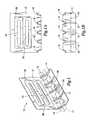
- FIG. 1is a perspective view of a first preferred embodiment of the bracket of the present invention
- FIG. 1Ais a cross-sectional view of the bracket of FIG. 1 taken along plane 19 in FIG. 1;
- FIG. 1Bis a cross-sectional view of the bracket of FIG. 1 taken along plane 17 in FIG. 1;
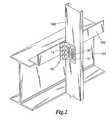
- FIG. 2is a perspective view of the bracket of FIG. 1 installed between a non-load bearing vertical stud and a horizontal structural I-beam so as to permit relative vertical movement between the two structures;
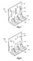
- FIG. 3is a perspective view of a second preferred embodiment of the bracket of the present invention.
- FIG. 4is a perspective view of a third preferred embodiment of the bracket of the present invention.
- FIG. 5is a perspective view of a fourth preferred embodiment of the bracket of the present invention.
- FIG. 6is a perspective view of a fifth preferred embodiment of the bracket of the present invention.
- FIG. 1illustrates generally at 10 a preferred embodiment of the bracket of the present invention.
- Bracket 10is preferably comprised of a stiff, durable, and thin material such as galvanized sheet steel.
- the bracket 10 of the present inventionis comprised of 14-gauge sheet steel having a thickness of about 0.07 inches.
- the thickness of the bracket 10may be of essentially any commercially available sheet steel regardless of gauge or thickness.
- the bracket 10includes a substantially planar first connector plate 14 and a substantially planar second connector plate 12 .
- the first connector plate 14 and the second connector plate 12are integrally joined so as to form a right angled juncture along corresponding edges of the first and second connector plates 14 , 12 , respectively.
- each of the triangular stiffener channels 16has a substantially U-shaped cross-section in a plane (designated as 17 in FIG. 1) parallel with the first connector plate 14 . See FIG. 1A. Additionally, each of the triangular stiffener channels 16 are also substantially U-shaped in cross-section in a plane (designated as 19 in FIG. 1) parallel with the second connector plate 12 . See FIG. 1B.
- the triangular stiffener channelsare provided to increase the rigidity and stiffener of the bracket 10 .
- a number of linear stiffener ridges or channels 18are provided (preferably in the first connector plate 14 ). More preferably, the linear stiffener channels 18 are disposed perpendicularly with the second connector plate 12 and extend from an end of a corresponding triangular stiffener channel 16 . Preferably, the triangular stiffener channel 16 with corresponding linear stiffener channels 18 , are spaced evenly across a length of the first connector plate 14 .
- the second connector plate 12is provided with one or more elongated slots 24 adapted to receive a fastener such as a shoulder screw.
- a fastenersuch as a shoulder screw.
- all of the elongated slots 24are substantially parallel with each other.
- each of the elongated slots 24may be disposed within a slot stiffener region 28 .
- Stiffener 28is preferably made by punching a channel around the region of each slot 24 . More preferably, the stiffener 28 comprises ⁇ fraction (1/16) ⁇ th inch round punched stiffener region.
- measurement indicia 26may also be provided along the length of each slot 24 .
- a plurality of substantially dimples 20may be provided to aid an installer with placement of fasteners to be inserted through the first connector panel 14 . Additionally, and again in an effort to assure the accurate placement of the fasteners through the first connector plate, a score mark 30 may be provided through the dimples 20 .
- the bracket 10 of the present inventionis shown in a portion of an assembled building structure.
- the first connector plate 14is shown being attached to a length of angled flange 102 which is attached to a load bearing structural I-beam 104 .
- the first connector plate 14may be attached to the load-bearing structural components in any suitable manner known in the art.
- a shoulder screw 32is provided to attach the second connector plate 12 to a non-load-bearing stud 100 .
- the shoulder screws 32provide substantially smooth slidable vertical movement relative to the second connector plate 12 and the non-load-bearing stud 100 .
- the bracket of the present inventionallows for vertical movement of the building structure without transferring compressive loads to the non-load bearing stud 100 or associated curtain wall.
- the exterior curtain wall studmay be attached to the supporting structure 104 while resisting horizontal forces and stresses caused by wind and other seismic loading. As a result, horizontal forces are resisted while the bracket 10 simultaneously provides for the vertical deflection of the primary building structure.
- an alternate embodiment 10 a of the bracketis shown having elongated slots 24 that are orientated perpendicularly with the juncture of first and second connector plates 14 , 12 , respectively.
- the bracket 10 amay be used to promote vertical deflection as described above.
- FIG. 10 byet an additional embodiment of the present invention 10 b, is depicted wherein one or more rows of holes 34 may be provided in place of the slots 24 of prior described embodiments.
- the holes 34are surrounded by a stiffener region 28 , much like the stiffener region 28 of the slotted embodiments of the invention.
- the embodiment of FIG. 10 bis advantageous in those situations where little or no vertical deflection is desired or likely to occur between the building components being connected with the bracket 10 b.
- bracket 10 cWith reference to FIG. 5, yet an additional embodiment of the bracket 10 c is shown with an alternate arrangement of slots 24 . Similar to the embodiment shown in FIG. 3, the embodiment shown in FIG. 5 is advantageous when the bracket 10 c is linking building components where freedom of movement is desired in a direction perpendicular with the right angle juncture of the bracket 10 c.
- FIG. 6An additional preferred embodiment of the bracket of the present invention is indicated generally by the reference numeral 10 d in FIG. 6. This embodiment is similar to that shown in FIG. 5 except that rows of holes 34 are provided instead of a plurality of slots 24 .
- all alternative embodimentsinclude the triangular stiffener channels 16 and a number of linear stiffener channels 18 to provide additional structural integrity.
Landscapes
- Engineering & Computer Science (AREA)
- Architecture (AREA)
- Physics & Mathematics (AREA)
- Electromagnetism (AREA)
- Civil Engineering (AREA)
- Structural Engineering (AREA)
- Joining Of Building Structures In Genera (AREA)
- Load-Bearing And Curtain Walls (AREA)
Abstract
Description
- This application is a continuation application of U.S. patent application Ser. No. 09/912,098 to Rahim Allagheband Zadeh, filed Jul. 24, 2001 and entitled Vertical Slide Clip and which claims the benefit of U.S. Provisional Patent Application Serial No. 60/220,420, filed Jul. 24, 2000.[0001]
- This invention relates to steel stud building systems, and, more particularly to brackets for connecting vertical steel wall studs to a building structure in a manner to permit relative vertical movement but prevent relative horizontal movement therebetween.[0002]
- Many industrial and commercial buildings and an increasing number of residential buildings are being constructed with steel stud wall systems for the various benefits obtained, such as reduced environmental concerns, fire safety and reduced susceptibility from warpage, insects, rust and rot.[0003]
- In the construction of buildings that may be subject to deflection due to wind or seismic forces, it is preferable to allow a degree of freedom of movement to reduce stress and to prevent fracture of connected parts. Ceilings often must rest directly on a structural frame or on load-bearing walls. Curtain walls, meaning walls such as partition walls which are not intended to support vertical loads, are best designed to not support vertical loads due to deflection of the primary load-bearing support structure of the building. Deflection is due to changes in the live loads.[0004]
- In addition to the occurrence of wind induced or seismic stress loading of a building structure, building component deflection is caused by changes in live or dead loading of the floor below or the ceiling above the curtain wall. However, typical prior construction systems have been designed so that all parts of a building are connected in a rigid and permanent fashion. When such a building structure is stressed, curtain walls tend to be damaged and the degree of damage sustained by other building parts is also increased.[0005]
- It is therefore an object of this invention to provide an apparatus for connecting a curtain wall to the primary structure so as to allow relative vertical movement therebetween while restricting relative horizontal movement.[0006]
- Additional objects, advantages and other novel features of the invention will be set forth in part in the description that follows and in part will become apparent to those skilled in the art upon examination of the following or may be learned with the practice of the invention as described and claimed herein.[0007]
- To achieve the foregoing and other objects, and in accordance with one aspect of the present invention, an improved bracket for connecting a pair of substantially perpendicular building components is provided. The bracket of the present invention advantageously allows relative vertical movement between the perpendicular building components. Preferably, the bracket includes a first connector plate joined at an edge and aligned with a second connector plate in substantially a right angle to form a right-angled juncture.[0008]
- A number of substantially triangular stiffener channels are disposed in the right-angled juncture each having a substantially U-shaped cross section. Additionally, a number of substantially linear stiffener channels are provided in the first connector plate that preferably each extend from a corresponding triangular stiffener channel.[0009]
- The second plate includes a number of elongated slots through which the plate may be connected with a shoulder crew or the like to a building component. The slot allows for vertical movement of the building structure without transferring compressive loads to the building component connected to the second plate, such as an exterior curtain wall. The first plate may be connected to structural framing of the building. When the structural framing of the building flexes downward, the bracket of the present invention allows for relative vertical movement thus relieving stresses and eliminating and resisting horizontal forces caused by wind or seismic loads.[0010]
- Still other objects of the present invention will become apparent to those skilled in this art from the following description and drawings wherein there is described and shown preferred embodiments of the invention. As will be realized, the invention is capable of other different embodiments, and its several details are capable of modification in various, obvious aspects all without departing from the invention. Accordingly, the drawings and descriptions will be regarded as illustrative in nature and not as restrictive.[0011]
- The accompanying drawings incorporated in and forming a part of the specification illustrate several aspects of the present invention, and together with the description and claims serve to explain the principles of the invention. In the accompanying drawings:[0012]
- FIG. 1 is a perspective view of a first preferred embodiment of the bracket of the present invention;[0013]
- FIG. 1A is a cross-sectional view of the bracket of FIG. 1 taken along[0014]
plane 19 in FIG. 1; - FIG. 1B is a cross-sectional view of the bracket of FIG. 1 taken along[0015]
plane 17 in FIG. 1; - FIG. 2 is a perspective view of the bracket of FIG. 1 installed between a non-load bearing vertical stud and a horizontal structural I-beam so as to permit relative vertical movement between the two structures;[0016]
- FIG. 3 is a perspective view of a second preferred embodiment of the bracket of the present invention;[0017]
- FIG. 4 is a perspective view of a third preferred embodiment of the bracket of the present invention;[0018]
- FIG. 5 is a perspective view of a fourth preferred embodiment of the bracket of the present invention; and[0019]
- FIG. 6 is a perspective view of a fifth preferred embodiment of the bracket of the present invention.[0020]
- Reference will not be made in detail to the present preferred embodiments of the invention, examples of which are illustrated in the accompanying drawings wherein like numerals indicate corresponding elements throughout the figures.[0021]
- FIG. 1 illustrates generally at[0022]10 a preferred embodiment of the bracket of the present invention. Bracket10 is preferably comprised of a stiff, durable, and thin material such as galvanized sheet steel. Preferably, the
bracket 10 of the present invention is comprised of 14-gauge sheet steel having a thickness of about 0.07 inches. Depending on the need of the given construction environment, it should be appreciated that the thickness of thebracket 10 may be of essentially any commercially available sheet steel regardless of gauge or thickness. As best seen in FIG. 1, thebracket 10 includes a substantially planarfirst connector plate 14 and a substantially planarsecond connector plate 12. As seen in FIG. 1, thefirst connector plate 14 and thesecond connector plate 12 are integrally joined so as to form a right angled juncture along corresponding edges of the first andsecond connector plates - According to an important aspect of the present invention, and as seen in FIG. 1, a plurality of substantially[0023]
triangular stiffener channels 16 are disposed at the intersection of the first andsecond connector plates 41,12, respectively. Preferably, each of thetriangular stiffener channels 16 has a substantially U-shaped cross-section in a plane (designated as17 in FIG. 1) parallel with thefirst connector plate 14. See FIG. 1A. Additionally, each of thetriangular stiffener channels 16 are also substantially U-shaped in cross-section in a plane (designated as19 in FIG. 1) parallel with thesecond connector plate 12. See FIG. 1B. Advantageously, the triangular stiffener channels are provided to increase the rigidity and stiffener of thebracket 10. - Additionally, and as seen in FIG. 1, a number of linear stiffener ridges or[0024]
channels 18 are provided (preferably in the first connector plate14). More preferably, thelinear stiffener channels 18 are disposed perpendicularly with thesecond connector plate 12 and extend from an end of a correspondingtriangular stiffener channel 16. Preferably, thetriangular stiffener channel 16 with correspondinglinear stiffener channels 18, are spaced evenly across a length of thefirst connector plate 14. - As can be seen in FIGS. 1 and 2, the[0025]
second connector plate 12 is provided with one or moreelongated slots 24 adapted to receive a fastener such as a shoulder screw. Preferably, all of theelongated slots 24 are substantially parallel with each other. In order to add additional rigidity to thebracket 10, each of theelongated slots 24 may be disposed within aslot stiffener region 28. Stiffener28 is preferably made by punching a channel around the region of eachslot 24. More preferably, thestiffener 28 comprises {fraction (1/16)}thinch round punched stiffener region. In order to aid an installer,measurement indicia 26 may also be provided along the length of eachslot 24. - Additionally, and as shown in FIG. 1, a plurality of substantially dimples[0026]20 may be provided to aid an installer with placement of fasteners to be inserted through the
first connector panel 14. Additionally, and again in an effort to assure the accurate placement of the fasteners through the first connector plate, ascore mark 30 may be provided through thedimples 20. - With reference to FIG. 2, the[0027]
bracket 10 of the present invention is shown in a portion of an assembled building structure. Thefirst connector plate 14 is shown being attached to a length ofangled flange 102 which is attached to a load bearing structural I-beam 104. Thefirst connector plate 14 may be attached to the load-bearing structural components in any suitable manner known in the art. - Preferably, a[0028]
shoulder screw 32 is provided to attach thesecond connector plate 12 to a non-load-bearing stud 100. Preferably, the shoulder screws32 provide substantially smooth slidable vertical movement relative to thesecond connector plate 12 and the non-load-bearing stud 100. Advantageously, when the structural framing (i.e., the structural I-beam104) is subject to loading and deflected downwardly, the bracket of the present invention allows for vertical movement of the building structure without transferring compressive loads to thenon-load bearing stud 100 or associated curtain wall. Accordingly, the exterior curtain wall stud may be attached to the supportingstructure 104 while resisting horizontal forces and stresses caused by wind and other seismic loading. As a result, horizontal forces are resisted while thebracket 10 simultaneously provides for the vertical deflection of the primary building structure. - With reference to FIG. 3, an[0029]
alternate embodiment 10aof the bracket is shown having elongatedslots 24 that are orientated perpendicularly with the juncture of first andsecond connector plates bracket 10amay be used to promote vertical deflection as described above. - As shown in FIG. 4, yet an additional embodiment of the[0030]
present invention 10b,is depicted wherein one or more rows ofholes 34 may be provided in place of theslots 24 of prior described embodiments. Preferably theholes 34 are surrounded by astiffener region 28, much like thestiffener region 28 of the slotted embodiments of the invention. The embodiment of FIG. 10bis advantageous in those situations where little or no vertical deflection is desired or likely to occur between the building components being connected with thebracket 10b. - With reference to FIG. 5, yet an additional embodiment of the[0031]
bracket 10cis shown with an alternate arrangement ofslots 24. Similar to the embodiment shown in FIG. 3, the embodiment shown in FIG. 5 is advantageous when thebracket 10cis linking building components where freedom of movement is desired in a direction perpendicular with the right angle juncture of thebracket 10c. - An additional preferred embodiment of the bracket of the present invention is indicated generally by the[0032]
reference numeral 10din FIG. 6. This embodiment is similar to that shown in FIG. 5 except that rows ofholes 34 are provided instead of a plurality ofslots 24. Preferably, all alternative embodiments include thetriangular stiffener channels 16 and a number oflinear stiffener channels 18 to provide additional structural integrity. - The foregoing description of a preferred embodiment of the invention has been presented for the purposes of illustration and description. It is not intended to be exhaustive or to limit the invention to the precise form disclosed. Obvious modifications or variations are possible in light of the above teachings. The embodiments were chosen and described in order to best illustrate the principles of the invention and their practical application to thereby enable one of ordinary skill in the art to best utilize the invention in various embodiments and with various modifications as are suited to the particular use contemplated. It is intended that the scope of the invention be defined by the claims attended hereto.[0033]
Claims (38)
Priority Applications (1)
| Application Number | Priority Date | Filing Date | Title |
|---|---|---|---|
| US10/732,753US7174690B2 (en) | 2000-07-24 | 2003-12-10 | Vertical slide clip |
Applications Claiming Priority (3)
| Application Number | Priority Date | Filing Date | Title |
|---|---|---|---|
| US22042000P | 2000-07-24 | 2000-07-24 | |
| US09/912,098US6688069B2 (en) | 2000-07-24 | 2001-07-24 | Vertical slide clip |
| US10/732,753US7174690B2 (en) | 2000-07-24 | 2003-12-10 | Vertical slide clip |
Related Parent Applications (1)
| Application Number | Title | Priority Date | Filing Date |
|---|---|---|---|
| US09/912,098ContinuationUS6688069B2 (en) | 2000-07-24 | 2001-07-24 | Vertical slide clip |
Publications (2)
| Publication Number | Publication Date |
|---|---|
| US20040118075A1true US20040118075A1 (en) | 2004-06-24 |
| US7174690B2 US7174690B2 (en) | 2007-02-13 |
Family
ID=26914874
Family Applications (2)
| Application Number | Title | Priority Date | Filing Date |
|---|---|---|---|
| US09/912,098Expired - LifetimeUS6688069B2 (en) | 2000-07-24 | 2001-07-24 | Vertical slide clip |
| US10/732,753Expired - LifetimeUS7174690B2 (en) | 2000-07-24 | 2003-12-10 | Vertical slide clip |
Family Applications Before (1)
| Application Number | Title | Priority Date | Filing Date |
|---|---|---|---|
| US09/912,098Expired - LifetimeUS6688069B2 (en) | 2000-07-24 | 2001-07-24 | Vertical slide clip |
Country Status (1)
| Country | Link |
|---|---|
| US (2) | US6688069B2 (en) |
Cited By (15)
| Publication number | Priority date | Publication date | Assignee | Title |
|---|---|---|---|---|
| US7293393B2 (en)* | 2004-01-27 | 2007-11-13 | Worthington Armstrong Venture | Perimeter clip for seismic ceilings |
| US20080115447A1 (en)* | 2004-08-12 | 2008-05-22 | Morse Michael G | Method of connecting post to joist |
| US20080289268A1 (en)* | 2007-05-21 | 2008-11-27 | Skidmore Owings & Merrill Llp | Seismic structural device |
| US20090173029A1 (en)* | 2008-01-07 | 2009-07-09 | Dennis Albert Socha | Polymeric acoustic isolator clip for isolating wallboard channels from frame member |
| WO2010009727A1 (en)* | 2008-07-21 | 2010-01-28 | Vkr Holding A/S | A mounting bracket for a roof penetrating structure |
| USD614943S1 (en)* | 2007-10-26 | 2010-05-04 | United States Gypsum Company | Acoustic isolator clip |
| USD644503S1 (en)* | 2010-05-13 | 2011-09-06 | James Anthony Crane | Steel stud deflection connector |
| WO2014053004A1 (en)* | 2012-10-02 | 2014-04-10 | Csr Building Products Limited | A connector |
| US20150159362A1 (en)* | 2006-12-22 | 2015-06-11 | Simpson Strong-Tie Company Inc. | Moment frame connector |
| US20170204599A1 (en)* | 2016-01-20 | 2017-07-20 | Larry Randall Daudet | Slide clip connector |
| US20180066424A1 (en)* | 2016-09-02 | 2018-03-08 | Simpson Strong-Tie Company, Inc. | Slip Clip |
| US10253507B1 (en)* | 2017-04-17 | 2019-04-09 | Henry H. Bilge | System for mounting wall panels to a wall |
| US10260240B1 (en)* | 2017-04-17 | 2019-04-16 | Henry H. Bilge | System for mounting wall panels to a wall |
| US10407917B1 (en) | 2017-04-17 | 2019-09-10 | Henry H. Bilge | System for mounting wall panels to a wall |
| US10787817B1 (en) | 2017-04-17 | 2020-09-29 | Henry H. Bilge | System for mounting adjustable covering panels to a wall |
Families Citing this family (70)
| Publication number | Priority date | Publication date | Assignee | Title |
|---|---|---|---|---|
| US6688069B2 (en)* | 2000-07-24 | 2004-02-10 | Unimast Incorporated | Vertical slide clip |
| US6920734B2 (en)* | 2000-08-31 | 2005-07-26 | Dietrich Industries, Inc. | Bridging system for off-module studs |
| US20040108444A1 (en)* | 2002-08-19 | 2004-06-10 | Cohen Jerome A. | Apparatus for making foundation walls having angled or arcuate contours |
| US6925768B2 (en)* | 2003-04-30 | 2005-08-09 | Hohmann & Barnard, Inc. | Folded wall anchor and surface-mounted anchoring |
| US20050005561A1 (en)* | 2003-07-11 | 2005-01-13 | Nucon Steel Corporation | Lateral and uplift resistance apparatus and methods for use in structural framing |
| US7673841B2 (en) | 2004-03-25 | 2010-03-09 | Cooper Technologies Company | Hangar bar for recessed luminaires with integral nail |
| US9696021B2 (en) | 2004-03-25 | 2017-07-04 | Cooper Technologies Company | Hanger bar for recessed luminaires |
| JP2005294124A (en)* | 2004-04-01 | 2005-10-20 | Seiko Epson Corp | ORGANIC ELECTROLUMINESCENT DEVICE, METHOD FOR PRODUCING ORGANIC ELECTROLUMINESCENT DEVICE, AND ELECTRONIC DEVICE |
| US20050279901A1 (en)* | 2004-06-21 | 2005-12-22 | Mccoy Kevin L | Stud securing system |
| US7478508B2 (en)* | 2004-08-16 | 2009-01-20 | Scafco Corporation | Mounting clip |
| US20060032183A1 (en)* | 2004-08-16 | 2006-02-16 | Peterson Neal L | Construction member |
| US7334372B2 (en)* | 2004-10-15 | 2008-02-26 | Simpson Strong-Tie Co., Inc. | Top flange hanger with strengthening embossment |
| US20070028555A1 (en)* | 2005-07-22 | 2007-02-08 | Michael Juenemann | Clip for steel stud walls |
| US8769887B2 (en)* | 2006-06-15 | 2014-07-08 | Ray A. Proffitt, Jr. | Hold down clip and wall system |
| US8234826B1 (en)* | 2006-06-15 | 2012-08-07 | Proffitt Jr Ray A | Hold down clip |
| US20080022624A1 (en)* | 2006-07-25 | 2008-01-31 | Hanson Courtney J | Joist support |
| US7640701B2 (en)* | 2006-11-10 | 2010-01-05 | Flannery Inc. | Deflection clip |
| US20090173036A1 (en)* | 2008-01-04 | 2009-07-09 | Hand Dennis L | Bracket for building components |
| US20090193750A1 (en)* | 2008-02-06 | 2009-08-06 | Roger Klima | Construction Clip For Joining Structural Infrastructure |
| US20100011697A1 (en)* | 2008-07-18 | 2010-01-21 | Hien Nguyen | Plantation Hurricane Tie |
| AU2008233436B2 (en)* | 2008-10-24 | 2012-12-06 | Mitek Holdings, Inc. | A bracket |
| USD652951S1 (en) | 2010-05-17 | 2012-01-24 | James Anthony Crane | Steel stud deflection connector |
| US8555592B2 (en)* | 2011-03-28 | 2013-10-15 | Larry Randall Daudet | Steel stud clip |
| US8800232B1 (en)* | 2011-04-04 | 2014-08-12 | LEK Innovations, LLC | Flange shear connection for precast concrete structures |
| JP5756355B2 (en)* | 2011-06-28 | 2015-07-29 | ニチハ株式会社 | Side wall prevention bracket for outer wall plate and outer wall construction structure using the same |
| FR2978809B1 (en)* | 2011-08-05 | 2013-09-06 | Safran | FASTENING AND METHOD AND TOOLING FOR ITS PRODUCTION |
| USD663020S1 (en)* | 2011-10-25 | 2012-07-03 | Thomas L Purnell | Mounting component for a temperature control system |
| US8590255B2 (en)* | 2011-10-26 | 2013-11-26 | Larry Randall Daudet | Bridging connector |
| US9109361B2 (en) | 2011-10-26 | 2015-08-18 | Simpson Strong-Tie Company, Inc. | Bracing bridging member |
| US8511032B2 (en) | 2011-12-06 | 2013-08-20 | The Steel Network, Inc. | Building structure having studs vertically movable with respect to a floor structure |
| US8882068B2 (en)* | 2012-02-26 | 2014-11-11 | Troy A. McGee | Boat transducer mounting apparatus |
| US9060607B1 (en) | 2012-10-17 | 2015-06-23 | Cooper Technologies Company | Hanger bar for recessed light fixture mounting |
| US9849497B2 (en) | 2013-03-13 | 2017-12-26 | Simpson Strong-Tie Company Inc. | Teardrop and offset notch bridging connector |
| USD692746S1 (en) | 2013-03-13 | 2013-11-05 | Clarkwestern Dietrich Building Systems Llc | Bridging clip |
| US11008753B2 (en) | 2013-03-13 | 2021-05-18 | Simpson Strong-Tie Company, Inc. | Corrugated bridging member |
| US9732520B2 (en) | 2013-03-17 | 2017-08-15 | Simpson Strong-Tie Company, Inc. | Inverted bridging connector |
| US8939418B2 (en) | 2013-04-05 | 2015-01-27 | Cooper Technologies Company | Adjustable hanger bar for luminaires |
| US9016024B1 (en) | 2013-11-27 | 2015-04-28 | Simpson Strong-Tie Company | Steel framing clip |
| USD730545S1 (en) | 2013-12-30 | 2015-05-26 | Simpson Strong-Tie Company | Joist and rafter connector |
| USD732708S1 (en) | 2013-12-30 | 2015-06-23 | Simpson Strong-Tie Company | Flared joist and rafter connector |
| US9091056B2 (en) | 2013-12-31 | 2015-07-28 | Simpson Strong-Tie Company, Inc. | Multipurpose concrete anchor clip |
| US9239131B1 (en) | 2015-06-05 | 2016-01-19 | Cooper Technologies Company | Adjustable hanger bars with detachment stop |
| US9732904B1 (en) | 2015-06-05 | 2017-08-15 | Cooper Technologies Company | Adjustable hanger bar assembly for luminaires |
| USD782902S1 (en)* | 2015-06-15 | 2017-04-04 | John Paulin | Deck rail connector |
| EP3334870B1 (en)* | 2015-08-13 | 2024-11-06 | The Steel Network, Inc. | Connector systems, assemblies, and methods |
| US9938709B2 (en)* | 2015-08-27 | 2018-04-10 | Simpson Strong-Tie Company, Inc. | Moment resisting kneewall connector |
| DE102017208381A1 (en)* | 2016-05-27 | 2017-11-30 | Ford Global Technologies, Llc | MOUNTING HOLDER FOR CONSOLE |
| USD815315S1 (en)* | 2016-09-08 | 2018-04-10 | Clarkwestern Dietrich Building Systems Llc | Slide clip with internal flanges |
| USD814905S1 (en) | 2016-09-08 | 2018-04-10 | Clarkwestern Dietrich Building Systems Llc | Slide clip with internal and external flanges |
| USD815313S1 (en)* | 2016-09-08 | 2018-04-10 | Clarkwestern Dietrich Building Systems Llc | Slide clip with external flanges |
| USD815316S1 (en)* | 2016-09-08 | 2018-04-10 | Clarkwestern Dietrich Building Systems Llc | Slide clip with internal flanges |
| USD817149S1 (en) | 2016-09-08 | 2018-05-08 | Clarkwestern Dietrich Building Systems Llc | Slide clip with internal and external flanges |
| USD815314S1 (en)* | 2016-09-08 | 2018-04-10 | Clarkwestern Dietrich Building Systems Llc | Slide clip with external flanges |
| CA2983144A1 (en) | 2016-10-21 | 2018-04-21 | Simpson Strong-Tie Company, Inc. | Improved slip clip connection |
| US10584837B2 (en) | 2016-10-28 | 2020-03-10 | Cordelia Lighting, Inc. | Bar hanger system for recessed fixtures |
| EP3372845B1 (en)* | 2017-03-08 | 2023-08-02 | SKF Aerospace France S.A.S. | Fitting with improved boss structure |
| USD798137S1 (en)* | 2017-03-09 | 2017-09-26 | Frank Locatell | Removable form tie |
| US10961704B2 (en)* | 2017-05-04 | 2021-03-30 | Simpson Strong-Tie Company Inc. | Drift track |
| USD862180S1 (en)* | 2018-04-14 | 2019-10-08 | G4 Products, LLC | Flower stripper |
| USD862281S1 (en)* | 2018-04-13 | 2019-10-08 | G4 Products, LLC | Flower stripper |
| USD839078S1 (en) | 2018-01-04 | 2019-01-29 | Clarkwestern Dietrich Building Systems Llc | Slide clip |
| USD902786S1 (en)* | 2019-05-09 | 2020-11-24 | Corey B. Johnson | Mounting rack |
| US11026374B2 (en)* | 2019-10-31 | 2021-06-08 | Kyle GUERRINI | Landscaping support component |
| JP1676928S (en)* | 2020-03-17 | 2021-01-18 | ||
| TWI707732B (en)* | 2020-03-31 | 2020-10-21 | 陳鴻銘 | A-shaped metal member and method for making the same |
| US11519179B2 (en)* | 2020-05-28 | 2022-12-06 | Rbd Holdings Llc | Attaching an assembled wall module to a building structure |
| USD959250S1 (en) | 2020-07-22 | 2022-08-02 | Clarkwestern Dietrich Building Systems Llc | Slide clip |
| US11692340B2 (en) | 2020-07-22 | 2023-07-04 | Clarkwestern Dietrich Building Systems Llc | Slide clip |
| USD959251S1 (en) | 2020-07-22 | 2022-08-02 | Clarkwestern Dietrich Building Systems Llc | Slide clip |
| USD915874S1 (en) | 2020-08-12 | 2021-04-13 | Frank Locatell | Removable form tie |
Citations (34)
| Publication number | Priority date | Publication date | Assignee | Title |
|---|---|---|---|---|
| US1486509A (en)* | 1923-03-16 | 1924-03-11 | John A Whittaker | Buck anchor |
| US1600794A (en)* | 1925-06-10 | 1926-09-21 | Payson Smith E | Retaining-valve anchor |
| US4060905A (en)* | 1976-08-19 | 1977-12-06 | Stanley Light | Gauge for mounting window-shade brackets |
| US4261593A (en)* | 1979-12-20 | 1981-04-14 | Lambert Corporation | Planting and fertilizing apparatus |
| US4433524A (en)* | 1981-06-19 | 1984-02-28 | Nostam, Inc. | Method and apparatus for slip-connector structural joint |
| US4691491A (en)* | 1985-03-20 | 1987-09-08 | Cladcolor Profiling Limited | Support systems |
| US4723747A (en)* | 1986-10-24 | 1988-02-09 | Capri Lighting | Bar hangers for recessed lighting fixtures |
| US4918893A (en)* | 1988-10-26 | 1990-04-24 | Vandenbroucke Jack Eric | One-piece stud attachment for supporting non-rigid insulation within a wall structure |
| US4920713A (en)* | 1989-10-18 | 1990-05-01 | V. Kann Rasmussen Industri A/S | Prefabricated window for installation in an inclined roof |
| US4932173A (en)* | 1988-07-21 | 1990-06-12 | Simpson Strong-Tie Company, Inc. | Truss clip |
| US5313752A (en)* | 1991-01-11 | 1994-05-24 | Fero Holdings Limited | Wall framing system |
| US5398902A (en)* | 1992-09-23 | 1995-03-21 | Crowe; Roger K. | Barn door flashing bracket assembly |
| US5454203A (en)* | 1990-08-30 | 1995-10-03 | Saf-T-Corp | Frame brace |
| US5467566A (en)* | 1991-10-28 | 1995-11-21 | Swartz & Kulpa, Structural Design And Engineering | Curtain wall clip |
| US5555694A (en)* | 1995-01-27 | 1996-09-17 | Simpson Strong-Tie Company, Inc. | Structural hanger |
| US5587555A (en)* | 1994-06-03 | 1996-12-24 | B-Line Systems, Inc. | Conductor holding device |
| US5640823A (en)* | 1995-06-30 | 1997-06-24 | Bergeron; Mark | Vertical movement clip for attaching a building member to a beam having a channel therein |
| US5664392A (en)* | 1996-04-08 | 1997-09-09 | Mucha; Brian A. | Deflection clip |
| US5670076A (en)* | 1994-08-04 | 1997-09-23 | Simpson Strong-Tie Company, Inc. | Reusable coupler for foundation anchor |
| US5720571A (en)* | 1994-12-22 | 1998-02-24 | Super Stud Building Products, Inc. | Deflection slide clip |
| US5732519A (en)* | 1996-07-30 | 1998-03-31 | Simpson Strong-Tie Company, Inc. | One piece foundation-to-frame connection |
| US5846018A (en)* | 1996-08-26 | 1998-12-08 | Super Stud Building Products, Inc. | Deflection slide clip |
| US5857306A (en)* | 1997-04-02 | 1999-01-12 | Mitek Holdings, Inc. | Truss-to-truss assemblies and connectors therefor |
| US5885024A (en)* | 1997-01-17 | 1999-03-23 | Zupan; Frank J. | Roof tile tie down clip |
| US5904023A (en)* | 1998-01-16 | 1999-05-18 | The Steel Network, Inc. | Steel stud stabilizing clip |
| US5906080A (en)* | 1997-05-15 | 1999-05-25 | Digirolamo; Edward R. | Bracket for interconnecting a building stud to primary structural components |
| US6009681A (en)* | 1998-05-01 | 2000-01-04 | Kozloff; Larry Alexander | Truss bracket |
| US6018923A (en)* | 1997-12-16 | 2000-02-01 | Usg Interiors, Inc. | Transition clip for drywall suspension grid |
| US6088982A (en)* | 1996-01-29 | 2000-07-18 | Hiesberger; Michael A. | System for connecting structural wall members |
| US6213679B1 (en)* | 1999-10-08 | 2001-04-10 | Super Stud Building Products, Inc. | Deflection slide clip |
| US20020062617A1 (en)* | 2000-11-29 | 2002-05-30 | The Steel Network, Inc. | Building member connector allowing bi-directional relative movement |
| US6688069B2 (en)* | 2000-07-24 | 2004-02-10 | Unimast Incorporated | Vertical slide clip |
| US6796099B1 (en)* | 2000-10-27 | 2004-09-28 | Simpson Strong-Tie Company, Inc. | Strap tie holder |
| US7065932B2 (en)* | 2003-10-06 | 2006-06-27 | Simpson Strong-Tie Company, Inc. | Top flange stud to plate tie |
- 2001
- 2001-07-24USUS09/912,098patent/US6688069B2/ennot_activeExpired - Lifetime
- 2003
- 2003-12-10USUS10/732,753patent/US7174690B2/ennot_activeExpired - Lifetime
Patent Citations (34)
| Publication number | Priority date | Publication date | Assignee | Title |
|---|---|---|---|---|
| US1486509A (en)* | 1923-03-16 | 1924-03-11 | John A Whittaker | Buck anchor |
| US1600794A (en)* | 1925-06-10 | 1926-09-21 | Payson Smith E | Retaining-valve anchor |
| US4060905A (en)* | 1976-08-19 | 1977-12-06 | Stanley Light | Gauge for mounting window-shade brackets |
| US4261593A (en)* | 1979-12-20 | 1981-04-14 | Lambert Corporation | Planting and fertilizing apparatus |
| US4433524A (en)* | 1981-06-19 | 1984-02-28 | Nostam, Inc. | Method and apparatus for slip-connector structural joint |
| US4691491A (en)* | 1985-03-20 | 1987-09-08 | Cladcolor Profiling Limited | Support systems |
| US4723747A (en)* | 1986-10-24 | 1988-02-09 | Capri Lighting | Bar hangers for recessed lighting fixtures |
| US4932173A (en)* | 1988-07-21 | 1990-06-12 | Simpson Strong-Tie Company, Inc. | Truss clip |
| US4918893A (en)* | 1988-10-26 | 1990-04-24 | Vandenbroucke Jack Eric | One-piece stud attachment for supporting non-rigid insulation within a wall structure |
| US4920713A (en)* | 1989-10-18 | 1990-05-01 | V. Kann Rasmussen Industri A/S | Prefabricated window for installation in an inclined roof |
| US5454203A (en)* | 1990-08-30 | 1995-10-03 | Saf-T-Corp | Frame brace |
| US5313752A (en)* | 1991-01-11 | 1994-05-24 | Fero Holdings Limited | Wall framing system |
| US5467566A (en)* | 1991-10-28 | 1995-11-21 | Swartz & Kulpa, Structural Design And Engineering | Curtain wall clip |
| US5398902A (en)* | 1992-09-23 | 1995-03-21 | Crowe; Roger K. | Barn door flashing bracket assembly |
| US5587555A (en)* | 1994-06-03 | 1996-12-24 | B-Line Systems, Inc. | Conductor holding device |
| US5670076A (en)* | 1994-08-04 | 1997-09-23 | Simpson Strong-Tie Company, Inc. | Reusable coupler for foundation anchor |
| US5720571A (en)* | 1994-12-22 | 1998-02-24 | Super Stud Building Products, Inc. | Deflection slide clip |
| US5555694A (en)* | 1995-01-27 | 1996-09-17 | Simpson Strong-Tie Company, Inc. | Structural hanger |
| US5640823A (en)* | 1995-06-30 | 1997-06-24 | Bergeron; Mark | Vertical movement clip for attaching a building member to a beam having a channel therein |
| US6088982A (en)* | 1996-01-29 | 2000-07-18 | Hiesberger; Michael A. | System for connecting structural wall members |
| US5664392A (en)* | 1996-04-08 | 1997-09-09 | Mucha; Brian A. | Deflection clip |
| US5732519A (en)* | 1996-07-30 | 1998-03-31 | Simpson Strong-Tie Company, Inc. | One piece foundation-to-frame connection |
| US5846018A (en)* | 1996-08-26 | 1998-12-08 | Super Stud Building Products, Inc. | Deflection slide clip |
| US5885024A (en)* | 1997-01-17 | 1999-03-23 | Zupan; Frank J. | Roof tile tie down clip |
| US5857306A (en)* | 1997-04-02 | 1999-01-12 | Mitek Holdings, Inc. | Truss-to-truss assemblies and connectors therefor |
| US5906080A (en)* | 1997-05-15 | 1999-05-25 | Digirolamo; Edward R. | Bracket for interconnecting a building stud to primary structural components |
| US6018923A (en)* | 1997-12-16 | 2000-02-01 | Usg Interiors, Inc. | Transition clip for drywall suspension grid |
| US5904023A (en)* | 1998-01-16 | 1999-05-18 | The Steel Network, Inc. | Steel stud stabilizing clip |
| US6009681A (en)* | 1998-05-01 | 2000-01-04 | Kozloff; Larry Alexander | Truss bracket |
| US6213679B1 (en)* | 1999-10-08 | 2001-04-10 | Super Stud Building Products, Inc. | Deflection slide clip |
| US6688069B2 (en)* | 2000-07-24 | 2004-02-10 | Unimast Incorporated | Vertical slide clip |
| US6796099B1 (en)* | 2000-10-27 | 2004-09-28 | Simpson Strong-Tie Company, Inc. | Strap tie holder |
| US20020062617A1 (en)* | 2000-11-29 | 2002-05-30 | The Steel Network, Inc. | Building member connector allowing bi-directional relative movement |
| US7065932B2 (en)* | 2003-10-06 | 2006-06-27 | Simpson Strong-Tie Company, Inc. | Top flange stud to plate tie |
Cited By (23)
| Publication number | Priority date | Publication date | Assignee | Title |
|---|---|---|---|---|
| US7293393B2 (en)* | 2004-01-27 | 2007-11-13 | Worthington Armstrong Venture | Perimeter clip for seismic ceilings |
| US20080115447A1 (en)* | 2004-08-12 | 2008-05-22 | Morse Michael G | Method of connecting post to joist |
| US11299880B2 (en)* | 2006-12-22 | 2022-04-12 | Simpson Strong-Tie Company Inc. | Moment frame connector |
| US20150159362A1 (en)* | 2006-12-22 | 2015-06-11 | Simpson Strong-Tie Company Inc. | Moment frame connector |
| US20080289268A1 (en)* | 2007-05-21 | 2008-11-27 | Skidmore Owings & Merrill Llp | Seismic structural device |
| US7647734B2 (en)* | 2007-05-21 | 2010-01-19 | Skidmore Owings & Merrill Llp | Seismic structural device |
| USD614943S1 (en)* | 2007-10-26 | 2010-05-04 | United States Gypsum Company | Acoustic isolator clip |
| US20090173029A1 (en)* | 2008-01-07 | 2009-07-09 | Dennis Albert Socha | Polymeric acoustic isolator clip for isolating wallboard channels from frame member |
| WO2010009727A1 (en)* | 2008-07-21 | 2010-01-28 | Vkr Holding A/S | A mounting bracket for a roof penetrating structure |
| USD644503S1 (en)* | 2010-05-13 | 2011-09-06 | James Anthony Crane | Steel stud deflection connector |
| AU2013327383B2 (en)* | 2012-10-02 | 2017-06-08 | Csr Building Products Limited | A connector |
| WO2014053004A1 (en)* | 2012-10-02 | 2014-04-10 | Csr Building Products Limited | A connector |
| AU2013327383C1 (en)* | 2012-10-02 | 2025-09-11 | Csr Building Products Limited | A connector |
| US20170204599A1 (en)* | 2016-01-20 | 2017-07-20 | Larry Randall Daudet | Slide clip connector |
| US20170204600A1 (en)* | 2016-01-20 | 2017-07-20 | Larry Randall Daudet | Drift Clip |
| US10087617B2 (en)* | 2016-01-20 | 2018-10-02 | Simpson Strong-Tie Company Inc. | Drift clip |
| US10273679B2 (en)* | 2016-01-20 | 2019-04-30 | Simpson Strong-Tie Company Inc. | Slide clip connector |
| US20180066424A1 (en)* | 2016-09-02 | 2018-03-08 | Simpson Strong-Tie Company, Inc. | Slip Clip |
| US10724229B2 (en)* | 2016-09-02 | 2020-07-28 | Simpson Strong-Tie Company, Inc. | Slip clip |
| US10253507B1 (en)* | 2017-04-17 | 2019-04-09 | Henry H. Bilge | System for mounting wall panels to a wall |
| US10260240B1 (en)* | 2017-04-17 | 2019-04-16 | Henry H. Bilge | System for mounting wall panels to a wall |
| US10407917B1 (en) | 2017-04-17 | 2019-09-10 | Henry H. Bilge | System for mounting wall panels to a wall |
| US10787817B1 (en) | 2017-04-17 | 2020-09-29 | Henry H. Bilge | System for mounting adjustable covering panels to a wall |
Also Published As
| Publication number | Publication date |
|---|---|
| US6688069B2 (en) | 2004-02-10 |
| US7174690B2 (en) | 2007-02-13 |
| US20020023405A1 (en) | 2002-02-28 |
Similar Documents
| Publication | Publication Date | Title |
|---|---|---|
| US7174690B2 (en) | Vertical slide clip | |
| US5906080A (en) | Bracket for interconnecting a building stud to primary structural components | |
| US6748705B2 (en) | Slotted M-track support | |
| AU2018210421B2 (en) | Drift clip | |
| US10724229B2 (en) | Slip clip | |
| US6301854B1 (en) | Floor joist and support system therefor | |
| US20180135293A1 (en) | Slip Clip Connection | |
| US11905700B2 (en) | Slide clip | |
| US20130174506A1 (en) | Thermally insulative spacer and methods involving use of same | |
| US20060191227A1 (en) | Slotted M-track beam structures and related wall assemblies | |
| US20220251838A1 (en) | Stiffener for Construction Elements | |
| US9790686B1 (en) | Triangular stud shaft wall system | |
| US12410617B2 (en) | Backing connector | |
| US20240295123A1 (en) | Z-shaped frame members, floor frames, and floors incorporating the same | |
| EP3571357A1 (en) | Drift clip | |
| AU1827701A (en) | Floor joist system and support member therefor |
Legal Events
| Date | Code | Title | Description |
|---|---|---|---|
| AS | Assignment | Owner name:UNIMAST INCORPORATED, ILLINOIS Free format text:ASSIGNMENT OF ASSIGNORS INTEREST;ASSIGNOR:ZADEH, RAHIM ALLAGHEBAND;REEL/FRAME:015240/0716 Effective date:20020612 | |
| AS | Assignment | Owner name:DIETRICH INDUSTRIES, INC., PENNSYLVANIA Free format text:MERGER;ASSIGNOR:UNIMAST INCORPORATED;REEL/FRAME:015462/0565 Effective date:20040531 | |
| AS | Assignment | Owner name:DIETRICH INDUSTRIES, INC., PENNSYLVANIA Free format text:MERGER;ASSIGNOR:UNIMAST INCORPORATED;REEL/FRAME:017858/0708 Effective date:20040531 | |
| STCF | Information on status: patent grant | Free format text:PATENTED CASE | |
| FPAY | Fee payment | Year of fee payment:4 | |
| AS | Assignment | Owner name:CLARKDIETRICH BUILDING SYSTEMS LLC, OHIO Free format text:ASSIGNMENT OF ASSIGNORS INTEREST;ASSIGNOR:DIETRICH INDUSTRIES, INC.;REEL/FRAME:026333/0453 Effective date:20110301 | |
| AS | Assignment | Owner name:CLARKWESTERN DIETRICH BUILDING SYSTEMS LLC, OHIO Free format text:CHANGE OF NAME;ASSIGNOR:CLARKDIETRICH BUILDING SYSTEMS LLC;REEL/FRAME:026348/0166 Effective date:20110209 | |
| AS | Assignment | Owner name:CLARKWESTERN DIETRICH BUILDING SYSTEMS LLC, OHIO Free format text:CORRECTIVE ASSIGNMENT TO CORRECT THE 02/09/2011 WAS INCORRECTLY ENTERED AS DATE OF EXECUTION FOR ASSIGNOR. CORRECT DATE OF EXECUTION IS 03/21/2011 PREVIOUSLY RECORDED ON REEL 026348 FRAME 0166. ASSIGNOR(S) HEREBY CONFIRMS THE CHANGE OF NAME;ASSIGNOR:CLARKDIETRICH BUILDING SYSTEMS LLC;REEL/FRAME:027188/0220 Effective date:20110321 | |
| FEPP | Fee payment procedure | Free format text:PAYOR NUMBER ASSIGNED (ORIGINAL EVENT CODE: ASPN); ENTITY STATUS OF PATENT OWNER: LARGE ENTITY | |
| FPAY | Fee payment | Year of fee payment:8 | |
| MAFP | Maintenance fee payment | Free format text:PAYMENT OF MAINTENANCE FEE, 12TH YEAR, LARGE ENTITY (ORIGINAL EVENT CODE: M1553); ENTITY STATUS OF PATENT OWNER: LARGE ENTITY Year of fee payment:12 |