US20040113626A1 - Method and apparatus for directional resistivity measurement while drilling - Google Patents
Method and apparatus for directional resistivity measurement while drillingDownload PDFInfo
- Publication number
- US20040113626A1 US20040113626A1US10/656,683US65668303AUS2004113626A1US 20040113626 A1US20040113626 A1US 20040113626A1US 65668303 AUS65668303 AUS 65668303AUS 2004113626 A1US2004113626 A1US 2004113626A1
- Authority
- US
- United States
- Prior art keywords
- tool
- magnetic field
- groove
- measuring
- grooves
- Prior art date
- Legal status (The legal status is an assumption and is not a legal conclusion. Google has not performed a legal analysis and makes no representation as to the accuracy of the status listed.)
- Granted
Links
- 238000005259measurementMethods0.000titleclaimsabstractdescription26
- 238000000034methodMethods0.000titleclaimsabstractdescription24
- 238000005553drillingMethods0.000titleclaimsabstractdescription16
- 230000015572biosynthetic processEffects0.000claimsabstractdescription27
- 229910000859α-FeInorganic materials0.000claimsabstractdescription9
- 239000000463materialSubstances0.000claimsabstractdescription8
- 230000005540biological transmissionEffects0.000claimsabstractdescription5
- 230000000694effectsEffects0.000claimsdescription5
- 238000005452bendingMethods0.000claimsdescription4
- 238000011835investigationMethods0.000abstractdescription2
- 239000010410layerSubstances0.000description36
- 238000005755formation reactionMethods0.000description21
- 230000006698inductionEffects0.000description12
- 238000013461designMethods0.000description7
- 230000005674electromagnetic inductionEffects0.000description5
- 230000009977dual effectEffects0.000description4
- 230000005672electromagnetic fieldEffects0.000description3
- 239000002184metalSubstances0.000description3
- 238000012986modificationMethods0.000description3
- 230000004048modificationEffects0.000description3
- 230000008859changeEffects0.000description2
- 239000003208petroleumSubstances0.000description2
- 239000004215Carbon black (E152)Substances0.000description1
- 238000006243chemical reactionMethods0.000description1
- 239000004020conductorSubstances0.000description1
- 230000008878couplingEffects0.000description1
- 238000010168coupling processMethods0.000description1
- 238000005859coupling reactionMethods0.000description1
- 230000001419dependent effectEffects0.000description1
- 238000005516engineering processMethods0.000description1
- 238000011156evaluationMethods0.000description1
- 239000012530fluidSubstances0.000description1
- 230000005484gravityEffects0.000description1
- 229930195733hydrocarbonNatural products0.000description1
- 150000002430hydrocarbonsChemical class0.000description1
- -1i.e.Substances0.000description1
- 230000035945sensitivityEffects0.000description1
- 239000002356single layerSubstances0.000description1
- 230000007480spreadingEffects0.000description1
- XLYOFNOQVPJJNP-UHFFFAOYSA-NwaterSubstancesOXLYOFNOQVPJJNP-UHFFFAOYSA-N0.000description1
Images


Classifications
- G—PHYSICS
- G01—MEASURING; TESTING
- G01V—GEOPHYSICS; GRAVITATIONAL MEASUREMENTS; DETECTING MASSES OR OBJECTS; TAGS
- G01V3/00—Electric or magnetic prospecting or detecting; Measuring magnetic field characteristics of the earth, e.g. declination, deviation
- G01V3/18—Electric or magnetic prospecting or detecting; Measuring magnetic field characteristics of the earth, e.g. declination, deviation specially adapted for well-logging
- G01V3/26—Electric or magnetic prospecting or detecting; Measuring magnetic field characteristics of the earth, e.g. declination, deviation specially adapted for well-logging operating with magnetic or electric fields produced or modified either by the surrounding earth formation or by the detecting device
- G01V3/28—Electric or magnetic prospecting or detecting; Measuring magnetic field characteristics of the earth, e.g. declination, deviation specially adapted for well-logging operating with magnetic or electric fields produced or modified either by the surrounding earth formation or by the detecting device using induction coils
Definitions
- the inventionis related generally to the field of electrical resistivity well logging methods. More specifically, the invention is related to a method and apparatus for providing a transverse coil and measuring cross-component magnetic fields in a downhole resisitivity tool.
- Electromagnetic induction and wave propagation logging toolsare commonly used for determination of electrical properties of formations surrounding a borehole. These logging tools give measurements of apparent resistivity (or conductivity) of the formation that, when properly interpreted, reasonably determine the petrophysical properties of the formation and the fluids therein.
- a typical electrical resistivity-measuring instrumentis an electromagnetic induction military well logging instrument such as described in U.S. Pat. No. 5,452,761 issued to Beard et al.
- the induction logging instrument described in the Beard '761 patentincludes a number of receiver coils spaced at various axial distances from a transmitter coil. Alternating current is passed through the transmitter coil, which induces alternating electromagnetic fields in the earth formations. Voltages, or measurements, are induced in the receiver coils as a result of electromagnetic induction phenomena related to the alternating electromagnetic fields. A continuous record of the voltages form curves, which are also referred to as induction logs.
- the induction instruments that are composed of multiple sets of receiver coilsare referred to as multi-array induction instruments. Every set of receiver coils together with the transmitter is named as a subarray.
- a multi-array inductionconsists of numerous subarrays and acquires measurements with all the subarrays.
- the present inventionprovides a method and apparatus for measuring cross-component providing magnetic field in a downhole resistivity tool for traversing a formation well bore measuring a property of interest in a formation adjacent the well bore, the down hole tool having a body with a longitudinal axis substantially aligned with a longitudinal axis of the well bore, the body having a external surface and a plurality of grooves cut in the external surface tool body and oriented perpendicular horizontally with respect to the antenna coil wire. For instance, if aalongitudinal axis of the tool body. A transverse coil whose coil plane contains the longitudinal axis of the tool body is used is used as a transmitter or receiver, the plurality of grooves are provided. An antenna is placed in the grooves for transmission or reception of a transverse magnetic field.
- Directional resistivity measurement while drillingprovides information on formation's resistivity azimuthal changes around the measuring device mounted close to the drill bit.
- One application of such measurementis in geosteering in which the azimuthal resistivity information helps determine the location of nearby zones (e.g., water zone or shale layers) relative to the drill bit., of different resistivities. This information helps keep the drill bit inside of target layers, i.e., hydrocarbon pay zones.
- Commercially available electromagnetic MWD devicese.g., MPR and EWR
- MPR and EWRhave been used to provide real-time formation resistivity properties for geosteering and formation evaluation. These tools, however, employ coaxial-coil transmitters and receivers and are lack of azimuthal resolution.
- the present inventionprovides a method and apparatus for measuring using a cross-component magnetic field in a multicomponent resistivity logging-while-drilling tool in a substantially horizontal borehole. Using data recorded with a single receiver or a plurality of receivers associated with a single transmitter or a plurality of transmitters with two different transmitter orientations, it is possible to determine the direction of resistive beds relative to the borehole.
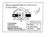
- FIG. 1shows a multi-component induction configuration of the invention for horizontal wells
- FIG. 2shows a configuration for a horizontal well application used to obtain results
- FIG. 3shows a configuration for a horizontal well application used to obtain results
- FIG. 4is an illustration of a downhole tool traversing a substantially horizontal horizontal deviated borehole in a three layer formation
- FIG. 5is an illustration of the magnetic field, in-phase phase real and quadrature quadrature imaginary parts for the ZX transmitter configuration in the three-layer formation shown in FIG. 4;
- FIG. 6is an illustration of the arrangement of horizontal grooves cut in tool body or collar to host a transverse coil (X-coil) and vertical grooves used to host a Z-coil;
- FIG. 7is a sectional view of the tool shown in FIG. 6 with wire and ferrite inserted in the gaps between the wire and the bottom of the grooves;
- FIG. 8is a top view of a general groove design showing multiple wires backed by a curved ferrite layer on top of the collar pipe metal;
- FIG. 9is an illustration of the equivalent coil system for the transverse loop shown in FIG. 7 wherein the small coils all have the same moment direction and therefore their contributions add to each other and the coil size is given by the gap between the wire an the groove bottom in FIG. 7;
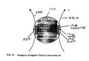
- FIG. 10is an illustration of the magnetic field reception by a transverse coil
- FIG. 11is an illustration of an arrangement of dual transmitters and dual receivers.
- FIG. 1shows the configuration of transmitter and receiver coils in a preferred embodiment of the 3DExplorerTM (3DEX) induction logging instrument of Baker Hughes.
- Three orthogonal transmitters 101 , 103 , and 105 that are referred to as the T x , T z , and T y transmittersare placed in the order shown.
- the three transmittersinduce magnetic fields in three spatial directions.
- the subscripts (x, y, z)indicate an orthogonal system substantially defined by the directions of the normals to the transmitters.
- the z-axisis chosen to be along the longitudinal axis of the tool, while the x-axis and y-axis are mutually perpendicular directions lying in the plane transverse to the axis.
- each transmitter 101 , 103 , and 105are associated receivers 111 , 113 , and 115 , referred to as the R x , R z , and R y receivers, aligned along the orthogonal system defined by the transmitter normals, placed in the order shown in FIG. 1.
- R x , R z , and R yare responsible for measuring the corresponding magnetic fields H xx , H zz , and H yy .
- the first indexindicates the direction of the transmitter and the second index indicates the direction of the receiver.
- the receivers R y and R zmeasure two cross-components, H xy and H xz , of the magnetic field produced by the T x transmitter ( 101 ).
- This embodiment of the inventionis operable in single frequency or multiple frequency modes.
- FIG. 1shows a sketch of a horizontal configuration for a multi-component induction tool.
- the orientation of the transmitters and receiversremain fixed with respect to the tool.
- the multi-component tool in horizontal configurationis sensitive to the anisotropic formation, tool location as well as the rotation of the tool around its axis. Only the H zz component is insensitive to tool rotation.
- the average 0.5*(H xx +H yy )is independent of tool rotation.
- the H zz and 0.5*(H xx +H yy ) measurementsare dependent on the formation and the tool location and thus an be used to determine the distance from the bed boundaries and for geo-steering the invention.
- the method of the present inventionmay be used with data acquired with a logging instrument conveyed on a wireline and also with data acquired using a measurements while drilling (MWD) apparatus conveyed on a drilling tubular such as a drill string or coiled tubing.
- MWDmeasurements while drilling
- this directional informationmay be used for controlling the direction of drilling and maintaining the position of the borehole relative to beds in the proximity of the borehole.
- Directional resistivitymay be measured using cross-component coils.
- One important cross-component combinationis a coaxial (Z) transmitter and an orthogonal (X) receiver.
- Zcoaxial
- Xorthogonal
- Such a combinationhas the capability of distinguishing targets located above or below, provided that the targets are within the depth of investigation of the device. This capability tells in which way the drill bit is approaching the geologic target.
- the challenge with the cross-component measurement for MWDis in building an X-coil to survive in the hostile drilling environment.
- the present inventionprovides a groove design for building an X-coil (used as transmitter or receiver) to meet the requirement. This design enables the present invention to radiate/detect transverse magnetic fields and protect the X-coil wire from damages posed by drilling operations.
- FIG. 4shows the magnetic field measured for a Z-transmitter 1716 and an X-receiver 1714 in a three-layer formation 1709 .
- the tool 1710is shown traversing a highly deviated borehole 1730 drilled into the formation 1709 .
- the upper 1712 and lower 1720 layersare 1 ohm-m and the middle 1718 layer in which the tool 1710 resides is 10 ohm-m.
- the transmitter 1716 and receiver 1714are aligned such that the tool axis is parallel to the bed boundaries 1705 and 1707 .
- observe that the magnetic field (imaginary part)changes sign as the tools moves from the upper layer boundary 1810 to the lower one 1812 . This sign change provides information for distinguishing layers that are above the tool from layers that are below the tool.
- a transverse coilcan be built by spreading a wire outside the collar surface on the opposite sides of the collar. The wire is then connected at the ends from inside the collar. To intercept signals there must be a gap between the wire and the collar surface at the bottom of the grooves. Because of the damage posed by drilling operations, the wire must be protected by mechanically strong and yet electrically nonconducting material.
- FIG. 4shows a design that meets these two requirements.
- a number of horizontal grooves 1914are cut on the surface of the collar. The grooves are spread out substantially along the collar axis direction. Holes 1917 are then placed beneath the collar surface 1710 in between the grooves 1914 (FIG. 5).
- An electrically insulated wire 1916is placed through the holes 1917 and grooves 1914 .
- a small gap 1713is left between the wire 1916 and the groove bottom 1915 .
- Ferrite materials 1918may be filled in the gap, as for a Z-coil design.
- the wires from the opposite sidesare connected to form a loop at the ends.
- a more general antenna designmay use multiple wires 1916 backed by a curved ferrite material 1918 layer on top of the metal pipe wall 1711 (FIG. 6). Because of its high conductivity, a metal drill collar 1710 is nearly a perfect conductor for operating frequencies from a few hundred kilohertz to a few megahertz. In reaction to an electromagnetic field, the collar will produce surface currents that mute the field inside the collar 1710 . As a result, the physical wire loop produces/receives no fields except in the groove areas 1914 . The effect of the physical wire loop can thus be replaced with small loops 2210 , as shown in FIG. 7. The areas of the small loops are given by the gaps between the wire 1916 and the groove bottom 1915 .
- FIG. 8sketches the magnetic field paths 2310 through the grooved area 1923 .
- the grooveshave open ends in the direction parallel to the field path.
- FIG. 9is an illustration of the equivalent coil system for the transverse loop shown in FIG. 7 wherein the small coils all have the same moment direction and therefore their contributions add to each other and the coil size is given by the gap between the wire an the groove bottom in FIG. 7.
- FIG. 10is an illustration of the magnetic field reception by a transverse coil; and
- FIG. 11is an illustration of an arrangement of dual transmitters and dual receivers.
- determining the azimuth of a nearby layermay require considering four possible different scenarios: (1) the tool is in a resistive layer overlying a conductive layer, (2) the tool is in a conductive layer overlying a resistive layer, (3) the tool is in a resistive layer underlying a conductive layer, and (4) the tool in a conductive layer underlying a resistive layer. Therefore, four independent measurements are made to uniquely distinguish a nearby layer. This is made possible by measuring both the in-phase and quadrature parts of the cross-component magnetic field. Measurement of in-phase and quadrature components also help eliminate ambiguity in determining the nearby be azimuth.
- Table 1lists the signature of both parts for the various scenarios. TABLE 1 The in-phase and magnetic field signatures for various tool positions and layer structures. Tool position Formation Inphase Quadrature Tool in upper layer Conductive layer above + ⁇ resistive layer Resistive layer above ⁇ ⁇ conductive layer Tool in lower layer Conductive layer above + + resistive layer Resistive layer above ⁇ + conductive layer
- the use of the cross-component magnetic field for determination of a nearby layer azimuthrelies on the transmitter and receiver coils being orthogonal to each other so that the direct coupling between the coils is absent. In reality, however, the tool may be bent due to the borehole curvature or decentralized due to gravity. Tool bending or eccentricity will destroy the coil orthogonality. In other words, the cross-coil measurement will contain the directly coupled field that may, depending on the severity of tool bending or eccentricity, destroy the usefulness of the cross-component field for azimuthal determination. To suppress tool bending or tool eccentricity effect, a second receiver may be used which is placed in between the first (outer) receiver and the transmitter. The measured in-phase and quadrature fields from the inner and outer receivers are then averaged according to the following formula to provide the final measurement
- H ra*H r in +H r out
- H ia*H i in +H i out
- H r in and H r outare the in-phase measurements of the inner and receivers, respectively
- H i in and H i outare the quadrature measurements of the two receivers respectively
- L in 3 and L out 3are the distances of the inner and outer receivers to the transmitter, respectively.
- the method of the present inventionis implemented as a set computer executable of instructions on a computer readable medium, comprising ROM, RAM, CD ROM, Flash or any other computer readable medium, now known or unknown that when executed cause a computer to implement the method of the present invention.
Landscapes
- Life Sciences & Earth Sciences (AREA)
- Engineering & Computer Science (AREA)
- Physics & Mathematics (AREA)
- Remote Sensing (AREA)
- Geology (AREA)
- Environmental & Geological Engineering (AREA)
- Electromagnetism (AREA)
- General Life Sciences & Earth Sciences (AREA)
- General Physics & Mathematics (AREA)
- Geophysics (AREA)
- Geophysics And Detection Of Objects (AREA)
- Measurement Of Resistance Or Impedance (AREA)
- Measuring Magnetic Variables (AREA)
Abstract
Description
- This patent application claims priority from U.S. Provisional Patent Application serial No. 60/408,615 filed on Sep. 6, 2002 entitled Method and Apparatus for the Use of Multicomponent Induction Tool and Cross Component Measurements for Geosteering and Formation Resistivity Data Interpretation in Horizontal Wells” by Tsili Wang, et al. which is incorporated herein by reference in its entirety.[0001]
- 1. Field of the Invention[0002]
- The invention is related generally to the field of electrical resistivity well logging methods. More specifically, the invention is related to a method and apparatus for providing a transverse coil and measuring cross-component magnetic fields in a downhole resisitivity tool.[0003]
- 2. Description of the Related Art[0004]
- Electromagnetic induction and wave propagation logging tools are commonly used for determination of electrical properties of formations surrounding a borehole. These logging tools give measurements of apparent resistivity (or conductivity) of the formation that, when properly interpreted, reasonably determine the petrophysical properties of the formation and the fluids therein.[0005]
- The physical principles of electromagnetic induction resistivity well logging are described, for example, in H. G. Doll,[0006]Introduction to Induction Logging and Application to Logging of Wells Drilled with Oil-Based Mud, Journal of Petroleum Technology, vol. 1, p.148, Society of Petroleum Engineers, Richardson, Tex. (1949). Many improvements and modifications to electromagnetic induction resistivity instruments have been devised since publication of the Doll reference, supra. Examples of such modifications and improvements can be found, for example, in U.S. Pat. No. 4,837,517; U.S. Pat. No. 5,157,605 issued to Chandler et al.; and U.S. Pat. No. 5,452,761 issued to Beard et al.
- A typical electrical resistivity-measuring instrument is an electromagnetic induction military well logging instrument such as described in U.S. Pat. No. 5,452,761 issued to Beard et al. The induction logging instrument described in the Beard '761 patent includes a number of receiver coils spaced at various axial distances from a transmitter coil. Alternating current is passed through the transmitter coil, which induces alternating electromagnetic fields in the earth formations. Voltages, or measurements, are induced in the receiver coils as a result of electromagnetic induction phenomena related to the alternating electromagnetic fields. A continuous record of the voltages form curves, which are also referred to as induction logs. The induction instruments that are composed of multiple sets of receiver coils are referred to as multi-array induction instruments. Every set of receiver coils together with the transmitter is named as a subarray. Hence, a multi-array induction consists of numerous subarrays and acquires measurements with all the subarrays.[0007]
- Conventional induction tools comprising only coaxial transmitter-receiver coil configurations do not have azimuthal sensitivity. Therefore, in a horizontal wellbore, the data do not contain information about directionality of the formation therefore, It is not possible to distinguish whether a layer is above or below the borehole from these data alone. There is a need to be able to determine directionality of the formation for use in, e.g., geosteering. This directionality knowledge can be obtained using a subset or all of the cross-components of the new multi-component induction tool to allow determination of directionality of the formation.[0008]
- The present invention provides a method and apparatus for measuring cross-component providing magnetic field in a downhole resistivity tool for traversing a formation well bore measuring a property of interest in a formation adjacent the well bore, the down hole tool having a body with a longitudinal axis substantially aligned with a longitudinal axis of the well bore, the body having a external surface and a plurality of grooves cut in the external surface tool body and oriented perpendicular horizontally with respect to the antenna coil wire. For instance, if aalongitudinal axis of the tool body. A transverse coil whose coil plane contains the longitudinal axis of the tool body is used is used as a transmitter or receiver, the plurality of grooves are provided. An antenna is placed in the grooves for transmission or reception of a transverse magnetic field.[0009]
- Directional resistivity measurement while drilling (MWD) provides information on formation's resistivity azimuthal changes around the measuring device mounted close to the drill bit. One application of such measurement is in geosteering in which the azimuthal resistivity information helps determine the location of nearby zones (e.g., water zone or shale layers) relative to the drill bit., of different resistivities. This information helps keep the drill bit inside of target layers, i.e., hydrocarbon pay zones. Commercially available electromagnetic MWD devices (e.g., MPR and EWR) have been used to provide real-time formation resistivity properties for geosteering and formation evaluation. These tools, however, employ coaxial-coil transmitters and receivers and are lack of azimuthal resolution. The present invention provides a method and apparatus for measuring using a cross-component magnetic field in a multicomponent resistivity logging-while-drilling tool in a substantially horizontal borehole. Using data recorded with a single receiver or a plurality of receivers associated with a single transmitter or a plurality of transmitters with two different transmitter orientations, it is possible to determine the direction of resistive beds relative to the borehole.[0010]
- The invention is best understood by reference to the following figures wherein like numbers refer to like components;[0011]
- FIG. 1 shows a multi-component induction configuration of the invention for horizontal wells;[0012]
- FIG. 2 shows a configuration for a horizontal well application used to obtain results;[0013]
- FIG. 3 shows a configuration for a horizontal well application used to obtain results;[0014]
- FIG. 4 is an illustration of a downhole tool traversing a substantially horizontal horizontal deviated borehole in a three layer formation;[0015]
- FIG. 5 is an illustration of the magnetic field, in-phase phase real and quadrature quadrature imaginary parts for the ZX transmitter configuration in the three-layer formation shown in FIG. 4;[0016]
- FIG. 6 is an illustration of the arrangement of horizontal grooves cut in tool body or collar to host a transverse coil (X-coil) and vertical grooves used to host a Z-coil;[0017]
- FIG. 7 is a sectional view of the tool shown in FIG. 6 with wire and ferrite inserted in the gaps between the wire and the bottom of the grooves;[0018]
- FIG. 8 is a top view of a general groove design showing multiple wires backed by a curved ferrite layer on top of the collar pipe metal;[0019]
- FIG. 9 is an illustration of the equivalent coil system for the transverse loop shown in FIG. 7 wherein the small coils all have the same moment direction and therefore their contributions add to each other and the coil size is given by the gap between the wire an the groove bottom in FIG. 7;[0020]
- FIG. 10 is an illustration of the magnetic field reception by a transverse coil; and[0021]
- FIG. 11 is an illustration of an arrangement of dual transmitters and dual receivers.[0022]
- FIG. 1 shows the configuration of transmitter and receiver coils in a preferred embodiment of the 3DExplorer™ (3DEX) induction logging instrument of Baker Hughes. Three orthogonal transmitters[0023]101,103, and105 that are referred to as the Tx, Tz, and Tytransmitters are placed in the order shown. The three transmitters induce magnetic fields in three spatial directions. The subscripts (x, y, z) indicate an orthogonal system substantially defined by the directions of the normals to the transmitters. The z-axis is chosen to be along the longitudinal axis of the tool, while the x-axis and y-axis are mutually perpendicular directions lying in the plane transverse to the axis. Corresponding to each transmitter101,103, and105 are associated receivers111,113, and115, referred to as the Rx, Rz, and Ryreceivers, aligned along the orthogonal system defined by the transmitter normals, placed in the order shown in FIG. 1. Rx, Rz, and Ryare responsible for measuring the corresponding magnetic fields Hxx, Hzz, and Hyy. Within this system for naming the magnetic fields, the first index indicates the direction of the transmitter and the second index indicates the direction of the receiver. In addition, the receivers Ryand Rz, measure two cross-components, Hxyand Hxz, of the magnetic field produced by the Txtransmitter (101). This embodiment of the invention is operable in single frequency or multiple frequency modes.
- FIG. 1 shows a sketch of a horizontal configuration for a multi-component induction tool. The orientation of the transmitters and receivers remain fixed with respect to the tool. The multi-component tool in horizontal configuration is sensitive to the anisotropic formation, tool location as well as the rotation of the tool around its axis. Only the H[0024]zzcomponent is insensitive to tool rotation. In horizontal configuration, the average 0.5*(Hxx+Hyy) is independent of tool rotation. The Hzzand 0.5*(Hxx+Hyy) measurements are dependent on the formation and the tool location and thus an be used to determine the distance from the bed boundaries and for geo-steering the invention.
- The method of the present invention may be used with data acquired with a logging instrument conveyed on a wireline and also with data acquired using a measurements while drilling (MWD) apparatus conveyed on a drilling tubular such as a drill string or coiled tubing. In particular, when used with MWD measurements, this directional information may be used for controlling the direction of drilling and maintaining the position of the borehole relative to beds in the proximity of the borehole.[0025]
- Directional resistivity may be measured using cross-component coils. One important cross-component combination is a coaxial (Z) transmitter and an orthogonal (X) receiver. Such a combination has the capability of distinguishing targets located above or below, provided that the targets are within the depth of investigation of the device. This capability tells in which way the drill bit is approaching the geologic target.[0026]
- The challenge with the cross-component measurement for MWD is in building an X-coil to survive in the hostile drilling environment. The present invention provides a groove design for building an X-coil (used as transmitter or receiver) to meet the requirement. This design enables the present invention to radiate/detect transverse magnetic fields and protect the X-coil wire from damages posed by drilling operations.[0027]
- To illustrate of the directionality of cross-component measurement, FIG. 4 shows the magnetic field measured for a Z-[0028]
transmitter 1716 and an X-receiver1714 in a three-layer formation 1709. Thetool 1710 is shown traversing a highly deviated borehole1730 drilled into theformation 1709. The upper1712 and lower1720 layers are 1 ohm-m and the middle1718 layer in which thetool 1710 resides is 10 ohm-m. Thetransmitter 1716 andreceiver 1714 are aligned such that the tool axis is parallel to thebed boundaries 1705 and1707. As shown in FIG. 3, observe that the magnetic field (imaginary part) changes sign as the tools moves from theupper layer boundary 1810 to the lower one1812. This sign change provides information for distinguishing layers that are above the tool from layers that are below the tool. - Directional measurement while drilling poses challenge for tool design because of the difficulty in putting a transverse coil. This invention proposes a method for building a transverse coil on a drill collar. The coil detects formation signals and meanwhile stands up to the stress of drilling operation.[0029]
- Conceptually, a transverse coil can be built by spreading a wire outside the collar surface on the opposite sides of the collar. The wire is then connected at the ends from inside the collar. To intercept signals there must be a gap between the wire and the collar surface at the bottom of the grooves. Because of the damage posed by drilling operations, the wire must be protected by mechanically strong and yet electrically nonconducting material.[0030]
- FIG. 4 shows a design that meets these two requirements. By analog to the[0031]
vertical grooves 1912 for hosting a coaxial (Z-) coil, a number ofhorizontal grooves 1914 are cut on the surface of the collar. The grooves are spread out substantially along the collar axis direction.Holes 1917 are then placed beneath thecollar surface 1710 in between the grooves1914 (FIG. 5). An electrically insulatedwire 1916 is placed through theholes 1917 andgrooves 1914. Within each groove1914 asmall gap 1713 is left between thewire 1916 and thegroove bottom 1915.Ferrite materials 1918 may be filled in the gap, as for a Z-coil design. The wires from the opposite sides are connected to form a loop at the ends. - A more general antenna design may use[0032]
multiple wires 1916 backed by acurved ferrite material 1918 layer on top of the metal pipe wall1711 (FIG. 6). Because of its high conductivity, ametal drill collar 1710 is nearly a perfect conductor for operating frequencies from a few hundred kilohertz to a few megahertz. In reaction to an electromagnetic field, the collar will produce surface currents that mute the field inside thecollar 1710. As a result, the physical wire loop produces/receives no fields except in thegroove areas 1914. The effect of the physical wire loop can thus be replaced withsmall loops 2210, as shown in FIG. 7. The areas of the small loops are given by the gaps between thewire 1916 and thegroove bottom 1915. The moments of the small loops all point the same direction and thus responses add to each other. FIG. 8 sketches themagnetic field paths 2310 through the groovedarea 1923. For the loop to radiate/receive fields requires that the grooves have open ends in the direction parallel to the field path. FIG. 9 is an illustration of the equivalent coil system for the transverse loop shown in FIG. 7 wherein the small coils all have the same moment direction and therefore their contributions add to each other and the coil size is given by the gap between the wire an the groove bottom in FIG. 7. FIG. 10 is an illustration of the magnetic field reception by a transverse coil; and FIG. 11 is an illustration of an arrangement of dual transmitters and dual receivers. - Even in the simplest case of two layers separated by a single layer boundary, determining the azimuth of a nearby layer may require considering four possible different scenarios: (1) the tool is in a resistive layer overlying a conductive layer, (2) the tool is in a conductive layer overlying a resistive layer, (3) the tool is in a resistive layer underlying a conductive layer, and (4) the tool in a conductive layer underlying a resistive layer. Therefore, four independent measurements are made to uniquely distinguish a nearby layer. This is made possible by measuring both the in-phase and quadrature parts of the cross-component magnetic field. Measurement of in-phase and quadrature components also help eliminate ambiguity in determining the nearby be azimuth. Table 1 lists the signature of both parts for the various scenarios.[0033]
TABLE 1 The in-phase and magnetic field signatures for various tool positions and layer structures. Tool position Formation Inphase Quadrature Tool in upper layer Conductive layer above + − resistive layer Resistive layer above − − conductive layer Tool in lower layer Conductive layer above + + resistive layer Resistive layer above − + conductive layer - The use of the cross-component magnetic field for determination of a nearby layer azimuth relies on the transmitter and receiver coils being orthogonal to each other so that the direct coupling between the coils is absent. In reality, however, the tool may be bent due to the borehole curvature or decentralized due to gravity. Tool bending or eccentricity will destroy the coil orthogonality. In other words, the cross-coil measurement will contain the directly coupled field that may, depending on the severity of tool bending or eccentricity, destroy the usefulness of the cross-component field for azimuthal determination. To suppress tool bending or tool eccentricity effect, a second receiver may be used which is placed in between the first (outer) receiver and the transmitter. The measured in-phase and quadrature fields from the inner and outer receivers are then averaged according to the following formula to provide the final measurement[0034]
- Hr=a*Hrin+Hrout
- Hi=a*Hiin+Hiout
- Where H[0035]rinand Hroutare the in-phase measurements of the inner and receivers, respectively, Hiinand Hioutare the quadrature measurements of the two receivers respectively, and a is a coefficient given by a=−Lin3/Lout3, where Lin3and Lout3are the distances of the inner and outer receivers to the transmitter, respectively.
- To make reliable measurements, the gains of the two receivers are known and kept constant. However, downhole temperature variations may cause the gains to change slightly. An uncorrected gain variation may destroy the balancing of the two receiver measurement as expressed by equations (1) and (2). To this end, a second transmitter (Z-directed) may be used which is placed symmetrically with respect to the center and on the opposite side of the two receivers. The measurement from each individual transmitter is then averaged to give the final measurement. The second transmitter also helps to remove a receiver gain drift effect.[0036]
- In another embodiment, the method of the present invention is implemented as a set computer executable of instructions on a computer readable medium, comprising ROM, RAM, CD ROM, Flash or any other computer readable medium, now known or unknown that when executed cause a computer to implement the method of the present invention.[0037]
- While the foregoing disclosure is directed to the preferred embodiments of the invention various modifications will be apparent to those skilled in the art. It is intended that all variations within the scope of the appended claims be embraced by the foregoing disclosure. Examples of the more important features of the invention have been summarized rather broadly in order that the detailed description thereof that follows may be better understood, and in order that the contributions to the art may be appreciated. There are, of course, additional features of the invention that will be described hereinafter and which will form the subject of the claims appended hereto.[0038]
Claims (26)
1. An apparatus for determining azimuth of a remote formation boundary by in a logging while drilling tool by measuring a transverse magnetic field in a down hole tool comprising:
a downhole resistivity tool for traversing a well bore measuring a property of interest in a formation adjacent to the well bore, the down hole tool having a body with a longitudinal axis substantially aligned with a longitudinal axis of the well bore, the body having a external surface;
a coil antenna placed near the external surface of the tool body; a groove cut in the external surface tool body and oriented horizontally with respect to the longitudinal axis of the tool body;
a transmitter comprising a transverse coil placed in the grooves for transmission or reception of a transverse magnetic field; and
a receiver coil antenna near the external surface of the tool body for reception of a magnetic field which is oriented substantially orthogonal with respect to the transmitter; and
grooves cut in the external surface of the tool body and oriented substantially perpendicularly with respect to the antenna wire.
2. The apparatus ofclaim 2 , further comprising:
a gap between the transverse coil and a bottom each groove in the plurality of grooves; and
a ferrite material placed in the gap.
3. The apparatus ofclaim 1 further comprising:
a plurality of receivers; and
a plurality of transmitters.
4. The apparatus ofclaim 1 , wherein the measurement further comprises:
an in phase and a quadrature component.
5. The apparatus ofclaim 1 , wherein the groove groove measurement further comprises:
a plurality of grooves.
6. The apparatus ofclaim 1 , further comprising:
a gap between the coil and the bottom of each groove under both transmitter and receiver coils; and a ferrite material placed in the gap.
7. The apparatus ofclaim 1 , wherein the groove further comprises:
a flat shape at a bottom of the groove.
8. The apparatus ofclaim 1 , wherein the groove further comprises:
a curved shape at a bottom of the groove.
9. A method for determining azimuth of a remote boundary by in a logging while drilling tool by measuring a transverse magnetic field in a down hole tool comprising:
measuring a property of interest in a formation adjacent the well bore, while traversing a well bore with a down hole tool, the down hole tool having a body with a longitudinal axis substantially aligned with a longitudinal axis of the well bore, the body having a external surface;
orienting horizontally with respect to the longitudinal axis of the tool body a groove cut in the external surface tool body and; and
placing a transmitter comprising a transverse coil placed in the grooves for transmission or reception of a transverse magnetic field; and
receiving a magnetic field in a receiver oriented orthogonal with respect to the transmitter.
10. The method ofclaim 9 , further comprising:
measuring a magnetic field with a single or plurality of receivers and a single or plurality of transmitters that are arranged substantially orthogonal with respect ot the receiver(s);
providing a gap between the transverse coil and a bottom each groove in the plurality of grooves; and
placing a ferrite material placed in the gap.
11. The method ofclaim 9 further comprising:
providing a plurality of receivers; and
providing a plurality of transmitters.
12. The method ofclaim 9 , further comprising:
measuring an in- phase and quadrature components of a magnetic field.
13. The method ofclaim 9 , further comprising:
processing the magnetic field data downhole from a plurality of receivers; and
processing the magnetic field data downhole from a plurality of transmitters; and
processing the magnetic field data downhole from a plurality of frequencies.
14. The method ofclaim 13 , further comprising:
measuring the magnetic field at multiple tool azimuthal angles.
15. The method ofclaim 9 , further comprising:
transmitting the measured and downhole-processed data uphole via a downhole data telemetry system;
measuring at a first frequency; and
measuring at a second frequency.
16. The method ofclaim 8 , wherein the groove further comprises:
providing a flat shape at a bottom of the groove.
17. The method ofclaim 9 , wherein the groove further comprises:
providing a curve shape at a bottom of the groove.
18. The method ofclaim 9 , further comprising:
processing the magnetic field data from a formation;
providing a plurality of receivers to reject tool- and borehole-related artifacts including but not limited to tool bending and tool eccentricity effects;
processing the magnetic field data from a plurality of transmitters to reject tool- and borehole-related artifacts including but not limited to borehole rugosity effects; and
processing the magnetic field data from a plurality of frequencies.
19. A computer readable medium containing instructions that when executed by a computer perform a method for determining azimuth of a remote boundary by a measured amplitude or phase component of an amplitude and phase component in a logging while drilling tool by measuring a cross-component transverse magnetic field in a down hole tool comprising:
measuring a property of interest in a formation adjacent the well bore, while traversing a well bore with a down hole tool, the down hole tool having a body with a longitudinal axis substantially aligned with a longitudinal axis of the well bore, the body having a external surface;
orienting horizontally with respect to the longitudinal axis of the tool body a groove cut in the external surface tool body and; and
placing a transmitter comprising a transverse coil placed in the grooves for transmission or reception of a transverse magnetic field; and
receiving a magnetic field in a receiver oriented orthogonal with respect to the transmitter.
20. The medium ofclaim 19 further comprising:
providing a gap between the transverse coil and a bottom each groove in the plurality of grooves; and
placing a ferrite material placed in the gap.
21. The medium ofclaim 19 further comprising:
providing a plurality of receivers; and
providing a plurality of transmitters.
22. The medium ofclaim 19 , further comprising:
measuring an in phase and quadrature component.
23. The medium ofclaim 19 , further comprising:
measuring at a first frequency; and
measuring at a second frequency.
24. The method ofclaim 19 , wherein the groove further comprises:
providing a flat shape at a bottom of the groove.
25. The apparatus ofclaim 19 , wherein the groove further comprises:
providing a curve shape at a bottom of the groove.
26. The method ofclaim 19 , further comprising:
providing a plurality of grooves.
Priority Applications (2)
| Application Number | Priority Date | Filing Date | Title |
|---|---|---|---|
| US10/656,683US7057392B2 (en) | 2002-09-06 | 2003-09-05 | Method and apparatus for directional resistivity measurement while drilling |
| US11/398,518US7414407B2 (en) | 2002-09-06 | 2006-04-05 | Method and apparatus for directional resistivity measurement while drilling |
Applications Claiming Priority (2)
| Application Number | Priority Date | Filing Date | Title |
|---|---|---|---|
| US40861502P | 2002-09-06 | 2002-09-06 | |
| US10/656,683US7057392B2 (en) | 2002-09-06 | 2003-09-05 | Method and apparatus for directional resistivity measurement while drilling |
Related Child Applications (1)
| Application Number | Title | Priority Date | Filing Date |
|---|---|---|---|
| US11/398,518ContinuationUS7414407B2 (en) | 2002-09-06 | 2006-04-05 | Method and apparatus for directional resistivity measurement while drilling |
Publications (2)
| Publication Number | Publication Date |
|---|---|
| US20040113626A1true US20040113626A1 (en) | 2004-06-17 |
| US7057392B2 US7057392B2 (en) | 2006-06-06 |
Family
ID=31978644
Family Applications (3)
| Application Number | Title | Priority Date | Filing Date |
|---|---|---|---|
| US10/388,871Expired - Fee RelatedUS6903553B2 (en) | 2002-09-06 | 2003-03-14 | Method and apparatus for a quadrupole transmitter for directionally sensitive induction tool |
| US10/656,683Expired - LifetimeUS7057392B2 (en) | 2002-09-06 | 2003-09-05 | Method and apparatus for directional resistivity measurement while drilling |
| US11/398,518Expired - LifetimeUS7414407B2 (en) | 2002-09-06 | 2006-04-05 | Method and apparatus for directional resistivity measurement while drilling |
Family Applications Before (1)
| Application Number | Title | Priority Date | Filing Date |
|---|---|---|---|
| US10/388,871Expired - Fee RelatedUS6903553B2 (en) | 2002-09-06 | 2003-03-14 | Method and apparatus for a quadrupole transmitter for directionally sensitive induction tool |
Family Applications After (1)
| Application Number | Title | Priority Date | Filing Date |
|---|---|---|---|
| US11/398,518Expired - LifetimeUS7414407B2 (en) | 2002-09-06 | 2006-04-05 | Method and apparatus for directional resistivity measurement while drilling |
Country Status (6)
| Country | Link |
|---|---|
| US (3) | US6903553B2 (en) |
| AU (1) | AU2003272283A1 (en) |
| CA (1) | CA2497888C (en) |
| GB (1) | GB2411243B (en) |
| NO (2) | NO337343B1 (en) |
| WO (1) | WO2004023164A1 (en) |
Cited By (25)
| Publication number | Priority date | Publication date | Assignee | Title |
|---|---|---|---|---|
| US20040183538A1 (en)* | 2003-03-19 | 2004-09-23 | Tilman Hanstein | Structure for electromagnetic induction well logging apparatus |
| US20060125479A1 (en)* | 2002-03-04 | 2006-06-15 | Baker Hughes Incorporated | Method for signal enhancement in azimuthal propagation resistivity while drilling |
| US20060186888A1 (en)* | 2002-09-06 | 2006-08-24 | Baker Hughes Incorporated | Method and apparatus for directional resistivity measurement while drilling |
| US20060192560A1 (en)* | 2005-02-21 | 2006-08-31 | Baker Hughes Incorporated | Well placement by use of differences in electrical anisotropy of different layers |
| US20070024286A1 (en)* | 2005-07-27 | 2007-02-01 | Baker Hughes Incorporated | Compensation for tool disposition in LWD resistivity measurements |
| US20070024285A1 (en)* | 2005-07-27 | 2007-02-01 | Baker Hughes Incorporated | Method of generating a deep resistivity image in LWD measurements |
| US7265649B1 (en) | 2007-02-19 | 2007-09-04 | Hall David R | Flexible inductive resistivity device |
| US7268555B1 (en) | 2006-04-06 | 2007-09-11 | Baker Hughes Incorporated | Correction of cross-component induction measurements for misalignment using comparison of the XY formation response |
| US20080068022A1 (en)* | 2006-09-20 | 2008-03-20 | Baker Hughes Incorporated | Resistivity tools with segmented azimuthally sensitive antennas and methods of making same |
| US20080074336A1 (en)* | 2006-09-25 | 2008-03-27 | Baker Hughes Incorporated | Resistivity tools with collocated antennas |
| US20080170466A1 (en)* | 2007-01-16 | 2008-07-17 | Precision Energy Services, Inc. | Reduction of tool eccentricity effects on acoustic measurements |
| US20090065254A1 (en)* | 2007-09-10 | 2009-03-12 | Baker Hughes Incorporated | Short Normal Electrical Measurement Using an Electromagnetic Transmitter |
| US20090160447A1 (en)* | 2007-02-19 | 2009-06-25 | Hall David R | Independently Excitable Resistivity Units |
| US20090188663A1 (en)* | 2007-02-19 | 2009-07-30 | Hall David R | Downhole Removable Cage with Circumferentially Disposed Instruments |
| US20090230969A1 (en)* | 2007-02-19 | 2009-09-17 | Hall David R | Downhole Acoustic Receiver with Canceling Element |
| US20100052689A1 (en)* | 2007-02-19 | 2010-03-04 | Hall David R | Magnetic Field Deflector in an Induction Resistivity Tool |
| EP2447738A1 (en)* | 2010-11-02 | 2012-05-02 | Smith International, Inc. | Method of correcting resistivity meaurements for tool bending effects |
| US20120109527A1 (en)* | 2010-09-17 | 2012-05-03 | Baker Hughes Incorporated | Apparatus and Methods for Drilling Wellbores by Ranging Existing Boreholes Using Induction Devices |
| CN103470249A (en)* | 2012-06-05 | 2013-12-25 | 刘策 | Apparatus and method for directional resistivity measurement while drilling using an antenna with a joint-coil structure |
| CN103726840A (en)* | 2013-03-05 | 2014-04-16 | 贝兹维仪器(苏州)有限公司 | Method and device used for measuring formation directed resistivity |
| US20160091628A1 (en)* | 2014-09-26 | 2016-03-31 | Chevron U.S.A. Inc. | Directional Antennas For Electromagnetic Mapping In a Borehole |
| CN107035364A (en)* | 2016-02-04 | 2017-08-11 | 中石化石油工程技术服务有限公司 | Electromagnetism scale method between a kind of well |
| US10386525B2 (en)* | 2015-03-31 | 2019-08-20 | Halliburton Energy Services, Inc. | Uniaxial anisotropy detection apparatus, systems, and methods |
| US20200102818A1 (en)* | 2017-01-27 | 2020-04-02 | Halliburton Energy Services, Inc. | Hybrid Axial and Radial Receiver Configurations for Electromagnetic Ranging Systems |
| US10989044B2 (en)* | 2016-10-03 | 2021-04-27 | Halliburton Energy Services, Inc. | Modeled transmitter and receiver coils with variable title angles for formation scanning |
Families Citing this family (59)
| Publication number | Priority date | Publication date | Assignee | Title |
|---|---|---|---|---|
| US7345487B2 (en)* | 2002-09-25 | 2008-03-18 | Halliburton Energy Services, Inc. | Method and system of controlling drilling direction using directionally sensitive resistivity readings |
| US7098858B2 (en)* | 2002-09-25 | 2006-08-29 | Halliburton Energy Services, Inc. | Ruggedized multi-layer printed circuit board based downhole antenna |
| US7093672B2 (en)* | 2003-02-11 | 2006-08-22 | Schlumberger Technology Corporation | Systems for deep resistivity while drilling for proactive geosteering |
| US7382135B2 (en)* | 2003-05-22 | 2008-06-03 | Schlumberger Technology Corporation | Directional electromagnetic wave resistivity apparatus and method |
| GB2417328B (en)* | 2003-05-22 | 2006-09-20 | Schlumberger Holdings | Methods of characterising earth formations |
| US7652478B2 (en)* | 2004-05-07 | 2010-01-26 | Baker Hughes Incorporated | Cross-component alignment measurement and calibration |
| US7408355B1 (en)* | 2004-05-07 | 2008-08-05 | Baker Hughes Incorporated | Borehole conductivity simulator verification and transverse coil balancing |
| US7319331B2 (en)* | 2004-05-07 | 2008-01-15 | Baker Hughes Incorporated | Two loop calibrator |
| US7471088B2 (en)* | 2004-12-13 | 2008-12-30 | Baker Hughes Incorporated | Elimination of the anisotropy effect in LWD azimuthal resistivity tool data |
| US7742008B2 (en)* | 2006-11-15 | 2010-06-22 | Baker Hughes Incorporated | Multipole antennae for logging-while-drilling resistivity measurements |
| DE112007001720T5 (en)* | 2007-01-29 | 2009-12-03 | Halliburton Energy Services, Inc., Houston | System and method with radially offset antennas for electromagnetic resistance logging |
| US7598742B2 (en)* | 2007-04-27 | 2009-10-06 | Snyder Jr Harold L | Externally guided and directed field induction resistivity tool |
| US8395388B2 (en)* | 2007-02-19 | 2013-03-12 | Schlumberger Technology Corporation | Circumferentially spaced magnetic field generating devices |
| US7759940B2 (en)* | 2007-04-04 | 2010-07-20 | Baker Hughes Incorporated | Mutual shielding of collocated induction coils in multi-component induction logging instruments |
| US7915895B2 (en)* | 2007-06-22 | 2011-03-29 | Baker Hughes Incorporated | Method of calibrating an azimuthal inductive cross-coil or tilted coil instrument |
| CN101382599B (en)* | 2007-09-03 | 2011-02-09 | 中国石油天然气集团公司 | Transient electromagnetical method for reservoir pore space anisotropy |
| CN101382070B (en)* | 2007-09-03 | 2012-01-11 | 中国石油天然气集团公司 | Electromagnetical method for dynamically monitoring oil reservoir injection-production |
| US7912648B2 (en)* | 2007-10-02 | 2011-03-22 | Baker Hughes Incorporated | Method and apparatus for imaging bed boundaries using azimuthal propagation resistivity measurements |
| US7839149B2 (en)* | 2008-01-11 | 2010-11-23 | Baker Hughes Incorporated | Multi-component resistivity logging tool with multiple antennas using common antenna grooves |
| US7707897B2 (en)* | 2008-05-27 | 2010-05-04 | Baker Hughes Incorporated | Method of measuring multiphase flow using a multi-stage flow meter |
| US8036830B2 (en) | 2008-05-29 | 2011-10-11 | Baker Hughes Incorporated | Resistivity imager in non-conductive mud for LWD and wireline applications |
| US8164339B2 (en)* | 2008-06-09 | 2012-04-24 | Baker Hughes Incorporated | Apparatus and system for geosteering and formation evaluation utilizing improved antennas |
| US8258790B2 (en)* | 2008-11-20 | 2012-09-04 | Baker Hughes Incorporated | Oscillator sensor for determining a property of an earth formation |
| US8786287B2 (en)* | 2009-03-04 | 2014-07-22 | Baker Hughes Incorporated | Collocated tri-axial induction sensors with segmented horizontal coils |
| US8207738B2 (en)* | 2009-03-24 | 2012-06-26 | Smith International Inc. | Non-planar antennae for directional resistivity logging |
| US8089268B2 (en)* | 2009-03-24 | 2012-01-03 | Smith International, Inc. | Apparatus and method for removing anisotropy effect from directional resistivity measurements |
| US8195400B2 (en)* | 2009-05-08 | 2012-06-05 | Smith International, Inc. | Directional resistivity imaging using harmonic representations |
| US7990153B2 (en)* | 2009-05-11 | 2011-08-02 | Smith International, Inc. | Compensated directional resistivity measurements |
| US8159227B2 (en)* | 2009-05-11 | 2012-04-17 | Smith International Inc. | Methods for making directional resistivity measurements |
| US8497673B2 (en)* | 2009-09-28 | 2013-07-30 | Schlumberger Technology Corporation | Directional resistivity antenna shield |
| US8466682B2 (en)* | 2009-09-29 | 2013-06-18 | Schlumberger Technology Corporation | Apparatus and method for downhole electromagnetic measurement while drilling |
| US9366780B2 (en) | 2009-10-08 | 2016-06-14 | Precision Energy Services, Inc. | Steerable magnetic dipole antenna for measurement while drilling applications |
| US9140817B2 (en)* | 2009-10-08 | 2015-09-22 | Precision Energy Services, Inc. | Steerable magnetic dipole antenna for measurement-while-drilling applications |
| US8271199B2 (en)* | 2009-12-31 | 2012-09-18 | Smith International, Inc. | Binning method for borehole imaging |
| US9423524B2 (en) | 2010-04-07 | 2016-08-23 | Baker Hughes Incorporated | Oil-based mud imager with a line source |
| US8600115B2 (en) | 2010-06-10 | 2013-12-03 | Schlumberger Technology Corporation | Borehole image reconstruction using inversion and tool spatial sensitivity functions |
| US9273517B2 (en) | 2010-08-19 | 2016-03-01 | Schlumberger Technology Corporation | Downhole closed-loop geosteering methodology |
| GB2500100B (en)* | 2010-08-26 | 2016-01-20 | Smith International | Apparatus and method for microresistivity imaging in nonconductive drilling fluid |
| US9043153B2 (en)* | 2011-03-15 | 2015-05-26 | Schlumberger Technology Corporation | Maximum depth of investigation of measurements in a formation |
| US8626446B2 (en) | 2011-04-01 | 2014-01-07 | Schlumberger Technology Corporation | Method of directional resistivity logging |
| EP3410160A1 (en)* | 2011-04-18 | 2018-12-05 | Halliburton Energy Services Inc. | Method for real-time downhole processing and detection of bed boundary for geosteering application |
| US20130113490A1 (en)* | 2011-08-30 | 2013-05-09 | Zhong Wang | Apparatus and method for directional resistivity measurement while drilling using incomplete circular antenna |
| CN102966348A (en)* | 2011-08-30 | 2013-03-13 | 王�忠 | Device and method for measurement while drilling of direction resistivity by using non-full circle antennas |
| CN102495431B (en)* | 2011-11-16 | 2014-05-21 | 中煤科工集团西安研究院有限公司 | Data processing method for carrying out static correction on transient electromagnetic data |
| US9062540B2 (en) | 2012-05-11 | 2015-06-23 | Baker Hughes Incorporated | Misalignment compensation for deep reading azimuthal propagation resistivity |
| US9091791B2 (en) | 2012-05-11 | 2015-07-28 | Baker Hughes Incorporated | Accounting for bending effect in deep azimuthal resistivity measurements using inversion |
| CN102841384A (en)* | 2012-08-03 | 2012-12-26 | 朱德兵 | Transient electromagnetic response signal horizontal component measuring method and observation device thereof |
| CA2895018C (en)* | 2012-12-31 | 2019-02-12 | Halliburton Energy Services, Inc. | Deep azimuthal system with multi-pole sensors |
| BR112015012050A2 (en) | 2012-12-31 | 2019-12-17 | Halliburton Energy Services Inc | formation imaging with multipole antennas |
| USD706179S1 (en)* | 2013-04-01 | 2014-06-03 | Westin Automotive Products, Inc. | Forged ring for a vehicle hitch assembly |
| US9389332B2 (en) | 2013-04-01 | 2016-07-12 | Oliden Technology, Llc | Method and tool for directional electromagnetic well logging |
| WO2014201297A2 (en) | 2013-06-12 | 2014-12-18 | Well Resolutions Technology | Apparatus and methods for making azimuthal resistivity measurements |
| CN103760614A (en)* | 2014-02-24 | 2014-04-30 | 中国科学院电子学研究所 | Transient electromagnetic forward modeling method applicable to irregular transmitted waveforms |
| WO2017082905A1 (en) | 2015-11-12 | 2017-05-18 | Halliburton Energy Services, Inc. | Multi-component induction logging data processing in non-circular boreholes |
| US11454102B2 (en) | 2016-05-11 | 2022-09-27 | Baker Hughes, LLC | Methods and systems for optimizing a drilling operation based on multiple formation measurements |
| US10087738B2 (en) | 2016-06-21 | 2018-10-02 | Probe Technology Services, Inc. | Electromagnetic casing inspection tool with azimuthal sensitivity |
| RU2673823C1 (en)* | 2017-07-31 | 2018-11-30 | Федеральное государственное бюджетное учреждение науки Институт геофизики им. Ю.П. Булашевича Уральского отделения Российской академии наук | Method for determining distance to medium border with different specific electrical resistances for geological steering of horizontal well bore |
| US20190137647A1 (en) | 2017-11-06 | 2019-05-09 | Weatherford Technology Holdings, Llc | Method and Apparatus for Formation Evaluation |
| CN108227012A (en)* | 2017-12-27 | 2018-06-29 | 湖南五维地质科技有限公司 | Obtain the device and method of the ground end data of set depth in target area |
Citations (7)
| Publication number | Priority date | Publication date | Assignee | Title |
|---|---|---|---|---|
| US4536714A (en)* | 1982-04-16 | 1985-08-20 | Schlumberger Technology Corporation | Shields for antennas of borehole logging devices |
| US4766384A (en)* | 1986-06-20 | 1988-08-23 | Schlumberger Technology Corp. | Well logging apparatus for determining dip, azimuth, and invaded zone conductivity |
| US5138263A (en)* | 1991-01-16 | 1992-08-11 | Teleco Oilfield Services Inc. | Electromagnetic formation evaluation tool |
| US5491488A (en)* | 1992-06-11 | 1996-02-13 | Baker Hughes Incorporated | Electromagnetic propagation tool using magnetic dipole antennas |
| US5530358A (en)* | 1994-01-25 | 1996-06-25 | Baker Hughes, Incorporated | Method and apparatus for measurement-while-drilling utilizing improved antennas |
| US6297639B1 (en)* | 1999-12-01 | 2001-10-02 | Schlumberger Technology Corporation | Method and apparatus for directional well logging with a shield having sloped slots |
| US6577129B1 (en)* | 2002-01-19 | 2003-06-10 | Precision Drilling Technology Services Group Inc. | Well logging system for determining directional resistivity using multiple transmitter-receiver groups focused with magnetic reluctance material |
Family Cites Families (7)
| Publication number | Priority date | Publication date | Assignee | Title |
|---|---|---|---|---|
| CH665682A5 (en)* | 1984-03-19 | 1988-05-31 | Prakla Seismos Gmbh | DRILL HOLE MEASURING DEVICE. |
| US4712070A (en)* | 1984-05-31 | 1987-12-08 | Schlumberger Technology Corporation | Apparatus for microinductive investigation of earth formations |
| US6100696A (en)* | 1998-01-09 | 2000-08-08 | Sinclair; Paul L. | Method and apparatus for directional measurement of subsurface electrical properties |
| US6191586B1 (en)* | 1998-06-10 | 2001-02-20 | Dresser Industries, Inc. | Method and apparatus for azimuthal electromagnetic well logging using shielded antennas |
| US6181138B1 (en)* | 1999-02-22 | 2001-01-30 | Halliburton Energy Services, Inc. | Directional resistivity measurements for azimuthal proximity detection of bed boundaries |
| US6509738B1 (en) | 2000-07-14 | 2003-01-21 | Schlumberger Technology Corporation | Electromagnetic induction well logging instrument having azimuthally sensitive response |
| US6903553B2 (en)* | 2002-09-06 | 2005-06-07 | Baker Hughes Incorporated | Method and apparatus for a quadrupole transmitter for directionally sensitive induction tool |
- 2003
- 2003-03-14USUS10/388,871patent/US6903553B2/ennot_activeExpired - Fee Related
- 2003-09-05CACA002497888Apatent/CA2497888C/ennot_activeExpired - Lifetime
- 2003-09-05USUS10/656,683patent/US7057392B2/ennot_activeExpired - Lifetime
- 2003-09-05AUAU2003272283Apatent/AU2003272283A1/ennot_activeAbandoned
- 2003-09-05GBGB0506676Apatent/GB2411243B/ennot_activeExpired - Lifetime
- 2003-09-05WOPCT/US2003/027957patent/WO2004023164A1/ennot_activeApplication Discontinuation
- 2005
- 2005-03-03NONO20051145Apatent/NO337343B1/ennot_activeIP Right Cessation
- 2006
- 2006-04-05USUS11/398,518patent/US7414407B2/ennot_activeExpired - Lifetime
- 2007
- 2007-05-10NONO20072420Apatent/NO337593B1/ennot_activeIP Right Cessation
Patent Citations (7)
| Publication number | Priority date | Publication date | Assignee | Title |
|---|---|---|---|---|
| US4536714A (en)* | 1982-04-16 | 1985-08-20 | Schlumberger Technology Corporation | Shields for antennas of borehole logging devices |
| US4766384A (en)* | 1986-06-20 | 1988-08-23 | Schlumberger Technology Corp. | Well logging apparatus for determining dip, azimuth, and invaded zone conductivity |
| US5138263A (en)* | 1991-01-16 | 1992-08-11 | Teleco Oilfield Services Inc. | Electromagnetic formation evaluation tool |
| US5491488A (en)* | 1992-06-11 | 1996-02-13 | Baker Hughes Incorporated | Electromagnetic propagation tool using magnetic dipole antennas |
| US5530358A (en)* | 1994-01-25 | 1996-06-25 | Baker Hughes, Incorporated | Method and apparatus for measurement-while-drilling utilizing improved antennas |
| US6297639B1 (en)* | 1999-12-01 | 2001-10-02 | Schlumberger Technology Corporation | Method and apparatus for directional well logging with a shield having sloped slots |
| US6577129B1 (en)* | 2002-01-19 | 2003-06-10 | Precision Drilling Technology Services Group Inc. | Well logging system for determining directional resistivity using multiple transmitter-receiver groups focused with magnetic reluctance material |
Cited By (52)
| Publication number | Priority date | Publication date | Assignee | Title |
|---|---|---|---|---|
| US7375530B2 (en) | 2002-03-04 | 2008-05-20 | Baker Hughes Incorporated | Method for signal enhancement in azimuthal propagation resistivity while drilling |
| US20060125479A1 (en)* | 2002-03-04 | 2006-06-15 | Baker Hughes Incorporated | Method for signal enhancement in azimuthal propagation resistivity while drilling |
| US20060186888A1 (en)* | 2002-09-06 | 2006-08-24 | Baker Hughes Incorporated | Method and apparatus for directional resistivity measurement while drilling |
| US7414407B2 (en)* | 2002-09-06 | 2008-08-19 | Baker Hughes Incorporated | Method and apparatus for directional resistivity measurement while drilling |
| US20040183538A1 (en)* | 2003-03-19 | 2004-09-23 | Tilman Hanstein | Structure for electromagnetic induction well logging apparatus |
| US20060192560A1 (en)* | 2005-02-21 | 2006-08-31 | Baker Hughes Incorporated | Well placement by use of differences in electrical anisotropy of different layers |
| GB2442401A (en)* | 2005-07-27 | 2008-04-02 | Baker Hughes Inc | Method of generating a deep resistivity image in LWD measurements |
| US20070024285A1 (en)* | 2005-07-27 | 2007-02-01 | Baker Hughes Incorporated | Method of generating a deep resistivity image in LWD measurements |
| US20070024286A1 (en)* | 2005-07-27 | 2007-02-01 | Baker Hughes Incorporated | Compensation for tool disposition in LWD resistivity measurements |
| WO2007015997A1 (en)* | 2005-07-27 | 2007-02-08 | Baker Hughes Incorporated | Method of generating a deep resistivity image in lwd measurements |
| GB2442401B (en)* | 2005-07-27 | 2010-06-09 | Baker Hughes Inc | Method of generating a deep resistivity image in LWD measurements |
| WO2007015992A1 (en)* | 2005-07-27 | 2007-02-08 | Baker Hughes Incorporated | Compensation for tool disposition in lwd resistivity measurements |
| US7483793B2 (en) | 2005-07-27 | 2009-01-27 | Baker Hughes Incorporated | Method of generating a deep resistivity image in LWD measurements |
| NO342148B1 (en)* | 2005-12-09 | 2018-04-03 | Baker Hughes A Ge Co Llc | Method for signal enhancement of azimuthal propagation resistivity during drilling |
| GB2446339B (en)* | 2005-12-09 | 2010-08-11 | Baker Hughes Inc | Method for signal enhancement in azimuthal propagation resistivity while drilling |
| WO2007070419A3 (en)* | 2005-12-09 | 2008-01-24 | Baker Hughes Inc | Method for signal enhancement in azimuthal propagation resistivity while drilling |
| NO20082470L (en)* | 2005-12-09 | 2008-07-07 | Baker Hughes A Ge Co Llc | Method for signal enhancement of azimuthal propagation resistivity during drilling |
| GB2446339A (en)* | 2005-12-09 | 2008-08-06 | Baker Hughes Inc | Method for signal enhancement in azimuthal propagation resistivity while drilling |
| US7268555B1 (en) | 2006-04-06 | 2007-09-11 | Baker Hughes Incorporated | Correction of cross-component induction measurements for misalignment using comparison of the XY formation response |
| RU2436131C2 (en)* | 2006-09-20 | 2011-12-10 | Бейкер Хьюз Инкорпорейтед | Electrical resistivity logging tools with carrier antennae, having azimuthal sensitivity and methods of using said tools |
| US7816921B2 (en) | 2006-09-20 | 2010-10-19 | Baker Hughes Incorporated | Resistivity tools with load-bearing azimuthally sensitive antennas and methods of using same |
| US7800372B2 (en)* | 2006-09-20 | 2010-09-21 | Baker Hughes Incorporated | Resistivity tools with segmented azimuthally sensitive antennas and methods of making same |
| US20080068022A1 (en)* | 2006-09-20 | 2008-03-20 | Baker Hughes Incorporated | Resistivity tools with segmented azimuthally sensitive antennas and methods of making same |
| RU2475645C2 (en)* | 2006-09-20 | 2013-02-20 | Бейкер Хьюз Инкорпорейтед | Resistivity tools with bearing segmented antennas with azimuth sensitivity and methods of their production |
| US20080074336A1 (en)* | 2006-09-25 | 2008-03-27 | Baker Hughes Incorporated | Resistivity tools with collocated antennas |
| US7663372B2 (en)* | 2006-09-25 | 2010-02-16 | Baker Hughes Incorporated | Resistivity tools with collocated antennas |
| US20080170466A1 (en)* | 2007-01-16 | 2008-07-17 | Precision Energy Services, Inc. | Reduction of tool eccentricity effects on acoustic measurements |
| US8194497B2 (en)* | 2007-01-16 | 2012-06-05 | Precision Energy Services, Inc. | Reduction of tool eccentricity effects on acoustic measurements |
| US20090188663A1 (en)* | 2007-02-19 | 2009-07-30 | Hall David R | Downhole Removable Cage with Circumferentially Disposed Instruments |
| US7265649B1 (en) | 2007-02-19 | 2007-09-04 | Hall David R | Flexible inductive resistivity device |
| US20090230969A1 (en)* | 2007-02-19 | 2009-09-17 | Hall David R | Downhole Acoustic Receiver with Canceling Element |
| US20090160447A1 (en)* | 2007-02-19 | 2009-06-25 | Hall David R | Independently Excitable Resistivity Units |
| US20100052689A1 (en)* | 2007-02-19 | 2010-03-04 | Hall David R | Magnetic Field Deflector in an Induction Resistivity Tool |
| US8198898B2 (en) | 2007-02-19 | 2012-06-12 | Schlumberger Technology Corporation | Downhole removable cage with circumferentially disposed instruments |
| US8299795B2 (en) | 2007-02-19 | 2012-10-30 | Schlumberger Technology Corporation | Independently excitable resistivity units |
| US7301429B1 (en) | 2007-02-19 | 2007-11-27 | Hall David R | Multiple frequency inductive resistivity device |
| US8436618B2 (en) | 2007-02-19 | 2013-05-07 | Schlumberger Technology Corporation | Magnetic field deflector in an induction resistivity tool |
| WO2009035979A1 (en)* | 2007-09-10 | 2009-03-19 | Baker Hughes Incorporated | Short normal electrical measurement using an electromagnetic transmitter |
| US20090066334A1 (en)* | 2007-09-10 | 2009-03-12 | Baker Hughes Incorporated | Short Normal Electrical Measurement Using an EM-Transmitter |
| US20090065254A1 (en)* | 2007-09-10 | 2009-03-12 | Baker Hughes Incorporated | Short Normal Electrical Measurement Using an Electromagnetic Transmitter |
| US20120109527A1 (en)* | 2010-09-17 | 2012-05-03 | Baker Hughes Incorporated | Apparatus and Methods for Drilling Wellbores by Ranging Existing Boreholes Using Induction Devices |
| EP2447738A1 (en)* | 2010-11-02 | 2012-05-02 | Smith International, Inc. | Method of correcting resistivity meaurements for tool bending effects |
| US8536871B2 (en) | 2010-11-02 | 2013-09-17 | Schlumberger Technology Corporation | Method of correcting resistivity measurements for toll bending effects |
| CN103470249A (en)* | 2012-06-05 | 2013-12-25 | 刘策 | Apparatus and method for directional resistivity measurement while drilling using an antenna with a joint-coil structure |
| CN103726840A (en)* | 2013-03-05 | 2014-04-16 | 贝兹维仪器(苏州)有限公司 | Method and device used for measuring formation directed resistivity |
| US20160091628A1 (en)* | 2014-09-26 | 2016-03-31 | Chevron U.S.A. Inc. | Directional Antennas For Electromagnetic Mapping In a Borehole |
| US9638827B2 (en)* | 2014-09-26 | 2017-05-02 | Los Alamos National Security, Llc | Directional antennas for electromagnetic mapping in a borehole |
| US10386525B2 (en)* | 2015-03-31 | 2019-08-20 | Halliburton Energy Services, Inc. | Uniaxial anisotropy detection apparatus, systems, and methods |
| CN107035364A (en)* | 2016-02-04 | 2017-08-11 | 中石化石油工程技术服务有限公司 | Electromagnetism scale method between a kind of well |
| US10989044B2 (en)* | 2016-10-03 | 2021-04-27 | Halliburton Energy Services, Inc. | Modeled transmitter and receiver coils with variable title angles for formation scanning |
| US20200102818A1 (en)* | 2017-01-27 | 2020-04-02 | Halliburton Energy Services, Inc. | Hybrid Axial and Radial Receiver Configurations for Electromagnetic Ranging Systems |
| US11125073B2 (en)* | 2017-01-27 | 2021-09-21 | Halliburton Energy Services, Inc. | Hybrid axial and radial receiver configurations for electromagnetic ranging systems |
Also Published As
| Publication number | Publication date |
|---|---|
| US7414407B2 (en) | 2008-08-19 |
| CA2497888A1 (en) | 2004-03-18 |
| NO20051145L (en) | 2005-06-03 |
| CA2497888C (en) | 2009-12-22 |
| NO20072420L (en) | 2005-06-03 |
| US6903553B2 (en) | 2005-06-07 |
| US20060186888A1 (en) | 2006-08-24 |
| US7057392B2 (en) | 2006-06-06 |
| GB0506676D0 (en) | 2005-05-11 |
| GB2411243A (en) | 2005-08-24 |
| GB2411243B (en) | 2006-03-22 |
| NO337343B1 (en) | 2016-03-21 |
| WO2004023164A1 (en) | 2004-03-18 |
| AU2003272283A1 (en) | 2004-03-29 |
| US20040046560A1 (en) | 2004-03-11 |
| NO337593B1 (en) | 2016-05-09 |
Similar Documents
| Publication | Publication Date | Title |
|---|---|---|
| US7057392B2 (en) | Method and apparatus for directional resistivity measurement while drilling | |
| US7239145B2 (en) | Subsurface electromagnetic measurements using cross-magnetic dipoles | |
| US6969994B2 (en) | Directional electromagnetic measurements insensitive to dip and anisotropy | |
| US7839149B2 (en) | Multi-component resistivity logging tool with multiple antennas using common antenna grooves | |
| US7612565B2 (en) | Apparatus and system for well placement and reservoir characterization | |
| US7778778B2 (en) | Correction of multi-component measurements for tool eccentricity in deviated wells | |
| US8237445B2 (en) | Octupole induction sensors for resistivity imaging in non-conductive muds | |
| US7629791B2 (en) | Method and apparatus for making multi-component measurements in deviated wells | |
| US9541666B2 (en) | Electromagnetic logging while drilling tool | |
| US6937022B2 (en) | Method and apparatus for a quadrupole transmitter for directionally sensitive induction tool | |
| US7554328B2 (en) | Method and apparatus for reducing borehole and eccentricity effects in multicomponent induction logging | |
| EP3497486B1 (en) | Determining a full electromagnetic coupling tensor using multiple antennas | |
| US10459110B2 (en) | Flexible conductive shield for downhole electromagnetic noise suppression |
Legal Events
| Date | Code | Title | Description |
|---|---|---|---|
| AS | Assignment | Owner name:BAKER HUGHES INCORPORATED, TEXAS Free format text:ASSIGNMENT OF ASSIGNORS INTEREST;ASSIGNORS:WANG, TSILI;TABAROVSKY, LEONTY;TCHAKAROV, BORIS;AND OTHERS;REEL/FRAME:014912/0708;SIGNING DATES FROM 20031218 TO 20040113 | |
| FEPP | Fee payment procedure | Free format text:PAYOR NUMBER ASSIGNED (ORIGINAL EVENT CODE: ASPN); ENTITY STATUS OF PATENT OWNER: LARGE ENTITY | |
| STCF | Information on status: patent grant | Free format text:PATENTED CASE | |
| FPAY | Fee payment | Year of fee payment:4 | |
| FPAY | Fee payment | Year of fee payment:8 | |
| MAFP | Maintenance fee payment | Free format text:PAYMENT OF MAINTENANCE FEE, 12TH YEAR, LARGE ENTITY (ORIGINAL EVENT CODE: M1553) Year of fee payment:12 |