US20040095183A1 - Clamping Circuit and Method for DMOS Drivers - Google Patents
Clamping Circuit and Method for DMOS DriversDownload PDFInfo
- Publication number
- US20040095183A1 US20040095183A1US10/249,398US24939803AUS2004095183A1US 20040095183 A1US20040095183 A1US 20040095183A1US 24939803 AUS24939803 AUS 24939803AUS 2004095183 A1US2004095183 A1US 2004095183A1
- Authority
- US
- United States
- Prior art keywords
- circuit
- current
- voltage
- low side
- transistor
- Prior art date
- Legal status (The legal status is an assumption and is not a legal conclusion. Google has not performed a legal analysis and makes no representation as to the accuracy of the status listed.)
- Granted
Links
- 238000000034methodMethods0.000titleclaimsabstractdescription12
- 230000001939inductive effectEffects0.000claimsabstractdescription41
- 230000001105regulatory effectEffects0.000claimsabstractdescription12
- 230000008901benefitEffects0.000description3
- 230000015556catabolic processEffects0.000description3
- 230000001133accelerationEffects0.000description2
- 238000010586diagramMethods0.000description2
- 230000001965increasing effectEffects0.000description2
- 238000012358sourcingMethods0.000description2
- 238000010276constructionMethods0.000description1
- 238000013500data storageMethods0.000description1
- 230000001419dependent effectEffects0.000description1
- 238000005086pumpingMethods0.000description1
- 230000000630rising effectEffects0.000description1
Images


Classifications
- H—ELECTRICITY
- H03—ELECTRONIC CIRCUITRY
- H03K—PULSE TECHNIQUE
- H03K17/00—Electronic switching or gating, i.e. not by contact-making and –breaking
- H03K17/08—Modifications for protecting switching circuit against overcurrent or overvoltage
- H03K17/081—Modifications for protecting switching circuit against overcurrent or overvoltage without feedback from the output circuit to the control circuit
- H03K17/0814—Modifications for protecting switching circuit against overcurrent or overvoltage without feedback from the output circuit to the control circuit by measures taken in the output circuit
- H03K17/08142—Modifications for protecting switching circuit against overcurrent or overvoltage without feedback from the output circuit to the control circuit by measures taken in the output circuit in field-effect transistor switches
- H—ELECTRICITY
- H03—ELECTRONIC CIRCUITRY
- H03K—PULSE TECHNIQUE
- H03K17/00—Electronic switching or gating, i.e. not by contact-making and –breaking
- H03K17/51—Electronic switching or gating, i.e. not by contact-making and –breaking characterised by the components used
- H03K17/56—Electronic switching or gating, i.e. not by contact-making and –breaking characterised by the components used by the use, as active elements, of semiconductor devices
- H03K17/687—Electronic switching or gating, i.e. not by contact-making and –breaking characterised by the components used by the use, as active elements, of semiconductor devices the devices being field-effect transistors
- H03K17/6871—Electronic switching or gating, i.e. not by contact-making and –breaking characterised by the components used by the use, as active elements, of semiconductor devices the devices being field-effect transistors the output circuit comprising more than one controlled field-effect transistor
- H03K17/6872—Electronic switching or gating, i.e. not by contact-making and –breaking characterised by the components used by the use, as active elements, of semiconductor devices the devices being field-effect transistors the output circuit comprising more than one controlled field-effect transistor using complementary field-effect transistors
Definitions
- This inventionrelates to improvements in H-bridge driver circuits for driving an inductive load, and more particularly to improvements in driver circuits of the type described that have circuits for diverting current from flowing through a high side driver transistor from the inductive load upon switching.
- the line loadgenerally consists of a resistive load, a current load, and a capacitive load.
- the current loadcan do nothing to absorb the current, and the resistive load can only do so at the price of increasing the voltage on the supply line. If enough capacitance is added to the system, then the capacitance can sink the inductor current, but this is a costly solution.
- Purchasers of drive electronics which are driving inductive loadswould benefit if the drive electronics were able to prevent the inductive current from dumping onto the main supply line.
- the solutionconceptually consists of a transconductance loop which regulates the voltage on a low side (LSD) gate to pull current from the inductive load to ground instead of allowing it to flow to the supply.
- LSDlow side
- the LSD gate being regulatedis on the same half H-bridge as the HSD gate whose body diode is supplying the path for the inductive load to pump up the supply line.
- an advantage of the inventionis that by using a transconductance loop approach, the clamping voltage can be made to depend only on a reference voltage, eliminating the dependence of the clamping voltage on transistor characteristics such as threshold voltage and current handling capability.
- the proposed inventionalso does not use a Zener diode so there is no dependence on the Zener diode breakdown voltage, which may be poorly controlled.
- Another advantage of the inventionis that by allowing the clamping voltage to depend only on a reference voltage, the designer can easily design the H-bridge drivers to clamp at any voltage necessary, without being limited to the available zener breakdown voltages and transistor threshold values.
- a circuitthat includes circuitry to operate an H-bridge configuration of FETs that are driving an inductive load.
- a half H-bridgeconsists of a two transistors: a high side transistor and a low side transistor.
- the high side transistorhas the supply voltage as its drain, the midpoint of the half H-bridge as its source, and an on-off control signal connected to its gate.
- the low side transistorhas the midpoint of the half H-bridge as its drain, the ground (or other sufficiently low voltage) as its source, and the invention herein-described connected to its gate.
- the inductorhas the midpoint of the half H-bridge connected to one of its terminals, and the second terminal is free to connect to any node as long as this second node can carry current.
- a circuitfor use in an electrical circuit that includes an inductive load which has a first side driven by an FET pair including a high side transistor connected in series with a low side transistor between a supply voltage and a reference potential.
- a second side of the inductive loadis connected to a circuit capable of carrying current to a reference potential.
- the high side transistoris of the type that has an associated body diode.
- the circuitincludes circuitry to operate the high side transistor and the circuit capable of carrying current to selectively allow a current to flow from the supply voltage through the high side transistor, the inductor, and the circuit capable of carrying current.
- a transconductance circuit loopis connected to control the circuit capable of carrying current to pull current from the inductive load to the reference potential when the inductive load sources current to the body diode sufficient to cause the voltage across the body diode to exceed a predetermined trip voltage.
- a transconductance loopregulates the voltage on the gate of one of the low side transistors to cause that same low side transistor to regulatedly conduct the inductor current away from the high side transistor to ground. It may include a sense circuit connected to sense the common voltage between a high side driver and a low side driver connected in series to provide a sensed voltage and a compare circuit connected to compare a trip voltage with the sensed voltage to provide an output current to a control element of the low side transistor to cause the low side transistor to conduct an amount of current related to a magnitude of the sensed voltage over the trip voltage.
- a methodfor operating an H-bridge power circuit that provides power to a load that includes an inductive component.
- the methodincludes sensing a voltage between a high side driver and a low side driver of the H-bridge power circuit and, if the voltage exceeds a predetermined level, diverting a current from the high side driver to the low side driver.
- the diversion of currentmay be accomplished by diverting the current from the high side driver to the low side driver in relation to a magnitude by which the voltage exceeds the predetermined level.
- a circuitfor protecting the upper transistors of an H-bridge circuit that provides power to a load that has an inductive component.
- the circuitincludes a transconductance circuit loop connected between one side of the inductive component and the gate of a low side transistor of the H-bridge.
- the transconductance circuitoperates to pull current from the inductive component to ground when the inductive load sources current to a body diode of the high side transistor.
- the transconductance loopcreates a regulated voltage to the gate of the low side transistor to cause the low side transistor to regulatedly conduct the current away from the inductor and the high side transistor to ground.
- an H-bridge power circuitfor providing power to a load that includes an inductive component.
- the H-bridge power circuitincludes means for sensing a voltage between a high side driver and a low side driver of the H-bridge power circuit, and means for diverting a current from the high side driver to the low side driver if the voltage exceeds a predetermined level.
- the means for divertingmay include means for diverting the current from the high side driver to the low side driver in relation to a magnitude by which the voltage exceeds the predetermined level.
- the means for divertingmay also include means for applying a bias to a control element of the low side driver in relation to a magnitude by which the voltage exceeds the predetermined level.
- the means for divertingmay also include means for developing a regulated bias current and applying the bias current to a control element of the low side driver.
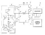
- FIG. 1is an electrical schematic diagram of a particular H-bridge driver circuit implementation which has a pair of current diverting circuits operatively associated therewith, in accordance with a preferred embodiment of the invention.
- FIG. 2is a graph of the current through a control transistor of a current diverting circuit, according to a preferred embodiment of the invention, vs. the voltage on the associated end of an inductive load driven by the H-bridge driver circuit.
- FIG. 3is an electrical schematic diagram of another embodiment of a particular H-bridge driver circuit implementation which has a pair of current diverting circuits operatively associated therewith, in accordance with a preferred embodiment of the invention.
- a driver circuit 10is shown in FIG. 1, in which an H-bridge driver 12 has two associated current diverting circuits 16 and 18 , according to a preferred embodiment of the invention.
- the H-bridge circuitis of standard construction, and includes two high side FET transistors 20 and 22 and two low side FET transistors 24 and 26 . It should be noted that a pair of circuits is not necessary in the realization of the principles of the invention. In the particular circuit illustrated, two drivers are employed. Generally speaking, if a PWM driver were driving an inductor with one terminal connected to the H-bridge and the second terminal connected to some voltage above ground, it is possible for the inductor current to kick back on the middle-point of the H-bridge and cause the voltage to increase.
- Transistors 20 and 24are connected in series between supply rail Vcc 28 and a reference voltage, or ground, rail 30 .
- Transistors 22 and 26are connected in series between supply rail Vcc 28 and a reference voltage, or ground, rail 30 .
- the transistors 20 , 22 , 24 , and 26may be, for example, high current DMOS transistors.
- a terminal of an inductive load 14is connected between the source of the high side driver and the drain of the low side driver in each respective leg.
- the inductive loadmay be, for example, a motor coil, such as a voice coil motor of the type that is typically used to selectively position the data transducers in mass data storage devices, or the like.
- the inductor load 14is shown as having only a pure inductive component, it will be understood that capacitive and resistive components may also exist; however, the inductive component is the principle contributor to the flyback current addressed by the current diverting circuit of the invention.
- a sequencer circuit 13is connected to the respective gates 21 , 23 , 25 , and 27 of the DMOS transistors 20 , 22 , 24 , and 26 to apply voltages thereto to cause currents selectively to flow through the inductor 14 in alternate directions in a manner as follows.
- voltagesmay be applied to the gates 21 and 27 of DMOS transistors 20 and 26 to turn them on to define a first current flow path from the Vcc rail 28 through the NMOS device 20 , the inductor 14 and NMOS device 26 to the reference potential, or ground, rail 30 . In the context of a VCM, this produces acceleration of the data transducer in a first direction.
- voltagesmay be applied to the gates 23 and 25 of DMOS transistors 22 and 24 to turn them on to define a first current flow path from the Vcc rail 28 through the NMOS device 22 , the inductor 14 and NMOS device 24 to the reference potential, or ground, rail 30 .
- thisproduces acceleration of the data transducer in a second direction.
- the low side driver transistor in an active current flow pathis turned off, the voltage on the lowside driver drain rapidly increases. The undesired current flow through the body diode of the upper drive transistor into the Vcc power supply may raise the Vcc power supply voltage and thereby damage components powered from the Vcc power supply.
- the potentially damaging flyback currentsare diverted through the low side driver transistors to the reference potential, or ground, rail 30 .
- current diverting circuits 16 and 18are provided to control the gates of low side NMOS driver transistors and 24 and 26 .
- the current diverting circuit 16which may be identically constructed to the current diverting circuit 18 , includes a diode connected NMOS transistor 32 , having its drain connected to node 33 to sense the voltage thereon and a connection to the gate 25 of NMOS transistor 24 to control the current therethrough in a manner below described.
- the current diverting circuit 18is similarly connected to the H-bridge 12 at node 35 on the opposite side of the inductor load and a connection to the gate 27 of NMOS transistor 26 to control the current therethrough in a manner below described.
- Two voltage-sensing transistorsare provided in the current diverting circuit 16 which includes PMOS input transistors 34 and 36 having a user controllable reference voltage, Vtrip, applied to the gates thereof.
- Vtripa user controllable reference voltage
- the transistors 34 and 36begin to conduct, as shown in the graph of FIG. 2, to which reference is now additionally made.
- the transistors 34 and 36are sometimes referred to herein as voltage-sensing transistors.
- Current flowing through transistor 36 to gate 25raises the voltage on gate 25 thus turning DMOS transistor 24 on.
- Current flowing through transistor 34flows into the input of a second current mirror pair comprised of transistors 38 and 42 .
- transistor 40may be sized to be 5 times larger than transistor 44 in order to provide 5 times the pull down current to transistor 24 to meet a slew rate requirement when turning off transistor 24 .
- transistor 36may be 4 times larger than transistor 34 allow fast rising voltages on node 33 to more quickly pull up on gate 25 .
- the graph in FIG. 2shows the current flowing through NMOS transistor 36 , denoted I 36 , as a function 49 of the voltage on node 33 , denoted V 33 . It can be seen that no current is delivered to the gate of NMOS transistor 24 until the voltage on node 33 exceeds the sum of the trip voltage, Vtrip plus the gate to source voltages of NMOS transistor 32 and PMOS transistor 36 . As the voltage on node 33 continues to rise above the threshold 50 , the current through PMOS transistor quadratically rises, which quadratically increases the current supplied to charge the gate of the lower NMOS driver transistor.
- the clamping voltagecan be made to depend only on the reference voltage, Vtrip, enabling the specific transistor characteristics to be properly matched.
- the voltage Vtripmay be generated in such a way as to be dependent on a reference voltage minus the voltage drop in a an NMOS transistor matched to NMOS transistor 32 and a PMOS transistor matched to PMOS transistors 34 and 36 .
- the bias current of the devices setting Vtripshould be made proportional to the current flowing through transistor 32 when the current diverting circuit 16 is effectively regulating the voltage at node 33 .
- the current diverting circuit 16 ′includes various claming devices to lower current consumption of the circuit when the clamps are inactive.
- a voltage “CLAMP”is applied on line 41 to the gates of NMOS transistors 43 , 45 , and 47 .
- Current, I, on line 45is injected into the drain of NMOS transistors 47 and the gates of NMOS transistors 40 and 44 .
- Clamp transistor 54is connected between the drains of transistors 42 and 44 and the ground rail 30
- clamp transistor 52is connected between the gates of transistors 40 and 44 and the ground rail 30 .
- transistor 47enables and disables the current mirror created by transistor pair 40 and 44 .
- the clampis on, transistor 47 is on, the current mirror is enabled, and the current, I, on line 41 is mirrored from transistor 44 to transistor 40 .
- the transistor 40does not pull the gate of the power DMOS transistor 24 down. Also, in this state, transistor 52 shuts off transistor 40 .
- transistors 47 , 42 and 44are off, and transistor 54 operates to prevent the drains of transistor 42 and 44 from floating.
- the current, Ipulls the gate of transistor 40 up, turning it on hard.
Landscapes
- Electronic Switches (AREA)
Abstract
Description
- This application claims priority from U.S. provisional patent application Ser. No. 60/319,705 filed Nov. 18, 2002.[0001]
- 1. Field of Invention[0002]
- This invention relates to improvements in H-bridge driver circuits for driving an inductive load, and more particularly to improvements in driver circuits of the type described that have circuits for diverting current from flowing through a high side driver transistor from the inductive load upon switching.[0003]
- 2. Relevant Background[0004]
- In systems in which an inductive load is being driven by an H-bridge configuration of FETs, there is the potential for the inductive load to source current through the high-side (HSD) FET body diode and onto the main supply line. This can result in increased supply voltage and damage to components not rated for such a voltage spike. The inductor current being directed to the main supply line must be absorbed by either the main supply or the line load.[0005]
- Unfortunately, many power supplies exhibit poor or no ability to sink the inductor current. The line load generally consists of a resistive load, a current load, and a capacitive load. The current load can do nothing to absorb the current, and the resistive load can only do so at the price of increasing the voltage on the supply line. If enough capacitance is added to the system, then the capacitance can sink the inductor current, but this is a costly solution. Purchasers of drive electronics which are driving inductive loads would benefit if the drive electronics were able to prevent the inductive current from dumping onto the main supply line.[0006]
- To address this problem in the past, others have used a zener diode from the middle of the H-bridge to the gate of the low side driver. When the inductor current pushes current into the middle of the H-bridge, the voltage increases, and if the voltage increases enough then the Zener diode breaks down and the low side driver is turned on to shunt the inductor current to ground. However, when using this method it is difficult to control the clamping level of the middle of the H-bridge because it is governed by the threshold voltage of the low side driver power device, the current handling ability of the low side driver, and the breakdown voltage of the zener diode. All three of these parameters can vary greatly from part to part. In some cases the magnitude of the variation for each parameter can be above 15%. This results in a poorly controlled clamping voltage. What is needed, therefore, is a circuit and method to protect the power supply and its components from damaging currents that may be produced by an inductive load in an H-bridge environment. This circuit and method should safely divert damaging currents away from the supply and into the ground in a well regulated manner such that the level at which the middle of the H-bridge is clamped is well controlled.[0007]
- Herein proposed is a solution in which the current from the inductive load is redirected in a regulated fashion to keep the current from pumping up the supply line voltage. The solution conceptually consists of a transconductance loop which regulates the voltage on a low side (LSD) gate to pull current from the inductive load to ground instead of allowing it to flow to the supply. The LSD gate being regulated is on the same half H-bridge as the HSD gate whose body diode is supplying the path for the inductive load to pump up the supply line.[0008]
- In light of the above, therefore, an advantage of the invention is that by using a transconductance loop approach, the clamping voltage can be made to depend only on a reference voltage, eliminating the dependence of the clamping voltage on transistor characteristics such as threshold voltage and current handling capability. The proposed invention also does not use a Zener diode so there is no dependence on the Zener diode breakdown voltage, which may be poorly controlled.[0009]
- Another advantage of the invention is that by allowing the clamping voltage to depend only on a reference voltage, the designer can easily design the H-bridge drivers to clamp at any voltage necessary, without being limited to the available zener breakdown voltages and transistor threshold values.[0010]
- Thus, a circuit is presented that includes circuitry to operate an H-bridge configuration of FETs that are driving an inductive load. A half H-bridge consists of a two transistors: a high side transistor and a low side transistor. The high side transistor has the supply voltage as its drain, the midpoint of the half H-bridge as its source, and an on-off control signal connected to its gate. The low side transistor has the midpoint of the half H-bridge as its drain, the ground (or other sufficiently low voltage) as its source, and the invention herein-described connected to its gate. The inductor has the midpoint of the half H-bridge connected to one of its terminals, and the second terminal is free to connect to any node as long as this second node can carry current.[0011]
- According to a broad aspect of the invention, a circuit is presented for use in an electrical circuit that includes an inductive load which has a first side driven by an FET pair including a high side transistor connected in series with a low side transistor between a supply voltage and a reference potential. A second side of the inductive load is connected to a circuit capable of carrying current to a reference potential. The high side transistor is of the type that has an associated body diode. The circuit includes circuitry to operate the high side transistor and the circuit capable of carrying current to selectively allow a current to flow from the supply voltage through the high side transistor, the inductor, and the circuit capable of carrying current. A transconductance circuit loop is connected to control the circuit capable of carrying current to pull current from the inductive load to the reference potential when the inductive load sources current to the body diode sufficient to cause the voltage across the body diode to exceed a predetermined trip voltage.[0012]
- A transconductance loop regulates the voltage on the gate of one of the low side transistors to cause that same low side transistor to regulatedly conduct the inductor current away from the high side transistor to ground. It may include a sense circuit connected to sense the common voltage between a high side driver and a low side driver connected in series to provide a sensed voltage and a compare circuit connected to compare a trip voltage with the sensed voltage to provide an output current to a control element of the low side transistor to cause the low side transistor to conduct an amount of current related to a magnitude of the sensed voltage over the trip voltage.[0013]
- According to another broad aspect of the invention, a method is presented for operating an H-bridge power circuit that provides power to a load that includes an inductive component. The method includes sensing a voltage between a high side driver and a low side driver of the H-bridge power circuit and, if the voltage exceeds a predetermined level, diverting a current from the high side driver to the low side driver. The diversion of current may be accomplished by diverting the current from the high side driver to the low side driver in relation to a magnitude by which the voltage exceeds the predetermined level.[0014]
- According to still another broad aspect of the invention, a circuit is provided for protecting the upper transistors of an H-bridge circuit that provides power to a load that has an inductive component. The circuit includes a transconductance circuit loop connected between one side of the inductive component and the gate of a low side transistor of the H-bridge. The transconductance circuit operates to pull current from the inductive component to ground when the inductive load sources current to a body diode of the high side transistor. The transconductance loop creates a regulated voltage to the gate of the low side transistor to cause the low side transistor to regulatedly conduct the current away from the inductor and the high side transistor to ground.[0015]
- According to still yet another broad aspect of the invention, an H-bridge power circuit is presented for providing power to a load that includes an inductive component. The H-bridge power circuit includes means for sensing a voltage between a high side driver and a low side driver of the H-bridge power circuit, and means for diverting a current from the high side driver to the low side driver if the voltage exceeds a predetermined level. The means for diverting may include means for diverting the current from the high side driver to the low side driver in relation to a magnitude by which the voltage exceeds the predetermined level. The means for diverting may also include means for applying a bias to a control element of the low side driver in relation to a magnitude by which the voltage exceeds the predetermined level. The means for diverting may also include means for developing a regulated bias current and applying the bias current to a control element of the low side driver.[0016]
- The invention is illustrated in the accompanying drawing.[0017]
- In the drawing, FIG. 1 is an electrical schematic diagram of a particular H-bridge driver circuit implementation which has a pair of current diverting circuits operatively associated therewith, in accordance with a preferred embodiment of the invention.[0018]
- FIG. 2 is a graph of the current through a control transistor of a current diverting circuit, according to a preferred embodiment of the invention, vs. the voltage on the associated end of an inductive load driven by the H-bridge driver circuit.[0019]
- And FIG. 3 is an electrical schematic diagram of another embodiment of a particular H-bridge driver circuit implementation which has a pair of current diverting circuits operatively associated therewith, in accordance with a preferred embodiment of the invention.[0020]
- In the various figures of the drawing, like reference numerals are used to refer to like or similar parts.[0021]
- A[0022]
driver circuit 10 is shown in FIG. 1, in which an H-bridge driver 12 has two associated currentdiverting circuits side FET transistors side FET transistors - [0023]
Transistors supply rail Vcc 28 and a reference voltage, or ground,rail 30.Transistors supply rail Vcc 28 and a reference voltage, or ground,rail 30. Thetransistors inductive load 14 is connected between the source of the high side driver and the drain of the low side driver in each respective leg. The inductive load may be, for example, a motor coil, such as a voice coil motor of the type that is typically used to selectively position the data transducers in mass data storage devices, or the like. Although theinductor load 14 is shown as having only a pure inductive component, it will be understood that capacitive and resistive components may also exist; however, the inductive component is the principle contributor to the flyback current addressed by the current diverting circuit of the invention. - A[0024]
sequencer circuit 13 is connected to therespective gates DMOS transistors inductor 14 in alternate directions in a manner as follows. Typically, voltages may be applied to thegates DMOS transistors Vcc rail 28 through theNMOS device 20, theinductor 14 andNMOS device 26 to the reference potential, or ground,rail 30. In the context of a VCM, this produces acceleration of the data transducer in a first direction. Alternatively, voltages may be applied to thegates DMOS transistors Vcc rail 28 through theNMOS device 22, theinductor 14 andNMOS device 24 to the reference potential, or ground,rail 30. In the context of the VCM, this produces acceleration of the data transducer in a second direction. As mentioned above, however, when the low side driver transistor in an active current flow path is turned off, the voltage on the lowside driver drain rapidly increases. The undesired current flow through the body diode of the upper drive transistor into the Vcc power supply may raise the Vcc power supply voltage and thereby damage components powered from the Vcc power supply. - According to a preferred embodiment of the invention, the potentially damaging flyback currents are diverted through the low side driver transistors to the reference potential, or ground,[0025]
rail 30. Thus, current divertingcircuits circuit 16, which may be identically constructed to the current divertingcircuit 18, includes a diode connectedNMOS transistor 32, having its drain connected tonode 33 to sense the voltage thereon and a connection to thegate 25 ofNMOS transistor 24 to control the current therethrough in a manner below described. The current divertingcircuit 18 is similarly connected to the H-bridge 12 atnode 35 on the opposite side of the inductor load and a connection to thegate 27 ofNMOS transistor 26 to control the current therethrough in a manner below described. - When a current is first flowing from[0026]
Vcc 28 throughhigh side FET 22, throughinductive load 14 and finally throughlow side FET 24, current divertingcircuit 16 is neither pulling current from, nor sourcing current to,gate 25 oftransistor 24. Other circuitry whose specific function is to control driver operation may control thegate 25 in any manner required by the drive system in the appropriate manner. When, however, the drive system requires thattransistor 24 be turned off, current divertingcircuit 16 is enabled to pull down ongate 25. This is effected by turning oncurrent source 46 and sourcing current into the input of a first current mirror pair comprised oftransistors transistor 44 causes a proportional current to flow into the drain oftransistor 40. The current flowing into the drain oftransistor 40 pulls down ongate 25 and turns offtransistor 24. - Two voltage-sensing transistors are provided in the current diverting[0027]
circuit 16 which includesPMOS input transistors node 33 exceeds the reference voltage Vtrip plus the gate-to-source voltages oftransistor 32 andtransistor transistors transistors transistor 36 togate 25 raises the voltage ongate 25 thus turningDMOS transistor 24 on. Current flowing throughtransistor 34 flows into the input of a second current mirror pair comprised oftransistors transistor 38 causes a proportional current to flow into the drain oftransistor 42. Current flowing into the drain oftransistor 42 reduces by an identical amount the amount of current fromcurrent source 46 that flows into the first current mirror pair comprised oftransistors gate 25 bytransistor 40. The current being sunk bytransistor 40 and the current sourced bytransistor 36 work to move the voltage ongate 25 in such a manner as to prevent the voltage onnode 33 from exceeding the desired voltage. The ratio of transistor pairs34 and36,38 and42, and44 and40 do not have to be unity and may in fact be chosen to meet various design criteria. For example,transistor 40 may be sized to be 5 times larger thantransistor 44 in order to provide 5 times the pull down current totransistor 24 to meet a slew rate requirement when turning offtransistor 24. As another example,transistor 36 may be 4 times larger thantransistor 34 allow fast rising voltages onnode 33 to more quickly pull up ongate 25. - The graph in FIG. 2 shows the current flowing through[0028]
NMOS transistor 36, denoted I36, as afunction 49 of the voltage onnode 33, denoted V33. It can be seen that no current is delivered to the gate ofNMOS transistor 24 until the voltage onnode 33 exceeds the sum of the trip voltage, Vtrip plus the gate to source voltages ofNMOS transistor 32 andPMOS transistor 36. As the voltage onnode 33 continues to rise above thethreshold 50, the current through PMOS transistor quadratically rises, which quadratically increases the current supplied to charge the gate of the lower NMOS driver transistor. - As a result, when the voltage on[0029]
node 33 increases, caused by theinductor 14, thecurrent diverter circuit 16 increases the conduction of the lowerNMOS driver transistor 24 to pull or divert to ground the current which otherwise would flow through the upperPMOS driver transistor 20 to the power supply. Thus, by using a transconductance loop approach, the clamping voltage can be made to depend only on the reference voltage, Vtrip, enabling the specific transistor characteristics to be properly matched. The voltage Vtrip may be generated in such a way as to be dependent on a reference voltage minus the voltage drop in a an NMOS transistor matched toNMOS transistor 32 and a PMOS transistor matched toPMOS transistors transistor 32 when the current divertingcircuit 16 is effectively regulating the voltage atnode 33. - With reference additionally now to FIG. 3, another current diverting[0030]
circuit embodiment 16′ shown. The current divertingcircuit 16′ includes various claming devices to lower current consumption of the circuit when the clamps are inactive. Thus, a voltage “CLAMP” is applied online 41 to the gates ofNMOS transistors line 45 is injected into the drain ofNMOS transistors 47 and the gates ofNMOS transistors Clamp transistor 54 is connected between the drains oftransistors ground rail 30, and clamptransistor 52 is connected between the gates oftransistors ground rail 30. - In operation,[0031]
transistor 47 enables and disables the current mirror created bytransistor pair transistor 47 is on, the current mirror is enabled, and the current, I, online 41 is mirrored fromtransistor 44 totransistor 40. In this state, thetransistor 40 does not pull the gate of thepower DMOS transistor 24 down. Also, in this state,transistor 52 shuts offtransistor 40. - However, when the clamp is off,[0032]
transistors transistor 54 operates to prevent the drains oftransistor transistor 40 up, turning it on hard. - Although the invention has been described and illustrated with a certain degree of particularity, it is understood that the present disclosure has been made only by way of example, and that numerous changes in the combination and arrangement of parts can be resorted to by those skilled in the art without departing from the spirit and scope of the invention, as hereinafter claimed.[0033]
Claims (20)
1. In an electrical circuit including an inductive load which has a first side driven by an FET pair including a high side transistor connected in series with a low side transistor between a supply voltage and a reference potential, wherein a second side of said inductive load is connected to a circuit capable of carrying current to a reference potential, and wherein said high side transistor has an associated body diode, a circuit comprising:
circuitry to operate said high side transistor and said circuit capable of carrying current to selectively allow a current to flow from said supply voltage through said high side transistor, said inductor, and said circuit capable of carrying current; and
a transconductance circuit loop connected to control said circuit capable of carrying current to pull current from said inductive load to said reference potential when said inductive load sources current to said body diode sufficient to cause the voltage across said body diode to exceed a predetermined trip voltage.
2. The circuit ofclaim 1 wherein said circuit capable of carrying current includes a second low side transistor and wherein said transconductance loop creates a regulated voltage to a gate of said second low side transistor to cause said second low side transistor to regulatedly conduct said current away from said inductor and said high side transistor to said reference potential.
3. The circuit ofclaim 1 wherein said transconductance loop comprises:
a sense circuit connected to sense a voltage on a node between said high side transistor and said low side transistor to provide a sensed voltage;
a compare circuit connected to compare said trip voltage with the sensed voltage to provide an output current to a control element of said circuit capable of carrying current to cause said circuit capable of carrying current to conduct amount of current related to a magnitude of said sensed voltage over said trip voltage.
4. The circuit ofclaim 1 wherein said compare circuit comprises a pair of FET compare devices having interconnected gates connected to said trip voltage, wherein said FET compare devices conduct when said sensed voltage exceeds said trip voltage plus a gate to source voltage drop on one of said FET compare devices.
5. The circuit ofclaim 4 further comprising a circuit for sinking a constant current from a gate of said low side driver transistor.
6. A method for operating an H-bridge power circuit that provides power to a load that includes an inductive component, comprising:
sensing a voltage between a high side driver and a low side driver of said H-bridge power circuit;
if said voltage exceeds a predetermined level, diverting a current from said high side driver to said low side driver.
7. The method ofclaim 6 wherein said diverting comprises diverting said current from said high side driver to said low side driver in relation to a magnitude by which said voltage exceeds said predetermined level.
8. The method ofclaim 6 wherein said diverting comprises applying a bias to a control element of said low side driver in relation to a magnitude by which said voltage exceeds said predetermined level.
9. The method ofclaim 6 wherein said diverting comprises developing a regulated bias current and applying said bias current to a control element of said low side driver.
10. The method ofclaim 6 further comprising said sensing and diverting are performed on opposite sides of said H-bridge.
11. A circuit for protecting upper transistors of an H-bridge circuit that provides power to a load that has an inductive component, comprising:
a transconductance circuit loop connected between one side of said inductive component and a gate of a low side transistor of said H-bridge, said transconductance circuit operating to pull current from said inductive component to ground when said inductive load sources current to a body diode of said high side transistor.
12. The circuit ofclaim 11 wherein said transconductance loop creates a regulated voltage to said gate of said low side transistor to cause said low side transistor to regulatedly conduct said current away from said inductor and said high side transistor to ground.
13. The circuit ofclaim 11 wherein said transconductance loop further comprises:
a sense circuit connected to sense a voltage on a node between said high side driver and said low side driver to provide a sensed voltage;
a compare circuit connected to compare a trip voltage with said sensed voltage to provide an output current to a control element of said low side transistor to cause said low side transistor to conduct amount of current related to a magnitude of said sensed voltage over said trip voltage.
14. The circuit ofclaim 11 wherein said compare circuit comprises a pair of FET compare devices having interconnected bases connected to a trip voltage, wherein said FET compare devices of said compare circuit conduct when said sensed voltage exceeds said trip voltage plus a gate to drain voltage drop on one of said FET compare devices.
15. The circuit ofclaim 14 further comprising a circuit for sinking a constant current from a gate of said low side driver transistor.
16. An H-bridge power circuit for providing power to a load that includes an inductive component, comprising:
means for sensing a voltage between a high side driver and a low side driver of said H-bridge power circuit;
and means for diverting a current from said high side driver to said low side driver if said voltage exceeds a predetermined level.
17. The H-bridge power circuit ofclaim 16 wherein said means for diverting comprises means for diverting said current from said high side driver to said low side driver in relation to a magnitude by which said voltage exceeds said predetermined level.
18. The H-bridge power circuit ofclaim 16 wherein said means for diverting comprises means for applying a bias to a control element of said low side driver in relation to a magnitude by which said voltage exceeds said predetermined level.
19. The H-bridge power circuit ofclaim 16 wherein said means for diverting comprises means for developing a regulated bias current and applying said bias current to a control element of said low side driver.
20. The H-bridge power circuit ofclaim 16 further comprising additional means for sensing and diverting on an opposite side of said H-bridge.
Priority Applications (1)
| Application Number | Priority Date | Filing Date | Title |
|---|---|---|---|
| US10/249,398US6798271B2 (en) | 2002-11-18 | 2003-04-04 | Clamping circuit and method for DMOS drivers |
Applications Claiming Priority (2)
| Application Number | Priority Date | Filing Date | Title |
|---|---|---|---|
| US31970502P | 2002-11-18 | 2002-11-18 | |
| US10/249,398US6798271B2 (en) | 2002-11-18 | 2003-04-04 | Clamping circuit and method for DMOS drivers |
Publications (2)
| Publication Number | Publication Date |
|---|---|
| US20040095183A1true US20040095183A1 (en) | 2004-05-20 |
| US6798271B2 US6798271B2 (en) | 2004-09-28 |
Family
ID=32302224
Family Applications (1)
| Application Number | Title | Priority Date | Filing Date |
|---|---|---|---|
| US10/249,398Expired - LifetimeUS6798271B2 (en) | 2002-11-18 | 2003-04-04 | Clamping circuit and method for DMOS drivers |
Country Status (1)
| Country | Link |
|---|---|
| US (1) | US6798271B2 (en) |
Cited By (21)
| Publication number | Priority date | Publication date | Assignee | Title |
|---|---|---|---|---|
| US20050007062A1 (en)* | 2003-07-09 | 2005-01-13 | Mehlhorn William L. | Switch assembly, electric machine having the switch assembly, and method of controlling the same |
| US20050117265A1 (en)* | 2003-12-01 | 2005-06-02 | Teggatz Rex M. | Current control via a variable voltage snubbing network |
| US7224135B1 (en)* | 2006-09-07 | 2007-05-29 | Acutechnology Semiconductor Inc. | Imposed current motor drive |
| US20090078965A1 (en)* | 2007-09-20 | 2009-03-26 | Briere Michael A | Individually controlled multiple iii-nitride half bridges |
| US20110133763A1 (en)* | 2008-07-21 | 2011-06-09 | Dspace Digital Signal Processing And Control Engineering Gmbh | Circuit for simulating an electrical load |
| US9328727B2 (en) | 2003-12-08 | 2016-05-03 | Pentair Water Pool And Spa, Inc. | Pump controller system and method |
| US9404500B2 (en) | 2004-08-26 | 2016-08-02 | Pentair Water Pool And Spa, Inc. | Control algorithm of variable speed pumping system |
| US9551344B2 (en) | 2004-08-26 | 2017-01-24 | Pentair Water Pool And Spa, Inc. | Anti-entrapment and anti-dead head function |
| US9556874B2 (en) | 2009-06-09 | 2017-01-31 | Pentair Flow Technologies, Llc | Method of controlling a pump and motor |
| US9568005B2 (en) | 2010-12-08 | 2017-02-14 | Pentair Water Pool And Spa, Inc. | Discharge vacuum relief valve for safety vacuum release system |
| US9726184B2 (en) | 2008-10-06 | 2017-08-08 | Pentair Water Pool And Spa, Inc. | Safety vacuum release system |
| US9777733B2 (en) | 2004-08-26 | 2017-10-03 | Pentair Water Pool And Spa, Inc. | Flow control |
| US9885360B2 (en) | 2012-10-25 | 2018-02-06 | Pentair Flow Technologies, Llc | Battery backup sump pump systems and methods |
| US9932984B2 (en) | 2004-08-26 | 2018-04-03 | Pentair Water Pool And Spa, Inc. | Pumping system with power optimization |
| US10240604B2 (en) | 2004-08-26 | 2019-03-26 | Pentair Water Pool And Spa, Inc. | Pumping system with housing and user interface |
| US10355688B2 (en)* | 2017-12-06 | 2019-07-16 | Silanna Asia Pte Ltd | Controlled current manipulation for regenerative charging of gate capacitance |
| US10731655B2 (en) | 2004-08-26 | 2020-08-04 | Pentair Water Pool And Spa, Inc. | Priming protection |
| US10871001B2 (en) | 2004-08-26 | 2020-12-22 | Pentair Water Pool And Spa, Inc. | Filter loading |
| US10947981B2 (en) | 2004-08-26 | 2021-03-16 | Pentair Water Pool And Spa, Inc. | Variable speed pumping system and method |
| US11194356B2 (en) | 2019-06-28 | 2021-12-07 | Analog Devices International Unlimited Company | Linear stage efficiency techniques for H-bridge systems |
| CN115333436A (en)* | 2022-10-13 | 2022-11-11 | 昂赛微电子(上海)有限公司 | Voltage clamp circuit, motor driving chip and voltage clamp control method |
Families Citing this family (1)
| Publication number | Priority date | Publication date | Assignee | Title |
|---|---|---|---|---|
| BR112014010665A2 (en) | 2011-11-01 | 2017-12-05 | Pentair Water Pool & Spa Inc | flow blocking system and process |
Citations (17)
| Publication number | Priority date | Publication date | Assignee | Title |
|---|---|---|---|---|
| US5111381A (en)* | 1991-08-12 | 1992-05-05 | Motorola, Inc. | H-bridge flyback recirculator |
| US5191297A (en)* | 1991-07-25 | 1993-03-02 | Iomega Corporation | Transconductance amplifier having sensfets which drive a load with linearly proportional current |
| US5287046A (en)* | 1992-05-13 | 1994-02-15 | International Business Machines Corporation | Method and system for actuator control for direct access storage devices |
| US5333081A (en)* | 1991-09-27 | 1994-07-26 | Nec Corporation | Magnetic head driving circuit with delay elements between the switching components |
| US5642247A (en)* | 1995-07-21 | 1997-06-24 | Harris Corporation | Automatic fault monitoring system and motor control system incorporating same |
| US5781046A (en)* | 1995-03-22 | 1998-07-14 | Vtc, Inc. | Push-and-pull driver circuit for driving an H-bridge coupled to a two-terminal inductive load |
| US5818211A (en)* | 1996-03-22 | 1998-10-06 | Sony Corporation | Current generating circuit for read/write head |
| US5838515A (en)* | 1996-04-30 | 1998-11-17 | Quantum Corporation | PWM/linear driver for disk drive voice coil actuator |
| US5869988A (en)* | 1997-03-25 | 1999-02-09 | Marvell Technology Group, Ltd. | High speed write driver for inductive heads |
| US5880626A (en)* | 1996-12-02 | 1999-03-09 | Vtc, Inc. | Active damping for a disk drive write circuit |
| US5896063A (en)* | 1997-04-30 | 1999-04-20 | Maxim Integrated Products, Inc. | Variable gain amplifier with improved linearity and bandwidth |
| US6121800A (en)* | 1998-07-07 | 2000-09-19 | Lucent Technologies, Inc. | Impedance matched, voltage-mode H-bridge write drivers |
| US6445530B1 (en)* | 1998-09-25 | 2002-09-03 | Seagate Technology Llc | Class AB H-bridge using current sensing MOSFETs |
| US6486643B2 (en)* | 2000-11-30 | 2002-11-26 | Analog Technologies, Inc. | High-efficiency H-bridge circuit using switched and linear stages |
| US6496317B2 (en)* | 1999-05-07 | 2002-12-17 | Texas Instruments Incorporated | Accurate adjustable current overshoot circuit |
| US6545514B2 (en)* | 1999-04-26 | 2003-04-08 | Stmicroelectronics N.V. | Drive circuit for inductive loads |
| US6617913B1 (en)* | 2001-08-27 | 2003-09-09 | Unisys Corporation | Self-latching H-bridge system and apparatus |
- 2003
- 2003-04-04USUS10/249,398patent/US6798271B2/ennot_activeExpired - Lifetime
Patent Citations (17)
| Publication number | Priority date | Publication date | Assignee | Title |
|---|---|---|---|---|
| US5191297A (en)* | 1991-07-25 | 1993-03-02 | Iomega Corporation | Transconductance amplifier having sensfets which drive a load with linearly proportional current |
| US5111381A (en)* | 1991-08-12 | 1992-05-05 | Motorola, Inc. | H-bridge flyback recirculator |
| US5333081A (en)* | 1991-09-27 | 1994-07-26 | Nec Corporation | Magnetic head driving circuit with delay elements between the switching components |
| US5287046A (en)* | 1992-05-13 | 1994-02-15 | International Business Machines Corporation | Method and system for actuator control for direct access storage devices |
| US5781046A (en)* | 1995-03-22 | 1998-07-14 | Vtc, Inc. | Push-and-pull driver circuit for driving an H-bridge coupled to a two-terminal inductive load |
| US5642247A (en)* | 1995-07-21 | 1997-06-24 | Harris Corporation | Automatic fault monitoring system and motor control system incorporating same |
| US5818211A (en)* | 1996-03-22 | 1998-10-06 | Sony Corporation | Current generating circuit for read/write head |
| US5838515A (en)* | 1996-04-30 | 1998-11-17 | Quantum Corporation | PWM/linear driver for disk drive voice coil actuator |
| US5880626A (en)* | 1996-12-02 | 1999-03-09 | Vtc, Inc. | Active damping for a disk drive write circuit |
| US5869988A (en)* | 1997-03-25 | 1999-02-09 | Marvell Technology Group, Ltd. | High speed write driver for inductive heads |
| US5896063A (en)* | 1997-04-30 | 1999-04-20 | Maxim Integrated Products, Inc. | Variable gain amplifier with improved linearity and bandwidth |
| US6121800A (en)* | 1998-07-07 | 2000-09-19 | Lucent Technologies, Inc. | Impedance matched, voltage-mode H-bridge write drivers |
| US6445530B1 (en)* | 1998-09-25 | 2002-09-03 | Seagate Technology Llc | Class AB H-bridge using current sensing MOSFETs |
| US6545514B2 (en)* | 1999-04-26 | 2003-04-08 | Stmicroelectronics N.V. | Drive circuit for inductive loads |
| US6496317B2 (en)* | 1999-05-07 | 2002-12-17 | Texas Instruments Incorporated | Accurate adjustable current overshoot circuit |
| US6486643B2 (en)* | 2000-11-30 | 2002-11-26 | Analog Technologies, Inc. | High-efficiency H-bridge circuit using switched and linear stages |
| US6617913B1 (en)* | 2001-08-27 | 2003-09-09 | Unisys Corporation | Self-latching H-bridge system and apparatus |
Cited By (54)
| Publication number | Priority date | Publication date | Assignee | Title |
|---|---|---|---|---|
| US20070113647A1 (en)* | 2003-07-09 | 2007-05-24 | A.O. Smith Corporation | Switch assembly, electric machine having the switch assembly, and method of controlling the same |
| US7427844B2 (en) | 2003-07-09 | 2008-09-23 | A. O. Smith Corporation | Switch assembly, electric machine having the switch assembly, and method of controlling the same |
| US20050156557A1 (en)* | 2003-07-09 | 2005-07-21 | A. O. Smith Corporation | Switch assembly, electric machine having the switch assembly, and method of controlling the same |
| US20050158177A1 (en)* | 2003-07-09 | 2005-07-21 | A.O. Smith Corporation | Switch assembly, electric machine having the switch assembly, and method of controlling the same |
| US6989649B2 (en)* | 2003-07-09 | 2006-01-24 | A. O. Smith Corporation | Switch assembly, electric machine having the switch assembly, and method of controlling the same |
| US7042192B2 (en) | 2003-07-09 | 2006-05-09 | A.O. Smith Corporation | Switch assembly, electric machine having the switch assembly, and method of controlling the same |
| US20050007062A1 (en)* | 2003-07-09 | 2005-01-13 | Mehlhorn William L. | Switch assembly, electric machine having the switch assembly, and method of controlling the same |
| US7183741B2 (en) | 2003-07-09 | 2007-02-27 | A. O. Smith Corporation | Switch assembly, electric machine having the switch assembly, and method of controlling the same |
| US20050117265A1 (en)* | 2003-12-01 | 2005-06-02 | Teggatz Rex M. | Current control via a variable voltage snubbing network |
| US7133268B2 (en)* | 2003-12-01 | 2006-11-07 | Texas Instruments Incorporated | Current control via a variable voltage snubbing network |
| US10642287B2 (en) | 2003-12-08 | 2020-05-05 | Pentair Water Pool And Spa, Inc. | Pump controller system and method |
| US10416690B2 (en) | 2003-12-08 | 2019-09-17 | Pentair Water Pool And Spa, Inc. | Pump controller system and method |
| US10409299B2 (en) | 2003-12-08 | 2019-09-10 | Pentair Water Pool And Spa, Inc. | Pump controller system and method |
| US10289129B2 (en) | 2003-12-08 | 2019-05-14 | Pentair Water Pool And Spa, Inc. | Pump controller system and method |
| US10241524B2 (en) | 2003-12-08 | 2019-03-26 | Pentair Water Pool And Spa, Inc. | Pump controller system and method |
| US9328727B2 (en) | 2003-12-08 | 2016-05-03 | Pentair Water Pool And Spa, Inc. | Pump controller system and method |
| US9371829B2 (en) | 2003-12-08 | 2016-06-21 | Pentair Water Pool And Spa, Inc. | Pump controller system and method |
| US9399992B2 (en) | 2003-12-08 | 2016-07-26 | Pentair Water Pool And Spa, Inc. | Pump controller system and method |
| US10240604B2 (en) | 2004-08-26 | 2019-03-26 | Pentair Water Pool And Spa, Inc. | Pumping system with housing and user interface |
| US9404500B2 (en) | 2004-08-26 | 2016-08-02 | Pentair Water Pool And Spa, Inc. | Control algorithm of variable speed pumping system |
| US11073155B2 (en) | 2004-08-26 | 2021-07-27 | Pentair Water Pool And Spa, Inc. | Pumping system with power optimization |
| US10947981B2 (en) | 2004-08-26 | 2021-03-16 | Pentair Water Pool And Spa, Inc. | Variable speed pumping system and method |
| US9605680B2 (en) | 2004-08-26 | 2017-03-28 | Pentair Water Pool And Spa, Inc. | Control algorithm of variable speed pumping system |
| US10871163B2 (en) | 2004-08-26 | 2020-12-22 | Pentair Water Pool And Spa, Inc. | Pumping system and method having an independent controller |
| US9777733B2 (en) | 2004-08-26 | 2017-10-03 | Pentair Water Pool And Spa, Inc. | Flow control |
| US10871001B2 (en) | 2004-08-26 | 2020-12-22 | Pentair Water Pool And Spa, Inc. | Filter loading |
| US9932984B2 (en) | 2004-08-26 | 2018-04-03 | Pentair Water Pool And Spa, Inc. | Pumping system with power optimization |
| US9551344B2 (en) | 2004-08-26 | 2017-01-24 | Pentair Water Pool And Spa, Inc. | Anti-entrapment and anti-dead head function |
| US11391281B2 (en) | 2004-08-26 | 2022-07-19 | Pentair Water Pool And Spa, Inc. | Priming protection |
| US10240606B2 (en) | 2004-08-26 | 2019-03-26 | Pentair Water Pool And Spa, Inc. | Pumping system with two way communication |
| US10527042B2 (en) | 2004-08-26 | 2020-01-07 | Pentair Water Pool And Spa, Inc. | Speed control |
| US10731655B2 (en) | 2004-08-26 | 2020-08-04 | Pentair Water Pool And Spa, Inc. | Priming protection |
| US10502203B2 (en) | 2004-08-26 | 2019-12-10 | Pentair Water Pool And Spa, Inc. | Speed control |
| US10415569B2 (en) | 2004-08-26 | 2019-09-17 | Pentair Water Pool And Spa, Inc. | Flow control |
| US10480516B2 (en) | 2004-08-26 | 2019-11-19 | Pentair Water Pool And Spa, Inc. | Anti-entrapment and anti-deadhead function |
| US7224135B1 (en)* | 2006-09-07 | 2007-05-29 | Acutechnology Semiconductor Inc. | Imposed current motor drive |
| US20090078965A1 (en)* | 2007-09-20 | 2009-03-26 | Briere Michael A | Individually controlled multiple iii-nitride half bridges |
| US8680579B2 (en)* | 2007-09-20 | 2014-03-25 | International Rectifier Corporation | Individually controlled multiple III-nitride half bridges |
| US20110133763A1 (en)* | 2008-07-21 | 2011-06-09 | Dspace Digital Signal Processing And Control Engineering Gmbh | Circuit for simulating an electrical load |
| US8754663B2 (en)* | 2008-07-21 | 2014-06-17 | Dspace Digital Signal Processing And Control Engineering Gmbh | Circuit for simulating an electrical load |
| US9726184B2 (en) | 2008-10-06 | 2017-08-08 | Pentair Water Pool And Spa, Inc. | Safety vacuum release system |
| US10724263B2 (en) | 2008-10-06 | 2020-07-28 | Pentair Water Pool And Spa, Inc. | Safety vacuum release system |
| US9556874B2 (en) | 2009-06-09 | 2017-01-31 | Pentair Flow Technologies, Llc | Method of controlling a pump and motor |
| US10590926B2 (en) | 2009-06-09 | 2020-03-17 | Pentair Flow Technologies, Llc | Method of controlling a pump and motor |
| US11493034B2 (en) | 2009-06-09 | 2022-11-08 | Pentair Flow Technologies, Llc | Method of controlling a pump and motor |
| US9568005B2 (en) | 2010-12-08 | 2017-02-14 | Pentair Water Pool And Spa, Inc. | Discharge vacuum relief valve for safety vacuum release system |
| US9885360B2 (en) | 2012-10-25 | 2018-02-06 | Pentair Flow Technologies, Llc | Battery backup sump pump systems and methods |
| US11146265B2 (en) | 2017-12-06 | 2021-10-12 | Silanna Asia Pte Ltd | Controlled current manipulation for regenerative charging of gate capacitance |
| US10355688B2 (en)* | 2017-12-06 | 2019-07-16 | Silanna Asia Pte Ltd | Controlled current manipulation for regenerative charging of gate capacitance |
| US11641203B2 (en) | 2017-12-06 | 2023-05-02 | Silanna Asia Pte Ltd | Controlled current manipulation for regenerative charging of gate capacitance |
| TWI812653B (en)* | 2017-12-06 | 2023-08-21 | 新加坡商西拉娜亞洲私人有限公司 | Circuit and method for regenerative gate charging |
| US11996836B2 (en) | 2017-12-06 | 2024-05-28 | Silanna Asia Pte Ltd | Controlled current manipulation for regenerative charging of gate capacitance |
| US11194356B2 (en) | 2019-06-28 | 2021-12-07 | Analog Devices International Unlimited Company | Linear stage efficiency techniques for H-bridge systems |
| CN115333436A (en)* | 2022-10-13 | 2022-11-11 | 昂赛微电子(上海)有限公司 | Voltage clamp circuit, motor driving chip and voltage clamp control method |
Also Published As
| Publication number | Publication date |
|---|---|
| US6798271B2 (en) | 2004-09-28 |
Similar Documents
| Publication | Publication Date | Title |
|---|---|---|
| US6798271B2 (en) | Clamping circuit and method for DMOS drivers | |
| EP2071726B1 (en) | Load driving device | |
| US20070127182A1 (en) | Current limited bilateral MOSFET switch with reduced switch resistance and lower manufacturing cost | |
| US5502610A (en) | Switching regulator having high current prevention features | |
| US5347169A (en) | Inductive load dump circuit | |
| CN112805654B (en) | Miller clamp driver with feedback bias control | |
| US6995483B2 (en) | Synchronous buck and boost regulator power reduction circuit using high side sensing | |
| US6025705A (en) | DC-to-DC converter | |
| JP2001224135A (en) | Load drive | |
| US6728084B2 (en) | System and method for overvoltage protection of an integrated circuit | |
| US7119999B2 (en) | Pre-regulator with reverse current blocking | |
| US7369350B2 (en) | Power protection for VCM control loop in hard disk drive servo IC | |
| US10291163B2 (en) | Cascode structure for linear regulators and clamps | |
| US7254002B2 (en) | Reverse conduction protection method and apparatus for a dual power supply driver | |
| CN106462176A (en) | Methods and circuits for sensing and controlling current | |
| US7843246B2 (en) | Clamp control circuit having current feedback | |
| JP4821394B2 (en) | Semiconductor device drive circuit | |
| US6762576B2 (en) | Motor driving device for supplying driving current to a three-phase motor through output transistors | |
| US20190305546A1 (en) | Unlockable switch inhibitor | |
| US6600375B1 (en) | Floating source modulator for silicon carbide transistor amplifiers | |
| US9739811B2 (en) | Overcurrent detector | |
| US5777502A (en) | Method to protect gate-source elements of external power fETS from large pre-drive capacity | |
| JPH04268813A (en) | Circuit device with MOSFET for inductive loads | |
| US6775118B2 (en) | Supply voltage reference circuit | |
| JP2003198277A (en) | Mos transistor output circuit |
Legal Events
| Date | Code | Title | Description |
|---|---|---|---|
| AS | Assignment | Owner name:TEXAS INSTRUMENTS INCORPORATED, TEXAS Free format text:ASSIGNMENT OF ASSIGNORS INTEREST;ASSIGNOR:SWIZE, GREGORY EMIL;REEL/FRAME:013572/0902 Effective date:20030325 | |
| STCF | Information on status: patent grant | Free format text:PATENTED CASE | |
| FPAY | Fee payment | Year of fee payment:4 | |
| FPAY | Fee payment | Year of fee payment:8 | |
| FPAY | Fee payment | Year of fee payment:12 |