US20040065013A1 - Reforming and hydrogen purification system - Google Patents
Reforming and hydrogen purification systemDownload PDFInfo
- Publication number
- US20040065013A1 US20040065013A1US10/263,949US26394902AUS2004065013A1US 20040065013 A1US20040065013 A1US 20040065013A1US 26394902 AUS26394902 AUS 26394902AUS 2004065013 A1US2004065013 A1US 2004065013A1
- Authority
- US
- United States
- Prior art keywords
- hydrogen
- reformer
- catalyst bed
- unit
- vessel
- Prior art date
- Legal status (The legal status is an assumption and is not a legal conclusion. Google has not performed a legal analysis and makes no representation as to the accuracy of the status listed.)
- Granted
Links
Images


Classifications
- C—CHEMISTRY; METALLURGY
- C01—INORGANIC CHEMISTRY
- C01B—NON-METALLIC ELEMENTS; COMPOUNDS THEREOF; METALLOIDS OR COMPOUNDS THEREOF NOT COVERED BY SUBCLASS C01C
- C01B3/00—Hydrogen; Gaseous mixtures containing hydrogen; Separation of hydrogen from mixtures containing it; Purification of hydrogen
- C01B3/50—Separation of hydrogen or hydrogen containing gases from gaseous mixtures, e.g. purification
- C01B3/501—Separation of hydrogen or hydrogen containing gases from gaseous mixtures, e.g. purification by diffusion
- C—CHEMISTRY; METALLURGY
- C01—INORGANIC CHEMISTRY
- C01B—NON-METALLIC ELEMENTS; COMPOUNDS THEREOF; METALLOIDS OR COMPOUNDS THEREOF NOT COVERED BY SUBCLASS C01C
- C01B3/00—Hydrogen; Gaseous mixtures containing hydrogen; Separation of hydrogen from mixtures containing it; Purification of hydrogen
- C01B3/02—Production of hydrogen or of gaseous mixtures containing a substantial proportion of hydrogen
- C01B3/32—Production of hydrogen or of gaseous mixtures containing a substantial proportion of hydrogen by reaction of gaseous or liquid organic compounds with gasifying agents, e.g. water, carbon dioxide, air
- C01B3/34—Production of hydrogen or of gaseous mixtures containing a substantial proportion of hydrogen by reaction of gaseous or liquid organic compounds with gasifying agents, e.g. water, carbon dioxide, air by reaction of hydrocarbons with gasifying agents
- C01B3/38—Production of hydrogen or of gaseous mixtures containing a substantial proportion of hydrogen by reaction of gaseous or liquid organic compounds with gasifying agents, e.g. water, carbon dioxide, air by reaction of hydrocarbons with gasifying agents using catalysts
- C01B3/384—Production of hydrogen or of gaseous mixtures containing a substantial proportion of hydrogen by reaction of gaseous or liquid organic compounds with gasifying agents, e.g. water, carbon dioxide, air by reaction of hydrocarbons with gasifying agents using catalysts the catalyst being continuously externally heated
- C—CHEMISTRY; METALLURGY
- C01—INORGANIC CHEMISTRY
- C01B—NON-METALLIC ELEMENTS; COMPOUNDS THEREOF; METALLOIDS OR COMPOUNDS THEREOF NOT COVERED BY SUBCLASS C01C
- C01B2203/00—Integrated processes for the production of hydrogen or synthesis gas
- C01B2203/02—Processes for making hydrogen or synthesis gas
- C01B2203/0205—Processes for making hydrogen or synthesis gas containing a reforming step
- C01B2203/0227—Processes for making hydrogen or synthesis gas containing a reforming step containing a catalytic reforming step
- C01B2203/0233—Processes for making hydrogen or synthesis gas containing a reforming step containing a catalytic reforming step the reforming step being a steam reforming step
- C—CHEMISTRY; METALLURGY
- C01—INORGANIC CHEMISTRY
- C01B—NON-METALLIC ELEMENTS; COMPOUNDS THEREOF; METALLOIDS OR COMPOUNDS THEREOF NOT COVERED BY SUBCLASS C01C
- C01B2203/00—Integrated processes for the production of hydrogen or synthesis gas
- C01B2203/04—Integrated processes for the production of hydrogen or synthesis gas containing a purification step for the hydrogen or the synthesis gas
- C01B2203/0405—Purification by membrane separation
- C01B2203/041—In-situ membrane purification during hydrogen production
- C—CHEMISTRY; METALLURGY
- C01—INORGANIC CHEMISTRY
- C01B—NON-METALLIC ELEMENTS; COMPOUNDS THEREOF; METALLOIDS OR COMPOUNDS THEREOF NOT COVERED BY SUBCLASS C01C
- C01B2203/00—Integrated processes for the production of hydrogen or synthesis gas
- C01B2203/08—Methods of heating or cooling
- C01B2203/0805—Methods of heating the process for making hydrogen or synthesis gas
- C01B2203/0811—Methods of heating the process for making hydrogen or synthesis gas by combustion of fuel
- Y—GENERAL TAGGING OF NEW TECHNOLOGICAL DEVELOPMENTS; GENERAL TAGGING OF CROSS-SECTIONAL TECHNOLOGIES SPANNING OVER SEVERAL SECTIONS OF THE IPC; TECHNICAL SUBJECTS COVERED BY FORMER USPC CROSS-REFERENCE ART COLLECTIONS [XRACs] AND DIGESTS
- Y02—TECHNOLOGIES OR APPLICATIONS FOR MITIGATION OR ADAPTATION AGAINST CLIMATE CHANGE
- Y02E—REDUCTION OF GREENHOUSE GAS [GHG] EMISSIONS, RELATED TO ENERGY GENERATION, TRANSMISSION OR DISTRIBUTION
- Y02E60/00—Enabling technologies; Technologies with a potential or indirect contribution to GHG emissions mitigation
- Y02E60/30—Hydrogen technology
- Y02E60/50—Fuel cells
- Y—GENERAL TAGGING OF NEW TECHNOLOGICAL DEVELOPMENTS; GENERAL TAGGING OF CROSS-SECTIONAL TECHNOLOGIES SPANNING OVER SEVERAL SECTIONS OF THE IPC; TECHNICAL SUBJECTS COVERED BY FORMER USPC CROSS-REFERENCE ART COLLECTIONS [XRACs] AND DIGESTS
- Y02—TECHNOLOGIES OR APPLICATIONS FOR MITIGATION OR ADAPTATION AGAINST CLIMATE CHANGE
- Y02P—CLIMATE CHANGE MITIGATION TECHNOLOGIES IN THE PRODUCTION OR PROCESSING OF GOODS
- Y02P20/00—Technologies relating to chemical industry
- Y02P20/10—Process efficiency
- Y02P20/129—Energy recovery, e.g. by cogeneration, H2recovery or pressure recovery turbines
Definitions
- the present inventionis directed to a steam reformer for producing purified hydrogen including purified hydrogen for fuel cells.
- Purified hydrogenis an important commodity in semiconductor, metallurgical, and chemical processing. It is also highly useful as a source of fuel for fuel cells, which can produce electrical power from hydrogen.
- Hydrogencan be liberated from hydrogen-containing compounds such as alcohol by reforming with steam at elevated temperatures over a catalyst bed. Since this reaction is endothermic, the heat can be supplied from an external burner, or the heat can be supplied in-situ by mixing some oxygen and partially burning some of the fuel.
- the former processis generally called steam reforming; when air or oxygen is mixed with the fuel to supply heat the process is referred to as autothermal or partial oxidation reforming.
- meanscan be employed to separate the hydrogen, e.g. via a selective membrane.
- the high purity hydrogencan then be used in an industrial process, in a fuel cell for power generation or other applications requiring purified hydrogen.
- hydrogen purificationis not used; the reformed gas is sent to a fuel cell after a selective oxidation step to further reduce carbon monoxide levels.
- the reformerwill generally require dewpoint control, careful attention to prevent high carbon monoxide levels, and integration means with the fuel cell to receive the spent gas after much of the hydrogen has been exhausted.
- the present inventionis particularly directed to a hydrogen purification reformer which may be constructed as a compact unit with efficient heating of the reformer from a burner.
- the burner gashas a minimal pressure drop in the system which results in a low power and low cost air supply for processing of the hydrogen rich fuel.
- the novel reformer system of the present inventionincludes a catalyst unit or bed which is constructed and arranged along the path of a feedstock between a feedstock input and a spaced feedstock output.
- the catalystis operable upon heating to establish an endothermic reaction on the feedstock to produce hydrogen.
- the catalystmay be of any operative material, in any available form, such as a self supporting mass, a granular mass or combination thereof. If a granular mass is used, a confining enclosure supports the mass with a construction allowing release of the hydrogen therefrom for subsequent collection via a hydrogen permeable membrane.
- a burner unithas a flue gas output stream communicating essentially directly from the burner unit to the catalyst unit and having a length substantially on the order of the length of the catalyst unit, i.e. typically the spacing between the catalyst unit's outlet and inlet.
- the flue gas streamthus passes laterally over substantially the entire length of the catalyst resulting in minimal air pressure drop in the system.
- the preferred constructionparticularly provides for the efficient functioning of the catalyst and the heating of the catalyst, the feedstock and the air supply, as well as permitting use of a relatively low pressure air supply, yielding higher energy efficiency.
- a pressure vesselcontains a closed hydrogen selective permeable membrane core unit surrounded by a catalyst bed or unit.
- a gas fired heating unithas a flue gas output which is aligned with the pressure vessel and particularly the catalyst unit.
- the heating unitcreates a flue gas stream related to the length and cross section of the catalyst unit.
- the flue gas streampasses laterally over the catalyst unit to heat the catalyst unit throughout the length thereof.
- the catalyst unitmay be heated uniformly or may be heated to a desired thermal gradient.
- the pressure vesselincludes an outer shell or wall which is formed of a heat conductive material.
- a plurality of heat conductive finsare intimately affixed to the outer wall throughout the vessel, through which the heated burner flue gas passes to thoroughly heat the reforming catalyst bed contained within the pressure vessel.
- the pressure vesselis located between and defines an inlet burner flue gas passageway and an outlet burner flue gas passageway.
- the burner flue gases, the heated raffinate and the collected hydrogenare used to heat the cold input air to the burner and to preheat the hydrogen rich feedstock prior to passing of the feedstock through the reforming catalyst unit.
- the system shown in FIG. 1,provides particular features for improving the efficiency and functioning of the reforming process for the generation and purification of hydrogen.
- the systemprovides various heat recovery from the heated fluids in the lines at heat exchanger 9 and the heated flue gases 78 a which flow downstream of heat exchanger 5 .
- the hydrogen generator unit in enclosure 36is mounted behind the air supply section 35 and is surrounded by perimeter insulation 39 resting on a rigid thermally insulating base support platform 39 a .
- the insulation surrounding the high temperature parts contained in enclosure 36permits the efficient operation of the reformer. Specifically this is done by placing the metallic fastening means to enclosure 36 at the lowest temperature portion of enclosure 36 . This includes the air passageway tube 38 , and the top of unit 33 in FIG. 2, to which enclosure 36 is fastened. This permits structural attachment of enclosure 36 to the rest of device 33 while minimizing thermal losses.
- the input of the air to the generating unit in enclosure 36is via the air passageway tube 38 .
- the perimeter wall insulation 39is only partially shown for clarity of illustrations and understanding of the processing of the air and heating fuel system of the preferred system.
- the raffinate at the outlet of the catalyst, downstream of the purifier unit 41can provide a fuel to a catalytic or other burner unit. Unreformed fuel, unrecovered hydrogen, and side-reaction products such as carbon monoxide or methane can serve to function as a fuel in a catalytic or other burners.
- the particulars of gases contained in the raffinatedepend upon the fuel type, steam-to-carbon ratio, pressure, catalyst type, flow rate, and temperature, and may also vary depending on the time on stream of the catalyst.
- the finned pressure vessel 40is removable as a unit.
- the illustrated header 46 amay be released from flange 47 and replaced by a new header with a new core unit and guard unit within the finned container 42 .
- the catalystmay also be replaced during this operation, which is particularly straightforward if the catalyst is formed as a monolithic annular piece rather than the granular material illustrated as 50 .
- the illustrated unitthus provides for a low cost replacement purifier 41 and pressure vessel 40 for simple serviceability and long life operation of the reformer.
- the heater 88is turned on automatically during the start up of the system to heat the inlet air supply to the temperature necessary for raising the catalytic burner temperature to the “light-off” temperature, and the catalyst bed to a temperature sufficient to reform the fuel.
- the pump 3may start pumping feedstock into the device, resulting in generation of the hydrogen freeing reaction in the catalyst 50 and the subsequent raffinate fuel for firing of the burner 75 .
- the necessary catalyst bed temperatureis on the order of 250-500° C., depending on the fuel and catalyst choice, and the catalytic burner light-off temperature for hydrogen in the raffinate is above approximately 100° C.
Landscapes
- Chemical & Material Sciences (AREA)
- Organic Chemistry (AREA)
- Chemical Kinetics & Catalysis (AREA)
- Engineering & Computer Science (AREA)
- Combustion & Propulsion (AREA)
- Inorganic Chemistry (AREA)
- Health & Medical Sciences (AREA)
- General Health & Medical Sciences (AREA)
- Hydrogen, Water And Hydrids (AREA)
- Fuel Cell (AREA)
- Devices And Processes Conducted In The Presence Of Fluids And Solid Particles (AREA)
Abstract
Description
- The present invention is directed to a steam reformer for producing purified hydrogen including purified hydrogen for fuel cells.[0001]
- Purified hydrogen is an important commodity in semiconductor, metallurgical, and chemical processing. It is also highly useful as a source of fuel for fuel cells, which can produce electrical power from hydrogen. There are a variety of means for producing purified hydrogen. Hydrogen can be liberated from hydrogen-containing compounds such as alcohol by reforming with steam at elevated temperatures over a catalyst bed. Since this reaction is endothermic, the heat can be supplied from an external burner, or the heat can be supplied in-situ by mixing some oxygen and partially burning some of the fuel. The former process is generally called steam reforming; when air or oxygen is mixed with the fuel to supply heat the process is referred to as autothermal or partial oxidation reforming. Once the reforming process has been completed, substantial percentages of carbon monoxide will exist in the reformed gas; this carbon monoxide may be further reacted in a water-gas shift catalyst bed to form hydrogen and carbon dioxide. This lowers the percentage of carbon monoxide in the reformed gas.[0002]
- To create high purity hydrogen from the reformed gas mixture, means can be employed to separate the hydrogen, e.g. via a selective membrane. The high purity hydrogen can then be used in an industrial process, in a fuel cell for power generation or other applications requiring purified hydrogen. In some cases, hydrogen purification is not used; the reformed gas is sent to a fuel cell after a selective oxidation step to further reduce carbon monoxide levels. In the latter case, the reformer will generally require dewpoint control, careful attention to prevent high carbon monoxide levels, and integration means with the fuel cell to receive the spent gas after much of the hydrogen has been exhausted.[0003]
- The technology for hydrogen purification is well known, such as disclosed in U.S. Pat. No. 5,861,137 entitled Steam Reformer With Internal Hydrogen Purification issued Jan. 19, 1999. The above patent discloses a hydrogen purification system and discusses the prior art and the state of the prior art. The need for a practical reformer, requiring a cost effective design is clear. The patent discloses a method and system for partially extracting of a portion of purified hydrogen from an appropriate fuel feedstock of hydrogen containing fuel and using the discharged raffinate, with a significant amount of hydrogen therein, as the fuel for operating the burner.[0004]
- In addition to a significant number of patents, a substantial volume of other publications are available describing various systems and aspects of hydrogen purification including systems based on steam reforming. Nevertheless, there is continuing demand for an improved hydrogen purification system which is cost effective both initially and during its operating life, as well as readily adapted for efficient and cost effective servicing. There is a particular demand for a reformer with a low pressure drop in the burner air system.[0005]
- The present invention is particularly directed to a hydrogen purification reformer which may be constructed as a compact unit with efficient heating of the reformer from a burner. The burner gas has a minimal pressure drop in the system which results in a low power and low cost air supply for processing of the hydrogen rich fuel.[0006]
- The novel reformer system of the present invention includes a catalyst unit or bed which is constructed and arranged along the path of a feedstock between a feedstock input and a spaced feedstock output. The catalyst is operable upon heating to establish an endothermic reaction on the feedstock to produce hydrogen. The catalyst may be of any operative material, in any available form, such as a self supporting mass, a granular mass or combination thereof. If a granular mass is used, a confining enclosure supports the mass with a construction allowing release of the hydrogen therefrom for subsequent collection via a hydrogen permeable membrane.[0007]
- In accordance with a particular feature of this invention, a burner unit has a flue gas output stream communicating essentially directly from the burner unit to the catalyst unit and having a length substantially on the order of the length of the catalyst unit, i.e. typically the spacing between the catalyst unit's outlet and inlet. The flue gas stream thus passes laterally over substantially the entire length of the catalyst resulting in minimal air pressure drop in the system.[0008]
- A hydrogen collector is located adjacent the catalyst unit to collect the purified hydrogen, or may alternatively be located downstream in the same or in a separate pressure vessel. In accordance with current practice, the hydrogen collector may include one or more hydrogen selective permeable membrane units located along the path of the hydrogen liberated from the catalyst bed to collect the hydrogen.[0009]
- The preferred construction particularly provides for the efficient functioning of the catalyst and the heating of the catalyst, the feedstock and the air supply, as well as permitting use of a relatively low pressure air supply, yielding higher energy efficiency.[0010]
- This construction thus establishes improved heating of the catalyst to produce the free hydrogen and the extraction thereof from a catalyst unit. This system further permits optimizing the heating pattern of the stream over the length of the bed for the internal processing of the feedstock, as hereinafter described.[0011]
- In a preferred construction, a pressure vessel contains a closed hydrogen selective permeable membrane core unit surrounded by a catalyst bed or unit. A gas fired heating unit has a flue gas output which is aligned with the pressure vessel and particularly the catalyst unit. The heating unit creates a flue gas stream related to the length and cross section of the catalyst unit. The flue gas stream passes laterally over the catalyst unit to heat the catalyst unit throughout the length thereof. The catalyst unit may be heated uniformly or may be heated to a desired thermal gradient.[0012]
- The hydrogen rich feedstock passing through the heated catalyst unit is reformed, producing hydrogen. A substantial portion of this hydrogen subsequently passes through the hydrogen selective permeable membrane core unit, and the remaining hydrogen and other gases, hereinafter referred to as raffinate, exits the pressure vessel, passes through a pressure control device such as a back pressure regulator, and is subsequently is used to supply heat for the reforming process via the gas fired heating unit.[0013]
- The heating unit is preferably a catalytic burner which is preferably fueled by the raffinate exiting the pressure vessel. The burner may be a separate burner or constructed as an integrated part of the pressure vessel. In either construction, the raffinate is mixed with air, travels through the burner, and passes a heated stream of flue gas directly from the burner over the pressure vessel.[0014]
- In either construction, the pressure vessel includes an outer shell or wall which is formed of a heat conductive material. A plurality of heat conductive fins are intimately affixed to the outer wall throughout the vessel, through which the heated burner flue gas passes to thoroughly heat the reforming catalyst bed contained within the pressure vessel. The pressure vessel is located between and defines an inlet burner flue gas passageway and an outlet burner flue gas passageway.[0015]
- In a preferred construction, the feedstock is preheated through recovery of heat from at least one of the purified hydrogen, the raffinate, and the burner flue gas, and preferably from all three sources. Even if the feedstock is fully preheated to the desired reaction temperature, the endothermic reaction within the catalyst generally requires an additional supply of heat such as from the burner flue gas in order to maintain a sufficient temperature for the desired reforming reactions to occur.[0016]
- The pressure vessel is also preferably formed with a hydrogen collection system including one or more collection structures. Each collection structure includes an inner membrane core of a porous material with a metallic hydrogen permeable selective membrane affixed to the core that forms a hydrogen selective core-membrane unit. The metallic hydrogen selective membrane may, for example, be a palladium or a palladium-copper alloy coating, the latter which may be fabricated with plating and annealing techniques familiar to those skilled in the art. In addition, each core-membrane unit is separated and spaced from the catalyst unit, particularly where a granular catalyst is used, to prevent abrading contact of the thin membrane with the catalyst material. For this purpose and particularly where a granular catalyst is used, a guard layer may be placed between the catalyst and the membrane, where the guard is porous or contains apertures for communicating the reformed gases to the hydrogen selective permeable membrane.[0017]
- The pressure vessel is further formed in the preferred embodiment with an outer closed end and an opposite open end, which may be closed by a releasable cover or header unit. The input and output lines are secured to the cover. The lines include a feedstock line to input the feedstock into the catalyst bed, a raffinate output line to receive the raffinate from the catalyst unit and a purified hydrogen output line for transmitting the purified hydrogen from the core-membrane unit.[0018]
- The pressure vessel is typically formed of a metallic alloy. A plurality of spaced fins, which are also good conductors of heat, are firmly affixed to and extend from the pressure vessel. However, in smaller embodiments where the surface-area-to-volume ratio is favorable, the fins may not be necessary for heat transfer into the catalyst area, and the pressure vessel fins may then be eliminated from the preferred embodiment, with the vessel still defining the air and heating gas passageway and the exit or exhaust passageway.[0019]
- The heating system preferably includes a controlled distribution of a stream of the burner fluid or flue gas over the catalyst unit to produce an optimal reforming of feedstock. This requires a maximum heat input at the inlet or entrance of the feedstock into the unit with a progressive patterned reduction or gradient over the length of the unit to the outlet, since a higher proportion of the endothermic reaction occurs nearest the entrance point (the inlet end) into the catalyst.[0020]
- In accordance with a further aspect of the invention, the burner flue gases, the heated raffinate and the collected hydrogen, all of which contain significant levels of heat are used to heat the cold input air to the burner and to preheat the hydrogen rich feedstock prior to passing of the feedstock through the reforming catalyst unit.[0021]
- In a preferred construction, separate conduits carry the raffinate and the purified hydrogen as they exit the pressure vessel. The conduits each include at least in part a metal or other heat transfer material which are coupled and preferably bonded to each other and to a corresponding third metal conduit carrying the feedstock to the catalytic unit, in counterflow fashion. The several conduits are preferably coupled to each other by a high heat transfer bonding, as by welding, brazing or the like, to promote heating of the cold feedstock. Other forms of coupling the conduits may be used.[0022]
- In addition, in one preferred construction, the flue gas from a catalytic burner unit downstream of the catalyst bed is coupled to an extended length of the input feedstock line, as by locating a coiled length thereof within the outlet passageway carrying the hot exhaust flue gas. This construction can be used to preheat the feedstock with the flue gas exhaust, which is particularly advantageous when using a catalytic burner.[0023]
- In accordance with a further preferred construction, a burner air inlet chamber for supplying air to the burner and an exhaust chamber for discharging of the flue gas from the catalytic unit are located in closely-spaced side-by-side orientation. A heat recuperator includes a transfer assembly extended between the two chambers to thereby capture the heat in the burner flue gas and transmit the heat to the burner inlet air, preferably in a counterflow fashion, prior to exhausting of the flue gas from the system. This construction can be used to preheat the burner inlet air with the flue gas exhaust.[0024]
- A preferred structure of the heat transfer assembly includes a series of relatively thin heat conductive and apertured plates which extend between and across the two chambers. The plates are separated by thin thermally insulating separators between the adjacent chambers to prevent the burner flue gas from passing into the air inlet chamber or passageway. These thin separators may also serve to thermally isolate the apertured plates from one another.[0025]
- The reformer apparatus is further preferably constructed by orienting of the components in a linear, parallel orientation along a linear axis. The maximum output is thereby related to the proportional linear length of the related components, with the catalytic burner area, catalyst volume, and heat transfer surface areas generally remaining constant per unit length of the device.[0026]
- Thus, the location and structure of the burner, and several heat recuperating systems have a linear orientation related to the pressure vessel. The capacity of the reforming system is then directly related to the linear length of the components in the final assembly resulting in efficient and ready scaling of hydrogen generation.[0027]
- Various monitors may be and preferably are coupled to the fluids within the system to control the operation of the reformer.[0028]
- Various other objects, features and advantages of the invention will be made apparent from the following description taken together with the drawings.[0029]
- The drawings disclose a preferred embodiment of the invention connected to a hydrogen fuel cell.[0030]
- In the drawings:[0031]
- FIG. 1 is a schematic illustration of a steam reformer unit for producing purified hydrogen coupled to a fuel cell;[0032]
- FIG. 2 is a pictorial view of a hydrogen purifying unit;[0033]
- FIG. 2[0034]ais a view of the hydrogen purifying unit of FIG. 2 with a partial removal of the outer walls;
- FIG. 3 is a rear perspective view of FIG. 2[0035]a;
- FIG. 4 is a rear perspective view of a hydrogen reformer unit shown in FIG. 2 with a reformer vessel unit removed;[0036]
- FIG. 5 is a perspective view the vessel unit shown in FIG. 4 for reforming of purified hydrogen;[0037]
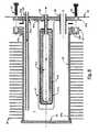
- FIG. 6 is an exploded cross sectional view of the vessel unit shown in FIG. 5.[0038]
- FIG. 7 is a cross section of the vessel unit shown in FIGS. 5 and 6;[0039]
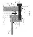
- FIG. 7[0040]ais an enlarged fragmentary sectional view of parts shown in FIGS. 6 and 7 to illustrate a detail of a sealing unit;
- FIG. 8 is a right front perspective view of the hydrogen reformer unit shown in FIG. 4 with the outer enclosure partially removed;[0041]
- FIG. 8[0042]ais a sectional view of a brazed connection of system fluid lines to preheat the feedstock fuel prior to introduction into the pressure vessel;
- FIG. 9 is a left front perspective view of the reformer unit shown in FIGS. 4 and 8, with the outer enclosure partially removed;[0043]
- FIG. 9[0044]ais a left rear perspective view of the reformer unit shown in FIG. 9;
- FIG. 9[0045]bis a cross-sectional view illustrating a parallel heat processing input passageway and an exhaust output passageway with the inter-related system components;
- FIG. 10 is an end view of a heat transfer and recuperative unit shown in FIGS. 8 and 9-[0046]9bfor preheating the air supply to the burner in the instance where the seal between the plates is only formed in one axis;
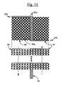
- FIG. 11 is an enlarged view of a heat transfer plate of FIG. 10 with an improved plate separating structure;[0047]
- FIG. 12 is a graphical illustration of the heat input to the catalytic bed and the resulting free hydrogen created; and[0048]
- FIG. 13 is a view of a structure for supplying raffinate to the burner to provide a dispersed flue gas to the finned pressure vessel.[0049]
- FIG. 1 is a simplified illustration of a system for generating purified hydrogen from a hydrogen rich fuel source[0050]1 for consumption by
device 14, which may, for example, be a fuel cell used for supplying electrical power to a load. The illustrated embodiment of FIG. 1 includes aunique hydrogen purifier 18 within a suitable support such asouter housing 36, in combination with the associated components. - The system of FIG. 1 includes a steam reformer having a reformer[0051]
pressure vessel unit 19 which is operable to process fuel/water feedstock from a source1. Although a common pump for the fuel and water is illustrated for the case where the fuel and water are miscible as a pre-mixed feedstock, it is understood that more than one pump may be used for the fuel and water, respectively, along with any needed flow and pressure monitoring means, with the fuel and water streams meeting together prior to arriving at the catalyst filled chamber7. Thepressure vessel unit 19 contains an inner hydrogenpurifier core unit 18. Thepressure vessel unit 19 is larger than theunit 18 and forms the catalyst-filled chamber7. - The fuel from source[0052]1 is shown as a mixture of fuel and water and constitutes a feedstock which is pulled through
line 17 to filter2, and pumped by apump 3 via aline 4 to thecounterflow heat exchanger 9. After receiving heat atheat exchanger 9 the feedstock then receives more heat inheat exchanger 5, finally arriving atpressure vessel 19 by means ofline 6 into pressurevessel inlet connection 60. The feedstock thus is fed into catalyst filled chamber7, which is heated, as hereinafter described, and the fuel/water feedstock reacts to produce free hydrogen.Unit 18 is an elongate member which contains a special hydrogen selective permeable membrane, as hereinafter described, which passes the hydrogen contained in the reformed gases into the interior ofunit 18, wherein the purified hydrogen is subsequently transferred toline 11 by means ofhydrogen outlet 62. While generally illustrated as a tubular member the shape ofunit 18 is not constricted to any particular form, and can assume any form suitable for the application. Hydrogen purified byunit 18 and passing throughline 11 transmits heat to the feedstock inheat exchanger 9 prior to passing through hydrogenoutput pressure regulator 12. Once the hydrogen pressure has been regulated byregulator 12 the hydrogen may then pass throughsolenoid valve 13 to consumingdevice 14. Since consumingdevice 14 may consist of a fuel cell with a required periodic bleed, a return line from consumingdevice 14 is included, with passage throughbleed solenoid valve 15 andcheck valve 16, where the bleed hydrogen is injected intoline 83. - The volume and activity of catalyst[0053]7 and the heating thereof is such that the processed fuel is nearly completely steam-reformed by the time it is withdrawn through
line 8. - The remaining fuel and reaction by-products, including unliberated hydrogen, hereinafter referred to as raffinate, is withdrawn from catalyst-filled chamber[0054]7 by a
line 8. The raffinate then transmits heat to the incoming feedstock inheat exchanger 9, after which it passes through feedstock backpressure regulator 10. The raffinate depressurizes upon passing throughregulator 10 and travels thoughline 83 toburner distributor 21. - A[0055]
catalytic burner 75 is mounted withinouter housing 36 to receive raffinate fromdistributor 21 mixed with burner air. The raffinate is discharged into the air flow via pores or holes indistributor 21, such as more clearly shown in FIG. 13 for a dual-distributor mechanism. The air and raffinate are mixed at the input toburner 75 which creates a hotflue gas stream 75awhich passes into the adjacent chamber and functions as described above to heat the catalyst filled chamber7. - The system shown in FIG. 1, provides particular features for improving the efficiency and functioning of the reforming process for the generation and purification of hydrogen. In particular, the system provides various heat recovery from the heated fluids in the lines at[0056]
heat exchanger 9 and theheated flue gases 78awhich flow downstream ofheat exchanger 5. - As shown in FIG. 1, the portions of[0057]
lines heat exchange unit 9 which transfers heat from the reformed gases back to the incoming feedstock in counterflow fashion. This improves efficiency and also serves to cool the gas prior to arrival athydrogen output regulator 12 andfeedstock pressure regulator 10, protecting the devices from thermal damage. In addition, as also shown in FIG. 1, theline 4 is shown with a coiledheat exchanger section 5 which is in contact with theburner flue gas 79.Heat exchanger 5 is configured to raise the feedstock to the desired operating temperature for the catalyst in catalyst-filled chamber7. Depending on the capacity of the reformer,heat exchanger 5 may include several turns of finned tubing to facilitate heat transfer fromflue gas 79, or it may consist of an unfinned tube with one or more parallel turns. - Additionally, a[0058]
heat transfer assembly 30 is located spanning theexhaust chamber 91 and the burnerair inlet chamber 90 downstream offan 20 andfan filter 20a. Abackup fan 20b, as illustrated in FIG. 2a, may also be used in series with themain fan 20. Thehot flue gas 78aenteringassembly 30 raises the temperature of theassembly 30 on the flue gas side which transmits the heat into the cool portion of theassembly 30 on the air inlet in a counterflow fashion. More specifically, theassembly 30 is specially constructed to prevent the transfer of fluids in the respective chambers into the other chamber, as more fully described in a preferred construction of the system of FIG. 1, as shown in FIGS.2-12, by the use of thermally insulating sealinggasket 97. Insulatinggaskets 97 furthermore allow the perforated or expandedmetal plates 96 ofassembly 30 to operate at different temperatures such that counterflow exchange may be improved. - While the arrangement of heat exchangers regulators, valves, and the like illustrated in FIG. 1 are specifically shown in a preferred orientation, various arrangements of parts may be employed to achieve similar results within the framework of the invention, and may be arranged as needed by those skilled in the art.[0059]
- Referring to FIGS.[0060]2-4, a compact
hydrogen source unit 33 includes an outer enclosure wall34 (partially shown in FIGS. 2a-4) within which anair supply section 35 is formed across the front wall, and connected to a hydrogen generating unit enclosed inenclosure 36. Acontrol section 37 is located to the one side of theair supply section 35 and the hydrogen generator unit inenclosure 36.Section 37 contains various parts previously described in FIG. 1 such as the pressure regulation and solenoid valves. - The[0061]
air supply section 35 includes a housing with anair filter 20awithin which anair supply fan 20 is located with abackup fan 20bdownstream offan 20. As illustrated in FIG. 2athebackup fan 20bis an axial type, and themain fan 20 is of a blower type.Fan 20 pulls air throughfilter 20aand blows it into a housing surroundingbackup fan 20b. Anair passageway tube 38 connects the output end ofbackup fan 20bto the hydrogen generator unit inenclosure 36. The outer face of thehousing 35ais covered byfilter 20aand an outerapertured face cover 38b. - The hydrogen generator unit in[0062]
enclosure 36 is mounted behind theair supply section 35 and is surrounded byperimeter insulation 39 resting on a rigid thermally insulatingbase support platform 39a. The insulation surrounding the high temperature parts contained inenclosure 36 permits the efficient operation of the reformer. Specifically this is done by placing the metallic fastening means toenclosure 36 at the lowest temperature portion ofenclosure 36. This includes theair passageway tube 38, and the top ofunit 33 in FIG. 2, to whichenclosure 36 is fastened. This permits structural attachment ofenclosure 36 to the rest ofdevice 33 while minimizing thermal losses. The input of the air to the generating unit inenclosure 36 is via theair passageway tube 38. It should be noted that theperimeter wall insulation 39 is only partially shown for clarity of illustrations and understanding of the processing of the air and heating fuel system of the preferred system. - Referring to FIGS.[0063]4-8, the
pressure vessel unit 19 of FIG. 1 is shown in a preferred finned construction and identified hereinafter aspressure vessel 40. Thepressure vessel 40 includes an outer shell orcontainer 42 within which an innerpurifier core unit 41 which is centrally located and secured. In the preferred embodiment, a separate cup-shape guard member 51 is secured between the outer shell orcontainer 42 and thepurifier core unit 41. Theguard member 51 is spaced from thecontainer 42 and forms a catalyst chamber7 and is also spaced from thecore unit 41 to prevent abutting engagement of agranular catalyst 50 in chamber7 with thecore unit 41. - In particular, the[0064]
container 42 includes an outertubular wall 45, open at both ends prior to assembly. The outer end is closed by aflat end wall 46 welded withweld 47a(47adenoting all welds in FIGS. 6 and 7) to thetube 45 and spaced from the inner ends of the cup-shapedguard member 51 andpurifier core unit 41. The opposite or inner end of thetube 45 is closed by aheader unit 46aincluding aflange member 47 secured to the open end of thetube 45, as by aweldment 47a.Header unit 46ais bolted withbolts 53 in a sealed connection usingcopper seal ring 52ato theflange member 47. Theguard member 51 and thepurifier core unit 41 are secured to theheader 46ato form a removable unit relative to theflange 47 and theouter shell 45 orcontainer 42.Cover 64 is also attached to theflange 46aviabolts 53. - The cup-shaped[0065]
guard member 51 is formed of suitable perforated metal or other suitable material to confine thecatalyst 50 and to permit free passage of the hydrogen as well as other gaseous material. The open end of theguard member 51 is secured to theheader 46aby welding or other connecting means. - The[0066]
purifier core unit 41 is formed of a porousceramic body 41awith an outer hydrogenpermeable metal coating 41b, with presently known materials such as palladium or a palladium copper alloy coating, forming a hydrogen selective membrane, and thus a hydrogenpurifier core unit 41. The reformed gases pass freely through theguard 51 into thecore unit 41. The hydrogen gas only passes into theinner collection chamber 41cof thecore unit 41 as a result of traversing the outer hydrogenselective membrane 41b. Theguard 51 may take the form of a porous wall, an apertured wall or even a tubular member directing the free hydrogen toward the end thereof, with the hydrogen discharging therefrom, into the membrane unit. Where the catalyst is in the form of one or more monolithic catalyst elements or units mounted in spaced relation to the selective membrane unit or units, theguard 51 may not be necessary. - Referring to FIG. 7[0067]a, the
flange 47 is recessed and telescoped over the outer end of thetube 45 and is welded to the exterior of thetube 45 as at47a. Theheader 46ais bolted to theflange 47 with a high pressure sealedgasket 52atherebetween. The illustrated sealed joint (FIG. 7a) includes acopper seal ring 52alocated between theflange 47 andheader 46a. Asharp sealing edge 52cprojects outwardly from47 and46ainto embedded engagement with thecopper ring 52aupon tightening of thesecurement bolts 53. The seal establishes a high pressure closure to confine reformed gases withinvessel 40. Other suitable seals may be used in the preferred system, and in other systems may be constructed without a removable cover structure. For example,end piece 46amay be welded or brazed to the end oftube 45 for a permanent closure ofpressure vessel 40. - The input/output lines are sealed within[0068]
header 46aand are coupled to the several passages within thecore unit 41 and catalyst chamber7 of the illustrated embodiment, as follows. - A[0069]
feedstock fuel line 60 is secured in sealed relation to theheader 46a. Thefuel line 60 extends inwardly into the catalyst-filled chamber7, and through thecatalyst 50 to the inner end portion of the chamber. The inner end ofline 60 terminates, close to theend wall 46 to feed the hydrogen rich feedstock fuel into the closed end of the catalyst filled chamber7, under appropriate pressure, to move the feedstock axially through thecatalyst 50 toward theheader 46a. An alternate arrangement within the scope of this invention (not shown) utilizes afeedstock delivery tube 60 and araffinate exit tube 63 which extends the length of catalyst bed7, where the tubes are closed at the ends and perforated, such that the gas flows between the perforated tubes rather than down the axial length of the catalyst bed. Other arrangements within the pressure vessel apparent to those skilled within the art can be implemented as well. - A[0070]
hydrogen recovery line 62 is secured within theheader 46aand terminates at theinner core chamber 41cofcore unit 41 and serves to recover the free hydrogen which has passed through themembrane 41bofpurifier core unit 41. - A[0071]
raffinate line 63 is secured to theheader 46ain alignment with the lower or bottom side of the catalyst chamber7. The pressurized feedstock passes through thecatalyst 50 and exits as raffinate through theraffinate line 63 under pressure. The raffinate generally contains a significant level of hydrogen and functions as a fuel for the catalytic burner in the air passageway, as hereinafter described. - The raffinate at the outlet of the catalyst, downstream of the[0072]
purifier unit 41, can provide a fuel to a catalytic or other burner unit. Unreformed fuel, unrecovered hydrogen, and side-reaction products such as carbon monoxide or methane can serve to function as a fuel in a catalytic or other burners. The particulars of gases contained in the raffinate depend upon the fuel type, steam-to-carbon ratio, pressure, catalyst type, flow rate, and temperature, and may also vary depending on the time on stream of the catalyst. The reformed feedstock with hydrogen removed bypurifier 41 is generically identified herein as raffinate, which will cover all reformed feedstock exiting a catalyst unit and a hydrogen purification unit and coupled to the system burner, as disclosed herein, as well as such fuel when combined with or replaced by a separate fuel source. - The[0073]
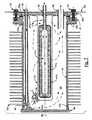
container 42 and particularly thetubular wall 45 has spaced and heatconductive fins 59 intimately secured, as by brazing or other high heat transmitting connection, to thecontainer wall 45. Thefins 59 are shown as rectangular members which are shaped and formed to fit within the corresponding opening in the enclosure for optimal heating of the catalyst and generation of purified hydrogen, as hereinafter described. Thefins 59 are spaced, with size and positioning selected to provide rapid heating of the vessel, while yielding a minimal pressure drop for the laterally passing flue gas flow. Thefins 59 are preferably formed of a suitable material such as copper for rapid heat transfer to the vessel, and particularly tocatalyst 50. - The pressure vessel[0074]40 (FIG. 4) is removably secured within an
opening 65 in theenclosure 36 by aplate 64 secured to theheader 46aand to the enclosure frame structure byattachment screws 65a. Thefinned vessel 40 is enclosed within an internal wall structure to define an air/fuel inlet passageway and an outer exhaust passageway, as hereinafter described. - The finned[0075]
pressure vessel 40 and particularlypurifier core unit 41 thereof may require replacement in the event that a breach or other degradation ofmembrane 41boccurs, or if the catalyst activity declines significantly due to coking, poisoning, aging, or other reasons. The other components are expected to have a long life. - As shown, the[0076]
finned pressure vessel 40 is removable as a unit. The illustratedheader 46amay be released fromflange 47 and replaced by a new header with a new core unit and guard unit within thefinned container 42. The catalyst may also be replaced during this operation, which is particularly straightforward if the catalyst is formed as a monolithic annular piece rather than the granular material illustrated as50. The illustrated unit thus provides for a lowcost replacement purifier 41 andpressure vessel 40 for simple serviceability and long life operation of the reformer. - The[0077]
feedstock feed line 60, the hydrogen (H2)recovery line 62 and theraffinate line 63 are secured toheader 46ain spaced relation for inputting the feedstock and withdrawing the purified hydrogen and the raffinate, relative tocontainer 42, as shown in FIGS. 8 and 9. Each line is similarly constructed with a likeline coupling unit 67 which may be released and later re-sealed when servicing the unit. - The[0078]
raffinate line 62 additionally may have a largerreleasable coupling 68 betweenheader 46aand thecoupling 67 to open theline 63. This provides convenient means for replacing thegranular catalyst 50, as may be periodically required. As previously mentioned, when the catalyst consists of one or more monolithic members,header 46amust be removed to replace the monolithic catalyst, in whichcase coupling 68 becomes unnecessary. - The[0079]
pressure vessel 40 is removably mounted within theenclosure 36, as shown in FIGS. 4, 8 and9-9bbyfastening screws 65a. Thehousing enclosure 36 further contains a variety of interior walls and flow directing means to channel the heating gases through the enclosure. As best shown in FIG. 9b, an uppervertical divider wall 69 divides theair inlet plenum 90 from theexhaust gas plenum 91, extending between and abuttingrecuperator assembly 30 and the top ofenclosure 36, as well as the sides ofenclosure 36 to form an effective barrier betweenplenums assembly 30, rigid thermally insulatingvertical divider wall 70 further separates the gas flow.Vertical wall 70 abuts and seals to rigid thermally insulatinghorizontal wall 71.Horizontal wall 71 contains anopening 74 permitting the mixed air and raffinate to flow intocatalytic burner 75; otherwisehorizontal wall 71 abuts and seals against theouter enclosure 36 andvertical wall 70 to prevent the flow of gases elsewhere.Horizontal wall 71, in combination with the bottom and sides ofenclosure 36 and the spacedfins 59 ofvessel 40, forms apassageway 74bforflue gas 75aforheating fins 59 and the interior ofvessel 40. Downstream ofvessel 40, vertical fluegas divider wall 73 formed of rigid thermally insulating material, abutting and sealing againstwall 71 and sides ofenclosure 36, directs the flue gas throughpassageway 76 in itsopening 78.Wall 73 and theenclosure 36 further define a vertical passage way forflue gas 79, containingheat exchanger 5. - [0080]
Heat exchanger 5, illustrated as several coils of finned tubing (FIGS. 9aand9b) is connected within thefeedstock line 60 which is connected to theincoming feedstock line 4 to the catalyst bed, as hereinafter described. Thefinned tubing 5 is located in that portion of exhaustingflue gas 79 passing therethrough and is effective for preheating the feedstock inheat exchanger 5 prior to its sequential introduction intoline 6,connector 67, andline 60 arriving at thecatalyst 50. - Referring to FIGS. 1, 4,[0081]8 and9, the raffinate supply connection from the
reformer vessel 40 to theburner 75 is illustrated, with the lines coupling for preheating the feedstock.Raffinate line 63exits vessel 40 throughcoupling Raffinate line 8 passes throughheat exchanger 9, and then intocontrol section 37 containing feedstock/raffinate backpressure regulator 10. Theback pressure regulator 10 depressurizes the raffinate where it then is allowed to combine with fuel cell bleed hydrogen before arriving atburner feed line 83.Burner feed line 83 then passes intoenclosure 36 to the burner distributor. An illustrative burner distributor is shown in FIG. 13 showing a tee fitting86 and twoperforated distributors burner 75. - Each tube[0082]85-85ais hollow and sealed at the outer most ends. Each tube8585ais preferably a porous or perforated material, such as a ceramic material, a sintered metal, or perforated tubing or other like functioning material. At the start of the system operation, the
inlet air 74ainpassageway 74 is relatively cold air and the raffinate cannot be generated until the catalytic bed is at a temperature sufficient to process feedstock. To initiate the bed activation, and to preheat theburner 75 to a temperature sufficient to allow for catalytic combustion of raffinate, an auxiliary heating source is normally required during start-up. Anelectrical heater 88 is shown mounted (FIGS.9-9a) above theburner 75. Theheater 88 is turned on automatically during the start up of the system to heat the inlet air supply to the temperature necessary for raising the catalytic burner temperature to the “light-off” temperature, and the catalyst bed to a temperature sufficient to reform the fuel. Once this temperature is achieved thepump 3 may start pumping feedstock into the device, resulting in generation of the hydrogen freeing reaction in thecatalyst 50 and the subsequent raffinate fuel for firing of theburner 75. For alcohol based feedstock, the necessary catalyst bed temperature is on the order of 250-500° C., depending on the fuel and catalyst choice, and the catalytic burner light-off temperature for hydrogen in the raffinate is above approximately 100° C. After the “light-off” state is established at the burner, theheater 88 for heating of the inlet air supply may be terminated because the raffinate entering theburner 75 is then adequate to maintain the proper heating of the catalyst. The preheating of the feedstock as described in the preferred construction, further maintains the proper reactance in the catalyst without an auxiliary heat source after light-off. - The raffinate (FIGS. 9 and 9[0083]b) is mixed with the air flow in the
air inlet passageway 74 and the mixture passes into and through theburner 75 which burns to form high temperature fluid orflue gas 75a. Theflue gas 75aflows directly into theinlet passageway 74b, to and overpressure vessel 40 as shown in FIGS. 4, 8 and9b. Theheated flue gas 75apasses through the fins and over thecontainer 42 ofpressure vessel 40 as the only exit from the supply orinlet passageway 74b. Thefins 59 are suitably spaced transfer the heat into thepressure vessel 40 to heat thecatalyst 50 and thereby generate the hydrogen for capture within thecore unit 41. Although the feedstock is preheated, as previously described, the reforming reactions requires the additional heat input from the burner to compensate for the endothermic reaction to produce hydrogen. - The heating of the[0084]
catalyst 50 may include special distribution on the axis of the bed or catalyst unit. An optimalheat distribution curve 100 and a resultingreaction curve 101 are shown in FIG. 12. Theheat distribution curve 100 is high over approximately the first half of thecatalyst 50 and then gradually decreases to a low level adjacent the exit or discharge end of the catalyst, since the bulk of the endothermic reaction occurs at the beginning of the catalyst bed. The resultingreaction curve 101 for generating the free hydrogen includes a rapid increase in the hydrogen over the high heat input portion and then levels off to a slight release curve to the exit or discharge end of thecatalyst 50. - Since the heating requirements are higher at the beginning of the catalyst bed, a higher heat flux is desired in this region compared to the exit of the catalyst bed. This can be accomplished by decreasing the spacing of the fins nearer the feedstock inlet, or by increasing the temperature of[0085]
flue gas 75aat the nearer the feedstock inlet, or a combination of both. - FIG. 13 illustrates a special construction of the raffinate input to the[0086]
burner 75 for the optional heating distribution of the vessel. The raffinate distribution holes in85 and85aare varied to supply a richer raffinate/air mix nearer the feedstock inlet end of the catalyst bed7, while the exit ends of85 and85ahave fewer holes, providing a leaner raffinate/air mix. The richest and therefore hottest flue gas is therefore applied at the entrance end of the catalyst bed7 and the leanest and therefore coolest flue gas at the exit end of the bed7, generally in accordance with the illustration. - In an alternate configuration the catalytic burner may reside on the surface of the vessel or on the fins secured to the vessel. Methods for forming catalytic surfaces via methods of coating are known to those skilled in the art and are not discussed in further detail. If the catalytic burner is coated on the fins, the fins are preferably closely spaced throughout the length of the catalyst unit. This is necessary to insure that un-burned raffinate does not slip past the fins and flow into the[0087]
exhaust passageway 76 with the exitingflue gas 79. In this case it is also preferable to use the graduated burner diffuser illustrated in FIG. 13. - A preferred feedstock heat exchanger illustrated as[0088]
finned unit 5 is shown in FIGS. 4, 8 and8a. Thelines vessel 40 via couplings include lengths of bare metal tubes which are assembled with a metal tube ofcold feedstock line 4 in positive abutting engagement. The bare metal tubes are held in abutting and heat transfer engagement by a suitable coupling, preferably by a heat transfer bond; for example, brazing or welding the three tubes to each other throughout a substantial length as at84c, or otherwise similar by connecting the tubes with other heat-transmitting and bonding materials. The bondedtubes cloth 84bover the bonded tubes. The bonded lines are assembled in a counterflow assembly with the coldest end of thefeedstock line 4 abutting the coldest ends oflines heat exchanger 5 also serves to cool the hydrogen and raffinate prior to arriving atregulators - The bonded[0089]
lines vessel 40 and the inner core unit so that the heat exchanger unit is sized or scaled to the system size with thevessel 40 and the inlet and exhaust as well as for system scaling as hereinafter discussed. - This also provides a relatively simple but highly effective system for heating of the feedstock. Other systems of coupling the lines to each other may be used. As a result of the recovery of heat and preheating of the feedstock, the required heating of the catalyst bed for effective generation of purified hydrogen is reduced, and the counterflow arrangement of the heat exchanger increases efficiency.[0090]
- As shown in FIGS.[0091]8-9b, the
air inlet plenum 90 is formed to one side ofwall 69 and extended over one half of the top ofenclosure 36. Similarly, the other half of the top ofenclosure 36 containsexhaust chamber 91 to the other side of the dividingwall 69. Ambient air fromfan 20 arrives inplenum 90 throughair inlet 38, and exhaust leavingplenum 91 exits viaexhaust aperture 92. - In accordance with the preferred construction and as shown in FIGS. 1 and 89[0092]b, a
heat recovery structure 30 couples in counterflow fashion the heat in theexhaust flue gas 78ato the air arriving throughair inlet 38asfollows. - The[0093]
air inlet chamber 90 of FIGS. 1, 8 and9 is connected to the air supply tube orpassageway 38 shown in FIGS. 2a-3. Theexhaust chamber 91 includes theexhaust opening 92 in the rear structural wall, as shown in FIGS. 3, 8 and9b. - A[0094]
multiple plate assembly 30 is secured belowwall 69, spanning the inlet air and exhaust flue gas streams. - FIGS. 10 and 11 are enlarged pictorial views of the heat[0095]
transfer plate assembly 30 withenlarged plates 96 for clearly illustrating one preferred construction of the heat recuperating system for heating the incoming air supply. Themultiple plate assembly 30 includes a plurality ofheat transfers plates 96 separated by heat insulating and fluid closingwall gasket members 97 which maintain separation of the incoming air with the exiting flue gas, while allowing theplates 96 to pass through and span the incoming air and exiting flue gas regions. Theplates 96 may be formed as like plates of a suitable metal such as copper, aluminum or other materials which are a good heat transmitting material. The illustrated diamond shapedopenings 96a, or any other shaped openings may be formed in the metal plates. The openings need not have the same shape or size, nor are the openings in the adjacent plates necessarily aligned with each other. The size and frequency of the openings in the plates is scaled sufficient to allow for easy passage of the air and flue gas with a minimal pressure drop in the respective gas streams. The openings also allow for a high surface area for transferring heat into and out of the plates. - The[0096]
plates 96 andwall members 97 are preferably thin elements. Typically, theplates 96 have a thickness of 0.005-0.100 inches, and more preferably 0.020-0.05 inches. The thickness of the plates is scaled sufficient to yield a low temperature drop while transmitting heat from the flue gas to the incoming air, and depends somewhat on the metals used and the desired heat flux needed through the plates. The separatingwall members 97 may have a similar thickness or may be thicker than the plates if desired. The insulating properties of themembers 97 are chosen to sufficiently thermally isolateadjacent plates 96; this allows for plates to operate at different temperatures thus permitting counterflow heat exchange between the two gas streams. The lowest plate, in contact with thehottest flue gas 78a, is therefore at the highest temperature, while the highest plate, in contact with the incoming ambient air, is at the lowest temperature. - As illustrated in FIG. 10, the separating[0097]
wall member 97 does not encourage parallel alignment ofplates 96 in recuperatingassembly 30. For this reason, member97(a) is augmented with extendinglegs 97bas shown in FIG. 11. Stacking of a plurality ofmembers assembly 30 thus forces parallel alignment ofplates 96. - Although not illustrated, other embodiments of counterflow[0098]
heat exchange element 30 are possible. For example, in an annulararrangement sealing member 97 becomes donut-shaped, and extendinglegs 97bare no longer required to yield a parallel orientation ofplates 96, where the plates extend between an inner and outer annulus for heat transfer. In yet another configuration, two separate perforated plates may be folded into a serpentine pattern, yielding parallel plates. These two pieces may be brazed together with a thin piece of metal which serves asdivider 97. One serpentine assembly of parallel plates would extend into the air plenum, while the other would extend into the flue gas plenum, and the heat transfer between plenums would occur at the brazed joint over thesingle metal divider 97. Other additional variations may be obvious to those skilled in the art. - In summary, the illustrated embodiment discloses a preferred construction for preheating the supply input air which is supplied to[0099]
burner 75. A practical assembly only needs to include plates or other elements which provide effective heat transfer of the heat in the exhaust gas to the inlet air via mounting of the elements in sealed relation within a separating wall; within the broadest aspect of the present invention. - The construction for the recovery of the heat in the exhaust gas should include the relatively large cross-sectional flow areas of the chambers and the associated air and exhaust passageways as well as relatively large openings within the heat transfer plates or other heat transfer elements forming like large openings such that the structure creates a low pressure drop, and a resulting low power consumption to supply air through[0100]
fan 20. - Like consideration is given to the passageway associated with the heating of the[0101]
pressure vessel 40. Thus, thecatalytic burner 75 preferably has a relatively large cross-section and is formed with a substantial plurality of like parallel passages in the direction of the air/fuel flow therethrough. - For example, a two-inch deep burner having passages on the order of 200 cells per square inch and of an extruded ceramic with a precious metal coating is one example of a higher satisfactory burner, in accordance with known construction. The recuperator for heating the input air may likewise be formed from aluminum in an expanded and rolled pattern with an open area approaching 40%.[0102]
- The[0103]
pressure vessel 40 is similarly and preferably constructed with a relatively large finned construction and with proper spacing of the fins to establish a low system pressure drop in the gases passing over the vessel, as isheat exchanger 5. - The other heat recovery systems such as the preheat of the feedstock fuel and the recovery of the heat from the purified hydrogen and the reformed gases within the system also provide significant results in producing an efficient and improved reforming apparatus.[0104]
- The combined structure with the special air and fuel supplies including the heat exchanges at the air inlet and exhaust passageways, the feedstock preheat coil, the coupled flow lines, the catalytic burner and the finned pressure vessel may yield a significantly low burner gas pressure drop. As a result, the electrical power requirement for moving of the air and flue gases into and through the unit is low. This, in combination with low thermal losses, yields a corresponding increase in reformer efficiency.[0105]
- The unique characteristic of the illustrated design also allows for cost effective scalable construction of the systems with different maximum output levels. The several components and parts of the illustrated embodiment with the linear axis permits construction of the vessel of different capacity by designing the linear length of the components to be directly related to the desired capacity. Thus, each of the interacting components including the burner area, heat exchange area, the catalyst volume, purifier membrane area, the exhaust heat transfer system, the counter flow heating unit coupling the feedstock line to the raffinate line and/or the hydrogen line are directly related to the length on the linear axis of the elements and components and therefore the final structure, as disclosed herein.[0106]
- For example, if the length of the pressure vessel is doubled, the lengths of the air and exhaust chambers, the inlet air supply and feedstock heat transfer units, and the burner and related passageway will double, producing a doubled output capacity.[0107]
- The design and structure of the device is particularly unique in allowing for the ease in scalability, but also provides a cost effective service construction. In the purifier, the membrane and catalyst component may require periodic replacement and is readily replaced in the preferred embodiment. Service in the field may thus consist of simply and easily replacing the entire finned pressure vessel containing the purifier unit and catalyst, or replacing the guard and core unit as attached to the header while reusing the finned vessel and flange unit.[0108]
- The illustrated embodiment may process any of a variety of feedstocks. Although illustrated in the preferred embodiment using a miscible water/fuel feedstock, separate fuel and water supply means may be employed, for a variety of fuels, and which may include various other steps such as fuel desulphurization, water conditioning, and the like, in accordance with typical feed conditioning steps as disclosed in the known art. Likewise, the size and placement of the various components may be varied in keeping with the present disclosure. For example, improvements in membrane technology will allow for a much smaller membrane collector area, and similar improvements in catalyst may allow for a smaller catalyst volume.[0109]
- The specific monitoring, operation, and control of the reformer, with the typical user interface requirements such as[0110]
LCD display 22 and operator controls23 (see FIG. 2), involve devices, hardware, operating states, and algorithms previously disclosed and known to those skilled in this art. A typical example can be found in “PC-25 C On-Site Fuel Cell Power Plant Service Manual Volume 1”, ONSI Corporation (April 1996), and the like. - In summary, the present invention provides an improved and unique reformer structure for generating of purified hydrogen from the various fuels containing hydrogen. The illustrated preferred embodiment of the invention also provides a reforming system which is operable with a low pressure drop in the air supply system, with a resulting cost effective system.[0111]
Claims (55)
Priority Applications (9)
| Application Number | Priority Date | Filing Date | Title |
|---|---|---|---|
| US10/263,949US7341609B2 (en) | 2002-10-03 | 2002-10-03 | Reforming and hydrogen purification system |
| AU2003282674AAU2003282674A1 (en) | 2002-10-03 | 2003-10-03 | Reforming and hydrogen purification system |
| PCT/US2003/031487WO2004031073A2 (en) | 2002-10-03 | 2003-10-03 | Reforming and hydrogen purification system |
| BR0314535-2ABR0314535A (en) | 2002-10-03 | 2003-10-03 | Reform and hydrogen purification system |
| CA2501137ACA2501137C (en) | 2002-10-03 | 2003-10-03 | Reforming and hydrogen purification system |
| CNB2003801047927ACN100411972C (en) | 2002-10-03 | 2003-10-03 | Reforming and Hydrogen Purification Systems |
| JP2004541679AJP4598529B2 (en) | 2002-10-03 | 2003-10-03 | Reforming and hydrogen purification equipment |
| EP03774560AEP1546031A2 (en) | 2002-10-03 | 2003-10-03 | Reforming and hydrogen purification system |
| US12/034,325US20080134577A1 (en) | 2002-10-03 | 2008-02-20 | Reforming and Hydrogen Purification System |
Applications Claiming Priority (1)
| Application Number | Priority Date | Filing Date | Title |
|---|---|---|---|
| US10/263,949US7341609B2 (en) | 2002-10-03 | 2002-10-03 | Reforming and hydrogen purification system |
Related Child Applications (1)
| Application Number | Title | Priority Date | Filing Date |
|---|---|---|---|
| US12/034,325DivisionUS20080134577A1 (en) | 2002-10-03 | 2008-02-20 | Reforming and Hydrogen Purification System |
Publications (2)
| Publication Number | Publication Date |
|---|---|
| US20040065013A1true US20040065013A1 (en) | 2004-04-08 |
| US7341609B2 US7341609B2 (en) | 2008-03-11 |
Family
ID=32042113
Family Applications (2)
| Application Number | Title | Priority Date | Filing Date |
|---|---|---|---|
| US10/263,949Expired - LifetimeUS7341609B2 (en) | 2002-10-03 | 2002-10-03 | Reforming and hydrogen purification system |
| US12/034,325AbandonedUS20080134577A1 (en) | 2002-10-03 | 2008-02-20 | Reforming and Hydrogen Purification System |
Family Applications After (1)
| Application Number | Title | Priority Date | Filing Date |
|---|---|---|---|
| US12/034,325AbandonedUS20080134577A1 (en) | 2002-10-03 | 2008-02-20 | Reforming and Hydrogen Purification System |
Country Status (8)
| Country | Link |
|---|---|
| US (2) | US7341609B2 (en) |
| EP (1) | EP1546031A2 (en) |
| JP (1) | JP4598529B2 (en) |
| CN (1) | CN100411972C (en) |
| AU (1) | AU2003282674A1 (en) |
| BR (1) | BR0314535A (en) |
| CA (1) | CA2501137C (en) |
| WO (1) | WO2004031073A2 (en) |
Cited By (30)
| Publication number | Priority date | Publication date | Assignee | Title |
|---|---|---|---|---|
| US20040163313A1 (en)* | 2003-02-20 | 2004-08-26 | Buxbaum Robert E. | Hydrogen generation apparatus |
| US20050005521A1 (en)* | 2003-06-27 | 2005-01-13 | Ultracell Corporation | Fuel processor dewar and methods |
| US20060104879A1 (en)* | 2004-11-12 | 2006-05-18 | Applied Materials, Inc. | Reactor design to reduce particle deposition during process abatement |
| US20060137245A1 (en)* | 2004-12-17 | 2006-06-29 | Texaco Inc. | Apparatus and method for producing hydrogen |
| US20060156627A1 (en)* | 2003-06-27 | 2006-07-20 | Ultracell Corporation | Fuel processor for use with portable fuel cells |
| US20070086931A1 (en)* | 2005-06-13 | 2007-04-19 | Applied Materials, Inc. | Methods and apparatus for process abatement |
| US20070169889A1 (en)* | 2005-10-31 | 2007-07-26 | Clark Daniel O | Methods and apparatus for selectively coupling process tools to abatement reactors |
| US20070240408A1 (en)* | 2006-04-14 | 2007-10-18 | Ewa Environmental, Inc. | Particle burner including a catalyst booster for exhaust systems |
| US20070251222A1 (en)* | 2006-04-26 | 2007-11-01 | Ewa Environmental, Inc. | Reverse flow heat exchanger for exhaust systems |
| US20080003151A1 (en)* | 2006-02-11 | 2008-01-03 | Applied Materials, Inc. | Methods and apparatus for pfc abatement using a cdo chamber |
| US20080166277A1 (en)* | 2007-01-09 | 2008-07-10 | In-Hyuk Son | Plate type preferential oxidation reactor |
| US20080244973A1 (en)* | 2004-01-30 | 2008-10-09 | Idemitsu Kosan Co., Ltd. | Reformer |
| US20080271448A1 (en)* | 2007-05-03 | 2008-11-06 | Ewa Environmental, Inc. | Particle burner disposed between an engine and a turbo charger |
| US20080314035A1 (en)* | 2006-04-14 | 2008-12-25 | Lincoln Evan-Beauchamp | Temperature Ladder and Applications Thereof |
| US20090010816A1 (en)* | 2003-12-19 | 2009-01-08 | Applied Materials, Inc. | Apparatus and method for controlled combustion of gaseous pollutants |
| US20090155642A1 (en)* | 2007-12-17 | 2009-06-18 | Idatech, Llc | Systems and methods for reliable feedstock delivery at variable delivery rates |
| US7566423B2 (en) | 2006-04-26 | 2009-07-28 | Purify Solutions, Inc. | Air purification system employing particle burning |
| US20090199475A1 (en)* | 2008-02-12 | 2009-08-13 | Genesis Fueltech, Inc. | Reformer and Method of Startup |
| US20110044868A1 (en)* | 2008-01-25 | 2011-02-24 | Sk Energy Co., Ltd. | Steam Methane Reformer and Hydrogen Station Having it Using High Performing Metal Fiber Burner |
| US20110067572A1 (en)* | 2009-09-18 | 2011-03-24 | General Electric Company | Sorbent Activation Plate |
| US8821832B2 (en) | 2003-06-27 | 2014-09-02 | UltraCell, L.L.C. | Fuel processor for use with portable fuel cells |
| US8961627B2 (en) | 2011-07-07 | 2015-02-24 | David J Edlund | Hydrogen generation assemblies and hydrogen purification devices |
| US9187324B2 (en) | 2012-08-30 | 2015-11-17 | Element 1 Corp. | Hydrogen generation assemblies and hydrogen purification devices |
| NO20161175A1 (en)* | 2016-07-14 | 2018-01-15 | Zeg Power As | Method and power plant comprising a Solid Oxide Fuel Cell (SOFC) for production of electrical energy and H2 gas |
| US9914641B2 (en) | 2012-08-30 | 2018-03-13 | Element 1 Corp. | Hydrogen generation assemblies |
| CN110137546A (en)* | 2018-02-09 | 2019-08-16 | 丰田自动车株式会社 | Fuel cell system |
| US10717040B2 (en) | 2012-08-30 | 2020-07-21 | Element 1 Corp. | Hydrogen purification devices |
| CN111825057A (en)* | 2020-08-07 | 2020-10-27 | 广东能创科技有限公司 | Temperature control system and temperature control method for palladium tube purifier in methanol water hydrogen generator |
| US11738305B2 (en) | 2012-08-30 | 2023-08-29 | Element 1 Corp | Hydrogen purification devices |
| US12187612B2 (en) | 2021-06-15 | 2025-01-07 | Element 1 Corp | Hydrogen generation assemblies |
Families Citing this family (19)
| Publication number | Priority date | Publication date | Assignee | Title |
|---|---|---|---|---|
| US7297183B2 (en)* | 2004-09-20 | 2007-11-20 | Idatech, Llc | Hydrogen purification devices, components, and fuel processing systems containing the same |
| JP4863194B2 (en)* | 2005-09-29 | 2012-01-25 | 株式会社Eneosセルテック | Fuel reformer for fuel cell |
| FR2918978B1 (en) | 2007-07-20 | 2010-02-12 | Inst Francais Du Petrole | NOVEL HYDROGEN PURIFICATION PROCESS USING A COMBINATION OF MEMBRANE SEPARATION UNITS |
| CN101723325B (en)* | 2008-10-29 | 2011-09-21 | 中国石油化工股份有限公司 | Method for recovering low-concentration hydrogen |
| US8038939B2 (en)* | 2009-06-09 | 2011-10-18 | Atrion Medical Products, Inc. | Method and devices for improved disinfection process |
| US8240370B2 (en)* | 2009-12-18 | 2012-08-14 | Air Products And Chemicals, Inc. | Integrated hydrogen production and hydrocarbon extraction |
| CA2817375C (en)* | 2010-11-08 | 2019-04-30 | Ze Energy Inc. | Gasification furnace, gasification system, reformer and reforming system |
| JP6197301B2 (en)* | 2013-02-14 | 2017-09-20 | 日本特殊陶業株式会社 | Hydrogen production equipment |
| FR3027381A1 (en)* | 2014-10-21 | 2016-04-22 | Air Liquide | REFORMING OVEN COMPRISING FINNED REFORMING TUBES |
| DK178933B1 (en)* | 2016-05-31 | 2017-06-12 | Serenergy As | A fuel cell system with an extruded reformer chamber and a method of operation the fuel cell system |
| KR102397390B1 (en) | 2016-11-09 | 2022-05-16 | 8 리버스 캐피탈, 엘엘씨 | Systems and methods for power generation with integrated hydrogen production |
| WO2019092654A2 (en) | 2017-11-09 | 2019-05-16 | 8 Rivers Capital, Llc | Systems and methods for production and separation of hydrogen and carbon dioxide |
| CN109179322B (en)* | 2018-11-09 | 2023-11-10 | 沈阳航空航天大学 | An online methanol reformer that uses engine exhaust heat to produce hydrogen-rich gas |
| AU2020292848A1 (en) | 2019-06-13 | 2022-02-03 | 8 Rivers Capital, Llc | Power production with cogeneration of further products |
| CN111313059A (en)* | 2020-03-26 | 2020-06-19 | 广东能创科技有限公司 | A methanol-water-hydrogen fuel cell generator |
| CA3238616A1 (en) | 2021-11-18 | 2023-05-25 | Rodney John Allam | Method for hydrogen production |
| CN116265381B (en)* | 2022-12-12 | 2024-08-09 | 四川创达新能科技有限公司 | Coil assembly, mixed gas preheating device and steam reforming hydrogen production furnace |
| WO2025078974A2 (en) | 2023-10-09 | 2025-04-17 | 8 Rivers Capital, Llc | Systems and methods for producing hydrogen with integrated capture of carbon dioxide |
| CN118083912B (en)* | 2023-12-28 | 2025-03-25 | 江苏常氢科技工程研究院有限公司 | A hydrogen purification device for desulfurization using a metal nano-mesoporous structure catalyst |
Citations (22)
| Publication number | Priority date | Publication date | Assignee | Title |
|---|---|---|---|---|
| US4430304A (en)* | 1981-11-13 | 1984-02-07 | The United States Of America As Represented By The United States Department Of Energy | Slab reformer |
| US4849187A (en)* | 1987-03-31 | 1989-07-18 | Toyo Engineering Corporation | Steam reforming apparatus |
| US4904455A (en)* | 1985-06-27 | 1990-02-27 | Stone & Webster Engineering Corporation | Production of synthesis gas using convective reforming |
| US5198002A (en)* | 1992-03-12 | 1993-03-30 | The United States Of America As Represented By The United States Department Of Energy | Gas stream clean-up filter and method for forming same |
| US5215729A (en)* | 1990-06-22 | 1993-06-01 | Buxbaum Robert E | Composite metal membrane for hydrogen extraction |
| US5226928A (en)* | 1989-12-26 | 1993-07-13 | The Tokyo Electric Power Company, Incorporated | Reforming apparatus for hydrocarbon |
| US5401589A (en)* | 1990-11-23 | 1995-03-28 | Vickers Shipbuilding And Engineering Limited | Application of fuel cells to power generation systems |
| US5484577A (en)* | 1994-05-27 | 1996-01-16 | Ballard Power System Inc. | Catalytic hydrocarbon reformer with enhanced internal heat transfer mechanism |
| US5525322A (en)* | 1994-10-12 | 1996-06-11 | The Regents Of The University Of California | Method for simultaneous recovery of hydrogen from water and from hydrocarbons |
| US5580523A (en)* | 1994-04-01 | 1996-12-03 | Bard; Allen J. | Integrated chemical synthesizers |
| US5589599A (en)* | 1994-06-07 | 1996-12-31 | Mcmullen; Frederick G. | Pyrolytic conversion of organic feedstock and waste |
| US5637259A (en)* | 1995-12-04 | 1997-06-10 | Natural Resources Canada | Process for producing syngas and hydrogen from natural gas using a membrane reactor |
| US5639431A (en)* | 1993-03-16 | 1997-06-17 | Tokyo Gas Co. Ltd. | Hydrogen producing apparatus |
| US5674301A (en)* | 1994-05-23 | 1997-10-07 | Ngk Insulators, Ltd. | Hydrogen preparing apparatus |
| US5679249A (en)* | 1991-12-24 | 1997-10-21 | Pall Corporation | Dynamic filter system |
| US5738708A (en)* | 1995-06-07 | 1998-04-14 | The Regents Of The University Of California Office Of Technology Transfer | Composite metal membrane |
| US5741474A (en)* | 1994-05-23 | 1998-04-21 | Ngk Insulators, Ltd. | Process for production of high-purity hydrogen |
| US5741605A (en)* | 1996-03-08 | 1998-04-21 | Westinghouse Electric Corporation | Solid oxide fuel cell generator with removable modular fuel cell stack configurations |
| US5861137A (en)* | 1996-10-30 | 1999-01-19 | Edlund; David J. | Steam reformer with internal hydrogen purification |
| US5938800A (en)* | 1997-11-13 | 1999-08-17 | Mcdermott Technology, Inc. | Compact multi-fuel steam reformer |
| US6207132B1 (en)* | 1998-12-04 | 2001-03-27 | Chinese Petroleum Corporation | Process for producing high purity hydrogen |
| US6294149B1 (en)* | 1997-12-16 | 2001-09-25 | Xcellsis Gmbh | Process for operating a water vapor reforming system, a reforming system operable thereby and a fuel cell system operating process |
Family Cites Families (51)
| Publication number | Priority date | Publication date | Assignee | Title |
|---|---|---|---|---|
| US2947152A (en)* | 1955-11-06 | 1960-08-02 | Philips Corp | Heat exchanger for separating out constituents from a gas by cooling |
| US3607125A (en)* | 1968-12-30 | 1971-09-21 | Gen Electric | Reformer tube construction |
| CH561889A5 (en)* | 1973-04-13 | 1975-05-15 | Schrade Jean | |
| US5025856A (en)* | 1989-02-27 | 1991-06-25 | Sundstrand Corporation | Crossflow jet impingement heat exchanger |
| JP3035038B2 (en) | 1991-11-25 | 2000-04-17 | 三菱重工業株式会社 | Hydrogen production method |
| US6098620A (en) | 1993-01-29 | 2000-08-08 | Aradigm Corporation | Device for aerosolizing narcotics |
| JP3197095B2 (en)* | 1993-03-16 | 2001-08-13 | 東京瓦斯株式会社 | Hydrogen production equipment |
| JP3213430B2 (en) | 1993-03-31 | 2001-10-02 | 日本碍子株式会社 | Gas separator and method for producing the same |
| JPH07153320A (en) | 1993-11-29 | 1995-06-16 | Furukawa Electric Co Ltd:The | Multilayer insulated wire and transformer using the same |
| DE4341438C2 (en) | 1993-12-04 | 2000-07-13 | Binsmaier Hannelore | Modular power plant for the production of mainly hydrogen from solar energy |
| JP3309265B2 (en) | 1995-01-19 | 2002-07-29 | 京セラ株式会社 | Battery charging completion determination method |
| JPH092802A (en)* | 1995-06-20 | 1997-01-07 | Tokyo Gas Co Ltd | Hydrogen production equipment |
| US5931987A (en) | 1996-11-06 | 1999-08-03 | Buxbaum; Robert E. | Apparatus and methods for gas extraction |
| US5888273A (en) | 1996-09-25 | 1999-03-30 | Buxbaum; Robert E. | High temperature gas purification system |
| US6461408B2 (en) | 1995-11-06 | 2002-10-08 | Robert E. Buxbaum | Hydrogen generator |
| DE19544895C1 (en) | 1995-12-01 | 1997-02-27 | Daimler Benz Ag | Oxidising carbon mon:oxide in gas mixt. from hydrocarbon reforming plant |
| JPH09283305A (en) | 1996-04-11 | 1997-10-31 | Murata Mfg Co Ltd | Thermistor and method for adjusting resistance value of thermistor |
| US6129861A (en) | 1996-05-10 | 2000-10-10 | Forschungszentrum Julich Gmbh | Membrane reactor for producing CO- and CO2 -free hydrogen |
| US6245303B1 (en)* | 1998-01-14 | 2001-06-12 | Arthur D. Little, Inc. | Reactor for producing hydrogen from hydrocarbon fuels |
| JP4000607B2 (en) | 1996-09-06 | 2007-10-31 | トヨタ自動車株式会社 | Fuel cell power generation apparatus and method |
| US6319306B1 (en) | 2000-03-23 | 2001-11-20 | Idatech, Llc | Hydrogen-selective metal membrane modules and method of forming the same |
| US6221117B1 (en) | 1996-10-30 | 2001-04-24 | Idatech, Llc | Hydrogen producing fuel processing system |
| US6152995A (en) | 1999-03-22 | 2000-11-28 | Idatech Llc | Hydrogen-permeable metal membrane and method for producing the same |
| US6376113B1 (en) | 1998-11-12 | 2002-04-23 | Idatech, Llc | Integrated fuel cell system |
| US5997594A (en)* | 1996-10-30 | 1999-12-07 | Northwest Power Systems, Llc | Steam reformer with internal hydrogen purification |
| KR100209989B1 (en) | 1996-12-23 | 1999-07-15 | 남창우 | Natural Gas Hydrogen Generator |
| US6051192A (en) | 1997-04-15 | 2000-04-18 | International Fuel Cells Corporation | Control system and method for controlling a gas generating system |
| US5811065A (en) | 1997-04-24 | 1998-09-22 | Ballard Generation Systems Inc. | Burner exhaust gas collection assembly for a catalytic reformer |
| DE19721630C1 (en) | 1997-05-23 | 1999-02-11 | Fraunhofer Ges Forschung | Device for reforming hydrocarbons containing starting materials |
| EP0992075A1 (en) | 1997-06-06 | 2000-04-12 | Volkswagen Aktiengesellschaft | Fuel cell methanol reformer with an energy storage unit and method for controlling the energy flow of the system |
| US5955044A (en) | 1997-09-30 | 1999-09-21 | Johnson Matthey Inc. | Method and apparatus for making ultra-pure hydrogen |
| JPH11116202A (en)* | 1997-10-16 | 1999-04-27 | Ishikawajima Harima Heavy Ind Co Ltd | Pressurized reformer |
| US6152987A (en) | 1997-12-15 | 2000-11-28 | Worcester Polytechnic Institute | Hydrogen gas-extraction module and method of fabrication |
| EP0924162A3 (en) | 1997-12-16 | 1999-10-20 | dbb fuel cell engines GmbH | Membrane for the separation of hydrogen, methanol reformer using this membrane and process for its operation |
| WO1999034898A1 (en) | 1998-01-06 | 1999-07-15 | The Regents Of The University Of California | Apparatus and method for simultaneous recovery of hydrogen from water and from hydrocarbons |
| DE19920168A1 (en)* | 1998-05-16 | 1999-11-18 | Luk Automobiltech Gmbh & Co Kg | Radial piston pump of camshaft and cylinders for vehicle media |
| US6348278B1 (en)* | 1998-06-09 | 2002-02-19 | Mobil Oil Corporation | Method and system for supplying hydrogen for use in fuel cells |
| JP4192301B2 (en) | 1998-08-03 | 2008-12-10 | トヨタ自動車株式会社 | Control device for reformer |
| DE19843306C2 (en) | 1998-09-22 | 2001-06-28 | Heraeus Gmbh W C | Process for producing a tubular hydrogen permeation membrane |
| EP1024111A1 (en) | 1999-01-19 | 2000-08-02 | Chinese Petroleum Corporation | Process and apparatus for producing high purity hydrogen |
| JP3473900B2 (en) | 1999-05-24 | 2003-12-08 | 松下電器産業株式会社 | Hydrogen generator |
| US6214090B1 (en) | 1999-06-18 | 2001-04-10 | The Regents Of The University Of California | Thermally tolerant multilayer metal membrane |
| US6375906B1 (en) | 1999-08-12 | 2002-04-23 | Idatech, Llc | Steam reforming method and apparatus incorporating a hydrocarbon feedstock |
| US6303245B1 (en) | 1999-08-27 | 2001-10-16 | Plug Power Inc. | Fuel cell channeled distribution of hydration water |
| US6383670B1 (en) | 1999-10-06 | 2002-05-07 | Idatech, Llc | System and method for controlling the operation of a fuel processing system |
| US6242120B1 (en) | 1999-10-06 | 2001-06-05 | Idatech, Llc | System and method for optimizing fuel cell purge cycles |
| US6656617B2 (en) | 2000-01-24 | 2003-12-02 | Toyota Jidosha Kabushiki Kaisha | Fuel gas production system for fuel cells |
| US20010045061A1 (en) | 2000-03-13 | 2001-11-29 | Ida Tech, L.L.C. | Fuel processor and systems and devices containing the same |
| US6835481B2 (en) | 2000-03-29 | 2004-12-28 | Idatech, Llc | Fuel cell system with load management |
| ATE423399T1 (en) | 2000-06-01 | 2009-03-15 | Idatech Llc | FUEL CELLS AND FUEL CELL SYSTEMS WITH NON-AQUEOUS ELECTROLYTES |
| WO2002070402A2 (en) | 2001-03-05 | 2002-09-12 | Shell Internationale Research Maatschappij B.V. | Apparatus and process for the production of hydrogen |
- 2002
- 2002-10-03USUS10/263,949patent/US7341609B2/ennot_activeExpired - Lifetime
- 2003
- 2003-10-03CACA2501137Apatent/CA2501137C/ennot_activeExpired - Lifetime
- 2003-10-03AUAU2003282674Apatent/AU2003282674A1/ennot_activeAbandoned
- 2003-10-03JPJP2004541679Apatent/JP4598529B2/ennot_activeExpired - Fee Related
- 2003-10-03CNCNB2003801047927Apatent/CN100411972C/ennot_activeExpired - Lifetime
- 2003-10-03WOPCT/US2003/031487patent/WO2004031073A2/enactiveApplication Filing
- 2003-10-03BRBR0314535-2Apatent/BR0314535A/ennot_activeApplication Discontinuation
- 2003-10-03EPEP03774560Apatent/EP1546031A2/ennot_activeWithdrawn
- 2008
- 2008-02-20USUS12/034,325patent/US20080134577A1/ennot_activeAbandoned
Patent Citations (22)
| Publication number | Priority date | Publication date | Assignee | Title |
|---|---|---|---|---|
| US4430304A (en)* | 1981-11-13 | 1984-02-07 | The United States Of America As Represented By The United States Department Of Energy | Slab reformer |
| US4904455A (en)* | 1985-06-27 | 1990-02-27 | Stone & Webster Engineering Corporation | Production of synthesis gas using convective reforming |
| US4849187A (en)* | 1987-03-31 | 1989-07-18 | Toyo Engineering Corporation | Steam reforming apparatus |
| US5226928A (en)* | 1989-12-26 | 1993-07-13 | The Tokyo Electric Power Company, Incorporated | Reforming apparatus for hydrocarbon |
| US5215729A (en)* | 1990-06-22 | 1993-06-01 | Buxbaum Robert E | Composite metal membrane for hydrogen extraction |
| US5401589A (en)* | 1990-11-23 | 1995-03-28 | Vickers Shipbuilding And Engineering Limited | Application of fuel cells to power generation systems |
| US5679249A (en)* | 1991-12-24 | 1997-10-21 | Pall Corporation | Dynamic filter system |
| US5198002A (en)* | 1992-03-12 | 1993-03-30 | The United States Of America As Represented By The United States Department Of Energy | Gas stream clean-up filter and method for forming same |
| US5639431A (en)* | 1993-03-16 | 1997-06-17 | Tokyo Gas Co. Ltd. | Hydrogen producing apparatus |
| US5580523A (en)* | 1994-04-01 | 1996-12-03 | Bard; Allen J. | Integrated chemical synthesizers |
| US5741474A (en)* | 1994-05-23 | 1998-04-21 | Ngk Insulators, Ltd. | Process for production of high-purity hydrogen |
| US5674301A (en)* | 1994-05-23 | 1997-10-07 | Ngk Insulators, Ltd. | Hydrogen preparing apparatus |
| US5484577A (en)* | 1994-05-27 | 1996-01-16 | Ballard Power System Inc. | Catalytic hydrocarbon reformer with enhanced internal heat transfer mechanism |
| US5589599A (en)* | 1994-06-07 | 1996-12-31 | Mcmullen; Frederick G. | Pyrolytic conversion of organic feedstock and waste |
| US5525322A (en)* | 1994-10-12 | 1996-06-11 | The Regents Of The University Of California | Method for simultaneous recovery of hydrogen from water and from hydrocarbons |
| US5738708A (en)* | 1995-06-07 | 1998-04-14 | The Regents Of The University Of California Office Of Technology Transfer | Composite metal membrane |
| US5637259A (en)* | 1995-12-04 | 1997-06-10 | Natural Resources Canada | Process for producing syngas and hydrogen from natural gas using a membrane reactor |
| US5741605A (en)* | 1996-03-08 | 1998-04-21 | Westinghouse Electric Corporation | Solid oxide fuel cell generator with removable modular fuel cell stack configurations |
| US5861137A (en)* | 1996-10-30 | 1999-01-19 | Edlund; David J. | Steam reformer with internal hydrogen purification |
| US5938800A (en)* | 1997-11-13 | 1999-08-17 | Mcdermott Technology, Inc. | Compact multi-fuel steam reformer |
| US6294149B1 (en)* | 1997-12-16 | 2001-09-25 | Xcellsis Gmbh | Process for operating a water vapor reforming system, a reforming system operable thereby and a fuel cell system operating process |
| US6207132B1 (en)* | 1998-12-04 | 2001-03-27 | Chinese Petroleum Corporation | Process for producing high purity hydrogen |
Cited By (78)
| Publication number | Priority date | Publication date | Assignee | Title |
|---|---|---|---|---|
| US20040163313A1 (en)* | 2003-02-20 | 2004-08-26 | Buxbaum Robert E. | Hydrogen generation apparatus |
| US20080016767A1 (en)* | 2003-06-27 | 2008-01-24 | Ultracell Corporation | Fuel processor for use with portable fuel cells |
| US7807130B2 (en) | 2003-06-27 | 2010-10-05 | Ultracell Corporation | Fuel processor dewar and methods |
| US20050022448A1 (en)* | 2003-06-27 | 2005-02-03 | Ultracell Corporation | Planar micro fuel processor |
| US20090071072A1 (en)* | 2003-06-27 | 2009-03-19 | Ultracell Corporation | Planar micro fuel processor |
| US7462208B2 (en) | 2003-06-27 | 2008-12-09 | Ultracell Corporation | Planar micro fuel processor |
| US20060156627A1 (en)* | 2003-06-27 | 2006-07-20 | Ultracell Corporation | Fuel processor for use with portable fuel cells |
| US20110020197A1 (en)* | 2003-06-27 | 2011-01-27 | Ultracell Corporation | Portable fuel processor |
| US20100047139A1 (en)* | 2003-06-27 | 2010-02-25 | Ultracell Corporation | Fuel processor for use with portable cells |
| US20050005521A1 (en)* | 2003-06-27 | 2005-01-13 | Ultracell Corporation | Fuel processor dewar and methods |
| US7604673B2 (en) | 2003-06-27 | 2009-10-20 | Ultracell Corporation | Annular fuel processor and methods |
| US20070294941A1 (en)* | 2003-06-27 | 2007-12-27 | Ultracell Corporation | Fuel processor dewar and methods |
| US7276096B2 (en) | 2003-06-27 | 2007-10-02 | Ultracell Corporation | Fuel processor dewar and methods |
| US20080008646A1 (en)* | 2003-06-27 | 2008-01-10 | Ultracell Corporation | Portable fuel processor |
| US8821832B2 (en) | 2003-06-27 | 2014-09-02 | UltraCell, L.L.C. | Fuel processor for use with portable fuel cells |
| US20050011125A1 (en)* | 2003-06-27 | 2005-01-20 | Ultracell Corporation, A California Corporation | Annular fuel processor and methods |
| US7807129B2 (en) | 2003-06-27 | 2010-10-05 | Ultracell Corporation | Portable fuel processor |
| US20090010816A1 (en)* | 2003-12-19 | 2009-01-08 | Applied Materials, Inc. | Apparatus and method for controlled combustion of gaseous pollutants |
| US7569193B2 (en) | 2003-12-19 | 2009-08-04 | Applied Materials, Inc. | Apparatus and method for controlled combustion of gaseous pollutants |
| US8038960B2 (en)* | 2004-01-30 | 2011-10-18 | Idemitsu Kosan Co., Ltd. | Reformer |
| US20080244973A1 (en)* | 2004-01-30 | 2008-10-09 | Idemitsu Kosan Co., Ltd. | Reformer |
| US20060104879A1 (en)* | 2004-11-12 | 2006-05-18 | Applied Materials, Inc. | Reactor design to reduce particle deposition during process abatement |
| US20070274876A1 (en)* | 2004-11-12 | 2007-11-29 | Applied Materials, Inc. | Reactor design to reduce particle deposition during process abatement |
| US7736599B2 (en) | 2004-11-12 | 2010-06-15 | Applied Materials, Inc. | Reactor design to reduce particle deposition during process abatement |
| US7985379B2 (en) | 2004-11-12 | 2011-07-26 | Applied Materials, Inc. | Reactor design to reduce particle deposition during process abatement |
| US7354464B2 (en)* | 2004-12-17 | 2008-04-08 | Texaco Inc. | Apparatus and method for producing hydrogen |
| US20060137245A1 (en)* | 2004-12-17 | 2006-06-29 | Texaco Inc. | Apparatus and method for producing hydrogen |
| US20080127554A1 (en)* | 2004-12-17 | 2008-06-05 | Texaco Inc. | Apparatus and method for producing hydrogen |
| US7763085B2 (en)* | 2004-12-17 | 2010-07-27 | Texaco Inc. | Apparatus for producing hydrogen |
| US20070086931A1 (en)* | 2005-06-13 | 2007-04-19 | Applied Materials, Inc. | Methods and apparatus for process abatement |
| US20070172398A1 (en)* | 2005-10-31 | 2007-07-26 | Clark Daniel O | Methods and apparatus for manufacturing a process abatement reactor |
| US7736600B2 (en) | 2005-10-31 | 2010-06-15 | Applied Materials, Inc. | Apparatus for manufacturing a process abatement reactor |
| US20070190469A1 (en)* | 2005-10-31 | 2007-08-16 | Clark Daniel O | Methods and apparatus for preventing deposition of reaction products in process abatement reactors |
| US7700049B2 (en) | 2005-10-31 | 2010-04-20 | Applied Materials, Inc. | Methods and apparatus for sensing characteristics of the contents of a process abatement reactor |
| US20070172399A1 (en)* | 2005-10-31 | 2007-07-26 | Clark Daniel O | Methods and apparatus for sensing characteristics of the contents of a process abatement reactor |
| US20070169889A1 (en)* | 2005-10-31 | 2007-07-26 | Clark Daniel O | Methods and apparatus for selectively coupling process tools to abatement reactors |
| US20080014134A1 (en)* | 2006-02-11 | 2008-01-17 | Applied Materials, Inc. | Methods and apparatus for pfc abatement using a cdo chamber |
| US20080003150A1 (en)* | 2006-02-11 | 2008-01-03 | Applied Materials, Inc. | Methods and apparatus for pfc abatement using a cdo chamber |
| US20080003151A1 (en)* | 2006-02-11 | 2008-01-03 | Applied Materials, Inc. | Methods and apparatus for pfc abatement using a cdo chamber |
| US20080314035A1 (en)* | 2006-04-14 | 2008-12-25 | Lincoln Evan-Beauchamp | Temperature Ladder and Applications Thereof |
| US20070240408A1 (en)* | 2006-04-14 | 2007-10-18 | Ewa Environmental, Inc. | Particle burner including a catalyst booster for exhaust systems |
| US20090280045A1 (en)* | 2006-04-26 | 2009-11-12 | Lincoln Evans-Beauchamp | Air Purification System Employing Particle Burning |
| US20070251222A1 (en)* | 2006-04-26 | 2007-11-01 | Ewa Environmental, Inc. | Reverse flow heat exchanger for exhaust systems |
| US7566423B2 (en) | 2006-04-26 | 2009-07-28 | Purify Solutions, Inc. | Air purification system employing particle burning |
| US7500359B2 (en) | 2006-04-26 | 2009-03-10 | Purify Solutions, Inc. | Reverse flow heat exchanger for exhaust systems |
| US7833496B2 (en)* | 2007-01-09 | 2010-11-16 | Samsung Sdi Co., Ltd. | Plate type preferential oxidation reactor |
| US20080166277A1 (en)* | 2007-01-09 | 2008-07-10 | In-Hyuk Son | Plate type preferential oxidation reactor |
| US20080271448A1 (en)* | 2007-05-03 | 2008-11-06 | Ewa Environmental, Inc. | Particle burner disposed between an engine and a turbo charger |
| US20090155642A1 (en)* | 2007-12-17 | 2009-06-18 | Idatech, Llc | Systems and methods for reliable feedstock delivery at variable delivery rates |
| WO2009079113A1 (en)* | 2007-12-17 | 2009-06-25 | Idatech, Llc | Systems and methods for reliable feedstock delivery at variable delivery rates |
| US8262752B2 (en) | 2007-12-17 | 2012-09-11 | Idatech, Llc | Systems and methods for reliable feedstock delivery at variable delivery rates |
| US8608814B2 (en) | 2007-12-17 | 2013-12-17 | Dcns Sa | Systems and methods for reliable feedstock delivery at variable delivery rates |
| US20110044868A1 (en)* | 2008-01-25 | 2011-02-24 | Sk Energy Co., Ltd. | Steam Methane Reformer and Hydrogen Station Having it Using High Performing Metal Fiber Burner |
| WO2009102760A1 (en)* | 2008-02-12 | 2009-08-20 | Genesis Fueltech, Inc. | Reformer and method of startup |
| US20090199475A1 (en)* | 2008-02-12 | 2009-08-13 | Genesis Fueltech, Inc. | Reformer and Method of Startup |
| US20110067572A1 (en)* | 2009-09-18 | 2011-03-24 | General Electric Company | Sorbent Activation Plate |
| US8187369B2 (en)* | 2009-09-18 | 2012-05-29 | General Electric Company | Sorbent activation plate |
| US9656215B2 (en) | 2011-07-07 | 2017-05-23 | Element 1 Corp. | Hydrogen generation assemblies and hydrogen purification devices |
| US10391458B2 (en) | 2011-07-07 | 2019-08-27 | Element 1 Corp. | Hydrogen generation assemblies and hydrogen purification devices |
| US11364473B2 (en) | 2011-07-07 | 2022-06-21 | Element 1 Corp | Hydrogen generation assemblies and hydrogen purification devices |
| US8961627B2 (en) | 2011-07-07 | 2015-02-24 | David J Edlund | Hydrogen generation assemblies and hydrogen purification devices |
| US10166506B2 (en) | 2012-08-30 | 2019-01-01 | Element 1 Corp. | Hydrogen generation assemblies and hydrogen purification devices |
| US11590449B2 (en) | 2012-08-30 | 2023-02-28 | Element 1 Corp | Hydrogen purification devices |
| US9187324B2 (en) | 2012-08-30 | 2015-11-17 | Element 1 Corp. | Hydrogen generation assemblies and hydrogen purification devices |
| US12138586B2 (en) | 2012-08-30 | 2024-11-12 | Element 1 Corp | Hydrogen purification devices |
| US11738305B2 (en) | 2012-08-30 | 2023-08-29 | Element 1 Corp | Hydrogen purification devices |
| US10702827B2 (en) | 2012-08-30 | 2020-07-07 | Element 1 Corp. | Hydrogen generation assemblies and hydrogen purification devices |
| US10710022B2 (en) | 2012-08-30 | 2020-07-14 | Element 1 Corp. | Hydrogen generation assemblies |
| US10717040B2 (en) | 2012-08-30 | 2020-07-21 | Element 1 Corp. | Hydrogen purification devices |
| US9914641B2 (en) | 2012-08-30 | 2018-03-13 | Element 1 Corp. | Hydrogen generation assemblies |
| US9616389B2 (en) | 2012-08-30 | 2017-04-11 | Element 1 Corp. | Hydrogen generation assemblies and hydrogen purification devices |
| US11141692B2 (en) | 2012-08-30 | 2021-10-12 | Element 1 Corp | Hydrogen generation assemblies and hydrogen purification devices |
| US11223059B2 (en) | 2016-07-14 | 2022-01-11 | Zeg Power As | Method and power plant comprising a solid oxide fuel cell (SOFC) for production of electrical energy and H2 gas |
| NO345296B1 (en)* | 2016-07-14 | 2020-11-30 | Zeg Power As | Method and power plant comprising a Solid Oxide Fuel Cell (SOFC) for production of electrical energy and H2 gas |
| NO20161175A1 (en)* | 2016-07-14 | 2018-01-15 | Zeg Power As | Method and power plant comprising a Solid Oxide Fuel Cell (SOFC) for production of electrical energy and H2 gas |
| CN110137546A (en)* | 2018-02-09 | 2019-08-16 | 丰田自动车株式会社 | Fuel cell system |
| CN111825057A (en)* | 2020-08-07 | 2020-10-27 | 广东能创科技有限公司 | Temperature control system and temperature control method for palladium tube purifier in methanol water hydrogen generator |
| US12187612B2 (en) | 2021-06-15 | 2025-01-07 | Element 1 Corp | Hydrogen generation assemblies |
Also Published As
| Publication number | Publication date |
|---|---|
| US7341609B2 (en) | 2008-03-11 |
| WO2004031073A3 (en) | 2004-08-05 |
| US20080134577A1 (en) | 2008-06-12 |
| CN1720194A (en) | 2006-01-11 |
| CA2501137A1 (en) | 2004-04-15 |
| JP4598529B2 (en) | 2010-12-15 |
| BR0314535A (en) | 2005-08-02 |
| CN100411972C (en) | 2008-08-20 |
| CA2501137C (en) | 2012-04-24 |
| JP2006502070A (en) | 2006-01-19 |
| AU2003282674A1 (en) | 2004-04-23 |
| EP1546031A2 (en) | 2005-06-29 |
| WO2004031073A2 (en) | 2004-04-15 |
Similar Documents
| Publication | Publication Date | Title |
|---|---|---|
| US7341609B2 (en) | Reforming and hydrogen purification system | |
| US7867300B2 (en) | Ammonia-based hydrogen generation apparatus and method for using same | |
| US7875089B2 (en) | Ammonia-based hydrogen generation apparatus and method for using same | |
| CA2862527C (en) | Heat integrated reformer with catalytic combustion for hydrogen production | |
| EP1347826B1 (en) | Compact fuel processor for producing a hydrogen rich gas | |
| US7270688B2 (en) | Compact fuel processor for producing a hydrogen rich gas | |
| JPS5884035A (en) | Contact gas reformer | |
| JP2003527279A (en) | Fuel processor and system and device incorporating the same | |
| CA2862538A1 (en) | Catalytically heated fuel processor with replaceable structured supports bearing catalyst for fuel cell | |
| AU2010234426A1 (en) | Fuel processor for fuel cell systems | |
| AU2006229865A1 (en) | Process and apparatus for thermally integrated hydrogen generation system | |
| WO2006009787A2 (en) | Device for cooling and humidifying reformate | |
| JPH0640704A (en) | Reactor for dehydrogenation reaction |
Legal Events
| Date | Code | Title | Description |
|---|---|---|---|
| AS | Assignment | Owner name:GENESIS FUELTECH, INC., WASHINGTON Free format text:ASSIGNMENT OF ASSIGNORS INTEREST;ASSIGNOR:DEVRIES, PETER DAVID;REEL/FRAME:013569/0597 Effective date:20021002 | |
| STCF | Information on status: patent grant | Free format text:PATENTED CASE | |
| FPAY | Fee payment | Year of fee payment:4 | |
| FPAY | Fee payment | Year of fee payment:8 | |
| AS | Assignment | Owner name:HORIZON FUEL CELL TECHNOLOGIES PTE LTD, SINGAPORE Free format text:ASSIGNMENT OF ASSIGNORS INTEREST;ASSIGNOR:GENESIS FUELTECH, INC.;REEL/FRAME:037045/0492 Effective date:20151113 | |
| AS | Assignment | Owner name:JIANGSU HORIZON NEW ENERGY TECHNOLOGIES LTD, CHINA Free format text:ASSIGNMENT OF ASSIGNORS INTEREST;ASSIGNOR:HORIZON FUEL CELL TECHNOLOGIES PTE LTD;REEL/FRAME:041994/0754 Effective date:20170412 | |
| MAFP | Maintenance fee payment | Free format text:PAYMENT OF MAINTENANCE FEE, 12TH YR, SMALL ENTITY (ORIGINAL EVENT CODE: M2553); ENTITY STATUS OF PATENT OWNER: SMALL ENTITY Year of fee payment:12 | |
| AS | Assignment | Owner name:HYZON MOTORS INC., NEW YORK Free format text:ASSIGNMENT OF ASSIGNORS INTEREST;ASSIGNOR:JIANGSU HORIZON NEW ENERGY TECHNOLOGIES CO., LTD.;REEL/FRAME:057398/0197 Effective date:20210714 Owner name:JIANGSU HORIZON NEW ENERGY TECHNOLOGIES CO., LTD., CHINA Free format text:ASSIGNMENT OF ASSIGNORS INTEREST;ASSIGNOR:JIANGSU HORIZON NEW ENERGY TECHNOLOGIES CO., LTD.;REEL/FRAME:057398/0197 Effective date:20210714 | |
| AS | Assignment | Owner name:HYZON MOTORS INC., NEW YORK Free format text:ASSIGNMENT OF ASSIGNORS INTEREST;ASSIGNOR:JIANGSU HORIZON NEW ENERGY TECHNOLOGIES CO. LTD.;REEL/FRAME:066021/0922 Effective date:20231215 Owner name:GUANGDONG HORIZON NEW ENERGY TECHNOLOGIES CO., LTD., CHINA Free format text:ASSIGNMENT OF ASSIGNORS INTEREST;ASSIGNOR:JIANGSU HORIZON NEW ENERGY TECHNOLOGIES CO. LTD.;REEL/FRAME:066021/0922 Effective date:20231215 |