US20040061654A1 - Adjustable beamwidth and azimuth scanning antenna with dipole elements - Google Patents
Adjustable beamwidth and azimuth scanning antenna with dipole elementsDownload PDFInfo
- Publication number
- US20040061654A1 US20040061654A1US10/400,886US40088603AUS2004061654A1US 20040061654 A1US20040061654 A1US 20040061654A1US 40088603 AUS40088603 AUS 40088603AUS 2004061654 A1US2004061654 A1US 2004061654A1
- Authority
- US
- United States
- Prior art keywords
- antenna
- columns
- phase
- radiating
- beamwidth
- Prior art date
- Legal status (The legal status is an assumption and is not a legal conclusion. Google has not performed a legal analysis and makes no representation as to the accuracy of the status listed.)
- Granted
Links
Images


Classifications
- H—ELECTRICITY
- H01—ELECTRIC ELEMENTS
- H01Q—ANTENNAS, i.e. RADIO AERIALS
- H01Q21/00—Antenna arrays or systems
- H01Q21/06—Arrays of individually energised antenna units similarly polarised and spaced apart
- H01Q21/061—Two dimensional planar arrays
- H—ELECTRICITY
- H01—ELECTRIC ELEMENTS
- H01Q—ANTENNAS, i.e. RADIO AERIALS
- H01Q1/00—Details of, or arrangements associated with, antennas
- H01Q1/12—Supports; Mounting means
- H01Q1/22—Supports; Mounting means by structural association with other equipment or articles
- H01Q1/24—Supports; Mounting means by structural association with other equipment or articles with receiving set
- H01Q1/241—Supports; Mounting means by structural association with other equipment or articles with receiving set used in mobile communications, e.g. GSM
- H01Q1/246—Supports; Mounting means by structural association with other equipment or articles with receiving set used in mobile communications, e.g. GSM specially adapted for base stations
- H—ELECTRICITY
- H01—ELECTRIC ELEMENTS
- H01Q—ANTENNAS, i.e. RADIO AERIALS
- H01Q21/00—Antenna arrays or systems
- H01Q21/24—Combinations of antenna units polarised in different directions for transmitting or receiving circularly and elliptically polarised waves or waves linearly polarised in any direction
- H01Q21/26—Turnstile or like antennas comprising arrangements of three or more elongated elements disposed radially and symmetrically in a horizontal plane about a common centre
- H—ELECTRICITY
- H01—ELECTRIC ELEMENTS
- H01Q—ANTENNAS, i.e. RADIO AERIALS
- H01Q25/00—Antennas or antenna systems providing at least two radiating patterns
- H01Q25/002—Antennas or antenna systems providing at least two radiating patterns providing at least two patterns of different beamwidth; Variable beamwidth antennas
- H—ELECTRICITY
- H01—ELECTRIC ELEMENTS
- H01Q—ANTENNAS, i.e. RADIO AERIALS
- H01Q3/00—Arrangements for changing or varying the orientation or the shape of the directional pattern of the waves radiated from an antenna or antenna system
- H01Q3/26—Arrangements for changing or varying the orientation or the shape of the directional pattern of the waves radiated from an antenna or antenna system varying the relative phase or relative amplitude of energisation between two or more active radiating elements; varying the distribution of energy across a radiating aperture
- H01Q3/30—Arrangements for changing or varying the orientation or the shape of the directional pattern of the waves radiated from an antenna or antenna system varying the relative phase or relative amplitude of energisation between two or more active radiating elements; varying the distribution of energy across a radiating aperture varying the relative phase between the radiating elements of an array
- H01Q3/32—Arrangements for changing or varying the orientation or the shape of the directional pattern of the waves radiated from an antenna or antenna system varying the relative phase or relative amplitude of energisation between two or more active radiating elements; varying the distribution of energy across a radiating aperture varying the relative phase between the radiating elements of an array by mechanical means
Definitions
- This inventionrelates generally to antennas, and more particularly to a mechanism for dynamically varying the beamwidth and azimuth scan angle of such antennas.
- Antenna constructiongenerally includes a plurality of antenna columns defining a signal beamwidth and azimuth scan angle.
- the beamwidth of an antennamay be modified by varying the phase of an electrical signal applied to the columns.
- Advancements in antenna technologiesinclude providing each antenna column with an individually-coupled, mechanical phase shifter. Systems having a phase shifter dedicated to each column of an antenna allow improved beamwidth and azimuth scan angle control.
- antenna configurations having individually-coupled phase shiftersprovide increased wave propagation control, still greater beamwidth and azimuth scan angle variability is desired. Additionally, an individually-coupled phase shifter configuration may fail to provide sufficient control for certain signal diversity applications, such as where dual dipole elements are desired.
- Signal diversitygenerally involves separating signals for subsequent processing. For instance, two signals having different polarizations may be combined upon transmittal so that their aggregate signal strength is sufficient to allow the composite signal to reach respectively polarized antenna columns.
- Antennas having dual dipole elementsallow a single column to receive/transmit both polarizations, avoiding maintenance, space and aesthetic drawbacks associated with greater numbers of single pole antennas.
- diversity benefits associated with dual dipole elementsmay remain unrealized in conjunction with the individually-coupled phase shifter configuration incorporated herein, which would facilitate improved propagation control in only one of the two polarizations.
- each column of an antennaincludes multiple poles.
- FIG. 1is a schematic diagram of the dynamically variable beamwidth and/or variable azimuth scan angle antenna for purposes of explaining the principles of the present invention.
- FIG. 2is a block diagram of an azimuth scanning network suited for explaining the principles of the present invention.
- FIG. 3is an exploded view of an exemplary rotary mechanical phase shifter including a drive.
- FIG. 4is an exploded view of an exemplary linear mechanical phase shifter including a drive.
- FIG. 5is a top view of an antenna having an irregular or linearly segmented column arrangement.
- FIG. 6is a top view of an antenna having a curvilinear column arrangement.
- FIG. 7is a top view of an antenna having a linear column arrangement.
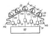
- FIG. 1shows an exemplary antenna system 10 for purposes of explaining the principles of the present invention.
- the systemincludes at least one dynamically variable beamwidth and variable scan angle antenna 12 .
- the antenna 12comprises a plurality of spaced-apart active radiating columns 28 .
- each column 28includes a dual dipole element 26 having respective dipoles 26 a and 26 b.
- each column 28may electrically couple to a respective pair 40 of phase shifters 40 a,b of a plurality of continuously adjustable mechanical phase shifters.
- phase shifter 40 a of a respective phase shifter pair 40may connect to a first dipole 26 a of each dual dipole element 26 of a radiating column 28
- phase shifter 40 b of the phase shifter pairmay connect to a second dipole 26 b of each dual dipole element 26 .
- each phase shifter 40 a,bis positioned so as to affect a respective polarization of the signal propagating from each column 28 .
- each phase shifter 40 a,bis positioned between a column signal node 50 and a feed node 54 so as to affect the beamwidth and/or azimuth scan angle of the signal through phase variance.
- each phase shifter pair 40includes an independently and remotely controlled drive 42 .
- the phase shifter pair 40 of a respective column 28couples to a common drive 42 for material and operating considerations. For instance, such common control may simplify user control of wave propagation.
- the beamwidth and the azimuth scan angleare correlated to phase shifts and/or power distributions accomplished between the respective column nodes 50 and the feed node 54 .
- the beamwidth and/or azimuth scan anglemay be varied such as in response to signal from a control station so as to broaden or narrow the width of the beam and/or move the center of the beam left or right.
- phase shifters 40 a,bare independently operable to vary the phase shift, i.e., the phase of an electrical signal, between the respective column signal nodes 50 and respective feed nodes 54 , to thereby vary the beamwidth and/or azimuth scan angle of the beam defined by the plurality of active radiating columns 28 .
- a plurality of cascading power dividers contained within an azimuth feed network 46 a and 46 bmay work in tandem with or separately from the phase shifters 40 a,b to similarly affect the beamwidth and/or azimuth scan angle. That is, the power dividers of one embodiment are positioned between the column signal node 50 and the feed node 54 . Such positioning allows the power dividers to affect the beamwidth and/or azimuth scan angle of the signal through power variance. To facilitate such signal pattern control, many or all of the power dividers may include an independently controlled drive. Where desired, the drive control of the power dividers is remotely controlled for operability and performance reasons.
- the dual dipole elements 26 within each respective column 28are electromagnetically coupled, such as through elevation feed networks comprising stripline or microstrip conductors, as shown at reference numeral 30 on circuit board 52 in FIG. 2.
- the dual dipole elements 26may also mount on the circuit board 52 .
- the dual dipole elements 26 within a column 28may be coupled using air stripline and/or one or more power dividers having associated cabling (all of which are not shown), eliminating the need for a circuit board.
- the dynamically variable beamwidth antenna 12 shown in FIG. 1includes five columns 28 , each column 28 having ten dual dipole elements 26 , embodiments of the present invention may be configured using any desired number of columns and elements without departing from the spirit of the present invention.
- dual dipole elementshave particular application within certain embodiments of the present invention, one of skill in the art will appreciate that other embodiments may include any radiating element, to include single or multi-pole elements.
- each active radiating column 28electrically associated with each active radiating column 28 is a respective pair of continuously adjustable mechanical phase shifters 40 a,b .
- Each mechanical phase shifter pair 40typically couples to a respective, independent and remotely controlled drive 42 .
- Each respective mechanical phase shifter 40 a,b of a pair 40is directly electrically connected, such as by coaxial cables 44 and/or striplines 30 , to the dual dipole elements 26 of a respective active radiating column 28 .
- Such direct electrical connectionsdefine column signal nodes 50 .
- respective pairs of phase shifterscorrelate to different polarizations (e.g., plus and minus 45 degrees) and couple to respective radiating columns of the antenna.
- the beamwidth and/or azimuth scan angle of each beammay also be adjusted remote from the antenna where desired via a remote phase shifter interface.
- Each mechanical phase shifter 40 a,bmay also electrically couple to a plurality of power dividers included within a respective azimuth feed network 46 , which defines a respective feed node 54 .
- the mechanical phase shifters 40 a,bcouple to intermediate column signal nodes 50 and feed node 54 .
- a radio frequency (RF) connection 48couples signals to and from feed node 54 as will be readily appreciated.
- Mechanical phase shifters 40 a,bmay be adjusted independently to vary the phase of the signal emanating from columns 28 .
- an exemplary azimuth feed network 46may include a circuit board in the form of traces, associated cabling, and/or other structures to provide a serial or corporate feed, as will be appreciated by those skilled in the art.
- the plurality of power dividers of the azimuth feed network 46may apportion power input at nodes 54 among the active radiating columns 28 via the phase shifters 40 a,b to vary the beamwidth and azimuth scan angle of a signal radiating from the antenna 12 .
- the plurality of power dividers of each azimuth feed network 46may combine power incident on elements 26 in the radiating columns 28 to be received at a respective feed node 54 .
- An exemplary power dividermay comprise one or more couplers, as well as an inline phase delay device.
- a reflective-type phase delay devicemay alternatively and/or additionally be used.
- each power divider 41may include a pair of hybrid directional couplers.
- a hybrid directional coupleris a four port electromagnetic device that is configured to provide an output that is proportional solely to power incident from a source.
- a hybrid directional couplerwill divide the incident power from a source at one port between two other ports at quadrature phase. The relative power at each other port with respect to the incident power will be known for a given set of impedances, each coupled to a port of the device.
- Quadrature hybrid directional couplersare commonly used in communications equipment. Such couplers allow a sample of a communications signal input at an input port and output at an output or “direct” port, to be taken from the signal at third or “coupled” port. No signal emerges from the fourth or “isolated” port.
- a directional couplermay discern between a signal input at the input port and signal input at the direct port. Such ability to discern is particularly useful when, for example, a coupler is coupled intermediate an RF amplifier and an antenna. In such a configuration, the output of the RF amplifier may be monitored independently from that of a signal reflected from a mismatched antenna.
- Such a monitored signalmay be used to control the gain, e.g., automatic gain control (AGC), or reduce the distortion of the RF amplifier.
- AGCautomatic gain control
- a suitable power divider for purposes of this specificationmay comprise any device capable of apportioning and/or combining power as appropriate.
- FIG. 2shows a power divider configuration 148 suited for explaining the principles of the present invention.
- a configuration of power dividers 41 similar to that of FIG. 2could be included within each of the azimuth feed networks 46 of FIG. 2 to provide beamwidth and azimuth scan angle adjustment.
- the power divider configuration 148may couple to each column 28 .
- the configurationmay couple to a mechanical phase shifter 43 a - e of each (column 28 ) phase shifter pair that corresponds to a specific polarization of a dual dipole element 26 .
- one or more of the power dividers 41may alternatively couple to a respective dual dipole element 26 without first coupling to a variable phase shifter 43 a - e .
- Implementation of such a configurationmay be particularly applicable where the relative phase of the respective dual dipole element 26 remains constant. Such a scenario is discussed below in greater detail.
- a first power divider 41 acouples to respective antenna elements of an antenna 12 via respective phase shifters 42 .
- a suitable antenna element of the antenna 12may comprise any device configured to receive and/or transmit electromagnetic radiation, to include the above discussed dual dipole elements of the antenna 12 .
- each antenna element 26may be included within respective radiating columns 28 .
- a second power divider 41 bcouples to third and fourth antenna elements, respectively, of the antenna 12
- a third power divider 41 ccouples to both the first power divider 41 a and a fifth antenna element of the antenna's plurality of antenna elements 26
- a fourth power divider 41 dcompletes the distributed configuration 148 by coupling to both the second and third power dividers, 41 b and c .
- the distributed power dividers 41 of the azimuth feed network 46may couple to the antenna 12 via mechanical phase shifters 40 a,b as shown in FIG. 1.
- Mechanical phase shifters 40 a,b and their drivesmount directly adjacent their respective radiating column 28 of antenna 12 . Such mounting furthers the utility of the azimuth feed networks 46 in antenna 12 , allowing a single RF connection 48 per azimuth feed network 46 to antenna 12 , thereby reducing the number of cables that must traverse tower 14 .
- Each drive 42is independently and remotely controlled using signal(s) coupled through a cable, an optical link, an optical fiber, or a radio signal as indicated at reference numeral 24 .
- each drive 42may have its own respective signal.
- signals 24may be multiplexed as provided by interface 59 .
- a common drive 42may service both phase shifters 40 a,b of a respective phase shifter pair 40 . Such mutual coupling may simplify signal adjustment processes for a user where desired.
- each mechanical phase shifter 40 a,bmay be used to vary the phase or delay of a signal between feed node 54 and the respective column node 50 for a given polarization. Further, phase shifters 40 a,b may also be used to vary or stagger the phase between the respective nodes 50 , thereby varying the phase between the radiating columns 28 a - e . The differences in phase between the radiating columns 28 a - e , associated with transmission and reception of signals from antenna 12 determines the beamwidth and/or azimuth scan angle of antenna 12 .
- a phase delaywill be added to or subtracted from the radiating columns 28 such that a greater amount of change in delay is applied to the outer most columns.
- a mathematical equationmay be derived that relates the phase differences between the radiating columns 28 a - e in varying the beamwidth.
- One such equationmay be a second order linear equation, or a quadratic equation.
- a phase delaymay be added to one end of the columns 28 in the plurality of columns while a phase delay may be subtracted from those columns at the other end.
- One mathematical equation that relates the phase differences between the radiating columns 28 in varying the azimuth scan angleis a first order linear equation.
- equationssuch as higher order polynomial equations, relating the differences in phase between the radiating columns 28 may also be used and/or derived.
- a combination of equations each relating phase differences between the radiating columns 28such as a linear and a quadratic equation, may be used in varying both beamwidth and azimuth scan angle.
- the beamwidth of such an antennamay be varied from approximately 30° to approximately 180° for each beam, depending on the arrangement of the columns 28 , for example, while the azimuth scan angle may be varied by approximately +/ ⁇ 50° for each beam.
- the ability to vary the azimuth scan angledepends on the beamwidth selected. For example, if a beamwidth of 40° is selected, the azimuth scan angle may be varied +/ ⁇ 50°. However, if a beamwidth of 90° is selected, the azimuth scan angle may be limited such as to +/ ⁇ 40°. Those skilled in the art will appreciate that other beamwidths may be selected that correspondingly affect the range of variability of the azimuth scan angle.
- the phase shifters 40 a,bare independently and remotely operable to vary the beamwidth and/or azimuth scan angle of antenna 12 (in tandem or independent of the adjustable power dividers 41 ). Moreover, such an adjustment in beamwidth and/or azimuth scan angle is possible while antenna 12 is in operation, i.e., dynamically.
- one or more of the columns 28may be fixed in phase with respect to the signal transmitted by or received using the antenna 12 , thereby varying the phase of only those remaining columns 28 .
- a pair 40 of phase shifters 40 a,b along with their associated drive 42 and control signal 24could be eliminated as indicated by connection 58 (shown in dashed line).
- connection 58shown in dashed line.
- a number of such connections 58would effectively short nodes 50 and 54 , such that the columns 28 outnumber phase shifter pairs, or even phase shifters 41 .
- phase shifters 41may then vary the signals at nodes 50 with respect to the signal at the shorted nodes 58 to vary the beamwidth and/or azimuth scan angle of antenna 12 . Elimination of a phase shifter 41 and its associated drive reduces the cost of the antenna 12 .
- Those skilled in the artwill recognize that other embodiments of the present invention may be constructed using differing numbers of columns 28 , phase shifters 40 a,b and/or power dividers 41 .
- exemplary mechanical phase shifters 40 a,bmay be linear, reflective-type or rotary. Either type of phase shifter may be coupled to a drive 42 , such as a motor or other suitable means, to move a piece of dielectric material relative to a conductor within the phase shifter, to thereby vary the insertion phase of a signal between input and output ports of the device.
- a drive 42such as a motor or other suitable means
- FIG. 3an exploded view of an exemplary rotary mechanical phase shifter 60 including a drive, or motor, 42 is illustrated.
- Drive 42is responsive to a control signal 24 and includes a shaft 62 .
- Shaft 62may be coupled directly to the mechanical phase shifter 60 , as shown in FIG. 3, or through a gearbox, pulleys, etc. (not shown).
- Shaft 62is coupled to a high dielectric constant material 64 that is rotated, as indicated by arrow 66 , in a housing 78 .
- Rotary mechanical phase shifter 60varies the phase shift between input and output ports 68 , 70 by rotating 66 high dielectric constant material 64 on both sides of stripline center conductor 72 .
- the high dielectric constant material 64has a slower propagation constant than air, and thus increases electrical delay of a signal carried by conductor 72 .
- Slots 74 , 76provide a gradient in the dielectric constant.
- a plurality of holes or other apertures in the high dielectric constant material 64may be used to provide a gradient in the dielectric constant.
- the amount of delay, or phase shiftis determined by the relative length of conductor 72 covered above and/or below by the high dielectric constant material 64 .
- Housing 78may be constructed using aluminum or some other suitably rigid material.
- Linear mechanical phase shifter 80couples to a drive, such as a motor 42 , having a shaft 82 .
- Shaft 82couples through a mechanism, such as a worm gear 84 , to slab(s) 86 of a high dielectric constant material within the phase shifter 80 .
- drive 42through shaft 82 and worm gear 84 , moves high dielectric constant material 86 linearly relative to a conductor 88 , as indicated at by arrow 90 .
- the high dielectric constant material 86has a slower propagation constant than air, and thus increases the electrical delay of a signal carried by conductor 88 .
- Slots 96 , 98provide a gradient in the dielectric constant.
- the amount of delay, or phase shift,is controlled by the relative length of the conductor 88 that is covered, above and/or below, by the high dielectric constant material 86 .
- the linear position of the high dielectric constant material 86 relative to conductor 88determines the phase of a signal between ports 92 and 94 of the phase shifter 80 .
- linear phase shiftermay be found in U.S. Pat. No. 3,440,573, the disclosure of which is incorporated herein by reference in its entirety.
- Yet another example of a linear phase shiftermay be found in U.S. Pat. No. 6,075,424, the disclosure of which is also incorporated herein by reference in its entirety.
- the number of columns, the spacing between the columns, and the relative position of the columns in an antennamay determine the ability to vary beamwidth and/or azimuth scan angle as desired.
- FIGS. 5 - 7illustrate top views of three antennas having particular column arrangements suited for explaining the principles of the present invention. Those skilled in the art will appreciate that the present invention is not limited to any one of these arrangements, they are merely shown by way of example.
- FIG. 5shows an antenna having an irregular or linearly segmented arrangement of five active radiating columns 28 .
- Each column 28contains a plurality of dual dipole elements 26 .
- the dual dipole elements 26 in each radiating column 28comprise conductive elements on one or more circuit boards 150 in each column 28 .
- the circuit boards 150mount to one or more sheet metal reflectors 138 .
- the reflectors 138include one or more holes or apertures (not shown) for electrically coupling to dual dipole elements 26 in radiating columns 28 .
- the dual dipole elements 26 within each active radiating column 28are electromagnetically coupled using elevation feed networks 30 as described in conjunction with FIG. 1. As such, the elevation feed networks are located behind the reflectors 138 . For example, if ten active radiating elements 26 were used per active radiating column 28 , then ten cables from each elevation feed network 30 may be used to electromagnetically couple the dual dipole elements 26 within each column 28 .
- the dual dipole elements 26 within each respective column 28may be electromagnetically coupled using a combination of stripline or microstrip conductors located on circuit boards 150 and a plurality of remotely controlled, adjustable power dividers having associated cabling, located behind reflectors 138 .
- power variation provided by the adjustable power dividers positioned within block 148allows users to tailor the beamwidth and azimuth scan angle of the signal pattern.
- Antennaincludes a plurality of mechanical phase shifters 40 a,b and power dividers 41 as previously described in conjunction with FIG. 1 and as indicted by reference numeral 148 in both FIGS. 1 and 5.
- Columns 28may substantially equally spaced (by a distance 140 , typically at about 0.4 wavelength intervals), columns 28 being arranged in substantially a first plane 142 . Columns 28 are substantially equally spaced 140 from each other. The columns 28 are further set back a distance 144 and 145 , respectfully, from the first plane 142 .
- Such an irregular or linearly segmented arrangementallows beam 32 broadening, typically associated with an arcuate, curvilinear or cylindrical arrangement as discussed below in detail, while reducing the mutual coupling between adjacent dual dipole elements in adjacent columns.
- exemplary dual dipole elements 26may bow, angle, or “droop,” inwardly. This bowed feature may minimize space required by the elements, allowing for optimum space efficiencies.
- the bowed configuration of the elementsmay further offer advantageous propagation characteristics of their own. For instance, the bowed shape may affect the propagation pattern of the signal transmitted from the columns in a predictable and desirable manner, such as beamwidth equalization. While the dual dipole elements 26 of FIG. 5 have dual slant polarizations, other embodiments that are consistent with the invention could alternatively use any orthogonal polarization.
- the choke 141 a and 141 b and ground plane structures of the antenna 12may be modified to meet specific application requirements.
- the choke 141 a and 141 b and ground planesmay be optimized to mitigate radiation from front to back.
- an antenna having an arcuate, curvilinear or cylindrical arrangement of active radiating columns 28is illustrated.
- the antennacomprises a plurality of dual dipole elements 26 arranged into the eight substantially equally spaced (by a distance 124 ) active radiating columns 28 by mounting the elements 26 to a similarly arcuate, curvilinear or cylindrical curved reflector 126 having a stripline or microstrip traces (not shown) for coupling the respective dual dipole elements 26 with each column 28 .
- the antennafurther comprises pairs of continuously adjustable mechanical phase shifters 40 a,b , each coupled to a respective independently remotely controlled drive 42 and a plurality of power dividers 46 .
- control signals 24actuate drives 42 adjusting the mechanical phase shifters 40 a,b so as to dynamically vary the beamwidth and/or azimuth scan angle of antenna as described hereinbefore.
- the plurality of power dividers 46may function to vary power delivered to each phase shifter. In this manner, the power variance further functions to vary the beamwidth and/or azimuth scan angle of the antenna.
- the arcuate, curvilinear or cylindrical arrangement of active radiating columns 28 a - h shown in FIG. 6may allow for wider beam broadening than that of a linear arrangement described below.
- the spacing 124 of columns 28such as advantageously on substantially quarter (0.25) wavelength intervals of the center frequency of the antenna, reduces the antenna side lobes at the expense of increased mutual coupling between adjacent dual dipole elements 26 in adjacent columns 28 .
- the antennaincludes four substantially equally spaced (by a distance 102 ) active radiating columns 28 , each containing a plurality of dual dipole elements 26 mounted to a circuit board, or reflector, 104 .
- the dual dipole elements 26 within each respective column 28are coupled using stripline, microstrip, or air stripline (none of which are shown), as described hereinabove.
- the active radiating columns 28are directly electrically connected to respective pairs 40 of continuously adjustable mechanical phase shifters 40 a,b , each pair 40 coupled to a respective independently remotely controlled drive 42 (although at least one of the phase shifters 40 a,b may be eliminated as discussed earlier in connection with FIG. 2).
- Each phase shifter 40 a,b of the illustrated embodiment of FIG. 8also couples to a network of distributed power dividers 46 .
- the power dividers 46may vary the power supplied to respective phase shifters, thereby altering the beamwidth and/or scan angle of the antenna system.
- the beamwidth and/or scan anglemay be further configured via control signals 24 that actuate the drives 42 .
- the drivesare configured to adjust the mechanical phase shifters 40 a,b so as to dynamically vary the beamwidth and/or azimuth scan angle of antenna independently from or in tandem with the power dividers 46 as described hereinbefore.
- phase shifters and power dividersmay complement each other to synergistically produce superior signal pattern control
- different embodimentsmay include and/or use only one of variable phase shifters or power dividers as described herein to vary the beamwidth and/or scan angle.
- dual dipole elementsprovides particular utility in certain applications may use single pole radiating elements.
- each column 28 of the antenna systemincludes dual dipole elements 26 .
- each column 28accommodates two polarizations useful in signal diversity applications.
- the antenna systemcouples two independent phase shifters to each column 28 .
- a separate phase shiftermay adjust the bandwidth and/or azimuth scan angle for each, diversely polarized signal.
- each pair of phase shifters corresponding to respective column polarizationsmay gang together at a common drive 42 for operating considerations.
- separate drivesmay control each phase shifter 40 a,b , while still providing signal diversity.
- an embodiment of the present inventionmay capitalize on the independent nature of each phase shifter 40 a,b by combining them with a cascading series of adjustable power dividers.
- a network of power dividers 41may couple to each phase shifter 40 a,b associated with a particular polarization.
- two separate networks of power dividers 41may vary energy delivered to the antenna 12 in such a manner as to further affect the beamwidth and or azimuth scan angle of each polarized signal.
- the power dividers 41may thus work separately or in concert with the phase shifters 40 a,b to provide greater wave propagation control.
- the radiating columns 28may include dual dipole antenna elements 26 as discussed below in greater detail.
- the dual dipole antenna elements 26provide signal diversity. That is, the dual dipole antenna elements allow both simultaneously transmitted signals to be received by the same, dual dipole element. This configuration obviates the above discussed requirement of prior art systems for multiple antennas. In so doing, an embodiment of the present invention can receive, transmit and dynamically configure signals without burdening users with many space and maintenance complications that plague conventional antenna systems.
- an antenna for purposes of this specificationmay be utilized as a transmit and/or receive antenna independently or simultaneously, thereby broadening or narrowing the transmit or receive beamwidth and/or steering the beam center accordingly as desired.
- the present inventionis not limited in the type of radiating elements used. Any type of radiating elements may be used, as appropriate.
- the inventionis also not limited in the number of rows of radiating elements, nor does it necessitate rows, per se.
- the inventionmay also be used with or without antenna downtilt, either mechanical or electrical.
- the azimuth distribution network described hereinmay incorporate the ability to vary the amplitude of a signal at the respective column signal nodes furthering the ability to vary the beamwidth and/or azimuth scan angle. Still further, although the number of columns in relation to phase shifter pairs and/or power dividers are disclosed above, other relationships can be realized in accordance with the principles of the present invention. Those skilled in the art will also appreciate that an antenna in accordance with the present invention may be mounted in any location and is not limited to those mounting locations described herein. The invention in its broader aspects is therefore not limited to the specific details, representative apparatus and method, and illustrative examples shown and described. Accordingly, departures may be made from such details without departing from the spirit and scope of applicants' general inventive concept.
Landscapes
- Engineering & Computer Science (AREA)
- Computer Networks & Wireless Communication (AREA)
- Variable-Direction Aerials And Aerial Arrays (AREA)
Abstract
Description
- This is a continuation-in-part of presently pending U.S. application Ser. No. 10/255,747, entitled “Dynamically Variable Beamwidth and Variable Azimuth Scanning Antennas,” which was filed by on Sep. 26, 2002, the disclosure of which is hereby incorporated by reference in its entirety.[0001]
- This invention relates generally to antennas, and more particularly to a mechanism for dynamically varying the beamwidth and azimuth scan angle of such antennas.[0002]
- Antenna construction generally includes a plurality of antenna columns defining a signal beamwidth and azimuth scan angle. The beamwidth of an antenna may be modified by varying the phase of an electrical signal applied to the columns. Advancements in antenna technologies include providing each antenna column with an individually-coupled, mechanical phase shifter. Systems having a phase shifter dedicated to each column of an antenna allow improved beamwidth and azimuth scan angle control.[0003]
- While antenna configurations having individually-coupled phase shifters provide increased wave propagation control, still greater beamwidth and azimuth scan angle variability is desired. Additionally, an individually-coupled phase shifter configuration may fail to provide sufficient control for certain signal diversity applications, such as where dual dipole elements are desired. Signal diversity generally involves separating signals for subsequent processing. For instance, two signals having different polarizations may be combined upon transmittal so that their aggregate signal strength is sufficient to allow the composite signal to reach respectively polarized antenna columns.[0004]
- Antennas having dual dipole elements allow a single column to receive/transmit both polarizations, avoiding maintenance, space and aesthetic drawbacks associated with greater numbers of single pole antennas. However, diversity benefits associated with dual dipole elements may remain unrealized in conjunction with the individually-coupled phase shifter configuration incorporated herein, which would facilitate improved propagation control in only one of the two polarizations.[0005]
- Consequently, there is a need to provide wider dynamic wave propagation control. Further improvements are also possible where each column of an antenna includes multiple poles.[0006]
- The accompanying drawings, which are incorporated in and constitute a part of this specification, illustrate embodiments of the invention and, together with the detailed description given below, serve to explain the principles of the invention.[0007]
- FIG. 1 is a schematic diagram of the dynamically variable beamwidth and/or variable azimuth scan angle antenna for purposes of explaining the principles of the present invention.[0008]
- FIG. 2 is a block diagram of an azimuth scanning network suited for explaining the principles of the present invention.[0009]
- FIG. 3 is an exploded view of an exemplary rotary mechanical phase shifter including a drive.[0010]
- FIG. 4 is an exploded view of an exemplary linear mechanical phase shifter including a drive.[0011]
- FIG. 5 is a top view of an antenna having an irregular or linearly segmented column arrangement.[0012]
- FIG. 6 is a top view of an antenna having a curvilinear column arrangement.[0013]
- FIG. 7 is a top view of an antenna having a linear column arrangement.[0014]
- FIG. 1 shows an exemplary antenna system[0015]10 for purposes of explaining the principles of the present invention. The system includes at least one dynamically variable beamwidth and variable
scan angle antenna 12. Theantenna 12, in turn, comprises a plurality of spaced-apart activeradiating columns 28. Where desired, eachcolumn 28 includes adual dipole element 26 having respective dipoles26aand26b. - As shown in FIG. 1, each[0016]
column 28 may electrically couple to arespective pair 40 ofphase shifters 40a,bof a plurality of continuously adjustable mechanical phase shifters. As explained below in greater detail,phase shifter 40aof a respectivephase shifter pair 40 may connect to a first dipole26aof eachdual dipole element 26 of aradiating column 28, andphase shifter 40bof the phase shifter pair may connect to a second dipole26bof eachdual dipole element 26. As such, each phase shifter40a,bis positioned so as to affect a respective polarization of the signal propagating from eachcolumn 28. - More particularly, each phase shifter[0017]40a,bis positioned between a
column signal node 50 and afeed node 54 so as to affect the beamwidth and/or azimuth scan angle of the signal through phase variance. To further facilitate signal pattern control, eachphase shifter pair 40 includes an independently and remotely controlleddrive 42. In the embodiment, thephase shifter pair 40 of arespective column 28 couples to acommon drive 42 for material and operating considerations. For instance, such common control may simplify user control of wave propagation. - The beamwidth and the azimuth scan angle are correlated to phase shifts and/or power distributions accomplished between the[0018]
respective column nodes 50 and thefeed node 54. In accordance with the principles of the present invention and as will be described hereinafter, the beamwidth and/or azimuth scan angle may be varied such as in response to signal from a control station so as to broaden or narrow the width of the beam and/or move the center of the beam left or right. - To that end, the[0019]
phase shifters 40a,bare independently operable to vary the phase shift, i.e., the phase of an electrical signal, between the respectivecolumn signal nodes 50 andrespective feed nodes 54, to thereby vary the beamwidth and/or azimuth scan angle of the beam defined by the plurality of activeradiating columns 28. - A plurality of cascading power dividers contained within an[0020]
azimuth feed network 46aand46bmay work in tandem with or separately from thephase shifters 40a,bto similarly affect the beamwidth and/or azimuth scan angle. That is, the power dividers of one embodiment are positioned between thecolumn signal node 50 and thefeed node 54. Such positioning allows the power dividers to affect the beamwidth and/or azimuth scan angle of the signal through power variance. To facilitate such signal pattern control, many or all of the power dividers may include an independently controlled drive. Where desired, the drive control of the power dividers is remotely controlled for operability and performance reasons. - As shown in FIG. 2, the[0021]
dual dipole elements 26 within eachrespective column 28 are electromagnetically coupled, such as through elevation feed networks comprising stripline or microstrip conductors, as shown atreference numeral 30 on circuit board52 in FIG. 2. Thedual dipole elements 26 may also mount on the circuit board52. Alternatively, thedual dipole elements 26 within acolumn 28 may be coupled using air stripline and/or one or more power dividers having associated cabling (all of which are not shown), eliminating the need for a circuit board. Although the dynamicallyvariable beamwidth antenna 12 shown in FIG. 1 includes fivecolumns 28, eachcolumn 28 having tendual dipole elements 26, embodiments of the present invention may be configured using any desired number of columns and elements without departing from the spirit of the present invention. Moreover, while dual dipole elements have particular application within certain embodiments of the present invention, one of skill in the art will appreciate that other embodiments may include any radiating element, to include single or multi-pole elements. - With further reference to FIG. 1, electrically associated with each active[0022]
radiating column 28 is a respective pair of continuously adjustablemechanical phase shifters 40a,b. Each mechanicalphase shifter pair 40 typically couples to a respective, independent and remotely controlleddrive 42. Each respectivemechanical phase shifter 40a,bof apair 40 is directly electrically connected, such as bycoaxial cables 44 and/orstriplines 30, to thedual dipole elements 26 of a respective activeradiating column 28. Such direct electrical connections definecolumn signal nodes 50. - In one embodiment, respective pairs of phase shifters correlate to different polarizations (e.g., plus and minus 45 degrees) and couple to respective radiating columns of the antenna. The beamwidth and/or azimuth scan angle of each beam may also be adjusted remote from the antenna where desired via a remote phase shifter interface.[0023]
- Each mechanical phase shifter[0024]40a,bmay also electrically couple to a plurality of power dividers included within a respective azimuth feed network46, which defines a
respective feed node 54. Thus, as illustrated in the schematic diagram of FIG. 1, themechanical phase shifters 40a,bcouple to intermediatecolumn signal nodes 50 andfeed node 54. A radio frequency (RF) connection48 couples signals to and fromfeed node 54 as will be readily appreciated.Mechanical phase shifters 40a,bmay be adjusted independently to vary the phase of the signal emanating fromcolumns 28. - In addition to the plurality of power dividers, an exemplary azimuth feed network[0025]46 may include a circuit board in the form of traces, associated cabling, and/or other structures to provide a serial or corporate feed, as will be appreciated by those skilled in the art. The plurality of power dividers of the azimuth feed network46 may apportion power input at
nodes 54 among the activeradiating columns 28 via thephase shifters 40a,bto vary the beamwidth and azimuth scan angle of a signal radiating from theantenna 12. Conversely, in receiving a signal, the plurality of power dividers of each azimuth feed network46 may combine power incident onelements 26 in theradiating columns 28 to be received at arespective feed node 54. - An exemplary power divider may comprise one or more couplers, as well as an inline phase delay device. One of skill in the art should appreciate that a reflective-type phase delay device may alternatively and/or additionally be used. Where desired, each power divider[0026]41 may include a pair of hybrid directional couplers. As in known in the art, a hybrid directional coupler is a four port electromagnetic device that is configured to provide an output that is proportional solely to power incident from a source. For a given bandwidth, a hybrid directional coupler will divide the incident power from a source at one port between two other ports at quadrature phase. The relative power at each other port with respect to the incident power will be known for a given set of impedances, each coupled to a port of the device.
- Quadrature hybrid directional couplers are commonly used in communications equipment. Such couplers allow a sample of a communications signal input at an input port and output at an output or “direct” port, to be taken from the signal at third or “coupled” port. No signal emerges from the fourth or “isolated” port. When appropriately designed, a directional coupler may discern between a signal input at the input port and signal input at the direct port. Such ability to discern is particularly useful when, for example, a coupler is coupled intermediate an RF amplifier and an antenna. In such a configuration, the output of the RF amplifier may be monitored independently from that of a signal reflected from a mismatched antenna. Moreover, such a monitored signal may be used to control the gain, e.g., automatic gain control (AGC), or reduce the distortion of the RF amplifier. In any case, a suitable power divider for purposes of this specification may comprise any device capable of apportioning and/or combining power as appropriate.[0027]
- FIG. 2 shows a[0028]
power divider configuration 148 suited for explaining the principles of the present invention. As illustrated, a configuration of power dividers41 similar to that of FIG. 2 could be included within each of the azimuth feed networks46 of FIG. 2 to provide beamwidth and azimuth scan angle adjustment. Thus, thepower divider configuration 148 may couple to eachcolumn 28. For instance, the configuration may couple to a mechanical phase shifter43a-eof each (column28) phase shifter pair that corresponds to a specific polarization of adual dipole element 26. - As shown in FIG. 2, one or more of the power dividers[0029]41 may alternatively couple to a respective
dual dipole element 26 without first coupling to a variable phase shifter43a-e. Implementation of such a configuration may be particularly applicable where the relative phase of the respectivedual dipole element 26 remains constant. Such a scenario is discussed below in greater detail. - In any case, changes in power delivered to respective phase shifters[0030]43a-emay bring about variation in beamwidth and azimuth scan angle for the specific polarization associated with the respective phase shifters43a-e. Where
single dipole elements 26 are alternatively used, one of skill in the art will appreciate that a single configuration/azimuth feed network46 may adequately service all columns. Moreover, an embodiment of the present invention may include more or fewer power dividers41 while remaining in accordance with the principles of the present invention. - Turning more particularly to FIG. 2, a[0031]
first power divider 41acouples to respective antenna elements of anantenna 12 viarespective phase shifters 42. As discussed herein, a suitable antenna element of theantenna 12 may comprise any device configured to receive and/or transmit electromagnetic radiation, to include the above discussed dual dipole elements of theantenna 12. In the context of FIG. 1, eachantenna element 26 may be included withinrespective radiating columns 28. - As shown in FIG. 2, a[0032]
second power divider 41bcouples to third and fourth antenna elements, respectively, of theantenna 12, while a third power divider41ccouples to both thefirst power divider 41aand a fifth antenna element of the antenna's plurality ofantenna elements 26. Finally, a fourth power divider41dcompletes the distributedconfiguration 148 by coupling to both the second and third power dividers,41bandc. By adjusting the power distribution setting of one or all of the power dividers41 in the azimuth feed network46, a user may modify the beamwidth and/or azimuth scan angle of a signal propagating from theantenna 12. - Where desired, the distributed power dividers[0033]41 of the azimuth feed network46 may couple to the
antenna 12 viamechanical phase shifters 40a,bas shown in FIG. 1.Mechanical phase shifters 40a,band their drives mount directly adjacent theirrespective radiating column 28 ofantenna 12. Such mounting furthers the utility of the azimuth feed networks46 inantenna 12, allowing a single RF connection48 per azimuth feed network46 toantenna 12, thereby reducing the number of cables that must traversetower 14. - Each[0034]
drive 42 is independently and remotely controlled using signal(s) coupled through a cable, an optical link, an optical fiber, or a radio signal as indicated at reference numeral24. As shown in FIG. 1, each drive42 may have its own respective signal. Using conventional means of addressing, signals24 may be multiplexed as provided by interface59. As discussed herein, acommon drive 42 may service bothphase shifters 40a,bof a respectivephase shifter pair 40. Such mutual coupling may simplify signal adjustment processes for a user where desired. - As such, each[0035]
mechanical phase shifter 40a,bmay be used to vary the phase or delay of a signal betweenfeed node 54 and therespective column node 50 for a given polarization. Further,phase shifters 40a,bmay also be used to vary or stagger the phase between therespective nodes 50, thereby varying the phase between the radiatingcolumns 28a-e. The differences in phase between the radiatingcolumns 28a-e, associated with transmission and reception of signals fromantenna 12 determines the beamwidth and/or azimuth scan angle ofantenna 12. - Generally, in varying the beamwidth of such an[0036]
antenna 12, a phase delay will be added to or subtracted from the radiatingcolumns 28 such that a greater amount of change in delay is applied to the outer most columns. A mathematical equation may be derived that relates the phase differences between the radiatingcolumns 28a-ein varying the beamwidth. One such equation may be a second order linear equation, or a quadratic equation. - Similarly, in varying the azimuth scan angle, a phase delay may be added to one end of the[0037]
columns 28 in the plurality of columns while a phase delay may be subtracted from those columns at the other end. One mathematical equation that relates the phase differences between the radiatingcolumns 28 in varying the azimuth scan angle is a first order linear equation. Those skilled in the art will appreciate that other equations, such as higher order polynomial equations, relating the differences in phase between the radiatingcolumns 28 may also be used and/or derived. Moreover, those skilled in the art will appreciate that a combination of equations each relating phase differences between the radiatingcolumns 28, such as a linear and a quadratic equation, may be used in varying both beamwidth and azimuth scan angle. - The beamwidth of such an antenna may be varied from approximately 30° to approximately 180° for each beam, depending on the arrangement of the[0038]
columns 28, for example, while the azimuth scan angle may be varied by approximately +/−50° for each beam. The ability to vary the azimuth scan angle depends on the beamwidth selected. For example, if a beamwidth of 40° is selected, the azimuth scan angle may be varied +/−50°. However, if a beamwidth of 90° is selected, the azimuth scan angle may be limited such as to +/−40°. Those skilled in the art will appreciate that other beamwidths may be selected that correspondingly affect the range of variability of the azimuth scan angle. - Thus, according to the principles of the present invention, and as illustrated in FIG. 1, the[0039]
phase shifters 40a,bare independently and remotely operable to vary the beamwidth and/or azimuth scan angle of antenna12 (in tandem or independent of the adjustable power dividers41). Moreover, such an adjustment in beamwidth and/or azimuth scan angle is possible whileantenna 12 is in operation, i.e., dynamically. - Since the difference in phase between[0040]
columns 28 affects the beamwidth and/or azimuth scan angle of such an antenna, one or more of thecolumns 28 may be fixed in phase with respect to the signal transmitted by or received using theantenna 12, thereby varying the phase of only those remainingcolumns 28. For example and as shown in FIG. 1, apair 40 ofphase shifters 40a,balong with their associateddrive 42 and control signal24, could be eliminated as indicated by connection58 (shown in dashed line). A number ofsuch connections 58 would effectivelyshort nodes columns 28 outnumber phase shifter pairs, or even phase shifters41. - The remaining phase shifters[0041]41 may then vary the signals at
nodes 50 with respect to the signal at the shortednodes 58 to vary the beamwidth and/or azimuth scan angle ofantenna 12. Elimination of a phase shifter41 and its associated drive reduces the cost of theantenna 12. Those skilled in the art will recognize that other embodiments of the present invention may be constructed using differing numbers ofcolumns 28,phase shifters 40a,band/or power dividers41. - As discussed herein, exemplary[0042]
mechanical phase shifters 40a,bmay be linear, reflective-type or rotary. Either type of phase shifter may be coupled to adrive 42, such as a motor or other suitable means, to move a piece of dielectric material relative to a conductor within the phase shifter, to thereby vary the insertion phase of a signal between input and output ports of the device. - Referring to FIG. 3, an exploded view of an exemplary rotary[0043]
mechanical phase shifter 60 including a drive, or motor,42 is illustrated.Drive 42 is responsive to a control signal24 and includes ashaft 62.Shaft 62 may be coupled directly to themechanical phase shifter 60, as shown in FIG. 3, or through a gearbox, pulleys, etc. (not shown).Shaft 62 is coupled to a high dielectricconstant material 64 that is rotated, as indicated byarrow 66, in ahousing 78. - Rotary[0044]
mechanical phase shifter 60 varies the phase shift between input andoutput ports constant material 64 on both sides ofstripline center conductor 72. The high dielectricconstant material 64 has a slower propagation constant than air, and thus increases electrical delay of a signal carried byconductor 72.Slots constant material 64 may be used to provide a gradient in the dielectric constant. The amount of delay, or phase shift, is determined by the relative length ofconductor 72 covered above and/or below by the high dielectricconstant material 64. Thus, therotation 66 of high dielectricconstant material 64 relative toconductor 72 varies the phase of a signal betweenports phase shifter 60.Housing 78 may be constructed using aluminum or some other suitably rigid material. - Another example of a rotary mechanical phase shifter may be found in an article entitled, “A Continuously Variable Dielectric Phase Shifter” by William T. Joines,[0045]IEEE Transactions on Microwave Theory and Techniques,August 1971, the disclosure of which is incorporated herein by reference in its entirety.
- Referring to FIG. 4, an exploded view of an exemplary linear[0046]
mechanical phase shifter 80 is illustrated. Linearmechanical phase shifter 80 couples to a drive, such as amotor 42, having ashaft 82.Shaft 82 couples through a mechanism, such as aworm gear 84, to slab(s)86 of a high dielectric constant material within thephase shifter 80. In response to signal24, drive42, throughshaft 82 andworm gear 84, moves high dielectricconstant material 86 linearly relative to aconductor 88, as indicated at byarrow 90. - The high dielectric[0047]
constant material 86 has a slower propagation constant than air, and thus increases the electrical delay of a signal carried byconductor 88.Slots conductor 88 that is covered, above and/or below, by the high dielectricconstant material 86. Thus, the linear position of the high dielectricconstant material 86 relative toconductor 88 determines the phase of a signal betweenports 92 and94 of thephase shifter 80. - Another example of linear phase shifter may be found in U.S. Pat. No. 3,440,573, the disclosure of which is incorporated herein by reference in its entirety. Yet another example of a linear phase shifter may be found in U.S. Pat. No. 6,075,424, the disclosure of which is also incorporated herein by reference in its entirety.[0048]
- In addition to the phase relationships between the columns, the number of columns, the spacing between the columns, and the relative position of the columns in an antenna may determine the ability to vary beamwidth and/or azimuth scan angle as desired.[0049]
- FIGS.[0050]5-7 illustrate top views of three antennas having particular column arrangements suited for explaining the principles of the present invention. Those skilled in the art will appreciate that the present invention is not limited to any one of these arrangements, they are merely shown by way of example.
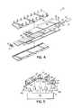
- More particularly, FIG. 5 shows an antenna having an irregular or linearly segmented arrangement of five[0051]
active radiating columns 28. Eachcolumn 28 contains a plurality ofdual dipole elements 26. Thedual dipole elements 26 in each radiatingcolumn 28 comprise conductive elements on one ormore circuit boards 150 in eachcolumn 28. Thecircuit boards 150 mount to one or more sheet metal reflectors138. Where desired, the reflectors138 include one or more holes or apertures (not shown) for electrically coupling todual dipole elements 26 in radiatingcolumns 28. - The[0052]
dual dipole elements 26 within eachactive radiating column 28 are electromagnetically coupled usingelevation feed networks 30 as described in conjunction with FIG. 1. As such, the elevation feed networks are located behind the reflectors138. For example, if tenactive radiating elements 26 were used peractive radiating column 28, then ten cables from eachelevation feed network 30 may be used to electromagnetically couple thedual dipole elements 26 within eachcolumn 28. - Alternatively, the[0053]
dual dipole elements 26 within eachrespective column 28 may be electromagnetically coupled using a combination of stripline or microstrip conductors located oncircuit boards 150 and a plurality of remotely controlled, adjustable power dividers having associated cabling, located behind reflectors138. As discussed herein, power variation provided by the adjustable power dividers positioned withinblock 148 allows users to tailor the beamwidth and azimuth scan angle of the signal pattern. Antenna includes a plurality ofmechanical phase shifters 40a,band power dividers41 as previously described in conjunction with FIG. 1 and as indicted byreference numeral 148 in both FIGS. 1 and 5. - [0054]
Columns 28 may substantially equally spaced (by adistance 140, typically at about 0.4 wavelength intervals),columns 28 being arranged in substantially a first plane142.Columns 28 are substantially equally spaced140 from each other. Thecolumns 28 are further set back a distance144 and145, respectfully, from the first plane142. Such an irregular or linearly segmented arrangement allows beam32 broadening, typically associated with an arcuate, curvilinear or cylindrical arrangement as discussed below in detail, while reducing the mutual coupling between adjacent dual dipole elements in adjacent columns. - As shown in FIG. 5, exemplary[0055]
dual dipole elements 26 may bow, angle, or “droop,” inwardly. This bowed feature may minimize space required by the elements, allowing for optimum space efficiencies. The bowed configuration of the elements may further offer advantageous propagation characteristics of their own. For instance, the bowed shape may affect the propagation pattern of the signal transmitted from the columns in a predictable and desirable manner, such as beamwidth equalization. While thedual dipole elements 26 of FIG. 5 have dual slant polarizations, other embodiments that are consistent with the invention could alternatively use any orthogonal polarization. Moreover, one of skill in the art will appreciate that thechoke 141aand141band ground plane structures of theantenna 12, as well as the relative shape of eachelement 26 may be modified to meet specific application requirements. For example, thechoke 141aand141band ground planes may be optimized to mitigate radiation from front to back. - Referring to FIG. 6, an antenna having an arcuate, curvilinear or cylindrical arrangement of[0056]
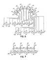
active radiating columns 28 is illustrated. The antenna comprises a plurality ofdual dipole elements 26 arranged into the eight substantially equally spaced (by a distance124)active radiating columns 28 by mounting theelements 26 to a similarly arcuate, curvilinear or cylindricalcurved reflector 126 having a stripline or microstrip traces (not shown) for coupling the respectivedual dipole elements 26 with eachcolumn 28. The antenna further comprises pairs of continuously adjustablemechanical phase shifters 40a,b, each coupled to a respective independently remotely controlleddrive 42 and a plurality of power dividers46. In operation, control signals24 actuate drives42 adjusting themechanical phase shifters 40a,bso as to dynamically vary the beamwidth and/or azimuth scan angle of antenna as described hereinbefore. Likewise, the plurality of power dividers46 may function to vary power delivered to each phase shifter. In this manner, the power variance further functions to vary the beamwidth and/or azimuth scan angle of the antenna. - The arcuate, curvilinear or cylindrical arrangement of[0057]
active radiating columns 28a-hshown in FIG. 6 may allow for wider beam broadening than that of a linear arrangement described below. The spacing124 ofcolumns 28, such as advantageously on substantially quarter (0.25) wavelength intervals of the center frequency of the antenna, reduces the antenna side lobes at the expense of increased mutual coupling between adjacentdual dipole elements 26 inadjacent columns 28. - Referring to FIG. 7, an antenna having a flat, planar, or linear arrangement of columns is illustrated. The antenna includes four substantially equally spaced (by a distance[0058]102)
active radiating columns 28, each containing a plurality ofdual dipole elements 26 mounted to a circuit board, or reflector,104. Thedual dipole elements 26 within eachrespective column 28 are coupled using stripline, microstrip, or air stripline (none of which are shown), as described hereinabove. Theactive radiating columns 28 are directly electrically connected torespective pairs 40 of continuously adjustablemechanical phase shifters 40a,b, eachpair 40 coupled to a respective independently remotely controlled drive42 (although at least one of thephase shifters 40a,bmay be eliminated as discussed earlier in connection with FIG. 2). Eachphase shifter 40a,bof the illustrated embodiment of FIG. 8 also couples to a network of distributed power dividers46. The power dividers46 may vary the power supplied to respective phase shifters, thereby altering the beamwidth and/or scan angle of the antenna system. - The beamwidth and/or scan angle may be further configured via control signals[0059]24 that actuate the
drives 42. The drives are configured to adjust themechanical phase shifters 40a,bso as to dynamically vary the beamwidth and/or azimuth scan angle of antenna independently from or in tandem with the power dividers46 as described hereinbefore. - One of skill in the art will appreciate that while the operation of the phase shifters and power dividers may complement each other to synergistically produce superior signal pattern control, different embodiments may include and/or use only one of variable phase shifters or power dividers as described herein to vary the beamwidth and/or scan angle. Similarly, while the use of dual dipole elements provides particular utility in certain applications may use single pole radiating elements.[0060]
- Thus, in operation, each[0061]
column 28 of the antenna system includesdual dipole elements 26. Thus, eachcolumn 28 accommodates two polarizations useful in signal diversity applications. To fully obtain the benefits of each polarization, the antenna system couples two independent phase shifters to eachcolumn 28. In so doing, a separate phase shifter may adjust the bandwidth and/or azimuth scan angle for each, diversely polarized signal. As discussed below, each pair of phase shifters corresponding to respective column polarizations may gang together at acommon drive 42 for operating considerations. Alternatively, separate drives may control eachphase shifter 40a,b, while still providing signal diversity. - To achieve greater wave propagation control for each polarized signal, an embodiment of the present invention may capitalize on the independent nature of each[0062]
phase shifter 40a,bby combining them with a cascading series of adjustable power dividers. As shown in FIG. 2, a network of power dividers41 may couple to eachphase shifter 40a,bassociated with a particular polarization. As such, two separate networks of power dividers41 may vary energy delivered to theantenna 12 in such a manner as to further affect the beamwidth and or azimuth scan angle of each polarized signal. The power dividers41 may thus work separately or in concert with thephase shifters 40a,bto provide greater wave propagation control. - The radiating[0063]
columns 28 may include dualdipole antenna elements 26 as discussed below in greater detail. In one respect, the dualdipole antenna elements 26 provide signal diversity. That is, the dual dipole antenna elements allow both simultaneously transmitted signals to be received by the same, dual dipole element. This configuration obviates the above discussed requirement of prior art systems for multiple antennas. In so doing, an embodiment of the present invention can receive, transmit and dynamically configure signals without burdening users with many space and maintenance complications that plague conventional antenna systems. - By virtue of the foregoing, there is thus provided a dynamically variable beamwidth and/or variable azimuth scanning angle antenna that relies on the principle of phase shifters to adjust the beamwidth and/or azimuth scan angle with the advantages of both the mechanical phase shifters and the smart antenna, but without their respective drawbacks.[0064]
- While the present invention has been illustrated by the description of embodiments thereof, and while the embodiments have been described in considerable detail, it is not the intention of applicants to restrict or in any way limit the scope of the appended claims to such detail. Additional advantages and modifications will readily appear to those skilled in the art. It will be understood that an antenna for purposes of this specification may be utilized as a transmit and/or receive antenna independently or simultaneously, thereby broadening or narrowing the transmit or receive beamwidth and/or steering the beam center accordingly as desired. Further, the present invention is not limited in the type of radiating elements used. Any type of radiating elements may be used, as appropriate. The invention is also not limited in the number of rows of radiating elements, nor does it necessitate rows, per se. The invention may also be used with or without antenna downtilt, either mechanical or electrical.[0065]
- Moreover, the azimuth distribution network described herein may incorporate the ability to vary the amplitude of a signal at the respective column signal nodes furthering the ability to vary the beamwidth and/or azimuth scan angle. Still further, although the number of columns in relation to phase shifter pairs and/or power dividers are disclosed above, other relationships can be realized in accordance with the principles of the present invention. Those skilled in the art will also appreciate that an antenna in accordance with the present invention may be mounted in any location and is not limited to those mounting locations described herein. The invention in its broader aspects is therefore not limited to the specific details, representative apparatus and method, and illustrative examples shown and described. Accordingly, departures may be made from such details without departing from the spirit and scope of applicants' general inventive concept.[0066]
Claims (46)
Priority Applications (9)
| Application Number | Priority Date | Filing Date | Title |
|---|---|---|---|
| US10/400,886US6809694B2 (en) | 2002-09-26 | 2003-03-27 | Adjustable beamwidth and azimuth scanning antenna with dipole elements |
| CA002460284ACA2460284A1 (en) | 2003-03-27 | 2004-03-09 | Adjustable beamwidth and azimuth scanning antenna with dipole elements |
| KR1020040017840AKR101076993B1 (en) | 2003-03-27 | 2004-03-17 | Adjustable beamwidth and azimuth scanning antenna with dipole elements |
| JP2004076275AJP4528005B2 (en) | 2003-03-27 | 2004-03-17 | Adjustable beam width and azimuth scanning antenna with a dipole member |
| EP04251640AEP1463147A3 (en) | 2003-03-27 | 2004-03-22 | Adjustable beamwidth and azimuth scanning antenna with dipole elements |
| TW093108100ATW200501508A (en) | 2003-03-27 | 2004-03-25 | Adjustable beamwidth and azimuth scanning antenna with dipole elements |
| RU2004109135/09ARU2004109135A (en) | 2003-03-27 | 2004-03-26 | ANTENNA WITH ADJUSTABLE BEAM WIDTH AND ANIMAL SCANNING WITH DIPOLE AND ELEMENTS |
| AU2004201300AAU2004201300B2 (en) | 2003-03-27 | 2004-03-26 | Adjustable Beamwidth and Azimuth Scanning Antenna with Dipole Elements |
| CN2004100314448ACN1534829B (en) | 2003-03-27 | 2004-03-29 | Antenna possessing dipole element and regulatable beam width and scanning azimuth angle |
Applications Claiming Priority (2)
| Application Number | Priority Date | Filing Date | Title |
|---|---|---|---|
| US10/255,747US6963314B2 (en) | 2002-09-26 | 2002-09-26 | Dynamically variable beamwidth and variable azimuth scanning antenna |
| US10/400,886US6809694B2 (en) | 2002-09-26 | 2003-03-27 | Adjustable beamwidth and azimuth scanning antenna with dipole elements |
Related Parent Applications (1)
| Application Number | Title | Priority Date | Filing Date |
|---|---|---|---|
| US10/255,747Continuation-In-PartUS6963314B2 (en) | 2002-09-26 | 2002-09-26 | Dynamically variable beamwidth and variable azimuth scanning antenna |
Publications (2)
| Publication Number | Publication Date |
|---|---|
| US20040061654A1true US20040061654A1 (en) | 2004-04-01 |
| US6809694B2 US6809694B2 (en) | 2004-10-26 |
Family
ID=32825000
Family Applications (1)
| Application Number | Title | Priority Date | Filing Date |
|---|---|---|---|
| US10/400,886Expired - LifetimeUS6809694B2 (en) | 2002-09-26 | 2003-03-27 | Adjustable beamwidth and azimuth scanning antenna with dipole elements |
Country Status (9)
| Country | Link |
|---|---|
| US (1) | US6809694B2 (en) |
| EP (1) | EP1463147A3 (en) |
| JP (1) | JP4528005B2 (en) |
| KR (1) | KR101076993B1 (en) |
| CN (1) | CN1534829B (en) |
| AU (1) | AU2004201300B2 (en) |
| CA (1) | CA2460284A1 (en) |
| RU (1) | RU2004109135A (en) |
| TW (1) | TW200501508A (en) |
Cited By (3)
| Publication number | Priority date | Publication date | Assignee | Title |
|---|---|---|---|---|
| US20110279345A1 (en)* | 2009-02-05 | 2011-11-17 | Kosuke Tanabe | Array antenna and method for manufacutring array antenna |
| US10720714B1 (en)* | 2013-03-04 | 2020-07-21 | Ethertronics, Inc. | Beam shaping techniques for wideband antenna |
| US12266858B2 (en) | 2019-07-10 | 2025-04-01 | Vivo Mobile Communication Co., Ltd. | Antenna structure, terminal and control method |
Families Citing this family (22)
| Publication number | Priority date | Publication date | Assignee | Title |
|---|---|---|---|---|
| US7639196B2 (en)* | 2001-07-10 | 2009-12-29 | Andrew Llc | Cellular antenna and systems and methods therefor |
| US7365699B2 (en)* | 2004-05-19 | 2008-04-29 | New Jersey Institute Of Technology | Independently center fed dipole array |
| EP1788722A1 (en)* | 2005-11-21 | 2007-05-23 | Nortel Networks Limited | Transmission method and related base station |
| US7864130B2 (en)* | 2006-03-03 | 2011-01-04 | Powerwave Technologies, Inc. | Broadband single vertical polarized base station antenna |
| WO2008037051A1 (en)* | 2006-09-27 | 2008-04-03 | Dragonwave, Inc. | Wireless network communication apparatus, methods, and integrated antenna structures |
| US7710344B2 (en)* | 2007-03-05 | 2010-05-04 | Powerwave Technologies, Inc. | Single pole vertically polarized variable azimuth beamwidth antenna for wireless network |
| US7990329B2 (en)* | 2007-03-08 | 2011-08-02 | Powerwave Technologies Inc. | Dual staggered vertically polarized variable azimuth beamwidth antenna for wireless network |
| US8330668B2 (en)* | 2007-04-06 | 2012-12-11 | Powerwave Technologies, Inc. | Dual stagger off settable azimuth beam width controlled antenna for wireless network |
| EP2165388B1 (en) | 2007-06-13 | 2018-01-17 | Intel Corporation | Triple stagger offsetable azimuth beam width controlled antenna for wireless network |
| US8508427B2 (en) | 2008-01-28 | 2013-08-13 | P-Wave Holdings, Llc | Tri-column adjustable azimuth beam width antenna for wireless network |
| KR101375420B1 (en)* | 2011-09-26 | 2014-03-18 | 주식회사 에이스테크놀로지 | Radiator having air (or dielectric material) feeding structure in an antenna and power divider connected electrically to the same |
| WO2012163018A1 (en)* | 2011-10-21 | 2012-12-06 | 华为技术有限公司 | Antenna |
| CN102868028B (en)* | 2012-09-19 | 2014-08-20 | 无锡创元电子科技有限公司 | Mechanical type phase control scanning array antennae and wave beam pointing control method thereof |
| US9985352B2 (en)* | 2016-04-21 | 2018-05-29 | The Boeing Company | Dynamically allocated broadband multi-tap antenna |
| US11133586B2 (en)* | 2017-10-31 | 2021-09-28 | Communication Components Antenna Inc. | Antenna array with ABFN circuitry |
| US11289799B2 (en)* | 2018-05-01 | 2022-03-29 | Commscope Technologies Llc | Base station antennas with compact remote electronic tilt actuators for controlling multiple phase shifters |
| CN113785441B (en)* | 2019-05-03 | 2025-08-08 | 全部.空间网络有限公司 | Improved gain roll-off for hybrid mechanical lens antenna phased arrays |
| CN113258261B (en)* | 2020-02-13 | 2025-07-25 | 户外无线网络有限公司 | Antenna assembly and base station antenna with same |
| CN112751194A (en)* | 2020-12-16 | 2021-05-04 | 武汉滨湖电子有限责任公司 | Segmented air strip line feed network |
| CN113506988B (en)* | 2021-06-29 | 2022-09-20 | 华南理工大学 | Millimeter wave wide-angle scanning phased-array antenna based on unit beam isomerism |
| WO2023081405A1 (en) | 2021-11-05 | 2023-05-11 | Rochester Institute Of Technology | Phased circular array of planar omnidirectional radiating elements |
| CN114843796B (en)* | 2022-06-01 | 2025-04-25 | 合肥工业大学 | A broadband polarization reconfigurable array antenna |
Citations (59)
| Publication number | Priority date | Publication date | Assignee | Title |
|---|---|---|---|---|
| US2897460A (en)* | 1954-06-25 | 1959-07-28 | Hazeltine Research Inc | Transmission-line impedance-matching apparatus |
| US2961620A (en)* | 1955-10-06 | 1960-11-22 | Sanders Associates Inc | Phase shifter for high frequency transmission line |
| US2961622A (en)* | 1955-10-06 | 1960-11-22 | Sanders Associates Inc | Microwave transmission line tuner |
| US3005168A (en)* | 1959-10-08 | 1961-10-17 | David L Fye | Microwave phase shifter |
| US3081440A (en)* | 1959-09-28 | 1963-03-12 | Bendix Corp | Phase shift apparatus |
| US3114121A (en)* | 1961-09-25 | 1963-12-10 | Lab For Electronics Inc | Microwave phase shifter |
| US3139597A (en)* | 1960-12-08 | 1964-06-30 | Sylvania Electric Prod | Adjustable microwave phase shifter using stripling having variable dielectric |
| US3181091A (en)* | 1962-04-02 | 1965-04-27 | Bendix Corp | Microwave phase shifter |
| US3440573A (en)* | 1964-08-19 | 1969-04-22 | Jesse L Butler | Electrical transmission line components |
| US3656179A (en)* | 1970-08-21 | 1972-04-11 | Bell Telephone Labor Inc | Microwave stripline phase adjuster |
| US3742400A (en)* | 1971-07-08 | 1973-06-26 | Motorola Inc | Differential radius transmission line length adjuster |
| US3938162A (en)* | 1974-08-27 | 1976-02-10 | The United States Of America As Represented By The United States National Aeronautics And Space Administration Office Of General Counsel-Code Gp | Variable beamwidth antenna |
| US3946396A (en)* | 1974-03-06 | 1976-03-23 | The Magnavox Company | Antenna for providing a dielectrically induced, directionally dependent radiation pattern phase shift |
| US3999182A (en)* | 1975-02-06 | 1976-12-21 | The Bendix Corporation | Phased array antenna with coarse/fine electronic scanning for ultra-low beam granularity |
| US4129872A (en)* | 1976-11-04 | 1978-12-12 | Tull Aviation Corporation | Microwave radiating element and antenna array including linear phase shift progression angular tilt |
| US4178581A (en)* | 1978-11-03 | 1979-12-11 | The Bendix Corporation | Integrated antenna aperture |
| US4314378A (en)* | 1979-05-25 | 1982-02-02 | Tractor, Inc. | Antenna low-noise Q spoiling circuit |
| US4425567A (en)* | 1981-09-28 | 1984-01-10 | The Bendix Corporation | Beam forming network for circular array antennas |
| US4602227A (en)* | 1984-07-30 | 1986-07-22 | Rca Corporation | Coaxial LC phase-shifter for phase-controlled television broadcast switching circuit |
| US4626858A (en)* | 1983-04-01 | 1986-12-02 | Kentron International, Inc. | Antenna system |
| US4916454A (en)* | 1989-06-05 | 1990-04-10 | Allied-Signal Inc. | Adaptive nulling circular array antenna |
| US5214436A (en)* | 1990-05-29 | 1993-05-25 | Hazeltine Corp. | Aircraft antenna with coning and banking correction |
| US5281974A (en)* | 1988-01-11 | 1994-01-25 | Nec Corporation | Antenna device capable of reducing a phase noise |
| US5311198A (en)* | 1990-08-23 | 1994-05-10 | The United States Of America As Represented By The Administrator Of The National Aeronautics And Space Administration | Active antenna |
| US5343173A (en)* | 1991-06-28 | 1994-08-30 | Mesc Electronic Systems, Inc. | Phase shifting network and antenna and method |
| US5499005A (en)* | 1994-01-28 | 1996-03-12 | Gu; Wang-Chang A. | Transmission line device using stacked conductive layers |
| US5504466A (en)* | 1986-07-04 | 1996-04-02 | Office National D'etudes Et De Recherches Aerospatiales | Suspended dielectric and microstrip type microwave phase shifter and application to lobe scanning antenne networks |
| US5512914A (en)* | 1992-06-08 | 1996-04-30 | Orion Industries, Inc. | Adjustable beam tilt antenna |
| US5563610A (en)* | 1995-06-08 | 1996-10-08 | Metawave Communications Corporation | Narrow beam antenna systems with angular diversity |
| US5629713A (en)* | 1995-05-17 | 1997-05-13 | Allen Telecom Group, Inc. | Horizontally polarized antenna array having extended E-plane beam width and method for accomplishing beam width extension |
| US5771017A (en)* | 1993-08-12 | 1998-06-23 | Northern Telecom Limited | Base station antenna arrangement |
| US5798675A (en)* | 1997-02-25 | 1998-08-25 | Radio Frequency Systems, Inc. | Continuously variable phase-shifter for electrically down-tilting an antenna |
| US5801600A (en)* | 1993-10-14 | 1998-09-01 | Deltec New Zealand Limited | Variable differential phase shifter providing phase variation of two output signals relative to one input signal |
| US5832389A (en)* | 1994-03-24 | 1998-11-03 | Ericsson Inc. | Wideband digitization systems and methods for cellular radiotelephones |
| USH1773H (en)* | 1998-02-10 | 1999-01-05 | United States Of America | Ultra-wideband active electronically scanned antenna |
| US5861844A (en)* | 1994-11-29 | 1999-01-19 | Qualcomm Incorporated | Method and apparatus for providing redundant coverage within a cellular communication system |
| US5889494A (en)* | 1997-01-27 | 1999-03-30 | Metawave Communications Corporation | Antenna deployment sector cell shaping system and method |
| US5905462A (en)* | 1998-03-18 | 1999-05-18 | Lucent Technologies, Inc. | Steerable phased-array antenna with series feed network |
| US5936591A (en)* | 1996-04-11 | 1999-08-10 | Advanced Space Communications Research Laboratory (Asc) | Multi-beam feeding apparatus |
| US5940030A (en)* | 1998-03-18 | 1999-08-17 | Lucent Technologies, Inc. | Steerable phased-array antenna having series feed network |
| US5943016A (en)* | 1995-12-07 | 1999-08-24 | Atlantic Aerospace Electronics, Corp. | Tunable microstrip patch antenna and feed network therefor |
| US5949303A (en)* | 1995-05-24 | 1999-09-07 | Allgon Ab | Movable dielectric body for controlling propagation velocity in a feed line |
| US5974335A (en)* | 1995-06-07 | 1999-10-26 | Northrop Grumman Corporation | High-temperature superconducting microwave delay line of spiral configuration |
| US6037912A (en)* | 1998-09-22 | 2000-03-14 | Allen Telecom Inc. | Low profile bi-directional antenna |
| US6070090A (en)* | 1997-11-13 | 2000-05-30 | Metawave Communications Corporation | Input specific independent sector mapping |
| US6075424A (en)* | 1998-03-18 | 2000-06-13 | Lucent Technologies, Inc. | Article comprising a phase shifter having a movable dielectric element |
| US6088003A (en)* | 1998-12-28 | 2000-07-11 | Nortel Networks Corporation | Six sector antenna structure |
| US6094165A (en)* | 1997-07-31 | 2000-07-25 | Nortel Networks Corporation | Combined multi-beam and sector coverage antenna array |
| US6094166A (en)* | 1996-07-16 | 2000-07-25 | Metawave Communications Corporation | Conical omni-directional coverage multibeam antenna with parasitic elements |
| US6097267A (en)* | 1998-09-04 | 2000-08-01 | Lucent Technologies Inc. | Phase-tunable antenna feed network |
| US6172654B1 (en)* | 1996-07-16 | 2001-01-09 | Metawave Communications Corporation | Conical omni-directional coverage multibeam antenna |
| US6181091B1 (en)* | 1999-07-22 | 2001-01-30 | International Business Machines Corporation | Apparatus and method for control of a multi-pole brushless DC motor in the event of saturation detection |
| US6198455B1 (en)* | 2000-03-21 | 2001-03-06 | Space Systems/Loral, Inc. | Variable beamwidth antenna systems |
| US6246674B1 (en)* | 1997-01-27 | 2001-06-12 | Metawave Communications Corporation | Antenna deployment sector cell shaping system and method |
| US6268828B1 (en)* | 2000-01-11 | 2001-07-31 | Metawave Communications Corporation | Cylindrical antenna coherent feed system and method |
| US6317100B1 (en)* | 1999-07-12 | 2001-11-13 | Metawave Communications Corporation | Planar antenna array with parasitic elements providing multiple beams of varying widths |
| US6323823B1 (en)* | 2000-07-17 | 2001-11-27 | Metawave Communications Corporation | Base station clustered adaptive antenna array |
| US6333683B1 (en)* | 1998-09-04 | 2001-12-25 | Agere System Optoelectronics Guardian Corp. | Reflection mode phase shifter |
| US20040061653A1 (en)* | 2002-09-26 | 2004-04-01 | Andrew Corporation | Dynamically variable beamwidth and variable azimuth scanning antenna |
Family Cites Families (14)
| Publication number | Priority date | Publication date | Assignee | Title |
|---|---|---|---|---|
| JPS5927522B2 (en) | 1979-01-30 | 1984-07-06 | 日本高周波株式会社 | rotary phase shifter |
| JPS60135774A (en)* | 1983-12-23 | 1985-07-19 | Mitsubishi Electric Corp | antenna measurement device |
| JPS6453981U (en)* | 1987-09-30 | 1989-04-03 | ||
| JPH0783209B2 (en)* | 1989-06-22 | 1995-09-06 | 三菱電機株式会社 | Antenna device |
| JP2884914B2 (en)* | 1992-05-29 | 1999-04-19 | 日本電気株式会社 | Semiconductor integrated circuit |
| JPH06350327A (en)* | 1993-06-11 | 1994-12-22 | A T R Koudenpa Tsushin Kenkyusho:Kk | Array antenna |
| JP2981087B2 (en)* | 1993-08-02 | 1999-11-22 | エヌ・ティ・ティ移動通信網株式会社 | Beam antenna |
| CN1316835C (en)* | 1994-11-04 | 2007-05-16 | 安德鲁公司 | Antenna control system |
| JP3319665B2 (en)* | 1994-12-15 | 2002-09-03 | 株式会社日立製作所 | Satellite communication earth station with variable directivity antenna. |
| US5966102A (en)* | 1995-12-14 | 1999-10-12 | Ems Technologies, Inc. | Dual polarized array antenna with central polarization control |
| JP2985876B1 (en)* | 1998-06-08 | 1999-12-06 | 住友電気工業株式会社 | Polarization diversity antenna |
| US6208313B1 (en)* | 1999-02-25 | 2001-03-27 | Nortel Networks Limited | Sectoral antenna with changeable sector beamwidth capability |
| JP4221634B2 (en)* | 2000-04-03 | 2009-02-12 | 住友電気工業株式会社 | Phase shifter |
| US6448938B1 (en)* | 2001-06-12 | 2002-09-10 | Tantivy Communications, Inc. | Method and apparatus for frequency selective beam forming |
- 2003
- 2003-03-27USUS10/400,886patent/US6809694B2/ennot_activeExpired - Lifetime
- 2004
- 2004-03-09CACA002460284Apatent/CA2460284A1/ennot_activeAbandoned
- 2004-03-17KRKR1020040017840Apatent/KR101076993B1/ennot_activeExpired - Fee Related
- 2004-03-17JPJP2004076275Apatent/JP4528005B2/ennot_activeExpired - Fee Related
- 2004-03-22EPEP04251640Apatent/EP1463147A3/ennot_activeWithdrawn
- 2004-03-25TWTW093108100Apatent/TW200501508A/enunknown
- 2004-03-26AUAU2004201300Apatent/AU2004201300B2/ennot_activeCeased
- 2004-03-26RURU2004109135/09Apatent/RU2004109135A/ennot_activeApplication Discontinuation
- 2004-03-29CNCN2004100314448Apatent/CN1534829B/ennot_activeExpired - Fee Related
Patent Citations (59)
| Publication number | Priority date | Publication date | Assignee | Title |
|---|---|---|---|---|
| US2897460A (en)* | 1954-06-25 | 1959-07-28 | Hazeltine Research Inc | Transmission-line impedance-matching apparatus |
| US2961620A (en)* | 1955-10-06 | 1960-11-22 | Sanders Associates Inc | Phase shifter for high frequency transmission line |
| US2961622A (en)* | 1955-10-06 | 1960-11-22 | Sanders Associates Inc | Microwave transmission line tuner |
| US3081440A (en)* | 1959-09-28 | 1963-03-12 | Bendix Corp | Phase shift apparatus |
| US3005168A (en)* | 1959-10-08 | 1961-10-17 | David L Fye | Microwave phase shifter |
| US3139597A (en)* | 1960-12-08 | 1964-06-30 | Sylvania Electric Prod | Adjustable microwave phase shifter using stripling having variable dielectric |
| US3114121A (en)* | 1961-09-25 | 1963-12-10 | Lab For Electronics Inc | Microwave phase shifter |
| US3181091A (en)* | 1962-04-02 | 1965-04-27 | Bendix Corp | Microwave phase shifter |
| US3440573A (en)* | 1964-08-19 | 1969-04-22 | Jesse L Butler | Electrical transmission line components |
| US3656179A (en)* | 1970-08-21 | 1972-04-11 | Bell Telephone Labor Inc | Microwave stripline phase adjuster |
| US3742400A (en)* | 1971-07-08 | 1973-06-26 | Motorola Inc | Differential radius transmission line length adjuster |
| US3946396A (en)* | 1974-03-06 | 1976-03-23 | The Magnavox Company | Antenna for providing a dielectrically induced, directionally dependent radiation pattern phase shift |
| US3938162A (en)* | 1974-08-27 | 1976-02-10 | The United States Of America As Represented By The United States National Aeronautics And Space Administration Office Of General Counsel-Code Gp | Variable beamwidth antenna |
| US3999182A (en)* | 1975-02-06 | 1976-12-21 | The Bendix Corporation | Phased array antenna with coarse/fine electronic scanning for ultra-low beam granularity |
| US4129872A (en)* | 1976-11-04 | 1978-12-12 | Tull Aviation Corporation | Microwave radiating element and antenna array including linear phase shift progression angular tilt |
| US4178581A (en)* | 1978-11-03 | 1979-12-11 | The Bendix Corporation | Integrated antenna aperture |
| US4314378A (en)* | 1979-05-25 | 1982-02-02 | Tractor, Inc. | Antenna low-noise Q spoiling circuit |
| US4425567A (en)* | 1981-09-28 | 1984-01-10 | The Bendix Corporation | Beam forming network for circular array antennas |
| US4626858A (en)* | 1983-04-01 | 1986-12-02 | Kentron International, Inc. | Antenna system |
| US4602227A (en)* | 1984-07-30 | 1986-07-22 | Rca Corporation | Coaxial LC phase-shifter for phase-controlled television broadcast switching circuit |
| US5504466A (en)* | 1986-07-04 | 1996-04-02 | Office National D'etudes Et De Recherches Aerospatiales | Suspended dielectric and microstrip type microwave phase shifter and application to lobe scanning antenne networks |
| US5281974A (en)* | 1988-01-11 | 1994-01-25 | Nec Corporation | Antenna device capable of reducing a phase noise |
| US4916454A (en)* | 1989-06-05 | 1990-04-10 | Allied-Signal Inc. | Adaptive nulling circular array antenna |
| US5214436A (en)* | 1990-05-29 | 1993-05-25 | Hazeltine Corp. | Aircraft antenna with coning and banking correction |
| US5311198A (en)* | 1990-08-23 | 1994-05-10 | The United States Of America As Represented By The Administrator Of The National Aeronautics And Space Administration | Active antenna |
| US5343173A (en)* | 1991-06-28 | 1994-08-30 | Mesc Electronic Systems, Inc. | Phase shifting network and antenna and method |
| US5512914A (en)* | 1992-06-08 | 1996-04-30 | Orion Industries, Inc. | Adjustable beam tilt antenna |
| US5771017A (en)* | 1993-08-12 | 1998-06-23 | Northern Telecom Limited | Base station antenna arrangement |
| US5801600A (en)* | 1993-10-14 | 1998-09-01 | Deltec New Zealand Limited | Variable differential phase shifter providing phase variation of two output signals relative to one input signal |
| US5499005A (en)* | 1994-01-28 | 1996-03-12 | Gu; Wang-Chang A. | Transmission line device using stacked conductive layers |
| US5832389A (en)* | 1994-03-24 | 1998-11-03 | Ericsson Inc. | Wideband digitization systems and methods for cellular radiotelephones |
| US5861844A (en)* | 1994-11-29 | 1999-01-19 | Qualcomm Incorporated | Method and apparatus for providing redundant coverage within a cellular communication system |
| US5629713A (en)* | 1995-05-17 | 1997-05-13 | Allen Telecom Group, Inc. | Horizontally polarized antenna array having extended E-plane beam width and method for accomplishing beam width extension |
| US5949303A (en)* | 1995-05-24 | 1999-09-07 | Allgon Ab | Movable dielectric body for controlling propagation velocity in a feed line |
| US5974335A (en)* | 1995-06-07 | 1999-10-26 | Northrop Grumman Corporation | High-temperature superconducting microwave delay line of spiral configuration |
| US5563610A (en)* | 1995-06-08 | 1996-10-08 | Metawave Communications Corporation | Narrow beam antenna systems with angular diversity |
| US5943016A (en)* | 1995-12-07 | 1999-08-24 | Atlantic Aerospace Electronics, Corp. | Tunable microstrip patch antenna and feed network therefor |
| US5936591A (en)* | 1996-04-11 | 1999-08-10 | Advanced Space Communications Research Laboratory (Asc) | Multi-beam feeding apparatus |
| US6172654B1 (en)* | 1996-07-16 | 2001-01-09 | Metawave Communications Corporation | Conical omni-directional coverage multibeam antenna |
| US6094166A (en)* | 1996-07-16 | 2000-07-25 | Metawave Communications Corporation | Conical omni-directional coverage multibeam antenna with parasitic elements |
| US6246674B1 (en)* | 1997-01-27 | 2001-06-12 | Metawave Communications Corporation | Antenna deployment sector cell shaping system and method |
| US5889494A (en)* | 1997-01-27 | 1999-03-30 | Metawave Communications Corporation | Antenna deployment sector cell shaping system and method |
| US5798675A (en)* | 1997-02-25 | 1998-08-25 | Radio Frequency Systems, Inc. | Continuously variable phase-shifter for electrically down-tilting an antenna |
| US6094165A (en)* | 1997-07-31 | 2000-07-25 | Nortel Networks Corporation | Combined multi-beam and sector coverage antenna array |
| US6070090A (en)* | 1997-11-13 | 2000-05-30 | Metawave Communications Corporation | Input specific independent sector mapping |
| USH1773H (en)* | 1998-02-10 | 1999-01-05 | United States Of America | Ultra-wideband active electronically scanned antenna |
| US6075424A (en)* | 1998-03-18 | 2000-06-13 | Lucent Technologies, Inc. | Article comprising a phase shifter having a movable dielectric element |
| US5940030A (en)* | 1998-03-18 | 1999-08-17 | Lucent Technologies, Inc. | Steerable phased-array antenna having series feed network |
| US5905462A (en)* | 1998-03-18 | 1999-05-18 | Lucent Technologies, Inc. | Steerable phased-array antenna with series feed network |
| US6097267A (en)* | 1998-09-04 | 2000-08-01 | Lucent Technologies Inc. | Phase-tunable antenna feed network |
| US6333683B1 (en)* | 1998-09-04 | 2001-12-25 | Agere System Optoelectronics Guardian Corp. | Reflection mode phase shifter |
| US6037912A (en)* | 1998-09-22 | 2000-03-14 | Allen Telecom Inc. | Low profile bi-directional antenna |
| US6088003A (en)* | 1998-12-28 | 2000-07-11 | Nortel Networks Corporation | Six sector antenna structure |
| US6317100B1 (en)* | 1999-07-12 | 2001-11-13 | Metawave Communications Corporation | Planar antenna array with parasitic elements providing multiple beams of varying widths |
| US6181091B1 (en)* | 1999-07-22 | 2001-01-30 | International Business Machines Corporation | Apparatus and method for control of a multi-pole brushless DC motor in the event of saturation detection |
| US6268828B1 (en)* | 2000-01-11 | 2001-07-31 | Metawave Communications Corporation | Cylindrical antenna coherent feed system and method |
| US6198455B1 (en)* | 2000-03-21 | 2001-03-06 | Space Systems/Loral, Inc. | Variable beamwidth antenna systems |
| US6323823B1 (en)* | 2000-07-17 | 2001-11-27 | Metawave Communications Corporation | Base station clustered adaptive antenna array |
| US20040061653A1 (en)* | 2002-09-26 | 2004-04-01 | Andrew Corporation | Dynamically variable beamwidth and variable azimuth scanning antenna |
Cited By (4)
| Publication number | Priority date | Publication date | Assignee | Title |
|---|---|---|---|---|
| US20110279345A1 (en)* | 2009-02-05 | 2011-11-17 | Kosuke Tanabe | Array antenna and method for manufacutring array antenna |
| US8638272B2 (en)* | 2009-02-05 | 2014-01-28 | Nec Corporation | Array antenna and method for manufacutring array antenna |
| US10720714B1 (en)* | 2013-03-04 | 2020-07-21 | Ethertronics, Inc. | Beam shaping techniques for wideband antenna |
| US12266858B2 (en) | 2019-07-10 | 2025-04-01 | Vivo Mobile Communication Co., Ltd. | Antenna structure, terminal and control method |
Also Published As
| Publication number | Publication date |
|---|---|
| CA2460284A1 (en) | 2004-09-27 |
| AU2004201300B2 (en) | 2009-05-21 |
| RU2004109135A (en) | 2005-10-10 |
| TW200501508A (en) | 2005-01-01 |
| JP2004297796A (en) | 2004-10-21 |
| KR20040084652A (en) | 2004-10-06 |
| CN1534829A (en) | 2004-10-06 |
| CN1534829B (en) | 2011-04-06 |
| JP4528005B2 (en) | 2010-08-18 |
| KR101076993B1 (en) | 2011-10-26 |
| US6809694B2 (en) | 2004-10-26 |
| AU2004201300A1 (en) | 2004-10-14 |
| EP1463147A2 (en) | 2004-09-29 |
| EP1463147A3 (en) | 2005-11-09 |
Similar Documents
| Publication | Publication Date | Title |
|---|---|---|
| US6809694B2 (en) | Adjustable beamwidth and azimuth scanning antenna with dipole elements | |
| US6963314B2 (en) | Dynamically variable beamwidth and variable azimuth scanning antenna | |
| US6028562A (en) | Dual polarized slotted array antenna | |
| CA2076990C (en) | Slotted microstrip electronic scan antenna | |
| US5510803A (en) | Dual-polarization planar antenna | |
| JP4021150B2 (en) | Slot array antenna | |
| CN110190408B (en) | Circularly polarized electromagnetic dipole array antenna | |
| US7609205B2 (en) | Electrically steerable phased array antenna system | |
| CN112332111B (en) | Double circular polarization expandable active subarray | |
| US6067054A (en) | Method and arrangement relating to antennas | |
| AU2008305785B2 (en) | Antenna arrangement for a multi radiator base station antenna | |
| US4063248A (en) | Multiple polarization antenna element | |
| TW202013809A (en) | Antenna system | |
| US12294141B2 (en) | Antenna calibration boards having non-uniform coupler sections | |
| JP2717264B2 (en) | Phased array antenna | |
| CN221805852U (en) | A gap waveguide structure, dual-frequency dual-polarization waveguide slot array antenna and radar | |
| CN107994325B (en) | Three-mode broadband dual circularly polarized microstrip antenna for U-band and S-band | |
| JPH03151701A (en) | Array antenna | |
| KR20040008983A (en) | Circular Polarized Microstrip Patch Antenna for Transmitting/Receiving and Array Antenna Arraying it for Sequential Rotation Feeding | |
| KR100449836B1 (en) | Wideband Microstrip Patch Antenna for Transmitting/Receiving and Array Antenna Arraying it | |
| US5877729A (en) | Wide-beam high gain base station communications antenna | |
| CN119965552B (en) | A broadband dual circular polarization antenna unit and array | |
| JP2025059844A (en) | Orthogonal circularly polarized antenna | |
| KR920009221B1 (en) | Broadband 2 Dipole Circular Polarization Antenna | |
| JPS60217703A (en) | Circulary polarized wave antenna |
Legal Events
| Date | Code | Title | Description |
|---|---|---|---|
| AS | Assignment | Owner name:ANDREW CORPORATION, ILLINOIS Free format text:ASSIGNMENT OF ASSIGNORS INTEREST;ASSIGNORS:WEBB, DAVID B.;VEIHL, JONATHON C.;THOMAS, MICHAEL D.;REEL/FRAME:013924/0321 Effective date:20030314 | |
| STCF | Information on status: patent grant | Free format text:PATENTED CASE | |
| CC | Certificate of correction | ||
| AS | Assignment | Owner name:BANK OF AMERICA, N.A., AS ADMINISTRATIVE AGENT, CA Free format text:SECURITY AGREEMENT;ASSIGNORS:COMMSCOPE, INC. OF NORTH CAROLINA;ALLEN TELECOM, LLC;ANDREW CORPORATION;REEL/FRAME:020362/0241 Effective date:20071227 Owner name:BANK OF AMERICA, N.A., AS ADMINISTRATIVE AGENT,CAL Free format text:SECURITY AGREEMENT;ASSIGNORS:COMMSCOPE, INC. OF NORTH CAROLINA;ALLEN TELECOM, LLC;ANDREW CORPORATION;REEL/FRAME:020362/0241 Effective date:20071227 | |
| FPAY | Fee payment | Year of fee payment:4 | |
| AS | Assignment | Owner name:ANDREW LLC, NORTH CAROLINA Free format text:CHANGE OF NAME;ASSIGNOR:ANDREW CORPORATION;REEL/FRAME:021763/0469 Effective date:20080827 | |
| AS | Assignment | Owner name:COMMSCOPE, INC. OF NORTH CAROLINA, NORTH CAROLINA Free format text:PATENT RELEASE;ASSIGNOR:BANK OF AMERICA, N.A., AS ADMINISTRATIVE AGENT;REEL/FRAME:026039/0005 Effective date:20110114 Owner name:ALLEN TELECOM LLC, NORTH CAROLINA Free format text:PATENT RELEASE;ASSIGNOR:BANK OF AMERICA, N.A., AS ADMINISTRATIVE AGENT;REEL/FRAME:026039/0005 Effective date:20110114 Owner name:ANDREW LLC (F/K/A ANDREW CORPORATION), NORTH CAROL Free format text:PATENT RELEASE;ASSIGNOR:BANK OF AMERICA, N.A., AS ADMINISTRATIVE AGENT;REEL/FRAME:026039/0005 Effective date:20110114 | |
| AS | Assignment | Owner name:JPMORGAN CHASE BANK, N.A., AS COLLATERAL AGENT, NE Free format text:SECURITY AGREEMENT;ASSIGNORS:ALLEN TELECOM LLC, A DELAWARE LLC;ANDREW LLC, A DELAWARE LLC;COMMSCOPE, INC. OF NORTH CAROLINA, A NORTH CAROLINA CORPORATION;REEL/FRAME:026276/0363 Effective date:20110114 | |
| AS | Assignment | Owner name:JPMORGAN CHASE BANK, N.A., AS COLLATERAL AGENT, NE Free format text:SECURITY AGREEMENT;ASSIGNORS:ALLEN TELECOM LLC, A DELAWARE LLC;ANDREW LLC, A DELAWARE LLC;COMMSCOPE, INC OF NORTH CAROLINA, A NORTH CAROLINA CORPORATION;REEL/FRAME:026272/0543 Effective date:20110114 | |
| FPAY | Fee payment | Year of fee payment:8 | |
| AS | Assignment | Owner name:COMMSCOPE TECHNOLOGIES LLC, NORTH CAROLINA Free format text:CHANGE OF NAME;ASSIGNOR:ANDREW LLC;REEL/FRAME:035283/0849 Effective date:20150301 | |
| AS | Assignment | Owner name:WILMINGTON TRUST, NATIONAL ASSOCIATION, AS COLLATERAL AGENT, CONNECTICUT Free format text:SECURITY INTEREST;ASSIGNORS:ALLEN TELECOM LLC;COMMSCOPE TECHNOLOGIES LLC;COMMSCOPE, INC. OF NORTH CAROLINA;AND OTHERS;REEL/FRAME:036201/0283 Effective date:20150611 Owner name:WILMINGTON TRUST, NATIONAL ASSOCIATION, AS COLLATE Free format text:SECURITY INTEREST;ASSIGNORS:ALLEN TELECOM LLC;COMMSCOPE TECHNOLOGIES LLC;COMMSCOPE, INC. OF NORTH CAROLINA;AND OTHERS;REEL/FRAME:036201/0283 Effective date:20150611 | |
| FPAY | Fee payment | Year of fee payment:12 | |
| AS | Assignment | Owner name:ALLEN TELECOM LLC, NORTH CAROLINA Free format text:RELEASE OF SECURITY INTEREST PATENTS (RELEASES RF 036201/0283);ASSIGNOR:WILMINGTON TRUST, NATIONAL ASSOCIATION;REEL/FRAME:042126/0434 Effective date:20170317 Owner name:COMMSCOPE TECHNOLOGIES LLC, NORTH CAROLINA Free format text:RELEASE OF SECURITY INTEREST PATENTS (RELEASES RF 036201/0283);ASSIGNOR:WILMINGTON TRUST, NATIONAL ASSOCIATION;REEL/FRAME:042126/0434 Effective date:20170317 Owner name:REDWOOD SYSTEMS, INC., NORTH CAROLINA Free format text:RELEASE OF SECURITY INTEREST PATENTS (RELEASES RF 036201/0283);ASSIGNOR:WILMINGTON TRUST, NATIONAL ASSOCIATION;REEL/FRAME:042126/0434 Effective date:20170317 Owner name:COMMSCOPE, INC. OF NORTH CAROLINA, NORTH CAROLINA Free format text:RELEASE OF SECURITY INTEREST PATENTS (RELEASES RF 036201/0283);ASSIGNOR:WILMINGTON TRUST, NATIONAL ASSOCIATION;REEL/FRAME:042126/0434 Effective date:20170317 | |
| AS | Assignment | Owner name:ALLEN TELECOM LLC, ILLINOIS Free format text:RELEASE BY SECURED PARTY;ASSIGNOR:JPMORGAN CHASE BANK, N.A.;REEL/FRAME:048840/0001 Effective date:20190404 Owner name:ANDREW LLC, NORTH CAROLINA Free format text:RELEASE BY SECURED PARTY;ASSIGNOR:JPMORGAN CHASE BANK, N.A.;REEL/FRAME:048840/0001 Effective date:20190404 Owner name:COMMSCOPE, INC. OF NORTH CAROLINA, NORTH CAROLINA Free format text:RELEASE BY SECURED PARTY;ASSIGNOR:JPMORGAN CHASE BANK, N.A.;REEL/FRAME:048840/0001 Effective date:20190404 Owner name:COMMSCOPE TECHNOLOGIES LLC, NORTH CAROLINA Free format text:RELEASE BY SECURED PARTY;ASSIGNOR:JPMORGAN CHASE BANK, N.A.;REEL/FRAME:048840/0001 Effective date:20190404 Owner name:REDWOOD SYSTEMS, INC., NORTH CAROLINA Free format text:RELEASE BY SECURED PARTY;ASSIGNOR:JPMORGAN CHASE BANK, N.A.;REEL/FRAME:048840/0001 Effective date:20190404 Owner name:REDWOOD SYSTEMS, INC., NORTH CAROLINA Free format text:RELEASE BY SECURED PARTY;ASSIGNOR:JPMORGAN CHASE BANK, N.A.;REEL/FRAME:049260/0001 Effective date:20190404 Owner name:COMMSCOPE, INC. OF NORTH CAROLINA, NORTH CAROLINA Free format text:RELEASE BY SECURED PARTY;ASSIGNOR:JPMORGAN CHASE BANK, N.A.;REEL/FRAME:049260/0001 Effective date:20190404 Owner name:ALLEN TELECOM LLC, ILLINOIS Free format text:RELEASE BY SECURED PARTY;ASSIGNOR:JPMORGAN CHASE BANK, N.A.;REEL/FRAME:049260/0001 Effective date:20190404 Owner name:COMMSCOPE TECHNOLOGIES LLC, NORTH CAROLINA Free format text:RELEASE BY SECURED PARTY;ASSIGNOR:JPMORGAN CHASE BANK, N.A.;REEL/FRAME:049260/0001 Effective date:20190404 Owner name:ANDREW LLC, NORTH CAROLINA Free format text:RELEASE BY SECURED PARTY;ASSIGNOR:JPMORGAN CHASE BANK, N.A.;REEL/FRAME:049260/0001 Effective date:20190404 | |
| AS | Assignment | Owner name:WILMINGTON TRUST, NATIONAL ASSOCIATION, AS COLLATE Free format text:PATENT SECURITY AGREEMENT;ASSIGNOR:COMMSCOPE TECHNOLOGIES LLC;REEL/FRAME:049892/0051 Effective date:20190404 Owner name:JPMORGAN CHASE BANK, N.A., NEW YORK Free format text:TERM LOAN SECURITY AGREEMENT;ASSIGNORS:COMMSCOPE, INC. OF NORTH CAROLINA;COMMSCOPE TECHNOLOGIES LLC;ARRIS ENTERPRISES LLC;AND OTHERS;REEL/FRAME:049905/0504 Effective date:20190404 Owner name:JPMORGAN CHASE BANK, N.A., NEW YORK Free format text:ABL SECURITY AGREEMENT;ASSIGNORS:COMMSCOPE, INC. OF NORTH CAROLINA;COMMSCOPE TECHNOLOGIES LLC;ARRIS ENTERPRISES LLC;AND OTHERS;REEL/FRAME:049892/0396 Effective date:20190404 Owner name:WILMINGTON TRUST, NATIONAL ASSOCIATION, AS COLLATERAL AGENT, CONNECTICUT Free format text:PATENT SECURITY AGREEMENT;ASSIGNOR:COMMSCOPE TECHNOLOGIES LLC;REEL/FRAME:049892/0051 Effective date:20190404 | |
| AS | Assignment | Owner name:WILMINGTON TRUST, DELAWARE Free format text:SECURITY INTEREST;ASSIGNORS:ARRIS SOLUTIONS, INC.;ARRIS ENTERPRISES LLC;COMMSCOPE TECHNOLOGIES LLC;AND OTHERS;REEL/FRAME:060752/0001 Effective date:20211115 | |
| AS | Assignment | Owner name:RUCKUS WIRELESS, LLC (F/K/A RUCKUS WIRELESS, INC.), NORTH CAROLINA Free format text:RELEASE OF SECURITY INTEREST AT REEL/FRAME 049905/0504;ASSIGNOR:JPMORGAN CHASE BANK, N.A., AS COLLATERAL AGENT;REEL/FRAME:071477/0255 Effective date:20241217 Owner name:COMMSCOPE TECHNOLOGIES LLC, NORTH CAROLINA Free format text:RELEASE OF SECURITY INTEREST AT REEL/FRAME 049905/0504;ASSIGNOR:JPMORGAN CHASE BANK, N.A., AS COLLATERAL AGENT;REEL/FRAME:071477/0255 Effective date:20241217 Owner name:COMMSCOPE, INC. OF NORTH CAROLINA, NORTH CAROLINA Free format text:RELEASE OF SECURITY INTEREST AT REEL/FRAME 049905/0504;ASSIGNOR:JPMORGAN CHASE BANK, N.A., AS COLLATERAL AGENT;REEL/FRAME:071477/0255 Effective date:20241217 Owner name:ARRIS SOLUTIONS, INC., NORTH CAROLINA Free format text:RELEASE OF SECURITY INTEREST AT REEL/FRAME 049905/0504;ASSIGNOR:JPMORGAN CHASE BANK, N.A., AS COLLATERAL AGENT;REEL/FRAME:071477/0255 Effective date:20241217 Owner name:ARRIS TECHNOLOGY, INC., NORTH CAROLINA Free format text:RELEASE OF SECURITY INTEREST AT REEL/FRAME 049905/0504;ASSIGNOR:JPMORGAN CHASE BANK, N.A., AS COLLATERAL AGENT;REEL/FRAME:071477/0255 Effective date:20241217 Owner name:ARRIS ENTERPRISES LLC (F/K/A ARRIS ENTERPRISES, INC.), NORTH CAROLINA Free format text:RELEASE OF SECURITY INTEREST AT REEL/FRAME 049905/0504;ASSIGNOR:JPMORGAN CHASE BANK, N.A., AS COLLATERAL AGENT;REEL/FRAME:071477/0255 Effective date:20241217 |