US20040057103A1 - Magnetic damping for MEMS rotational devices - Google Patents
Magnetic damping for MEMS rotational devicesDownload PDFInfo
- Publication number
- US20040057103A1 US20040057103A1US10/254,360US25436002AUS2004057103A1US 20040057103 A1US20040057103 A1US 20040057103A1US 25436002 AUS25436002 AUS 25436002AUS 2004057103 A1US2004057103 A1US 2004057103A1
- Authority
- US
- United States
- Prior art keywords
- mirror
- conductive
- range
- magnetic field
- damping
- Prior art date
- Legal status (The legal status is an assumption and is not a legal conclusion. Google has not performed a legal analysis and makes no representation as to the accuracy of the status listed.)
- Granted
Links
- 238000013016dampingMethods0.000titleclaimsabstractdescription63
- 238000000034methodMethods0.000claimsabstractdescription25
- 239000010949copperSubstances0.000claimsdescription29
- RYGMFSIKBFXOCR-UHFFFAOYSA-NCopperChemical compound[Cu]RYGMFSIKBFXOCR-UHFFFAOYSA-N0.000claimsdescription10
- 229910052802copperInorganic materials0.000claimsdescription10
- 239000010931goldSubstances0.000claimsdescription7
- 229910052782aluminiumInorganic materials0.000claimsdescription5
- XAGFODPZIPBFFR-UHFFFAOYSA-NaluminiumChemical compound[Al]XAGFODPZIPBFFR-UHFFFAOYSA-N0.000claimsdescription5
- PCHJSUWPFVWCPO-UHFFFAOYSA-NgoldChemical compound[Au]PCHJSUWPFVWCPO-UHFFFAOYSA-N0.000claimsdescription4
- 229910052737goldInorganic materials0.000claimsdescription4
- BQCADISMDOOEFD-UHFFFAOYSA-NSilverChemical compound[Ag]BQCADISMDOOEFD-UHFFFAOYSA-N0.000claimsdescription2
- 229910052709silverInorganic materials0.000claimsdescription2
- 239000004332silverSubstances0.000claimsdescription2
- WFKWXMTUELFFGS-UHFFFAOYSA-NtungstenChemical compound[W]WFKWXMTUELFFGS-UHFFFAOYSA-N0.000claimsdescription2
- 229910052721tungstenInorganic materials0.000claimsdescription2
- 239000010937tungstenSubstances0.000claimsdescription2
- 239000012530fluidSubstances0.000abstractdescription7
- 230000004907fluxEffects0.000abstractdescription7
- 230000004044responseEffects0.000abstractdescription4
- 238000004458analytical methodMethods0.000description9
- XUIMIQQOPSSXEZ-UHFFFAOYSA-NSiliconChemical compound[Si]XUIMIQQOPSSXEZ-UHFFFAOYSA-N0.000description8
- 229910052710siliconInorganic materials0.000description8
- 239000010703siliconSubstances0.000description8
- 238000013461designMethods0.000description4
- 229910052751metalInorganic materials0.000description4
- 239000002184metalSubstances0.000description4
- 238000004519manufacturing processMethods0.000description3
- 238000012986modificationMethods0.000description3
- 230000004048modificationEffects0.000description3
- 230000008569processEffects0.000description3
- 238000004364calculation methodMethods0.000description2
- 230000008859changeEffects0.000description2
- 239000004020conductorSubstances0.000description2
- 230000003247decreasing effectEffects0.000description2
- 230000000694effectsEffects0.000description2
- 108091047102miR-4 stem-loopProteins0.000description2
- 108091049748miR-4-1 stem-loopProteins0.000description2
- 108091058497miR-4-2 stem-loopProteins0.000description2
- 230000003287optical effectEffects0.000description2
- 238000000206photolithographyMethods0.000description2
- 239000004642PolyimideSubstances0.000description1
- 229910045601alloyInorganic materials0.000description1
- 239000000956alloySubstances0.000description1
- 238000003491arrayMethods0.000description1
- 230000008878couplingEffects0.000description1
- 238000010168coupling processMethods0.000description1
- 238000005859coupling reactionMethods0.000description1
- 238000009713electroplatingMethods0.000description1
- 230000008020evaporationEffects0.000description1
- 238000001704evaporationMethods0.000description1
- -1goldChemical class0.000description1
- 238000003780insertionMethods0.000description1
- 230000037431insertionEffects0.000description1
- 239000000463materialSubstances0.000description1
- 230000007246mechanismEffects0.000description1
- 150000002739metalsChemical class0.000description1
- 238000004806packaging method and processMethods0.000description1
- 230000000149penetrating effectEffects0.000description1
- 239000004033plasticSubstances0.000description1
- 229920001721polyimidePolymers0.000description1
- 230000009467reductionEffects0.000description1
- 238000004544sputter depositionMethods0.000description1
- 230000008646thermal stressEffects0.000description1
- 238000012546transferMethods0.000description1
Images


Classifications
- G—PHYSICS
- G02—OPTICS
- G02B—OPTICAL ELEMENTS, SYSTEMS OR APPARATUS
- G02B26/00—Optical devices or arrangements for the control of light using movable or deformable optical elements
- G02B26/08—Optical devices or arrangements for the control of light using movable or deformable optical elements for controlling the direction of light
- G02B26/0816—Optical devices or arrangements for the control of light using movable or deformable optical elements for controlling the direction of light by means of one or more reflecting elements
- G02B26/0833—Optical devices or arrangements for the control of light using movable or deformable optical elements for controlling the direction of light by means of one or more reflecting elements the reflecting element being a micromechanical device, e.g. a MEMS mirror, DMD
- G02B26/0841—Optical devices or arrangements for the control of light using movable or deformable optical elements for controlling the direction of light by means of one or more reflecting elements the reflecting element being a micromechanical device, e.g. a MEMS mirror, DMD the reflecting element being moved or deformed by electrostatic means
Definitions
- This inventionrelates to magnetic damping, and in particular to magnetic damping of MEMS rotational devices.
- Dampinghas been identified as an important principle for micromechanical devices to help reduce errors and speed settling while improving stability.
- Micromechanical devicescan be fabricated with purely elastic supports, resulting in a classic spring-mass-damper system.
- MEMSmicroelectromechanical
- the primary source of dampingis air damping, which may be insufficient with systems with relatively large air gaps.
- Under-damped MEMScan lead to long settling times and make closed loop control challenging.
- the introduction of fluidscan lead to over-damped MEMS.
- Fluidscan contaminate a MEMS device and add to the cost and complexity of packaging. Furthermore, variations in fluid properties can defocus an optical beam and cause insertion loss.
- One aspect of a preferred embodiment of the present inventionrelates to a device for magnetic damping including at least one conductive plate having a conductive layer, the plate capable of rotating in an applied magnetic field.
- the inventionincludes the conductive plate as a MEMS mirror; the conductive plate being round; the majority of said conductive plate being conductive; and the conductive plate rotating around a pair of flexures that support the plate.
- Another aspect of the present inventionrelates to a thickness of the mirror in the range of 1 to 1000 microns; a radius of said mirror in the range of 0.01 mm to 2.0 mm; the magnetic field in the range of 0.1 Tesla to 1.5 Tesla; the conductive layer thickness in the range of 1 micron to 1000 microns; and a resulting mechanical quality factor (Q) of the mirror in the range of 0.1 to 30.
- One aspect of another preferred embodiment of the present inventionrelates to a device for magnetic damping including a magnet producing a magnetic field and at least one conductive plate capable of rotating about two axes in the magnetic field.
- the inventionincludes each of the at least one conductive plates is a MEMS mirror; each of the at least one conductive plates is a round mirror; each of the at least one conductive plates has a conductive layer; and the majority of each of the at least one conductive plates being conductive.
- the inventionincludes a monolithic magnet with protruding nubs.
- the inventionincludes a monolithic magnet with filled holes.
- Another aspect of the inventionrelates to a thickness of the mirror in the range of 1 to 1000 microns; a radius of the mirror in the range of 0.01 mm to 2.00 mm; the magnetic field in the range of 0.1 to 1.5 Tesla per meter; the conductive layer thickness in the range of 1 to 1000 microns; and a mechanical quality factor (Q) of the mirror less than 2.
- One aspect of yet another preferred embodiment of the present inventionrelates to a device for magnetic damping including a magnet producing a magnetic field and at least one conductive plate having a conductive layer capable of rotating about a single axis in the magnetic field.
- the inventionincludes the at least one conductive plates is a MEMS mirror; the mirror has a rectangular shape; the mirror is a double-ended paddle mirror with actuation coils and hinges; the majority of the at least one conductive plates is conductive.
- Another aspect of the inventionrelates to the conductive layer having a thickness in the range of 0.001 mm to 1.0 mm; the conductive layer and actuation coils on one end of the double-ended paddle; a thickness of the mirror in the range of 0.001 mm to 1.0 mm; a length of the mirror in the range of 0.05 mm to 4.00 mm; a width of the mirror in the range of 0.005 mm to 1.00 mm; the magnetic field in the range of 0.1 Tesla to 1.5 Tesla; and a resulting mechanical quality factor (Q) of the mirror in the range of 0.1 to 30.
- Qmechanical quality factor
- One aspect of still yet another preferred embodiment of the present inventionrelates to a method for increasing magnetic damping of a MEMS rotational device including the steps of placing a conductive layer on at least one conductive plate and applying a magnetic field to the at least one conductive plate, the at least one conductive plate capable of rotation in the magnetic field.
- the inventionrelates to the conductive layer having a thickness in the range of 1 to 1000 microns; the conductive layer being made of copper; the at least one conductive plate is a MEMS mirror. In one aspect, the invention relates to a round mirror. In another aspect the mirror is rectangular. In another aspect, the invention relates to a method where a resulting mechanical quality factor (Q) is in the range of 0.1 to 30.
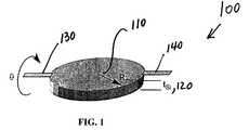
- FIG. 1shows a circular conductive plate on torsional springs in accordance with a preferred embodiment of the present invention.
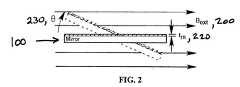
- FIG. 2shows the mirror of FIG. 1 rotating in a magnetic field.
- FIG. 3shows a top view of the mirror of FIG. 1 in a time varying magnetic field.
- FIG. 4shows a plot of Q versus Cu layer thickness varying from 600 ⁇ to 3 ⁇ m.
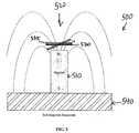
- FIG. 5shows a conductive plate rotating in a high magnetic field gradient induced by a permanent magnet in accordance with a preferred embodiment of the present invention.
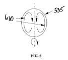
- FIG. 6shows eddy currents induced by rotation of the conductive plate of FIG. 5 in the field gradient region.
- FIG. 7shows a monolithic magnet with protruding nubs used with the conductive plate in FIG. 5 in accordance with a preferred embodiment of the present invention.
- FIG. 8shows a side view of additional conductive layers beneath coils in accordance with a preferred embodiment of the present invention.
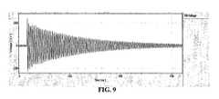
- FIG. 9shows the ringdown for a mirror with no conductive damping layer.
- FIG. 10shows the ringdown for a mirror with a conductive damping layer in accordance with the present invention.
- FIG. 11shows a double-paddle shaped mirror in accordance with another preferred embodiment of the present invention.
- FIG. 12shows the conductive path assumed on the mirror of FIG. 11 in accordance with analysis of the present invention.
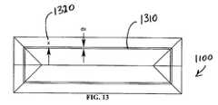
- FIG. 13shows the incremental current path of FIG. 12 in accordance with a preferred embodiment of the present invention.
- FIG. 1a circular mirror 100 is shown in accordance with a preferred embodiment of the present invention having a radius R mir 110 and a thickness t Si 120 .
- Circular mirror 100rotates around two flexures 130 and 140 , the flexures being coplanar with one surface of the mirror 100 .
- the thickness t SI 120 of the mirror 100is in the range of 1 to 1000 microns and the radius R mir 110 of the mirror 100 is in the range of 0.01 to 2.0 mm in accordance with a preferred embodiment of the present invention.
- in-plane magnetic field of strength B ext 200applied to the mirror 100 of FIG. 1 is shown.
- This type of configuration with at least one conductive plateis suitable for damping a single axis of rotation.
- In-plane magnetic field of strength B ext 200is in the range of 0.1 to 1.5 Tesla in accordance with a preferred embodiment of the present invention.
- circular mirror 100is assumed to be perfectly round having a uniform conductive layer (a metal such as copper) of thickness t m 220 on one side. Thickness t m 220 is in the range of 1 to 1000 microns in accordance with a preferred embodiment of the present invention. In accordance with another aspect of the preferred embodiment of the present invention, the majority of the conductive plate or mirror 100 is conductive.
- this conductive layer 220may be desirable for symmetry to have this conductive layer 220 on both sides of the mirror 100 to reduce thermal stress induced mirror curvature (not shown). It is also assumed that the conductive layer 220 is thin enough and the frequency ⁇ 0 of motion of the mirror 100 is low enough that the magnetic field 200 penetrates through the entire conductive layer 220 , i.e. the skin depth is much greater than thickness t m 220 .
- the changing magnetic fieldinduces currents to flow in circles in the conductive layer.
- annular region 330 between r 310 and r 310 +dr 320is considered as indicated in FIG. 3.
- Equation (9)The equation of motion for a rotational spring-mass-damper system is defined in equation (9) as follows:
- I ⁇ umlaut over ( ) ⁇⁇ ext ⁇ b ⁇ dot over ( ⁇ ) ⁇ k ⁇ ⁇ 9.
- FIG. 4a plot 400 of Q versus metal layer thickness 220 for a copper layer that varies from 600 ⁇ to 3 ⁇ m in thickness is shown in accordance with the preferred embodiment of the present invention. This plot signifies how greatly the Q is reduced by the addition of the conductive layer and the magnetic field.
- a strong magnetic field gradient at a conductive platepermits damping of two orthogonal axes of rotation.
- the eddy currents and damping of a mirror in this magnetic fieldare somewhat different from those that arise when a conductive plate rotates in a uniform magnetic field as was described supra.
- an arrangement 500that includes magnet 510 with a strong field gradient region 520 in the range of 100 to 15,000 Tesla per meter at the end and a conductive plate such as a MEMS mirror 530 of thickness in the range of 1 to 1000 microns and radius of 0.01 to 2.00 mm in the strong field gradient region 520 in accordance with a preferred embodiment of the present invention is shown.
- the conductive layer thickness 535 of mirror 530is in the range of 1 to 1000 microns in accordance with the preferred embodiment of the present invention.
- the majority of the conductive plate or mirror 530is conductive.
- a soft magnetic base plate 540Also shown is a soft magnetic base plate 540 . If the plate 530 rotates, one half of the mirror 530 moves towards the magnet 510 , resulting in an increasing magnetic flux density variation, and one half moves away from the magnet, resulting in a decrease in flux density.
- This changing fieldinduces eddy currents 610 as shown in FIG. 6.
- the flow of these eddy currents 610 induced by the changing flux densityresists motion of the mirror and results in damping.
- the analysis of damping in this caseis somewhat more complicated than that in a uniform field as will be described infra.
- Finite Element Analysis [FEA] techniquescan also be utilized to analyze the damping in this embodiment.
- the field gradient magnetsdampen both axes of rotation of the mirrors.
- This technique for 2-axis dampingcan be extended to an array of mirrors by using a magnet array that creates an array of high field gradient regions.
- R ⁇(also denoted by b previously) characterizes the rotational damping coefficient.
- the damping coefficientis calculated by FEA techniques using a particular magnet configuration 700 with protruding nubs 710 , as shown in FIG. 7.
- a magnet configuration with filled holesis also contemplated in the present invention (not shown in FIG. 7).
- a Q of 43is predicted when there is a 2 micron copper layer on the mirror with magnet configuration including nubs 810 .
- measured resultsshow a Q as low as 9 using a checkerboard magnet configuration without nubs 710 shown in FIG. 7.
- a Q as low as 2is predicted using a filled hole magnet configuration when there is a 30 micron mirror thickness, a 5 micron copper layer thickness and thinner silicon used.
- a device 800is shown in accordance with the preferred embodiment of the present invention to include fabrication by adding a 2 micron thick Cu conductive layer 810 and an extra polyimide layer 820 (to avoid shorting the coils) to a standard mirror process.
- This standard processincludes a structural silicon layer 860 , a reflective layer 870 , two Au coil layers 830 , insulating layers 820 , 840 , and 850 , and is described in further detail in pending U.S. patent application Ser. No. 09/939,422, entitled, MAGNETICALLY ACTUATED MICRO-ELECTRO-MECHANICAL APPARATUS AND METHOD OF MANUFACTURE, filed on Aug. 24, 2001, assigned to Corning IntelliSense Corporation, a wholly owned subsidiary of Assignee hereof and incorporated herein by reference.
- Qcan be measured for devices with and without the Cu conductive layer by the ring-down method where a small voltage pulse can be applied to start the mirrors ringing and a laser vibrometer can read out the mirror velocity as a function of time.
- FIG. 9the ringdown for a mirror with no conductive damping layer is shown.
- damping in this deviceis primarily due to air damping between the mirror and the magnets. Since this gap is large (on the order of 300 microns), little damping is achieved as is shown in FIG. 9 by the large number of cycles before amplitude is reduced.
- the Q of this type of mirroris 30 as depicted in TABLE 2.
- FIG. 10the ring-down for a mirror with a 2 micron Cu conductive layer added is shown in accordance with a result of the preferred embodiment of the present invention.
- the ringdown 1010is markedly shorter at 250 ms, indicating that the magnetic damping is having the desired effect.
- the Q of this type of mirroris 9 as depicted in TABLE 2.
- TABLE 2 Values utilized in calculating damping and the mechanical quality factor (Q) in accordance with a preferred embodiment of the present inventionCheckerboard Checkerboard Filled Hole Magnets Embodiment Embodiment Embodiment Ranges Cu thickness No Cu 2 ⁇ m Cu 5 ⁇ m Cu, Thinner Si 1-1000 microns Mirror 50 ⁇ m 50 ⁇ m 30 ⁇ m 1-1000 microns Thickness Mirror 0.65 mm 0.65 mm 0.65 mm 0.01-2.00 mm Radius Q 30 9 (measured) 2 (predicted) 2 (predicted) (measured)
- FIG. 11a typical mirror 1100 in accordance with another preferred embodiment of the present invention is shown.
- the magnetic field B 1110is assumed constant and parallel to the long axis and in the range of 0.1 to 2.0 Tesla or 0.1 to 1.5 Tesla/radian.
- the mirror 1100is shown as a double-ended or double-sided paddle with a mirror 1120 on one end, actuation coils 1130 on the other, and torsional hinges 1140 in the center.
- the rectangular mirror 1100has a thickness in the range of 0.001 to 1.0 mm (not shown), with a length L 1210 in the range of 0.05 to 4.0 mm (shown in FIGS.
- the conductive damping layer 1170(and coils 1130 ) are only on one side of the hinges 1140 to avoid warping the mirror 1120 side. Analysis of the layer on both sides, though possible, is not described herein.
- the conductive layer 1170 thicknessis in the range of 0.001 to 1.0 mm in accordance with the preferred embodiment of the present invention.
- the majority of the conductive plate or mirror 1100is conductive.
- FIG. 12the conductive path 1230 assumed on the mirror paddle 1200 (one side of mirror 1100 of FIG. 11) in accordance with the present invention is shown.
- FIG. 13the mirror paddle 1200 is shown having an incremental current path 1310 parameterized by the variable x 1320 in accordance with a preferred embodiment of the present invention.
- Length of Path 13102( L ⁇ W )+8 x 16.
- a columnis added to TABLE 3 below labeled “Optimized for Q” representing a design which is still further optimized for damping.
- the ratio of L/Wis kept small, the silicon thickness is minimized, the conductive layer is thickened, and a high value for B 0 is assumed. Using these values, results in a much-reduced Q value of 3.4 as shown in TABLE 3 below in the column labeled “Optimized for Q”.
- one strategyis to reduce mirror mass and moment of inertia, primarily by thinning the silicon (Si). This strategy is limited by the requirement for flat mirrors. Moment of inertia varies linearly with the mass/unit area of the mirror. A silicon mirror thickness of 30 microns is usable in accordance with a preferred embodiment of the present invention, depending on radius of curvature requirements.
- a second alternate strategy of reducing Qwould be to increase the conductive copper (Cu) layer thickness.
- the layer thicknesscan be increased to 5 microns without severely complicating the fabrication process.
- a third means for decreasing the Q factorwould be to increase the magnetic flux density variation as a function of angle or ⁇ ⁇ ⁇ ⁇
- a fourth means for increasing dampingis to use a highly conductive material such as aluminum for the structural body of the mirror rather than silicon. In this way, the conductive layer is maximized without adding additional mass for a less conductive structural layer. Alloys of aluminum known in the art may also be employed to increase the yield strength of the aluminum mirrors.
- the net result of implementing the strategies described supracan be a Q of less than 2 as depicted in last column of the table as shown in TABLE 2.
- additional active electronic damping or combined positive/negative pulse drivestrategies known in the art, settling time can be reduced further still and hence, the effective Q can be reduced still further.
- the present invention and above preferred embodimentsalso describe the use of magnetic damping for reducing ringing and easing the burden on the control electronics for rapid switching.
- several methods of introducing a conductive layer on the mirrorare known in the art and possible, such as electroplating, sputtering, evaporation, etc. on either side of the mirror.
- the preferred solution in accordance with the present inventionis to add a layer of copper, silver, gold, tungsten, or aluminum. This layer is best kept off the flexures or hinges 1140 such that hysteresis is not added to the torsional flexures. This can be easily accomplished with one additional photolithography step before or after the coil photolithography steps or by using a shadow mask.
Landscapes
- Physics & Mathematics (AREA)
- General Physics & Mathematics (AREA)
- Optics & Photonics (AREA)
- Micromachines (AREA)
Abstract

Description
- This invention relates to magnetic damping, and in particular to magnetic damping of MEMS rotational devices.[0001]
- Damping has been identified as an important principle for micromechanical devices to help reduce errors and speed settling while improving stability. Micromechanical devices can be fabricated with purely elastic supports, resulting in a classic spring-mass-damper system. In many microelectromechanical (MEMS) systems, the primary source of damping is air damping, which may be insufficient with systems with relatively large air gaps. Under-damped MEMS can lead to long settling times and make closed loop control challenging. The introduction of fluids can lead to over-damped MEMS.[0002]
- Several known damping mechanisms exist such as fluid damping and mechanical friction. Prior art solutions to perfect damping in MEMS mirrors have used soft metals, such as gold, on the springs or the supports, while other solutions have used other soft or plastic materials on the springs. However, these prior art solutions typically cause hysteresis, an undesirable result bringing about uncertainty of the MEMS angular position.[0003]
- Another prior art solution, described in “A Magnetically Damped Momentum Transfer Device to Reduce Chatter in a Micro-Mechanical Switch” 0-7803-5998-4/01 IEEE 2001, pages 265-268, a switch is described where the bounce after contact is reduced by using magnetic damping to reduce linear momentum while maintaining high contact forces. However, this prior art solution presents no viable solution for a rotating MEMS device.[0004]
- In the control of a rotational MEMS device such as a mirror, it is desirable to have a fast response time and a fast settling time. The optimal response is generally achieved by reducing the mechanical Q factor such that it is close to one (1). Many MEMS devices do not have sufficient air damping to achieve a low Q, hence there is a need for a method to introduce additional damping without adding hysteresis or fluids.[0005]
- Fluids can contaminate a MEMS device and add to the cost and complexity of packaging. Furthermore, variations in fluid properties can defocus an optical beam and cause insertion loss.[0006]
- A need exists for a method and apparatus for magnetic damping as a means of reducing the Q of MEMS rotating mirrors without introducing hysteresis, narrow gaps or fluids.[0007]
- One aspect of a preferred embodiment of the present invention relates to a device for magnetic damping including at least one conductive plate having a conductive layer, the plate capable of rotating in an applied magnetic field. In another aspect, the invention includes the conductive plate as a MEMS mirror; the conductive plate being round; the majority of said conductive plate being conductive; and the conductive plate rotating around a pair of flexures that support the plate. Another aspect of the present invention relates to a thickness of the mirror in the range of 1 to 1000 microns; a radius of said mirror in the range of 0.01 mm to 2.0 mm; the magnetic field in the range of 0.1 Tesla to 1.5 Tesla; the conductive layer thickness in the range of 1 micron to 1000 microns; and a resulting mechanical quality factor (Q) of the mirror in the range of 0.1 to 30.[0008]
- One aspect of another preferred embodiment of the present invention relates to a device for magnetic damping including a magnet producing a magnetic field and at least one conductive plate capable of rotating about two axes in the magnetic field. In another aspect, the invention includes each of the at least one conductive plates is a MEMS mirror; each of the at least one conductive plates is a round mirror; each of the at least one conductive plates has a conductive layer; and the majority of each of the at least one conductive plates being conductive. In another aspect, the invention includes a monolithic magnet with protruding nubs. In another aspect, the invention includes a monolithic magnet with filled holes. Another aspect of the invention relates to a thickness of the mirror in the range of 1 to 1000 microns; a radius of the mirror in the range of 0.01 mm to 2.00 mm; the magnetic field in the range of 0.1 to 1.5 Tesla per meter; the conductive layer thickness in the range of 1 to 1000 microns; and a mechanical quality factor (Q) of the mirror less than 2.[0009]
- One aspect of yet another preferred embodiment of the present invention relates to a device for magnetic damping including a magnet producing a magnetic field and at least one conductive plate having a conductive layer capable of rotating about a single axis in the magnetic field. In another aspect, the invention includes the at least one conductive plates is a MEMS mirror; the mirror has a rectangular shape; the mirror is a double-ended paddle mirror with actuation coils and hinges; the majority of the at least one conductive plates is conductive. Another aspect of the invention relates to the conductive layer having a thickness in the range of 0.001 mm to 1.0 mm; the conductive layer and actuation coils on one end of the double-ended paddle; a thickness of the mirror in the range of 0.001 mm to 1.0 mm; a length of the mirror in the range of 0.05 mm to 4.00 mm; a width of the mirror in the range of 0.005 mm to 1.00 mm; the magnetic field in the range of 0.1 Tesla to 1.5 Tesla; and a resulting mechanical quality factor (Q) of the mirror in the range of 0.1 to 30.[0010]
- One aspect of still yet another preferred embodiment of the present invention relates to a method for increasing magnetic damping of a MEMS rotational device including the steps of placing a conductive layer on at least one conductive plate and applying a magnetic field to the at least one conductive plate, the at least one conductive plate capable of rotation in the magnetic field.[0011]
- In another aspect, the invention relates to the conductive layer having a thickness in the range of 1 to 1000 microns; the conductive layer being made of copper; the at least one conductive plate is a MEMS mirror. In one aspect, the invention relates to a round mirror. In another aspect the mirror is rectangular. In another aspect, the invention relates to a method where a resulting mechanical quality factor (Q) is in the range of 0.1 to 30.[0012]
- Additional features and advantages of the invention will be set forth in the detailed description which follows, and in part will be readily apparent to those skilled in the art from the description or recognized by practicing the invention as described in the written description and claims hereof, as well as the appended drawings.[0013]
- It is to be understood that both the foregoing general description and the following detailed description are merely exemplary of the invention, and are intended to provide an overview or framework to understanding the nature and character of the invention as it is claimed. As will be realized, the invention is capable of other and different embodiments and its several details may be capable of modifications in various respects, all without departing from the invention.[0014]
- The accompanying drawings are included to provide a further understanding of the invention, and are incorporated in and constitute a part of this specification. The drawings illustrate one or more embodiment(s) of the invention, and together with the description serve to explain the principles and operation of the invention.[0015]
- Accordingly, the drawings and description are to be regarded as illustrative in nature and not in a restrictive or limiting sense with the scope of the application being indicated in the claims.[0016]
- This invention is further illustrated with reference to the following drawings in which:[0017]
- FIG. 1 shows a circular conductive plate on torsional springs in accordance with a preferred embodiment of the present invention.[0018]
- FIG. 2 shows the mirror of FIG. 1 rotating in a magnetic field.[0019]
- FIG. 3 shows a top view of the mirror of FIG. 1 in a time varying magnetic field.[0020]
- FIG. 4 shows a plot of Q versus Cu layer thickness varying from 600 Å to 3 μm.[0021]
- FIG. 5 shows a conductive plate rotating in a high magnetic field gradient induced by a permanent magnet in accordance with a preferred embodiment of the present invention.[0022]
- FIG. 6 shows eddy currents induced by rotation of the conductive plate of FIG. 5 in the field gradient region.[0023]
- FIG. 7 shows a monolithic magnet with protruding nubs used with the conductive plate in FIG. 5 in accordance with a preferred embodiment of the present invention.[0024]
- FIG. 8 shows a side view of additional conductive layers beneath coils in accordance with a preferred embodiment of the present invention.[0025]
- FIG. 9 shows the ringdown for a mirror with no conductive damping layer.[0026]
- FIG. 10 shows the ringdown for a mirror with a conductive damping layer in accordance with the present invention.[0027]
- FIG. 11 shows a double-paddle shaped mirror in accordance with another preferred embodiment of the present invention.[0028]
- FIG. 12 shows the conductive path assumed on the mirror of FIG. 11 in accordance with analysis of the present invention.[0029]
- FIG. 13 shows the incremental current path of FIG. 12 in accordance with a preferred embodiment of the present invention.[0030]
- Reference will now be made in detail to the present preferred embodiments of the invention, examples of which are illustrated in the accompanying drawings. Wherever possible, the same reference numbers will be used throughout the drawings to refer to the same or like parts.[0031]
- Several preferred embodiments of the present invention showing the effectiveness of magnetic damping for the plate rotating in a high magnetic field gradient will be described and analyzed infra as follows: (1) a conductive plate rotating about a single axis in a uniform magnetic field; (2) a conductive plate rotating about two axes in a high magnetic field gradient region; and (3) a conductive rectangular plate rotating in a magnetic field.[0032]
- Referring now to FIG. 1 a[0033]
circular mirror 100 is shown in accordance with a preferred embodiment of the present invention having aradius R mir110 and athickness t Si120.Circular mirror 100 rotates around twoflexures mirror 100. Thethickness t SI120 of themirror 100 is in the range of 1 to 1000 microns and theradius R mir110 of themirror 100 is in the range of 0.01 to 2.0 mm in accordance with a preferred embodiment of the present invention. - Referring now to FIG. 2 an in-plane magnetic field of[0034]
strength B ext200 applied to themirror 100 of FIG. 1 is shown. This type of configuration with at least one conductive plate is suitable for damping a single axis of rotation. In-plane magnetic field ofstrength B ext200 is in the range of 0.1 to 1.5 Tesla in accordance with a preferred embodiment of the present invention. - In accordance with the present invention and for ease of analysis,[0035]
circular mirror 100 is assumed to be perfectly round having a uniform conductive layer (a metal such as copper) ofthickness t m220 on one side.Thickness t m220 is in the range of 1 to 1000 microns in accordance with a preferred embodiment of the present invention. In accordance with another aspect of the preferred embodiment of the present invention, the majority of the conductive plate ormirror 100 is conductive. - It may be desirable for symmetry to have this[0036]
conductive layer 220 on both sides of themirror 100 to reduce thermal stress induced mirror curvature (not shown). It is also assumed that theconductive layer 220 is thin enough and the frequency ω0of motion of themirror 100 is low enough that themagnetic field 200 penetrates through the entireconductive layer 220, i.e. the skin depth is much greater thanthickness t m220. - For this type of embodiment, in determining the Q factor, the effective magnetic field penetrating the[0037]
mirror 100 shown in FIG. 1 is represented by the following equation (1) for Beff: - Beff=Bextsin (θ(t))=Bextsin (θmaxsin (ω0t))=Bextsin (θ(t)) 1.
- Assuming the mirror is rotating sinusoidally at its resonant frequency, then angle θ230 is represented by the following equation (2):[0038]
- θ=θmaxsin (ω0t) 2.
- In accordance with the analysis of the present embodiment, assuming that θ is very small allows cos(θ) to be replaced by 1. This is a reasonable assumption in accordance with the present invention since for optical switches the angles required are on the order of 10°.[0040]
- To calculate the power dissipated in a circular conductive plate with a uniform time varying magnetic field, an[0041]
annular region 330 betweenr 310 andr 310+dr 320, is considered as indicated in FIG. 3. - The equation of motion for a rotational spring-mass-damper system is defined in equation (9) as follows:[0047]
- I{umlaut over ()}=Στext−b{dot over (θ)}−kθθ 9.

- The power dissipated by the linear damping coefficient b is proportional to the rotational velocity and the damping torque as given by equation (12):[0050]
- PD={dot over (θ)}τD=b{dot over (θ)}2 12.
- Referring now to TABLE 1, sample variable values used for calculation of Q is shown in accordance with the preferred embodiment of the present invention. The resulting Q value is 1.7 as shown in TABLE 1 below. In accordance with the preferred embodiment of the present invention, the Q of the[0052]
mirror 100 described supra can be in the range of 0.1 to 30 (unitless).TABLE 1 Values utilized in calculating damping and the mechanical quality factor (Q) in accordance with the preferred embodiment of the present invention Variable Value Description Ranges ω0 2π 80 Hz Mirror resonant Design specific frequency tSi 50 μm Thickness of mirror 1-1000 microns rmir 0.65 mm Radius of mirror 0.1-2.0 mm ρm(Cu) 1.6 × 10⁻⁶Ω-cm Electrical resistivity Physical constant of Cu Bext 0.6 T External magnetic 0.1 to 1.5 Tesla field tm 3.0 μm Damping metal 1-1000 microns thickness ρ (Si) 2.3 × 10³kg/m3 Density of silicon Design specific Q 1.7 Mechanical quality 0.1 to 30 (unitless) factor - Referring to FIG. 4, a[0053]
plot 400 of Q versusmetal layer thickness 220 for a copper layer that varies from 600 Å to 3 μm in thickness is shown in accordance with the preferred embodiment of the present invention. This plot signifies how greatly the Q is reduced by the addition of the conductive layer and the magnetic field. - In an alternate preferred embodiment of the present invention, a strong magnetic field gradient at a conductive plate permits damping of two orthogonal axes of rotation. As will be described infra, the eddy currents and damping of a mirror in this magnetic field are somewhat different from those that arise when a conductive plate rotates in a uniform magnetic field as was described supra.[0054]
- Referring now to FIG. 5, an[0055]
arrangement 500 that includes magnet510 with a strongfield gradient region 520 in the range of 100 to 15,000 Tesla per meter at the end and a conductive plate such as aMEMS mirror 530 of thickness in the range of 1 to 1000 microns and radius of 0.01 to 2.00 mm in the strongfield gradient region 520 in accordance with a preferred embodiment of the present invention is shown. Theconductive layer thickness 535 ofmirror 530 is in the range of 1 to 1000 microns in accordance with the preferred embodiment of the present invention. In accordance with another aspect of the preferred embodiment of the present invention, the majority of the conductive plate ormirror 530 is conductive. - Also shown is a soft[0056]
magnetic base plate 540. If theplate 530 rotates, one half of themirror 530 moves towards the magnet510, resulting in an increasing magnetic flux density variation, and one half moves away from the magnet, resulting in a decrease in flux density. - This changing field induces[0057]
eddy currents 610 as shown in FIG. 6. The flow of theseeddy currents 610 induced by the changing flux density resists motion of the mirror and results in damping. The analysis of damping in this case is somewhat more complicated than that in a uniform field as will be described infra. Finite Element Analysis [FEA] techniques can also be utilized to analyze the damping in this embodiment. - In the present preferred embodiment, although the uniform magnetic field only permits damping in one axis of rotation, the field gradient magnets dampen both axes of rotation of the mirrors. This technique for 2-axis damping can be extended to an array of mirrors by using a magnet array that creates an array of high field gradient regions.[0058]
- Analysis of this embodiment is similar to the uniform field case described supra, except in this analysis the two halves are treated separately. The flux coupling through one half of the plate is represented by φ. The average resistance seen by the current circulating in each half of the plate is denoted by R. The voltage induced around a loop in each half is represented by the equation (14) below:[0059]

- where R[0061]θ(also denoted by b previously) characterizes the rotational damping coefficient.
- In this demonstration, the damping coefficient is calculated by FEA techniques using a[0062]
particular magnet configuration 700 with protruding nubs710, as shown in FIG. 7. Similarly, a magnet configuration with filled holes is also contemplated in the present invention (not shown in FIG. 7). These and other magnet configurations and additional elements of the configurations are described in further detail in pending U.S. patent application Ser. No. 10/180,013, assigned to Assignee hereof, entitled, APPARATUS, DEVICE AND METHOD FOR GENERATING MAGNETIC FIELD GRADIENT, filed on Jun. 25, 2002, and incorporated by reference herein. - A Q of 43 is predicted when there is a 2 micron copper layer on the mirror with magnet[0063]
configuration including nubs 810. However, measured results show a Q as low as 9 using a checkerboard magnet configuration without nubs710 shown in FIG. 7. Further, a Q as low as 2 is predicted using a filled hole magnet configuration when there is a 30 micron mirror thickness, a 5 micron copper layer thickness and thinner silicon used. Some of these results are tabulated in TABLE 2. Advanced magnet configurations with extremely high field gradients including but not limited to that shown in FIG. 7 should produce even more improved damping results. - In general, a larger uninterrupted region for current flow results in higher power dissipation, and the rotation in the region of[0064]
strong field gradient 520 divides the conductor into two effective current paths which explains why the Q is larger than the case involving a uniform field. - Referring now to FIG. 8 a device[0065]800 is shown in accordance with the preferred embodiment of the present invention to include fabrication by adding a 2 micron thick Cu
conductive layer 810 and an extra polyimide layer820 (to avoid shorting the coils) to a standard mirror process. - This standard process includes a[0066]
structural silicon layer 860, areflective layer 870, two Au coil layers830, insulatinglayers - Q can be measured for devices with and without the Cu conductive layer by the ring-down method where a small voltage pulse can be applied to start the mirrors ringing and a laser vibrometer can read out the mirror velocity as a function of time.[0067]
- Referring now to FIG. 9 the ringdown for a mirror with no conductive damping layer is shown. Hence, damping in this device is primarily due to air damping between the mirror and the magnets. Since this gap is large (on the order of 300 microns), little damping is achieved as is shown in FIG. 9 by the large number of cycles before amplitude is reduced. The Q of this type of mirror is 30 as depicted in TABLE 2.[0068]
- On the contrary, referring now to FIG. 10 the ring-down for a mirror with a 2 micron Cu conductive layer added is shown in accordance with a result of the preferred embodiment of the present invention.[0069]
- The[0070]
ringdown 1010 is markedly shorter at 250 ms, indicating that the magnetic damping is having the desired effect. The Q of this type of mirror is 9 as depicted in TABLE 2.TABLE 2 Values utilized in calculating damping and the mechanical quality factor (Q) in accordance with a preferred embodiment of the present invention Checkerboard Checkerboard Filled Hole Magnets Embodiment Embodiment Embodiment Ranges Cu thickness No Cu 2 μm Cu 5 μm Cu, Thinner Si 1-1000 microns Mirror 50 μm 50 μm 30 μm 1-1000 microns Thickness Mirror 0.65 mm 0.65 mm 0.65 mm 0.01-2.00 mm Radius Q 30 9 (measured) 2 (predicted) 2 (predicted) (measured) - It should be noted that while the data shown in FIG. 10 are specific to the preferred embodiment involving a plate rotating about two axes in a high magnetic field gradient in accordance with the present invention as discussed supra, the ring-down of a device with a conductive layer would generally extend to and have similar desired effects for a preferred embodiment of the present invention involving a plate rotating about a single axis in a uniform magnetic field as discussed supra or a rectangular plate rotating in a magnetic field as will be discussed infra.[0071]
- Many devices, such as photonic switching mirror arrays, require an array of rectangular mirrors rotating about a single axis. Magnetic damping can be used to add linear non-contact, non-hysteretic damping to such configurations.[0072]
- Referring now to FIG. 11 a[0073]
typical mirror 1100 in accordance with another preferred embodiment of the present invention is shown. Themagnetic field B 1110 is assumed constant and parallel to the long axis and in the range of 0.1 to 2.0 Tesla or 0.1 to 1.5 Tesla/radian. Themirror 1100 is shown as a double-ended or double-sided paddle with amirror 1120 on one end, actuation coils1130 on the other, and torsional hinges1140 in the center. Therectangular mirror 1100 has a thickness in the range of 0.001 to 1.0 mm (not shown), with alength L 1210 in the range of 0.05 to 4.0 mm (shown in FIGS. 11 and 12), a width W1220 in the range of 0.005 to 1.000 mm (shown in FIGS. 11 and 12), and a gap L11160 in the range of 0.050 to 2.0 mm in accordance with the preferred embodiment of the present invention. These and other variable values are tabulated in TABLE 3 below in accordance with the preferred embodiment of the present invention. - For the analysis of this preferred embodiment in accordance with the present invention it shall be assumed that the conductive damping layer[0074]1170 (and coils1130) are only on one side of the
hinges 1140 to avoid warping themirror 1120 side. Analysis of the layer on both sides, though possible, is not described herein. Theconductive layer 1170 thickness is in the range of 0.001 to 1.0 mm in accordance with the preferred embodiment of the present invention. In accordance with another aspect of the preferred embodiment of the present invention, the majority of the conductive plate ormirror 1100 is conductive. - Referring now to FIG. 12 the[0075]
conductive path 1230 assumed on the mirror paddle1200 (one side ofmirror 1100 of FIG. 11) in accordance with the present invention is shown. Referring to FIG. 13 themirror paddle 1200 is shown having an incrementalcurrent path 1310 parameterized by the variable x1320 in accordance with a preferred embodiment of the present invention. - While generally not so in nature, it is assumed for ease of illustration that the[0076]
current paths rectangular mirror 1100. The actual current paths will likely be more elliptical, since the current will generally take the path of least resistance. Hence, the actual damping will be somewhat larger than that manifested infra. - The length of an incremental[0077]
current path 1310 is described by the following equation (16) where x1320 is the distance from the center line to thepath 1310 as shown in FIG. 13: - Length of
Path 1310=2(L−W)+8x 16. - where the thicknesses and densities of silicon, copper and gold are indicated by t and ρ, and where L[0084]11160 is the gap in the middle of the paddle where the flexure attaches as shown referring back to FIG. 11. It should be noted that the damping layer and coils are assumed to be only on one end of the paddle to reduce mirror curvature.
- Sample data and calculations for the[0086]
mirror 1100 in accordance with the present invention are shown in TABLE 3 using the above formulas. Note, as mentioned supra, that the formula underestimates damping due to the assumption of rectangular current flow. The mechanical Q factor of this preferred embodiment of the present invention is in the range of 0.1 to 30 (unitless). As shown below in TABLE 3, the value for Q is 24 for the design as described above. - In accordance with another aspect of the preferred embodiment of the present invention, a column is added to TABLE 3 below labeled “Optimized for Q” representing a design which is still further optimized for damping. To optimize damping in this scenario, the ratio of L/W is kept small, the silicon thickness is minimized, the conductive layer is thickened, and a high value for B[0087]0is assumed. Using these values, results in a much-reduced Q value of 3.4 as shown in TABLE 3 below in the column labeled “Optimized for Q”.
TABLE 3 Values utilized in calculating damping and the mechanical quality factor (Q) in accordance with a preferred embodiment of the present invention Preferred Preferred Embodiment Variables Units Embodiment Optimized for Q Ranges f0 Hz 80 80 10 Hz-10 kHz 1310, Bθ T/radian 1 1.5 0.1-5 1370, tCu mm 0.005 0.006 0.001-1.0 tSi mm 0.03 0.01 0.001-1.0 1360, L1 mm 0.24 0.05 0.050-2.0 1410, L mm 0.94 0.7 0.050-4.0 1420, W mm 0.5 0.4 0.005-1.0 Q None 24 3.4 0.1-30 - In accordance with the above-described preferred embodiments of the present invention, there are several strategies for further increasing the magnetic damping and desirably decreasing the Q value. In accordance with the present invention one strategy is to reduce mirror mass and moment of inertia, primarily by thinning the silicon (Si). This strategy is limited by the requirement for flat mirrors. Moment of inertia varies linearly with the mass/unit area of the mirror. A silicon mirror thickness of 30 microns is usable in accordance with a preferred embodiment of the present invention, depending on radius of curvature requirements.[0088]
- A second alternate strategy of reducing Q would be to increase the conductive copper (Cu) layer thickness. The layer thickness can be increased to 5 microns without severely complicating the fabrication process.[0089]
- have been fabricated. This can result in a 2.25 times reduction in the Q value.[0092]
- A fourth means for increasing damping is to use a highly conductive material such as aluminum for the structural body of the mirror rather than silicon. In this way, the conductive layer is maximized without adding additional mass for a less conductive structural layer. Alloys of aluminum known in the art may also be employed to increase the yield strength of the aluminum mirrors.[0093]
- In accordance with a preferred embodiment of the present invention, the net result of implementing the strategies described supra can be a Q of less than 2 as depicted in last column of the table as shown in TABLE 2. With additional active electronic damping or combined positive/negative pulse drive, strategies known in the art, settling time can be reduced further still and hence, the effective Q can be reduced still further.[0094]
- The present invention and above preferred embodiments also describe the use of magnetic damping for reducing ringing and easing the burden on the control electronics for rapid switching. It should be noted that several methods of introducing a conductive layer on the mirror are known in the art and possible, such as electroplating, sputtering, evaporation, etc. on either side of the mirror. The preferred solution in accordance with the present invention is to add a layer of copper, silver, gold, tungsten, or aluminum. This layer is best kept off the flexures or hinges[0095]1140 such that hysteresis is not added to the torsional flexures. This can be easily accomplished with one additional photolithography step before or after the coil photolithography steps or by using a shadow mask.
- Having described various preferred embodiments of the present invention, it will be apparent to those skilled in the art that various modifications and variations can be made to the present invention without departing from the spirit and scope of the invention. Thus, it is intended that the present invention covers the modifications and variations of this invention provided they come within the scope of the appended claims and their equivalents.[0096]


Claims (44)
Priority Applications (1)
| Application Number | Priority Date | Filing Date | Title |
|---|---|---|---|
| US10/254,360US7038829B2 (en) | 2002-09-25 | 2002-09-25 | Magnetic damping for MEMS rotational devices |
Applications Claiming Priority (1)
| Application Number | Priority Date | Filing Date | Title |
|---|---|---|---|
| US10/254,360US7038829B2 (en) | 2002-09-25 | 2002-09-25 | Magnetic damping for MEMS rotational devices |
Publications (2)
| Publication Number | Publication Date |
|---|---|
| US20040057103A1true US20040057103A1 (en) | 2004-03-25 |
| US7038829B2 US7038829B2 (en) | 2006-05-02 |
Family
ID=31993348
Family Applications (1)
| Application Number | Title | Priority Date | Filing Date |
|---|---|---|---|
| US10/254,360Expired - LifetimeUS7038829B2 (en) | 2002-09-25 | 2002-09-25 | Magnetic damping for MEMS rotational devices |
Country Status (1)
| Country | Link |
|---|---|
| US (1) | US7038829B2 (en) |
Cited By (23)
| Publication number | Priority date | Publication date | Assignee | Title |
|---|---|---|---|---|
| FR2893933A1 (en)* | 2005-11-30 | 2007-06-01 | Commissariat Energie Atomique | Micro electro mechanical system type structure e.g. micro-accelerometer, dampening device, has permanent magnet creating magnetic field whose component is normal to plane of mobile or deformable plate and varied in displacement direction |
| US20080073163A1 (en)* | 2006-09-22 | 2008-03-27 | Weir Michael P | Micro-electromechanical device |
| US20080106777A1 (en)* | 2006-11-03 | 2008-05-08 | Weir Michael P | Resonant fourier scanning |
| US20080146898A1 (en)* | 2006-12-19 | 2008-06-19 | Ethicon Endo-Surgery, Inc. | Spectral windows for surgical treatment through intervening fluids |
| US20080154248A1 (en)* | 2006-12-22 | 2008-06-26 | Ethicon Endo-Surgery, Inc. | Apparatus and method for medically treating a tattoo |
| US20080151343A1 (en)* | 2006-12-22 | 2008-06-26 | Ethicon Endo-Surgery, Inc. | Apparatus including a scanned beam imager having an optical dome |
| US20080167546A1 (en)* | 2007-01-09 | 2008-07-10 | Ethicon Endo-Surgery, Inc. | Methods for imaging the anatomy with an anatomically secured scanner assembly |
| US20080173803A1 (en)* | 2007-01-18 | 2008-07-24 | Ethicon Endo-Surgery, Inc. | Scanning beam imaging with adjustable detector sensitivity or gain |
| US20080226029A1 (en)* | 2007-03-12 | 2008-09-18 | Weir Michael P | Medical device including scanned beam unit for imaging and therapy |
| US20090002794A1 (en)* | 2007-06-29 | 2009-01-01 | Ethicon Endo-Surgery, Inc. | Receiver aperture broadening for scanned beam imaging |
| US20090015695A1 (en)* | 2007-07-13 | 2009-01-15 | Ethicon Endo-Surgery, Inc. | Sbi motion artifact removal apparatus and method |
| US20090021818A1 (en)* | 2007-07-20 | 2009-01-22 | Ethicon Endo-Surgery, Inc. | Medical scanning assembly with variable image capture and display |
| US20090036734A1 (en)* | 2007-07-31 | 2009-02-05 | Ethicon Endo-Surgery, Inc. | Devices and methods for introducing a scanning beam unit into the anatomy |
| US20090245599A1 (en)* | 2008-03-27 | 2009-10-01 | Ethicon Endo-Surgery, Inc. | Method for creating a pixel image from sampled data of a scanned beam imager |
| US20090270724A1 (en)* | 2008-04-25 | 2009-10-29 | Ethicon Endo-Surgery, Inc. | Scanned beam device and method using same which measures the reflectance of patient tissue |
| US7925333B2 (en) | 2007-08-28 | 2011-04-12 | Ethicon Endo-Surgery, Inc. | Medical device including scanned beam unit with operational control features |
| US7983739B2 (en) | 2007-08-27 | 2011-07-19 | Ethicon Endo-Surgery, Inc. | Position tracking and control for a scanning assembly |
| US7995045B2 (en) | 2007-04-13 | 2011-08-09 | Ethicon Endo-Surgery, Inc. | Combined SBI and conventional image processor |
| US8160678B2 (en) | 2007-06-18 | 2012-04-17 | Ethicon Endo-Surgery, Inc. | Methods and devices for repairing damaged or diseased tissue using a scanning beam assembly |
| US8216214B2 (en) | 2007-03-12 | 2012-07-10 | Ethicon Endo-Surgery, Inc. | Power modulation of a scanning beam for imaging, therapy, and/or diagnosis |
| US8626271B2 (en) | 2007-04-13 | 2014-01-07 | Ethicon Endo-Surgery, Inc. | System and method using fluorescence to examine within a patient's anatomy |
| US8801606B2 (en) | 2007-01-09 | 2014-08-12 | Ethicon Endo-Surgery, Inc. | Method of in vivo monitoring using an imaging system including scanned beam imaging unit |
| WO2019029552A1 (en)* | 2017-08-09 | 2019-02-14 | Huawei Technologies Co., Ltd. | Electromagnetic activated mirror array with fluid damping and micro-fabricated recess for magnet assembly |
Families Citing this family (3)
| Publication number | Priority date | Publication date | Assignee | Title |
|---|---|---|---|---|
| US8307710B2 (en)* | 2009-07-09 | 2012-11-13 | Honeywell International Inc. | Translational mass in-plane MEMS accelerometer |
| US8896074B2 (en) | 2012-01-26 | 2014-11-25 | The Charles Stark Draper Laboratory, Inc. | MEMS vibration isolation system and method |
| FR3005045A1 (en) | 2013-04-25 | 2014-10-31 | Commissariat Energie Atomique | MICROELECTROMECHANICAL AND / OR NANOELECTROMECHANICAL STRUCTURE WITH ADJUSTABLE QUALITY FACTOR |
Citations (10)
| Publication number | Priority date | Publication date | Assignee | Title |
|---|---|---|---|---|
| US4585282A (en)* | 1983-07-19 | 1986-04-29 | Bosley Robert W | Magnetic levitation system |
| US4629317A (en)* | 1981-08-21 | 1986-12-16 | Hunter Engineering Company | Vehicle wheel alignment apparatus |
| US5434462A (en)* | 1991-02-13 | 1995-07-18 | The United States Of America As Represented By The Secretary Of The Army | High-power electrical machinery |
| US5736798A (en)* | 1995-10-19 | 1998-04-07 | Eastman Kodak Company | Passive magnetic damper |
| US5892159A (en)* | 1997-10-17 | 1999-04-06 | Smith; James Everett | Mass flow rate meter |
| US5995688A (en)* | 1998-06-01 | 1999-11-30 | Lucent Technologies, Inc. | Micro-opto-electromechanical devices and method therefor |
| US20020106314A1 (en)* | 2000-03-16 | 2002-08-08 | Pelrine Ronald E. | Microlaboratory devices and methods |
| US6480645B1 (en)* | 2001-01-30 | 2002-11-12 | Tellium, Inc. | Sidewall electrodes for electrostatic actuation and capacitive sensing |
| US20030234711A1 (en)* | 2002-06-25 | 2003-12-25 | Bernstein Jonathan Jay | Apparatus, device and method for generating magnetic field gradient |
| US6831461B2 (en)* | 2001-07-23 | 2004-12-14 | Siemens Aktiengesellschaft | Magnetic resonance tomography apparatus having damping laminated sheets for reducing vibrations |
- 2002
- 2002-09-25USUS10/254,360patent/US7038829B2/ennot_activeExpired - Lifetime
Patent Citations (10)
| Publication number | Priority date | Publication date | Assignee | Title |
|---|---|---|---|---|
| US4629317A (en)* | 1981-08-21 | 1986-12-16 | Hunter Engineering Company | Vehicle wheel alignment apparatus |
| US4585282A (en)* | 1983-07-19 | 1986-04-29 | Bosley Robert W | Magnetic levitation system |
| US5434462A (en)* | 1991-02-13 | 1995-07-18 | The United States Of America As Represented By The Secretary Of The Army | High-power electrical machinery |
| US5736798A (en)* | 1995-10-19 | 1998-04-07 | Eastman Kodak Company | Passive magnetic damper |
| US5892159A (en)* | 1997-10-17 | 1999-04-06 | Smith; James Everett | Mass flow rate meter |
| US5995688A (en)* | 1998-06-01 | 1999-11-30 | Lucent Technologies, Inc. | Micro-opto-electromechanical devices and method therefor |
| US20020106314A1 (en)* | 2000-03-16 | 2002-08-08 | Pelrine Ronald E. | Microlaboratory devices and methods |
| US6480645B1 (en)* | 2001-01-30 | 2002-11-12 | Tellium, Inc. | Sidewall electrodes for electrostatic actuation and capacitive sensing |
| US6831461B2 (en)* | 2001-07-23 | 2004-12-14 | Siemens Aktiengesellschaft | Magnetic resonance tomography apparatus having damping laminated sheets for reducing vibrations |
| US20030234711A1 (en)* | 2002-06-25 | 2003-12-25 | Bernstein Jonathan Jay | Apparatus, device and method for generating magnetic field gradient |
Cited By (33)
| Publication number | Priority date | Publication date | Assignee | Title |
|---|---|---|---|---|
| FR2893933A1 (en)* | 2005-11-30 | 2007-06-01 | Commissariat Energie Atomique | Micro electro mechanical system type structure e.g. micro-accelerometer, dampening device, has permanent magnet creating magnetic field whose component is normal to plane of mobile or deformable plate and varied in displacement direction |
| US20080073163A1 (en)* | 2006-09-22 | 2008-03-27 | Weir Michael P | Micro-electromechanical device |
| US9079762B2 (en) | 2006-09-22 | 2015-07-14 | Ethicon Endo-Surgery, Inc. | Micro-electromechanical device |
| US20080106777A1 (en)* | 2006-11-03 | 2008-05-08 | Weir Michael P | Resonant fourier scanning |
| US7561317B2 (en) | 2006-11-03 | 2009-07-14 | Ethicon Endo-Surgery, Inc. | Resonant Fourier scanning |
| US20080146898A1 (en)* | 2006-12-19 | 2008-06-19 | Ethicon Endo-Surgery, Inc. | Spectral windows for surgical treatment through intervening fluids |
| US20080154248A1 (en)* | 2006-12-22 | 2008-06-26 | Ethicon Endo-Surgery, Inc. | Apparatus and method for medically treating a tattoo |
| US20080151343A1 (en)* | 2006-12-22 | 2008-06-26 | Ethicon Endo-Surgery, Inc. | Apparatus including a scanned beam imager having an optical dome |
| US7713265B2 (en) | 2006-12-22 | 2010-05-11 | Ethicon Endo-Surgery, Inc. | Apparatus and method for medically treating a tattoo |
| US20080167546A1 (en)* | 2007-01-09 | 2008-07-10 | Ethicon Endo-Surgery, Inc. | Methods for imaging the anatomy with an anatomically secured scanner assembly |
| US8273015B2 (en) | 2007-01-09 | 2012-09-25 | Ethicon Endo-Surgery, Inc. | Methods for imaging the anatomy with an anatomically secured scanner assembly |
| US8801606B2 (en) | 2007-01-09 | 2014-08-12 | Ethicon Endo-Surgery, Inc. | Method of in vivo monitoring using an imaging system including scanned beam imaging unit |
| US20080173803A1 (en)* | 2007-01-18 | 2008-07-24 | Ethicon Endo-Surgery, Inc. | Scanning beam imaging with adjustable detector sensitivity or gain |
| US7589316B2 (en) | 2007-01-18 | 2009-09-15 | Ethicon Endo-Surgery, Inc. | Scanning beam imaging with adjustable detector sensitivity or gain |
| US8216214B2 (en) | 2007-03-12 | 2012-07-10 | Ethicon Endo-Surgery, Inc. | Power modulation of a scanning beam for imaging, therapy, and/or diagnosis |
| US20080226029A1 (en)* | 2007-03-12 | 2008-09-18 | Weir Michael P | Medical device including scanned beam unit for imaging and therapy |
| US7995045B2 (en) | 2007-04-13 | 2011-08-09 | Ethicon Endo-Surgery, Inc. | Combined SBI and conventional image processor |
| US8626271B2 (en) | 2007-04-13 | 2014-01-07 | Ethicon Endo-Surgery, Inc. | System and method using fluorescence to examine within a patient's anatomy |
| US8160678B2 (en) | 2007-06-18 | 2012-04-17 | Ethicon Endo-Surgery, Inc. | Methods and devices for repairing damaged or diseased tissue using a scanning beam assembly |
| US20090002794A1 (en)* | 2007-06-29 | 2009-01-01 | Ethicon Endo-Surgery, Inc. | Receiver aperture broadening for scanned beam imaging |
| US20090015695A1 (en)* | 2007-07-13 | 2009-01-15 | Ethicon Endo-Surgery, Inc. | Sbi motion artifact removal apparatus and method |
| US7982776B2 (en) | 2007-07-13 | 2011-07-19 | Ethicon Endo-Surgery, Inc. | SBI motion artifact removal apparatus and method |
| US20090021818A1 (en)* | 2007-07-20 | 2009-01-22 | Ethicon Endo-Surgery, Inc. | Medical scanning assembly with variable image capture and display |
| US20090036734A1 (en)* | 2007-07-31 | 2009-02-05 | Ethicon Endo-Surgery, Inc. | Devices and methods for introducing a scanning beam unit into the anatomy |
| US9125552B2 (en) | 2007-07-31 | 2015-09-08 | Ethicon Endo-Surgery, Inc. | Optical scanning module and means for attaching the module to medical instruments for introducing the module into the anatomy |
| US7983739B2 (en) | 2007-08-27 | 2011-07-19 | Ethicon Endo-Surgery, Inc. | Position tracking and control for a scanning assembly |
| US7925333B2 (en) | 2007-08-28 | 2011-04-12 | Ethicon Endo-Surgery, Inc. | Medical device including scanned beam unit with operational control features |
| US8050520B2 (en) | 2008-03-27 | 2011-11-01 | Ethicon Endo-Surgery, Inc. | Method for creating a pixel image from sampled data of a scanned beam imager |
| US20090245599A1 (en)* | 2008-03-27 | 2009-10-01 | Ethicon Endo-Surgery, Inc. | Method for creating a pixel image from sampled data of a scanned beam imager |
| US8332014B2 (en) | 2008-04-25 | 2012-12-11 | Ethicon Endo-Surgery, Inc. | Scanned beam device and method using same which measures the reflectance of patient tissue |
| US20090270724A1 (en)* | 2008-04-25 | 2009-10-29 | Ethicon Endo-Surgery, Inc. | Scanned beam device and method using same which measures the reflectance of patient tissue |
| WO2019029552A1 (en)* | 2017-08-09 | 2019-02-14 | Huawei Technologies Co., Ltd. | Electromagnetic activated mirror array with fluid damping and micro-fabricated recess for magnet assembly |
| US10775608B2 (en) | 2017-08-09 | 2020-09-15 | Futurewei Technologies, Inc. | Electromagnetic activated mirror array with fluid damping and micro-fabricated recess for magnet assembly |
Also Published As
| Publication number | Publication date |
|---|---|
| US7038829B2 (en) | 2006-05-02 |
Similar Documents
| Publication | Publication Date | Title |
|---|---|---|
| US7038829B2 (en) | Magnetic damping for MEMS rotational devices | |
| US7498681B1 (en) | Mechanical vibration to electrical energy converter | |
| JP2657769B2 (en) | Planar type galvanometer mirror having displacement detection function and method of manufacturing the same | |
| EP0763881B1 (en) | Magnetic micro-mover | |
| US5606447A (en) | Planar type mirror galvanometer and method of manufacture | |
| Asada et al. | Silicon micromachined two-dimensional galvano optical scanner | |
| US20100187835A1 (en) | Electromagnetic Energy Scavenger Based on Moving Permanent Magnets | |
| US5724015A (en) | Bulk micromachined inductive transducers on silicon | |
| US6538799B2 (en) | Magnetically actuated torsional micro-mechanical mirror system | |
| US20050018322A1 (en) | Magnetically actuated fast MEMS mirrors and microscanners | |
| US20100296146A1 (en) | Mems scanning micromirror | |
| TW200302350A (en) | Micro-machined accelerometer | |
| Ferreira et al. | A silicon micromechanical galvanometric scanner | |
| JPH04211217A (en) | light deflector | |
| WO2007047267A2 (en) | A microelectromechanical magnetometer | |
| Judy | Batch-fabricated ferromagnetic microactuators with silicon flexures | |
| Wagner et al. | Electromagnetic microactuators with multiple degrees of freedom | |
| Isikman et al. | Dynamic modeling of soft magnetic film actuated scanners | |
| US7051591B2 (en) | Micromachined double tuning-fork gyrometer with detection in the plane of the machined wafer | |
| Yang et al. | A novel coilless scanning mirror using eddy current Lorentz force and magnetostatic force | |
| US20070064292A1 (en) | Magnet on frame oscillating device | |
| Cugat et al. | Deformable magnetic mirror for adaptive optics: first results | |
| JP7622971B2 (en) | Servo type vibration detector and vibration control device | |
| Kern et al. | Actuator design | |
| KR20180110400A (en) | A micro scanner, and fabrication method for the micro scanner |
Legal Events
| Date | Code | Title | Description |
|---|---|---|---|
| AS | Assignment | Owner name:CORNING INCORPORATED, NEW YORK Free format text:ASSIGNMENT OF ASSIGNORS INTEREST;ASSIGNOR:BERNSTEIN, JONATHAN JAY;REEL/FRAME:013345/0424 Effective date:20020920 | |
| STCF | Information on status: patent grant | Free format text:PATENTED CASE | |
| AS | Assignment | Owner name:JDS UNIPHASE CORPORATION, CALIFORNIA Free format text:ASSIGNMENT OF ASSIGNORS INTEREST;ASSIGNOR:CORNING INCORPORATED;REEL/FRAME:017766/0571 Effective date:20060523 | |
| FPAY | Fee payment | Year of fee payment:4 | |
| FPAY | Fee payment | Year of fee payment:8 | |
| AS | Assignment | Owner name:LUMENTUM OPERATIONS LLC, CALIFORNIA Free format text:ASSIGNMENT OF ASSIGNORS INTEREST;ASSIGNOR:JDS UNIPHASE CORPORATION;REEL/FRAME:036420/0340 Effective date:20150731 | |
| FEPP | Fee payment procedure | Free format text:PAYOR NUMBER ASSIGNED (ORIGINAL EVENT CODE: ASPN); ENTITY STATUS OF PATENT OWNER: LARGE ENTITY | |
| AS | Assignment | Owner name:LUMENTUM OPERATIONS LLC, CALIFORNIA Free format text:CORRECTIVE ASSIGNMENT TO CORRECT THE PATENTS LISTED ON PAGE A-A33 PREVIOUSLY RECORDED ON REEL 036420 FRAME 0340. ASSIGNOR(S) HEREBY CONFIRMS THE PATENT NUMBERS 7,868,247 AND 6,476,312 WERE LISTED IN ERROR AND SHOULD BE REMOVED;ASSIGNOR:JDS UNIPHASE CORPORATION;REEL/FRAME:037562/0513 Effective date:20150731 Owner name:LUMENTUM OPERATIONS LLC, CALIFORNIA Free format text:CORRECTIVE ASSIGNMENT TO CORRECT INCORRECT PATENTS 7,868,247 AND 6,476,312 ON PAGE A-A33 PREVIOUSLY RECORDED ON REEL 036420 FRAME 0340. ASSIGNOR(S) HEREBY CONFIRMS THE ASSIGNMENT;ASSIGNOR:JDS UNIPHASE CORPORATION;REEL/FRAME:037562/0513 Effective date:20150731 | |
| AS | Assignment | Owner name:LUMENTUM OPERATIONS LLC, CALIFORNIA Free format text:CORRECTIVE ASSIGNMENT TO CORRECT THE PATENTS LISTED ON PAGE A-A33 PATENT NUMBERS 7,868,247 AND 6,476,312 WERE LISTED IN ERROR AND SHOULD BE REMOVED. PREVIOUSLY RECORDED ON REEL 036420 FRAME 0340. ASSIGNOR(S) HEREBY CONFIRMS THE ASSIGNMENT;ASSIGNOR:JDS UNIPHASE CORPORATION;REEL/FRAME:037627/0641 Effective date:20150731 Owner name:LUMENTUM OPERATIONS LLC, CALIFORNIA Free format text:CORRECTIVE ASSIGNMENT TO CORRECT PATENTS 7,868,247 AND 6,476,312 LISTED ON PAGE A-A33 PREVIOUSLY RECORDED ON REEL 036420 FRAME 0340. ASSIGNOR(S) HEREBY CONFIRMS THE ASSIGNMENT;ASSIGNOR:JDS UNIPHASE CORPORATION;REEL/FRAME:037627/0641 Effective date:20150731 | |
| FEPP | Fee payment procedure | Free format text:PAYOR NUMBER ASSIGNED (ORIGINAL EVENT CODE: ASPN); ENTITY STATUS OF PATENT OWNER: LARGE ENTITY Free format text:PAYER NUMBER DE-ASSIGNED (ORIGINAL EVENT CODE: RMPN); ENTITY STATUS OF PATENT OWNER: LARGE ENTITY | |
| MAFP | Maintenance fee payment | Free format text:PAYMENT OF MAINTENANCE FEE, 12TH YEAR, LARGE ENTITY (ORIGINAL EVENT CODE: M1553) Year of fee payment:12 | |
| AS | Assignment | Owner name:DEUTSCHE BANK AG NEW YORK BRANCH, AS COLLATERAL AGENT, NEW YORK Free format text:PATENT SECURITY AGREEMENT;ASSIGNORS:LUMENTUM OPERATIONS LLC;OCLARO FIBER OPTICS, INC.;OCLARO, INC.;REEL/FRAME:047788/0511 Effective date:20181210 Owner name:DEUTSCHE BANK AG NEW YORK BRANCH, AS COLLATERAL AG Free format text:PATENT SECURITY AGREEMENT;ASSIGNORS:LUMENTUM OPERATIONS LLC;OCLARO FIBER OPTICS, INC.;OCLARO, INC.;REEL/FRAME:047788/0511 Effective date:20181210 | |
| AS | Assignment | Owner name:OCLARO FIBER OPTICS, INC., CALIFORNIA Free format text:RELEASE BY SECURED PARTY;ASSIGNOR:DEUTSCHE AG NEW YORK BRANCH;REEL/FRAME:051287/0556 Effective date:20191212 Owner name:OCLARO, INC., CALIFORNIA Free format text:RELEASE BY SECURED PARTY;ASSIGNOR:DEUTSCHE AG NEW YORK BRANCH;REEL/FRAME:051287/0556 Effective date:20191212 Owner name:LUMENTUM OPERATIONS LLC, CALIFORNIA Free format text:RELEASE BY SECURED PARTY;ASSIGNOR:DEUTSCHE AG NEW YORK BRANCH;REEL/FRAME:051287/0556 Effective date:20191212 |