US20030231432A1 - Windage, shock and low mass conventional suspension design - Google Patents
Windage, shock and low mass conventional suspension designDownload PDFInfo
- Publication number
- US20030231432A1 US20030231432A1US10/428,555US42855503AUS2003231432A1US 20030231432 A1US20030231432 A1US 20030231432A1US 42855503 AUS42855503 AUS 42855503AUS 2003231432 A1US2003231432 A1US 2003231432A1
- Authority
- US
- United States
- Prior art keywords
- load beam
- base plate
- width
- interconnect
- secured
- Prior art date
- Legal status (The legal status is an assumption and is not a legal conclusion. Google has not performed a legal analysis and makes no representation as to the accuracy of the status listed.)
- Abandoned
Links
Images


Classifications
- G—PHYSICS
- G11—INFORMATION STORAGE
- G11B—INFORMATION STORAGE BASED ON RELATIVE MOVEMENT BETWEEN RECORD CARRIER AND TRANSDUCER
- G11B5/00—Recording by magnetisation or demagnetisation of a record carrier; Reproducing by magnetic means; Record carriers therefor
- G11B5/48—Disposition or mounting of heads or head supports relative to record carriers ; arrangements of heads, e.g. for scanning the record carrier to increase the relative speed
- G11B5/4806—Disposition or mounting of heads or head supports relative to record carriers ; arrangements of heads, e.g. for scanning the record carrier to increase the relative speed specially adapted for disk drive assemblies, e.g. assembly prior to operation, hard or flexible disk drives
- G11B5/486—Disposition or mounting of heads or head supports relative to record carriers ; arrangements of heads, e.g. for scanning the record carrier to increase the relative speed specially adapted for disk drive assemblies, e.g. assembly prior to operation, hard or flexible disk drives with provision for mounting or arranging electrical conducting means or circuits on or along the arm assembly
- G—PHYSICS
- G11—INFORMATION STORAGE
- G11B—INFORMATION STORAGE BASED ON RELATIVE MOVEMENT BETWEEN RECORD CARRIER AND TRANSDUCER
- G11B5/00—Recording by magnetisation or demagnetisation of a record carrier; Reproducing by magnetic means; Record carriers therefor
- G11B5/48—Disposition or mounting of heads or head supports relative to record carriers ; arrangements of heads, e.g. for scanning the record carrier to increase the relative speed
- G11B5/4806—Disposition or mounting of heads or head supports relative to record carriers ; arrangements of heads, e.g. for scanning the record carrier to increase the relative speed specially adapted for disk drive assemblies, e.g. assembly prior to operation, hard or flexible disk drives
- G11B5/4826—Mounting, aligning or attachment of the transducer head relative to the arm assembly, e.g. slider holding members, gimbals, adhesive
Definitions
- the present inventionrelates to data storage devices.
- the present inventionrelates to improving performance of suspension assemblies in data storage devices.
- datais typically stored in tracks on a memory medium.
- the headis positioned within a track of the memory medium while the medium moves beneath the head.
- the headis positioned by an actuator assembly that includes a motor that rotates one or more actuator arms.
- Each actuator armsupports one or two suspensions that each support a head/gimbal assembly.
- a suspensionincludes three distinct areas: a base plate area that connects to the actuator arm, a spring area that provides a vertical spring force to bias the head toward the medium, and a load beam that extends from the spring area to the head/gimbal assembly.
- a spring force provided by the suspensionis designed to allow the head to follow height variations on the surface of the medium without impacting the medium or moving too far away from the medium.
- the spring areabe more elastic or flexible than the remainder of the suspension. However, if the spring area or the remainder of the load beam is too elastic and compliant the load beam will tend to bend and resonate in response to windage induced forces.
- Windage induced forceshave become a particular concern as the performance of disc drives has increased. For example, many high performance drives run at 15 k RPM or higher, causing significant windage forces within the disc drive. Also, there is an increasingly higher number of bits being packed into every square inch of the disc drive surface, leading to a higher number of tracks per inch and a reduced track width. As a result, suspensions are more susceptible to slider off-track motion and other mechanical resonant vibrations that lead to reduced servo bandwidth and reduced track following capabilities of the disc drive.
- the suspension designmay be altered in such a way so as to achieve higher resonance frequencies without compromising on the performance requirements of the disc drive.
- An effective way to reduce slider off-track motion resulting from windage excitationis to increase the suspension resonant frequencies.
- Suspension resonance frequenciescan be increased by, for example, reducing the length of the suspension, using a thicker sheet of material for the load beam and bend section, or reducing the effective bend length of the suspension.
- Windage driven slider off-track motionmay also result from the excitation of the electrical interconnect tail adjacent to the base plate area of the suspension.
- the tailis usually attached to suspension tabs that extend from the base plate or load beam.
- attaching the interconnect tail to suspension tabsdoes not completely eliminate the problem as the suspension tabs are typically compliant and asymmetrical, and can translate the windage driven tail motion into slider off-track motion.
- the problem of windage induced motionhas become a more significant problem as the windage forces increase with increased rotation speeds of the storage medium.
- a data storage deviceincludes a head and a suspension assembly capable of supporting the head.
- the suspension assemblyincludes a base plate having a first base plate surface facing toward the storage medium, and a load beam having a length, a first load beam surface facing toward the storage medium, and a second load beam surface facing toward the first base plate surface.
- the second load beam surfaceis secured to the first base plate surface, and an interconnect of the storage device is secured to the first load beam surface along substantially the entire load beam length.
- the suspension assemblyincludes a base plate having a width and a length, a first surface facing the storage medium, and a second surface facing away from the storage medium.
- the suspension assemblyalso includes a load beam having a proximal end and a distal end, a first surface facing the storage medium, and a second surface facing away from the storage medium with the proximal end of the load beam being secured to the base plate.
- the storage devicealso includes an interconnect extending between the distal end of the load beam and the base plate and physically oriented along the first surface of the load beam and the first surface of the base plate such that the orientation of the interconnect minimizes unstabilizing forces to the suspension assembly.
- a head suspension assembly for a disc drive having a storage mediumincludes a load beam and a base plate.
- the load beamincludes a distal end and a proximal end, a first surface facing away from the storage medium, and a second surface facing toward the storage medium.
- the base plateincludes a length and a width, a first surface facing away from the storage medium, and a second surface facing toward the storage medium. The second surface of the base plate is secured to the first surface of the load beam and the width of the base plate is wide enough to secure an interconnect of the disc drive to the first surface of the base plate.
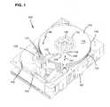
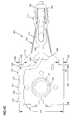
- FIG. 1is a top perspective view of a disc drive in which several discs have been removed to show various features of the disc drive in which embodiments of the present invention may be practiced.
- FIG. 2Ais a top perspective view of a suspension assembly under the prior art.
- FIG. 2Bis a top plan view of a suspension assembly under the prior art.
- FIG. 2Cis a bottom plan view of a suspension assembly under the prior art.
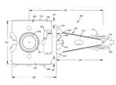
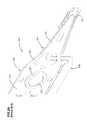
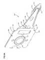
- FIG. 3Ais a top perspective view of one embodiment of a suspension assembly according to principles of the invention.
- FIG. 3Bis a top plan view of the embodiment shown in FIG. 3( a ).
- FIG. 3Cis a bottom plan view of the embodiment shown in FIG. 3( a ).
- FIG. 3Dis a side view of the embodiment that is shown in FIG. 3( a ).
- FIG. 1is an asymmetric view of a disc drive 100 having structure in which principles of the present invention may be practiced.
- the disc drive 100includes a base 102 , and a cover (not shown). Base 102 and the cover form a disc drive enclosure. Extending into base 102 is a spindle motor 106 to which several discs 110 are secured. Each disc 110 is generally angular in shape, with an inner edge 112 and an outer edge 114 circumscribing opposing disc surfaces 116 (of which only one is visible in the drawing) to which data can be stored for later retrieval.
- Base 102provides a cavity or room for disc 110 to be seated in a substantially coaxial arrangement, with an inner wall 118 of the base running around outer edges 114 of disc 110 , substantially transverse to disc surfaces 116 .
- an actuator assembly 120On one side of a pivot 121 , an actuator assembly 120 includes a plurality of arms 122 to which are attached load beams or suspensions 124 . At the end of each suspension 124 is a slider 126 that carries the read/write devices (designated generally by 128 ). The present invention is equally applicable to sliders having different types of read/write devices, such as what is generally referred to as transducers, magneto resistive heads, giant magneto resistive heads, or tunneling magneto resistive heads.
- actuator assembly 120On another side of the pivot, actuator assembly 120 extends to support a voice coil 130 next to one or more magnets 132 fixed relative to base 102 .
- FIGS. 2 A-Care perspective, front, and back views, respectively, of a suspension assembly 200 of the prior art.
- Assembly 200includes a head 202 , a load beam 204 , and a base plate 206 mounted with a boss (not shown).
- Load beam 204includes a rigid portion 210 , a gimbal portion 212 , a base portion 214 and a bend portion 216 .
- Gimbal portion 212supports head 202 via a connection at dimple point 218 of gimbal portion 212 .
- Base portion 214 of load beam 204is sandwiched between base plate 206 and a support arm of the disc drive assembly.
- Base plate 206has a length and a width 220 , 222 , respectively, that is comparable to a length and width 224 , 226 of base portion 214 of load beam 204 .
- Length 220 of base plate 206 in the direction of head 202determines in part a suspension bend length 228 that is measured between an end 207 (see FIG. 2C) of base plate 206 and dimple point 218 of gimbal portion 212 .
- Assembly 200also includes a suspension length 230 that extends from a center axis of a boss hole 232 of base plate 206 to dimple point 218 .
- Width 222 of base plate 206 and width 226 of base portion 214 of load beam 204are configured to provide sufficient structure adjacent boss aperture 232 to support of load beam 204 and head 202 , while being no wider than is necessary so as to keep the weight and mass of the suspension assembly at a minimum.
- Widths 222 , 226are typically sized to match a width of the disc drive assembly support arm at the boss connecting point.
- Known suspension assemblieshave not disclosed a way to increase widths 222 , 226 beyond the width of the disc drive assembly support arm without significantly increasing the weight of the suspension assembly and compromising suspension assembly performance.
- Assembly 200also includes an interconnect 208 having a gimbal portion 240 , a load beam portion 242 , and a base portion 244 .
- Gimbal portion 240is electrically connected with read/write transducers that are mounted on head 202 .
- Gimbal portion 240is typically compliant and free floating in order to permit the necessary flexibility of head 202 relative to load beam 204 .
- load beam portion 242extends along a longitudinal axis of load beam 204 .
- Base portion 244typically extends along a side of base plate 206 and base portion 214 of load beam 204 and is connected to front and rear load beam tabs 234 , 236 that extend from load beam 204 .
- load beam tabs 234 , 236are typically simple extensions of load beam 204 and are thus made from the same relatively compliant material having the same thickness as load beam 204 .
- load beam tabs 234 , 236are subject to bending and torsion forces that may occur from windage within the disc drive assembly, especially when flex circuit 208 is mounted to load beam tabs 234 , 236 .
- the windage forcesincrease, particularly as RPMs of the storage medium increase, interconnects secured to assembly 200 via load beam tabs 234 , 236 , subject the assembly 200 to significant forces that typically increase off track motion of head 202 .
- FIGS. 3 A-Dprovide perspective, top, bottom and side views, respectively, of a example suspension assembly 300 of the invention.
- Assembly 300includes a head 302 , a load beam 304 , a base plate 306 and an interconnect 308 .
- Load beam 304includes a rigid portion 310 , a gimbal portion 312 supporting head 302 , a base portion secured to base plate 306 , and a flexible portion or bend section 316 .
- load beam 304is shown in FIGS. 3 A-D as a planer member without a bend formed therein, load beam 304 is typically bent at bend section 316 so as to provide a preload bend force that is applied between head 302 and the memory medium of the disc drive assembly.
- Base plate 306has a length 320 and a width 322
- base portion 314has a length 324 and a width 326 that are comparable to length and width 320 , 322 .
- Width 322includes a width 351 of first and second base plate shelves 350 , 352 .
- Width 326 of base portion 314also includes a width 355 of first and second load beam shelves 354 , 356 .
- Widths 351 , 355represent the distance the base plate 306 and base portion 314 extend beyond the width of a support arm of the disc drive assembly, which typically corresponds to the width of base plate 226 and load beam base portion 214 shown in the prior art of FIGS. 2 A-C.
- the additional width of the shelves 350 , 352 , 354 , 356 beyond the width of the support armprovide a mounting surface to which the interconnect 308 may extend along and be secured to without interfering with required clearances around boss aperture 332 or interfere with the connection of suspension assembly 300 to the support arm.
- Interconnect 308includes a gimbal portion 340 , a load beam portion 342 and a base portion 344 .
- Gimbal portion 340is electrically connected with head 302 .
- Gimbal portion 340is typically compliant to permit free pivotal movement of head 302 about dimple point 318 .
- Load beam portion 342extends along a longitudinal axis of rigid portion 310 of load beam 304 .
- load beam portion 342is secured at various points along the length of rigid portion 310 while remaining compliant through at least a portion of the flexible portion 316 of load beam 304 to allow unrestricted bending of flexible portion 316 .
- load beam portion 342transitions to a side of base portion 314 so as to extend along load beam shelf 356 and base plate shelf 352 .
- assembly 300includes a reverse load beam orientation, that is, load beam 306 being mounted on the memory medium side of base plate 306 so as to sandwich base plate 306 between load beam portion 314 and the support arm of the disc drive assembly, interconnect 308 is able to extend smoothly and without an interruption in surface structure along load beam 304 from gimbal portion 312 to base portion 314 .
- interconnect 308may not be continuously connected to load beam 304 along an entire length of load beam 304 from gimbal portion 312 to a proximal end 315 (see FIG. 3C) due to aperture 362 and other functional considerations, interconnect 308 may be considered to be secured to load beam 304 along substantially the entire load beam length.
- interconnect 308may extend along load beam 304 from gimbal portion 312 through flexible portion 316 , and then transition to a surface of base plate 306 that is facing the memory medium of disc drive assembly.
- load beam 304does not include first and second load beam shelves 354 , 356 , thus requiring the base portion 344 of interconnect 308 to be secured directly to the first or second base plate shelf 350 , 352 as interconnect 308 extends along length 324 , 320 of load beam 304 and base plate 306 , respectively.
- base portion 344 of interconnect 308may extend along the first base plate shelf 350 and the first load beam shelf 354 .
- Base plate 306may also include an extension 333 that extends in the direction of head 302 .
- Extension 333may provide additional support to load beam 304 at the transition point between base portion 314 and flexible portion 316 .
- Extension 333may provide a reduction in the suspension bend length 328 as compared to the suspension bend length 228 shown in FIG. 2C of the prior art. As discussed earlier, a shorter suspension bend length increases the resonant frequencies of a suspension.
- the additional stiffness inherent with a shorter suspension bend lengthmay be compensated for by making the flexible portion of the suspension load beam more compliant by either removing additional material by increasing the size of an aperture formed in the flexible portion (such as aperture 362 formed in flexible portion 314 ), or by reducing the thickness of the load beam either in the flexible portion 316 alone, or throughout load beam 304 .
- the thickness of the sheet material used for load beam 304is reduced as compared to the thickness of material used for load beam 204 in known load beams.
- a thinner material for load beam 304(given the same type of material) reduces the overall weight of the load beam, which may both provide additional compliance in flexible portion 314 and compensate for the added weight from load beam shelves 354 , 356 .
- Known load beamstypically require a sheet material having a thickness of between 0.002-0.004 inches.
- Load beam 304preferably requires a sheet material having a thickness less than 0.002 inches and most preferably a thickness of 0.0015 inches of stainless steel material. As a result, the net mass of the load beam 304 is about equal to or less than the mass of load beam 204 of the prior art.
- Base plate 306also preferably uses a sheet material having a thickness less than the thickness of material used for base plate 206 of the prior art in order to compensate for the additional width of base plate shelves 350 , 352 and length extension 307 .
- the thickness of known base plate materialis greater than 0.0059 inches, while the thickness of base plate 306 is less than about 0.005 inches, and most preferably about 0.0049 inches thick stainless steel.
- An additional way to reduce the mass or weight of base plate 306is to remove some of the base plate material with an aperture 360 in an area of base plate 306 that has less supporting functionality.
- Base plate 206 of the prior art shown in FIGS. 2 A-Cis approximately square-shaped having a length and width dimension of 0.2 ⁇ 0.2 inches with boss aperture 232 positioned approximately in the center of the square.
- Base plate 306includes an additional 0.03 inches in added width for each of the base plate shelves 350 , 352 for a total of 0.06 inches additional width over width 222 of base plate 206 .
- Base plate 306also includes an additional 0.06 inches in length over length 220 of base plate 206 due to extension 332 .
- boss aperture 332is positioned off center (in a direction away from head 302 ) on the approximately square-shaped base plate 306 . Because of the additional length of extension 333 , suspension bend length 328 can be shortened relative to suspension bend length 228 shown in FIG. 2C.
- base plate 306When assembling base plate 306 , load beam 304 and interconnect 308 together, base plate 306 is first secured, typically with an adhesive or welding, to base portion 314 of bend section 304 .
- Interconnect 308may be secured to load beam 304 and base plate 306 in a variety of different ways including, but not limited to, adhesives, welding, and thermal bonding.
- Base portion 344 of interconnect 308may be laser welded to base portion 314 and base plate 306 at locations 370 , 371 , 372 and multiple other locations along the length of the interconnect. Laser welding is a known method of precisely securing multiple layers together.
- One advantage of the reverse load beam orientation shown in FIGS. 3 A-Dis that the load beam is closer to the memory medium of the disc drive assembly. As a result of the closeness of the load beam to the memory medium, less of a bend is required in the flexible portion of the load beam in order to provide the required pre-load forces between head 302 and the memory medium, as compared to a traditional load beam orientations. Less of a bend in the flexible portion may result in reduced amounts of buckling of the load beam and an increase in lateral stiffening of the load beam as compared to load beams with a greater bend in the flexible portion.
- Interconnect 308 of assembly 300is preferably arranged in such a way relative to base plate 306 and bend section 304 so as to be hidden from a top plan view (see FIG. 3B). As the surface area of interconnect 308 that is unsupported by a section of base plate is reduced to a minimum, assembly 300 becomes less susceptible to windage forces in the plane direction of the memory medium and from windage forces in a normal direction to the memory medium. A suspension assembly that is less susceptible to windage forces may result in improved disc drive performance.
- interconnect 308may be replaced by any number of designs or configurations that extend from the head 302 to a location proximal to base plate 306 .
- interconnect 308may be a twisted pair of wires, or as mentioned above, electrical leads embossed directly on the surface of load beam 304 and base plate 306 .
- suspension 300provides the lowest measured windage induced slider off-track motion among known conventional suspension designs.
- Suspension 300also provides the highest measured first bending frequency, the highest measured first torsion frequency, and the highest measured sway frequency among all known conventional, single state suspension designs.
- the load beam of suspension 300makes use of the thinnest load beam sheet material and the thinnest base plate sheet material among all known conventional suspension designs, thus reducing the assembly mass.
- Suspension 300also provides the highest head slap threshold among known conventional conventional, single stages suspension designs. Consequently, the present invention provides improvements and advantages over the prior art.
Landscapes
- Supporting Of Heads In Record-Carrier Devices (AREA)
Abstract
Description
- This application claims priority from U.S. Provisional Application Serial No. 60/389,816, filed Jun. 18, 2002 and entitled IMPROVED WINDAGE, SHOCK AND LOW MASS CONVENTIONAL SUSPENSION DESIGN.[0001]
- 1. Field of the Invention[0002]
- The present invention relates to data storage devices. In particular, the present invention relates to improving performance of suspension assemblies in data storage devices.[0003]
- 2. Related Art[0004]
- In data storage devices, data is typically stored in tracks on a memory medium. To access the data, the head is positioned within a track of the memory medium while the medium moves beneath the head.[0005]
- In many storage devices, the head is positioned by an actuator assembly that includes a motor that rotates one or more actuator arms. Each actuator arm supports one or two suspensions that each support a head/gimbal assembly. Typically, a suspension includes three distinct areas: a base plate area that connects to the actuator arm, a spring area that provides a vertical spring force to bias the head toward the medium, and a load beam that extends from the spring area to the head/gimbal assembly. A spring force provided by the suspension is designed to allow the head to follow height variations on the surface of the medium without impacting the medium or moving too far away from the medium. Typically, it is desired that the spring area be more elastic or flexible than the remainder of the suspension. However, if the spring area or the remainder of the load beam is too elastic and compliant the load beam will tend to bend and resonate in response to windage induced forces.[0006]
- Windage induced forces have become a particular concern as the performance of disc drives has increased. For example, many high performance drives run at 15 k RPM or higher, causing significant windage forces within the disc drive. Also, there is an increasingly higher number of bits being packed into every square inch of the disc drive surface, leading to a higher number of tracks per inch and a reduced track width. As a result, suspensions are more susceptible to slider off-track motion and other mechanical resonant vibrations that lead to reduced servo bandwidth and reduced track following capabilities of the disc drive.[0007]
- In order to minimize slider off-track motion due to windage, the suspension design may be altered in such a way so as to achieve higher resonance frequencies without compromising on the performance requirements of the disc drive. An effective way to reduce slider off-track motion resulting from windage excitation is to increase the suspension resonant frequencies. Suspension resonance frequencies can be increased by, for example, reducing the length of the suspension, using a thicker sheet of material for the load beam and bend section, or reducing the effective bend length of the suspension. These options have inherent drawbacks and costs that may be significant enough to make them an undesirable option. For example, thicker suspension material is heavier and also deteriorates drive level shock and seek access time performance. Shorter and thicker suspensions usually have very high vertical stiffness that results in additional re-working of the head stack assembly process to achieve the desired gram load to the head/gimbal assembly.[0008]
- Windage driven slider off-track motion may also result from the excitation of the electrical interconnect tail adjacent to the base plate area of the suspension. To minimize this excitation, the tail is usually attached to suspension tabs that extend from the base plate or load beam. However, attaching the interconnect tail to suspension tabs does not completely eliminate the problem as the suspension tabs are typically compliant and asymmetrical, and can translate the windage driven tail motion into slider off-track motion. As mentioned above, the problem of windage induced motion has become a more significant problem as the windage forces increase with increased rotation speeds of the storage medium.[0009]
- A data storage device includes a head and a suspension assembly capable of supporting the head. The suspension assembly includes a base plate having a first base plate surface facing toward the storage medium, and a load beam having a length, a first load beam surface facing toward the storage medium, and a second load beam surface facing toward the first base plate surface. The second load beam surface is secured to the first base plate surface, and an interconnect of the storage device is secured to the first load beam surface along substantially the entire load beam length.[0010]
- In another aspect of the invention, a data storage device for storing and accessing data in tracks on a storage medium includes a head configured to read information from the storage medium and a suspension assembly arranged and configured to support the head. The suspension assembly includes a base plate having a width and a length, a first surface facing the storage medium, and a second surface facing away from the storage medium. The suspension assembly also includes a load beam having a proximal end and a distal end, a first surface facing the storage medium, and a second surface facing away from the storage medium with the proximal end of the load beam being secured to the base plate. The storage device also includes an interconnect extending between the distal end of the load beam and the base plate and physically oriented along the first surface of the load beam and the first surface of the base plate such that the orientation of the interconnect minimizes unstabilizing forces to the suspension assembly.[0011]
- In a yet further aspect of the invention, a head suspension assembly for a disc drive having a storage medium includes a load beam and a base plate. The load beam includes a distal end and a proximal end, a first surface facing away from the storage medium, and a second surface facing toward the storage medium. The base plate includes a length and a width, a first surface facing away from the storage medium, and a second surface facing toward the storage medium. The second surface of the base plate is secured to the first surface of the load beam and the width of the base plate is wide enough to secure an interconnect of the disc drive to the first surface of the base plate.[0012]
- These and various other features as well have advantages that characterize the present invention and will be apparent upon reading of the following detailed description and review of the associated drawings.[0013]
- FIG. 1 is a top perspective view of a disc drive in which several discs have been removed to show various features of the disc drive in which embodiments of the present invention may be practiced.[0014]
- FIG. 2A is a top perspective view of a suspension assembly under the prior art.[0015]
- FIG. 2B is a top plan view of a suspension assembly under the prior art.[0016]
- FIG. 2C is a bottom plan view of a suspension assembly under the prior art.[0017]
- FIG. 3A is a top perspective view of one embodiment of a suspension assembly according to principles of the invention.[0018]
- FIG. 3B is a top plan view of the embodiment shown in FIG. 3([0019]a).
- FIG. 3C is a bottom plan view of the embodiment shown in FIG. 3([0020]a).
- FIG. 3D is a side view of the embodiment that is shown in FIG. 3([0021]a).
- FIG. 1 is an asymmetric view of a[0022]
disc drive 100 having structure in which principles of the present invention may be practiced. Thedisc drive 100 includes abase 102, and a cover (not shown).Base 102 and the cover form a disc drive enclosure. Extending intobase 102 is aspindle motor 106 to whichseveral discs 110 are secured. Eachdisc 110 is generally angular in shape, with aninner edge 112 and anouter edge 114 circumscribing opposing disc surfaces116 (of which only one is visible in the drawing) to which data can be stored for later retrieval.Base 102 provides a cavity or room fordisc 110 to be seated in a substantially coaxial arrangement, with aninner wall 118 of the base running aroundouter edges 114 ofdisc 110, substantially transverse to disc surfaces116. - On one side of a[0023]
pivot 121, anactuator assembly 120 includes a plurality ofarms 122 to which are attached load beams orsuspensions 124. At the end of eachsuspension 124 is aslider 126 that carries the read/write devices (designated generally by128). The present invention is equally applicable to sliders having different types of read/write devices, such as what is generally referred to as transducers, magneto resistive heads, giant magneto resistive heads, or tunneling magneto resistive heads. On another side of the pivot,actuator assembly 120 extends to support avoice coil 130 next to one ormore magnets 132 fixed relative tobase 102. When energized, resultant electromagnetic forces onvoice coil 130cause actuator assembly 120 to rotate aboutpivot 121, thereby bringing the read/write devices into various radio locations relative to disc surfaces116. It can be seen that, withspindle motor 106rotating discs 110 for example, in a direction indicated byarrow 140, andactuator assembly 120 moving read/write heads128 in an arcuate path, as indicated byarrow 142, across disc surfaces116, various locations ondisc surfaces 116 can be accessed by the read/write heads for data recordation or retrieval. - As[0024]
discs 110 are rotated, fluid or air adjacent to disc surfaces110 is also brought into motion, generating air streams or flow currents in the disc drive enclosure. This airflow, or windage, create forces both indirection 140 in the plane of disc surfaces116, as well as a direction normal to the plane ofdisc 116. There also may be various other windage-induced forces occurring throughout the cavity provided bybase 102 and cover104. - FIGS.[0025]2A-C are perspective, front, and back views, respectively, of a
suspension assembly 200 of the prior art.Assembly 200 includes ahead 202, aload beam 204, and abase plate 206 mounted with a boss (not shown).Load beam 204 includes arigid portion 210, agimbal portion 212, abase portion 214 and abend portion 216.Gimbal portion 212 supports head202 via a connection atdimple point 218 ofgimbal portion 212.Base portion 214 ofload beam 204 is sandwiched betweenbase plate 206 and a support arm of the disc drive assembly. - [0026]
Base plate 206 has a length and awidth width base portion 214 ofload beam 204.Length 220 ofbase plate 206 in the direction ofhead 202 determines in part asuspension bend length 228 that is measured between an end207 (see FIG. 2C) ofbase plate 206 anddimple point 218 ofgimbal portion 212.Assembly 200 also includes asuspension length 230 that extends from a center axis of aboss hole 232 ofbase plate 206 todimple point 218. - [0027]
Width 222 ofbase plate 206 andwidth 226 ofbase portion 214 ofload beam 204 are configured to provide sufficient structureadjacent boss aperture 232 to support ofload beam 204 andhead 202, while being no wider than is necessary so as to keep the weight and mass of the suspension assembly at a minimum.Widths widths - [0028]
Assembly 200 also includes aninterconnect 208 having agimbal portion 240, aload beam portion 242, and abase portion 244.Gimbal portion 240 is electrically connected with read/write transducers that are mounted onhead 202.Gimbal portion 240 is typically compliant and free floating in order to permit the necessary flexibility ofhead 202 relative to loadbeam 204. Typically,load beam portion 242 extends along a longitudinal axis ofload beam 204.Base portion 244 typically extends along a side ofbase plate 206 andbase portion 214 ofload beam 204 and is connected to front and rearload beam tabs load beam 204. - As discussed above,[0029]
load beam tabs load beam 204 and are thus made from the same relatively compliant material having the same thickness asload beam 204. As a result of this configuration,load beam tabs flex circuit 208 is mounted to loadbeam tabs assembly 200 viaload beam tabs assembly 200 to significant forces that typically increase off track motion ofhead 202. - FIGS.[0030]3A-D provide perspective, top, bottom and side views, respectively, of a
example suspension assembly 300 of the invention.Assembly 300 includes ahead 302, aload beam 304, abase plate 306 and aninterconnect 308.Load beam 304 includes arigid portion 310, agimbal portion 312 supportinghead 302, a base portion secured tobase plate 306, and a flexible portion orbend section 316. Althoughload beam 304 is shown in FIGS.3A-D as a planer member without a bend formed therein,load beam 304 is typically bent atbend section 316 so as to provide a preload bend force that is applied betweenhead 302 and the memory medium of the disc drive assembly. - [0031]
Base plate 306 has alength 320 and awidth 322, andbase portion 314 has alength 324 and awidth 326 that are comparable to length andwidth Width 322 includes awidth 351 of first and secondbase plate shelves Width 326 ofbase portion 314 also includes awidth 355 of first and secondload beam shelves Widths base plate 306 andbase portion 314 extend beyond the width of a support arm of the disc drive assembly, which typically corresponds to the width ofbase plate 226 and loadbeam base portion 214 shown in the prior art of FIGS.2A-C. The additional width of theshelves interconnect 308 may extend along and be secured to without interfering with required clearances aroundboss aperture 332 or interfere with the connection ofsuspension assembly 300 to the support arm. - [0032]
Interconnect 308 includes agimbal portion 340, aload beam portion 342 and abase portion 344.Gimbal portion 340 is electrically connected withhead 302.Gimbal portion 340 is typically compliant to permit free pivotal movement ofhead 302 aboutdimple point 318.Load beam portion 342 extends along a longitudinal axis ofrigid portion 310 ofload beam 304. Preferably,load beam portion 342 is secured at various points along the length ofrigid portion 310 while remaining compliant through at least a portion of theflexible portion 316 ofload beam 304 to allow unrestricted bending offlexible portion 316. At a point nearflexible portion 316,load beam portion 342 transitions to a side ofbase portion 314 so as to extend alongload beam shelf 356 andbase plate shelf 352. Becauseassembly 300 includes a reverse load beam orientation, that is,load beam 306 being mounted on the memory medium side ofbase plate 306 so as tosandwich base plate 306 betweenload beam portion 314 and the support arm of the disc drive assembly,interconnect 308 is able to extend smoothly and without an interruption in surface structure alongload beam 304 fromgimbal portion 312 tobase portion 314. - Although[0033]
interconnect 308 may not be continuously connected to loadbeam 304 along an entire length ofload beam 304 fromgimbal portion 312 to a proximal end315 (see FIG. 3C) due toaperture 362 and other functional considerations,interconnect 308 may be considered to be secured to loadbeam 304 along substantially the entire load beam length. - In alternative embodiments that do not include a reverse load beam orientation,[0034]
interconnect 308 may extend alongload beam 304 fromgimbal portion 312 throughflexible portion 316, and then transition to a surface ofbase plate 306 that is facing the memory medium of disc drive assembly. In yet further embodiments,load beam 304 does not include first and secondload beam shelves base portion 344 ofinterconnect 308 to be secured directly to the first or secondbase plate shelf interconnect 308 extends alonglength load beam 304 andbase plate 306, respectively. In yet further embodiments,base portion 344 ofinterconnect 308 may extend along the firstbase plate shelf 350 and the firstload beam shelf 354. - [0035]
Base plate 306 may also include anextension 333 that extends in the direction ofhead 302.Extension 333 may provide additional support to loadbeam 304 at the transition point betweenbase portion 314 andflexible portion 316.Extension 333 may provide a reduction in thesuspension bend length 328 as compared to thesuspension bend length 228 shown in FIG. 2C of the prior art. As discussed earlier, a shorter suspension bend length increases the resonant frequencies of a suspension. The additional stiffness inherent with a shorter suspension bend length may be compensated for by making the flexible portion of the suspension load beam more compliant by either removing additional material by increasing the size of an aperture formed in the flexible portion (such asaperture 362 formed in flexible portion314), or by reducing the thickness of the load beam either in theflexible portion 316 alone, or throughoutload beam 304. - Preferably, the thickness of the sheet material used for[0036]
load beam 304 is reduced as compared to the thickness of material used forload beam 204 in known load beams. A thinner material for load beam304 (given the same type of material) reduces the overall weight of the load beam, which may both provide additional compliance inflexible portion 314 and compensate for the added weight fromload beam shelves Load beam 304 preferably requires a sheet material having a thickness less than 0.002 inches and most preferably a thickness of 0.0015 inches of stainless steel material. As a result, the net mass of theload beam 304 is about equal to or less than the mass ofload beam 204 of the prior art. - [0037]
Base plate 306 also preferably uses a sheet material having a thickness less than the thickness of material used forbase plate 206 of the prior art in order to compensate for the additional width ofbase plate shelves length extension 307. The thickness of known base plate material is greater than 0.0059 inches, while the thickness ofbase plate 306 is less than about 0.005 inches, and most preferably about 0.0049 inches thick stainless steel. An additional way to reduce the mass or weight ofbase plate 306 is to remove some of the base plate material with anaperture 360 in an area ofbase plate 306 that has less supporting functionality. - [0038]
Base plate 206 of the prior art shown in FIGS.2A-C is approximately square-shaped having a length and width dimension of 0.2×0.2 inches withboss aperture 232 positioned approximately in the center of the square.Base plate 306 includes an additional 0.03 inches in added width for each of thebase plate shelves width 222 ofbase plate 206.Base plate 306 also includes an additional 0.06 inches in length overlength 220 ofbase plate 206 due toextension 332. In order to maintain the same form factor when assemblingsuspension 300 as compared to the form factor standard in the art,boss aperture 332 is positioned off center (in a direction away from head302) on the approximately square-shapedbase plate 306. Because of the additional length ofextension 333,suspension bend length 328 can be shortened relative tosuspension bend length 228 shown in FIG. 2C. - When assembling[0039]
base plate 306,load beam 304 andinterconnect 308 together,base plate 306 is first secured, typically with an adhesive or welding, tobase portion 314 ofbend section 304.Interconnect 308 may be secured to loadbeam 304 andbase plate 306 in a variety of different ways including, but not limited to, adhesives, welding, and thermal bonding.Base portion 344 ofinterconnect 308 may be laser welded tobase portion 314 andbase plate 306 atlocations - One advantage of the reverse load beam orientation shown in FIGS.[0040]3A-D is that the load beam is closer to the memory medium of the disc drive assembly. As a result of the closeness of the load beam to the memory medium, less of a bend is required in the flexible portion of the load beam in order to provide the required pre-load forces between
head 302 and the memory medium, as compared to a traditional load beam orientations. Less of a bend in the flexible portion may result in reduced amounts of buckling of the load beam and an increase in lateral stiffening of the load beam as compared to load beams with a greater bend in the flexible portion. - Interconnect[0041]308 of
assembly 300 is preferably arranged in such a way relative tobase plate 306 andbend section 304 so as to be hidden from a top plan view (see FIG. 3B). As the surface area ofinterconnect 308 that is unsupported by a section of base plate is reduced to a minimum,assembly 300 becomes less susceptible to windage forces in the plane direction of the memory medium and from windage forces in a normal direction to the memory medium. A suspension assembly that is less susceptible to windage forces may result in improved disc drive performance. - Although the above description has focused on an interconnect that is formed from a flex circuit,[0042]
interconnect 308 may be replaced by any number of designs or configurations that extend from thehead 302 to a location proximal tobase plate 306. For example, interconnect308 may be a twisted pair of wires, or as mentioned above, electrical leads embossed directly on the surface ofload beam 304 andbase plate 306. - The present invention may provide numerous advantages as compared to known suspension assemblies, in particular the prior art shown in FIGS.[0043]2A-C. For example,
suspension 300 provides the lowest measured windage induced slider off-track motion among known conventional suspension designs.Suspension 300 also provides the highest measured first bending frequency, the highest measured first torsion frequency, and the highest measured sway frequency among all known conventional, single state suspension designs. The load beam ofsuspension 300 makes use of the thinnest load beam sheet material and the thinnest base plate sheet material among all known conventional suspension designs, thus reducing the assembly mass.Suspension 300 also provides the highest head slap threshold among known conventional conventional, single stages suspension designs. Consequently, the present invention provides improvements and advantages over the prior art. - The above specification, examples and data provide a complete description of the manufacture and use of the composition of the invention. Since many embodiments of the invention can be made without departing from the spirit and scope of the invention, the invention resides in the claims hereinafter appended.[0044]
Claims (20)
Priority Applications (1)
| Application Number | Priority Date | Filing Date | Title |
|---|---|---|---|
| US10/428,555US20030231432A1 (en) | 2002-06-18 | 2003-05-02 | Windage, shock and low mass conventional suspension design |
Applications Claiming Priority (2)
| Application Number | Priority Date | Filing Date | Title |
|---|---|---|---|
| US38981602P | 2002-06-18 | 2002-06-18 | |
| US10/428,555US20030231432A1 (en) | 2002-06-18 | 2003-05-02 | Windage, shock and low mass conventional suspension design |
Publications (1)
| Publication Number | Publication Date |
|---|---|
| US20030231432A1true US20030231432A1 (en) | 2003-12-18 |
Family
ID=29740181
Family Applications (1)
| Application Number | Title | Priority Date | Filing Date |
|---|---|---|---|
| US10/428,555AbandonedUS20030231432A1 (en) | 2002-06-18 | 2003-05-02 | Windage, shock and low mass conventional suspension design |
Country Status (1)
| Country | Link |
|---|---|
| US (1) | US20030231432A1 (en) |
Cited By (5)
| Publication number | Priority date | Publication date | Assignee | Title |
|---|---|---|---|---|
| US20060007599A1 (en)* | 2004-07-12 | 2006-01-12 | Hitachi Global Storage Technologies Netherlands B.V. | System, method, and apparatus for high performance, four-piece suspension with extended hinge plate |
| US20060193085A1 (en)* | 2005-02-28 | 2006-08-31 | Seagate Technology Llc | Resonance control features for a head gimbal assembly |
| US20130077193A1 (en)* | 2011-09-26 | 2013-03-28 | Suncall Corporation | Magnetic Head Suspension and Manufacturing Method Thereof |
| US9123364B1 (en)* | 2014-03-07 | 2015-09-01 | Seagate Technology Llc | Base plate with relief ring for suspension assembly with modified deformation characteristics |
| US11308982B1 (en)* | 2020-12-18 | 2022-04-19 | Seagate Technology Llc | Curved outer gimbal strut |
Citations (19)
| Publication number | Priority date | Publication date | Assignee | Title |
|---|---|---|---|---|
| US163763A (en)* | 1875-05-25 | Improvement in steam-radiators | ||
| US196581A (en)* | 1877-10-30 | Improvement in lamps | ||
| US4996616A (en)* | 1988-04-22 | 1991-02-26 | International Business Machines Corporation | Head suspension load beam with reinforcing ribs |
| US5057953A (en)* | 1988-03-31 | 1991-10-15 | Applied Magnetics Corporation | Head slider suspension assembly load beam having a fundamental mode vibration characteristic in the range of about 2000 hertz to about 4000 hertz |
| US5079660A (en)* | 1988-07-05 | 1992-01-07 | Mitsubishi Denki Kabushiki Kaisha | Magnetic head suspension assembly for reducing vibration effects |
| US5299081A (en)* | 1992-08-05 | 1994-03-29 | Read-Rite Corporation | Magnetic head suspension assembly |
| US5313353A (en)* | 1991-07-25 | 1994-05-17 | Matsushita Electric Industrial Co. Ltd. | Magnetic head suspension united support arm with ribbed cut-out |
| US5321568A (en)* | 1993-04-22 | 1994-06-14 | Maxtor Corporation | Head suspension assembly with improved pitch and roll characteristics |
| US5446611A (en)* | 1990-09-14 | 1995-08-29 | Hutchinson Technology, Inc. | Head suspension assembly which includes a load beam element having relief channels |
| US5455727A (en)* | 1993-05-25 | 1995-10-03 | Maxtor Corporation | Transducer suspension assembly with a first pair of flanges for raising the resonant frequency and a second pair of flanges for increasing stiffness |
| US5612841A (en)* | 1993-06-15 | 1997-03-18 | Seagate Technology, Inc. | Flexure assembly for hard disc drive heads |
| US5731931A (en)* | 1994-03-22 | 1998-03-24 | Hutchinson Technology Incorporated | Monocoque suspension |
| US5894655A (en)* | 1996-12-31 | 1999-04-20 | Hutchinson Technologies, Inc. | Monocoque head suspension and its method of construction |
| US6014289A (en)* | 1994-03-22 | 2000-01-11 | Hutchinson Technology Incorporated | Integrated circuit on a monocoque suspension |
| US20020063989A1 (en)* | 2000-10-13 | 2002-05-30 | White Andrew D. | Suspension sense capability for windage control |
| US6628481B1 (en)* | 1999-05-05 | 2003-09-30 | Magnecorp Corp. | Load beam opening-mounted chip on suspension |
| US6697226B1 (en)* | 2000-03-31 | 2004-02-24 | Seagate Technology Llc | Disc drive suspension having tip stiffener |
| US7072149B2 (en)* | 2000-02-01 | 2006-07-04 | Matsushita Electric Industrial Co. Ltd. | Head support mechanism and thin film piezoelectric actuator |
| US7136261B2 (en)* | 2002-06-12 | 2006-11-14 | Seagate Technology Llc | Aerodynamically shaped load beam having reduced windage and reduced off-track PES |
- 2003
- 2003-05-02USUS10/428,555patent/US20030231432A1/ennot_activeAbandoned
Patent Citations (20)
| Publication number | Priority date | Publication date | Assignee | Title |
|---|---|---|---|---|
| US163763A (en)* | 1875-05-25 | Improvement in steam-radiators | ||
| US196581A (en)* | 1877-10-30 | Improvement in lamps | ||
| US5057953A (en)* | 1988-03-31 | 1991-10-15 | Applied Magnetics Corporation | Head slider suspension assembly load beam having a fundamental mode vibration characteristic in the range of about 2000 hertz to about 4000 hertz |
| US4996616A (en)* | 1988-04-22 | 1991-02-26 | International Business Machines Corporation | Head suspension load beam with reinforcing ribs |
| US5079660A (en)* | 1988-07-05 | 1992-01-07 | Mitsubishi Denki Kabushiki Kaisha | Magnetic head suspension assembly for reducing vibration effects |
| US5446611A (en)* | 1990-09-14 | 1995-08-29 | Hutchinson Technology, Inc. | Head suspension assembly which includes a load beam element having relief channels |
| US5313353A (en)* | 1991-07-25 | 1994-05-17 | Matsushita Electric Industrial Co. Ltd. | Magnetic head suspension united support arm with ribbed cut-out |
| US5299081A (en)* | 1992-08-05 | 1994-03-29 | Read-Rite Corporation | Magnetic head suspension assembly |
| US5321568A (en)* | 1993-04-22 | 1994-06-14 | Maxtor Corporation | Head suspension assembly with improved pitch and roll characteristics |
| US5455727A (en)* | 1993-05-25 | 1995-10-03 | Maxtor Corporation | Transducer suspension assembly with a first pair of flanges for raising the resonant frequency and a second pair of flanges for increasing stiffness |
| US5612841A (en)* | 1993-06-15 | 1997-03-18 | Seagate Technology, Inc. | Flexure assembly for hard disc drive heads |
| US5731931A (en)* | 1994-03-22 | 1998-03-24 | Hutchinson Technology Incorporated | Monocoque suspension |
| US6014289A (en)* | 1994-03-22 | 2000-01-11 | Hutchinson Technology Incorporated | Integrated circuit on a monocoque suspension |
| US5894655A (en)* | 1996-12-31 | 1999-04-20 | Hutchinson Technologies, Inc. | Monocoque head suspension and its method of construction |
| US6628481B1 (en)* | 1999-05-05 | 2003-09-30 | Magnecorp Corp. | Load beam opening-mounted chip on suspension |
| US7072149B2 (en)* | 2000-02-01 | 2006-07-04 | Matsushita Electric Industrial Co. Ltd. | Head support mechanism and thin film piezoelectric actuator |
| US7072150B2 (en)* | 2000-02-01 | 2006-07-04 | Matsushita Electric Industrial Co., Ltd. | Head support mechanism and thin film piezoelectric actuator |
| US6697226B1 (en)* | 2000-03-31 | 2004-02-24 | Seagate Technology Llc | Disc drive suspension having tip stiffener |
| US20020063989A1 (en)* | 2000-10-13 | 2002-05-30 | White Andrew D. | Suspension sense capability for windage control |
| US7136261B2 (en)* | 2002-06-12 | 2006-11-14 | Seagate Technology Llc | Aerodynamically shaped load beam having reduced windage and reduced off-track PES |
Cited By (7)
| Publication number | Priority date | Publication date | Assignee | Title |
|---|---|---|---|---|
| US20060007599A1 (en)* | 2004-07-12 | 2006-01-12 | Hitachi Global Storage Technologies Netherlands B.V. | System, method, and apparatus for high performance, four-piece suspension with extended hinge plate |
| US20060193085A1 (en)* | 2005-02-28 | 2006-08-31 | Seagate Technology Llc | Resonance control features for a head gimbal assembly |
| US7663841B2 (en) | 2005-02-28 | 2010-02-16 | Seagate Technology Llc | Resonance control features for a head gimbal assembly |
| US20130077193A1 (en)* | 2011-09-26 | 2013-03-28 | Suncall Corporation | Magnetic Head Suspension and Manufacturing Method Thereof |
| US8520340B2 (en)* | 2011-09-26 | 2013-08-27 | Suncall Corporation | Magnetic head suspension and manufacturing method thereof |
| US9123364B1 (en)* | 2014-03-07 | 2015-09-01 | Seagate Technology Llc | Base plate with relief ring for suspension assembly with modified deformation characteristics |
| US11308982B1 (en)* | 2020-12-18 | 2022-04-19 | Seagate Technology Llc | Curved outer gimbal strut |
Similar Documents
| Publication | Publication Date | Title |
|---|---|---|
| EP0302615B1 (en) | A head suspension assembly for a magnetic record disk store | |
| US6055132A (en) | Integrated lead suspension flexure for attaching a micro-actuator with a transducer slider | |
| JP3328800B2 (en) | Head suspension | |
| US7050270B1 (en) | Disk drive actuator arm assembly having a portion of the arm at a greater distance from a disk recording surface than the arm tip portion | |
| US6515832B1 (en) | Gimbal stiffness control for head suspension assemblies | |
| US5956209A (en) | Integrated suspension flexure having a compliant tip termination platform | |
| US6493192B2 (en) | Disc drive with improved head pitch adjustment | |
| US7636222B1 (en) | Tuned mass actuator arms for decreasing track misregistration in a depopulated head suspension disk drive | |
| US20080144225A1 (en) | Techniques for reducing flexure distortion and gimbal separation for thin-film PZT micro-actuators of head gimbal assemblies | |
| US20090268347A1 (en) | Suspension and disk drive | |
| US6021022A (en) | Flexure displacement limiter-flex circuit interconnect | |
| US5909342A (en) | Planar flexible circuit package for coupling transducers with carriage mounted circuitry | |
| JPH0798949A (en) | Suspension system | |
| US8582243B2 (en) | Suspension with supporting pieces, head gimbal assembly and disk drive unit with the same | |
| US20110090600A1 (en) | Suspension, head gimbal assembly and disk drive unit with the same | |
| US7209325B2 (en) | Suspension damping method with minimum impact on preload stiffness | |
| KR100723533B1 (en) | HAS and its hard disk drive | |
| US6747849B1 (en) | High performance suspension with reduced flow-induced vibration | |
| JP7742838B2 (en) | Three-stage design for actuator mounting process on flexure | |
| US5940251A (en) | Head suspension with dynamic vibration absorption extension | |
| US5953180A (en) | Multi-mode suspension populated actuator for a disk drive | |
| US7136261B2 (en) | Aerodynamically shaped load beam having reduced windage and reduced off-track PES | |
| US6473272B1 (en) | Dynammically symmetric actuator | |
| US20030231432A1 (en) | Windage, shock and low mass conventional suspension design | |
| US6215627B1 (en) | Suspension assembly gimbal load beam stiffener |
Legal Events
| Date | Code | Title | Description |
|---|---|---|---|
| AS | Assignment | Owner name:SEAGATE TECHNOLOGY LLC, CALIFORNIA Free format text:ASSIGNMENT OF ASSIGNORS INTEREST;ASSIGNORS:BHATTACHARYA, SANDEEPAN;HUTCHINSON, ANDREW JOHN;REEL/FRAME:014040/0489 Effective date:20030428 | |
| STCB | Information on status: application discontinuation | Free format text:ABANDONED -- FAILURE TO PAY ISSUE FEE | |
| AS | Assignment | Owner name:WELLS FARGO BANK, NATIONAL ASSOCIATION, AS COLLATERAL AGENT AND SECOND PRIORITY REPRESENTATIVE, CALIFORNIA Free format text:SECURITY AGREEMENT;ASSIGNORS:MAXTOR CORPORATION;SEAGATE TECHNOLOGY LLC;SEAGATE TECHNOLOGY INTERNATIONAL;REEL/FRAME:022757/0017 Effective date:20090507 Owner name:JPMORGAN CHASE BANK, N.A., AS ADMINISTRATIVE AGENT AND FIRST PRIORITY REPRESENTATIVE, NEW YORK Free format text:SECURITY AGREEMENT;ASSIGNORS:MAXTOR CORPORATION;SEAGATE TECHNOLOGY LLC;SEAGATE TECHNOLOGY INTERNATIONAL;REEL/FRAME:022757/0017 Effective date:20090507 Owner name:JPMORGAN CHASE BANK, N.A., AS ADMINISTRATIVE AGENT Free format text:SECURITY AGREEMENT;ASSIGNORS:MAXTOR CORPORATION;SEAGATE TECHNOLOGY LLC;SEAGATE TECHNOLOGY INTERNATIONAL;REEL/FRAME:022757/0017 Effective date:20090507 Owner name:WELLS FARGO BANK, NATIONAL ASSOCIATION, AS COLLATE Free format text:SECURITY AGREEMENT;ASSIGNORS:MAXTOR CORPORATION;SEAGATE TECHNOLOGY LLC;SEAGATE TECHNOLOGY INTERNATIONAL;REEL/FRAME:022757/0017 Effective date:20090507 | |
| AS | Assignment | Owner name:SEAGATE TECHNOLOGY HDD HOLDINGS, CALIFORNIA Free format text:RELEASE;ASSIGNOR:JPMORGAN CHASE BANK, N.A., AS ADMINISTRATIVE AGENT;REEL/FRAME:025662/0001 Effective date:20110114 Owner name:SEAGATE TECHNOLOGY LLC, CALIFORNIA Free format text:RELEASE;ASSIGNOR:JPMORGAN CHASE BANK, N.A., AS ADMINISTRATIVE AGENT;REEL/FRAME:025662/0001 Effective date:20110114 Owner name:SEAGATE TECHNOLOGY INTERNATIONAL, CALIFORNIA Free format text:RELEASE;ASSIGNOR:JPMORGAN CHASE BANK, N.A., AS ADMINISTRATIVE AGENT;REEL/FRAME:025662/0001 Effective date:20110114 Owner name:MAXTOR CORPORATION, CALIFORNIA Free format text:RELEASE;ASSIGNOR:JPMORGAN CHASE BANK, N.A., AS ADMINISTRATIVE AGENT;REEL/FRAME:025662/0001 Effective date:20110114 | |
| AS | Assignment | Owner name:SEAGATE TECHNOLOGY LLC, CALIFORNIA Free format text:TERMINATION AND RELEASE OF SECURITY INTEREST IN PATENT RIGHTS;ASSIGNOR:WELLS FARGO BANK, NATIONAL ASSOCIATION, AS COLLATERAL AGENT AND SECOND PRIORITY REPRESENTATIVE;REEL/FRAME:030833/0001 Effective date:20130312 Owner name:SEAGATE TECHNOLOGY US HOLDINGS, INC., CALIFORNIA Free format text:TERMINATION AND RELEASE OF SECURITY INTEREST IN PATENT RIGHTS;ASSIGNOR:WELLS FARGO BANK, NATIONAL ASSOCIATION, AS COLLATERAL AGENT AND SECOND PRIORITY REPRESENTATIVE;REEL/FRAME:030833/0001 Effective date:20130312 Owner name:EVAULT INC. (F/K/A I365 INC.), CALIFORNIA Free format text:TERMINATION AND RELEASE OF SECURITY INTEREST IN PATENT RIGHTS;ASSIGNOR:WELLS FARGO BANK, NATIONAL ASSOCIATION, AS COLLATERAL AGENT AND SECOND PRIORITY REPRESENTATIVE;REEL/FRAME:030833/0001 Effective date:20130312 Owner name:SEAGATE TECHNOLOGY INTERNATIONAL, CAYMAN ISLANDS Free format text:TERMINATION AND RELEASE OF SECURITY INTEREST IN PATENT RIGHTS;ASSIGNOR:WELLS FARGO BANK, NATIONAL ASSOCIATION, AS COLLATERAL AGENT AND SECOND PRIORITY REPRESENTATIVE;REEL/FRAME:030833/0001 Effective date:20130312 |