US20030229308A1 - Injector adapter and combination thereof - Google Patents
Injector adapter and combination thereofDownload PDFInfo
- Publication number
- US20030229308A1 US20030229308A1US10/453,072US45307203AUS2003229308A1US 20030229308 A1US20030229308 A1US 20030229308A1US 45307203 AUS45307203 AUS 45307203AUS 2003229308 A1US2003229308 A1US 2003229308A1
- Authority
- US
- United States
- Prior art keywords
- living
- pair
- skin
- opposing surfaces
- injector
- Prior art date
- Legal status (The legal status is an assumption and is not a legal conclusion. Google has not performed a legal analysis and makes no representation as to the accuracy of the status listed.)
- Abandoned
Links
Images


Classifications
- A—HUMAN NECESSITIES
- A61—MEDICAL OR VETERINARY SCIENCE; HYGIENE
- A61M—DEVICES FOR INTRODUCING MEDIA INTO, OR ONTO, THE BODY; DEVICES FOR TRANSDUCING BODY MEDIA OR FOR TAKING MEDIA FROM THE BODY; DEVICES FOR PRODUCING OR ENDING SLEEP OR STUPOR
- A61M5/00—Devices for bringing media into the body in a subcutaneous, intra-vascular or intramuscular way; Accessories therefor, e.g. filling or cleaning devices, arm-rests
- A61M5/178—Syringes
- A61M5/20—Automatic syringes, e.g. with automatically actuated piston rod, with automatic needle injection, filling automatically
- A61M2005/206—With automatic needle insertion
- A—HUMAN NECESSITIES
- A61—MEDICAL OR VETERINARY SCIENCE; HYGIENE
- A61M—DEVICES FOR INTRODUCING MEDIA INTO, OR ONTO, THE BODY; DEVICES FOR TRANSDUCING BODY MEDIA OR FOR TAKING MEDIA FROM THE BODY; DEVICES FOR PRODUCING OR ENDING SLEEP OR STUPOR
- A61M5/00—Devices for bringing media into the body in a subcutaneous, intra-vascular or intramuscular way; Accessories therefor, e.g. filling or cleaning devices, arm-rests
- A61M5/178—Syringes
- A61M5/20—Automatic syringes, e.g. with automatically actuated piston rod, with automatic needle injection, filling automatically
- A61M2005/2073—Automatic syringes, e.g. with automatically actuated piston rod, with automatic needle injection, filling automatically preventing premature release, e.g. by making use of a safety lock
- A61M2005/208—Release is possible only when device is pushed against the skin, e.g. using a trigger which is blocked or inactive when the device is not pushed against the skin
- A—HUMAN NECESSITIES
- A61—MEDICAL OR VETERINARY SCIENCE; HYGIENE
- A61M—DEVICES FOR INTRODUCING MEDIA INTO, OR ONTO, THE BODY; DEVICES FOR TRANSDUCING BODY MEDIA OR FOR TAKING MEDIA FROM THE BODY; DEVICES FOR PRODUCING OR ENDING SLEEP OR STUPOR
- A61M5/00—Devices for bringing media into the body in a subcutaneous, intra-vascular or intramuscular way; Accessories therefor, e.g. filling or cleaning devices, arm-rests
- A61M5/178—Syringes
- A61M5/31—Details
- A61M5/32—Needles; Details of needles pertaining to their connection with syringe or hub; Accessories for bringing the needle into, or holding the needle on, the body; Devices for protection of needles
- A61M5/3287—Accessories for bringing the needle into the body; Automatic needle insertion
Definitions
- the present inventionrelates to the administration of a drug solution and, more particularly, to the delivery of a viscous drug solution into a mammal.
- the slowing down of injection rateis especially essential with the injection of viscous drug or other drugs that are difficult for tissue absorption.
- a level of painusually follows injection due to the tissue's inability to quickly absorb the solution.
- a reduction of the injection rateis important for the injection of viscous drugs or other drugs that are difficult for tissue absorption because, in many cases, pain is the result of rate differences between the injection rate and the absorption rate.
- Other reasons for the reduced injection rateinclude the prevention of an adverse reaction due to rapid compound injection and the provision for lower injection forces needed for viscous compounds.
- PCT International Patent No. WO 96/24398discloses a needle-less injector that utilizes a pressure pad for evenly distributing the contact pressure of the injector when it is placed on the skin but also does not teach or suggest supporting the needle-less injector on its own for a prolonged period of time.
- U.S. Pat. No. 6,332,875discloses a hand-held injection device that facilitates the injection of manually-operated syringes or pens.
- An apparatus for use with an automatic injectore.g., any injector that automatically delivers a solution to a living being including automatic syringes, automatic needle-less injectors, etc., for injecting a solution into a living being.
- an automatic injectore.g., any injector that automatically delivers a solution to a living being including automatic syringes, automatic needle-less injectors, etc., for injecting a solution into a living being.
- the apparatuscomprises: an injector-receiving member (e.g., a collar or sleeve) for receiving a portion of a housing of the automatic injector; and a living being-engaging member (e.g., a substantially flat base surface) forming one end of the injector-receiving member and including releasable coupling means (e.g., a biocompatible adhesive layer) for releasably coupling the apparatus to the living being, and wherein the living being-engaging member comprises an aperture for permitting passage of the solution from the automatic injector, when activated, into the skin of the living being.
- an injector-receiving membere.g., a collar or sleeve
- a living being-engaging membere.g., a substantially flat base surface
- a method for delivering a solution to a living being using an automatic injectore.g., any injector that automatically delivers a solution to a living being including automatic syringes, automatic needle-less injectors, etc., having an output for dispensing the solution.
- an automatic injectore.g., any injector that automatically delivers a solution to a living being including automatic syringes, automatic needle-less injectors, etc., having an output for dispensing the solution.
- the methodcomprises the steps of: coupling a rigid structure (e.g., a substantially flat base portion having a collar or sleeve member forming a part thereof) to the skin of the living being, and wherein the rigid structure has an aperture in a portion thereof (e.g., in the substantially flat base portion) that couples to the skin of the living being; coupling the automatic injector to the rigid structure; and activating the automatic injector to cause the solution to pass from the output, through the aperture and into the skin.
- a rigid structuree.g., a substantially flat base portion having a collar or sleeve member forming a part thereof
- An apparatus for automatically delivering a solution to a living beingcomprises: an automatic injector (e.g., any injector that automatically delivers a solution to a living being including automatic syringes, automatic needle-less injectors, etc.,) having a housing with a proximal and distal end, wherein the proximal end comprises a skin-engaging surface and a hole for permitting the solution to pass therethrough; the skin-engaging surface comprises releasable coupling means for releasably coupling the apparatus to the living being; and wherein the apparatus delivers the solution, when activated, through the skin of the living being without the need for a person to hold the apparatus during solution delivery.
- an automatic injectore.g., any injector that automatically delivers a solution to a living being including automatic syringes, automatic needle-less injectors, etc., having a housing with a proximal and distal end, wherein the proximal end comprises a skin-engaging surface and a
- a method for automatically injecting a solution into a living beingcomprising the steps of: coupling a proximal end of an automatic injector (e.g., any injector that automatically delivers a solution to a living being including automatic syringes, automatic needle-less injectors, etc.,) to the skin of the living being, wherein the automatic injector has an aperture in the proximal end that is coupled to the skin of the living being; and activating the automatic injector to cause the solution to pass through the hole and into the skin and without the need for a person to hold the automatic injector during solution delivery.
- an automatic injectore.g., any injector that automatically delivers a solution to a living being including automatic syringes, automatic needle-less injectors, etc.
- FIG. 1is an isometric view of the injector adapter of the present invention
- FIG. 2is an isometric view of the injector adapter including an exploded view of a preferred adhesion system that is coupled to the base portion of the injector adapter for releasably coupling the injector adapter to the skin of a living being;
- FIG. 2Ais an isometric view of the preferred adhesion system of FIG. 2;
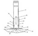
- FIG. 3is an exploded view showing an automatic injector and the injector adapter, with the injector adapter already applied to the skin of a living being;
- FIG. 4depicts the automatic injector engaged with injector adapter, shown in cross-section, and with the automatic injector being activated to make the injection into the skin;
- FIG. 5depicts the automatic injector engaged with another embodiment of the injector adapter having a shortened injector-receiving portion, shown in cross-section, and with the automatic injector being activated to make the injection into the skin;
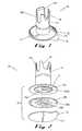
- FIG. 6is an isometric view of another embodiment of the injector adapter using the shortened injector-receiving portion, showing a release sheet tab projecting from the base of the adapter;
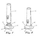
- FIG. 7is an exploded view showing another automatic injector and the injector adapter of FIG. 6 before the adapter is applied to the skin;
- FIG. 8depicts the automatic injector engaged with injector adapter of FIG. 6 but with the release sheet still covering the base of the adapter;
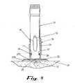
- FIG. 9depicts a bottom isometric view of the injector adapter using the shortened injector-receiving portion of FIGS. 5 - 8 and including the preferred adhesion system;
- FIG. 10is a side elevation view of an integrated injector adapter of the present invention.
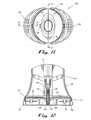
- FIG. 11is a top view of the integrated injector adapter
- FIG. 12is a partial cross-sectional view of the lower portion of the integrated injector adapter taken along line 12 - 12 of FIG. 11;
- FIG. 13 ais a top view of the clip of the integrated injector adapter
- FIG. 13 bis a bottom view of the clip the integrated injector adapter
- FIG. 14is a partial cross-sectional view of one snap of the clip engaged with the body-engaging portion of the integrated injector adapter taken along line 14 - 14 of FIG. 13 a;
- FIG. 15is a top view of the release liner of the integrated injector adapter.
- FIG. 16is a partial isometric and cross-sectional view of the upper portion of the clip of the integrated injector adaptor illustrating how a tab of the release liner is secured to the clip.
- the injector adapter 20permits the automatic injector to be attached to the skin of the living being, without the need for the patient or an attendant (hereinafter “user”) to hold the injector, for the required duration of the slow injection. Furthermore, it is within the broadest scope of this invention that the injector adapter 20 be universal.
- the injector adapter 20can be applied to a range of conventional automatic injectors where the delivery of a highly viscous drug is required, and/or where the time of drug delivery is longer than a conventional automatic injector delivering a bolus and/or where manual injection by the patient is not possible and assistance is needed in the form of the adapter 20 .
- the high viscosity of some drug solutionssubstantially increases the injection time.
- Injection timeis the result of the level of pressure applied to the drug volume, the physical attributes of the drug including viscosity, and the fluid path geometry such as the needle's inner diameter and length, as well as delivery volume. Injection time, in most cases, is a device control parameter though in some cases the tissue also affects it by creating significant backpressure.
- a modified devicewould be used to slow down the delivery rate and to increase the delivery time.
- the injection timecould reach into tens of minutes. It is not possible for the patient to reliably keep an injector pressed against the skin for an extended time.
- the injector adapter 20solves this problem.
- FIG. 1an injector adapter that couples to the skin of a living being and permits an automatic injector to be coupled thereto without the need for an attendant to hold the automatic injector during drug delivery to the living being; especially in cases where the injection of the drug solution must be delivered slowly over a long period of time (e.g., approximately 10 minutes).
- the injector adapter 20basically comprises a base portion 22 and an injector receiving portion 24 .
- the base portion 22couples to the skin 26 of a living being and an automatic injector 10 is releasably coupled to the injector receiving portion 24 .
- automatic injectorsthat can be used with the injector adapter 20 are those disclosed in U.S.A.S. No. 60/334,294 filed on Nov. 30, 2001 entitled AUTOMATIC INJECTOR and whose entire disclosure is incorporated by reference herein. It should be understood that it is within the broadest scope of this invention to have the injector adapter 20 be used with any automatic injector and that the examples cited in No.
- 60/334,294do not limit the use of the injector adapter 20 to only those automatic injectors.
- the term “automatic injector” as used throughout this Specificationis meant to include any injector that automatically delivers a material to a living being and therefore includes automatic injectors that do not automatically retract an injection needle (also referred to as “automatic syringes”) and also includes automatic needle-less injectors.
- the preferred embodiment of the injector adapter 20comprises a unitized base portion 22 and injector receiving portion 24 that can be formed using any well-known rigid material (e.g., plastic), although it is within the broadest scope of the invention 20 to have the base portion 22 and the injector-receiving portion 24 be two separate pieces that can be assembled into the injector adapter 20 .
- the injector adapter 20forms a disposable unit, as do the automatic injectors that are used with the injector adapter 20 .
- the base portion 22forms a substantially flat surface and comprises a hole 28 (FIGS. 4 - 5 ) that permits a needle 12 (FIG. 4) to pass through the base portion 22 and into the skin 26 for the injection; alternatively, when a needle-less automatic injector (not shown) is used, the hole 28 permits the passage of the drug solution from the output of the needle-less automatic injector, through the base portion 22 and into the skin 26 .
- the base portion 22is circular in shape (e.g., 60 mm diameter) and, in the preferred embodiment, adheres to the skin 26 of the living being using, preferably, an adhesive system 27 (FIGS. 2 - 2 A) applied to the underside of the base portion 22 to maintain the automatic injector 10 pressed against the skin 26 of the living being for an extended time.
- the adhesive system 27comprises a double-sided adhesion layer 27 A, a biocompatible single-side adhesion layer 27 B and a liner 27 C.
- the double-sided adhesion layer 27 Ae.g., Avery Dennison FT-1115
- the non-adhesive side 27 B 1(a portion of which is shown in FIG.
- the biocompatible single-side adhesion layer 27 B(e.g., Kendall FM100) is secured against the other side 27 A 2 of the double-sided adhesion layer 27 A; similarly, the biocompatible single-side adhesion layer 27 B also comprises a hole 28 B that aligns with holes 28 / 28 A to permit passage of the drug or needle (not shown).
- the liner 27 C having a pull tab 32is releasably coupled to biocompatible adhesive side 27 B 2 to cover side 27 B 2 until that side 27 B 2 is ready to be coupled to the skin 26 . As can be seen from FIGS.
- the biocompatible single-side adhesion layer 27 Bis larger than the double-sided adhesion layer 27 A, thereby forming a “skirt” or “ring” 30 that is not adhered to the base portion 22 .
- the adhesive system 27(FIG. 2A) is applied to the base portion 22 and is ready for use as shown in FIG. 1.
- the injector adapter 20seizes the tab 32 on the liner 27 C and pulls it away from the base portion 22 , thereby exposing the biocompatible adhesive side 27 B 2 . Once the liner 27 C is removed, the injector adapter 20 can then be adhered to the injection site on the skin 26 .
- This wiping procedureapparently reduces the levels of oil and particulate matter in the site area which enhances the ability of the biocompatible adhesive side 27 B 2 to hold the injector adapter 20 in place for a long period of time (e.g., 10 minutes).
- the injector receiving portion 24 of the injector adapter 20in the preferred embodiment, basically comprises a collar or neck that receives the working end 14 of the automatic injector 10 .
- the collar/sleeveis circular in shape (e.g., inside diameter 24 mm) in order to correspond with the circular shaped working end 14 of the injector 10 .
- the collar/sleevemay be a non-circular shape (e.g., oval) so long as it corresponds in shape with the working end of the injector 10 .
- the injector receiving portion 24include means for engaging and disengaging.
- the injector adapter 20can be a non-disposable unit and therefore used again, disengagement from the automatic injector 10 is then required.
- the working end 14 of the injector 10may include tabs, undercuts, and cutouts in the collar/sleeve to permit unobstructed operation of any injector triggers or visual access to any drug windows when the injector 10 is engaged with the injector adapter 20 .
- the injector adapter 20can have design features that match a selected automatic injector design.
- an automatic injector 10comprises a slidable injection trigger 16 along the working end 14
- the injector receiving portion 24comprises a cutout 34 (or opening, aperture, gap, etc.) to allow the attendant to operate the trigger 16 once the working end 14 is coupled to the injector adapter 20 .
- FIG. 4shows the trigger 16 being in a downward position, thereby extending the needle 12 downward, through the hole 28 and into the skin 26 .
- the automatic injector 10comprises a slit/cavity 17 (see FIGS. 3 - 4 ) at the working end 14
- a corresponding catch 36FIG.
- a corresponding cutout 34 A(FIG. 1, or other cutout, opening, aperture, gap, etc.) in the injector receiving portion 24 provides visual access to the user during the injection process to permit the user to know the level of drug still within the injector 10 ; the injector receiving portion 24 may include other cutouts 34 B (FIG. 1) that permit visual access to other portions of the working end 14 of the injector 10 when it is engaged in the injector receiving portion 24 .
- the automatic injector 10comprises a body sensing element 11 that normally retracts when the injector 10 is directly pressed against the skin of the living being, this retraction is not obstructed when the injector 10 is coupled to the injector adapter 20 .
- the base portion 22provides the body sensing element 11 with a firm surface to push against; in addition, this retraction action of the body element 11 operates to cause a snap cooperation of the slit/cavity 17 and the catches 36 to support the engagement/disengagement of the working end 14 within the injector receiving portion 24 .
- this snap cooperationalso aligns the retracted injection needle 12 with the hole 28 (as well as holes 28 A- 28 B in the adhesion system 27 ) in preparation for injection.
- the automatic injector 10can then be used in its normal operation (i.e., needle penetration, drug delivery, needle retraction by the end of delivery) as if it were placed directly against the skin, but without the need to hold the injector 10 in place during injection.
- the automatic injector 10be vertically oriented during the injection process (as shown in FIG. 4), e.g., the living being can be in a prone position, it is not required. If the living being is a human, the patient can be in a sitting, reclining or even in an upright position.
- the preferred embodiment of the injector adapter 20has the injector receiving portion 24 perpendicular to the base portion 22 , thereby creating an injection that is normal to the skin surface. It is within the broadest scope of the invention 20 though, to include other angular orientations of the injection to the skin using the injector adapter 20 .
- the key feature of the present invention 20is that it provides a secure coupling of the automatic injector 10 to the living being during injection without the need for an attendant to hold the injector 10 during injection, thereby preventing any needle movements in the tissue during injection.
- FIG. 5An alternative embodiment of the injector adapter 20 is shown in FIG. 5 whereby the injector receiving portion 24 ′ of the injector adapter 20 is shortened in height. This shortened height 38 facilitates packaging and storing of the injector adapter 20 . It also alleviates the need to provide a cutout 34 (or opening, aperture, gap, etc.) in the collar/sleeve as discussed earlier. And although the neck/collar is shortened, the injector-receiving portion 24 still operates to couple a smaller sized working end of the injector 10 using the snap cooperation of the slit/cavity 17 and the catches 36 .
- FIG. 6 - 8show the use of the injector adapter 20 using another type of shortened injector receiving portion 24 ′′ with a different type of automatic injector 10 ′.
- the release sheet 27 Calso comprises a slightly-modified tab 32 ′ which includes a grasping hole 33 .
- FIG. 9shows the injector adapter 20 using either of the shortened injector receiving portions 24 ′ or 24 ′′ and the adhesive system 27 coupled to the base portion 22 , with the liner 27 C already removed.
- injector adapter 20is an integrated injector/adapter configuration as shown in FIG. 10 using the reference number 120 , whereby the adapter is incorporated into the automatic injector itself at its proximal end.
- the integrated injector adapter 120reduces the number of steps and simplifies the injection process. This is of critical importance for patients with limited dexterity, including rheumatoid arthritis (RA) and multiple sclerosis (MS) patients.
- RArheumatoid arthritis
- MSmultiple sclerosis
- the userwould then normally apply the injector adapter 20 to the injection site (after thoroughly wiping the site with alcohol, as discussed earlier) by pulling the tab 32 of the release sheet 27 C and applying the injector adapter 20 at the site.
- the userwould prepare the automatic injector 10 in accordance with the accompanying instructions of that particular injector 10 (e.g., inserting a drug cartridge, removing any needle protector means, etc.). Once the injector 10 is ready for use, the user would then insert the working end 14 of the injector 10 , as discussed previously. In contrast, using the integrated injector adapter 120 , the user would remove the combined automatic injector/adapter 120 from a single package.
- the removal of the release sheet 27 C from the base portion 22 of the integrated injector adapter 120simultaneously removes the needle protector means. Because the automatic injector 10 already comprises the base portion 22 , the step of inserting the automatic injector 10 into the adapter is omitted.
- the integrated injector adapter 120comprises an injector 122 , a trigger button 124 , a safety tab 126 , an observation window 128 , the body-engaging portion 130 , a liner 132 and a clip 134 .
- a form or bond line 129is shown between the injector 122 housing and the body-engaging portion 130 .
- the clip 134is pulled away from the body-engaging portion 130 when the device 120 is ready to be applied to the skin 126 of the living being.
- a flat base surface 125(FIG. 12) is exposed for engaging the skin 126 of the living being.
- the injector 122contains a pre-filled syringe 121 (e.g., a pre-filled HYPAK® syringe, such as a 1 ml “short” version),having a needle 136 attached thereto and a removable needle protector 138 (e.g., a rubber sterility protector) covering the needle 136 .
- a pre-filled syringe 121e.g., a pre-filled HYPAK® syringe, such as a 1 ml “short” version
- a removable needle protector 138e.g., a rubber sterility protector
- the needle protector 138is also pulled away from the needle 136 , while the needle 136 remains retracted within the body-engaging portion 130 , in preparation for the injection.
- FIG. 13 aprovides a top view of the clip 134 (removed from the integrated injector adapter 120 ) showing the opening 145 containing the latches 144 therein.
- a pair of snaps 146 A/ 146 B on opposing sides of the clip 134releasably engage corresponding recesses in the lower portion of the body engaging portion 130 , as shown most clearly in FIG. 14 which shows only one of the snaps 146 B/corresponding recess 148 B, it being understood that the other snap 146 A releasably engages into a corresponding recess on the opposite side of the body engaging portion 130 .
- the clip 134has a gripping surface 135 (FIG. 13 a ) which helps an RA or MS patient seize the clip 134 in order to remove it.
- FIG. 15provides a top view of the release liner 132 which covers the flat base surface 125 before use of the integrated injector adapter 120 .
- an adhesive systemsimilar to adhesive system 27 , is applied to the underside surface of the flattened base surface 125 and includes a biocompatible single-side adhesion layer (similar to layer 27 B discussed earlier) that is covered with the release liner 132 .
- a hole 150is provided in the release liner 132 to permit the removal of the needle protector 138 when the clip 134 is pulled away.
- the release liner 132comprises holes 152 on opposite sides of the release liner 132 which are connected to clip 134 via respective pins 154 (only one of which is shown in FIG.
- the pre-filled syringe 121is positioned within the injector 122 housing and positioned through the hole 140 in the body-engaging portion 130 .
- the release liner 132is installed on the flat base surface 125 and the clip 134 is coupled to the body-engaging portion 130 .
- the userwipes the injection site thoroughly with alcohol. The user then seizes the gripping surface 135 of the clip 134 and pulls the clip 134 away from the integrated injector adapter 120 , which exposes the biocompatible single-side adhesion layer (similar to layer 27 B discussed earlier).
- the userthen presses the flat base surface 125 against the injection site to cause the integrated injector adapter 120 to adhere to the injection site.
- the userthen removes the safety tab 126 ; the safety tab 126 prevents false activation of the integrated injector adapter 120 .
- some automatic injectors 10use a body-sensing element 11 (FIG. 3) as a method to prevent false activation. Where the integrated injector adapter 120 is used, such a body-sensing element is replaced by the safety tab 126 .
- the userthen activates the trigger 124 to effect the automatic injection: needle penetration and drug delivery for the prolonged period (e.g., 10 minutes) which is then followed by automatic needle retraction.
- the usercan also confirm completion of the drug delivery by sensing the automatic needle retraction and/or viewing the empty syringe body which is visible through the drug window 128 .
- the integrated injector adapter 120is then removed from the injection site and ready for safe disposal.
- both the injector adapter 20 and the integrated injector adapter 120can be used for extended bolus as well as by patients not capable of keeping the automatic injector steady against the injection site for the time required for conventional automatic injections (e.g., a few seconds).
- drugused herein includes but is not limited to peptides or proteins (and mimetic thereof), antigens, vaccines, hormones, analgesics, anti-migraine agents, anti-coagulant agents, medications directed to the treatment of diseases and conditions of the central nervous system, narcotic antagonists, immunosuppressants, agents used in the treatment of AIDS, chelating agents, anti-anginal agents, chemotherapy agents, sedatives, anti-neoplastics, prostaglandins, antidiuretic agents and DNA or DNA/RNA molecules to support gene therapy.
- Typical drugsinclude peptides, proteins or hormones (or any mimetic or analogues or any thereof) such as insulin, calcitonin, calcitonin gene regulating protein, atrial natriuretic protein, colony stimulating factor, betaseron, erythropoietin (EPO), interferons such as ⁇ , ⁇ or ⁇ interferon, somatropin, somatotropin, somastostatin, insulin-like growth factor (somatomedins), luteinizing hormone releasing hormone (LHRH), tissue plasminogen activator (TPA), growth hormone releasing hormone (GHRH), oxytocin, estradiol, growth hormones, leuprolide acetate, factor VIII, interleukins such as interleukin-2, and analogues or antagonists thereof, such as IL-1ra; analgesics such as fentanyl, sufentanil, butorphanol, buprenorphine, levothy
Landscapes
- Health & Medical Sciences (AREA)
- Vascular Medicine (AREA)
- Engineering & Computer Science (AREA)
- Anesthesiology (AREA)
- Biomedical Technology (AREA)
- Heart & Thoracic Surgery (AREA)
- Hematology (AREA)
- Life Sciences & Earth Sciences (AREA)
- Animal Behavior & Ethology (AREA)
- General Health & Medical Sciences (AREA)
- Public Health (AREA)
- Veterinary Medicine (AREA)
- Infusion, Injection, And Reservoir Apparatuses (AREA)
Abstract
Description
- This application claims the benefit of U.S. Provisional Application No. 60/385,622 filed on Jun. 5, 2002 entitled INJECTOR ADAPTER AND COMBINATION THEREOF and whose entire disclosure is incorporated by reference herein.[0001]
- The present invention relates to the administration of a drug solution and, more particularly, to the delivery of a viscous drug solution into a mammal.[0002]
- Various devices have been developed for the delivery of medications into living organisms, including syringes in which a liquid is delivered from a chamber using pressure asserted by a manual plunger through a needle inserted under the skin. Improvements on these types of devices have led to needle-less injectors that apply a high pressure to the medication to create a jet that penetrates the skin without the need for a lumen.[0003]
- However, the slowing down of injection rate is especially essential with the injection of viscous drug or other drugs that are difficult for tissue absorption. A level of pain usually follows injection due to the tissue's inability to quickly absorb the solution. Thus, a reduction of the injection rate is important for the injection of viscous drugs or other drugs that are difficult for tissue absorption because, in many cases, pain is the result of rate differences between the injection rate and the absorption rate. Other reasons for the reduced injection rate include the prevention of an adverse reaction due to rapid compound injection and the provision for lower injection forces needed for viscous compounds.[0004]
- Where it is necessary to slow down the injection rate of an injector, it also necessary to hold and stabilize the injector in place during the injection process. This is not always easy to do and in fact can lead to increased pain when the attendant or patient tries to hold the injector steady but unconsciously or inadvertently moves the injector slightly during drug delivery. In addition, some of the drugs used by patients are for patients having limited dexterity. These patients are incapable of holding an injector in a stable orientation for a prolonged period of time. Thus, having to hold the injector throughout the injection process (e.g., 10 minutes) can be not simply tedious, but can be impossible for some patients. Moreover, having to hold the injector for a prolonged period of time can increase the pain to the patient as a result of movement. In addition, if a health care professional is administering, it diverts their attention from other tasks such as monitoring the patient's vital signs and/or taking appropriate actions (operating nearby equipment) necessary to stabilize/maintain the patient's health.[0005]
- The prior art provides no solution to this problem. In the broad field of injection devices, the prior art does disclose needle “disposing” devices, such as those discussed in British Application No. 2205043, U.S. Pat. Nos. 4,836,373 (Goldman), 4,717,386 (Simmons); 4,737,149 (Gillian); 4,915,698 (Levenson); 5,334,173 (Armstrong et al.); 5,078,696 (Nedbaluk); 5,505,705 (Galpin et al.); 6,202,843 (Kelson et al.)); and needle/catheter “guiding” devices, such as those shown in U.S. Pat. Nos. 5,348,543 (Talley); 2,402,306 (Turkel); 2,295,849 (Kayden); 3,900,026 (Wagner); 4,755,173 (Konopa et al.); 4,318,401 (Zimmerman); 5,545,143 (Fischell)); 5,496,264 (Watson et al.); needle sheathing/handling devices, such as those shown in British Patent Application No.2205043 (Jones et al.) British Patent Application No. GB 2209470 (Calvert et al.); French Patent Application No. 2635686 (Fochesato et al.); and International Publication WO 91/00215 (Melker et al.); and needle guides for use with infusion devices such as that shown in U.S. Pat. No. 4,675,006 (Hrushesky).[0006]
- PCT International Patent No. WO 96/24398 (Weston) discloses a needle-less injector that utilizes a pressure pad for evenly distributing the contact pressure of the injector when it is placed on the skin but also does not teach or suggest supporting the needle-less injector on its own for a prolonged period of time.[0007]
- U.S. Pat. No. 6,332,875 (Inkpen et al.) discloses a hand-held injection device that facilitates the injection of manually-operated syringes or pens.[0008]
- Thus, there remains a need for a device that permits an automatic injector to be applied to an injection site on a living being which can support itself for a prolonged period of time and automatically deliver a drug.[0009]
- An apparatus for use with an automatic injector (e.g., any injector that automatically delivers a solution to a living being including automatic syringes, automatic needle-less injectors, etc.,) for injecting a solution into a living being. The apparatus comprises: an injector-receiving member (e.g., a collar or sleeve) for receiving a portion of a housing of the automatic injector; and a living being-engaging member (e.g., a substantially flat base surface) forming one end of the injector-receiving member and including releasable coupling means (e.g., a biocompatible adhesive layer) for releasably coupling the apparatus to the living being, and wherein the living being-engaging member comprises an aperture for permitting passage of the solution from the automatic injector, when activated, into the skin of the living being.[0010]
- A method for delivering a solution to a living being using an automatic injector (e.g., any injector that automatically delivers a solution to a living being including automatic syringes, automatic needle-less injectors, etc.,) having an output for dispensing the solution. The method comprises the steps of: coupling a rigid structure (e.g., a substantially flat base portion having a collar or sleeve member forming a part thereof) to the skin of the living being, and wherein the rigid structure has an aperture in a portion thereof (e.g., in the substantially flat base portion) that couples to the skin of the living being; coupling the automatic injector to the rigid structure; and activating the automatic injector to cause the solution to pass from the output, through the aperture and into the skin.[0011]
- An apparatus for automatically delivering a solution to a living being. The apparatus comprises: an automatic injector (e.g., any injector that automatically delivers a solution to a living being including automatic syringes, automatic needle-less injectors, etc.,) having a housing with a proximal and distal end, wherein the proximal end comprises a skin-engaging surface and a hole for permitting the solution to pass therethrough; the skin-engaging surface comprises releasable coupling means for releasably coupling the apparatus to the living being; and wherein the apparatus delivers the solution, when activated, through the skin of the living being without the need for a person to hold the apparatus during solution delivery.[0012]
- A method for automatically injecting a solution into a living being. The method comprising the steps of: coupling a proximal end of an automatic injector (e.g., any injector that automatically delivers a solution to a living being including automatic syringes, automatic needle-less injectors, etc.,) to the skin of the living being, wherein the automatic injector has an aperture in the proximal end that is coupled to the skin of the living being; and activating the automatic injector to cause the solution to pass through the hole and into the skin and without the need for a person to hold the automatic injector during solution delivery.[0013]
- FIG. 1 is an isometric view of the injector adapter of the present invention;[0014]
- FIG. 2 is an isometric view of the injector adapter including an exploded view of a preferred adhesion system that is coupled to the base portion of the injector adapter for releasably coupling the injector adapter to the skin of a living being;[0015]
- FIG. 2A is an isometric view of the preferred adhesion system of FIG. 2;[0016]
- FIG. 3 is an exploded view showing an automatic injector and the injector adapter, with the injector adapter already applied to the skin of a living being;[0017]
- FIG. 4 depicts the automatic injector engaged with injector adapter, shown in cross-section, and with the automatic injector being activated to make the injection into the skin;[0018]
- FIG. 5 depicts the automatic injector engaged with another embodiment of the injector adapter having a shortened injector-receiving portion, shown in cross-section, and with the automatic injector being activated to make the injection into the skin;[0019]
- FIG. 6 is an isometric view of another embodiment of the injector adapter using the shortened injector-receiving portion, showing a release sheet tab projecting from the base of the adapter;[0020]
- FIG. 7 is an exploded view showing another automatic injector and the injector adapter of FIG. 6 before the adapter is applied to the skin;[0021]
- FIG. 8 depicts the automatic injector engaged with injector adapter of FIG. 6 but with the release sheet still covering the base of the adapter;[0022]
- FIG. 9 depicts a bottom isometric view of the injector adapter using the shortened injector-receiving portion of FIGS.[0023]5-8 and including the preferred adhesion system;
- FIG. 10 is a side elevation view of an integrated injector adapter of the present invention;[0024]
- FIG. 11 is a top view of the integrated injector adapter;[0025]
- FIG. 12 is a partial cross-sectional view of the lower portion of the integrated injector adapter taken along line[0026]12-12 of FIG. 11;
- FIG. 13[0027]ais a top view of the clip of the integrated injector adapter;
- FIG. 13[0028]bis a bottom view of the clip the integrated injector adapter;
- FIG. 14 is a partial cross-sectional view of one snap of the clip engaged with the body-engaging portion of the integrated injector adapter taken along line[0029]14-14 of FIG. 13a;
- FIG. 15 is a top view of the release liner of the integrated injector adapter; and[0030]
- FIG. 16 is a partial isometric and cross-sectional view of the upper portion of the clip of the integrated injector adaptor illustrating how a tab of the release liner is secured to the clip.[0031]
- As discussed earlier, reduction of the injection rate is important for the injection of viscose drugs or other drugs that are difficult for tissue absorption because, in many cases, pain is the result of rate differences between the injection rate and the absorption rate. Thus, as will be discussed below in detail, the[0032]
injector adapter 20 permits the automatic injector to be attached to the skin of the living being, without the need for the patient or an attendant (hereinafter “user”) to hold the injector, for the required duration of the slow injection. Furthermore, it is within the broadest scope of this invention that theinjector adapter 20 be universal. That is, theinjector adapter 20 can be applied to a range of conventional automatic injectors where the delivery of a highly viscous drug is required, and/or where the time of drug delivery is longer than a conventional automatic injector delivering a bolus and/or where manual injection by the patient is not possible and assistance is needed in the form of theadapter 20. The high viscosity of some drug solutions substantially increases the injection time. Injection time is the result of the level of pressure applied to the drug volume, the physical attributes of the drug including viscosity, and the fluid path geometry such as the needle's inner diameter and length, as well as delivery volume. Injection time, in most cases, is a device control parameter though in some cases the tissue also affects it by creating significant backpressure. Alternatively, for some low viscosity drugs, a modified device would be used to slow down the delivery rate and to increase the delivery time. The injection time could reach into tens of minutes. It is not possible for the patient to reliably keep an injector pressed against the skin for an extended time. Theinjector adapter 20 solves this problem. - Referring now in detail to the various figures of the application wherein like reference characters refer to like parts, there is shown at[0033]20 in FIG. 1 an injector adapter that couples to the skin of a living being and permits an automatic injector to be coupled thereto without the need for an attendant to hold the automatic injector during drug delivery to the living being; especially in cases where the injection of the drug solution must be delivered slowly over a long period of time (e.g., approximately 10 minutes).
- In particular, the[0034]
injector adapter 20 basically comprises abase portion 22 and aninjector receiving portion 24. As shown most clearly in FIG. 3, thebase portion 22 couples to theskin 26 of a living being and anautomatic injector 10 is releasably coupled to theinjector receiving portion 24. Examples of automatic injectors that can be used with theinjector adapter 20 are those disclosed in U.S.A.S. No. 60/334,294 filed on Nov. 30, 2001 entitled AUTOMATIC INJECTOR and whose entire disclosure is incorporated by reference herein. It should be understood that it is within the broadest scope of this invention to have theinjector adapter 20 be used with any automatic injector and that the examples cited in No. 60/334,294 do not limit the use of theinjector adapter 20 to only those automatic injectors. Moreover, the term “automatic injector” as used throughout this Specification is meant to include any injector that automatically delivers a material to a living being and therefore includes automatic injectors that do not automatically retract an injection needle (also referred to as “automatic syringes”) and also includes automatic needle-less injectors. - The preferred embodiment of the[0035]
injector adapter 20 comprises a unitizedbase portion 22 andinjector receiving portion 24 that can be formed using any well-known rigid material (e.g., plastic), although it is within the broadest scope of theinvention 20 to have thebase portion 22 and the injector-receivingportion 24 be two separate pieces that can be assembled into theinjector adapter 20. Theinjector adapter 20 forms a disposable unit, as do the automatic injectors that are used with theinjector adapter 20. - The[0036]
base portion 22 forms a substantially flat surface and comprises a hole28 (FIGS.4-5) that permits a needle12 (FIG. 4) to pass through thebase portion 22 and into theskin 26 for the injection; alternatively, when a needle-less automatic injector (not shown) is used, thehole 28 permits the passage of the drug solution from the output of the needle-less automatic injector, through thebase portion 22 and into theskin 26. Thebase portion 22 is circular in shape (e.g., 60 mm diameter) and, in the preferred embodiment, adheres to theskin 26 of the living being using, preferably, an adhesive system27 (FIGS.2-2A) applied to the underside of thebase portion 22 to maintain theautomatic injector 10 pressed against theskin 26 of the living being for an extended time. - In order to couple the[0037]
injector adapter 20 to theskin 26, it is necessary to allow an element of flexibility for theskin 26 relative to the rigid nature of theinjector adapter 20 andinjector 10. A similar adhesive mechanism has been developed and is the subject of PCT Application No. IE99/00046 entitled IMPROVED ADHESIVE SYSTEM FOR MEDICAL DEVICES and whose entire disclosure is incorporated by reference herein. Theadhesive system 27 improves the ability to attach a rigid body, i.e., theinjector adapter 20, to a flexible one, i.e., theskin 26 of a living being. In particular, as shown in FIG. 2, theadhesive system 27 comprises a double-sided adhesion layer 27A, a biocompatible single-side adhesion layer 27B and aliner 27C. The double-sided adhesion layer 27A (e.g., Avery Dennison FT-1115) has one side27A1 (FIG. 2A) that is secured against thebase portion 22; ahole 28A is provided in thelayer 27A that aligns with thehole 28 in thebase portion 22 for allowing passage of the drug or needle (not shown). The non-adhesive side27B1 (a portion of which is shown in FIG. 2A) of the biocompatible single-side adhesion layer 27B (e.g., Kendall FM100) is secured against the other side27A2 of the double-sided adhesion layer 27A; similarly, the biocompatible single-side adhesion layer 27B also comprises ahole 28B that aligns withholes 28/28A to permit passage of the drug or needle (not shown). Finally, theliner 27C having apull tab 32 is releasably coupled to biocompatible adhesive side27B2 to cover side27B2 until that side27B2 is ready to be coupled to theskin 26. As can be seen from FIGS.2-2A, the biocompatible single-side adhesion layer 27B is larger than the double-sided adhesion layer 27A, thereby forming a “skirt” or “ring”30 that is not adhered to thebase portion 22. As a result, this provides the element of flexibility mentioned earlier. During assembly, the adhesive system27 (FIG. 2A) is applied to thebase portion 22 and is ready for use as shown in FIG. 1. When theinjector adapter 20 is ready to be applied, the user seizes thetab 32 on theliner 27C and pulls it away from thebase portion 22, thereby exposing the biocompatible adhesive side27B2. Once theliner 27C is removed, theinjector adapter 20 can then be adhered to the injection site on theskin 26. Tests conducted using theadhesive system 27 with theinjector adapter 20 with anautomatic injector 10 coupled thereto indicated that it is important to thoroughly wipe the injection site with alcohol before theinjector adapter 20 is applied to the area. This wiping procedure apparently reduces the levels of oil and particulate matter in the site area which enhances the ability of the biocompatible adhesive side27B2 to hold theinjector adapter 20 in place for a long period of time (e.g., 10 minutes). - The[0038]
injector receiving portion 24 of theinjector adapter 20, in the preferred embodiment, basically comprises a collar or neck that receives the workingend 14 of theautomatic injector 10. In particular, the collar/sleeve is circular in shape (e.g., insidediameter 24 mm) in order to correspond with the circular shaped workingend 14 of theinjector 10. It should be noted that the collar/sleeve may be a non-circular shape (e.g., oval) so long as it corresponds in shape with the working end of theinjector 10. Depending on the type ofautomatic injector 10 used, it is within the broadest scope of theinjector adapter 20 to have theinjector receiving portion 24 include means for engaging and disengaging. For example, if theinjector adapter 20 is to be a non-disposable unit and therefore used again, disengagement from theautomatic injector 10 is then required. Thus, the workingend 14 of theinjector 10 may include tabs, undercuts, and cutouts in the collar/sleeve to permit unobstructed operation of any injector triggers or visual access to any drug windows when theinjector 10 is engaged with theinjector adapter 20. Thus, theinjector adapter 20 can have design features that match a selected automatic injector design. - For example, as shown most clearly in FIG. 3, where an[0039]
automatic injector 10 comprises a slidable injection trigger16 along the workingend 14, theinjector receiving portion 24 comprises a cutout34 (or opening, aperture, gap, etc.) to allow the attendant to operate thetrigger 16 once the workingend 14 is coupled to theinjector adapter 20. FIG. 4 shows thetrigger 16 being in a downward position, thereby extending theneedle 12 downward, through thehole 28 and into theskin 26. Furthermore, where theautomatic injector 10 comprises a slit/cavity17 (see FIGS.3-4) at the workingend 14, a corresponding catch36 (FIG. 4) inside the collar/sleeve releasably engages the slit/cavity 17 to releasably couple theinjector 10 to theinjector adapter 20. In addition, where a drug window19 (FIGS.4-5) is included within the workingend 14 of theinjector 10, acorresponding cutout 34A (FIG. 1, or other cutout, opening, aperture, gap, etc.) in theinjector receiving portion 24 provides visual access to the user during the injection process to permit the user to know the level of drug still within theinjector 10; theinjector receiving portion 24 may includeother cutouts 34B (FIG. 1) that permit visual access to other portions of the workingend 14 of theinjector 10 when it is engaged in theinjector receiving portion 24. It should also be noted that where theautomatic injector 10 comprises abody sensing element 11 that normally retracts when theinjector 10 is directly pressed against the skin of the living being, this retraction is not obstructed when theinjector 10 is coupled to theinjector adapter 20. In particular, during engagement of the workingend 14 of theinjector 10 within theinjector adapter 20, thebase portion 22 provides thebody sensing element 11 with a firm surface to push against; in addition, this retraction action of thebody element 11 operates to cause a snap cooperation of the slit/cavity 17 and thecatches 36 to support the engagement/disengagement of the workingend 14 within theinjector receiving portion 24. Furthermore, this snap cooperation also aligns the retractedinjection needle 12 with the hole28 (as well asholes 28A-28B in the adhesion system27) in preparation for injection. Once engaged with theinjector adapter 20, it should be understood that theautomatic injector 10 can then be used in its normal operation (i.e., needle penetration, drug delivery, needle retraction by the end of delivery) as if it were placed directly against the skin, but without the need to hold theinjector 10 in place during injection. - It should be noted that although it is preferred to have the[0040]
automatic injector 10 be vertically oriented during the injection process (as shown in FIG. 4), e.g., the living being can be in a prone position, it is not required. If the living being is a human, the patient can be in a sitting, reclining or even in an upright position. Furthermore, the preferred embodiment of theinjector adapter 20 has theinjector receiving portion 24 perpendicular to thebase portion 22, thereby creating an injection that is normal to the skin surface. It is within the broadest scope of theinvention 20 though, to include other angular orientations of the injection to the skin using theinjector adapter 20. Thus, the key feature of thepresent invention 20 is that it provides a secure coupling of theautomatic injector 10 to the living being during injection without the need for an attendant to hold theinjector 10 during injection, thereby preventing any needle movements in the tissue during injection. - An alternative embodiment of the[0041]
injector adapter 20 is shown in FIG. 5 whereby theinjector receiving portion 24′ of theinjector adapter 20 is shortened in height. This shortenedheight 38 facilitates packaging and storing of theinjector adapter 20. It also alleviates the need to provide a cutout34 (or opening, aperture, gap, etc.) in the collar/sleeve as discussed earlier. And although the neck/collar is shortened, the injector-receivingportion 24 still operates to couple a smaller sized working end of theinjector 10 using the snap cooperation of the slit/cavity 17 and thecatches 36. FIGS.6-8 show the use of theinjector adapter 20 using another type of shortenedinjector receiving portion 24″ with a different type ofautomatic injector 10′. Therelease sheet 27C also comprises a slightly-modifiedtab 32′ which includes a graspinghole 33. FIG. 9 shows theinjector adapter 20 using either of the shortenedinjector receiving portions 24′ or24″ and theadhesive system 27 coupled to thebase portion 22, with theliner 27C already removed. - Another variation of the[0042]
injector adapter 20 is an integrated injector/adapter configuration as shown in FIG. 10 using thereference number 120, whereby the adapter is incorporated into the automatic injector itself at its proximal end. Theintegrated injector adapter 120 reduces the number of steps and simplifies the injection process. This is of critical importance for patients with limited dexterity, including rheumatoid arthritis (RA) and multiple sclerosis (MS) patients. In the embodiments of theinjector adapter 20 discussed previously, the user would remove theinjector adapter 20 from its package and theautomatic injector 10 from its package. The user would then normally apply theinjector adapter 20 to the injection site (after thoroughly wiping the site with alcohol, as discussed earlier) by pulling thetab 32 of therelease sheet 27C and applying theinjector adapter 20 at the site. Next, the user would prepare theautomatic injector 10 in accordance with the accompanying instructions of that particular injector10 (e.g., inserting a drug cartridge, removing any needle protector means, etc.). Once theinjector 10 is ready for use, the user would then insert the workingend 14 of theinjector 10, as discussed previously. In contrast, using the integratedinjector adapter 120, the user would remove the combined automatic injector/adapter 120 from a single package. Furthermore, the removal of therelease sheet 27C from thebase portion 22 of theintegrated injector adapter 120 simultaneously removes the needle protector means. Because theautomatic injector 10 already comprises thebase portion 22, the step of inserting theautomatic injector 10 into the adapter is omitted. - As shown most clearly in FIGS.[0043]10-11, the
integrated injector adapter 120 comprises aninjector 122, atrigger button 124, asafety tab 126, anobservation window 128, the body-engagingportion 130, aliner 132 and aclip 134. A form orbond line 129 is shown between theinjector 122 housing and the body-engagingportion 130. As will be discussed in detail later, theclip 134 is pulled away from the body-engagingportion 130 when thedevice 120 is ready to be applied to theskin 126 of the living being. When theclip 134 is pulled away, a flat base surface125 (FIG. 12) is exposed for engaging theskin 126 of the living being. - In particular, as shown most clearly in FIG. 12, the[0044]
injector 122 contains a pre-filled syringe121 (e.g., a pre-filled HYPAK® syringe, such as a 1 ml “short” version),having aneedle 136 attached thereto and a removable needle protector138 (e.g., a rubber sterility protector) covering theneedle 136. When theintegrated injector adapter 120 is assembled, theneedle 136 andprotector 138 are positioned to pass through anopening 140 in theflat base surface 125. Theforward end 142 of theneedle protector 138 is lodged intolatches 144 located within an opening145 (FIG. 13a) in thetop surface 147 of theclip 134. Thus, upon removal of theclip 134, theneedle protector 138 is also pulled away from theneedle 136, while theneedle 136 remains retracted within the body-engagingportion 130, in preparation for the injection. - FIG. 13[0045]aprovides a top view of the clip134 (removed from the integrated injector adapter120) showing the
opening 145 containing thelatches 144 therein. A pair ofsnaps 146A/146B on opposing sides of theclip 134 releasably engage corresponding recesses in the lower portion of thebody engaging portion 130, as shown most clearly in FIG. 14 which shows only one of thesnaps 146B/correspondingrecess 148B, it being understood that theother snap 146A releasably engages into a corresponding recess on the opposite side of thebody engaging portion 130. Theclip 134 has a gripping surface135 (FIG. 13a) which helps an RA or MS patient seize theclip 134 in order to remove it. - FIG. 15 provides a top view of the[0046]
release liner 132 which covers theflat base surface 125 before use of theintegrated injector adapter 120. During assembly of theintegrated injector adapter 120, an adhesive system, similar toadhesive system 27, is applied to the underside surface of the flattenedbase surface 125 and includes a biocompatible single-side adhesion layer (similar tolayer 27B discussed earlier) that is covered with therelease liner 132. Ahole 150 is provided in therelease liner 132 to permit the removal of theneedle protector 138 when theclip 134 is pulled away. In addition, therelease liner 132 comprisesholes 152 on opposite sides of therelease liner 132 which are connected to clip134 via respective pins154 (only one of which is shown in FIG. 16) which are on opposite sides of theclip 134. Thus, when the user pulls theclip 134 away from the integratedinjector adapter 120, therelease liner 132 is also pulled away in a symmetrical manner that will not cause any side forces on theprotector 138 or on theneedle 136 that might otherwise bend or deform either theprotector 138 or theneedle 136. This removal of theclip 134 exposes the adhesion biocompatible single-side adhesion layer27B2 in preparation for application of theintegrated injector adapter 120 to theskin 26. - During assembly, the[0047]
pre-filled syringe 121, including theneedle 136 andneedle protector 138, is positioned within theinjector 122 housing and positioned through thehole 140 in the body-engagingportion 130. Therelease liner 132 is installed on theflat base surface 125 and theclip 134 is coupled to the body-engagingportion 130. When theintegrated injector adapter 120 is to be used for injection, the user wipes the injection site thoroughly with alcohol. The user then seizes thegripping surface 135 of theclip 134 and pulls theclip 134 away from the integratedinjector adapter 120, which exposes the biocompatible single-side adhesion layer (similar tolayer 27B discussed earlier). The user then presses theflat base surface 125 against the injection site to cause theintegrated injector adapter 120 to adhere to the injection site. The user then removes thesafety tab 126; thesafety tab 126 prevents false activation of theintegrated injector adapter 120. As discussed earlier with respect to theinjector adapter 20, someautomatic injectors 10 use a body-sensing element11 (FIG. 3) as a method to prevent false activation. Where theintegrated injector adapter 120 is used, such a body-sensing element is replaced by thesafety tab 126. Next, the user then activates thetrigger 124 to effect the automatic injection: needle penetration and drug delivery for the prolonged period (e.g., 10 minutes) which is then followed by automatic needle retraction. The user can also confirm completion of the drug delivery by sensing the automatic needle retraction and/or viewing the empty syringe body which is visible through thedrug window 128. Theintegrated injector adapter 120 is then removed from the injection site and ready for safe disposal. - It should be understood that both the[0048]
injector adapter 20 and theintegrated injector adapter 120 can be used for extended bolus as well as by patients not capable of keeping the automatic injector steady against the injection site for the time required for conventional automatic injections (e.g., a few seconds). - It is also within the broadest scope of the invention to include the use of an injector adapter for conventional hypodermic needles that are manually-operated by an attendant.[0049]
- It is further appreciated that the present invention may be used to deliver a number of drugs. The term “drug” used herein includes but is not limited to peptides or proteins (and mimetic thereof), antigens, vaccines, hormones, analgesics, anti-migraine agents, anti-coagulant agents, medications directed to the treatment of diseases and conditions of the central nervous system, narcotic antagonists, immunosuppressants, agents used in the treatment of AIDS, chelating agents, anti-anginal agents, chemotherapy agents, sedatives, anti-neoplastics, prostaglandins, antidiuretic agents and DNA or DNA/RNA molecules to support gene therapy.[0050]
- Typical drugs include peptides, proteins or hormones (or any mimetic or analogues or any thereof) such as insulin, calcitonin, calcitonin gene regulating protein, atrial natriuretic protein, colony stimulating factor, betaseron, erythropoietin (EPO), interferons such as α, β or γ interferon, somatropin, somatotropin, somastostatin, insulin-like growth factor (somatomedins), luteinizing hormone releasing hormone (LHRH), tissue plasminogen activator (TPA), growth hormone releasing hormone (GHRH), oxytocin, estradiol, growth hormones, leuprolide acetate, factor VIII, interleukins such as interleukin-2, and analogues or antagonists thereof, such as IL-1ra; analgesics such as fentanyl, sufentanil, butorphanol, buprenorphine, levorphanol, morphine, hydromorphone, hydrocodone, oxymorphone, methadone, lidocaine, bupivacaine, diclofenac, naproxen, paverin, and analogues thereof; anti-migraine agents such as sumatriptan, ergot alkaloids, and analogues thereof; anti-coagulant agents such as heparin, hirudin, and analogues thereof; anti-emetic agents such as scopolamine, ondansetron, domperidone, metoclopramide, and analogues thereof; cardiovacular agents, anti-hypertensive agents and vasodilators such as diltiazem, clonidine, nifedipine, verapamil, isosorbide-5-monotritate, organic nitrates, agents used in treatment of heart disorders, and analogues thereof; sedatives such as benzodiazepines, phenothiazines, and analogues thereof; chelating agents such as defroxanune, and analogues thereof; anti-diuretic agents such as desmopressin, vasopressin, and analogues thereof; anti-anginal agents such as fluorouracil, bleomycin, and analogues thereof; anti-neoplastics such as fluorouracil, bleomycin, and analogues thereof; prostaglandins and analogues thereof; and chemotherapy agents such as vincristine, and analogues thereof, treatments for attention deficit disorder, methylphenidate, fluvoxamine, bisoprolol, tacrolimus, sacrolimus and cyclosporin.[0051]
- While this invention has been particularly shown and described with references to preferred embodiments thereof, it will be understood by those skilled in the art that various changes in form and details may be made therein without departing from the spirit and scope of the invention as defined by the appended claims.[0052]
Claims (43)
1. An apparatus for use with an automatic injector for injecting a solution into a living being, said apparatus comprising:
an injector-receiving member for receiving a portion of a housing of the automatic injector; and
a living being-engaging member forming one end of said injector-receiving member and including releasable coupling means for releasably coupling said apparatus to the living being, said living being-engaging member comprising an aperture for permitting passage of the solution from said automatic injector, when activated, into the skin of the living being.
2. The apparatus ofclaim 1 wherein said automatic injector delivers the solution, when activated, without the need for a person to hold said apparatus during solution delivery.
3. The apparatus ofclaim 2 wherein said injector-receiving member and said living being-engaging member form a unitized structure.
4. The apparatus ofclaim 2 wherein said injector-receiving member comprises a longitudinal axis and wherein said living being-engaging member is oriented perpendicular to said longitudinal axis.
5. The apparatus ofclaim 2 wherein the automatic injector includes a needle and wherein said aperture permits the passage of said needle therethrough and into the skin to deliver the solution to the living being.
6. The apparatus ofclaim 2 wherein said releasable coupling means comprises an adhesive means coupled to said living being-engaging member.
7. The apparatus ofclaim 6 wherein said adhesive means comprises:
a first layer comprising a first size and having a first pair of opposing surfaces and wherein one of said first pair of opposing surfaces is coupled to said living being engaging member; and
a second layer comprising a second size larger than said first size and including a second pair of opposing surfaces, wherein one of said second pair of opposing surfaces is coupled to the other one of said first pair of opposing surfaces and wherein the other one of said second pair of opposing sides comprises a biocompatible adhesive.
8. The apparatus ofclaim 7 wherein said one said first pair of opposing surfaces comprises an adhesive such that said first layer is adhesively secured to said living being-engaging member.
9. The apparatus ofclaim 8 wherein the other one of said first pair of opposing surfaces also comprises an adhesive such that said one of said second pair of opposing surfaces is also adhesively coupled to the other one of said first pair of opposing surfaces.
10. The apparatus ofclaim 8 further comprising a release liner that is releasably coupled to the other one of said second pair of opposing sides which compromises said biocompatible adhesive.
11. The apparatus ofclaim 2 wherein said injector receiving member comprises a collar into which said portion of the automatic injector housing that includes said needle is fitted.
12. The apparatus ofclaim 11 wherein said housing of said automatic injector comprises an operating trigger, said collar comprising a cutout to permit the unobstructed operation of said trigger.
13. The apparatus ofclaim 11 wherein said collar comprises a releasable-engaging means that cooperates with a corresponding releasable engaging means located on said portion of the automatic injector housing that includes said needle.
14. The apparatus ofclaim 2 wherein said releasable coupling means comprises a fabric having a first side that is fixedly secured to said living being-engaging member and a second side that comprises an adhesive for contact with the skin of the living being.
15. The apparatus ofclaim 11 wherein said adhesive comprises a biocompatible adhesion layer.
16. The apparatus ofclaim 5 wherein said needle passes through said aperture and into the skin of the living being for a predetermined period of time and wherein said predetermined period of time comprises at least 10 minutes.
17. A method for delivering a solution to a living being using an automatic injector having an output for dispensing the solution, said method comprising the steps of:
coupling a rigid structure to the skin of the living being, said rigid structure having an aperture in a portion thereof that couples to the skin of the living being;
coupling said automatic injector to said rigid structure; and
activating said automatic injector to cause the solution to pass from the output, through said aperture and into said skin.
18. The method ofclaim 17 wherein said step of activating said automatic injector does not require a person to hold said rigid structure during solution delivery.
19. The method ofclaim 18 wherein said step of coupling a rigid structure to the skin of the living being comprises:
applying an adhesive to said portion of said rigid structure that eventually is in contact with the skin of the living being;
covering said adhesive with a release liner;
wiping the skin of the living being where said rigid structure is to be coupled;
removing said release liner from said portion of said rigid structure when ready for use; and
applying firmly said portion of said rigid structure to the skin of the living being.
20. The method ofclaim 19 wherein said step of applying an adhesive to said portion of a rigid structure comprises:
coupling one surface of a first pair of opposing surfaces of a first layer, having a first size, to said portion of said rigid structure;
coupling one surface of a second pair of opposing surfaces of a second layer having a second size, larger than said first size, to the other one of said first pair of opposing surfaces; and
covering the other one of said second pair of opposing surfaces with a biocompatible adhesive.
21. The method ofclaim 19 wherein said step of coupling one surface of a first pair of opposing surfaces of a first layer to said portion of said rigid structure comprises applying an adhesive to said one surface of said first pair of opposing surfaces.
22. The method ofclaim 21 wherein said step of coupling one surface of a second pair of opposing surfaces of a second layer having a second size, to the other one of said first pair of opposing surfaces comprises applying an adhesive to the other one of said first pair of opposing surfaces.
23. The method ofclaim 18 wherein said step of coupling said automatic injector to said rigid structure comprises aligning said output of said automatic injector to be normal to the skin of the living being
24. The method ofclaim 18 wherein said output comprises a needle and wherein said step of coupling said automatic injector to said rigid structure comprises aligning said needle of said automatic injector to be normal to the skin of the living being
25. The method ofclaim 24 wherein said needle passes through said aperture and into the skin of the living being for a predetermined period of time and wherein said predetermined period of time comprises at least 10 minutes.
26. An apparatus for automatically delivering a solution to a living being, said apparatus comprising:
an automatic injector having a housing with a proximal and distal end, said proximal end comprising a skin-engaging surface and a hole for permitting the solution to pass therethrough;
said skin-engaging surface comprising releasable coupling means for releasably coupling said apparatus to the living being; and
wherein said apparatus delivers the solution, when activated, through the skin of the living being without the need for a person to hold said apparatus during solution delivery.
27. The apparatus ofclaim 26 wherein said apparatus comprises a longitudinal axis and wherein said living being-engaging surface is oriented perpendicular to said longitudinal axis.
28. The apparatus ofclaim 26 wherein said releasable coupling means comprises an adhesive means coupled to said living being engaging surface.
29. The apparatus ofclaim 28 wherein said adhesive means comprises:
a first layer comprising a first size and having a first pair of opposing surfaces and wherein one of said first pair of opposing surfaces is coupled to said living being engaging member; and
a second layer comprising a second size larger than said first size and including a second pair of opposing surfaces, wherein one of said second pair of opposing surfaces is coupled to the other one of said first pair of opposing surfaces and wherein the other one of said second pair of opposing sides comprises a biocompatible adhesive.
30. The apparatus ofclaim 29 wherein said one said first pair of opposing surfaces comprises an adhesive such that said first layer is adhesively secured to said living being-engaging member.
31. The apparatus ofclaim 30 wherein the other one of said first pair of opposing surfaces also comprises an adhesive such that said one of said second pair of opposing surfaces is also adhesively coupled to the other one of said first pair of opposing surfaces.
32. The apparatus ofclaim 26 wherein said predetermined period of time comprises at least 10 minutes.
33. The apparatus ofclaim 28 further comprising:
a release liner that covers said adhesive until said apparatus is ready for use; and
a cover that is releasable from said proximal end of said apparatus, said release sheet having a portion thereof engaged with said cover and whenever said cover is removed from said proximal end before use, said release liner is simultaneously removed.
34. The apparatus ofclaim 33 further comprising:
a needle that passes through said hole and into the skin when activated to deliver the solution; and
a removable needle protector engaged with said needle before use and wherein said cover comprises latch members that engage said needle protector, said needle protector being simultaneously removed from said needle when said cover is removed.
35. The apparatus ofclaim 34 wherein said needle passes through said hole and into the skin of the living being for a predetermined period of time and wherein said predetermined period of time comprises at least 10 minutes.
36. A method for automatically injecting a solution into a living being, said method comprising the steps of:
coupling a proximal end of an automatic injector to the skin of the living being, said automatic injector having an aperture in said proximal end that is coupled to the skin of the living being; and
activating said automatic injector to cause the solution to pass through said aperture and into the skin and without the need for a person to hold said automatic injector during solution delivery.
37. The method ofclaim 36 wherein said step of coupling said proximal end of said automatic injector to the skin of the living being comprises:
applying an adhesive to said proximal end of said automatic injector that eventually is in contact with the skin of the living being;
covering said adhesive with a release liner;
wiping the skin of the living being where said automatic injector is to be coupled;
removing said release liner from said portion of said proximal end when ready for use; and
applying firmly said portion of said proximal end to the skin of the living being.
38. The method ofclaim 37 wherein said step of applying an adhesive to said portion of a rigid structure comprises:
coupling one surface of a first pair of opposing surfaces of a first layer, having a first size, to said portion of said rigid structure;
coupling one surface of a second pair of opposing surfaces of a second layer having a second size, larger than said first size, to the other one of said first pair of opposing surfaces; and
covering the other one of said second pair of opposing surfaces with a biocompatible adhesive.
39. The method ofclaim 38 wherein said step of coupling one surface of a first pair of opposing surfaces of a first layer to said portion of said rigid structure comprises applying an adhesive to said one surface of said first pair of opposing surfaces.
40. The method ofclaim 39 wherein said step of coupling one surface of a second pair of opposing surfaces of a second layer having a second size, to the other one of said first pair of opposing surfaces comprises applying an adhesive to the other one of said first pair of opposing surfaces.
41. The method ofclaim 36 wherein said activating said automatic injector to cause the solution to pass through said aperture and into the skin comprises passing said solution into the skin in a direction normal to the skin.
42. The method ofclaim 36 wherein said automatic injector comprises a needle that passes through said aperture and wherein said step of coupling said proximal end of said automatic injector to the skin of the living being comprises aligning said needle of said automatic injector to be normal to the skin of the living being
43. The method ofclaim 42 wherein said needle passes through said hole into the skin of the living being for a predetermined period of time and wherein said predetermined period of time comprises at least 10 minutes.
Priority Applications (1)
| Application Number | Priority Date | Filing Date | Title |
|---|---|---|---|
| US10/453,072US20030229308A1 (en) | 2002-06-05 | 2003-06-03 | Injector adapter and combination thereof |
Applications Claiming Priority (2)
| Application Number | Priority Date | Filing Date | Title |
|---|---|---|---|
| US38562202P | 2002-06-05 | 2002-06-05 | |
| US10/453,072US20030229308A1 (en) | 2002-06-05 | 2003-06-03 | Injector adapter and combination thereof |
Publications (1)
| Publication Number | Publication Date |
|---|---|
| US20030229308A1true US20030229308A1 (en) | 2003-12-11 |
Family
ID=29736109
Family Applications (1)
| Application Number | Title | Priority Date | Filing Date |
|---|---|---|---|
| US10/453,072AbandonedUS20030229308A1 (en) | 2002-06-05 | 2003-06-03 | Injector adapter and combination thereof |
Country Status (2)
| Country | Link |
|---|---|
| US (1) | US20030229308A1 (en) |
| WO (1) | WO2003103750A1 (en) |
Cited By (121)
| Publication number | Priority date | Publication date | Assignee | Title |
|---|---|---|---|---|
| US20060100581A1 (en)* | 2004-08-13 | 2006-05-11 | Mogensen Lasse W | Reservoir for front end loaded infusion device |
| US7115112B2 (en) | 2002-09-02 | 2006-10-03 | Unomedical A/S | Device for subcutaneous administration of a medicament to a patient and tubing for same |
| US7147623B2 (en) | 2002-02-12 | 2006-12-12 | Unomedical A/S | Infusion device with needle shield |
| US7258680B2 (en) | 2002-09-02 | 2007-08-21 | Unomedical A/S | Device for subcutaneous administration of a medicament to a patient |
| USD554253S1 (en) | 2003-10-15 | 2007-10-30 | Unomedical A/S | Medical infusion device |
| US7407493B2 (en) | 2001-12-28 | 2008-08-05 | Unomedical A/S | Container for disposable needle or cannula |
| US20080195056A1 (en)* | 2005-06-21 | 2008-08-14 | Steven Bishop | Apparatus And Method For Injecting A Pharmaceutical |
| USD576267S1 (en) | 2003-10-15 | 2008-09-02 | Unomedical A/S | Medical infusion device |
| USD579541S1 (en) | 2003-10-15 | 2008-10-28 | Unomedical A/S | Medical insertion device |
| US7481794B2 (en) | 2003-02-12 | 2009-01-27 | Unomedical A/S | Cover |
| US20090088682A1 (en)* | 2007-09-28 | 2009-04-02 | Seattle Medical Technologies | Wearable infusion device |
| US7594909B2 (en) | 2002-09-02 | 2009-09-29 | Unomedical, A/S | Apparatus and method for adjustment of the length of an infusion tubing |
| US7621395B2 (en) | 2005-06-28 | 2009-11-24 | Unomedical A/S | Packing for infusion set and method of applying an infusion set |
| US7648494B2 (en) | 2004-03-26 | 2010-01-19 | Unomedical A/S | Infusion set and injector device for infusion set |
| US7654484B2 (en) | 2002-09-02 | 2010-02-02 | Unomedical A/S | Apparatus for and a method of adjusting the length of an infusion tube |
| WO2010027747A1 (en)* | 2008-08-26 | 2010-03-11 | John Thomas Tolson | Jig assembly for high pressure adhesive injection needle |
| US7802824B2 (en) | 2002-11-26 | 2010-09-28 | Unomedical A/S | Connecting piece for a tubing |
| US20100298831A1 (en)* | 2007-12-07 | 2010-11-25 | Pyng Medical Corp. | Apparatus for introducing portals in bone having movable bone probe |
| US7867200B2 (en) | 2004-12-10 | 2011-01-11 | Unomedical A/S | Inserter |
| US20110022006A1 (en)* | 2006-12-08 | 2011-01-27 | Walters Michael R | Method and apparatus for delivering a therapeutic substance through an injection port |
| US20110098655A1 (en)* | 2008-06-19 | 2011-04-28 | Douglas Ivan Jennings | Automatic Injection Device with Trigger Lock |
| US7985199B2 (en) | 2005-03-17 | 2011-07-26 | Unomedical A/S | Gateway system |
| US8012126B2 (en) | 2006-10-31 | 2011-09-06 | Unomedical A/S | Infusion set |
| US20110251585A1 (en)* | 2010-04-08 | 2011-10-13 | Peyman Gholam A | Sub-mucosal agent delivery, apparatus, system and method |
| US20110251586A1 (en)* | 2010-04-08 | 2011-10-13 | Peyman Gholam A | Subconjunctival agent delivery apparatus, system and method |
| US20110251578A1 (en)* | 2010-04-08 | 2011-10-13 | Peyman Gholam A | Sub-mucosal agent delivery apparatus,system and method |
| WO2011133823A1 (en)* | 2010-04-21 | 2011-10-27 | Abbott Biotechnology Ltd. | Wearable automatic injection device for controlled delivery of therapeutic agents |
| US8062250B2 (en) | 2004-08-10 | 2011-11-22 | Unomedical A/S | Cannula device |
| USD655807S1 (en) | 2005-12-09 | 2012-03-13 | Unomedical A/S | Medical device |
| US8152771B2 (en) | 2001-09-27 | 2012-04-10 | Unomedical A/S | Injector device for placing a subcutaneous infusion set |
| US8162887B2 (en) | 2004-06-23 | 2012-04-24 | Abbott Biotechnology Ltd. | Automatic injection devices |
| US8246588B2 (en) | 2007-07-18 | 2012-08-21 | Unomedical A/S | Insertion device with pivoting action |
| US8303549B2 (en) | 2005-12-23 | 2012-11-06 | Unomedical A/S | Injection device |
| US8430850B2 (en) | 2007-07-03 | 2013-04-30 | Unomedical A/S | Inserter having bistable equilibrium states |
| US8439838B2 (en) | 2006-06-07 | 2013-05-14 | Unomedical A/S | Inserter for transcutaneous sensor |
| US8486003B2 (en) | 2007-07-10 | 2013-07-16 | Unomedical A/S | Inserter having two springs |
| US8562567B2 (en) | 2009-07-30 | 2013-10-22 | Unomedical A/S | Inserter device with horizontal moving part |
| US8636704B2 (en) | 2009-04-29 | 2014-01-28 | Abbvie Biotechnology Ltd | Automatic injection device |
| US20140074037A1 (en)* | 2012-09-13 | 2014-03-13 | Becton, Dickinson And Company | Luer securement device |
| US8679061B2 (en) | 2006-06-30 | 2014-03-25 | Abbvie Biotechnology Ltd | Automatic injection device |
| US8708968B2 (en) | 2011-01-24 | 2014-04-29 | Abbvie Biotechnology Ltd. | Removal of needle shields from syringes and automatic injection devices |
| US8758301B2 (en) | 2009-12-15 | 2014-06-24 | Abbvie Biotechnology Ltd | Firing button for automatic injection device |
| US8790311B2 (en) | 2006-06-09 | 2014-07-29 | Unomedical A/S | Mounting pad |
| US8834419B2 (en) | 2008-06-19 | 2014-09-16 | Cilag Gmbh International | Reusable auto-injector |
| US8845594B2 (en) | 2008-06-19 | 2014-09-30 | Cilag Gmbh International | Auto-injector with filling means |
| US20140296782A1 (en)* | 2011-11-07 | 2014-10-02 | Eli Lilly And Company | Injection devices with ergonomic enhancements |
| JP2014526370A (en)* | 2011-09-22 | 2014-10-06 | アッヴィ・インコーポレイテッド | Automatic injection equipment |
| JP2014526368A (en)* | 2011-09-22 | 2014-10-06 | アッヴィ・インコーポレイテッド | Automatic injection equipment |
| WO2014198793A1 (en)* | 2013-06-11 | 2014-12-18 | Cilag Gmbh International | Sliding sleeve attachment for an injection device |
| WO2014198797A1 (en)* | 2013-06-11 | 2014-12-18 | Cilag Gmbh International | Injection device |
| WO2014198799A1 (en)* | 2013-06-11 | 2014-12-18 | Cilag Gmbh International | Injection device |
| US8939958B2 (en) | 2008-06-19 | 2015-01-27 | Cilag Gmbh International | Fluid transfer assembly for a syringe |
| US8945057B2 (en) | 2006-08-02 | 2015-02-03 | Unomedical A/S | Cannula and delivery device |
| US8968236B2 (en) | 2005-04-06 | 2015-03-03 | Cilag Gmbh International | Injection device |
| WO2015048791A1 (en) | 2013-09-30 | 2015-04-02 | Medimop Medical Projects Ltd. | Adhesive cover peeler and needle cover remover for autoinjector |
| US20150105739A1 (en)* | 2010-09-02 | 2015-04-16 | Becton, Dickinson And Company | Self-injection device having needle cover with activation preventer |
| US9028453B2 (en) | 2008-06-19 | 2015-05-12 | Cilag Gmbh International | Reusable auto-injector |
| US9028451B2 (en) | 2006-06-01 | 2015-05-12 | Cilag Gmbh International | Injection device |
| US9072833B2 (en) | 2006-06-01 | 2015-07-07 | Cilag Gmbh International | Injection device |
| US9186480B2 (en) | 2007-06-20 | 2015-11-17 | Unomedical A/S | Apparatus for making a catheter |
| US9211379B2 (en) | 2006-02-28 | 2015-12-15 | Unomedical A/S | Inserter for infusion part and infusion part provided with needle protector |
| US9254373B2 (en) | 2008-12-22 | 2016-02-09 | Unomedical A/S | Medical device comprising adhesive pad |
| US9265887B2 (en) | 2011-01-24 | 2016-02-23 | Abbvie Biotechnology Ltd. | Automatic injection devices having overmolded gripping surfaces |
| CN105358194A (en)* | 2013-06-11 | 2016-02-24 | 西拉格国际有限公司 | Injection device |
| US9272088B2 (en) | 2012-09-13 | 2016-03-01 | Becton, Dickinson And Company | Intravenous catheter inserter |
| US20160106930A1 (en)* | 2013-06-11 | 2016-04-21 | Cilag Gmbh International | Guide For An Injection Device |
| US9358346B2 (en) | 2005-08-30 | 2016-06-07 | Cilag Gmbh International | Needle assembly for a prefilled syringe system |
| EP2908893A4 (en)* | 2012-10-19 | 2016-06-15 | Amgen Inc | IMPROVED AUTO INJECTOR |
| US9393369B2 (en) | 2008-09-15 | 2016-07-19 | Medimop Medical Projects Ltd. | Stabilized pen injector |
| US9415159B2 (en) | 2010-03-30 | 2016-08-16 | Unomedical A/S | Medical device |
| US9427529B2 (en) | 2008-09-15 | 2016-08-30 | Medimop Medical Projects Ltd. | Safeguard mechanism for autoinjector needle |
| US9440051B2 (en) | 2011-10-27 | 2016-09-13 | Unomedical A/S | Inserter for a multiplicity of subcutaneous parts |
| CN106039482A (en)* | 2015-04-10 | 2016-10-26 | 麦迪麦珀医疗工程有限公司 | Redundant injection device status indication |
| US9533092B2 (en) | 2009-08-07 | 2017-01-03 | Unomedical A/S | Base part for a medication delivery device |
| US20170007776A1 (en)* | 2014-02-05 | 2017-01-12 | Biontech Ag | Cannula, an injection or infusion device and methods of using the cannula or the injection or infusion device |
| US9566384B2 (en) | 2008-02-20 | 2017-02-14 | Unomedical A/S | Insertion device with horizontally moving part |
| US9649441B2 (en) | 2005-04-06 | 2017-05-16 | Cilag Gmbh International | Injection device (bayonet cap removal) |
| US9675758B2 (en) | 2004-05-28 | 2017-06-13 | Cilag Gmbh International | Injection device |
| US9675757B2 (en) | 2004-05-28 | 2017-06-13 | Cilag Gmbh International | Injection device |
| US9682194B2 (en) | 2008-06-19 | 2017-06-20 | Cilag Gmbh International | Re-useable auto-injector with filling means |
| US9724127B2 (en) | 2010-09-27 | 2017-08-08 | Unomedical A/S | Insertion system and insertion kit |
| US9731080B2 (en) | 2005-04-06 | 2017-08-15 | Cilag Gmbh International | Injection device |
| US9757520B2 (en) | 2006-06-01 | 2017-09-12 | Cilag Gmbh International | Injection device |
| US9770558B2 (en) | 2005-09-27 | 2017-09-26 | Cilag Gmbh International | Auto-injection device with needle protecting cap having outer and inner sleeves |
| US9895493B2 (en) | 2004-05-28 | 2018-02-20 | Cilag Gmbh International | Injection device |
| WO2018068959A1 (en)* | 2016-10-11 | 2018-04-19 | H. Lundbeck A/S | Automatic injection system with protective cover |
| US10369277B2 (en) | 2005-09-12 | 2019-08-06 | Unomedical A/S | Invisible needle |
| US10420881B2 (en) | 2009-12-16 | 2019-09-24 | Becton, Dickinson And Company | Self-injection device |
| WO2020023451A1 (en)* | 2018-07-24 | 2020-01-30 | Amgen Inc. | Delivery devices for administering drugs |
| US10795973B2 (en)* | 2014-10-03 | 2020-10-06 | Noble International, Inc. | Medicament training device and system |
| US10806867B2 (en) | 2011-01-24 | 2020-10-20 | E3D Agricultural Cooperative Association Ltd. | Injector |
| US10898643B2 (en) | 2008-02-13 | 2021-01-26 | Unomedical A/S | Sealing between a cannula part and a fluid path |
| US11020526B2 (en) | 2010-10-04 | 2021-06-01 | Unomedical A/S | Sprinkler cannula |
| US20210228815A1 (en)* | 2018-07-24 | 2021-07-29 | Amgen Inc. | Hybrid drug delivery devices with grip portion |
| US20210260279A1 (en)* | 2018-07-24 | 2021-08-26 | Amgen Inc. | Hybrid drug delivery devices with optional grip portion and related method of preparation |
| US11110261B2 (en) | 2011-10-19 | 2021-09-07 | Unomedical A/S | Infusion tube system and method for manufacture |
| US11197689B2 (en) | 2011-10-05 | 2021-12-14 | Unomedical A/S | Inserter for simultaneous insertion of multiple transcutaneous parts |
| US11253429B2 (en) | 2015-03-04 | 2022-02-22 | West Pharma. Services IL, Ltd. | Flexibly mounted cartridge alignment collar for drug delivery device |
| US11285260B2 (en)* | 2015-04-24 | 2022-03-29 | Becton, Dickinson And Company | Button safety cap for catheter insertion device |
| WO2022076424A1 (en)* | 2020-10-05 | 2022-04-14 | Noble International, Llc | Medicament training device and system |
| WO2022098590A1 (en)* | 2020-11-04 | 2022-05-12 | Amgen Inc. | Drug delivery device assembly and accessory for drug delivery device |
| WO2022098593A1 (en)* | 2020-11-04 | 2022-05-12 | Amgen Inc. | Drug delivery device assembly and accessory for drug delivery device |
| WO2022098592A1 (en)* | 2020-11-04 | 2022-05-12 | Amgen Inc. | Drug delivery device assembly and accessory for drug delivery device |
| US11338092B1 (en)* | 2017-07-03 | 2022-05-24 | Rundeep Gadh | Electronically regulated injection pen |
| US11517349B2 (en) | 2019-09-27 | 2022-12-06 | Bard Access Systems, Inc. | Autovance feature of an intraosseous device |
| WO2023285151A1 (en)* | 2021-07-14 | 2023-01-19 | Shl Medical Ag | An injection support pad |
| US11633214B2 (en) | 2019-09-27 | 2023-04-25 | Bard Access Systems, Inc. | Various operating mechanisms for intraosseous access medical devices and methods thereof |
| US11759235B2 (en) | 2019-09-27 | 2023-09-19 | Bard Access Systems, Inc. | Constant-torque intraosseous access devices and methods thereof |
| US11819666B2 (en) | 2017-05-30 | 2023-11-21 | West Pharma. Services IL, Ltd. | Modular drive train for wearable injector |
| US11883071B2 (en) | 2016-10-27 | 2024-01-30 | C. R. Bard, Inc. | Intraosseous access device |
| US11896264B2 (en) | 2020-04-21 | 2024-02-13 | Bard Access Systems, Inc. | Reusable push-activated intraosseous access device |
| US11925361B2 (en) | 2021-02-08 | 2024-03-12 | Bard Access Systems, Inc. | Intraosseous modular power |
| US11998237B2 (en) | 2020-06-03 | 2024-06-04 | Bard Access Systems, Inc. | Intraosseous device including a sensing obturator |
| US12082843B2 (en) | 2019-09-27 | 2024-09-10 | Bard Access Systems, Inc. | Step needle for intraosseous access device |
| US12097357B2 (en) | 2008-09-15 | 2024-09-24 | West Pharma. Services IL, Ltd. | Stabilized pen injector |
| US12154453B2 (en) | 2014-10-03 | 2024-11-26 | Noble International, Llc | Medicament training device and system |
| US12167869B2 (en) | 2020-02-28 | 2024-12-17 | Bard Access Systems, Inc. | Flexible intraosseous obturator |
| US12226123B2 (en) | 2020-07-17 | 2025-02-18 | Bard Access Systems, Inc. | Safety mechanism |
| US12274469B2 (en) | 2020-08-25 | 2025-04-15 | Bard Access Systems, Inc. | Angled intraosseous access system |
| US12357767B2 (en) | 2016-08-01 | 2025-07-15 | West Pharma. Services IL, Ltd. | Partial door closure prevention spring |
| US12402911B2 (en) | 2020-09-09 | 2025-09-02 | Bard Access Systems, Inc. | Aspiration apparatus for intraosseous access system |
Citations (45)
| Publication number | Priority date | Publication date | Assignee | Title |
|---|---|---|---|---|
| US2295849A (en)* | 1940-10-25 | 1942-09-15 | Gustave L Kayden | Attachment for hypodermic syringes |
| US2398544A (en)* | 1945-01-06 | 1946-04-16 | Marshall L Lockhart | Hypodermic injector |
| US2402306A (en)* | 1943-10-07 | 1946-06-18 | Turkel Henry | Retaining guard guide for needles |
| US2845065A (en)* | 1954-02-05 | 1958-07-29 | Gabriel Daniel | Deception element for hypodermic syringes |
| US3612051A (en)* | 1968-07-24 | 1971-10-12 | Raul Olvera Arce | Hypodermic syringe applicating device |
| US3683911A (en)* | 1970-08-13 | 1972-08-15 | Pelam Inc | Protective seal for catheter |
| US3900026A (en)* | 1973-11-19 | 1975-08-19 | William H Wagner | Device for holding and protecting intravenous injection needles |
| US4318401A (en)* | 1980-04-24 | 1982-03-09 | President And Fellows Of Harvard College | Percutaneous vascular access portal and catheter |
| US4519793A (en)* | 1983-02-09 | 1985-05-28 | Galindo Eugene R | Catheter holder |
| US4596556A (en)* | 1985-03-25 | 1986-06-24 | Bioject, Inc. | Hypodermic injection apparatus |
| US4675006A (en)* | 1986-01-06 | 1987-06-23 | Regents Of The University Of Minnesota | Needle support system |
| US4717386A (en)* | 1985-12-20 | 1988-01-05 | John Simmons | Safety device for a needle |
| US4737149A (en)* | 1986-05-19 | 1988-04-12 | Gillilan Thomas A | Syringe needle shield |
| US4755173A (en)* | 1986-02-25 | 1988-07-05 | Pacesetter Infusion, Ltd. | Soft cannula subcutaneous injection set |
| US4836373A (en)* | 1988-10-03 | 1989-06-06 | Boris Goldman | Hypodermic syringe and cover handling device |
| US4915698A (en)* | 1988-07-08 | 1990-04-10 | Levenson Myron F | Device for removing and replacing needle cover on syringe |
| US4985019A (en)* | 1988-03-11 | 1991-01-15 | Michelson Gary K | X-ray marker |
| US5015228A (en)* | 1989-06-05 | 1991-05-14 | Eastman Kodak Company | Sterilizing dressing device and method for skin puncture |
| US5078696A (en)* | 1989-06-30 | 1992-01-07 | Nedbaluk Mike S | Needle capping device |
| US5135502A (en)* | 1987-12-03 | 1992-08-04 | Medfusion Inc. | Solid introducer for catheter to a port and method of use |
| US5137520A (en)* | 1991-04-24 | 1992-08-11 | Wayne Maxson | Cannula skirt |
| US5188599A (en)* | 1989-07-11 | 1993-02-23 | Med-Design, Inc. | Retractable needle system |
| US5300030A (en)* | 1991-05-30 | 1994-04-05 | Owen Mumford Limited | Injection devices |
| US5334173A (en)* | 1993-04-01 | 1994-08-02 | Leonard Bloom | Stabilizing foot means for cap of needle assembly and method thereof |
| US5334188A (en)* | 1987-12-07 | 1994-08-02 | Nissho Corporation | Connector with injection site |
| US5348543A (en)* | 1993-04-28 | 1994-09-20 | John Talley | Hypodermic needle guard system |
| US5360410A (en)* | 1991-01-16 | 1994-11-01 | Senetek Plc | Safety syringe for mixing two-component medicaments |
| US5375588A (en)* | 1992-08-17 | 1994-12-27 | Yoon; Inbae | Method and apparatus for use in endoscopic procedures |
| US5395344A (en)* | 1990-06-08 | 1995-03-07 | Genetic Laboratories Wound Care, Inc. | Catheter anchoring device |
| US5407431A (en)* | 1989-07-11 | 1995-04-18 | Med-Design Inc. | Intravenous catheter insertion device with retractable needle |
| US5483973A (en)* | 1992-10-30 | 1996-01-16 | Becton, Dickinson And Company | Needle stopper and needle removal device |
| US5496264A (en)* | 1993-08-17 | 1996-03-05 | Watson; Robert L. | Hemostatic transdermal injection appliance |
| US5505705A (en)* | 1991-02-11 | 1996-04-09 | Needle Technology (Aust) Limited | Needle housings |
| US5545143A (en)* | 1993-01-21 | 1996-08-13 | T. S. I. Medical | Device for subcutaneous medication delivery |
| US5607395A (en)* | 1995-02-02 | 1997-03-04 | Ragsdale; Ronald | Device for remote injection of animals |
| US5645566A (en)* | 1995-09-15 | 1997-07-08 | Sub Q Inc. | Apparatus and method for percutaneous sealing of blood vessel punctures |
| US5776106A (en)* | 1995-01-03 | 1998-07-07 | Matyas; Melanie E. | Replaceable flexible protective cover for an infusion device |
| US5885254A (en)* | 1995-01-03 | 1999-03-23 | Matyas; Melanie E. | Replaceable flexible protective cover for an infusion device |
| US5993421A (en)* | 1994-12-02 | 1999-11-30 | Science Incorporated | Medicament dispenser |
| US6074371A (en)* | 1998-09-10 | 2000-06-13 | Magnolia Medical, Llc | Blunt injection needle for a pen-type injector |
| US6159181A (en)* | 1998-04-18 | 2000-12-12 | Owen Mumford Limited Of Brook Hill | Injection device |
| US6202843B1 (en)* | 1992-06-22 | 2001-03-20 | Lance P. Kelson | Cooperative medical sampling and needle removal devices |
| US6254586B1 (en)* | 1998-09-25 | 2001-07-03 | Minimed Inc. | Method and kit for supplying a fluid to a subcutaneous placement site |
| US6261265B1 (en)* | 1997-08-25 | 2001-07-17 | Raphael Mosseri | Device for protecting a cutting and/or drilling tool |
| US6332875B2 (en)* | 1998-04-15 | 2001-12-25 | Thomas Randall Inkpen | Needle injection-facilitating device |
Family Cites Families (2)
| Publication number | Priority date | Publication date | Assignee | Title |
|---|---|---|---|---|
| DE19912459C2 (en)* | 1999-03-19 | 2001-02-22 | Disetronic Licensing Ag | Medical passage device for subcutaneous injection |
| EP1383560B2 (en)* | 2001-04-06 | 2023-04-26 | F. Hoffmann-La Roche AG | Infusion set |
- 2003
- 2003-06-03USUS10/453,072patent/US20030229308A1/ennot_activeAbandoned
- 2003-06-03WOPCT/US2003/017604patent/WO2003103750A1/ennot_activeApplication Discontinuation
Patent Citations (45)
| Publication number | Priority date | Publication date | Assignee | Title |
|---|---|---|---|---|
| US2295849A (en)* | 1940-10-25 | 1942-09-15 | Gustave L Kayden | Attachment for hypodermic syringes |
| US2402306A (en)* | 1943-10-07 | 1946-06-18 | Turkel Henry | Retaining guard guide for needles |
| US2398544A (en)* | 1945-01-06 | 1946-04-16 | Marshall L Lockhart | Hypodermic injector |
| US2845065A (en)* | 1954-02-05 | 1958-07-29 | Gabriel Daniel | Deception element for hypodermic syringes |
| US3612051A (en)* | 1968-07-24 | 1971-10-12 | Raul Olvera Arce | Hypodermic syringe applicating device |
| US3683911A (en)* | 1970-08-13 | 1972-08-15 | Pelam Inc | Protective seal for catheter |
| US3900026A (en)* | 1973-11-19 | 1975-08-19 | William H Wagner | Device for holding and protecting intravenous injection needles |
| US4318401A (en)* | 1980-04-24 | 1982-03-09 | President And Fellows Of Harvard College | Percutaneous vascular access portal and catheter |
| US4519793A (en)* | 1983-02-09 | 1985-05-28 | Galindo Eugene R | Catheter holder |
| US4596556A (en)* | 1985-03-25 | 1986-06-24 | Bioject, Inc. | Hypodermic injection apparatus |
| US4717386A (en)* | 1985-12-20 | 1988-01-05 | John Simmons | Safety device for a needle |
| US4675006A (en)* | 1986-01-06 | 1987-06-23 | Regents Of The University Of Minnesota | Needle support system |
| US4755173A (en)* | 1986-02-25 | 1988-07-05 | Pacesetter Infusion, Ltd. | Soft cannula subcutaneous injection set |
| US4737149A (en)* | 1986-05-19 | 1988-04-12 | Gillilan Thomas A | Syringe needle shield |
| US5135502A (en)* | 1987-12-03 | 1992-08-04 | Medfusion Inc. | Solid introducer for catheter to a port and method of use |
| US5334188A (en)* | 1987-12-07 | 1994-08-02 | Nissho Corporation | Connector with injection site |
| US4985019A (en)* | 1988-03-11 | 1991-01-15 | Michelson Gary K | X-ray marker |
| US4915698A (en)* | 1988-07-08 | 1990-04-10 | Levenson Myron F | Device for removing and replacing needle cover on syringe |
| US4836373A (en)* | 1988-10-03 | 1989-06-06 | Boris Goldman | Hypodermic syringe and cover handling device |
| US5015228A (en)* | 1989-06-05 | 1991-05-14 | Eastman Kodak Company | Sterilizing dressing device and method for skin puncture |
| US5078696A (en)* | 1989-06-30 | 1992-01-07 | Nedbaluk Mike S | Needle capping device |
| US5407431A (en)* | 1989-07-11 | 1995-04-18 | Med-Design Inc. | Intravenous catheter insertion device with retractable needle |
| US5188599A (en)* | 1989-07-11 | 1993-02-23 | Med-Design, Inc. | Retractable needle system |
| US5395344A (en)* | 1990-06-08 | 1995-03-07 | Genetic Laboratories Wound Care, Inc. | Catheter anchoring device |
| US5360410A (en)* | 1991-01-16 | 1994-11-01 | Senetek Plc | Safety syringe for mixing two-component medicaments |
| US5505705A (en)* | 1991-02-11 | 1996-04-09 | Needle Technology (Aust) Limited | Needle housings |
| US5137520A (en)* | 1991-04-24 | 1992-08-11 | Wayne Maxson | Cannula skirt |
| US5300030A (en)* | 1991-05-30 | 1994-04-05 | Owen Mumford Limited | Injection devices |
| US6202843B1 (en)* | 1992-06-22 | 2001-03-20 | Lance P. Kelson | Cooperative medical sampling and needle removal devices |
| US5375588A (en)* | 1992-08-17 | 1994-12-27 | Yoon; Inbae | Method and apparatus for use in endoscopic procedures |
| US5483973A (en)* | 1992-10-30 | 1996-01-16 | Becton, Dickinson And Company | Needle stopper and needle removal device |
| US5545143A (en)* | 1993-01-21 | 1996-08-13 | T. S. I. Medical | Device for subcutaneous medication delivery |
| US5334173A (en)* | 1993-04-01 | 1994-08-02 | Leonard Bloom | Stabilizing foot means for cap of needle assembly and method thereof |
| US5348543A (en)* | 1993-04-28 | 1994-09-20 | John Talley | Hypodermic needle guard system |
| US5496264A (en)* | 1993-08-17 | 1996-03-05 | Watson; Robert L. | Hemostatic transdermal injection appliance |
| US5993421A (en)* | 1994-12-02 | 1999-11-30 | Science Incorporated | Medicament dispenser |
| US5776106A (en)* | 1995-01-03 | 1998-07-07 | Matyas; Melanie E. | Replaceable flexible protective cover for an infusion device |
| US5885254A (en)* | 1995-01-03 | 1999-03-23 | Matyas; Melanie E. | Replaceable flexible protective cover for an infusion device |
| US5607395A (en)* | 1995-02-02 | 1997-03-04 | Ragsdale; Ronald | Device for remote injection of animals |
| US5645566A (en)* | 1995-09-15 | 1997-07-08 | Sub Q Inc. | Apparatus and method for percutaneous sealing of blood vessel punctures |
| US6261265B1 (en)* | 1997-08-25 | 2001-07-17 | Raphael Mosseri | Device for protecting a cutting and/or drilling tool |
| US6332875B2 (en)* | 1998-04-15 | 2001-12-25 | Thomas Randall Inkpen | Needle injection-facilitating device |
| US6159181A (en)* | 1998-04-18 | 2000-12-12 | Owen Mumford Limited Of Brook Hill | Injection device |
| US6074371A (en)* | 1998-09-10 | 2000-06-13 | Magnolia Medical, Llc | Blunt injection needle for a pen-type injector |
| US6254586B1 (en)* | 1998-09-25 | 2001-07-03 | Minimed Inc. | Method and kit for supplying a fluid to a subcutaneous placement site |
Cited By (211)
| Publication number | Priority date | Publication date | Assignee | Title |
|---|---|---|---|---|
| US8172805B2 (en) | 2001-09-27 | 2012-05-08 | Unomedical A/S | Injector device for placing a subcutaneous infusion set |
| US8162892B2 (en) | 2001-09-27 | 2012-04-24 | Unomedical A/S | Injector device for placing a subcutaneous infusion set |
| US8152771B2 (en) | 2001-09-27 | 2012-04-10 | Unomedical A/S | Injector device for placing a subcutaneous infusion set |
| US7407493B2 (en) | 2001-12-28 | 2008-08-05 | Unomedical A/S | Container for disposable needle or cannula |
| US7147623B2 (en) | 2002-02-12 | 2006-12-12 | Unomedical A/S | Infusion device with needle shield |
| US7594909B2 (en) | 2002-09-02 | 2009-09-29 | Unomedical, A/S | Apparatus and method for adjustment of the length of an infusion tubing |
| US7115112B2 (en) | 2002-09-02 | 2006-10-03 | Unomedical A/S | Device for subcutaneous administration of a medicament to a patient and tubing for same |
| US7258680B2 (en) | 2002-09-02 | 2007-08-21 | Unomedical A/S | Device for subcutaneous administration of a medicament to a patient |
| US7654484B2 (en) | 2002-09-02 | 2010-02-02 | Unomedical A/S | Apparatus for and a method of adjusting the length of an infusion tube |
| US7802824B2 (en) | 2002-11-26 | 2010-09-28 | Unomedical A/S | Connecting piece for a tubing |
| US7481794B2 (en) | 2003-02-12 | 2009-01-27 | Unomedical A/S | Cover |
| USD579541S1 (en) | 2003-10-15 | 2008-10-28 | Unomedical A/S | Medical insertion device |
| USD554253S1 (en) | 2003-10-15 | 2007-10-30 | Unomedical A/S | Medical infusion device |
| USD576267S1 (en) | 2003-10-15 | 2008-09-02 | Unomedical A/S | Medical infusion device |
| US7648494B2 (en) | 2004-03-26 | 2010-01-19 | Unomedical A/S | Infusion set and injector device for infusion set |
| US8287516B2 (en) | 2004-03-26 | 2012-10-16 | Unomedical A/S | Infusion set |
| US8221355B2 (en) | 2004-03-26 | 2012-07-17 | Unomedical A/S | Injection device for infusion set |
| US9895493B2 (en) | 2004-05-28 | 2018-02-20 | Cilag Gmbh International | Injection device |
| US9675758B2 (en) | 2004-05-28 | 2017-06-13 | Cilag Gmbh International | Injection device |
| US9675757B2 (en) | 2004-05-28 | 2017-06-13 | Cilag Gmbh International | Injection device |
| US9764090B2 (en) | 2004-06-23 | 2017-09-19 | Abbvie Biotechnology Ltd | Relating to automatic injection devices |
| US9017287B2 (en) | 2004-06-23 | 2015-04-28 | Abbvie Biotechnology Ltd | Automatic injection devices |
| US8162887B2 (en) | 2004-06-23 | 2012-04-24 | Abbott Biotechnology Ltd. | Automatic injection devices |
| US8668670B2 (en) | 2004-06-23 | 2014-03-11 | Abbvie Biotechnology Ltd | Automatic injection devices |
| US8062250B2 (en) | 2004-08-10 | 2011-11-22 | Unomedical A/S | Cannula device |
| US20060100581A1 (en)* | 2004-08-13 | 2006-05-11 | Mogensen Lasse W | Reservoir for front end loaded infusion device |
| US7867200B2 (en) | 2004-12-10 | 2011-01-11 | Unomedical A/S | Inserter |
| US7867199B2 (en) | 2004-12-10 | 2011-01-11 | Unomedical A/S | Inserter |
| US7985199B2 (en) | 2005-03-17 | 2011-07-26 | Unomedical A/S | Gateway system |
| US8968236B2 (en) | 2005-04-06 | 2015-03-03 | Cilag Gmbh International | Injection device |
| US9731080B2 (en) | 2005-04-06 | 2017-08-15 | Cilag Gmbh International | Injection device |
| US9649441B2 (en) | 2005-04-06 | 2017-05-16 | Cilag Gmbh International | Injection device (bayonet cap removal) |
| US20080195056A1 (en)* | 2005-06-21 | 2008-08-14 | Steven Bishop | Apparatus And Method For Injecting A Pharmaceutical |
| US7621395B2 (en) | 2005-06-28 | 2009-11-24 | Unomedical A/S | Packing for infusion set and method of applying an infusion set |
| US9358346B2 (en) | 2005-08-30 | 2016-06-07 | Cilag Gmbh International | Needle assembly for a prefilled syringe system |
| US10369277B2 (en) | 2005-09-12 | 2019-08-06 | Unomedical A/S | Invisible needle |
| US9770558B2 (en) | 2005-09-27 | 2017-09-26 | Cilag Gmbh International | Auto-injection device with needle protecting cap having outer and inner sleeves |
| USD655807S1 (en) | 2005-12-09 | 2012-03-13 | Unomedical A/S | Medical device |
| USD682415S1 (en) | 2005-12-09 | 2013-05-14 | Unomedical A/S | Medical device |
| US8303549B2 (en) | 2005-12-23 | 2012-11-06 | Unomedical A/S | Injection device |
| US9278173B2 (en) | 2005-12-23 | 2016-03-08 | Unomedical A/S | Device for administration |
| US9211379B2 (en) | 2006-02-28 | 2015-12-15 | Unomedical A/S | Inserter for infusion part and infusion part provided with needle protector |
| US9072833B2 (en) | 2006-06-01 | 2015-07-07 | Cilag Gmbh International | Injection device |
| US9028451B2 (en) | 2006-06-01 | 2015-05-12 | Cilag Gmbh International | Injection device |
| US9757520B2 (en) | 2006-06-01 | 2017-09-12 | Cilag Gmbh International | Injection device |
| US8439838B2 (en) | 2006-06-07 | 2013-05-14 | Unomedical A/S | Inserter for transcutaneous sensor |
| US8790311B2 (en) | 2006-06-09 | 2014-07-29 | Unomedical A/S | Mounting pad |
| US8679061B2 (en) | 2006-06-30 | 2014-03-25 | Abbvie Biotechnology Ltd | Automatic injection device |
| US9486584B2 (en) | 2006-06-30 | 2016-11-08 | Abbvie Biotechnology Ltd. | Automatic injection device |
| US8945057B2 (en) | 2006-08-02 | 2015-02-03 | Unomedical A/S | Cannula and delivery device |
| US8012126B2 (en) | 2006-10-31 | 2011-09-06 | Unomedical A/S | Infusion set |
| US9180257B2 (en)* | 2006-12-08 | 2015-11-10 | Becton, Dickinson And Company | Method and apparatus for delivering a therapeutic substance through an injection port |
| US20110022006A1 (en)* | 2006-12-08 | 2011-01-27 | Walters Michael R | Method and apparatus for delivering a therapeutic substance through an injection port |
| US10549049B2 (en) | 2006-12-08 | 2020-02-04 | Becton, Dickinson And Company | Method and apparatus for delivering a therapeutic substance through an injection port |
| US9186480B2 (en) | 2007-06-20 | 2015-11-17 | Unomedical A/S | Apparatus for making a catheter |
| US8430850B2 (en) | 2007-07-03 | 2013-04-30 | Unomedical A/S | Inserter having bistable equilibrium states |
| US8486003B2 (en) | 2007-07-10 | 2013-07-16 | Unomedical A/S | Inserter having two springs |
| US8246588B2 (en) | 2007-07-18 | 2012-08-21 | Unomedical A/S | Insertion device with pivoting action |
| US20090088682A1 (en)* | 2007-09-28 | 2009-04-02 | Seattle Medical Technologies | Wearable infusion device |
| US9724106B2 (en)* | 2007-12-07 | 2017-08-08 | Pyng Medical Corp. | Apparatus and methods for introducing portals in bone |
| US20140039400A1 (en)* | 2007-12-07 | 2014-02-06 | Pyng Medical Corp. | Apparatus and methods for introducing portals in bone |
| US8480672B2 (en) | 2007-12-07 | 2013-07-09 | Pyng Medical Corp. | Apparatus for introducing bone portals |
| US8388623B2 (en) | 2007-12-07 | 2013-03-05 | Pyng Medical Corp. | Apparatus for introducing portals in bone having movable bone probe |
| US9480483B2 (en)* | 2007-12-07 | 2016-11-01 | Pyng Medical Corp. | Apparatus and methods for introducing portals in bone |
| US20100298831A1 (en)* | 2007-12-07 | 2010-11-25 | Pyng Medical Corp. | Apparatus for introducing portals in bone having movable bone probe |
| US8333769B2 (en)* | 2007-12-07 | 2012-12-18 | Pyng Medical Corp. | Apparatus and methods for introducing portals in bone |
| US8292891B2 (en) | 2007-12-07 | 2012-10-23 | Pyng Medical Corp. | Apparatus having release mechanism for introducing bone portals and related methods |
| US10722247B2 (en)* | 2007-12-07 | 2020-07-28 | Pyng Medical Corp. | Apparatus and methods for introducing portals in bone |
| US8562615B2 (en)* | 2007-12-07 | 2013-10-22 | Pyng Medical Corp. | Apparatus for introducing portals in bone having transversely movable bone probe |
| US20100298830A1 (en)* | 2007-12-07 | 2010-11-25 | Pyng Medical Corp. | Apparatus and methods for introducing portals in bone |
| US8663231B2 (en) | 2007-12-07 | 2014-03-04 | Pyng Medical Corp. | Apparatus and methods for introducing portals in bone |
| US20100312246A1 (en)* | 2007-12-07 | 2010-12-09 | Pyng Medical Corp. | Apparatus and methods for introducing portals in bone |
| US10898643B2 (en) | 2008-02-13 | 2021-01-26 | Unomedical A/S | Sealing between a cannula part and a fluid path |
| US9566384B2 (en) | 2008-02-20 | 2017-02-14 | Unomedical A/S | Insertion device with horizontally moving part |
| US10376637B2 (en) | 2008-02-20 | 2019-08-13 | Unomedical A/S | Insertion device with horizontally moving part |
| US8939958B2 (en) | 2008-06-19 | 2015-01-27 | Cilag Gmbh International | Fluid transfer assembly for a syringe |
| US9028453B2 (en) | 2008-06-19 | 2015-05-12 | Cilag Gmbh International | Reusable auto-injector |
| US20110098655A1 (en)* | 2008-06-19 | 2011-04-28 | Douglas Ivan Jennings | Automatic Injection Device with Trigger Lock |
| US9682194B2 (en) | 2008-06-19 | 2017-06-20 | Cilag Gmbh International | Re-useable auto-injector with filling means |
| EP2668969B1 (en) | 2008-06-19 | 2023-01-11 | Cilag GmbH International | Automatic injection device with trigger lock |
| US8834419B2 (en) | 2008-06-19 | 2014-09-16 | Cilag Gmbh International | Reusable auto-injector |
| US8845594B2 (en) | 2008-06-19 | 2014-09-30 | Cilag Gmbh International | Auto-injector with filling means |
| WO2010027747A1 (en)* | 2008-08-26 | 2010-03-11 | John Thomas Tolson | Jig assembly for high pressure adhesive injection needle |
| US12097357B2 (en) | 2008-09-15 | 2024-09-24 | West Pharma. Services IL, Ltd. | Stabilized pen injector |
| US9393369B2 (en) | 2008-09-15 | 2016-07-19 | Medimop Medical Projects Ltd. | Stabilized pen injector |
| US11167086B2 (en)* | 2008-09-15 | 2021-11-09 | West Pharma. Services IL, Ltd. | Stabilized pen injector |
| US9427529B2 (en) | 2008-09-15 | 2016-08-30 | Medimop Medical Projects Ltd. | Safeguard mechanism for autoinjector needle |
| US10010675B2 (en) | 2008-09-15 | 2018-07-03 | West Pharma. Services IL, Ltd. | Stabilized pen injector |
| US9254373B2 (en) | 2008-12-22 | 2016-02-09 | Unomedical A/S | Medical device comprising adhesive pad |
| US9561328B2 (en) | 2009-04-29 | 2017-02-07 | Abbvie Biotechnology Ltd | Automatic injection device |
| US8636704B2 (en) | 2009-04-29 | 2014-01-28 | Abbvie Biotechnology Ltd | Automatic injection device |
| US8562567B2 (en) | 2009-07-30 | 2013-10-22 | Unomedical A/S | Inserter device with horizontal moving part |
| US9533092B2 (en) | 2009-08-07 | 2017-01-03 | Unomedical A/S | Base part for a medication delivery device |
| US8758301B2 (en) | 2009-12-15 | 2014-06-24 | Abbvie Biotechnology Ltd | Firing button for automatic injection device |
| US10420881B2 (en) | 2009-12-16 | 2019-09-24 | Becton, Dickinson And Company | Self-injection device |
| US9415159B2 (en) | 2010-03-30 | 2016-08-16 | Unomedical A/S | Medical device |
| US11786653B2 (en) | 2010-03-30 | 2023-10-17 | Unomedical A/S | Insertion device |
| US8574217B2 (en)* | 2010-04-08 | 2013-11-05 | Kmg Pharma, Llc | Sub-mucosal agent delivery method for the eye |
| US20110251585A1 (en)* | 2010-04-08 | 2011-10-13 | Peyman Gholam A | Sub-mucosal agent delivery, apparatus, system and method |
| US20110251586A1 (en)* | 2010-04-08 | 2011-10-13 | Peyman Gholam A | Subconjunctival agent delivery apparatus, system and method |
| US20110251578A1 (en)* | 2010-04-08 | 2011-10-13 | Peyman Gholam A | Sub-mucosal agent delivery apparatus,system and method |
| US8430862B2 (en)* | 2010-04-08 | 2013-04-30 | KMG Pharma LLC | Subconjunctival agent delivery apparatus, system and method |
| US8652118B2 (en)* | 2010-04-08 | 2014-02-18 | Kmg Pharma, Llc | Sub-mucosal agent delivery, apparatus, system and method |
| WO2011133823A1 (en)* | 2010-04-21 | 2011-10-27 | Abbott Biotechnology Ltd. | Wearable automatic injection device for controlled delivery of therapeutic agents |
| US9821117B2 (en) | 2010-04-21 | 2017-11-21 | Abbvie Biotechnology Ltd | Wearable automatic injection device for controlled delivery of therapeutic agents |
| CN103118737A (en)* | 2010-04-21 | 2013-05-22 | 艾博特生物技术有限公司 | Wearable automatic injection device for controlled delivery of therapeutic agents |
| CN103118737B (en)* | 2010-04-21 | 2015-05-20 | 艾伯维生物技术有限公司 | Wearable automatic injection device for controlled delivery of therapeutic agents |
| AU2011242602B2 (en)* | 2010-04-21 | 2015-06-18 | Abbvie Biotechnology Ltd | Wearable automatic injection device for controlled delivery of therapeutic agents |
| US9180244B2 (en) | 2010-04-21 | 2015-11-10 | Abbvie Biotechnology Ltd | Wearable automatic injection device for controlled delivery of therapeutic agents |
| US20150105739A1 (en)* | 2010-09-02 | 2015-04-16 | Becton, Dickinson And Company | Self-injection device having needle cover with activation preventer |
| US9675752B2 (en)* | 2010-09-02 | 2017-06-13 | Becton, Dickinson And Company | Self-injection device having needle cover with activation preventer |
| US9724127B2 (en) | 2010-09-27 | 2017-08-08 | Unomedical A/S | Insertion system and insertion kit |
| US11020526B2 (en) | 2010-10-04 | 2021-06-01 | Unomedical A/S | Sprinkler cannula |
| US9265887B2 (en) | 2011-01-24 | 2016-02-23 | Abbvie Biotechnology Ltd. | Automatic injection devices having overmolded gripping surfaces |
| US10806867B2 (en) | 2011-01-24 | 2020-10-20 | E3D Agricultural Cooperative Association Ltd. | Injector |
| US11565048B2 (en) | 2011-01-24 | 2023-01-31 | Abbvie Biotechnology Ltd. | Automatic injection devices having overmolded gripping surfaces |
| US9878102B2 (en) | 2011-01-24 | 2018-01-30 | Abbvie Biotechnology Ltd. | Automatic injection devices having overmolded gripping surfaces |
| US8708968B2 (en) | 2011-01-24 | 2014-04-29 | Abbvie Biotechnology Ltd. | Removal of needle shields from syringes and automatic injection devices |
| US10022503B2 (en) | 2011-01-24 | 2018-07-17 | Abbvie Biotechnology Ltd | Removal of needle shield from syringes and automatic injection devices |
| US12420029B2 (en) | 2011-01-24 | 2025-09-23 | E3D Agricultural Cooperative Association Ltd. | Injector |
| US9339610B2 (en) | 2011-01-24 | 2016-05-17 | Abbvie Biotechnology Ltd | Removal of needle shield from syringes and automatic injection devices |
| RU2620350C2 (en)* | 2011-09-22 | 2017-05-24 | Эббви Инк. | Automated injector |
| JP2014526368A (en)* | 2011-09-22 | 2014-10-06 | アッヴィ・インコーポレイテッド | Automatic injection equipment |
| RU2620352C2 (en)* | 2011-09-22 | 2017-05-24 | Эббви Инк. | Automated injector |
| RU2620351C2 (en)* | 2011-09-22 | 2017-05-24 | Эббви Инк. | Automated injector |
| US10857302B2 (en) | 2011-09-22 | 2020-12-08 | Abbvie Inc. | Automatic injection device |
| US9981087B2 (en) | 2011-09-22 | 2018-05-29 | Abbvie Inc. | Automatic injection device |
| USD832424S1 (en) | 2011-09-22 | 2018-10-30 | Abbvie Inc. | Automatic injection device |
| US9943649B2 (en) | 2011-09-22 | 2018-04-17 | Abbvie Inc. | Automatic injection device |
| JP2014526370A (en)* | 2011-09-22 | 2014-10-06 | アッヴィ・インコーポレイテッド | Automatic injection equipment |
| US11197689B2 (en) | 2011-10-05 | 2021-12-14 | Unomedical A/S | Inserter for simultaneous insertion of multiple transcutaneous parts |
| US11684767B2 (en) | 2011-10-19 | 2023-06-27 | Unomedical A/S | Infusion tube system and method for manufacture |
| US11110261B2 (en) | 2011-10-19 | 2021-09-07 | Unomedical A/S | Infusion tube system and method for manufacture |
| US12178984B2 (en) | 2011-10-19 | 2024-12-31 | Unomedical A/S | Infusion tube system and method for manufacture |
| US9440051B2 (en) | 2011-10-27 | 2016-09-13 | Unomedical A/S | Inserter for a multiplicity of subcutaneous parts |
| US20140296782A1 (en)* | 2011-11-07 | 2014-10-02 | Eli Lilly And Company | Injection devices with ergonomic enhancements |
| US10058657B2 (en)* | 2011-11-07 | 2018-08-28 | Eli Lilly And Company | Injection devices with ergonomic enhancements |
| US9155866B2 (en)* | 2012-09-13 | 2015-10-13 | Becton, Dickinson And Company | Luer securement device |
| US9272088B2 (en) | 2012-09-13 | 2016-03-01 | Becton, Dickinson And Company | Intravenous catheter inserter |
| US20140074037A1 (en)* | 2012-09-13 | 2014-03-13 | Becton, Dickinson And Company | Luer securement device |
| EP2908893A4 (en)* | 2012-10-19 | 2016-06-15 | Amgen Inc | IMPROVED AUTO INJECTOR |
| US10398854B2 (en) | 2012-10-19 | 2019-09-03 | Amgen Inc. | Autoinjector |
| US12434015B2 (en) | 2012-10-19 | 2025-10-07 | Amgen Inc. | Autoinjector |
| CN105358193B (en)* | 2013-06-11 | 2020-02-28 | 西拉格国际有限公司 | Injection device |
| US11123492B2 (en) | 2013-06-11 | 2021-09-21 | Cilag Gmbh International | Injection device |
| JP2016521608A (en)* | 2013-06-11 | 2016-07-25 | シラグ・ゲーエムベーハー・インターナショナルCilag GMBH International | Injection device |
| CN105358194B (en)* | 2013-06-11 | 2019-03-08 | 西拉格国际有限公司 | Injection device |
| AU2014280150B2 (en)* | 2013-06-11 | 2018-07-19 | Cilag Gmbh International | Sliding sleeve attachment for an injection device |
| EA033787B1 (en)* | 2013-06-11 | 2019-11-26 | Cilag Gmbh Int | Injection device |
| EA034038B1 (en)* | 2013-06-11 | 2019-12-20 | Цилаг Гмбх Интернэшнл | Injection device |
| CN105358194A (en)* | 2013-06-11 | 2016-02-24 | 西拉格国际有限公司 | Injection device |
| CN105358193A (en)* | 2013-06-11 | 2016-02-24 | 西拉格国际有限公司 | Injection device |
| US20160129198A1 (en)* | 2013-06-11 | 2016-05-12 | Cilag Gmbh International | Sliding Sleeve Attachment for an Injection Device |
| JP2020072900A (en)* | 2013-06-11 | 2020-05-14 | シラグ・ゲーエムベーハー・インターナショナルCilag GMBH International | Injection device |
| JP2016526398A (en)* | 2013-06-11 | 2016-09-05 | シラグ・ゲーエムベーハー・インターナショナルCilag GMBH International | Injection device |
| US10709849B2 (en)* | 2013-06-11 | 2020-07-14 | Cilag Gmbh International | Guide for an injection device |
| WO2014198793A1 (en)* | 2013-06-11 | 2014-12-18 | Cilag Gmbh International | Sliding sleeve attachment for an injection device |
| CN105339026A (en)* | 2013-06-11 | 2016-02-17 | 西拉格国际有限公司 | Injection device |
| US10799646B2 (en) | 2013-06-11 | 2020-10-13 | Cilag Gmbh International | Injection device |
| WO2014198797A1 (en)* | 2013-06-11 | 2014-12-18 | Cilag Gmbh International | Injection device |
| WO2014198799A1 (en)* | 2013-06-11 | 2014-12-18 | Cilag Gmbh International | Injection device |
| US20160106930A1 (en)* | 2013-06-11 | 2016-04-21 | Cilag Gmbh International | Guide For An Injection Device |
| US11173255B2 (en) | 2013-06-11 | 2021-11-16 | Cilag Gmbh International | Injection device |
| WO2015048803A3 (en)* | 2013-09-30 | 2015-08-20 | Medimop Medical Projects Ltd. | Stabilized pen injector |
| WO2015048791A1 (en) | 2013-09-30 | 2015-04-02 | Medimop Medical Projects Ltd. | Adhesive cover peeler and needle cover remover for autoinjector |
| EP3052166B1 (en) | 2013-09-30 | 2019-04-17 | Medimop Medical Projects Ltd. | Adhesive cover peeler and needle cover remover for autoinjector |
| EP3656425A1 (en)* | 2013-09-30 | 2020-05-27 | Medimop Medical Projects Ltd | Stabilized pen injector |
| CN105682718A (en)* | 2013-09-30 | 2016-06-15 | 麦迪麦珀医疗工程有限公司 | Stabilized pen injector |
| EP3199190A1 (en)* | 2013-09-30 | 2017-08-02 | Medimop Medical Projects Ltd. | Stabilized pen injector |
| US20170007776A1 (en)* | 2014-02-05 | 2017-01-12 | Biontech Ag | Cannula, an injection or infusion device and methods of using the cannula or the injection or infusion device |
| US12154453B2 (en) | 2014-10-03 | 2024-11-26 | Noble International, Llc | Medicament training device and system |
| US10795973B2 (en)* | 2014-10-03 | 2020-10-06 | Noble International, Inc. | Medicament training device and system |
| US11253429B2 (en) | 2015-03-04 | 2022-02-22 | West Pharma. Services IL, Ltd. | Flexibly mounted cartridge alignment collar for drug delivery device |
| EP3088025A3 (en)* | 2015-04-10 | 2017-02-22 | Medimop Medical Projects Ltd. | Redundant injection device status indication |
| US10293120B2 (en) | 2015-04-10 | 2019-05-21 | West Pharma. Services IL, Ltd. | Redundant injection device status indication |
| CN106039482A (en)* | 2015-04-10 | 2016-10-26 | 麦迪麦珀医疗工程有限公司 | Redundant injection device status indication |
| US12343497B2 (en) | 2015-04-24 | 2025-07-01 | Becton, Dickinson And Company | Button safety cap for catheter insertion device |
| US11285260B2 (en)* | 2015-04-24 | 2022-03-29 | Becton, Dickinson And Company | Button safety cap for catheter insertion device |
| US12357767B2 (en) | 2016-08-01 | 2025-07-15 | West Pharma. Services IL, Ltd. | Partial door closure prevention spring |
| WO2018068959A1 (en)* | 2016-10-11 | 2018-04-19 | H. Lundbeck A/S | Automatic injection system with protective cover |
| US11883071B2 (en) | 2016-10-27 | 2024-01-30 | C. R. Bard, Inc. | Intraosseous access device |
| US11819666B2 (en) | 2017-05-30 | 2023-11-21 | West Pharma. Services IL, Ltd. | Modular drive train for wearable injector |
| US11338092B1 (en)* | 2017-07-03 | 2022-05-24 | Rundeep Gadh | Electronically regulated injection pen |
| US12303677B2 (en)* | 2018-07-24 | 2025-05-20 | Amgen Inc. | Hybrid drug delivery devices with optional grip portion and related method of preparation |
| US20210260279A1 (en)* | 2018-07-24 | 2021-08-26 | Amgen Inc. | Hybrid drug delivery devices with optional grip portion and related method of preparation |
| US12115360B2 (en)* | 2018-07-24 | 2024-10-15 | Amgen Inc. | Hybrid drug delivery devices with grip portion |
| US20210128844A1 (en)* | 2018-07-24 | 2021-05-06 | Amgen Inc. | Delivery devices for administering drugs |
| US20210228815A1 (en)* | 2018-07-24 | 2021-07-29 | Amgen Inc. | Hybrid drug delivery devices with grip portion |
| CN112351804A (en)* | 2018-07-24 | 2021-02-09 | 安进公司 | Delivery device for administering a drug |
| WO2020023451A1 (en)* | 2018-07-24 | 2020-01-30 | Amgen Inc. | Delivery devices for administering drugs |
| US11517349B2 (en) | 2019-09-27 | 2022-12-06 | Bard Access Systems, Inc. | Autovance feature of an intraosseous device |
| US12226124B2 (en) | 2019-09-27 | 2025-02-18 | Bard Access Systems, Inc. | Constant-torque intraosseous access devices and methods thereof |
| US12082843B2 (en) | 2019-09-27 | 2024-09-10 | Bard Access Systems, Inc. | Step needle for intraosseous access device |
| US11759235B2 (en) | 2019-09-27 | 2023-09-19 | Bard Access Systems, Inc. | Constant-torque intraosseous access devices and methods thereof |
| US11633214B2 (en) | 2019-09-27 | 2023-04-25 | Bard Access Systems, Inc. | Various operating mechanisms for intraosseous access medical devices and methods thereof |
| US12178471B2 (en) | 2019-09-27 | 2024-12-31 | Bard Access Systems, Inc. | Autovance feature of an intraosseous device |
| US12167869B2 (en) | 2020-02-28 | 2024-12-17 | Bard Access Systems, Inc. | Flexible intraosseous obturator |
| US12193710B2 (en) | 2020-04-21 | 2025-01-14 | Bard Access Systems, Inc. | Reusable push-activated intraosseous access device |
| US11896264B2 (en) | 2020-04-21 | 2024-02-13 | Bard Access Systems, Inc. | Reusable push-activated intraosseous access device |
| US11998237B2 (en) | 2020-06-03 | 2024-06-04 | Bard Access Systems, Inc. | Intraosseous device including a sensing obturator |
| US12226123B2 (en) | 2020-07-17 | 2025-02-18 | Bard Access Systems, Inc. | Safety mechanism |
| US12274469B2 (en) | 2020-08-25 | 2025-04-15 | Bard Access Systems, Inc. | Angled intraosseous access system |
| US12402911B2 (en) | 2020-09-09 | 2025-09-02 | Bard Access Systems, Inc. | Aspiration apparatus for intraosseous access system |
| WO2022076424A1 (en)* | 2020-10-05 | 2022-04-14 | Noble International, Llc | Medicament training device and system |
| WO2022098592A1 (en)* | 2020-11-04 | 2022-05-12 | Amgen Inc. | Drug delivery device assembly and accessory for drug delivery device |
| WO2022098593A1 (en)* | 2020-11-04 | 2022-05-12 | Amgen Inc. | Drug delivery device assembly and accessory for drug delivery device |
| WO2022098590A1 (en)* | 2020-11-04 | 2022-05-12 | Amgen Inc. | Drug delivery device assembly and accessory for drug delivery device |
| US11925361B2 (en) | 2021-02-08 | 2024-03-12 | Bard Access Systems, Inc. | Intraosseous modular power |
| US12390229B2 (en) | 2021-02-08 | 2025-08-19 | Bard Access Systems, Inc. | Intraosseous modular power |
| JP2024528620A (en)* | 2021-07-14 | 2024-07-30 | エスエイチエル・メディカル・アーゲー | Injection Support Pad |
| WO2023285151A1 (en)* | 2021-07-14 | 2023-01-19 | Shl Medical Ag | An injection support pad |
Also Published As
| Publication number | Publication date |
|---|---|
| WO2003103750A1 (en) | 2003-12-18 |
Similar Documents
| Publication | Publication Date | Title |
|---|---|---|
| US20030229308A1 (en) | Injector adapter and combination thereof | |
| JP6219353B2 (en) | Palm-operated drug delivery device | |
| EP1631338B1 (en) | Intradermal needle | |
| US9821116B2 (en) | Fluid dispenser | |
| EP1652547B1 (en) | Injector device for placing a subcutaneous infusion set | |
| US7083596B2 (en) | Anesthetizer with automatic needle decommissioning mechanism | |
| US5279582A (en) | Retractable syringe sheath with bottle engagement | |
| JP2019051370A (en) | Palm activated drug delivery device | |
| US20030109827A1 (en) | Drug delivery system and method | |
| CN1723053A (en) | Method and device for painless drug injection | |
| JP2001521792A (en) | Improved automatic syringe | |
| JPH03501348A (en) | preloaded automatic disposable syringe | |
| AU2002339416A1 (en) | Injector device for placing a subcutaneous infusion set | |
| WO2004020020A9 (en) | Adapter connector for an infusion set and inserter system | |
| JPH07148258A (en) | Cartridge-needle unit and injector assembly | |
| CN110785193A (en) | Fluid dispenser comprising a reservoir with a replaceable septum | |
| EP4556036A1 (en) | Safety mechanism for an injection device | |
| HK1250957A1 (en) | Palm activated drug delivery device | |
| HK1250957B (en) | Palm activated drug delivery device | |
| EA045382B1 (en) | METHOD FOR ADMINISTRATION OF A MEDICINE FROM A DEVICE FOR DELIVERY OF A MEDICINE ACTUATED BY THE PALM OF THE HAND | |
| EA040210B1 (en) | DRUG DELIVERY DEVICE ACTIVATED WITH THE PALM OF THE HAND | |
| EA044579B1 (en) | METHOD FOR ADMINISTRATION OF A MEDICINE FROM A DEVICE FOR DELIVERY OF A MEDICINE ACTUATED BY THE PALM OF THE HAND | |
| EA043488B1 (en) | PALM ACTUATED DRUG DELIVERY DEVICE |
Legal Events
| Date | Code | Title | Description |
|---|---|---|---|
| AS | Assignment | Owner name:ELAN PHARMA INTERNATIONAL LIMITED, IRELAND Free format text:ASSIGNMENT OF ASSIGNORS INTEREST;ASSIGNOR:TSALS, IZRAIL;REEL/FRAME:014411/0934 Effective date:20020821 Owner name:ELAN PHARMA INTERNATIONAL LIMITED, IRELAND Free format text:ASSIGNMENT OF ASSIGNORS INTEREST;ASSIGNOR:LAVI, GILAD;REEL/FRAME:014411/0923 Effective date:20020812 | |
| STCB | Information on status: application discontinuation | Free format text:ABANDONED -- FAILURE TO RESPOND TO AN OFFICE ACTION |