US20030222534A1 - Force motor with increased proportional stroke - Google Patents
Force motor with increased proportional strokeDownload PDFInfo
- Publication number
- US20030222534A1 US20030222534A1US10/159,217US15921702AUS2003222534A1US 20030222534 A1US20030222534 A1US 20030222534A1US 15921702 AUS15921702 AUS 15921702AUS 2003222534 A1US2003222534 A1US 2003222534A1
- Authority
- US
- United States
- Prior art keywords
- armature
- section
- force
- force motor
- magnetic field
- Prior art date
- Legal status (The legal status is an assumption and is not a legal conclusion. Google has not performed a legal analysis and makes no representation as to the accuracy of the status listed.)
- Granted
Links
- 230000005291magnetic effectEffects0.000claimsabstractdescription61
- 238000013459approachMethods0.000claimsabstractdescription6
- 239000000463materialSubstances0.000claimsdescription7
- 238000000034methodMethods0.000claimsdescription4
- 239000000356contaminantSubstances0.000claimsdescription2
- 230000035939shockEffects0.000claimsdescription2
- 239000004020conductorSubstances0.000claims1
- 238000000151depositionMethods0.000claims1
- 230000004907fluxEffects0.000description5
- 230000007935neutral effectEffects0.000description3
- RYGMFSIKBFXOCR-UHFFFAOYSA-NCopperChemical compound[Cu]RYGMFSIKBFXOCR-UHFFFAOYSA-N0.000description2
- 229910052802copperInorganic materials0.000description2
- 239000010949copperSubstances0.000description2
- 230000007423decreaseEffects0.000description2
- 229910000831SteelInorganic materials0.000description1
- 230000001133accelerationEffects0.000description1
- 238000000418atomic force spectrumMethods0.000description1
- 230000003247decreasing effectEffects0.000description1
- 239000003302ferromagnetic materialSubstances0.000description1
- 238000012986modificationMethods0.000description1
- 230000004048modificationEffects0.000description1
- 229910001220stainless steelInorganic materials0.000description1
- 239000010935stainless steelSubstances0.000description1
- 239000010959steelSubstances0.000description1
Images


Classifications
- H—ELECTRICITY
- H01—ELECTRIC ELEMENTS
- H01F—MAGNETS; INDUCTANCES; TRANSFORMERS; SELECTION OF MATERIALS FOR THEIR MAGNETIC PROPERTIES
- H01F7/00—Magnets
- H01F7/06—Electromagnets; Actuators including electromagnets
- H01F7/08—Electromagnets; Actuators including electromagnets with armatures
- H01F7/14—Pivoting armatures
- H—ELECTRICITY
- H01—ELECTRIC ELEMENTS
- H01F—MAGNETS; INDUCTANCES; TRANSFORMERS; SELECTION OF MATERIALS FOR THEIR MAGNETIC PROPERTIES
- H01F7/00—Magnets
- H01F7/06—Electromagnets; Actuators including electromagnets
- H01F7/08—Electromagnets; Actuators including electromagnets with armatures
- H01F7/081—Magnetic constructions
- H—ELECTRICITY
- H01—ELECTRIC ELEMENTS
- H01F—MAGNETS; INDUCTANCES; TRANSFORMERS; SELECTION OF MATERIALS FOR THEIR MAGNETIC PROPERTIES
- H01F7/00—Magnets
- H01F7/06—Electromagnets; Actuators including electromagnets
- H01F7/08—Electromagnets; Actuators including electromagnets with armatures
- H01F7/13—Electromagnets; Actuators including electromagnets with armatures characterised by pulling-force characteristics
- H—ELECTRICITY
- H01—ELECTRIC ELEMENTS
- H01F—MAGNETS; INDUCTANCES; TRANSFORMERS; SELECTION OF MATERIALS FOR THEIR MAGNETIC PROPERTIES
- H01F7/00—Magnets
- H01F7/06—Electromagnets; Actuators including electromagnets
- H01F7/08—Electromagnets; Actuators including electromagnets with armatures
- H01F7/16—Rectilinearly-movable armatures
- H01F7/1607—Armatures entering the winding
- H01F7/1615—Armatures or stationary parts of magnetic circuit having permanent magnet
- H—ELECTRICITY
- H01—ELECTRIC ELEMENTS
- H01F—MAGNETS; INDUCTANCES; TRANSFORMERS; SELECTION OF MATERIALS FOR THEIR MAGNETIC PROPERTIES
- H01F7/00—Magnets
- H01F7/06—Electromagnets; Actuators including electromagnets
- H01F7/08—Electromagnets; Actuators including electromagnets with armatures
- H01F7/081—Magnetic constructions
- H01F2007/086—Structural details of the armature
Definitions
- This disclosurerelates generally to a linear actuated force motor that requires low power input and provides a long proportional stroke. More particularly, this disclosure relates to a technique to control local magnetic field distribution so as to provide a long proportional stroke.
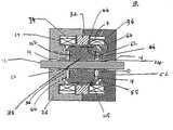
- FIG. 1shows a cross-sectioned view of a conventional force motor.
- a conventional force motorincludes a shaft 1 mounted in bearings 2 that are mounted in a housing 3 .
- An armature 4is mounted on the shaft.
- Two springs 5 and 6are mounted on the shaft with the armature located between the springs. The springs keep the armature in the neutral position when no net axial force is being exerted on the armature.
- the armature shaftis free to slide on the bearings in axial directions.
- a permanent magnet 7is located at the periphery of the armature.
- Two coils 8 and 9wound in the same direction are located on each side of the permanent magnet.
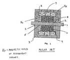
- the permanent magnetproduces a magnetic field B p .
- the coilsWhen energized, the coils produce a magnetic field B i . Since the coils are wound in the same direction the magnetic field B i produced by the coils is in the same direction as the magnetic field B p on one side of the permanent magnet and in the opposing direction on the other side of the permanent magnet.
- the resultant magnetic field on one side of the permanent magnetis B p +B i and on the other side of the permanent magnet is B p ⁇ B i . See FIG. 2.
- the electrical force produced on the armatureis proportional to the square of the magnetic field and can be calculated as follows.
- Iis the current supplied to the coils
- B pcan be assumed to be constant only when the armature is in the neutral position. As the armature moves away from the neutral position, B p changes. When the armature moves, B p on one side of the armature increases whereas B p on the other side of the armature decreases. This results in a dramatic increase in the net force on the armature.
- the forceis proportional to the stroke only within a small range of the stroke, for example 0.01 to 0.03 inches.
- U.S. Pat. No. 5,787,915describes a conventional force motor having a permanent magnet and coils. However, it does not teach any means of providing increased proportional stroke.
- U.S. Pat. No. 3,900,822(the '822 Patent) describes a conventional proportional solenoid with a conical pole piece on each side of the bobbin.
- the solenoidWhen the solenoid is energized, the armature is pulled to one side and enters into the conical pole piece.
- the conical pole pieceprovides a leakage flux path and thereby reduces the increase in the net force on the armature.
- the proportional solenoid similar to that of the '822 Patentrequires higher power input compared to the force motor of the present invention to produce the same amount of force on the armature.
- the force motor of the present inventionovercomes the aforesaid shortcomings of the prior art by controlling the local magnetic field through a uniquely designed mechanical configuration of the internal components.
- the mechanical configurationdivides the magnetic field in the force motor into three sections. In operation, as the armature moves in the axial direction towards the end of the stroke, the force exerted on the armature by a magnetic field in the first section increases exponentially. At the same time, the force exerted by the magnetic field in the third section either has a smaller increase compared to the first section, or decreases. As the armature moves towards the stop, the amount of magnetic flux in the second section increases.
- the direction of this magnetic fieldis perpendicular to the armature's direction of movement and therefore does not produce any force in the direction of the movement thereby reducing the total force on the armature.
- a housinghaving an internal wall, a cylindrical extension projecting from the internal wall working as a stop to limit the armature's movement, and a concave surface formed on the internal wall.
- An armature supported by the bearingsits in the housing.
- the armatureincludes a cylindrical portion connected to a conical section. The shape of the armature and the housing are such that they cooperate to produce a flat F-S curve for the force motor.
- FIG. 1is a cross-sectional view of a prior art force motor
- FIG. 2shows a magnetic field produced in the force motor of FIG. 1;
- FIG. 3is a cross-sectional view of the force motor of the present invention.
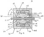
- FIG. 4is a cross-sectional view of another embodiment of the force motor of the present invention.
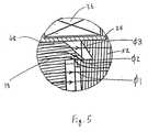
- FIG. 5is an enlarged view of cooperating mechanical structures of the force motor shown as detail E in FIG. 3;
- FIG. 6is a conceptual representation of the F-S curve for the three sections formed by the cooperating sections of FIG. 5;
- FIG. 7shows F-S curves for a conventional force motor of FIG. 1 having a greater slope and F-S curves for the force motor of FIG. 4 which are flat.
- FIG. 8shows F-S curves for the force motor of FIG. 3.
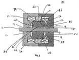
- FIG. 3shows a cross-sectional view of the force motor of the present invention.
- FIG. 4shows cross-sectional view of another embodiment of the force motor of the present invention.
- Force motor 10includes a shaft 12 which is slidably mounted in bearings 14 and 16 .
- Armature 18is firmly mounted on shaft 12 .
- Springs 22 and 24are mounted along shaft 12 , one on each side of armature 18 .
- the assembly of shaft 12 , bearings 14 and 16 , armature 18 and springs 22 and 24is mounted in a housing 26 .
- a bobbin 28is enclosed within housing 26 and is located at the periphery of armature 18 .
- Bobbin 28forms three compartments. In the center compartment is located a permanent magnet 32 .
- Bobbin 28prevents contaminants from magnet 32 from falling on the armature 18 .
- Coils 34 and 36are located one on each side of magnet 32 in the compartments formed by bobbin 28 .
- Armature 18is symmetric around the shaft 12 and includes a base 38 connected to a cylindrical portion 42 (see FIG. 3) which in turn is connected to a conical section 44 having cylindrical face 62 (formed by a counter-bore).
- base 38is connected to conical section 44 shaving a cylindrical face 62 which in turn is connected to cylindrical portion 42 .
- Armature 18 and housing 26are all made of a ferro-magnetic material that form a magnetic circuit.
- a stainless steel shim 46is mounted on cylindrical portion 42 of armature 18 . By varying the thickness of shim 46 , the travel of armature 18 along shaft 12 can be increased or decreased; a thicker shim 46 resulting in a shorter travel distance.
- Copper layer 48that is firmly attached to the armature 18 . Copper layer 48 induces back EMF to dampen the unexpected movement of the armature caused by vibration, shock, and acceleration.
- An internal wall 56 of housing 26is shaped to form a stop 52 .
- the shape of stop 52cooperates with the shape of armature 18 to provide control of the magnetic field in the area surrounding the cooperating shapes.
- Stop 52includes a cylindrical extension 54 which projects from internal wall 56 of housing 26 .
- Stop 52also has a concave conical surface 58 formed on wall 56 .
- Conical surface 58corresponds to the conical portion 44 on armature 18 .
- Cylindrical extension 54corresponds to the cylindrical portion 42 and in cooperation with steel shim 46 determines the maximum stroke length of armature 18 .
- Force motor 10 of the present inventionhas shaped armature 18 and stop 52 .
- the magnetic field between armature 18 and stop 52is divided into three sections.
- FIG. 5is the enlarged view of cooperating mechanical structures of armature 18 and stop 52 . Also shown in FIG. 5 are the three sections formed by the cooperating mechanical structures.
- FIG. 6shows a conceptual representation of the forces in the three sections formed by the cooperating mechanical structures.
- the first sectionis the magnetic field ⁇ 1 formed between cylindrical portion 42 and internal wall 56 .
- Thisis equivalent to a magnetic field inside a solenoid with flat-faced-armature.
- the characteristics of the force produced by this fieldare essentially exponential increase when the solenoid is pulled-in towards the stop (see curve A in FIG. 6).
- the second sectionis the magnetic field ⁇ 2 located between face 62 of conical section 44 on the armature 18 and the face 64 of cylindrical extension 54 . As a greater portion of face 62 slides along face 64 , ⁇ 2 increases. Since ⁇ 2 is perpendicular to the direction of motion of armature 18 , it does not produce any significant force in the direction of motion.
- Line B in FIG. 6is a conceptual representation of the force produced by ⁇ 2 , that is about zero all over the stroke length.
- the third sectionis the magnetic field ⁇ 3 located between conical section 44 on armature 18 and the conical face 58 on stop 52 . It is equivalent to a force in a conical-faced-armature solenoid. The characteristics of this force curve produced by ⁇ 3 is that it is flatter than that of the first section. (See curve C on FIG. 6 for a conceptual representation).
- the resultant force F fm exerted on armature 18 of force motor 10is the sum of the force represented by curve A′, B, and C′. i.e.
- a desired force—stroke characteristics curvecan be achieved. Adjustment of force—stroke characteristics may also be done by use of materials with different magnetic properties.
- a flat F-S curveadvantageously allows the use of springs with a smaller spring constant, to have wide range of control and more precise control.
- FIG. 7shows F-S curves for a conventional force motor such as shown in FIG. 1 and force motor 10 of the present invention as shown in FIG. 4 for comparison.
- FIG. 8shows the F-S curves for the embodiment of the force motor 10 shown in FIG. 3.
- the embodiments shown in FIG. 3 and FIG. 4have a flat F-S curve over the stroke length of 0.0 to 0.065 in. and 0.0 to 0.16 in., respectively while the conventional force motor only has proportional stroke of 0.0 to 0.025 in.
- the force motors used to obtain the curveshad the same external dimensions, used a similar magnet, used similar coils and had the same armature diameter. The only difference between the motors was the presence of cooperating mechanical structures as described previously in reference to force motor 10 .
- the F-S curves for the conventional force motorare the ones with greater slope and shorter stroke.
- the F-S curves for the force motor 10are very much flat over a greatly longer stroke, the proportional stroke length being (0.15 inches) six times the proportional stroke length (0.025 inches) for the conventional force motor.
- the substantially constant forceis between 0.2 and 2 lbs. with a variation of about 0.2 lbs. maximum for any curve.
- the substantially constant forceis 0.4 to 5.5 lbs. with a variation of about 1.5 lbs. for any one curve.
- the inventioncontrols the slope of the F-S curve even if the slope is not driven to zero. As shown in FIG. 8, there may be a slight slope.
- the local magnetic fieldmay be controlled be varying the shape and size or location of the mechanical configurations in a different manner than described here.
- the local magnetic field controlmay also be achieved by using different materials with different magnetic properties.
Landscapes
- Physics & Mathematics (AREA)
- Electromagnetism (AREA)
- Engineering & Computer Science (AREA)
- Power Engineering (AREA)
- Reciprocating, Oscillating Or Vibrating Motors (AREA)
- Iron Core Of Rotating Electric Machines (AREA)
- Motor Or Generator Frames (AREA)
- Electromagnets (AREA)
Abstract
Description
- 1. Field of the Invention[0001]
- This disclosure relates generally to a linear actuated force motor that requires low power input and provides a long proportional stroke. More particularly, this disclosure relates to a technique to control local magnetic field distribution so as to provide a long proportional stroke.[0002]
- 2. Description of the Related Art[0003]
- FIG. 1 shows a cross-sectioned view of a conventional force motor. A conventional force motor includes a[0004]
shaft 1 mounted inbearings 2 that are mounted in ahousing 3. Anarmature 4 is mounted on the shaft. Twosprings permanent magnet 7 is located at the periphery of the armature. Twocoils 8 and9, wound in the same direction are located on each side of the permanent magnet. - The permanent magnet produces a magnetic field B[0005]p. When energized, the coils produce a magnetic field Bi. Since the coils are wound in the same direction the magnetic field Biproduced by the coils is in the same direction as the magnetic field Bpon one side of the permanent magnet and in the opposing direction on the other side of the permanent magnet. Thus, the resultant magnetic field on one side of the permanent magnet is Bp+Biand on the other side of the permanent magnet is Bp−Bi. See FIG. 2. The electrical force produced on the armature is proportional to the square of the magnetic field and can be calculated as follows.
- F=KB2 Eqn. 1
- Where[0006]
- F=electrical force[0007]
- B=Magnetic flux density[0008]
- K=Constant[0009]
- For a proportional solenoid wherein a coil produces a magnetic field equal to Bi, the net force on the armature can be calculated using[0011]
equation 1 as follows: - Fps=KBi2 Eqn. 3
- Now if[0012]
- B[0013]p>Bi
- then[0014]
- 4B[0015]p>>Bi
- Therefore[0016]
- F[0017]fm>>Fps
- Thus, by using a permanent magnet, for a given level of coil energization (i.e. current), the force motor produces larger net force on the armature. Therefore, for a given force requirement the force motor can be operated with lower power input compared to the proportional solenoid. If B[0018]pis assumed to be constant in
equation 2, it is clear the net force is proportional to the magnetic field produced by the coils. - Ffm=CBi Eqn. 4
- where[0019]
- C=4KB[0020]p,
- assuming[0021]
- B[0022]p=constant
- Since[0023]
- B[0024]iis proportional to I
- where I is the current supplied to the coils,[0025]
- F[0026]fmis proportional to I
- i.e. the net force on the armature is proportional to the current supplied to the coils.[0027]
- However, B[0028]pcan be assumed to be constant only when the armature is in the neutral position. As the armature moves away from the neutral position, Bpchanges. When the armature moves, Bpon one side of the armature increases whereas Bpon the other side of the armature decreases. This results in a dramatic increase in the net force on the armature. Thus, in a conventional force motor, the force is proportional to the stroke only within a small range of the stroke, for example 0.01 to 0.03 inches.
- U.S. Pat. No. 5,787,915 describes a conventional force motor having a permanent magnet and coils. However, it does not teach any means of providing increased proportional stroke.[0029]
- U.S. Pat. No. 3,900,822 (the '822 Patent) describes a conventional proportional solenoid with a conical pole piece on each side of the bobbin. When the solenoid is energized, the armature is pulled to one side and enters into the conical pole piece. The conical pole piece provides a leakage flux path and thereby reduces the increase in the net force on the armature. The proportional solenoid similar to that of the '822 Patent requires higher power input compared to the force motor of the present invention to produce the same amount of force on the armature.[0030]
- The use of a conical pole piece as taught by the '822 Patent does not provide a substantial increase in proportional stroke. Additionally, when a conical pole piece is used, the proportionality and the constancy of the net force on the armature gets worse with increase in current (I) supplied to the coils or when the plunger position changes.[0031]
- None of the above mentioned patents teach a force motor with a long proportional stroke with a flat force versus stroke characteristic (F-S curve) and low power input.[0032]
- The force motor of the present invention overcomes the aforesaid shortcomings of the prior art by controlling the local magnetic field through a uniquely designed mechanical configuration of the internal components. The mechanical configuration divides the magnetic field in the force motor into three sections. In operation, as the armature moves in the axial direction towards the end of the stroke, the force exerted on the armature by a magnetic field in the first section increases exponentially. At the same time, the force exerted by the magnetic field in the third section either has a smaller increase compared to the first section, or decreases. As the armature moves towards the stop, the amount of magnetic flux in the second section increases. The direction of this magnetic field is perpendicular to the armature's direction of movement and therefore does not produce any force in the direction of the movement thereby reducing the total force on the armature. By adjusting the mechanical parameters associated with the three sections, the net axial force on the armature can be controlled, thereby providing, for a given power level, a flat force vs. stroke curve over a long stroke.[0033]
- It is an object of the present invention to provide a force motor with low power input to achieve a desired force with a flat F-S curve and long proportional stroke when compared to a conventional proportional solenoid. These and other objects are accomplished by providing a housing and an armature movable along an axial direction in the housing wherein the shape of the armature and the housing cooperate to produce a flat F-S curve for the force motor. The invention further contemplates a method of controlling the magnetic field in a force motor to obtain a flat F-S curve by forming a first section having a first magnetic field that produces a force on the armature that increases as the armature approaches the housing and forming a second section and a third section in the force motor. The force on the armature due to the a second magnetic field in the second section and a third magnetic field in the third section, as the armature approaches the housing, counter balances the force on the armature produced by the first magnetic field in the first section to produce the flat F-S curve.[0034]
- Also provided is a housing having an internal wall, a cylindrical extension projecting from the internal wall working as a stop to limit the armature's movement, and a concave surface formed on the internal wall. An armature supported by the bearing sits in the housing. The armature includes a cylindrical portion connected to a conical section. The shape of the armature and the housing are such that they cooperate to produce a flat F-S curve for the force motor.[0035]
- Further features and advantages will appear more clearly on a reading of the detailed description, which is given below by way of example only and with reference to the accompanying drawings wherein corresponding reference characters on different drawings indicate corresponding parts.[0036]
- FIG. 1 is a cross-sectional view of a prior art force motor;[0037]
- FIG. 2 shows a magnetic field produced in the force motor of FIG. 1;[0038]
- FIG. 3 is a cross-sectional view of the force motor of the present invention;[0039]
- FIG. 4 is a cross-sectional view of another embodiment of the force motor of the present invention;[0040]
- FIG. 5 is an enlarged view of cooperating mechanical structures of the force motor shown as detail E in FIG. 3;[0041]
- FIG. 6 is a conceptual representation of the F-S curve for the three sections formed by the cooperating sections of FIG. 5;[0042]
- FIG. 7 shows F-S curves for a conventional force motor of FIG. 1 having a greater slope and F-S curves for the force motor of FIG. 4 which are flat.[0043]
- FIG. 8 shows F-S curves for the force motor of FIG. 3.[0044]
- FIG. 3 shows a cross-sectional view of the force motor of the present invention. FIG. 4 shows cross-sectional view of another embodiment of the force motor of the present invention.[0045]
Force motor 10 includes ashaft 12 which is slidably mounted inbearings Armature 18 is firmly mounted onshaft 12.Springs shaft 12, one on each side ofarmature 18. The assembly ofshaft 12,bearings armature 18 and springs22 and24 is mounted in ahousing 26. Abobbin 28 is enclosed withinhousing 26 and is located at the periphery ofarmature 18.Bobbin 28 forms three compartments. In the center compartment is located apermanent magnet 32.Bobbin 28 prevents contaminants frommagnet 32 from falling on thearmature 18.Coils magnet 32 in the compartments formed bybobbin 28. - [0046]
Armature 18 is symmetric around theshaft 12 and includes a base38 connected to a cylindrical portion42 (see FIG. 3) which in turn is connected to aconical section 44 having cylindrical face62 (formed by a counter-bore). In the embodiment of FIG. 4base 38 is connected toconical section 44 shaving acylindrical face 62 which in turn is connected tocylindrical portion 42.Armature 18 andhousing 26 are all made of a ferro-magnetic material that form a magnetic circuit. Astainless steel shim 46 is mounted oncylindrical portion 42 ofarmature 18. By varying the thickness ofshim 46, the travel ofarmature 18 alongshaft 12 can be increased or decreased; athicker shim 46 resulting in a shorter travel distance. Between bobbin28 andarmature 18, along the periphery ofarmature 18, is located acylindrical copper layer 48 that is firmly attached to thearmature 18.Copper layer 48 induces back EMF to dampen the unexpected movement of the armature caused by vibration, shock, and acceleration. - An[0047]
internal wall 56 ofhousing 26 is shaped to form astop 52. The shape ofstop 52 cooperates with the shape ofarmature 18 to provide control of the magnetic field in the area surrounding the cooperating shapes.Stop 52 includes acylindrical extension 54 which projects frominternal wall 56 ofhousing 26.Stop 52 also has a concaveconical surface 58 formed onwall 56.Conical surface 58 corresponds to theconical portion 44 onarmature 18.Cylindrical extension 54 corresponds to thecylindrical portion 42 and in cooperation withsteel shim 46 determines the maximum stroke length ofarmature 18. - When coils[0048]34 and36 are energized by current I, magnetic field Biis produced. Magnetic field Biinteracts with magnetic field Bpas described previously in reference to the conventional force motor. The action of these two magnetic fields combined produces a net force Ffmon
armature 18. However, as compared to the conventional force motor, the force Ffmfor a given I remains constant over a longer stroke length for the reasons explained below. - [0049]
Force motor 10 of the present invention has shapedarmature 18 and stop52. The magnetic field betweenarmature 18 and stop52 is divided into three sections. FIG. 5 is the enlarged view of cooperating mechanical structures ofarmature 18 and stop52. Also shown in FIG. 5 are the three sections formed by the cooperating mechanical structures. FIG. 6 shows a conceptual representation of the forces in the three sections formed by the cooperating mechanical structures. - The first section is the magnetic field Φ[0050]1formed between
cylindrical portion 42 andinternal wall 56. This is equivalent to a magnetic field inside a solenoid with flat-faced-armature. The characteristics of the force produced by this field are essentially exponential increase when the solenoid is pulled-in towards the stop (see curve A in FIG. 6). - The second section is the magnetic field Φ[0051]2located between
face 62 ofconical section 44 on thearmature 18 and theface 64 ofcylindrical extension 54. As a greater portion offace 62 slides alongface 64, Φ2increases. Since Φ2is perpendicular to the direction of motion ofarmature 18, it does not produce any significant force in the direction of motion. Line B in FIG. 6 is a conceptual representation of the force produced by Φ2, that is about zero all over the stroke length. - The third section is the magnetic field Φ[0052]3located between
conical section 44 onarmature 18 and theconical face 58 onstop 52. It is equivalent to a force in a conical-faced-armature solenoid. The characteristics of this force curve produced by Φ3is that it is flatter than that of the first section. (See curve C on FIG. 6 for a conceptual representation). - When the armature is pulled-in, the second section of magnetic field Φ[0053]2takes away the magnetic flux from the first section and the third section. Therefore, the force produced by Φ1and Φ3is actually reduced due to the increase of leakage flux in the second section, and the force-stoke curves produced by the magnetic field of the first section and the third section drop down (see curve A′ and C′ on FIG. 6).
- The resultant force F[0054]fmexerted on
armature 18 offorce motor 10 is the sum of the force represented by curve A′, B, and C′. i.e. - Ffm=FΦ1+FΦ2+FΦ3 Eqn. 5
- Thus, by adjusting the cooperating mechanical structures on[0055]
armature 18 and stop52, for example, by varying the shape, size and angles of cooperating mechanical elements, a desired force—stroke characteristics curve can be achieved. Adjustment of force—stroke characteristics may also be done by use of materials with different magnetic properties. A flat F-S curve advantageously allows the use of springs with a smaller spring constant, to have wide range of control and more precise control. - FIG. 7 shows F-S curves for a conventional force motor such as shown in FIG. 1 and force[0056]
motor 10 of the present invention as shown in FIG. 4 for comparison. FIG. 8 shows the F-S curves for the embodiment of theforce motor 10 shown in FIG. 3. The embodiments shown in FIG. 3 and FIG. 4 have a flat F-S curve over the stroke length of 0.0 to 0.065 in. and 0.0 to 0.16 in., respectively while the conventional force motor only has proportional stroke of 0.0 to 0.025 in. The force motors used to obtain the curves had the same external dimensions, used a similar magnet, used similar coils and had the same armature diameter. The only difference between the motors was the presence of cooperating mechanical structures as described previously in reference to forcemotor 10. The F-S curves for the conventional force motor are the ones with greater slope and shorter stroke. On the other hand, the F-S curves for theforce motor 10 are very much flat over a greatly longer stroke, the proportional stroke length being (0.15 inches) six times the proportional stroke length (0.025 inches) for the conventional force motor. In FIG. 7, the substantially constant force is between 0.2 and 2 lbs. with a variation of about 0.2 lbs. maximum for any curve. In FIG. 8, the substantially constant force is 0.4 to 5.5 lbs. with a variation of about 1.5 lbs. for any one curve. - The invention controls the slope of the F-S curve even if the slope is not driven to zero. As shown in FIG. 8, there may be a slight slope.[0057]
- While a preferred embodiment of the invention has been described, various modifications will be apparent to one skilled in the art in light of this disclosure and are intended to fall within the scope of the appended claims. For example, the local magnetic field may be controlled be varying the shape and size or location of the mechanical configurations in a different manner than described here. The local magnetic field control may also be achieved by using different materials with different magnetic properties.[0058]

Claims (16)
Priority Applications (7)
| Application Number | Priority Date | Filing Date | Title |
|---|---|---|---|
| US10/159,217US7078833B2 (en) | 2002-05-31 | 2002-05-31 | Force motor with increased proportional stroke |
| TW092114755ATW200402183A (en) | 2002-05-31 | 2003-05-30 | Force motor with increased proportional stroke |
| AU2003234678AAU2003234678A1 (en) | 2002-05-31 | 2003-05-30 | Force motor with increased proportional stroke |
| PCT/US2003/016813WO2003102979A1 (en) | 2002-05-31 | 2003-05-30 | Force motor with increased proportional stroke |
| CNB038125404ACN100390907C (en) | 2002-05-31 | 2003-05-30 | Force motor with increased proportional stroke |
| JP2004509973AJP2005528874A (en) | 2002-05-31 | 2003-05-30 | Force motor with increased proportional stroke |
| EP03729180AEP1520280A1 (en) | 2002-05-31 | 2003-05-30 | Force motor with increased proportional stroke |
Applications Claiming Priority (1)
| Application Number | Priority Date | Filing Date | Title |
|---|---|---|---|
| US10/159,217US7078833B2 (en) | 2002-05-31 | 2002-05-31 | Force motor with increased proportional stroke |
Publications (2)
| Publication Number | Publication Date |
|---|---|
| US20030222534A1true US20030222534A1 (en) | 2003-12-04 |
| US7078833B2 US7078833B2 (en) | 2006-07-18 |
Family
ID=29582850
Family Applications (1)
| Application Number | Title | Priority Date | Filing Date |
|---|---|---|---|
| US10/159,217Expired - Fee RelatedUS7078833B2 (en) | 2002-05-31 | 2002-05-31 | Force motor with increased proportional stroke |
Country Status (7)
| Country | Link |
|---|---|
| US (1) | US7078833B2 (en) |
| EP (1) | EP1520280A1 (en) |
| JP (1) | JP2005528874A (en) |
| CN (1) | CN100390907C (en) |
| AU (1) | AU2003234678A1 (en) |
| TW (1) | TW200402183A (en) |
| WO (1) | WO2003102979A1 (en) |
Cited By (6)
| Publication number | Priority date | Publication date | Assignee | Title |
|---|---|---|---|---|
| US20050279415A1 (en)* | 2004-06-14 | 2005-12-22 | Minebea Company, Ltd. | Servo valve with miniature embedded force motor with stiffened armature |
| US20090146509A1 (en)* | 2005-09-08 | 2009-06-11 | Namiki Seimitsu Houseki Kabusikikaisha | Vibration actuator |
| TWI382879B (en)* | 2004-09-09 | 2013-01-21 | Namiki Precision Jewel Co Ltd | Flat vibrating drive |
| US11239736B1 (en)* | 2017-08-14 | 2022-02-01 | The Government Of The United States Of America, As Represented By The Secretary Of The Navy | Linear electromagnetic actuator |
| US11410809B2 (en)* | 2017-12-28 | 2022-08-09 | Hyosung Heavy Industries Corporation | High-speed solenoid |
| WO2022229396A1 (en)* | 2021-04-29 | 2022-11-03 | Samson Aktiengesellschaft | Electromagnetic drive for a 3/2-way valve, for example, and 3/2-way valve |
Families Citing this family (13)
| Publication number | Priority date | Publication date | Assignee | Title |
|---|---|---|---|---|
| CN1593001A (en)* | 2001-11-23 | 2005-03-09 | 伊斯姆公司 | Method and devices for driving a body |
| US7209020B2 (en)* | 2003-06-09 | 2007-04-24 | Borgwarner Inc. | Variable force solenoid |
| DE102004009251B4 (en)* | 2004-02-26 | 2006-05-24 | Hess Maschinenfabrik Gmbh & Co. Kg | Vibrator for applying an object in a predetermined direction and apparatus for producing concrete blocks |
| JP5003992B2 (en)* | 2005-12-20 | 2012-08-22 | 株式会社安川電機 | Cylindrical linear motor |
| US9325232B1 (en) | 2010-07-22 | 2016-04-26 | Linear Labs, Inc. | Method and apparatus for power generation |
| US8922070B2 (en)* | 2010-10-22 | 2014-12-30 | Linear Labs, Inc. | Magnetic motor |
| JP5939534B2 (en)* | 2012-01-30 | 2016-06-22 | 新電元メカトロニクス株式会社 | solenoid |
| DE102012012779A1 (en)* | 2012-06-25 | 2014-03-27 | Thomas Magnete Gmbh | Electromagnetic pump |
| US9219962B2 (en) | 2012-09-03 | 2015-12-22 | Linear Labs, Inc. | Transducer and method of operation |
| WO2014036567A1 (en) | 2012-09-03 | 2014-03-06 | Linear Labs, Inc. | An improved transducer and method of operation |
| CN103971999A (en)* | 2013-02-01 | 2014-08-06 | 西安圣华农业科技股份有限公司 | Long-stroke low-temperature-rise double-coil electromagnet |
| DE102019204839B4 (en)* | 2019-03-01 | 2025-02-27 | Festo Se & Co. Kg | Electromagnetic drive device and proportional solenoid valve equipped with it |
| US11894187B2 (en)* | 2019-08-22 | 2024-02-06 | Husco Automotive Holdings Llc | Systems and methods for multi-stable solenoid |
Citations (15)
| Publication number | Priority date | Publication date | Assignee | Title |
|---|---|---|---|---|
| US3381250A (en)* | 1966-06-27 | 1968-04-30 | Sperry Rand Corp | Electromagnetic device |
| US3805204A (en)* | 1972-04-21 | 1974-04-16 | Polaroid Corp | Tractive electromagnetic device |
| US3870931A (en)* | 1974-02-04 | 1975-03-11 | Sun Chemical Corp | Solenoid servomechanism |
| US3900822A (en)* | 1974-03-12 | 1975-08-19 | Ledex Inc | Proportional solenoid |
| US3970891A (en)* | 1974-03-01 | 1976-07-20 | Siemens Aktiengesellschaft | Electron collector for an electron beam tube |
| US4097833A (en)* | 1976-02-09 | 1978-06-27 | Ledex, Inc. | Electromagnetic actuator |
| US4144514A (en)* | 1976-11-03 | 1979-03-13 | General Electric Company | Linear motion, electromagnetic force motor |
| US4651118A (en)* | 1984-11-07 | 1987-03-17 | Zeuner Kenneth W | Proportional solenoid |
| USRE32783E (en)* | 1983-12-23 | 1988-11-15 | G. W. Lisk Company, Inc. | Solenoid construction and method for making the same |
| US4954799A (en)* | 1989-06-02 | 1990-09-04 | Puritan-Bennett Corporation | Proportional electropneumatic solenoid-controlled valve |
| US5108070A (en)* | 1990-03-28 | 1992-04-28 | Mitsubishi Denki Kabushiki Kaisha | Flow control solenoid valve apparatus |
| US5407174A (en)* | 1990-08-31 | 1995-04-18 | Puritan-Bennett Corporation | Proportional electropneumatic solenoid-controlled valve |
| US5787915A (en)* | 1997-01-21 | 1998-08-04 | J. Otto Byers & Associates | Servo positioning system |
| US6047672A (en)* | 1998-03-04 | 2000-04-11 | Aisan Kogyo Kabushiki Kaisha | Engine valve-driving electromagnetic valve |
| US6495821B1 (en)* | 1999-02-17 | 2002-12-17 | The Chamberlain Group, Inc. | Method and apparatus for determining a position of a movable barrier |
Family Cites Families (5)
| Publication number | Priority date | Publication date | Assignee | Title |
|---|---|---|---|---|
| US1954799A (en)* | 1933-04-17 | 1934-04-17 | New Jersey Zinc Co | Paper-making |
| DE847465C (en) | 1940-12-05 | 1952-08-25 | Wilhelm Binder Fa | Pot-shaped electromagnet with an armature counterpart, which has a cavity |
| US3970981A (en) | 1975-05-08 | 1976-07-20 | Ledex, Inc. | Electric solenoid structure |
| US4604600A (en)* | 1983-12-23 | 1986-08-05 | G. W. Lisk Company, Inc. | Solenoid construction and method for making the same |
| WO1999023674A1 (en)* | 1997-11-03 | 1999-05-14 | Diesel Engine Retarders, Inc. | Cascading electromagnetic armature |
- 2002
- 2002-05-31USUS10/159,217patent/US7078833B2/ennot_activeExpired - Fee Related
- 2003
- 2003-05-30WOPCT/US2003/016813patent/WO2003102979A1/enactiveApplication Filing
- 2003-05-30JPJP2004509973Apatent/JP2005528874A/ennot_activeWithdrawn
- 2003-05-30TWTW092114755Apatent/TW200402183A/enunknown
- 2003-05-30EPEP03729180Apatent/EP1520280A1/ennot_activeWithdrawn
- 2003-05-30CNCNB038125404Apatent/CN100390907C/ennot_activeExpired - Fee Related
- 2003-05-30AUAU2003234678Apatent/AU2003234678A1/ennot_activeAbandoned
Patent Citations (15)
| Publication number | Priority date | Publication date | Assignee | Title |
|---|---|---|---|---|
| US3381250A (en)* | 1966-06-27 | 1968-04-30 | Sperry Rand Corp | Electromagnetic device |
| US3805204A (en)* | 1972-04-21 | 1974-04-16 | Polaroid Corp | Tractive electromagnetic device |
| US3870931A (en)* | 1974-02-04 | 1975-03-11 | Sun Chemical Corp | Solenoid servomechanism |
| US3970891A (en)* | 1974-03-01 | 1976-07-20 | Siemens Aktiengesellschaft | Electron collector for an electron beam tube |
| US3900822A (en)* | 1974-03-12 | 1975-08-19 | Ledex Inc | Proportional solenoid |
| US4097833A (en)* | 1976-02-09 | 1978-06-27 | Ledex, Inc. | Electromagnetic actuator |
| US4144514A (en)* | 1976-11-03 | 1979-03-13 | General Electric Company | Linear motion, electromagnetic force motor |
| USRE32783E (en)* | 1983-12-23 | 1988-11-15 | G. W. Lisk Company, Inc. | Solenoid construction and method for making the same |
| US4651118A (en)* | 1984-11-07 | 1987-03-17 | Zeuner Kenneth W | Proportional solenoid |
| US4954799A (en)* | 1989-06-02 | 1990-09-04 | Puritan-Bennett Corporation | Proportional electropneumatic solenoid-controlled valve |
| US5108070A (en)* | 1990-03-28 | 1992-04-28 | Mitsubishi Denki Kabushiki Kaisha | Flow control solenoid valve apparatus |
| US5407174A (en)* | 1990-08-31 | 1995-04-18 | Puritan-Bennett Corporation | Proportional electropneumatic solenoid-controlled valve |
| US5787915A (en)* | 1997-01-21 | 1998-08-04 | J. Otto Byers & Associates | Servo positioning system |
| US6047672A (en)* | 1998-03-04 | 2000-04-11 | Aisan Kogyo Kabushiki Kaisha | Engine valve-driving electromagnetic valve |
| US6495821B1 (en)* | 1999-02-17 | 2002-12-17 | The Chamberlain Group, Inc. | Method and apparatus for determining a position of a movable barrier |
Cited By (8)
| Publication number | Priority date | Publication date | Assignee | Title |
|---|---|---|---|---|
| US20050279415A1 (en)* | 2004-06-14 | 2005-12-22 | Minebea Company, Ltd. | Servo valve with miniature embedded force motor with stiffened armature |
| WO2005124206A3 (en)* | 2004-06-14 | 2007-02-01 | Minebea Co Ltd | Servo valve with miniature embedded force motor with stiffened armature |
| US7455075B2 (en)* | 2004-06-14 | 2008-11-25 | Minebea Co., Ltd. | Servo valve with miniature embedded force motor with stiffened armature |
| TWI382879B (en)* | 2004-09-09 | 2013-01-21 | Namiki Precision Jewel Co Ltd | Flat vibrating drive |
| US20090146509A1 (en)* | 2005-09-08 | 2009-06-11 | Namiki Seimitsu Houseki Kabusikikaisha | Vibration actuator |
| US11239736B1 (en)* | 2017-08-14 | 2022-02-01 | The Government Of The United States Of America, As Represented By The Secretary Of The Navy | Linear electromagnetic actuator |
| US11410809B2 (en)* | 2017-12-28 | 2022-08-09 | Hyosung Heavy Industries Corporation | High-speed solenoid |
| WO2022229396A1 (en)* | 2021-04-29 | 2022-11-03 | Samson Aktiengesellschaft | Electromagnetic drive for a 3/2-way valve, for example, and 3/2-way valve |
Also Published As
| Publication number | Publication date |
|---|---|
| US7078833B2 (en) | 2006-07-18 |
| CN1656576A (en) | 2005-08-17 |
| WO2003102979A1 (en) | 2003-12-11 |
| JP2005528874A (en) | 2005-09-22 |
| AU2003234678A1 (en) | 2003-12-19 |
| CN100390907C (en) | 2008-05-28 |
| TW200402183A (en) | 2004-02-01 |
| EP1520280A1 (en) | 2005-04-06 |
| WO2003102979B1 (en) | 2004-07-22 |
Similar Documents
| Publication | Publication Date | Title |
|---|---|---|
| US20030222534A1 (en) | Force motor with increased proportional stroke | |
| JP3437126B2 (en) | Linear actuator and manufacturing method thereof | |
| US4633209A (en) | DC electromagnet, in particular for an electric switching apparatus | |
| JP4571189B2 (en) | Long proportional stroke force motor | |
| EP0740096A2 (en) | Valve actuator | |
| US6867511B2 (en) | Linear oscillatory actuator | |
| US20100066180A1 (en) | Linear drive device provided with an armature body having a magnet carrier | |
| US20140028420A1 (en) | Moving Magnet Actuator with Counter-Cogging End-Ring and Asymmetrical Armature Stroke | |
| US6028499A (en) | Monophase, short travel, electromagnetic actuator having a good electric power/force ratio | |
| US4835503A (en) | Linear proportional solenoid | |
| KR900000430B1 (en) | Electromagnetic actuator | |
| US4181866A (en) | Permanent magnet with reduced thickness at the pole areas for small size d-c motors | |
| US6198179B1 (en) | Linear actuator | |
| US4717900A (en) | Low profile electromagnetic linear motion device | |
| JPS6141123B2 (en) | ||
| JPH11162732A (en) | Electromagnetic solenoid | |
| JP2002051531A (en) | Movable magnet type actuator | |
| JPH075611Y2 (en) | Electromagnetic device | |
| JPH0518444B2 (en) | ||
| WO2014165790A1 (en) | Self-centering electromagnetic transducers | |
| JPH0119587Y2 (en) | ||
| JPH073602Y2 (en) | Electromagnetic actuator | |
| JPS6020773Y2 (en) | Actuator for door lock | |
| JPS5926791Y2 (en) | linear motor | |
| JP2701482B2 (en) | Solenoid device |
Legal Events
| Date | Code | Title | Description |
|---|---|---|---|
| AS | Assignment | Owner name:NMB (USA), INC., CALIFORNIA Free format text:ASSIGNMENT OF ASSIGNORS INTEREST;ASSIGNOR:XU, YAO HUI;REEL/FRAME:013230/0345 Effective date:20020713 | |
| AS | Assignment | Owner name:MINEBEA ELECTRONICS CO., LTD., JAPAN Free format text:ASSIGNMENT OF ASSIGNORS INTEREST;ASSIGNOR:NMB (U.S.A.), INC.;REEL/FRAME:013249/0706 Effective date:20021007 | |
| AS | Assignment | Owner name:MINEBEA CO., LTD., JAPAN Free format text:ASSIGNMENT OF ASSIGNORS INTEREST;ASSIGNOR:MINEBEA ELECTRONICS CO., LTD.;REEL/FRAME:013285/0758 Effective date:20021002 | |
| FPAY | Fee payment | Year of fee payment:4 | |
| FEPP | Fee payment procedure | Free format text:PAYOR NUMBER ASSIGNED (ORIGINAL EVENT CODE: ASPN); ENTITY STATUS OF PATENT OWNER: LARGE ENTITY | |
| FPAY | Fee payment | Year of fee payment:8 | |
| FEPP | Fee payment procedure | Free format text:MAINTENANCE FEE REMINDER MAILED (ORIGINAL EVENT CODE: REM.) | |
| LAPS | Lapse for failure to pay maintenance fees | Free format text:PATENT EXPIRED FOR FAILURE TO PAY MAINTENANCE FEES (ORIGINAL EVENT CODE: EXP.) | |
| STCH | Information on status: patent discontinuation | Free format text:PATENT EXPIRED DUE TO NONPAYMENT OF MAINTENANCE FEES UNDER 37 CFR 1.362 | |
| FP | Lapsed due to failure to pay maintenance fee | Effective date:20180718 |