US20030199874A1 - Dynamic lordotic guard with movable extensions for creating an implantation space posteriorly in the lumbar spine and method for use thereof - Google Patents
Dynamic lordotic guard with movable extensions for creating an implantation space posteriorly in the lumbar spine and method for use thereofDownload PDFInfo
- Publication number
- US20030199874A1 US20030199874A1US10/125,847US12584702AUS2003199874A1US 20030199874 A1US20030199874 A1US 20030199874A1US 12584702 AUS12584702 AUS 12584702AUS 2003199874 A1US2003199874 A1US 2003199874A1
- Authority
- US
- United States
- Prior art keywords
- guard
- bone
- vertebral bodies
- portions
- adjacent vertebral
- Prior art date
- Legal status (The legal status is an assumption and is not a legal conclusion. Google has not performed a legal analysis and makes no representation as to the accuracy of the status listed.)
- Granted
Links
- 238000002513implantationMethods0.000titleclaimsabstractdescription55
- 238000000034methodMethods0.000titleabstractdescription36
- 230000001045lordotic effectEffects0.000titleabstractdescription6
- 210000004705lumbosacral regionAnatomy0.000titledescription6
- 239000007943implantSubstances0.000claimsabstractdescription116
- 210000000988bone and boneAnatomy0.000claimsabstractdescription87
- 230000000149penetrating effectEffects0.000claimsdescription75
- 238000005520cutting processMethods0.000claimsdescription53
- 238000003780insertionMethods0.000claimsdescription53
- 230000037431insertionEffects0.000claimsdescription53
- 239000000463materialSubstances0.000claimsdescription25
- 230000001737promoting effectEffects0.000claimsdescription21
- 230000008468bone growthEffects0.000claimsdescription18
- 239000000126substanceSubstances0.000claimsdescription17
- 238000001356surgical procedureMethods0.000claimsdescription15
- 108090000623proteins and genesProteins0.000claimsdescription11
- 102000007350Bone Morphogenetic ProteinsHuman genes0.000claimsdescription7
- 108010007726Bone Morphogenetic ProteinsProteins0.000claimsdescription7
- 229910052588hydroxylapatiteInorganic materials0.000claimsdescription7
- 230000033001locomotionEffects0.000claimsdescription7
- 238000004519manufacturing processMethods0.000claimsdescription7
- XYJRXVWERLGGKC-UHFFFAOYSA-Dpentacalcium;hydroxide;triphosphateChemical compound[OH-].[Ca+2].[Ca+2].[Ca+2].[Ca+2].[Ca+2].[O-]P([O-])([O-])=O.[O-]P([O-])([O-])=O.[O-]P([O-])([O-])=OXYJRXVWERLGGKC-UHFFFAOYSA-D0.000claimsdescription7
- 210000002805bone matrixAnatomy0.000claimsdescription6
- 229940112869bone morphogenetic proteinDrugs0.000claimsdescription5
- 229920003023plasticPolymers0.000claimsdescription5
- 239000004033plasticSubstances0.000claimsdescription5
- 230000036573scar formationEffects0.000claimsdescription5
- 102000004169proteins and genesHuman genes0.000claimsdescription4
- 241000283984RodentiaSpecies0.000claimsdescription3
- RTAQQCXQSZGOHL-UHFFFAOYSA-NTitaniumChemical compound[Ti]RTAQQCXQSZGOHL-UHFFFAOYSA-N0.000claimsdescription3
- 230000000845anti-microbial effectEffects0.000claimsdescription3
- 239000004599antimicrobialSubstances0.000claimsdescription3
- 239000000919ceramicSubstances0.000claimsdescription3
- 229910052751metalInorganic materials0.000claimsdescription3
- 239000002184metalSubstances0.000claimsdescription3
- 239000011148porous materialSubstances0.000claimsdescription3
- 229910052719titaniumInorganic materials0.000claimsdescription3
- 239000010936titaniumSubstances0.000claimsdescription3
- 230000004927fusionEffects0.000description23
- 208000007623LordosisDiseases0.000description7
- 238000005553drillingMethods0.000description6
- 238000007373indentationMethods0.000description5
- 230000008901benefitEffects0.000description4
- 230000001939inductive effectEffects0.000description3
- 230000002792vascularEffects0.000description3
- 150000001875compoundsChemical class0.000description2
- 230000001054cortical effectEffects0.000description2
- 230000002262irrigationEffects0.000description2
- 238000003973irrigationMethods0.000description2
- 238000003801millingMethods0.000description2
- 230000000087stabilizing effectEffects0.000description2
- 229910045601alloyInorganic materials0.000description1
- 239000000956alloySubstances0.000description1
- 230000003466anti-cipated effectEffects0.000description1
- 230000015572biosynthetic processEffects0.000description1
- 239000008280bloodSubstances0.000description1
- 210000004369bloodAnatomy0.000description1
- -1but not limited toSubstances0.000description1
- 210000000845cartilageAnatomy0.000description1
- 239000002131composite materialSubstances0.000description1
- 230000012010growthEffects0.000description1
- 230000002401inhibitory effectEffects0.000description1
- 238000002684laminectomyMethods0.000description1
- 238000012986modificationMethods0.000description1
- 230000004048modificationEffects0.000description1
- 210000005036nerveAnatomy0.000description1
- 230000001537neural effectEffects0.000description1
- 230000000926neurological effectEffects0.000description1
- 230000011164ossificationEffects0.000description1
- 238000002360preparation methodMethods0.000description1
- 238000002271resectionMethods0.000description1
- 125000006850spacer groupChemical group0.000description1
- 238000006467substitution reactionMethods0.000description1
Images


Classifications
- A—HUMAN NECESSITIES
- A61—MEDICAL OR VETERINARY SCIENCE; HYGIENE
- A61F—FILTERS IMPLANTABLE INTO BLOOD VESSELS; PROSTHESES; DEVICES PROVIDING PATENCY TO, OR PREVENTING COLLAPSING OF, TUBULAR STRUCTURES OF THE BODY, e.g. STENTS; ORTHOPAEDIC, NURSING OR CONTRACEPTIVE DEVICES; FOMENTATION; TREATMENT OR PROTECTION OF EYES OR EARS; BANDAGES, DRESSINGS OR ABSORBENT PADS; FIRST-AID KITS
- A61F2/00—Filters implantable into blood vessels; Prostheses, i.e. artificial substitutes or replacements for parts of the body; Appliances for connecting them with the body; Devices providing patency to, or preventing collapsing of, tubular structures of the body, e.g. stents
- A61F2/02—Prostheses implantable into the body
- A61F2/30—Joints
- A61F2/46—Special tools for implanting artificial joints
- A61F2/4603—Special tools for implanting artificial joints for insertion or extraction of endoprosthetic joints or of accessories thereof
- A61F2/4611—Special tools for implanting artificial joints for insertion or extraction of endoprosthetic joints or of accessories thereof of spinal prostheses
- A—HUMAN NECESSITIES
- A61—MEDICAL OR VETERINARY SCIENCE; HYGIENE
- A61B—DIAGNOSIS; SURGERY; IDENTIFICATION
- A61B17/00—Surgical instruments, devices or methods
- A61B17/02—Surgical instruments, devices or methods for holding wounds open, e.g. retractors; Tractors
- A61B17/025—Joint distractors
- A—HUMAN NECESSITIES
- A61—MEDICAL OR VETERINARY SCIENCE; HYGIENE
- A61B—DIAGNOSIS; SURGERY; IDENTIFICATION
- A61B17/00—Surgical instruments, devices or methods
- A61B17/14—Surgical saws
- A—HUMAN NECESSITIES
- A61—MEDICAL OR VETERINARY SCIENCE; HYGIENE
- A61B—DIAGNOSIS; SURGERY; IDENTIFICATION
- A61B17/00—Surgical instruments, devices or methods
- A61B17/14—Surgical saws
- A61B17/15—Guides therefor
- A—HUMAN NECESSITIES
- A61—MEDICAL OR VETERINARY SCIENCE; HYGIENE
- A61B—DIAGNOSIS; SURGERY; IDENTIFICATION
- A61B17/00—Surgical instruments, devices or methods
- A61B17/16—Instruments for performing osteoclasis; Drills or chisels for bones; Trepans
- A—HUMAN NECESSITIES
- A61—MEDICAL OR VETERINARY SCIENCE; HYGIENE
- A61B—DIAGNOSIS; SURGERY; IDENTIFICATION
- A61B17/00—Surgical instruments, devices or methods
- A61B17/16—Instruments for performing osteoclasis; Drills or chisels for bones; Trepans
- A61B17/1613—Component parts
- A61B17/1615—Drill bits, i.e. rotating tools extending from a handpiece to contact the worked material
- A—HUMAN NECESSITIES
- A61—MEDICAL OR VETERINARY SCIENCE; HYGIENE
- A61B—DIAGNOSIS; SURGERY; IDENTIFICATION
- A61B17/00—Surgical instruments, devices or methods
- A61B17/16—Instruments for performing osteoclasis; Drills or chisels for bones; Trepans
- A61B17/1662—Instruments for performing osteoclasis; Drills or chisels for bones; Trepans for particular parts of the body
- A61B17/1671—Instruments for performing osteoclasis; Drills or chisels for bones; Trepans for particular parts of the body for the spine
- A—HUMAN NECESSITIES
- A61—MEDICAL OR VETERINARY SCIENCE; HYGIENE
- A61B—DIAGNOSIS; SURGERY; IDENTIFICATION
- A61B17/00—Surgical instruments, devices or methods
- A61B17/16—Instruments for performing osteoclasis; Drills or chisels for bones; Trepans
- A61B17/17—Guides or aligning means for drills, mills, pins or wires
- A61B17/1703—Guides or aligning means for drills, mills, pins or wires using imaging means, e.g. by X-rays
- A—HUMAN NECESSITIES
- A61—MEDICAL OR VETERINARY SCIENCE; HYGIENE
- A61B—DIAGNOSIS; SURGERY; IDENTIFICATION
- A61B17/00—Surgical instruments, devices or methods
- A61B17/16—Instruments for performing osteoclasis; Drills or chisels for bones; Trepans
- A61B17/17—Guides or aligning means for drills, mills, pins or wires
- A61B17/1739—Guides or aligning means for drills, mills, pins or wires specially adapted for particular parts of the body
- A61B17/1757—Guides or aligning means for drills, mills, pins or wires specially adapted for particular parts of the body for the spine
- A—HUMAN NECESSITIES
- A61—MEDICAL OR VETERINARY SCIENCE; HYGIENE
- A61B—DIAGNOSIS; SURGERY; IDENTIFICATION
- A61B17/00—Surgical instruments, devices or methods
- A61B17/32—Surgical cutting instruments
- A61B17/320016—Endoscopic cutting instruments, e.g. arthroscopes, resectoscopes
- A61B17/32002—Endoscopic cutting instruments, e.g. arthroscopes, resectoscopes with continuously rotating, oscillating or reciprocating cutting instruments
- A—HUMAN NECESSITIES
- A61—MEDICAL OR VETERINARY SCIENCE; HYGIENE
- A61B—DIAGNOSIS; SURGERY; IDENTIFICATION
- A61B17/00—Surgical instruments, devices or methods
- A61B17/56—Surgical instruments or methods for treatment of bones or joints; Devices specially adapted therefor
- A—HUMAN NECESSITIES
- A61—MEDICAL OR VETERINARY SCIENCE; HYGIENE
- A61B—DIAGNOSIS; SURGERY; IDENTIFICATION
- A61B17/00—Surgical instruments, devices or methods
- A61B17/56—Surgical instruments or methods for treatment of bones or joints; Devices specially adapted therefor
- A61B17/58—Surgical instruments or methods for treatment of bones or joints; Devices specially adapted therefor for osteosynthesis, e.g. bone plates, screws or setting implements
- A61B17/88—Osteosynthesis instruments; Methods or means for implanting or extracting internal or external fixation devices
- A—HUMAN NECESSITIES
- A61—MEDICAL OR VETERINARY SCIENCE; HYGIENE
- A61F—FILTERS IMPLANTABLE INTO BLOOD VESSELS; PROSTHESES; DEVICES PROVIDING PATENCY TO, OR PREVENTING COLLAPSING OF, TUBULAR STRUCTURES OF THE BODY, e.g. STENTS; ORTHOPAEDIC, NURSING OR CONTRACEPTIVE DEVICES; FOMENTATION; TREATMENT OR PROTECTION OF EYES OR EARS; BANDAGES, DRESSINGS OR ABSORBENT PADS; FIRST-AID KITS
- A61F2/00—Filters implantable into blood vessels; Prostheses, i.e. artificial substitutes or replacements for parts of the body; Appliances for connecting them with the body; Devices providing patency to, or preventing collapsing of, tubular structures of the body, e.g. stents
- A61F2/02—Prostheses implantable into the body
- A61F2/30—Joints
- A61F2/44—Joints for the spine, e.g. vertebrae, spinal discs
- A61F2/4455—Joints for the spine, e.g. vertebrae, spinal discs for the fusion of spinal bodies, e.g. intervertebral fusion of adjacent spinal bodies, e.g. fusion cages
- A61F2/447—Joints for the spine, e.g. vertebrae, spinal discs for the fusion of spinal bodies, e.g. intervertebral fusion of adjacent spinal bodies, e.g. fusion cages substantially parallelepipedal, e.g. having a rectangular or trapezoidal cross-section
- A—HUMAN NECESSITIES
- A61—MEDICAL OR VETERINARY SCIENCE; HYGIENE
- A61B—DIAGNOSIS; SURGERY; IDENTIFICATION
- A61B17/00—Surgical instruments, devices or methods
- A61B17/14—Surgical saws
- A61B17/147—Surgical saws with circularly moving saw blades, i.e. non-reciprocating saw blades
- A—HUMAN NECESSITIES
- A61—MEDICAL OR VETERINARY SCIENCE; HYGIENE
- A61B—DIAGNOSIS; SURGERY; IDENTIFICATION
- A61B17/00—Surgical instruments, devices or methods
- A61B17/00234—Surgical instruments, devices or methods for minimally invasive surgery
- A61B2017/00238—Type of minimally invasive operation
- A61B2017/00261—Discectomy
- A—HUMAN NECESSITIES
- A61—MEDICAL OR VETERINARY SCIENCE; HYGIENE
- A61B—DIAGNOSIS; SURGERY; IDENTIFICATION
- A61B17/00—Surgical instruments, devices or methods
- A61B17/02—Surgical instruments, devices or methods for holding wounds open, e.g. retractors; Tractors
- A61B17/025—Joint distractors
- A61B2017/0256—Joint distractors for the spine
- A—HUMAN NECESSITIES
- A61—MEDICAL OR VETERINARY SCIENCE; HYGIENE
- A61B—DIAGNOSIS; SURGERY; IDENTIFICATION
- A61B17/00—Surgical instruments, devices or methods
- A61B17/32—Surgical cutting instruments
- A61B2017/320004—Surgical cutting instruments abrasive
- A—HUMAN NECESSITIES
- A61—MEDICAL OR VETERINARY SCIENCE; HYGIENE
- A61B—DIAGNOSIS; SURGERY; IDENTIFICATION
- A61B17/00—Surgical instruments, devices or methods
- A61B17/56—Surgical instruments or methods for treatment of bones or joints; Devices specially adapted therefor
- A61B2017/564—Methods for bone or joint treatment
- A—HUMAN NECESSITIES
- A61—MEDICAL OR VETERINARY SCIENCE; HYGIENE
- A61F—FILTERS IMPLANTABLE INTO BLOOD VESSELS; PROSTHESES; DEVICES PROVIDING PATENCY TO, OR PREVENTING COLLAPSING OF, TUBULAR STRUCTURES OF THE BODY, e.g. STENTS; ORTHOPAEDIC, NURSING OR CONTRACEPTIVE DEVICES; FOMENTATION; TREATMENT OR PROTECTION OF EYES OR EARS; BANDAGES, DRESSINGS OR ABSORBENT PADS; FIRST-AID KITS
- A61F2/00—Filters implantable into blood vessels; Prostheses, i.e. artificial substitutes or replacements for parts of the body; Appliances for connecting them with the body; Devices providing patency to, or preventing collapsing of, tubular structures of the body, e.g. stents
- A61F2/02—Prostheses implantable into the body
- A61F2/30—Joints
- A61F2/44—Joints for the spine, e.g. vertebrae, spinal discs
- A61F2/442—Intervertebral or spinal discs, e.g. resilient
- A—HUMAN NECESSITIES
- A61—MEDICAL OR VETERINARY SCIENCE; HYGIENE
- A61F—FILTERS IMPLANTABLE INTO BLOOD VESSELS; PROSTHESES; DEVICES PROVIDING PATENCY TO, OR PREVENTING COLLAPSING OF, TUBULAR STRUCTURES OF THE BODY, e.g. STENTS; ORTHOPAEDIC, NURSING OR CONTRACEPTIVE DEVICES; FOMENTATION; TREATMENT OR PROTECTION OF EYES OR EARS; BANDAGES, DRESSINGS OR ABSORBENT PADS; FIRST-AID KITS
- A61F2/00—Filters implantable into blood vessels; Prostheses, i.e. artificial substitutes or replacements for parts of the body; Appliances for connecting them with the body; Devices providing patency to, or preventing collapsing of, tubular structures of the body, e.g. stents
- A61F2/02—Prostheses implantable into the body
- A61F2/30—Joints
- A61F2/44—Joints for the spine, e.g. vertebrae, spinal discs
- A61F2/4455—Joints for the spine, e.g. vertebrae, spinal discs for the fusion of spinal bodies, e.g. intervertebral fusion of adjacent spinal bodies, e.g. fusion cages
- A—HUMAN NECESSITIES
- A61—MEDICAL OR VETERINARY SCIENCE; HYGIENE
- A61F—FILTERS IMPLANTABLE INTO BLOOD VESSELS; PROSTHESES; DEVICES PROVIDING PATENCY TO, OR PREVENTING COLLAPSING OF, TUBULAR STRUCTURES OF THE BODY, e.g. STENTS; ORTHOPAEDIC, NURSING OR CONTRACEPTIVE DEVICES; FOMENTATION; TREATMENT OR PROTECTION OF EYES OR EARS; BANDAGES, DRESSINGS OR ABSORBENT PADS; FIRST-AID KITS
- A61F2/00—Filters implantable into blood vessels; Prostheses, i.e. artificial substitutes or replacements for parts of the body; Appliances for connecting them with the body; Devices providing patency to, or preventing collapsing of, tubular structures of the body, e.g. stents
- A61F2/02—Prostheses implantable into the body
- A61F2/30—Joints
- A61F2002/30001—Additional features of subject-matter classified in A61F2/28, A61F2/30 and subgroups thereof
- A61F2002/30108—Shapes
- A61F2002/3011—Cross-sections or two-dimensional shapes
- A61F2002/30182—Other shapes
- A61F2002/30187—D-shaped or half-disc-shaped
- A—HUMAN NECESSITIES
- A61—MEDICAL OR VETERINARY SCIENCE; HYGIENE
- A61F—FILTERS IMPLANTABLE INTO BLOOD VESSELS; PROSTHESES; DEVICES PROVIDING PATENCY TO, OR PREVENTING COLLAPSING OF, TUBULAR STRUCTURES OF THE BODY, e.g. STENTS; ORTHOPAEDIC, NURSING OR CONTRACEPTIVE DEVICES; FOMENTATION; TREATMENT OR PROTECTION OF EYES OR EARS; BANDAGES, DRESSINGS OR ABSORBENT PADS; FIRST-AID KITS
- A61F2/00—Filters implantable into blood vessels; Prostheses, i.e. artificial substitutes or replacements for parts of the body; Appliances for connecting them with the body; Devices providing patency to, or preventing collapsing of, tubular structures of the body, e.g. stents
- A61F2/02—Prostheses implantable into the body
- A61F2/30—Joints
- A61F2002/30001—Additional features of subject-matter classified in A61F2/28, A61F2/30 and subgroups thereof
- A61F2002/30108—Shapes
- A61F2002/30199—Three-dimensional shapes
- A61F2002/30224—Three-dimensional shapes cylindrical
- A—HUMAN NECESSITIES
- A61—MEDICAL OR VETERINARY SCIENCE; HYGIENE
- A61F—FILTERS IMPLANTABLE INTO BLOOD VESSELS; PROSTHESES; DEVICES PROVIDING PATENCY TO, OR PREVENTING COLLAPSING OF, TUBULAR STRUCTURES OF THE BODY, e.g. STENTS; ORTHOPAEDIC, NURSING OR CONTRACEPTIVE DEVICES; FOMENTATION; TREATMENT OR PROTECTION OF EYES OR EARS; BANDAGES, DRESSINGS OR ABSORBENT PADS; FIRST-AID KITS
- A61F2/00—Filters implantable into blood vessels; Prostheses, i.e. artificial substitutes or replacements for parts of the body; Appliances for connecting them with the body; Devices providing patency to, or preventing collapsing of, tubular structures of the body, e.g. stents
- A61F2/02—Prostheses implantable into the body
- A61F2/30—Joints
- A61F2002/30001—Additional features of subject-matter classified in A61F2/28, A61F2/30 and subgroups thereof
- A61F2002/30316—The prosthesis having different structural features at different locations within the same prosthesis; Connections between prosthetic parts; Special structural features of bone or joint prostheses not otherwise provided for
- A61F2002/30535—Special structural features of bone or joint prostheses not otherwise provided for
- A61F2002/30593—Special structural features of bone or joint prostheses not otherwise provided for hollow
- A—HUMAN NECESSITIES
- A61—MEDICAL OR VETERINARY SCIENCE; HYGIENE
- A61F—FILTERS IMPLANTABLE INTO BLOOD VESSELS; PROSTHESES; DEVICES PROVIDING PATENCY TO, OR PREVENTING COLLAPSING OF, TUBULAR STRUCTURES OF THE BODY, e.g. STENTS; ORTHOPAEDIC, NURSING OR CONTRACEPTIVE DEVICES; FOMENTATION; TREATMENT OR PROTECTION OF EYES OR EARS; BANDAGES, DRESSINGS OR ABSORBENT PADS; FIRST-AID KITS
- A61F2/00—Filters implantable into blood vessels; Prostheses, i.e. artificial substitutes or replacements for parts of the body; Appliances for connecting them with the body; Devices providing patency to, or preventing collapsing of, tubular structures of the body, e.g. stents
- A61F2/02—Prostheses implantable into the body
- A61F2/30—Joints
- A61F2002/30001—Additional features of subject-matter classified in A61F2/28, A61F2/30 and subgroups thereof
- A61F2002/30621—Features concerning the anatomical functioning or articulation of the prosthetic joint
- A61F2002/30624—Hinged joint, e.g. with transverse axle restricting the movement
- A—HUMAN NECESSITIES
- A61—MEDICAL OR VETERINARY SCIENCE; HYGIENE
- A61F—FILTERS IMPLANTABLE INTO BLOOD VESSELS; PROSTHESES; DEVICES PROVIDING PATENCY TO, OR PREVENTING COLLAPSING OF, TUBULAR STRUCTURES OF THE BODY, e.g. STENTS; ORTHOPAEDIC, NURSING OR CONTRACEPTIVE DEVICES; FOMENTATION; TREATMENT OR PROTECTION OF EYES OR EARS; BANDAGES, DRESSINGS OR ABSORBENT PADS; FIRST-AID KITS
- A61F2/00—Filters implantable into blood vessels; Prostheses, i.e. artificial substitutes or replacements for parts of the body; Appliances for connecting them with the body; Devices providing patency to, or preventing collapsing of, tubular structures of the body, e.g. stents
- A61F2/02—Prostheses implantable into the body
- A61F2/30—Joints
- A61F2/30721—Accessories
- A61F2/30728—Collars; Bone edge protectors
- A61F2002/30729—Separate collars
- A—HUMAN NECESSITIES
- A61—MEDICAL OR VETERINARY SCIENCE; HYGIENE
- A61F—FILTERS IMPLANTABLE INTO BLOOD VESSELS; PROSTHESES; DEVICES PROVIDING PATENCY TO, OR PREVENTING COLLAPSING OF, TUBULAR STRUCTURES OF THE BODY, e.g. STENTS; ORTHOPAEDIC, NURSING OR CONTRACEPTIVE DEVICES; FOMENTATION; TREATMENT OR PROTECTION OF EYES OR EARS; BANDAGES, DRESSINGS OR ABSORBENT PADS; FIRST-AID KITS
- A61F2/00—Filters implantable into blood vessels; Prostheses, i.e. artificial substitutes or replacements for parts of the body; Appliances for connecting them with the body; Devices providing patency to, or preventing collapsing of, tubular structures of the body, e.g. stents
- A61F2/02—Prostheses implantable into the body
- A61F2/30—Joints
- A61F2/30767—Special external or bone-contacting surface, e.g. coating for improving bone ingrowth
- A61F2/30771—Special external or bone-contacting surface, e.g. coating for improving bone ingrowth applied in original prostheses, e.g. holes or grooves
- A61F2002/30772—Apertures or holes, e.g. of circular cross section
- A61F2002/30784—Plurality of holes
- A61F2002/30785—Plurality of holes parallel
- A—HUMAN NECESSITIES
- A61—MEDICAL OR VETERINARY SCIENCE; HYGIENE
- A61F—FILTERS IMPLANTABLE INTO BLOOD VESSELS; PROSTHESES; DEVICES PROVIDING PATENCY TO, OR PREVENTING COLLAPSING OF, TUBULAR STRUCTURES OF THE BODY, e.g. STENTS; ORTHOPAEDIC, NURSING OR CONTRACEPTIVE DEVICES; FOMENTATION; TREATMENT OR PROTECTION OF EYES OR EARS; BANDAGES, DRESSINGS OR ABSORBENT PADS; FIRST-AID KITS
- A61F2/00—Filters implantable into blood vessels; Prostheses, i.e. artificial substitutes or replacements for parts of the body; Appliances for connecting them with the body; Devices providing patency to, or preventing collapsing of, tubular structures of the body, e.g. stents
- A61F2/02—Prostheses implantable into the body
- A61F2/30—Joints
- A61F2/30767—Special external or bone-contacting surface, e.g. coating for improving bone ingrowth
- A61F2/30771—Special external or bone-contacting surface, e.g. coating for improving bone ingrowth applied in original prostheses, e.g. holes or grooves
- A61F2002/30772—Apertures or holes, e.g. of circular cross section
- A61F2002/30784—Plurality of holes
- A61F2002/30787—Plurality of holes inclined obliquely with respect to each other
- A—HUMAN NECESSITIES
- A61—MEDICAL OR VETERINARY SCIENCE; HYGIENE
- A61F—FILTERS IMPLANTABLE INTO BLOOD VESSELS; PROSTHESES; DEVICES PROVIDING PATENCY TO, OR PREVENTING COLLAPSING OF, TUBULAR STRUCTURES OF THE BODY, e.g. STENTS; ORTHOPAEDIC, NURSING OR CONTRACEPTIVE DEVICES; FOMENTATION; TREATMENT OR PROTECTION OF EYES OR EARS; BANDAGES, DRESSINGS OR ABSORBENT PADS; FIRST-AID KITS
- A61F2/00—Filters implantable into blood vessels; Prostheses, i.e. artificial substitutes or replacements for parts of the body; Appliances for connecting them with the body; Devices providing patency to, or preventing collapsing of, tubular structures of the body, e.g. stents
- A61F2/02—Prostheses implantable into the body
- A61F2/30—Joints
- A61F2/3094—Designing or manufacturing processes
- A61F2002/30975—Designing or manufacturing processes made of two halves
- A—HUMAN NECESSITIES
- A61—MEDICAL OR VETERINARY SCIENCE; HYGIENE
- A61F—FILTERS IMPLANTABLE INTO BLOOD VESSELS; PROSTHESES; DEVICES PROVIDING PATENCY TO, OR PREVENTING COLLAPSING OF, TUBULAR STRUCTURES OF THE BODY, e.g. STENTS; ORTHOPAEDIC, NURSING OR CONTRACEPTIVE DEVICES; FOMENTATION; TREATMENT OR PROTECTION OF EYES OR EARS; BANDAGES, DRESSINGS OR ABSORBENT PADS; FIRST-AID KITS
- A61F2/00—Filters implantable into blood vessels; Prostheses, i.e. artificial substitutes or replacements for parts of the body; Appliances for connecting them with the body; Devices providing patency to, or preventing collapsing of, tubular structures of the body, e.g. stents
- A61F2/02—Prostheses implantable into the body
- A61F2/30—Joints
- A61F2/46—Special tools for implanting artificial joints
- A61F2/4603—Special tools for implanting artificial joints for insertion or extraction of endoprosthetic joints or of accessories thereof
- A61F2002/4622—Special tools for implanting artificial joints for insertion or extraction of endoprosthetic joints or of accessories thereof having the shape of a forceps or a clamp
- A—HUMAN NECESSITIES
- A61—MEDICAL OR VETERINARY SCIENCE; HYGIENE
- A61F—FILTERS IMPLANTABLE INTO BLOOD VESSELS; PROSTHESES; DEVICES PROVIDING PATENCY TO, OR PREVENTING COLLAPSING OF, TUBULAR STRUCTURES OF THE BODY, e.g. STENTS; ORTHOPAEDIC, NURSING OR CONTRACEPTIVE DEVICES; FOMENTATION; TREATMENT OR PROTECTION OF EYES OR EARS; BANDAGES, DRESSINGS OR ABSORBENT PADS; FIRST-AID KITS
- A61F2/00—Filters implantable into blood vessels; Prostheses, i.e. artificial substitutes or replacements for parts of the body; Appliances for connecting them with the body; Devices providing patency to, or preventing collapsing of, tubular structures of the body, e.g. stents
- A61F2/02—Prostheses implantable into the body
- A61F2/30—Joints
- A61F2/46—Special tools for implanting artificial joints
- A61F2/4603—Special tools for implanting artificial joints for insertion or extraction of endoprosthetic joints or of accessories thereof
- A61F2002/4625—Special tools for implanting artificial joints for insertion or extraction of endoprosthetic joints or of accessories thereof with relative movement between parts of the instrument during use
- A61F2002/4627—Special tools for implanting artificial joints for insertion or extraction of endoprosthetic joints or of accessories thereof with relative movement between parts of the instrument during use with linear motion along or rotating motion about the instrument axis or the implantation direction, e.g. telescopic, along a guiding rod, screwing inside the instrument
- A—HUMAN NECESSITIES
- A61—MEDICAL OR VETERINARY SCIENCE; HYGIENE
- A61F—FILTERS IMPLANTABLE INTO BLOOD VESSELS; PROSTHESES; DEVICES PROVIDING PATENCY TO, OR PREVENTING COLLAPSING OF, TUBULAR STRUCTURES OF THE BODY, e.g. STENTS; ORTHOPAEDIC, NURSING OR CONTRACEPTIVE DEVICES; FOMENTATION; TREATMENT OR PROTECTION OF EYES OR EARS; BANDAGES, DRESSINGS OR ABSORBENT PADS; FIRST-AID KITS
- A61F2/00—Filters implantable into blood vessels; Prostheses, i.e. artificial substitutes or replacements for parts of the body; Appliances for connecting them with the body; Devices providing patency to, or preventing collapsing of, tubular structures of the body, e.g. stents
- A61F2/02—Prostheses implantable into the body
- A61F2/30—Joints
- A61F2/46—Special tools for implanting artificial joints
- A61F2/4603—Special tools for implanting artificial joints for insertion or extraction of endoprosthetic joints or of accessories thereof
- A61F2002/4625—Special tools for implanting artificial joints for insertion or extraction of endoprosthetic joints or of accessories thereof with relative movement between parts of the instrument during use
- A61F2002/4628—Special tools for implanting artificial joints for insertion or extraction of endoprosthetic joints or of accessories thereof with relative movement between parts of the instrument during use with linear motion along or rotating motion about an axis transverse to the instrument axis or to the implantation direction, e.g. clamping
- A—HUMAN NECESSITIES
- A61—MEDICAL OR VETERINARY SCIENCE; HYGIENE
- A61F—FILTERS IMPLANTABLE INTO BLOOD VESSELS; PROSTHESES; DEVICES PROVIDING PATENCY TO, OR PREVENTING COLLAPSING OF, TUBULAR STRUCTURES OF THE BODY, e.g. STENTS; ORTHOPAEDIC, NURSING OR CONTRACEPTIVE DEVICES; FOMENTATION; TREATMENT OR PROTECTION OF EYES OR EARS; BANDAGES, DRESSINGS OR ABSORBENT PADS; FIRST-AID KITS
- A61F2230/00—Geometry of prostheses classified in groups A61F2/00 - A61F2/26 or A61F2/82 or A61F9/00 or A61F11/00 or subgroups thereof
- A61F2230/0002—Two-dimensional shapes, e.g. cross-sections
- A61F2230/0028—Shapes in the form of latin or greek characters
- A61F2230/0034—D-shaped
- A—HUMAN NECESSITIES
- A61—MEDICAL OR VETERINARY SCIENCE; HYGIENE
- A61F—FILTERS IMPLANTABLE INTO BLOOD VESSELS; PROSTHESES; DEVICES PROVIDING PATENCY TO, OR PREVENTING COLLAPSING OF, TUBULAR STRUCTURES OF THE BODY, e.g. STENTS; ORTHOPAEDIC, NURSING OR CONTRACEPTIVE DEVICES; FOMENTATION; TREATMENT OR PROTECTION OF EYES OR EARS; BANDAGES, DRESSINGS OR ABSORBENT PADS; FIRST-AID KITS
- A61F2230/00—Geometry of prostheses classified in groups A61F2/00 - A61F2/26 or A61F2/82 or A61F9/00 or A61F11/00 or subgroups thereof
- A61F2230/0063—Three-dimensional shapes
- A61F2230/0069—Three-dimensional shapes cylindrical
Definitions
- the present inventionrelates to a device for implantation into a disc space between adjacent vertebral bodies in the human spine, and a device and method for working on those portions of the vertebral bodies adjacent that disc space to remove bone material and thereby access vascular bone, and preferably a device and method for protecting the neurological structures such as nerve roots and dural sac proximate the implantation site while providing protected access to form an implantation space and then access the implantation space formed between the adjacent vertebral bodies for insertion of an implant therein.
- the device and associated methodare used to position (space apart and align) the vertebral bodies, guide the formation of a surface into or through each of the vertebral body surfaces that are adjacent the intervertebral disc space, and may further be utilized to guide an interbody spinal implant into the implantation space.
- the device and associated methodare used to make an implantation space to insert an implant of a height having a known correspondence to the height of the space created.
- the device and associated methodare used to make an implantation space of known and specific dimensions (e.g., width; depth; and height) and with certain preferred embodiments, permit passage through the device of an implant having a height greater than the height of the implantation space formed through the device.
- Human vertebral bodiesare comprised of a dense, hard outer shell and a relatively less dense inner mass.
- the hard outer shellis very densely compacted cancellous bone, resembling cortical bone at all but high magnification, and is generally referred to as the cortex.
- the inner massis a softer cancellous bone.
- the outer shell of cortex bone(the bony endplate) that is adjacent the disc and the bone immediately beneath that bone (both are subchondral, that is, beneath the cartilage layer or cartilaginous endplate that separates the bone from the disc), are defined for the specific purposes of this specification to comprise the “end plate region” to avoid any confusion that might otherwise arise from any inconsistency in the use of any of these terms.
- the spinal disc that resides between adjacent vertebral bodiesmaintains the spacing between those vertebral bodies and, in a healthy spine, allows for relative motion between the vertebrae.
- the surgeontypically prepares an opening at the site of the intended fusion by removing a substantial amount of the nucleus disc material that exists between the adjacent vertebral bodies to be fused. Because the outermost layers of bone of the vertebral end plate are relatively inert to new bone growth, the surgeon will typically work on the end plate to remove at least the outermost cell layers of bone to gain access to the blood-rich, vascular bone tissue within the vertebral body. In this manner, the vertebrae are prepared in a way that encourages new bone growth consistent with fusion.
- Drill guides and boxed chiselshave been used to form an implantation space between the adjacent vertebral bodies for insertion of a spinal implant therein.
- Applicantinvented a guard and instrument system particularly well suited for use in the lumbar spine and of unequalled advantage for use posteriorly therein through which both the implantation space can be formed and a spinal implant can be inserted into the implantation space, as disclosed in U.S. Pat. No. 5,015,247, filed Jun. 13, 1988, which is hereby incorporated by reference.
- Applicantalso invented a guard having disc penetrating extension(s), which extensions have utility for stabilizing the guard, stabilizing the adjacent vertebrae relative to each other, urging the vertebrae apart if desired, and aligning the vertebrae to each other if desired to form the implantation space through the guard and insert the spinal implant through the guard into the implantation space, as disclosed in U.S. Pat. No. 6,080,155 filed Feb. 27, 1995, incorporated herein by reference.
- the disc penetrating extensionscan have either parallel or angled upper and lower surfaces in contact with the adjacent vertebral bodies to place the adjacent vertebral bodies parallel to one another or at an angle to one another.
- the disclosed disc penetrating extensionsare rigid.
- a surgeonselects a guard having a predetermined orientation between the upper and lower surfaces of the disc penetrating extensions.
- a tapered leading endis used to facilitate insertion of the disc penetrating extensions into the disc space.
- Present methods of forming the implantation space between adjacent vertebral bodiesgenerally include the use of one or more of the following: hand held biting and grasping instruments known as rongeurs; drills and drill guides; rotating burrs driven by a motor; and osteotomes and chisels.
- Applicanthas taught various novel instruments to mill out the recipient fusion site across the height of the disc space including various cutting/milling frames and various novel cutters as disclosed in applicant's U.S. Pat. No. 6,159,214, incorporated herein by reference.
- the surgeonmust work upon the adjacent end plates of the adjacent vertebrae to access the vascular, cancellous bone that is best suited for participating in the fusion and causing active bone growth, and also to attempt to obtain an appropriately shaped surface in the vertebral bodies to receive the implant. Because the end plates of the adjacent vertebrae are not flat, but rather have a complex biological as opposed to geometrical curved shape, it is necessary to conform the vertebrae to the shape of the implant to be received therebetween.
- Suitable devices for forming a disc spacedisclosed by applicant in U.S. Pat. No. 6,083,228, and U.S. patent application Ser. No. 09/663,311, filed Sep. 15, 2000, both of which are hereby incorporated by reference. Both of these disclosures describe various abrading elements and cutting wheels used to form the implantation space.
- U.S. patent application Ser. No. 09/663,311discloses the use of a guard or frame having disc penetrating extensions that could be either parallel or angled to properly orient the vertebral bodies relative to one another prior to forming the implantation space.
- a guard of this inventionfor use in spinal surgery across a disc space between two adjacent vertebral bodies of a human spine.
- the guardincludes a body having a leading end and an opposite trailing end.
- the bodyhas a first portion and a second portion proximate the leading end that are in pivotal relationship to one another between an open position and a closed position.
- the first and second portionseach have opposed interior portions that define an opening for providing protected access to the disc space and the adjacent vertebral bodies.
- the opposed interior portionsare adapted to guide a bone removal device therethrough that is sized to form an implantation space across the disc space and at least in part into the adjacent vertebral bodies.
- the guardalso includes at least one disc space penetrating extension extending from the leading end of the body that is adapted for insertion at least in part into the disc space.
- the extensionhas a first portion extending from the first portion of the body that has a contact surface adapted to bear against one of the adjacent endplates of the adjacent vertebral bodies.
- the extensionalso has a second portion extending from the second portion of the body that has a contact surface adapted to bear against the other of the adjacent endplates of the adjacent vertebral bodies.
- the contact surfaces of the first and second portions of the extensionare in pivotal relationship to one another from an insertion position to a deployed position to move the adjacent vertebral bodies apart upon movement of the first and second portions of the body from the open position to the closed position.
- the body of the guardmay have a generally rectangular, square, circular, oval, or elliptical cross section along at least a portion of the length of the body.
- the leading end of the bodymay be adapted to conform at least in part to the exterior surfaces of the adjacent vertebral bodies by having the leading end cut back to permit the contact surfaces to have an intimate fit with the vertebral bodies when the guard is in the deployed position.
- the bodymay include at least one window adapted to permit the surgeon to observe the surgery though the window and/or permit portions of bone extending though the window to be removed by the bone removal device passing through the body of the guard.
- the guardmay include a second disc penetrating extension diametrically opposite to a first disc penetrating extension.
- Each disc penetrating extensionmay have a tapered leading end and have contact surfaces that are parallel to each other over a substantial portion of the length of each extension when in the insertion position.
- the first and second portions of each disc penetrating extensionmay be adapted to touch one another when in the insertion position.
- the first and second portions of the bodymay be hinged to one another to rotatably articulate relative to one another about an axis of rotation that is fixed relative to the mid-longitudinal axis of the guard when moved from the open position to the closed position.
- the bodymay have an interior surface having a cooperating surface for guiding a corresponding cooperating surface on the bone removal device.
- the guardmay include an impaction cap adapted to cooperatively engage the trailing end of the body when the body is in the open position.
- the guardmay include a lock in the form of a collar adapted to cooperatively engage the body of the guard when the body is in the closed position to hold the body in the closed position.
- the guardmay form part of a combined spinal surgery set that includes a bone removal device, an implant driver, and a spinal implant, or any combination thereof.
- the bone removal devicemay have a working end having at least two cutters selected to create a predetermined surface contour into each of the adjacent vertebral bodies as the working end is moved.
- the implantmay be sized and shaped to at least in part match the space formed in the spine by the bone removal device and may be adapted to be combined or treated with a natural or artificial bone growth promoting material or substance.
- a guard of this inventionfor use in spinal surgery across a disc space between two adjacent vertebral bodies of the human spine.
- the guardincludes a body having an opening for providing protected access to the disc space and the adjacent vertebral bodies.
- the openinghas opposed interior portions that are adapted to guide therethrough a bone removal device sized to form an implantation space across the disc space and at least in part into the adjacent vertebral bodies.
- the guardalso includes at least one disc space penetrating extension extending from the body that is adapted for insertion at least in part into the disc space.
- the disc penetrating extensionhas a first portion having a contact surface adapted to bear against one of the adjacent endplates of the adjacent vertebral bodies and a second portion having a contact surface adapted to bear against the other of the adjacent endplates of the adjacent vertebral bodies.
- the contact surfaces of the first and second portionsare adapted to rotatably articulate relative to one another between an insertion position and a deployed position to move the adjacent vertebral bodies apart.
- a method of this inventionis provided for inserting a spinal implant at least in part within and across the generally restored height of a disc space between two adjacent vertebral bodies of a human spine.
- the methodincludes the steps of positioning into the disc space between the adjacent vertebral bodies a guard having a body and an extension for insertion at least in part into the disc space and for bearing against end plates of the adjacent vertebral bodies to restore the spacing of the disc space between the adjacent vertebrae, the guard having a first portion oriented toward one of the adjacent vertebral bodies and a second portion oriented toward another of the adjacent vertebral bodies, the first and second portions being rotatably articulating relative to one another such that when the body moves from an open position to a closed position the extension moves from an insertion position to a deployed position to move the adjacent vertebral bodies apart; rotatably articulating the guard to move the body from the open position to the closed position and the extension from the insertion position to the deployed position to move the adjacent vertebral bodies apart; and forming, through the guard, an opening across height of the disc space and into at least a portion of the endplates of the adjacent vertebral bodies.
- the methodmay include the further steps of performing the spinal implant surgery from a position posterior to the transverse processes of the vertebrae adjacent the disc space; performing the procedure on both sides of the spinal midline of the spine; securing the body of the guard in the closed position; and inserting two implants into the spine.
- the positioning stepmay include the further steps of positioning a guard having multiple extensions for insertion into the disc space; placing the body of the guard in the open position; driving the extension into the disc space; and inducing angulation to the adjacent vertebral bodies relative to one another.
- the rotatably articulating stepmay include the further steps of orienting the adjacent vertebral bodies in a predetermined relationship relative to each other; and inducing lordosis to the adjacent vertebral bodies.
- the forming stepmay include the further steps of inserting the bone removal device through the guard to a desired depth; forming the implantation space with the bone removal device; and forming opposed receiving surfaces in the end plates of the vertebral bodies corresponding at least in part in size, shape, and contour to an implant to be implanted.
- the forming stepmay include any one of milling, drilling, reaming, abrading, chiseling, and trephining the implantation space.
- the methodmay include the further steps of inserting the implant into the implantation space through the guard, or inserting the implant into the implantation space after removing the guard from the disc space.
- the inserting stepmay include the further steps of inserting the implant using an implant inserter; and removing the implant inserter after using the implant inserter to insert the implant into the implantation space.
- the inserting stepmay also include inserting a spinal implant that is a spinal fusion implant that has upper and lower surfaces for placement between and in contact with the adjacent vertebral bodies, each of the upper and lower surfaces having at least one opening adapted to permit for the growth of bone from adjacent vertebral body to adjacent vertebral body through the implant.
- the inserting stepmay include inserting a spinal implant having a hollow between the upper and lower surfaces; inserting a spinal implant that is expandable; and inserting a spinal implant having surface projections configured to resist expulsion of the implant from the implantation space.
- the inserting stepmay include inserting any one of an inert spacer, an artificial disc, or a bone graft.
- the inserting stepmay further include the steps of compressively loading the implant with fusion promoting substances selected from one of bone, bone derived products, demineralized bone matrix, ossifying proteins, bone morphogenetic protein, hydroxyapatite, and genes coding for the production of bone; and retaining the fusion promoting substance within the implant after the loading step.
- the step of retaining the fusion promoting substancemay include attaching a cap to the implant.
- the inserting stepmay also include the steps of treating the implant with a fusion promoting substance; inserting an implant in combination with a chemical substance adapted to inhibit scar formation; inserting an implant in combination with an antimicrobial material; inserting an implant including a fusion promoting substance or having a bone ingrowth surface; inserting an implant being at least in part of one of bone and bone growth promoting material; and inserting an implant in combination with at least one of a fusion promoting substance, bone, bone growth promoting material, bone derived products, demineralized bone matrix, ossifying proteins, bone morphogenetic protein, hydroxyapatite, and genes coding for the production of bone.
- the methodmay further include the steps of collapsing the extensions and removing the guard form the disc space.
- the present inventionhas a number of embodiments, at least some of which have as an object of at least one embodiment of the present invention to provide a device and method for quickly, safely, effectively, and accurately spacing apart and positioning a pair of adjacent vertebral bodies to receive an implant, which is anything designed to be left in the body for an extended length of time, working upon the properly positioned vertebral body end plate regions adjacent a disc space so as to remove bone to produce a receiving surface corresponding to an implant having upper and lower surfaces to be implanted between the adjacent vertebrae.
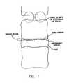
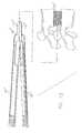
- FIG. 1is a front elevation view of two disc levels of the lumbar spine showing the prior art depth of resection resulting from drilling through the bony end plate region of adjacent vertebral bodies and showing the endplate region on a vertebral body;
- FIG. 2is a side view of one preferred embodiment of a guard of the present invention with the disc penetrating extensions closed into a first or insertion position;
- FIG. 3is a top and bottom view of the guard shown in FIG. 2;
- FIG. 4is a proximal or trailing end view of the guard shown in FIG. 2;
- FIG. 5is a side view of the guard of FIG. 2 with the disc penetrating extensions opened into a second or deployed position;
- FIG. 6is side view with a partial cross-section of a lock collar for use with the guard of FIG. 2;
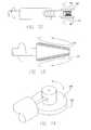
- FIG. 7is a perspective view of an impaction cap for use with the guard of FIG. 2;
- FIG. 8is a cross-sectional view of the impaction cap of FIG. 7 taken along line 8 - 8 of FIG. 7;
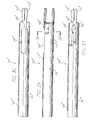
- FIG. 9is a top view of a cutting device configured to pass through the guard shown in FIG. 2;
- FIG. 10is a side view of the cutting device of FIG. 9;
- FIG. 11is a top view of the cutting device of FIG. 9 showing a spring-biased lever that may be used to adjust the position of a stop member;
- FIG. 12is a side view of a double-wheel cutting device having opposed abrading or cutting elements
- FIG. 13is a side view of a double-wheel cutting device having abrading or cutting surfaces inclined relative to one another to form a space between the adjacent vertebral bodies that approximate the lordotic curvature of a human spine at the location that will receive the implant;
- FIG. 14is a detailed view illustrating a single-wheel cutting device
- FIG. 15is a top plan view of a spinal interspace shaper bone removal device
- FIG. 16is a side elevation view of the bone removal device of FIG. 15;
- FIG. 17Ais a diagrammatic illustration of a hole pattern formed with a drill guide and large and small drills
- FIG. 17Bis a diagrammatic illustration of the hole pattern formed after the drill guide is flipped 180 degrees and additional holes are drilled with the large and small drill bits;
- FIG. 17Cis a diagrammatic illustration of the space created with the drill guide of FIG. 17B, but where the space to be prepared is wider than in FIG. 17B;
- FIG. 17Dis the configuration of the space created with the drill guide instrument and the holes drilled as shown in FIG. 17C;
- FIG. 17Eis a diagrammatic illustration of a hole drilled with a central bore drill guide into the space of FIG. 17D;
- FIG. 17Fis the configuration of the space created with the drill guide instrument and central bore drill guide instrument of FIG. 17E;
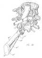
- FIG. 18is a rear perspective view of a lumbar segment of a spine with the dural sac retracted to the left showing a partial discectomy and the guard with disc penetrating extensions of FIG. 2 approaching the disc space between the adjacent vertebral bodies with the disc penetrating extensions in the first or insertion position;
- FIG. 19is a side view of the guard of FIG. 2 inserted fully within the spine with the disc penetrating extensions parallel to one another in the insertion position with the impaction cap of FIG. 7 and a portion of the trailing end of the guard in partial cross-section;
- FIG. 20is a side view of the guard of FIG. 2 in the deployed position with the disc penetrating extensions shown in the deployed position to induce lordosis to the vertebral bodies with the lock collar of FIG. 6 shown in partial cross-section coupled to the trailing end of the guard to maintain the guard in a closed position;
- FIG. 21shows a trailing end view of the guard of FIG. 2 in the deployed position between adjacent vertebral bodies with portions of the end plates of the adjacent vertebral bodies visible through the interior of the guard;
- FIG. 22shows a cross-sectional side view of the guard of FIG. 2 in the deployed position with the disc penetrating extensions in the deployed position to induce angulation to the adjacent vertebral bodies and a side view of the cutting device being inserted along tracks on the inside of the guard with the lock collar of FIG. 6 installed;
- FIG. 23Ais a cross-sectional view of the cutting device and guard along line 23 - 23 of FIG. 22 with the cutting device height approximating the height of the passage through the guard;
- FIG. 23Bis a cross-sectional view of an alternative embodiment of the cutting device and guard along line 23 - 23 of FIG. 22 with the cutting device height less than the height of the passage through the guard so as to permit passage through the guard of an implant having a height greater than the height of the insertion space formed through the guard;
- FIG. 24is a side view of the guard inserted into the adjacent vertebral bodies with the guard in the inserted position with the lock collar on the trailing end thereof and the disc penetrating extensions in the deployed position showing the portions of the vertebral end plates removed by the cutting device;
- FIG. 25is a partial cross-sectional side view of the guard of FIG. 2 showing a spinal fusion implant and inserter passing through the guard to insert an implant into the disc space between the adjacent vertebral bodies;
- FIG. 26shows a side view of the spinal segment with the implant of FIG. 25 inserted in the disc space and the guard with the disc penetrating extensions returned to the insertion position to facilitate the removal of the guard;
- FIG. 27is a top plan view of the lower vertebral body of the spinal segment of FIG. 26 with the spinal fusion implant inserted in the socket formed in the vertebral end plate region by the cutting device and a dashed line illustrating the location of a second socket to be formed in the vertebral body for placement of a second spinal fusion implant when the process is repeated;
- FIG. 28is a side view of another preferred embodiment of a guard of the present invention with the disc penetrating extensions closed into a first or insertion position;
- FIG. 29is a bottom view of the guard shown in FIG. 28;
- FIG. 30is a side view of the guard of FIG. 28 with the disc penetrating extensions opened into a second or deployed position;
- FIG. 31is an opposite side view of the guard of FIG. 28 with the disc penetrating extensions opened into a deployed position;
- FIG. 32is a cross-sectional view of the guard shown in FIG. 29 taken along line 32 - 32 of FIG. 29;
- FIG. 33is side cross-sectional view of a lock collar for use with the guard of FIGS. 30 and 31;
- FIG. 34is a side view of another preferred embodiment of a guard with the disc penetrating extensions opened into a deployed portion;
- FIG. 35is a side cross-sectional view of a lock collar for use with the guard of FIG. 34;
- FIG. 36is a perspective view of an impaction cap for use with the guard of FIG. 28 or FIG. 34;
- FIG. 37is a cross-sectional view of the impaction cap of FIG. 36 taken along line 37 - 37 of FIG. 36;
- FIG. 38is a rear perspective view of a lumbar segment of a spine with the dural sac retracted to the left showing a partial discectomy and the guard with disc penetrating extensions of FIG. 34 approaching the disc space between the adjacent vertebral bodies with the disc penetrating extensions in the insertion position;
- FIG. 39is a side view of the guard of FIG. 34 inserted fully within the spine with the disc penetrating extensions parallel to one another in the insertion position with the impaction cap of FIG. 36 and a portion of the trailing end of the guard in partial cross-section;
- FIG. 40is a side view of the guard of FIG. 34 in the deployed position with the disc penetrating extensions shown in the deployed position to induce lordosis to the vertebral bodies with the lock collar of FIG. 35 shown in partial cross-section coupled to the trailing end of the guard to maintain the guard in a closed position;
- FIG. 41shows a trailing end view of the guard of FIG. 34 in the deployed position between adjacent vertebral bodies with portions of the end plates of the adjacent vertebral bodies visible through the interior of the guard;
- FIG. 42shows a cross-sectional side view of the guard of FIG. 34 in the deployed position with the disc penetrating extensions in a deployed position to induce angulation to the adjacent vertebral bodies and a side view of a drill being inserted through the trailing end of the guard with the lock collar of FIG. 35 installed;
- FIG. 43is a partial cross-sectional side view of the guard of FIG. 34 inserted into the adjacent vertebral bodies with the locking cap of FIG. 35 on the trailing end thereof and the disc penetrating extensions in the deployed position showing the portions of the vertebral end plates removed by a bone removal device;
- FIG. 44is a partial cross-sectional side view of the guard of FIG. 34 and locking collar of FIG. 35 coupled thereto showing a spinal fusion implant and inserter passing through the guard to insert the implant into the disc space between the adjacent vertebral bodies;
- FIG. 45shows an exploded side view of the spinal segment with the implant of FIG. 44 inserted in the disc space and the guard with the disc penetrating extensions returned to the insertion position to facilitate the removal of the guard from between the adjacent vertebral bodies.
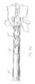
- FIGS. 2 - 5are generally directed to an embodiment of a guard having a rectangular cross-section for use in spinal surgery for forming an implantation space between adjacent vertebral bodies of the lumbar spine from a posterior approach.
- a guard 100has a body 102 with a first portion 104 and a second portion 106 .
- Guard 100also has disc penetrating extensions 110 , 112 .
- first disc penetrating extension 110extends from first portion 104 of body 102 and second disc penetrating extension 112 extends from second portion 106 of body 102 .
- various windows 108 in guard body 102allow the surgeon to remove portions of a facet, pedicle, or spinous process in the same procedure as the bone removal of the vertebral bodies for creating an insertion space therebetween. It is within the scope of the present invention to use a variety of window shapes in addition to the shape depicted to accommodate projecting bone structures. Window 108 also may be used in observing the procedure at various stages of the operation and if so desired for passing instruments therethrough. Rather than or in addition to a window 108 , the guard may have one or more indentations of the wall of the body 102 to make room for a facet, pedicle, or spinous process. As best seen in top view FIG. 3, disc-penetrating extensions 110 , 112 are preferably at least in part coextensive with the sides 114 of body 102 .
- FIG. 2shows guard 100 with body 102 with disc penetrating extensions 110 , 112 in a first or closed position, for insertion into the disc space between adjacent lumbar vertebral bodies to be operated upon.
- FIG. 5shows guard 100 with body 102 closed and disc penetrating extensions 110 , 112 in a second or expanded or deployed position.
- FIG. 4shows a proximal end view of guard 100 with exterior surface 116 , interior surface 118 , and hinges 120 .
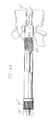
- FIG. 6is a side view with a partial cross-section of a lock collar 122 for use with guard 100 .
- Lock collar 122is used when body 102 of guard 100 is in the closed position to lock guard 100 into that position.
- FIG. 7A perspective view of an impaction cap 124 for use with guard 100 is shown in FIG. 7.
- FIG. 8is a cross-sectional view of impaction cap 124 .
- Impaction cap 124is fit over the proximal or trailing end of guard 100 with body 102 in the open position and disc penetrating extensions 110 , 112 in the closed, first, or insertion position. While it may be possible to insert the extensions of the guard into the disc space by holding the body of guard 100 , impaction cap 124 provides a contact surface 126 upon which force can be applied, such as with a mallet, to drive disc penetrating extensions 110 , 112 of guard 100 into the disc space between adjacent vertebral bodies.
- FIGS. 9 - 11show a cutting device 128 configured to pass through guard 100 for cutting the vertebral end plates of the adjacent vertebral bodies to form an implantation space for receipt of a spinal implant.
- Cutting device 128includes an upper cutter 130 and a lower cutter 132 , as disclosed in WO 99/63891.
- FIGS. 9 and 11are each a top view of cutting device 128 and FIG. 10 is a side view.
- upper and lower cutters 130 , 132are two disc-shaped members that mount on the distal end of the cutting device 128 by a recessed screw 134 and screw shaft (not shown).
- FIGS. 9 - 11show a cutting device 128 configured to pass through guard 100 for cutting the vertebral end plates of the adjacent vertebral bodies to form an implantation space for receipt of a spinal implant.
- Cutting device 128includes an upper cutter 130 and a lower cutter 132 , as disclosed in WO 99/63891.
- FIGS. 9 and 11are each a top view of cutting device 128
- FIG. 11is a top view of cutting device 128 showing a spring-biased lever 136 that may be used to adjust the position of a stop member 138 to limit the depth of insertion of cutting device 128 within guard 100 and thus into the spine.
- Cutting device 128may also be adapted to include cutters or abrading elements which have a pair of opposed, outwardly facing abrading surfaces or cutters 130 , 132 which lie in planes that may be parallel to each other, as shown in the embodiment of FIG. 12, or, alternatively, convergent to each other, as shown in FIG. 13.
- FIG. 14shows a single wheel embodiment of cutting device 128 .
- cutting device 128includes a single wheel 140 having a single abrading surface 142 that works on one vertebral surface at a time within the disc space.
- FIGS. 15 and 16show an improved spinal interspace shaper bone removal device 128 from the top plan view and side elevation view, respectively.
- Device 128includes drive members positioned adjacent cutting members, instead of between cutting members, to permit the overall height of device 128 to be less than was previously possible with cutting member having a drive member therebetween because cutting members can be placed closer together, as described in applicant's U.S. application Ser. No. 09/972,560, filed Oct. 6, 2001, incorporated herein by reference.
- FIGS. 17 A-Fshow another embodiment of a bone removal device useable with the guard of the present invention.
- a drill guide 144is used in combination with large drills and small drills as disclosed in U.S. Pat. No. 6,224,607, the disclosure of which is hereby incorporated by reference.
- the holes created with the large drills (L) and small drills (S)form a pattern as indicated in the dotted lines.
- guide 144is removed from within guard 100 , rotated 180 degrees and then reinserted into guard 100 .
- Guide 144is now oriented such that a large bore is positioned over the area in which the small holes were drilled and small bores are positioned over the area in which the large bore was drilled.
- the drilling procedure with large drills and small drillsis repeated to create a pattern of holes as indicated by the dotted lines in FIG. 17B.
- a substantial portion of boneis removed from the end plates of the adjacent vertebrae creating a space approximating the configuration of a rectangle.
- FIGS. 17E and 17Fshow the use of a large central bore (c) guide 146 .
- Guide 146has a large bore that is centrally placed, such that when a large drill is passed through central bore guide 146 , the portion of bone remaining in the central portion of the space being created can be removed.
- FIG. 17Cthe use of central bore guide 146 may be of particular value in removing remaining bone where guide 144 has a hole pattern that when reversed provides for a lesser amount of overlap of bores formed through the large bore.
- FIG. 17Dshows the space created with the drilling procedure through FIG. 17C.
- the hole created with central bore guide 146is shown in dotted line in FIG. 17E.
- FIG. 17Fthe space created with the drilling procedure disclosed above results in a substantial portion of bone being removed from the end plate of adjacent vertebrae creating a space that more closely approximates the configuration of a rectangle.
- FIGS. 18 - 27show the progression of various steps of a preferred method for using guard 100 and other associated equipment disclosed herein.
- FIG. 18is a perspective view of a segment of a spine viewed from a posterior aspect with the dural sac retracted to the left showing that a partial distectomy has already been performed.
- Guard 100 with disc penetrating extensions 110 , 112are shown approaching the disc space between the adjacent vertebral bodies with disc penetrating extensions 110 , 112 in the first or insertion position.
- Impaction cap 124is positioned on the proximal or trailing end of guard 100 to maintain it in the open position such that the disc penetrating extensions are closed into the insertion position. In this position, guard 100 is ready to be placed or driven into the disc space between the adjacent vertebral bodies.
- the extensions of guard 100are fully inserted into the spine with the disc penetrating extensions parallel to one another in the first or insertion position.
- Impaction cap 124is shown holding the guard in the open position and the disc penetrating extension in the first or insertion position. While the disc penetrating extensions of the first position are shown with a parallel orientation to one another, it is anticipated that the disc penetrating extensions may also be at an angle to one another in the first or closed position.
- body 102 of guard 100is shown in a closed position with the disc penetrating extensions shown in the second, open or inserted position to induce lordosis to the vertebral bodies.
- the proximal or trailing endhas lock collar 122 placed around it to maintain the body of guard 100 in the closed position.
- FIG. 21shows a proximal end view of guard 100 with the body in the closed and inserted position between adjacent vertebral bodies with portions of the end plates of the adjacent vertebral bodies visible through the interior of guard 100 .
- guard 100In FIG. 22 the body of guard 100 is in a closed position with disc penetrating extensions 110 , 112 in the second, expanded or inserted position to induce angulation to the adjacent vertebral bodies.
- a side view of cutting device 128At the distal end of guard 100 shown in cross-section is a side view of cutting device 128 being inserted along tracks 148 on interior surface 118 of guard 100 .
- Guard 100provides protected access to the disc space and the adjacent vertebral bodies for cutting device 128 via the elongated opening in guard 100 .
- an implant 150is preferably sized and shaped to match the space formed in the spine by cutting device 128 .
- the guard openingmay be taller than the height of cutting device 128 .
- Such a taller openingallows the implantation of an implant 150 taller than the height of cutting device 128 .
- Implant 150is then preferably sized and shaped without much regard to height so that a taller implant 150 may be selected for insertion to the space formed in the spine by cutting device 128 .
- Guard 100may also include one or more tracks 148 to direct cutting device 128 while accessing the disc space and adjacent vertebral bodies via the elongated opening in guard 100 .
- Such tracks 148may include any surface designed to direct cutting device 128 .
- Tracks 148also serve to keep cutter device 128 from easily rotating or moving side to side within the guard opening.
- FIGS. 23A and 23Bshow a cross-sectional view of cutter device 128 and guard 100 along line 23 — 23 of FIG. 22. In FIG. 24 after cutting device 128 is removed one can observe the portion of the vertebral end plates removed by cutting device 128 .
- an implant 150such as an impacted block, interbody fusion device, motion preserving device or other insert and an inserter 152 may be passed through guard 100 to insert implant 150 into the disc space between the adjacent vertebral bodies which guard may be left in place throughout the procedure.
- Implant 150may be made of artificial or naturally occurring materials suitable for implantation in the human spine. Implant 150 may also take a variety of shapes, for example, rectangular or square cross section. Implant 150 can comprise bone including, but not limited to, cortical bone. Implant 150 can also be formed of material other than bone, such as metal including, but not limited to, titanium and its alloys or ASTM material, surgical grade plastics, plastic composites, ceramics, or other materials suitable for use as an interbody implant. The plastics may be bioresorbable. Implant 150 can further be formed of bone growth promoting materials, including but not limited to, bone morphogenetic proteins, hydroxyapatite, and genes coding for the production of bone.
- bone growth promoting materialsincluding but not limited to, bone morphogenetic proteins, hydroxyapatite, and genes coding for the production of bone.
- Implant 150can be treated with a bone growth promoting substance, can be a source of osteogenesis, or can be at least in part bioabsorbable. Implant 150 also can be formed of a porous material. Further, implant 150 may be used in combination with chemical substances and/or compounds applied at the trailing end of the implant to inhibit scar formation, and a cap may be of benefit in shielding fusion-promoting substances contained in the implant from these scar formation inhibiting chemicals and compounds.
- body 102 of guard 100is opened and disc penetrating extensions 110 , 112 are thus placed in the first, closed position to facilitate the removal of guard 100 from the disc space. If not for the ability of the extensions to be retrieved from their lordotic inserted position, there would be no easy way to remove the guard.
- FIG. 27is a top plan view of the lower vertebral body of the spinal segment and spinal fusion implant 150 inserted in the implantation space or socket formed in the vertebral end plate by cutting device 128 .
- a dashed lineillustrates the location of a second implantation space or socket to be formed in the vertebral body for placement of a second spinal fusion implant when the process is repeated.
- a preferred method of the present inventionincludes: performing from a posterior approach in the lumber spine at least a partial laminectomy sufficient for access to the disc space; performing at least a partial discectomy, which more preferably provides sufficient space to receive the guard disc penetrating extensions to a depth which may be generally similar to the depth of implant 150 to be received; retracting and protecting the dural sac; inserting guard 100 with extensions 110 , 112 into the disc space; inducing lordosis to the adjacent vertebral bodies; securing body 102 of guard 100 in the closed position; and inserting cutting device 128 through guard 100 to a desired depth.
- the depth of insertionmay be monitored by x-ray.
- Implant 150may be inserted through guard 100 prior to its removal from the disc space, or may be inserted after guard 100 is removed while retractors are utilized as needed to protect the proximate neural structures.
- Guard 100preferably is used for posterior lumbar interbody implantation procedures.
- Guard 100includes a height, a width, and a distance between its front and rear portion.
- the height of body 102is preferably between 8-25 mm and the opening height is preferably 8-20 mm.
- the width of the opening of body 102is preferably 10-25 mm.
- Disc penetrating extensions 110 , 112may have any shape or configuration suitable for the intended purpose disclosed herein including extensions with parallel or angled upper and lower surfaces.
- disc penetrating extensions 110 , 112have a combined height when closed of 6-18 mm and a length of 12-32 mm.
- cutting device 128is preferably 8-20 mm in height and 10-25 mm in width. These dimensions could be greater or less and still be useful for their stated purpose while still being within the inventive scope of the present invention.
- FIGS. 28 - 31are directed to another embodiment of a guard in accordance with the present invention and generally referred to by the reference number 100 ′.
- Guard 100 ′has a circular cross-section or has at least opposed upper and lower arcuate portions.
- Guard 100 ′is adapted for use in spinal surgery for forming an implantation space between adjacent vertebral bodies of the lumbar spine from a posterior approach.
- the structure and use of guard 100 ′is similar to that described above in relation to guard 100 as illustrated in FIGS. 2 - 27 , hereby incorporated by reference, except as otherwise noted below.
- FIGS. 28 - 32show a guard 100 ′ similar to guard 100 except that it preferably has a circular cross-section or least opposed upper and lower arcuate portions.
- Guard 100 ′is preferably adapted to guide a bone removal device therethrough to form an implantation space having opposed arcuate surfaces into the endplates of the opposed arcuate surfaces.
- Such an implantation spaceis preferably adapted to receive an implant having at least one arcuate portion such as by way of example only implant 150 ′, illustrated in FIGS. 44 and 45 and described in more detail below.
- FIG. 28shows guard 100 ′ having a body 102 ′ with a first portion 104 ′ and a second portion 106 ′.
- Guard 100 ′also has disc penetrating extensions 110 ′, 112 ′.
- first disc penetrating extension 110 ′extends from first portion 104 ′ of body 102 ′
- second disc penetrating extension 112 ′extends from second portion 106 ′ of body 102 ′.
- FIGS. 28, 29, 31 , and 34show that guard 100 ′ may have one or more indentations 109 ′ of the wall of body 102 ′ to make room for a facet, pedicle, or spinous process of vertebrae adjacent to the disc space into which guard 100 ′ is to be inserted.
- Indentation 109 ′shown in FIG. 29, allows guard 100 ′ to clear the pedicle of the lower vertebra.
- Indentation 109 ′shown in FIG. 31, avoids interference with the bulge of the spinous process.
- indentation 109 ′ of FIG. 31could be a window to allow bone to protrude inside of guard 100 ′ to be cut off during the bone removal step of the surgical procedure.
- FIG. 34shows a side view of an alternative embodiment of guard 100 ′ including a threaded end 123 ′ cooperatively engaging lock collar 122 ′ of FIG. 35 having matching threads 125 ′. Threads 125 ′ of collar 122 ′ provide additional protection against accidental dislodgment of the locking collar from guard 100 ′ during a surgical procedure.
- guard 100 ′generally parallels the use of guard 100 shown in FIGS. 18 - 27 except that a bone removal device in the form of a drill 128 ′ is preferably used to prepare an implantation space sized and shaped to receive implant 150 ′.
- FIG. 38is a perspective view of a segment of a spine viewed from a posterior aspect with the dural sac retracted to the left showing that a partial discectomy has already been performed.
- Guard 100 ′ with disc penetrating extensions 110 ′, 112 ′are shown approaching the disc space between the adjacent vertebral bodies with disc penetrating extensions 110 ′, 112 ′ in the first or insertion position.
- Impaction cap 124 ′is positioned on the proximal or trailing end of guard 100 ′ to maintain it in the open position such that the disc penetrating extensions are closed into the insertion position. In this position, guard 100 ′ is ready to be placed or driven into the disc space between the adjacent vertebral bodies.
- FIGS. 39 and 40show guard 100 ′ rotationally articulating to permit movement of disc penetrating extensions 110 ′, 112 ′ in response to movement of first portion 104 ′ and second portion 106 ′ of body 102 ′ relative to one another.
- the rotational articulationpreferably occurs about hinge 120 ′, which is preferably formed in first and second portions 104 ′, 106 ′ of body 102 ′.
- guard 100 ′In FIG. 42 the body of guard 100 ′ is in a closed position with disc penetrating extensions 110 ′, 112 ′ in the second, expanded or inserted position to induce angulation to the adjacent vertebral bodies.
- a side view of drill 128 ′At the distal end of guard 100 ′ shown in cross-section is a side view of drill 128 ′ being inserted through guard 100 ′.
- Guard 100 ′provides protected access to the disc space and the adjacent vertebral bodies for drill 128 ′ via the elongated opening in guard 100 ′.
- a preferred embodiment of threaded implant 150 ′has a body sized to match the implantation space formed in the spine by drill 128 ′ and is screwed into the adjacent vertebral bodies.
- Drill 128 ′may have a reduced diameter cutting portion relative to the shaft diameter or may be inserted through an inner sleeve that passes into guard 100 ′ to guide drill 128 ′ to form an implantation space smaller than the passage through guard 100 ′.
- the interior opening of guard 100 ′may be taller than the height of the cutting portion of drill 128 ′. Such a taller opening allows the implantation of an implant 150 ′ taller than the height of the cutting portion of drill 128 ′.
- Implant 150 ′may be threaded, ratcheted, knurled, or have any other surface projections to facilitate engaging the adjacent vertebral bodies. Implant 150 ′ may also have a variety of shapes, for example, circular or oval in cross section. Implant 150 ′ can comprise, be formed of, and/or be treated with materials and/or substances such as those described above relative to implant 150 .
- Guard 100 ′preferably is used for posterior lumbar interbody implantation procedures.
- Guard 100 ′includes a height, a width, and a distance between its front and rear portion.
- the height of body 102 ′is preferably between 8-25 mm and the opening height is preferably 8-20 mm.
- Disc penetrating extensions 110 ′, 112 ′may have any shape or configuration suitable for the intended purpose disclosed herein including extensions with parallel or angled upper and lower surfaces in the closed or open position.
- disc penetrating extensions 110 ′, 112 ′have a combined height when closed of 6-18 mm and a length of 12-32 mm.
- drill 128 ′is preferably 8-20 mm in height. These dimensions could be greater or less and still be useful for their intended purpose while still being within the inventive scope of the present invention.
Landscapes
- Health & Medical Sciences (AREA)
- Life Sciences & Earth Sciences (AREA)
- Surgery (AREA)
- Biomedical Technology (AREA)
- Engineering & Computer Science (AREA)
- Orthopedic Medicine & Surgery (AREA)
- Public Health (AREA)
- Animal Behavior & Ethology (AREA)
- General Health & Medical Sciences (AREA)
- Veterinary Medicine (AREA)
- Heart & Thoracic Surgery (AREA)
- Nuclear Medicine, Radiotherapy & Molecular Imaging (AREA)
- Medical Informatics (AREA)
- Molecular Biology (AREA)
- Oral & Maxillofacial Surgery (AREA)
- Dentistry (AREA)
- Transplantation (AREA)
- Neurology (AREA)
- Cardiology (AREA)
- Vascular Medicine (AREA)
- Physical Education & Sports Medicine (AREA)
- Pathology (AREA)
- Radiology & Medical Imaging (AREA)
- Prostheses (AREA)
- Surgical Instruments (AREA)
- Materials For Medical Uses (AREA)
- Orthopedics, Nursing, And Contraception (AREA)
Abstract
Description
- This application claims the benefit of U.S. utility application Ser. No. 10/061,236, filed Feb. 4, 2002, U.S. provisional application No. 60/272,381, filed Mar. 1, 2001, U.S. provisional application No. 60/272,382, filed Mar. 1, 2001, and U.S. utility application Nos. ______ (unassigned), both entitled “Dynamic Lordotic Guard with movable Extensions for Creating an Implantation Space Posteriorly in the Lumbar Spine and Method for Use Thereof,” both filed Mar. 1, 2002, the disclosures of which are all incorporated herein by reference.[0001]
- The present invention relates to a device for implantation into a disc space between adjacent vertebral bodies in the human spine, and a device and method for working on those portions of the vertebral bodies adjacent that disc space to remove bone material and thereby access vascular bone, and preferably a device and method for protecting the neurological structures such as nerve roots and dural sac proximate the implantation site while providing protected access to form an implantation space and then access the implantation space formed between the adjacent vertebral bodies for insertion of an implant therein. The device and associated method are used to position (space apart and align) the vertebral bodies, guide the formation of a surface into or through each of the vertebral body surfaces that are adjacent the intervertebral disc space, and may further be utilized to guide an interbody spinal implant into the implantation space.[0002]
- In one embodiment, the device and associated method are used to make an implantation space to insert an implant of a height having a known correspondence to the height of the space created. In another embodiment, the device and associated method are used to make an implantation space of known and specific dimensions (e.g., width; depth; and height) and with certain preferred embodiments, permit passage through the device of an implant having a height greater than the height of the implantation space formed through the device.[0003]
- Human vertebral bodies are comprised of a dense, hard outer shell and a relatively less dense inner mass. The hard outer shell is very densely compacted cancellous bone, resembling cortical bone at all but high magnification, and is generally referred to as the cortex. The inner mass is a softer cancellous bone. As shown in FIG. 1, the outer shell of cortex bone (the bony endplate) that is adjacent the disc and the bone immediately beneath that bone (both are subchondral, that is, beneath the cartilage layer or cartilaginous endplate that separates the bone from the disc), are defined for the specific purposes of this specification to comprise the “end plate region” to avoid any confusion that might otherwise arise from any inconsistency in the use of any of these terms. While it is understood that these terms may have other meanings more ordinary or special, and that those of ordinary skill in the art might otherwise differ as to the correct meanings of these terms, it is exactly for the purpose of removing any ambiguity that these terms are being so precisely defined specifically for this specification.[0004]
- The spinal disc that resides between adjacent vertebral bodies maintains the spacing between those vertebral bodies and, in a healthy spine, allows for relative motion between the vertebrae. At the time of surgery, for example in the instance of interbody fusion, that is, where fusion is intended to occur between adjacent vertebral bodies of a patient's spine, the surgeon typically prepares an opening at the site of the intended fusion by removing a substantial amount of the nucleus disc material that exists between the adjacent vertebral bodies to be fused. Because the outermost layers of bone of the vertebral end plate are relatively inert to new bone growth, the surgeon will typically work on the end plate to remove at least the outermost cell layers of bone to gain access to the blood-rich, vascular bone tissue within the vertebral body. In this manner, the vertebrae are prepared in a way that encourages new bone growth consistent with fusion.[0005]
- Devices for assisting a surgeon in accessing the disc space and adjacent vertebral bodies are known. Drill guides and boxed chisels have been used to form an implantation space between the adjacent vertebral bodies for insertion of a spinal implant therein. Applicant invented a guard and instrument system particularly well suited for use in the lumbar spine and of unequalled advantage for use posteriorly therein through which both the implantation space can be formed and a spinal implant can be inserted into the implantation space, as disclosed in U.S. Pat. No. 5,015,247, filed Jun. 13, 1988, which is hereby incorporated by reference.[0006]
- Applicant also invented a guard having disc penetrating extension(s), which extensions have utility for stabilizing the guard, stabilizing the adjacent vertebrae relative to each other, urging the vertebrae apart if desired, and aligning the vertebrae to each other if desired to form the implantation space through the guard and insert the spinal implant through the guard into the implantation space, as disclosed in U.S. Pat. No. 6,080,155 filed Feb. 27, 1995, incorporated herein by reference. The disc penetrating extensions can have either parallel or angled upper and lower surfaces in contact with the adjacent vertebral bodies to place the adjacent vertebral bodies parallel to one another or at an angle to one another. The disclosed disc penetrating extensions are rigid.[0007]
- To obtain a particular orientation between the adjacent vertebral bodies a surgeon selects a guard having a predetermined orientation between the upper and lower surfaces of the disc penetrating extensions. In the case of disc penetrating extensions that have upper and lower surfaces diverging from one another as would be useful for posterior lumbar interbody fusion (PLIF), so as to be higher at the insertion or distal end than at the trailing or proximal end of the extensions, a tapered leading end is used to facilitate insertion of the disc penetrating extensions into the disc space. Such a configuration allows for lordosis of the lumbar segment of a spine to be operated upon from a posterior approach. For extensions that have diverging upper and lower surfaces, additional force is required to drive the guard and extensions into place. Then, after an implant is inserted, it may be difficult to remove a distractor element such as a guard having disc penetrating extensions having a maximum height greater then the height of the disc space posterior height.[0008]
- Present methods of forming the implantation space between adjacent vertebral bodies generally include the use of one or more of the following: hand held biting and grasping instruments known as rongeurs; drills and drill guides; rotating burrs driven by a motor; and osteotomes and chisels. Applicant has taught various novel instruments to mill out the recipient fusion site across the height of the disc space including various cutting/milling frames and various novel cutters as disclosed in applicant's U.S. Pat. No. 6,159,214, incorporated herein by reference. The surgeon must work upon the adjacent end plates of the adjacent vertebrae to access the vascular, cancellous bone that is best suited for participating in the fusion and causing active bone growth, and also to attempt to obtain an appropriately shaped surface in the vertebral bodies to receive the implant. Because the end plates of the adjacent vertebrae are not flat, but rather have a complex biological as opposed to geometrical curved shape, it is necessary to conform the vertebrae to the shape of the implant to be received therebetween.[0009]
- Suitable devices for forming a disc space disclosed by applicant in U.S. Pat. No. 6,083,228, and U.S. patent application Ser. No. 09/663,311, filed Sep. 15, 2000, both of which are hereby incorporated by reference. Both of these disclosures describe various abrading elements and cutting wheels used to form the implantation space. U.S. patent application Ser. No. 09/663,311 discloses the use of a guard or frame having disc penetrating extensions that could be either parallel or angled to properly orient the vertebral bodies relative to one another prior to forming the implantation space.[0010]
- There is a need for a guard for use in posterior lumbar surgery to create an interbody implantation space while providing for spinal lordosis and while being easily and safely inserted and as easily and safely removed.[0011]
- In accordance with the purposes of the present invention, as embodied and broadly described herein, a guard of this invention is provided for use in spinal surgery across a disc space between two adjacent vertebral bodies of a human spine. The guard includes a body having a leading end and an opposite trailing end. The body has a first portion and a second portion proximate the leading end that are in pivotal relationship to one another between an open position and a closed position. The first and second portions each have opposed interior portions that define an opening for providing protected access to the disc space and the adjacent vertebral bodies. The opposed interior portions are adapted to guide a bone removal device therethrough that is sized to form an implantation space across the disc space and at least in part into the adjacent vertebral bodies. The guard also includes at least one disc space penetrating extension extending from the leading end of the body that is adapted for insertion at least in part into the disc space. The extension has a first portion extending from the first portion of the body that has a contact surface adapted to bear against one of the adjacent endplates of the adjacent vertebral bodies. The extension also has a second portion extending from the second portion of the body that has a contact surface adapted to bear against the other of the adjacent endplates of the adjacent vertebral bodies. The contact surfaces of the first and second portions of the extension are in pivotal relationship to one another from an insertion position to a deployed position to move the adjacent vertebral bodies apart upon movement of the first and second portions of the body from the open position to the closed position.[0012]
- The body of the guard may have a generally rectangular, square, circular, oval, or elliptical cross section along at least a portion of the length of the body. The leading end of the body may be adapted to conform at least in part to the exterior surfaces of the adjacent vertebral bodies by having the leading end cut back to permit the contact surfaces to have an intimate fit with the vertebral bodies when the guard is in the deployed position. The body may include at least one window adapted to permit the surgeon to observe the surgery though the window and/or permit portions of bone extending though the window to be removed by the bone removal device passing through the body of the guard.[0013]
- The guard may include a second disc penetrating extension diametrically opposite to a first disc penetrating extension. Each disc penetrating extension may have a tapered leading end and have contact surfaces that are parallel to each other over a substantial portion of the length of each extension when in the insertion position. The first and second portions of each disc penetrating extension may be adapted to touch one another when in the insertion position.[0014]
- The first and second portions of the body may be hinged to one another to rotatably articulate relative to one another about an axis of rotation that is fixed relative to the mid-longitudinal axis of the guard when moved from the open position to the closed position. The body may have an interior surface having a cooperating surface for guiding a corresponding cooperating surface on the bone removal device.[0015]
- The guard may include an impaction cap adapted to cooperatively engage the trailing end of the body when the body is in the open position. The guard may include a lock in the form of a collar adapted to cooperatively engage the body of the guard when the body is in the closed position to hold the body in the closed position.[0016]
- The guard may form part of a combined spinal surgery set that includes a bone removal device, an implant driver, and a spinal implant, or any combination thereof. The bone removal device may have a working end having at least two cutters selected to create a predetermined surface contour into each of the adjacent vertebral bodies as the working end is moved. The implant may be sized and shaped to at least in part match the space formed in the spine by the bone removal device and may be adapted to be combined or treated with a natural or artificial bone growth promoting material or substance.[0017]
- In accordance with the purposes of another embodiment of the present invention, as embodied and broadly described herein, a guard of this invention is provided for use in spinal surgery across a disc space between two adjacent vertebral bodies of the human spine. The guard includes a body having an opening for providing protected access to the disc space and the adjacent vertebral bodies. The opening has opposed interior portions that are adapted to guide therethrough a bone removal device sized to form an implantation space across the disc space and at least in part into the adjacent vertebral bodies. The guard also includes at least one disc space penetrating extension extending from the body that is adapted for insertion at least in part into the disc space. The disc penetrating extension has a first portion having a contact surface adapted to bear against one of the adjacent endplates of the adjacent vertebral bodies and a second portion having a contact surface adapted to bear against the other of the adjacent endplates of the adjacent vertebral bodies. The contact surfaces of the first and second portions are adapted to rotatably articulate relative to one another between an insertion position and a deployed position to move the adjacent vertebral bodies apart.[0018]
- In accordance with the purposes of a further embodiment of the present invention, as embodied and broadly described herein, a method of this invention is provided for inserting a spinal implant at least in part within and across the generally restored height of a disc space between two adjacent vertebral bodies of a human spine. The method includes the steps of positioning into the disc space between the adjacent vertebral bodies a guard having a body and an extension for insertion at least in part into the disc space and for bearing against end plates of the adjacent vertebral bodies to restore the spacing of the disc space between the adjacent vertebrae, the guard having a first portion oriented toward one of the adjacent vertebral bodies and a second portion oriented toward another of the adjacent vertebral bodies, the first and second portions being rotatably articulating relative to one another such that when the body moves from an open position to a closed position the extension moves from an insertion position to a deployed position to move the adjacent vertebral bodies apart; rotatably articulating the guard to move the body from the open position to the closed position and the extension from the insertion position to the deployed position to move the adjacent vertebral bodies apart; and forming, through the guard, an opening across height of the disc space and into at least a portion of the endplates of the adjacent vertebral bodies.[0019]
- The method may include the further steps of performing the spinal implant surgery from a position posterior to the transverse processes of the vertebrae adjacent the disc space; performing the procedure on both sides of the spinal midline of the spine; securing the body of the guard in the closed position; and inserting two implants into the spine.[0020]
- The positioning step may include the further steps of positioning a guard having multiple extensions for insertion into the disc space; placing the body of the guard in the open position; driving the extension into the disc space; and inducing angulation to the adjacent vertebral bodies relative to one another.[0021]
- The rotatably articulating step may include the further steps of orienting the adjacent vertebral bodies in a predetermined relationship relative to each other; and inducing lordosis to the adjacent vertebral bodies.[0022]
- The forming step may include the further steps of inserting the bone removal device through the guard to a desired depth; forming the implantation space with the bone removal device; and forming opposed receiving surfaces in the end plates of the vertebral bodies corresponding at least in part in size, shape, and contour to an implant to be implanted. The forming step may include any one of milling, drilling, reaming, abrading, chiseling, and trephining the implantation space.[0023]
- The method may include the further steps of inserting the implant into the implantation space through the guard, or inserting the implant into the implantation space after removing the guard from the disc space. The inserting step may include the further steps of inserting the implant using an implant inserter; and removing the implant inserter after using the implant inserter to insert the implant into the implantation space. The inserting step may also include inserting a spinal implant that is a spinal fusion implant that has upper and lower surfaces for placement between and in contact with the adjacent vertebral bodies, each of the upper and lower surfaces having at least one opening adapted to permit for the growth of bone from adjacent vertebral body to adjacent vertebral body through the implant. The inserting step may include inserting a spinal implant having a hollow between the upper and lower surfaces; inserting a spinal implant that is expandable; and inserting a spinal implant having surface projections configured to resist expulsion of the implant from the implantation space. The inserting step may include inserting any one of an inert spacer, an artificial disc, or a bone graft.[0024]
- The inserting step may further include the steps of compressively loading the implant with fusion promoting substances selected from one of bone, bone derived products, demineralized bone matrix, ossifying proteins, bone morphogenetic protein, hydroxyapatite, and genes coding for the production of bone; and retaining the fusion promoting substance within the implant after the loading step. The step of retaining the fusion promoting substance may include attaching a cap to the implant.[0025]
- The inserting step may also include the steps of treating the implant with a fusion promoting substance; inserting an implant in combination with a chemical substance adapted to inhibit scar formation; inserting an implant in combination with an antimicrobial material; inserting an implant including a fusion promoting substance or having a bone ingrowth surface; inserting an implant being at least in part of one of bone and bone growth promoting material; and inserting an implant in combination with at least one of a fusion promoting substance, bone, bone growth promoting material, bone derived products, demineralized bone matrix, ossifying proteins, bone morphogenetic protein, hydroxyapatite, and genes coding for the production of bone.[0026]
- The method may further include the steps of collapsing the extensions and removing the guard form the disc space.[0027]
- The accompanying drawings, which are incorporated in and constitute a part of this specification, are by way of example only and not limitation, and illustrate several embodiments of the invention, which together with the description, serve to explain the principles of the invention. The scope of the invention is limited only by the scope of the claims as from the present teachings other embodiments of the present invention shall be apparent to those skilled in the art.[0028]
- The present invention has a number of embodiments, at least some of which have as an object of at least one embodiment of the present invention to provide a device and method for quickly, safely, effectively, and accurately spacing apart and positioning a pair of adjacent vertebral bodies to receive an implant, which is anything designed to be left in the body for an extended length of time, working upon the properly positioned vertebral body end plate regions adjacent a disc space so as to remove bone to produce a receiving surface corresponding to an implant having upper and lower surfaces to be implanted between the adjacent vertebrae.[0029]
- It is a further object of at least one embodiment of the present invention to provide a device and method that permits the insertion of disc penetrating extensions of a guard into the disc space posteriorly in a first position that facilitates insertion and removal of the disc penetrating extensions into and from the disc space and then permits the disc penetrating extensions to be moved into a second position that orients the adjacent vertebral bodies in a preferred lordotic relationship relative to the device and each other.[0030]
- It is a further object of the present invention, in at least certain embodiments, to provide a device capable of working upon both of the vertebral body end plate regions adjacent a disc space to produce opposed receiving surfaces in the adjacent end plates corresponding at least in part in size, shape, and contour to an implant to be implanted with the exception of the height of the implant, which may be greater than the distance between the opposed receiving surfaces that may be distracted or otherwise moved apart by insertion of the implant, and in so doing to define the shape to the implantation space.[0031]
- It is a further object of the present invention to provide a device that works with linear insertion, i.e., insertion along a single axis, and without removing the device during the process of disc space preparation and, if so desired with certain embodiments of the present invention, implant placement.[0032]
- These and other objectives of the present invention will occur to those of ordinary skill in the art based on the description of the preferred embodiments of the present invention described below. However, not all embodiments of the inventive features of the present invention need achieve all the objectives identified above, and the invention in its broadest aspects is not limited to the preferred embodiments described herein.[0033]
- The accompanying drawings together with the description, serve to explain the objects, advantages, and principles of the invention. In the drawings:[0034]
- FIG. 1 is a front elevation view of two disc levels of the lumbar spine showing the prior art depth of resection resulting from drilling through the bony end plate region of adjacent vertebral bodies and showing the endplate region on a vertebral body;[0035]
- FIG. 2 is a side view of one preferred embodiment of a guard of the present invention with the disc penetrating extensions closed into a first or insertion position;[0036]
- FIG. 3 is a top and bottom view of the guard shown in FIG. 2;[0037]
- FIG. 4 is a proximal or trailing end view of the guard shown in FIG. 2;[0038]
- FIG. 5 is a side view of the guard of FIG. 2 with the disc penetrating extensions opened into a second or deployed position;[0039]
- FIG. 6 is side view with a partial cross-section of a lock collar for use with the guard of FIG. 2;[0040]
- FIG. 7 is a perspective view of an impaction cap for use with the guard of FIG. 2;[0041]
- FIG. 8 is a cross-sectional view of the impaction cap of FIG. 7 taken along line[0042]8-8 of FIG. 7;
- FIG. 9 is a top view of a cutting device configured to pass through the guard shown in FIG. 2;[0043]
- FIG. 10 is a side view of the cutting device of FIG. 9;[0044]
- FIG. 11 is a top view of the cutting device of FIG. 9 showing a spring-biased lever that may be used to adjust the position of a stop member;[0045]
- FIG. 12 is a side view of a double-wheel cutting device having opposed abrading or cutting elements;[0046]
- FIG. 13 is a side view of a double-wheel cutting device having abrading or cutting surfaces inclined relative to one another to form a space between the adjacent vertebral bodies that approximate the lordotic curvature of a human spine at the location that will receive the implant;[0047]
- FIG. 14 is a detailed view illustrating a single-wheel cutting device;[0048]
- FIG. 15 is a top plan view of a spinal interspace shaper bone removal device;[0049]
- FIG. 16 is a side elevation view of the bone removal device of FIG. 15;[0050]
- FIG. 17A is a diagrammatic illustration of a hole pattern formed with a drill guide and large and small drills;[0051]
- FIG. 17B is a diagrammatic illustration of the hole pattern formed after the drill guide is flipped 180 degrees and additional holes are drilled with the large and small drill bits;[0052]
- FIG. 17C is a diagrammatic illustration of the space created with the drill guide of FIG. 17B, but where the space to be prepared is wider than in FIG. 17B;[0053]
- FIG. 17D is the configuration of the space created with the drill guide instrument and the holes drilled as shown in FIG. 17C;[0054]
- FIG. 17E is a diagrammatic illustration of a hole drilled with a central bore drill guide into the space of FIG. 17D;[0055]
- FIG. 17F is the configuration of the space created with the drill guide instrument and central bore drill guide instrument of FIG. 17E;[0056]
- FIG. 18 is a rear perspective view of a lumbar segment of a spine with the dural sac retracted to the left showing a partial discectomy and the guard with disc penetrating extensions of FIG. 2 approaching the disc space between the adjacent vertebral bodies with the disc penetrating extensions in the first or insertion position;[0057]
- FIG. 19 is a side view of the guard of FIG. 2 inserted fully within the spine with the disc penetrating extensions parallel to one another in the insertion position with the impaction cap of FIG. 7 and a portion of the trailing end of the guard in partial cross-section;[0058]
- FIG. 20 is a side view of the guard of FIG. 2 in the deployed position with the disc penetrating extensions shown in the deployed position to induce lordosis to the vertebral bodies with the lock collar of FIG. 6 shown in partial cross-section coupled to the trailing end of the guard to maintain the guard in a closed position;[0059]
- FIG. 21 shows a trailing end view of the guard of FIG. 2 in the deployed position between adjacent vertebral bodies with portions of the end plates of the adjacent vertebral bodies visible through the interior of the guard;[0060]
- FIG. 22 shows a cross-sectional side view of the guard of FIG. 2 in the deployed position with the disc penetrating extensions in the deployed position to induce angulation to the adjacent vertebral bodies and a side view of the cutting device being inserted along tracks on the inside of the guard with the lock collar of FIG. 6 installed;[0061]
- FIG. 23A is a cross-sectional view of the cutting device and guard along line[0062]23-23 of FIG. 22 with the cutting device height approximating the height of the passage through the guard;
- FIG. 23B is a cross-sectional view of an alternative embodiment of the cutting device and guard along line[0063]23-23 of FIG. 22 with the cutting device height less than the height of the passage through the guard so as to permit passage through the guard of an implant having a height greater than the height of the insertion space formed through the guard;
- FIG. 24 is a side view of the guard inserted into the adjacent vertebral bodies with the guard in the inserted position with the lock collar on the trailing end thereof and the disc penetrating extensions in the deployed position showing the portions of the vertebral end plates removed by the cutting device;[0064]
- FIG. 25 is a partial cross-sectional side view of the guard of FIG. 2 showing a spinal fusion implant and inserter passing through the guard to insert an implant into the disc space between the adjacent vertebral bodies;[0065]
- FIG. 26 shows a side view of the spinal segment with the implant of FIG. 25 inserted in the disc space and the guard with the disc penetrating extensions returned to the insertion position to facilitate the removal of the guard;[0066]
- FIG. 27 is a top plan view of the lower vertebral body of the spinal segment of FIG. 26 with the spinal fusion implant inserted in the socket formed in the vertebral end plate region by the cutting device and a dashed line illustrating the location of a second socket to be formed in the vertebral body for placement of a second spinal fusion implant when the process is repeated;[0067]
- FIG. 28 is a side view of another preferred embodiment of a guard of the present invention with the disc penetrating extensions closed into a first or insertion position;[0068]
- FIG. 29 is a bottom view of the guard shown in FIG. 28;[0069]
- FIG. 30 is a side view of the guard of FIG. 28 with the disc penetrating extensions opened into a second or deployed position;[0070]
- FIG. 31 is an opposite side view of the guard of FIG. 28 with the disc penetrating extensions opened into a deployed position;[0071]
- FIG. 32 is a cross-sectional view of the guard shown in FIG. 29 taken along line[0072]32-32 of FIG. 29;
- FIG. 33 is side cross-sectional view of a lock collar for use with the guard of FIGS. 30 and 31;[0073]
- FIG. 34 is a side view of another preferred embodiment of a guard with the disc penetrating extensions opened into a deployed portion;[0074]
- FIG. 35 is a side cross-sectional view of a lock collar for use with the guard of FIG. 34;[0075]
- FIG. 36 is a perspective view of an impaction cap for use with the guard of FIG. 28 or FIG. 34;[0076]
- FIG. 37 is a cross-sectional view of the impaction cap of FIG. 36 taken along line[0077]37-37 of FIG. 36;
- FIG. 38 is a rear perspective view of a lumbar segment of a spine with the dural sac retracted to the left showing a partial discectomy and the guard with disc penetrating extensions of FIG. 34 approaching the disc space between the adjacent vertebral bodies with the disc penetrating extensions in the insertion position;[0078]
- FIG. 39 is a side view of the guard of FIG. 34 inserted fully within the spine with the disc penetrating extensions parallel to one another in the insertion position with the impaction cap of FIG. 36 and a portion of the trailing end of the guard in partial cross-section;[0079]
- FIG. 40 is a side view of the guard of FIG. 34 in the deployed position with the disc penetrating extensions shown in the deployed position to induce lordosis to the vertebral bodies with the lock collar of FIG. 35 shown in partial cross-section coupled to the trailing end of the guard to maintain the guard in a closed position;[0080]
- FIG. 41 shows a trailing end view of the guard of FIG. 34 in the deployed position between adjacent vertebral bodies with portions of the end plates of the adjacent vertebral bodies visible through the interior of the guard;[0081]
- FIG. 42 shows a cross-sectional side view of the guard of FIG. 34 in the deployed position with the disc penetrating extensions in a deployed position to induce angulation to the adjacent vertebral bodies and a side view of a drill being inserted through the trailing end of the guard with the lock collar of FIG. 35 installed;[0082]
- FIG. 43 is a partial cross-sectional side view of the guard of FIG. 34 inserted into the adjacent vertebral bodies with the locking cap of FIG. 35 on the trailing end thereof and the disc penetrating extensions in the deployed position showing the portions of the vertebral end plates removed by a bone removal device;[0083]
- FIG. 44 is a partial cross-sectional side view of the guard of FIG. 34 and locking collar of FIG. 35 coupled thereto showing a spinal fusion implant and inserter passing through the guard to insert the implant into the disc space between the adjacent vertebral bodies; and[0084]
- FIG. 45 shows an exploded side view of the spinal segment with the implant of FIG. 44 inserted in the disc space and the guard with the disc penetrating extensions returned to the insertion position to facilitate the removal of the guard from between the adjacent vertebral bodies.[0085]
- Reference is now made in detail to the present preferred embodiments of the invention, as illustrated in the accompanying drawings. Wherever possible, the same reference numbers are used throughout the drawings to refer to the same or like parts. For example, reference numbers without a prime are used in relation to a guard having a rectangular cross-section such as described with reference to FIGS.[0086]2-27. Reference numbers with a prime are used in relation to a guard having a circular cross-section or opposed upper and lower arcuate portions such as described with reference to FIGS.28-45.
- FIGS.[0087]2-5 are generally directed to an embodiment of a guard having a rectangular cross-section for use in spinal surgery for forming an implantation space between adjacent vertebral bodies of the lumbar spine from a posterior approach. As shown in FIG. 2, a
guard 100 has abody 102 with afirst portion 104 and asecond portion 106.Guard 100 also hasdisc penetrating extensions disc penetrating extension 110 extends fromfirst portion 104 ofbody 102 and seconddisc penetrating extension 112 extends fromsecond portion 106 ofbody 102. - In preferred embodiments, but not requisite,[0088]
various windows 108 inguard body 102 allow the surgeon to remove portions of a facet, pedicle, or spinous process in the same procedure as the bone removal of the vertebral bodies for creating an insertion space therebetween. It is within the scope of the present invention to use a variety of window shapes in addition to the shape depicted to accommodate projecting bone structures.Window 108 also may be used in observing the procedure at various stages of the operation and if so desired for passing instruments therethrough. Rather than or in addition to awindow 108, the guard may have one or more indentations of the wall of thebody 102 to make room for a facet, pedicle, or spinous process. As best seen in top view FIG. 3, disc-penetratingextensions sides 114 ofbody 102. - FIG. 2 shows[0089]
guard 100 withbody 102 withdisc penetrating extensions guard 100 withbody 102 closed anddisc penetrating extensions guard 100 withexterior surface 116,interior surface 118, and hinges120. - FIG. 6 is a side view with a partial cross-section of a[0090]
lock collar 122 for use withguard 100.Lock collar 122 is used whenbody 102 ofguard 100 is in the closed position to lockguard 100 into that position. - A perspective view of an[0091]
impaction cap 124 for use withguard 100 is shown in FIG. 7. FIG. 8 is a cross-sectional view ofimpaction cap 124.Impaction cap 124 is fit over the proximal or trailing end ofguard 100 withbody 102 in the open position anddisc penetrating extensions guard 100,impaction cap 124 provides acontact surface 126 upon which force can be applied, such as with a mallet, to drivedisc penetrating extensions guard 100 into the disc space between adjacent vertebral bodies. - A variety of bone removal devices are useable with the guard of the present invention. For example, FIGS.[0092]9-11 show a
cutting device 128 configured to pass throughguard 100 for cutting the vertebral end plates of the adjacent vertebral bodies to form an implantation space for receipt of a spinal implant. Cuttingdevice 128 includes anupper cutter 130 and alower cutter 132, as disclosed in WO 99/63891. FIGS. 9 and 11 are each a top view of cuttingdevice 128 and FIG. 10 is a side view. In this embodiment, upper andlower cutters cutting device 128 by a recessedscrew 134 and screw shaft (not shown). In the embodiment of the present invention shown in FIGS.9-11, the upper andlower cutters device 128 as the cutters remove the requisite material through the vertebral end plate regions. Counter-rotating motion ofcutters Cutters device 128. FIG. 11 is a top view of cuttingdevice 128 showing a spring-biasedlever 136 that may be used to adjust the position of astop member 138 to limit the depth of insertion of cuttingdevice 128 withinguard 100 and thus into the spine. Cuttingdevice 128 may also be adapted to include cutters or abrading elements which have a pair of opposed, outwardly facing abrading surfaces orcutters - FIG. 14 shows a single wheel embodiment of cutting[0093]
device 128. In FIG. 14, cuttingdevice 128 includes asingle wheel 140 having asingle abrading surface 142 that works on one vertebral surface at a time within the disc space. - FIGS. 15 and 16 show an improved spinal interspace shaper[0094]
bone removal device 128 from the top plan view and side elevation view, respectively.Device 128 includes drive members positioned adjacent cutting members, instead of between cutting members, to permit the overall height ofdevice 128 to be less than was previously possible with cutting member having a drive member therebetween because cutting members can be placed closer together, as described in applicant's U.S. application Ser. No. 09/972,560, filed Oct. 6, 2001, incorporated herein by reference. - FIGS.[0095]17A-F show another embodiment of a bone removal device useable with the guard of the present invention. In this embodiment, a
drill guide 144 is used in combination with large drills and small drills as disclosed in U.S. Pat. No. 6,224,607, the disclosure of which is hereby incorporated by reference. As shown in FIG. 17A, the holes created with the large drills (L) and small drills (S) form a pattern as indicated in the dotted lines. After the first three holes have been drilled, guide144 is removed from withinguard 100, rotated 180 degrees and then reinserted intoguard 100.Guide 144 is now oriented such that a large bore is positioned over the area in which the small holes were drilled and small bores are positioned over the area in which the large bore was drilled. The drilling procedure with large drills and small drills is repeated to create a pattern of holes as indicated by the dotted lines in FIG. 17B. As a result of this drilling procedure, a substantial portion of bone is removed from the end plates of the adjacent vertebrae creating a space approximating the configuration of a rectangle. - FIGS. 17E and 17F show the use of a large central bore (c)[0096]
guide 146.Guide 146 has a large bore that is centrally placed, such that when a large drill is passed throughcentral bore guide 146, the portion of bone remaining in the central portion of the space being created can be removed. As shown in FIG. 17C, the use ofcentral bore guide 146 may be of particular value in removing remaining bone whereguide 144 has a hole pattern that when reversed provides for a lesser amount of overlap of bores formed through the large bore. FIG. 17D shows the space created with the drilling procedure through FIG. 17C. The hole created withcentral bore guide 146 is shown in dotted line in FIG. 17E. As shown in FIG. 17F, the space created with the drilling procedure disclosed above results in a substantial portion of bone being removed from the end plate of adjacent vertebrae creating a space that more closely approximates the configuration of a rectangle. - FIGS.[0097]18-27 show the progression of various steps of a preferred method for using
guard 100 and other associated equipment disclosed herein. - FIG. 18 is a perspective view of a segment of a spine viewed from a posterior aspect with the dural sac retracted to the left showing that a partial distectomy has already been performed.[0098]
Guard 100 withdisc penetrating extensions disc penetrating extensions Impaction cap 124 is positioned on the proximal or trailing end ofguard 100 to maintain it in the open position such that the disc penetrating extensions are closed into the insertion position. In this position,guard 100 is ready to be placed or driven into the disc space between the adjacent vertebral bodies. - In FIG. 19, the extensions of[0099]
guard 100 are fully inserted into the spine with the disc penetrating extensions parallel to one another in the first or insertion position.Impaction cap 124 is shown holding the guard in the open position and the disc penetrating extension in the first or insertion position. While the disc penetrating extensions of the first position are shown with a parallel orientation to one another, it is anticipated that the disc penetrating extensions may also be at an angle to one another in the first or closed position. - In FIG. 20,[0100]
body 102 ofguard 100 is shown in a closed position with the disc penetrating extensions shown in the second, open or inserted position to induce lordosis to the vertebral bodies. After closing the body ofguard 100, the proximal or trailing end haslock collar 122 placed around it to maintain the body ofguard 100 in the closed position. - FIG. 21 shows a proximal end view of[0101]
guard 100 with the body in the closed and inserted position between adjacent vertebral bodies with portions of the end plates of the adjacent vertebral bodies visible through the interior ofguard 100. - In FIG. 22 the body of[0102]
guard 100 is in a closed position withdisc penetrating extensions guard 100 shown in cross-section is a side view of cuttingdevice 128 being inserted alongtracks 148 oninterior surface 118 ofguard 100.Guard 100 provides protected access to the disc space and the adjacent vertebral bodies for cuttingdevice 128 via the elongated opening inguard 100. In one embodiment shown in FIGS. 22, 23A, and25, animplant 150 is preferably sized and shaped to match the space formed in the spine by cuttingdevice 128. - In another embodiment shown in FIGS. 23B and 25, the guard opening may be taller than the height of cutting[0103]
device 128. Such a taller opening allows the implantation of animplant 150 taller than the height of cuttingdevice 128.Implant 150 is then preferably sized and shaped without much regard to height so that ataller implant 150 may be selected for insertion to the space formed in the spine by cuttingdevice 128. - [0104]
Guard 100 may also include one ormore tracks 148 to direct cuttingdevice 128 while accessing the disc space and adjacent vertebral bodies via the elongated opening inguard 100.Such tracks 148 may include any surface designed to direct cuttingdevice 128.Tracks 148 also serve to keepcutter device 128 from easily rotating or moving side to side within the guard opening. FIGS. 23A and 23B show a cross-sectional view ofcutter device 128 andguard 100 alongline 23—23 of FIG. 22. In FIG. 24 after cuttingdevice 128 is removed one can observe the portion of the vertebral end plates removed by cuttingdevice 128. - As best shown in FIG. 25, an[0105]
implant 150, such as an impacted block, interbody fusion device, motion preserving device or other insert and aninserter 152 may be passed throughguard 100 to insertimplant 150 into the disc space between the adjacent vertebral bodies which guard may be left in place throughout the procedure. - [0106]
Implant 150 may be made of artificial or naturally occurring materials suitable for implantation in the human spine.Implant 150 may also take a variety of shapes, for example, rectangular or square cross section.Implant 150 can comprise bone including, but not limited to, cortical bone.Implant 150 can also be formed of material other than bone, such as metal including, but not limited to, titanium and its alloys or ASTM material, surgical grade plastics, plastic composites, ceramics, or other materials suitable for use as an interbody implant. The plastics may be bioresorbable.Implant 150 can further be formed of bone growth promoting materials, including but not limited to, bone morphogenetic proteins, hydroxyapatite, and genes coding for the production of bone.Implant 150 can be treated with a bone growth promoting substance, can be a source of osteogenesis, or can be at least in part bioabsorbable.Implant 150 also can be formed of a porous material. Further,implant 150 may be used in combination with chemical substances and/or compounds applied at the trailing end of the implant to inhibit scar formation, and a cap may be of benefit in shielding fusion-promoting substances contained in the implant from these scar formation inhibiting chemicals and compounds. - As illustrated in FIG. 26, after[0107]
implant 150 is inserted into the implantation space into contact between the adjacent vertebral bodies,body 102 ofguard 100 is opened anddisc penetrating extensions guard 100 from the disc space. If not for the ability of the extensions to be retrieved from their lordotic inserted position, there would be no easy way to remove the guard. - FIG. 27 is a top plan view of the lower vertebral body of the spinal segment and[0108]
spinal fusion implant 150 inserted in the implantation space or socket formed in the vertebral end plate by cuttingdevice 128. A dashed line illustrates the location of a second implantation space or socket to be formed in the vertebral body for placement of a second spinal fusion implant when the process is repeated. - In summary, a preferred method of the present invention includes: performing from a posterior approach in the lumber spine at least a partial laminectomy sufficient for access to the disc space; performing at least a partial discectomy, which more preferably provides sufficient space to receive the guard disc penetrating extensions to a depth which may be generally similar to the depth of[0109]
implant 150 to be received; retracting and protecting the dural sac; insertingguard 100 withextensions body 102 ofguard 100 in the closed position; and insertingcutting device 128 throughguard 100 to a desired depth. The depth of insertion may be monitored by x-ray. At this point debris may be removed by irrigation suction from within and/or aboutguard 100.Extensions guard 100 is then removed. Any additional debris may be removed after removal ofguard 100, again by irrigation suction.Implant 150 may be inserted throughguard 100 prior to its removal from the disc space, or may be inserted afterguard 100 is removed while retractors are utilized as needed to protect the proximate neural structures. - [0110]
Guard 100 preferably is used for posterior lumbar interbody implantation procedures.Guard 100 includes a height, a width, and a distance between its front and rear portion. The height ofbody 102 is preferably between 8-25 mm and the opening height is preferably 8-20 mm. The width of the opening ofbody 102 is preferably 10-25 mm.Disc penetrating extensions disc penetrating extensions device 128 is preferably 8-20 mm in height and 10-25 mm in width. These dimensions could be greater or less and still be useful for their stated purpose while still being within the inventive scope of the present invention. - FIGS.[0111]28-31 are directed to another embodiment of a guard in accordance with the present invention and generally referred to by the
reference number 100′.Guard 100′ has a circular cross-section or has at least opposed upper and lower arcuate portions.Guard 100′ is adapted for use in spinal surgery for forming an implantation space between adjacent vertebral bodies of the lumbar spine from a posterior approach. The structure and use ofguard 100′ is similar to that described above in relation to guard100 as illustrated in FIGS.2-27, hereby incorporated by reference, except as otherwise noted below. - FIGS.[0112]28-32 show a
guard 100′ similar to guard100 except that it preferably has a circular cross-section or least opposed upper and lower arcuate portions.Guard 100′ is preferably adapted to guide a bone removal device therethrough to form an implantation space having opposed arcuate surfaces into the endplates of the opposed arcuate surfaces. Such an implantation space is preferably adapted to receive an implant having at least one arcuate portion such as by way of example only implant150′, illustrated in FIGS. 44 and 45 and described in more detail below. - FIG. 28 shows guard[0113]100′ having a
body 102′ with afirst portion 104′ and asecond portion 106′.Guard 100′ also hasdisc penetrating extensions 110′,112′. In particular, firstdisc penetrating extension 110′ extends fromfirst portion 104′ ofbody 102′ and seconddisc penetrating extension 112′ extends fromsecond portion 106′ ofbody 102′. - FIGS. 28, 29,[0114]31, and34 show that
guard 100′ may have one ormore indentations 109′ of the wall ofbody 102′ to make room for a facet, pedicle, or spinous process of vertebrae adjacent to the disc space into which guard100′ is to be inserted.Indentation 109′, shown in FIG. 29, allowsguard 100′ to clear the pedicle of the lower vertebra.Indentation 109′, shown in FIG. 31, avoids interference with the bulge of the spinous process. Alternatively,indentation 109′ of FIG. 31 could be a window to allow bone to protrude inside ofguard 100′ to be cut off during the bone removal step of the surgical procedure. - FIG. 34 shows a side view of an alternative embodiment of[0115]
guard 100′ including a threadedend 123′ cooperatively engaginglock collar 122′ of FIG. 35 havingmatching threads 125′.Threads 125′ ofcollar 122′ provide additional protection against accidental dislodgment of the locking collar fromguard 100′ during a surgical procedure. - As shown in FIGS.[0116]38-45, the use of
guard 100′ generally parallels the use ofguard 100 shown in FIGS.18-27 except that a bone removal device in the form of adrill 128′ is preferably used to prepare an implantation space sized and shaped to receiveimplant 150′. - FIG. 38 is a perspective view of a segment of a spine viewed from a posterior aspect with the dural sac retracted to the left showing that a partial discectomy has already been performed.[0117]
Guard 100′ withdisc penetrating extensions 110′,112′ are shown approaching the disc space between the adjacent vertebral bodies withdisc penetrating extensions 110′,112′ in the first or insertion position.Impaction cap 124′ is positioned on the proximal or trailing end ofguard 100′ to maintain it in the open position such that the disc penetrating extensions are closed into the insertion position. In this position,guard 100′ is ready to be placed or driven into the disc space between the adjacent vertebral bodies. - FIGS. 39 and 40[0118]
show guard 100′ rotationally articulating to permit movement ofdisc penetrating extensions 110′,112′ in response to movement offirst portion 104′ andsecond portion 106′ ofbody 102′ relative to one another. The rotational articulation preferably occurs abouthinge 120′, which is preferably formed in first andsecond portions 104′,106′ ofbody 102′. - In FIG. 42 the body of[0119]
guard 100′ is in a closed position withdisc penetrating extensions 110′,112′ in the second, expanded or inserted position to induce angulation to the adjacent vertebral bodies. At the distal end ofguard 100′ shown in cross-section is a side view ofdrill 128′ being inserted throughguard 100′.Guard 100′ provides protected access to the disc space and the adjacent vertebral bodies fordrill 128′ via the elongated opening inguard 100′. - As shown in FIGS. 44 and 45, a preferred embodiment of threaded[0120]
implant 150′ has a body sized to match the implantation space formed in the spine bydrill 128′ and is screwed into the adjacent vertebral bodies.Drill 128′ may have a reduced diameter cutting portion relative to the shaft diameter or may be inserted through an inner sleeve that passes intoguard 100′ to guidedrill 128′ to form an implantation space smaller than the passage throughguard 100′. Thus, the interior opening ofguard 100′ may be taller than the height of the cutting portion ofdrill 128′. Such a taller opening allows the implantation of animplant 150′ taller than the height of the cutting portion ofdrill 128′. For example, a taller oval implant or one with truncated sides may be linearly inserted into the implantation space having opposed arcuate cuts into the adjacent vertebral bodies.Implant 150′ may be threaded, ratcheted, knurled, or have any other surface projections to facilitate engaging the adjacent vertebral bodies.Implant 150′ may also have a variety of shapes, for example, circular or oval in cross section.Implant 150′ can comprise, be formed of, and/or be treated with materials and/or substances such as those described above relative to implant150. - [0121]
Guard 100′ preferably is used for posterior lumbar interbody implantation procedures.Guard 100′ includes a height, a width, and a distance between its front and rear portion. The height ofbody 102′ is preferably between 8-25 mm and the opening height is preferably 8-20 mm.Disc penetrating extensions 110′,112′ may have any shape or configuration suitable for the intended purpose disclosed herein including extensions with parallel or angled upper and lower surfaces in the closed or open position. Preferably,disc penetrating extensions 110′,112′ have a combined height when closed of 6-18 mm and a length of 12-32 mm. For posterior lumbar interbody fusion, drill128′ is preferably 8-20 mm in height. These dimensions could be greater or less and still be useful for their intended purpose while still being within the inventive scope of the present invention. - Although various embodiments of the present invention have been disclosed for purposes of illustration and are for purposes of example only and not limitation, it will be understood by those of ordinary skill in the art that changes, modifications, and substitutions may be incorporated in these embodiments without departing from the spirit of the present invention or the scope of the appended claims.[0122]
Claims (145)
Priority Applications (5)
| Application Number | Priority Date | Filing Date | Title |
|---|---|---|---|
| US10/125,847US7211085B2 (en) | 2001-03-01 | 2002-03-01 | Dynamic lordotic guard with movable extensions for creating an implantation space posteriorly in the lumbar spine and method for use thereof |
| US11/799,406US7955360B2 (en) | 2001-03-01 | 2007-05-01 | Method for using dynamic lordotic guard with movable extensions for creating an implantation space posteriorly in the lumbar spine |
| US13/155,289US8764755B2 (en) | 2001-03-01 | 2011-06-07 | Method for using a guard for creating a socket posteriorly in the lumbar spine |
| US14/319,783US9211198B2 (en) | 2001-03-01 | 2014-06-30 | Method for using a guard for creating a socket posteriorly in the lumbar spine |
| US14/969,851US9597202B2 (en) | 2001-03-01 | 2015-12-15 | Method for using a guard for creating a socket posteriorly in the spine |
Applications Claiming Priority (4)
| Application Number | Priority Date | Filing Date | Title |
|---|---|---|---|
| US27238201P | 2001-03-01 | 2001-03-01 | |
| US27238101P | 2001-03-01 | 2001-03-01 | |
| PCT/US2002/006021WO2002069891A2 (en) | 2001-03-01 | 2002-03-01 | Dynamic lordotic guard with movable extensions for creating an implantation space posteriorly in the lumbar spine and method for use thereof |
| US10/125,847US7211085B2 (en) | 2001-03-01 | 2002-03-01 | Dynamic lordotic guard with movable extensions for creating an implantation space posteriorly in the lumbar spine and method for use thereof |
Related Parent Applications (1)
| Application Number | Title | Priority Date | Filing Date |
|---|---|---|---|
| PCT/US2002/006021A-371-Of-InternationalWO2002069891A2 (en) | 2001-03-01 | 2002-03-01 | Dynamic lordotic guard with movable extensions for creating an implantation space posteriorly in the lumbar spine and method for use thereof |
Related Child Applications (1)
| Application Number | Title | Priority Date | Filing Date |
|---|---|---|---|
| US11/799,406ContinuationUS7955360B2 (en) | 2001-03-01 | 2007-05-01 | Method for using dynamic lordotic guard with movable extensions for creating an implantation space posteriorly in the lumbar spine |
Publications (2)
| Publication Number | Publication Date |
|---|---|
| US20030199874A1true US20030199874A1 (en) | 2003-10-23 |
| US7211085B2 US7211085B2 (en) | 2007-05-01 |
Family
ID=26955474
Family Applications (5)
| Application Number | Title | Priority Date | Filing Date |
|---|---|---|---|
| US10/125,847Expired - LifetimeUS7211085B2 (en) | 2001-03-01 | 2002-03-01 | Dynamic lordotic guard with movable extensions for creating an implantation space posteriorly in the lumbar spine and method for use thereof |
| US11/799,406Expired - Fee RelatedUS7955360B2 (en) | 2001-03-01 | 2007-05-01 | Method for using dynamic lordotic guard with movable extensions for creating an implantation space posteriorly in the lumbar spine |
| US13/155,289Expired - LifetimeUS8764755B2 (en) | 2001-03-01 | 2011-06-07 | Method for using a guard for creating a socket posteriorly in the lumbar spine |
| US14/319,783Expired - Fee RelatedUS9211198B2 (en) | 2001-03-01 | 2014-06-30 | Method for using a guard for creating a socket posteriorly in the lumbar spine |
| US14/969,851Expired - Fee RelatedUS9597202B2 (en) | 2001-03-01 | 2015-12-15 | Method for using a guard for creating a socket posteriorly in the spine |
Family Applications After (4)
| Application Number | Title | Priority Date | Filing Date |
|---|---|---|---|
| US11/799,406Expired - Fee RelatedUS7955360B2 (en) | 2001-03-01 | 2007-05-01 | Method for using dynamic lordotic guard with movable extensions for creating an implantation space posteriorly in the lumbar spine |
| US13/155,289Expired - LifetimeUS8764755B2 (en) | 2001-03-01 | 2011-06-07 | Method for using a guard for creating a socket posteriorly in the lumbar spine |
| US14/319,783Expired - Fee RelatedUS9211198B2 (en) | 2001-03-01 | 2014-06-30 | Method for using a guard for creating a socket posteriorly in the lumbar spine |
| US14/969,851Expired - Fee RelatedUS9597202B2 (en) | 2001-03-01 | 2015-12-15 | Method for using a guard for creating a socket posteriorly in the spine |
Country Status (8)
| Country | Link |
|---|---|
| US (5) | US7211085B2 (en) |
| EP (1) | EP1418851B1 (en) |
| JP (1) | JP4121856B2 (en) |
| AT (1) | ATE556661T1 (en) |
| AU (1) | AU2002247230B9 (en) |
| CA (1) | CA2434688A1 (en) |
| ES (1) | ES2386947T3 (en) |
| WO (1) | WO2002069891A2 (en) |
Cited By (41)
| Publication number | Priority date | Publication date | Assignee | Title |
|---|---|---|---|---|
| US20020128659A1 (en)* | 2001-03-01 | 2002-09-12 | Michelson Gary K. | Dynamic lordotic guard with movable extensions for creating an implantation space posteriorly in the lumbar spine and method for use thereof |
| US20030135220A1 (en)* | 1999-10-20 | 2003-07-17 | Cauthen Joseph C. | Spinal implant insertion instrument for spinal interbody prostheses |
| US20060089652A1 (en)* | 2004-10-26 | 2006-04-27 | Concept Matrix, Llc | Working channel for minimally invasive spine surgery |
| US20060287358A1 (en)* | 2005-06-08 | 2006-12-21 | Brandon Wustman | Treatment of CNS disorders associated with mutations in genes encoding lysosomal enzymes |
| US20070118134A1 (en)* | 2005-10-17 | 2007-05-24 | Jeffery Thramann | Surgical Tools and method to facilitate spinal surgery |
| US20070203500A1 (en)* | 2006-02-28 | 2007-08-30 | Vermillion Technologies, Llc | Apparatus and method of shaping an intervertebral space |
| US20070233129A1 (en)* | 2006-02-17 | 2007-10-04 | Rudolf Bertagnoli | Method and system for performing interspinous space preparation for receiving an implant |
| US20080021284A1 (en)* | 2006-07-19 | 2008-01-24 | Zimmer Spine, Inc. | Surgical access system and method of using the same |
| US20080082172A1 (en)* | 2006-09-29 | 2008-04-03 | Jackson Roger P | Interspinous process spacer |
| US20080132766A1 (en)* | 2006-12-05 | 2008-06-05 | Zimmer Spine, Inc. | Surgical Access System And Method Of Using Same |
| US20080161650A1 (en)* | 2006-07-19 | 2008-07-03 | Zimmer Spine, Inc. | Surgical access system and method of using the same |
| US20080269764A1 (en)* | 2007-04-25 | 2008-10-30 | Spinal Elements, Inc. | Spinal implant distractor/inserter |
| US20090005784A1 (en)* | 2007-04-25 | 2009-01-01 | Spinal Elements, Inc. | Spinal implant distractor/inserter |
| US20090234362A1 (en)* | 2008-03-12 | 2009-09-17 | Spinal Elements, Inc. | Offset opposing arm spinal implant distractor/inserter |
| US7736380B2 (en) | 2004-12-21 | 2010-06-15 | Rhausler, Inc. | Cervical plate system |
| US20100160970A1 (en)* | 2006-12-22 | 2010-06-24 | Sevrain Lionel C | Anchoring device for posteriorly attaching adjacent verterbrae |
| US20100286486A1 (en)* | 2005-10-17 | 2010-11-11 | Lanx, Inc. | Pedicle guided retractor system |
| US20100286779A1 (en)* | 2009-05-06 | 2010-11-11 | Thibodeau Lee L | Expandable spinal implant apparatus and method of use |
| US20110098705A1 (en)* | 2009-10-23 | 2011-04-28 | Chappuis James L | Devices and Methods for Temporarily Retaining Spinal Rootlets within Dural Sac |
| CN102939128A (en)* | 2010-02-15 | 2013-02-20 | Nlt脊椎有限公司 | Expanding conduits |
| US8496664B2 (en) | 2001-02-04 | 2013-07-30 | Warsaw Orthopedic, Inc. | Method for using lordotic guard with moveable extensions for creating an implantation space posteriorly in the lumbar spine |
| US20140276834A1 (en)* | 2013-03-15 | 2014-09-18 | DePuy Synthes Products, LLC | Methods and devices for removing a spinal disc |
| US20140277458A1 (en)* | 2013-03-14 | 2014-09-18 | Warsaw Orthopedic, Inc. | Endplate punch template and method of use |
| US8845649B2 (en) | 2004-09-24 | 2014-09-30 | Roger P. Jackson | Spinal fixation tool set and method for rod reduction and fastener insertion |
| US8894657B2 (en) | 2004-02-27 | 2014-11-25 | Roger P. Jackson | Tool system for dynamic spinal implants |
| US9050148B2 (en) | 2004-02-27 | 2015-06-09 | Roger P. Jackson | Spinal fixation tool attachment structure |
| US9050139B2 (en) | 2004-02-27 | 2015-06-09 | Roger P. Jackson | Orthopedic implant rod reduction tool set and method |
| US9055978B2 (en) | 2004-02-27 | 2015-06-16 | Roger P. Jackson | Orthopedic implant rod reduction tool set and method |
| US9211150B2 (en) | 2004-11-23 | 2015-12-15 | Roger P. Jackson | Spinal fixation tool set and method |
| US9216039B2 (en) | 2004-02-27 | 2015-12-22 | Roger P. Jackson | Dynamic spinal stabilization assemblies, tool set and method |
| US9439683B2 (en) | 2007-01-26 | 2016-09-13 | Roger P Jackson | Dynamic stabilization member with molded connection |
| US9668771B2 (en) | 2009-06-15 | 2017-06-06 | Roger P Jackson | Soft stabilization assemblies with off-set connector |
| US10034776B1 (en)* | 2011-03-01 | 2018-07-31 | John W. McClellan | Peripheral vertebral body spacer implant and insertion tool |
| US10039578B2 (en) | 2003-12-16 | 2018-08-07 | DePuy Synthes Products, Inc. | Methods and devices for minimally invasive spinal fixation element placement |
| US10039577B2 (en) | 2004-11-23 | 2018-08-07 | Roger P Jackson | Bone anchor receiver with horizontal radiused tool attachment structures and parallel planar outer surfaces |
| US10299839B2 (en) | 2003-12-16 | 2019-05-28 | Medos International Sárl | Percutaneous access devices and bone anchor assemblies |
| US20190240044A1 (en)* | 2018-02-05 | 2019-08-08 | Spineology Inc. | Percutaneous posterior implant slide |
| US11241261B2 (en) | 2005-09-30 | 2022-02-08 | Roger P Jackson | Apparatus and method for soft spinal stabilization using a tensionable cord and releasable end structure |
| US11273058B2 (en) | 2019-05-07 | 2022-03-15 | Spinal Elements, Inc. | Cervical plate and inserter |
| US11419642B2 (en) | 2003-12-16 | 2022-08-23 | Medos International Sarl | Percutaneous access devices and bone anchor assemblies |
| US11819233B2 (en)* | 2020-01-24 | 2023-11-21 | Medtronic Xomed, Inc. | Devices and techniques for separating tissue |
Families Citing this family (124)
| Publication number | Priority date | Publication date | Assignee | Title |
|---|---|---|---|---|
| US7204851B2 (en)* | 2000-08-30 | 2007-04-17 | Sdgi Holdings, Inc. | Method and apparatus for delivering an intervertebral disc implant |
| AU2002247230B9 (en) | 2001-03-01 | 2007-05-10 | Warsaw Orthopedic, Inc. | Dynamic lordotic guard with movable extensions for creating an implantation space posteriorly in the lumbar spine and method for use thereof |
| US8353932B2 (en) | 2005-09-30 | 2013-01-15 | Jackson Roger P | Polyaxial bone anchor assembly with one-piece closure, pressure insert and plastic elongate member |
| US8292926B2 (en) | 2005-09-30 | 2012-10-23 | Jackson Roger P | Dynamic stabilization connecting member with elastic core and outer sleeve |
| US10258382B2 (en) | 2007-01-18 | 2019-04-16 | Roger P. Jackson | Rod-cord dynamic connection assemblies with slidable bone anchor attachment members along the cord |
| US10729469B2 (en) | 2006-01-09 | 2020-08-04 | Roger P. Jackson | Flexible spinal stabilization assembly with spacer having off-axis core member |
| US7766915B2 (en) | 2004-02-27 | 2010-08-03 | Jackson Roger P | Dynamic fixation assemblies with inner core and outer coil-like member |
| US7776067B2 (en) | 2005-05-27 | 2010-08-17 | Jackson Roger P | Polyaxial bone screw with shank articulation pressure insert and method |
| EP1778107A4 (en)* | 2003-12-31 | 2010-01-13 | Charles D Ray | Tapered bone fusion cages or blocks, implantation means and method |
| US9662158B2 (en) | 2004-08-09 | 2017-05-30 | Si-Bone Inc. | Systems and methods for the fixation or fusion of bone at or near a sacroiliac joint |
| US8414648B2 (en) | 2004-08-09 | 2013-04-09 | Si-Bone Inc. | Apparatus, systems, and methods for achieving trans-iliac lumbar fusion |
| US8388667B2 (en) | 2004-08-09 | 2013-03-05 | Si-Bone, Inc. | Systems and methods for the fixation or fusion of bone using compressive implants |
| US20180228621A1 (en) | 2004-08-09 | 2018-08-16 | Mark A. Reiley | Apparatus, systems, and methods for the fixation or fusion of bone |
| US20070156241A1 (en) | 2004-08-09 | 2007-07-05 | Reiley Mark A | Systems and methods for the fixation or fusion of bone |
| US9949843B2 (en) | 2004-08-09 | 2018-04-24 | Si-Bone Inc. | Apparatus, systems, and methods for the fixation or fusion of bone |
| US8470004B2 (en) | 2004-08-09 | 2013-06-25 | Si-Bone Inc. | Apparatus, systems, and methods for stabilizing a spondylolisthesis |
| US20060036251A1 (en) | 2004-08-09 | 2006-02-16 | Reiley Mark A | Systems and methods for the fixation or fusion of bone |
| US8425570B2 (en) | 2004-08-09 | 2013-04-23 | Si-Bone Inc. | Apparatus, systems, and methods for achieving anterior lumbar interbody fusion |
| US8444693B2 (en)* | 2004-08-09 | 2013-05-21 | Si-Bone Inc. | Apparatus, systems, and methods for achieving lumbar facet fusion |
| US7682378B2 (en)* | 2004-11-10 | 2010-03-23 | Dfine, Inc. | Bone treatment systems and methods for introducing an abrading structure to abrade bone |
| US8562607B2 (en)* | 2004-11-19 | 2013-10-22 | Dfine, Inc. | Bone treatment systems and methods |
| US9216041B2 (en) | 2009-06-15 | 2015-12-22 | Roger P. Jackson | Spinal connecting members with tensioned cords and rigid sleeves for engaging compression inserts |
| WO2006058221A2 (en) | 2004-11-24 | 2006-06-01 | Abdou Samy M | Devices and methods for inter-vertebral orthopedic device placement |
| GB0426000D0 (en)* | 2004-11-26 | 2004-12-29 | Depuy Int Ltd | A drill guide assembly |
| US8105368B2 (en) | 2005-09-30 | 2012-01-31 | Jackson Roger P | Dynamic stabilization connecting member with slitted core and outer sleeve |
| US7704271B2 (en) | 2005-12-19 | 2010-04-27 | Abdou M Samy | Devices and methods for inter-vertebral orthopedic device placement |
| ATE440549T1 (en)* | 2006-09-08 | 2009-09-15 | Ethicon Endo Surgery Inc | SURGICAL INSTRUMENT AND ACTUATING DEVICE FOR TRANSMITTING MOTION THEREFOR |
| US11395626B2 (en) | 2006-12-07 | 2022-07-26 | DePuy Synthes Products, Inc. | Sensor for intervertebral fusion indicia |
| US20080161929A1 (en) | 2006-12-29 | 2008-07-03 | Mccormack Bruce | Cervical distraction device |
| US8475498B2 (en) | 2007-01-18 | 2013-07-02 | Roger P. Jackson | Dynamic stabilization connecting member with cord connection |
| US8366745B2 (en) | 2007-05-01 | 2013-02-05 | Jackson Roger P | Dynamic stabilization assembly having pre-compressed spacers with differential displacements |
| US10383660B2 (en) | 2007-05-01 | 2019-08-20 | Roger P. Jackson | Soft stabilization assemblies with pretensioned cords |
| US8979904B2 (en) | 2007-05-01 | 2015-03-17 | Roger P Jackson | Connecting member with tensioned cord, low profile rigid sleeve and spacer with torsion control |
| US8579910B2 (en) | 2007-05-18 | 2013-11-12 | DePuy Synthes Products, LLC | Insertion blade assembly and method of use |
| US8070779B2 (en)* | 2007-06-04 | 2011-12-06 | K2M, Inc. | Percutaneous interspinous process device and method |
| US8545562B1 (en) | 2007-07-02 | 2013-10-01 | Theken Spine, Llc | Deployable member for use with an intervertebral cage |
| US8864829B1 (en) | 2007-07-02 | 2014-10-21 | Theken Spine, Llc | Spinal cage having deployable member |
| US10342674B2 (en) | 2007-07-02 | 2019-07-09 | Theken Spine, Llc | Spinal cage having deployable member |
| US12186201B2 (en) | 2007-07-02 | 2025-01-07 | Theken Spine, Llc | Spinal cage having deployable member |
| US8292958B1 (en) | 2007-07-02 | 2012-10-23 | Theken Spine, Llc | Spinal cage having deployable member |
| US8142508B1 (en) | 2007-07-02 | 2012-03-27 | Theken Spine, Llc | Spinal cage having deployable member which is removable |
| EP2208481B1 (en) | 2007-07-27 | 2016-12-28 | R Tree Innovations, LLC | Inter-Body Implantation System |
| US8267997B2 (en)* | 2007-11-12 | 2012-09-18 | Theken Spine, Llc | Vertebral interbody compression implant |
| US20090149878A1 (en)* | 2007-12-07 | 2009-06-11 | Csaba Truckai | Bone treatment systems and methods |
| KR100821074B1 (en) | 2008-01-07 | 2008-04-10 | 김성윤 | Bone Tissue Expander for Implant Procedures |
| WO2009089367A2 (en) | 2008-01-09 | 2009-07-16 | Providence Medical Technology, Inc. | Methods and apparatus for accessing and treating the facet joint |
| CA2722918C (en)* | 2008-05-07 | 2014-07-15 | George A. Frey | Methods and apparatus for insertion of intervertebral implants and devices therefor |
| US9615938B2 (en) | 2008-05-07 | 2017-04-11 | Mighty Oak Medical, Inc. | Methods and apparatus for insertion of implant material |
| EP2361046B1 (en) | 2008-06-06 | 2019-04-24 | Providence Medical Technology, Inc. | Cervical distraction/implant delivery device |
| CA2725811A1 (en) | 2008-06-06 | 2009-12-10 | Providence Medical Technology, Inc. | Facet joint implants and delivery tools |
| US11224521B2 (en) | 2008-06-06 | 2022-01-18 | Providence Medical Technology, Inc. | Cervical distraction/implant delivery device |
| US8361152B2 (en) | 2008-06-06 | 2013-01-29 | Providence Medical Technology, Inc. | Facet joint implants and delivery tools |
| US9333086B2 (en) | 2008-06-06 | 2016-05-10 | Providence Medical Technology, Inc. | Spinal facet cage implant |
| US9381049B2 (en) | 2008-06-06 | 2016-07-05 | Providence Medical Technology, Inc. | Composite spinal facet implant with textured surfaces |
| US8267966B2 (en) | 2008-06-06 | 2012-09-18 | Providence Medical Technology, Inc. | Facet joint implants and delivery tools |
| ES2563172T3 (en) | 2009-07-09 | 2016-03-11 | R Tree Innovations, Llc | Flexible intersomatic implant |
| US8382840B2 (en)* | 2009-09-03 | 2013-02-26 | Zimmer Spine, Inc. | Spinal implant delivery methods and devices |
| US10973656B2 (en) | 2009-09-18 | 2021-04-13 | Spinal Surgical Strategies, Inc. | Bone graft delivery system and method for using same |
| EP2485654B1 (en) | 2009-10-05 | 2021-05-05 | Jackson P. Roger | Polyaxial bone anchor with non-pivotable retainer and pop-on shank, some with friction fit |
| US8764806B2 (en) | 2009-12-07 | 2014-07-01 | Samy Abdou | Devices and methods for minimally invasive spinal stabilization and instrumentation |
| CA3002234C (en)* | 2010-01-13 | 2020-07-28 | Jcbd, Llc | Sacroiliac joint fixation fusion system |
| AU2011299558A1 (en) | 2010-09-08 | 2013-05-02 | Roger P. Jackson | Dynamic stabilization members with elastic and inelastic sections |
| US8409257B2 (en) | 2010-11-10 | 2013-04-02 | Warsaw Othopedic, Inc. | Systems and methods for facet joint stabilization |
| US8845728B1 (en) | 2011-09-23 | 2014-09-30 | Samy Abdou | Spinal fixation devices and methods of use |
| US9463052B2 (en) | 2012-01-12 | 2016-10-11 | Integrity Implants Inc. | Access assembly for anterior and lateral spinal procedures |
| US20130226240A1 (en) | 2012-02-22 | 2013-08-29 | Samy Abdou | Spinous process fixation devices and methods of use |
| US10363140B2 (en) | 2012-03-09 | 2019-07-30 | Si-Bone Inc. | Systems, device, and methods for joint fusion |
| US8778026B2 (en) | 2012-03-09 | 2014-07-15 | Si-Bone Inc. | Artificial SI joint |
| US9044321B2 (en) | 2012-03-09 | 2015-06-02 | Si-Bone Inc. | Integrated implant |
| EP3818947B1 (en) | 2012-05-04 | 2023-08-30 | SI-Bone, Inc. | Fenestrated implant |
| CN104349747A (en) | 2012-05-28 | 2015-02-11 | Nlt脊椎有限公司 | Surgical impaling member |
| US9198767B2 (en) | 2012-08-28 | 2015-12-01 | Samy Abdou | Devices and methods for spinal stabilization and instrumentation |
| US9320617B2 (en) | 2012-10-22 | 2016-04-26 | Cogent Spine, LLC | Devices and methods for spinal stabilization and instrumentation |
| USD732667S1 (en) | 2012-10-23 | 2015-06-23 | Providence Medical Technology, Inc. | Cage spinal implant |
| US12193948B2 (en) | 2013-03-13 | 2025-01-14 | Life Spine, Inc. | Expandable implant assembly |
| US10426632B2 (en) | 2013-03-13 | 2019-10-01 | Life Spine, Inc. | Expandable spinal interbody assembly |
| WO2014145902A1 (en) | 2013-03-15 | 2014-09-18 | Si-Bone Inc. | Implants for spinal fixation or fusion |
| US11147688B2 (en) | 2013-10-15 | 2021-10-19 | Si-Bone Inc. | Implant placement |
| US9839448B2 (en) | 2013-10-15 | 2017-12-12 | Si-Bone Inc. | Implant placement |
| EP3068316B1 (en)* | 2013-11-13 | 2019-08-07 | Thixos LLC | Devices and kits for treatment of facet joints |
| US9545283B2 (en)* | 2013-12-23 | 2017-01-17 | Jmea Corporation | Devices and methods for preparation of vertebral members |
| AU2015267055B2 (en) | 2014-05-27 | 2020-04-02 | Christopher U. Phan | Lateral mass fixation implant |
| JP2017520357A (en) | 2014-05-28 | 2017-07-27 | プロビデンス メディカル テクノロジー インコーポレイテッド | Outer mass fixing system |
| EP3164080A4 (en) | 2014-07-06 | 2018-06-27 | Garcia-Bengochea, Javier | Methods and devices for surgical access |
| WO2017008087A1 (en) | 2015-07-06 | 2017-01-12 | Javier Garcia-Bengochea | Methods and devices for surgical access |
| US9662002B2 (en) | 2014-07-10 | 2017-05-30 | Amendia, Inc. | Endoscopic portal protective shield assembly |
| JP6542362B2 (en) | 2014-09-18 | 2019-07-10 | エスアイ−ボーン・インコーポレイテッドSi−Bone, Inc. | Matrix implant |
| US10166033B2 (en) | 2014-09-18 | 2019-01-01 | Si-Bone Inc. | Implants for bone fixation or fusion |
| US10136958B2 (en) | 2014-10-28 | 2018-11-27 | Amendia, Inc. | Tissue protector and method of use |
| US10376206B2 (en) | 2015-04-01 | 2019-08-13 | Si-Bone Inc. | Neuromonitoring systems and methods for bone fixation or fusion procedures |
| US10058350B2 (en) | 2015-09-24 | 2018-08-28 | Integrity Implants, Inc. | Access assembly for anterior and lateral spinal procedures |
| CN108289689A (en) | 2015-10-13 | 2018-07-17 | 普罗维登斯医疗技术公司 | Joint of vertebral column implantation material conveying device and system |
| USD841165S1 (en) | 2015-10-13 | 2019-02-19 | Providence Medical Technology, Inc. | Cervical cage |
| US10857003B1 (en) | 2015-10-14 | 2020-12-08 | Samy Abdou | Devices and methods for vertebral stabilization |
| TW201806562A (en) | 2016-06-28 | 2018-03-01 | 普羅維登斯醫療科技公司 | Spinal implant and methods of using the same |
| USD887552S1 (en) | 2016-07-01 | 2020-06-16 | Providence Medical Technology, Inc. | Cervical cage |
| US10744000B1 (en) | 2016-10-25 | 2020-08-18 | Samy Abdou | Devices and methods for vertebral bone realignment |
| US10973648B1 (en) | 2016-10-25 | 2021-04-13 | Samy Abdou | Devices and methods for vertebral bone realignment |
| US10779866B2 (en) | 2016-12-29 | 2020-09-22 | K2M, Inc. | Rod reducer assembly |
| US11871968B2 (en) | 2017-05-19 | 2024-01-16 | Providence Medical Technology, Inc. | Spinal fixation access and delivery system |
| US11896494B2 (en) | 2017-07-10 | 2024-02-13 | Life Spine, Inc. | Expandable implant assembly |
| US11116519B2 (en) | 2017-09-26 | 2021-09-14 | Si-Bone Inc. | Systems and methods for decorticating the sacroiliac joint |
| US11648128B2 (en) | 2018-01-04 | 2023-05-16 | Providence Medical Technology, Inc. | Facet screw and delivery device |
| ES3011907T3 (en) | 2018-03-28 | 2025-04-08 | Si Bone Inc | Threaded implants for use across bone segments |
| WO2020061464A1 (en) | 2018-09-21 | 2020-03-26 | Providence Medical Technology, Inc. | Vertebral joint access and decortication devices and methods of using |
| US11179248B2 (en) | 2018-10-02 | 2021-11-23 | Samy Abdou | Devices and methods for spinal implantation |
| EP4613244A2 (en) | 2019-02-14 | 2025-09-10 | SI-Bone Inc. | Implants for spinal fixation and or fusion |
| US11369419B2 (en) | 2019-02-14 | 2022-06-28 | Si-Bone Inc. | Implants for spinal fixation and or fusion |
| USD933230S1 (en) | 2019-04-15 | 2021-10-12 | Providence Medical Technology, Inc. | Cervical cage |
| US11382764B2 (en) | 2019-06-10 | 2022-07-12 | Life Spine, Inc. | Expandable implant assembly with compression features |
| US12042395B2 (en) | 2019-06-11 | 2024-07-23 | Life Spine, Inc. | Expandable implant assembly |
| USD911525S1 (en) | 2019-06-21 | 2021-02-23 | Providence Medical Technology, Inc. | Spinal cage |
| JP7646654B2 (en) | 2019-11-21 | 2025-03-17 | エスアイ-ボーン・インコーポレイテッド | Rod coupling assembly for bone stabilization construct - Patent application |
| AU2020392121B2 (en) | 2019-11-27 | 2025-05-22 | Si-Bone, Inc. | Bone stabilizing implants and methods of placement across SI joints |
| EP4072452A4 (en) | 2019-12-09 | 2023-12-20 | SI-Bone, Inc. | Sacro-iliac joint stabilizing implants and methods of implantation |
| USD945621S1 (en) | 2020-02-27 | 2022-03-08 | Providence Medical Technology, Inc. | Spinal cage |
| US11857432B2 (en) | 2020-04-13 | 2024-01-02 | Life Spine, Inc. | Expandable implant assembly |
| US11602439B2 (en) | 2020-04-16 | 2023-03-14 | Life Spine, Inc. | Expandable implant assembly |
| US12336917B2 (en) | 2020-05-15 | 2025-06-24 | Life Spine, Inc. | Steerable implant assembly |
| US11602440B2 (en) | 2020-06-25 | 2023-03-14 | Life Spine, Inc. | Expandable implant assembly |
| US11554020B2 (en) | 2020-09-08 | 2023-01-17 | Life Spine, Inc. | Expandable implant with pivoting control assembly |
| US11986258B2 (en)* | 2020-10-07 | 2024-05-21 | Zimmer, Inc. | Depth limiter for robotically assisted arthroplasty |
| EP4259015A4 (en) | 2020-12-09 | 2024-09-11 | SI-Bone, Inc. | SACROILIAC JOINT STABILIZATION IMPLANTS AND METHODS OF IMPLANTATION |
| WO2025038769A1 (en) | 2023-08-15 | 2025-02-20 | Si-Bone Inc. | Pelvic stabilization implants, methods of use and manufacture |
Citations (22)
| Publication number | Priority date | Publication date | Assignee | Title |
|---|---|---|---|---|
| US3486508A (en)* | 1967-02-08 | 1969-12-30 | Walter Sipos | Cigarette filter assembly |
| US4545374A (en)* | 1982-09-03 | 1985-10-08 | Jacobson Robert E | Method and instruments for performing a percutaneous lumbar diskectomy |
| US5015255A (en)* | 1989-05-10 | 1991-05-14 | Spine-Tech, Inc. | Spinal stabilization method |
| US5431658A (en)* | 1994-02-14 | 1995-07-11 | Moskovich; Ronald | Facilitator for vertebrae grafts and prostheses |
| US5571108A (en)* | 1992-02-29 | 1996-11-05 | Nidek Co., Ltd. | Binocular stereo microscope |
| US5571109A (en)* | 1993-08-26 | 1996-11-05 | Man Ceramics Gmbh | System for the immobilization of vertebrae |
| US5860973A (en)* | 1995-02-27 | 1999-01-19 | Michelson; Gary Karlin | Translateral spinal implant |
| US5876457A (en)* | 1997-05-20 | 1999-03-02 | George J. Picha | Spinal implant |
| US5895426A (en)* | 1996-09-06 | 1999-04-20 | Osteotech, Inc. | Fusion implant device and method of use |
| US6063088A (en)* | 1997-03-24 | 2000-05-16 | United States Surgical Corporation | Method and instrumentation for implant insertion |
| US6190414B1 (en)* | 1996-10-31 | 2001-02-20 | Surgical Dynamics Inc. | Apparatus for fusion of adjacent bone structures |
| US6210412B1 (en)* | 1988-06-13 | 2001-04-03 | Gary Karlin Michelson | Method for inserting frusto-conical interbody spinal fusion implants |
| US20020111680A1 (en)* | 2000-06-13 | 2002-08-15 | Michelson Gary K. | Ratcheted bone dowel |
| US20020123753A1 (en)* | 2001-03-01 | 2002-09-05 | Michelson Gary K. | Dynamic lordotic guard with movable extensions for creating an implantation space posteriorly in the lumbar spine and method for use thereof |
| US20020128659A1 (en)* | 2001-03-01 | 2002-09-12 | Michelson Gary K. | Dynamic lordotic guard with movable extensions for creating an implantation space posteriorly in the lumbar spine and method for use thereof |
| US6494883B1 (en)* | 2000-05-26 | 2002-12-17 | Bret A. Ferree | Bone reinforcers |
| US20030023209A1 (en)* | 1999-03-04 | 2003-01-30 | United States Surgical Corporation | Scar reduction |
| US6520987B1 (en)* | 1997-02-25 | 2003-02-18 | Symbiotech Medical, Inc | Expandable intravascular stent |
| US20030135220A1 (en)* | 1999-10-20 | 2003-07-17 | Cauthen Joseph C. | Spinal implant insertion instrument for spinal interbody prostheses |
| US20030229401A1 (en)* | 2001-07-10 | 2003-12-11 | Baylor | Method for treating medical devices using glycerol and an antimicrobial agent |
| US20040073309A1 (en)* | 1997-06-03 | 2004-04-15 | Bianchi John R. | Open intervertebral spacer |
| US20040082968A1 (en)* | 2001-01-16 | 2004-04-29 | Incept Llc | Systems and methods for vascular filter retrieval |
Family Cites Families (127)
| Publication number | Priority date | Publication date | Assignee | Title |
|---|---|---|---|---|
| US617247A (en)* | 1899-01-03 | Guard for dental-forcep joints | ||
| US611038A (en)* | 1898-09-20 | Surgical injector-clamp | ||
| US514799A (en)* | 1894-02-13 | Watch-bow pliers | ||
| US563236A (en)* | 1896-06-30 | Speculum | ||
| US605652A (en) | 1898-06-14 | Endoscopic instrument | ||
| US751475A (en)* | 1904-02-09 | Speculum | ||
| US1222478A (en)* | 1916-05-10 | 1917-04-10 | Philip A Sheaff | Speculum. |
| FR613642A (en) | 1926-03-29 | 1926-11-25 | Speculum | |
| US1607194A (en) | 1926-07-27 | 1926-11-16 | Lester C Gammon | Dilator for piles or hemorrhoids |
| US1635137A (en)* | 1927-01-11 | 1927-07-05 | Clarence E Mullens | Bone clamp |
| US1796072A (en)* | 1928-10-25 | 1931-03-10 | Walter K Baer | Speculum |
| US2300040A (en) | 1940-05-31 | 1942-10-27 | Frank A Betts | Surgical speculum |
| US2320709A (en)* | 1941-08-01 | 1943-06-01 | Nat Electric Instr Co Inc | Speculum |
| US3054393A (en)* | 1954-07-27 | 1962-09-18 | Fritz A F Schmidt | Fuel injection system |
| US2807259A (en)* | 1955-02-24 | 1957-09-24 | Federico D C Guerriero | Vaginal speculum and surgical retractor |
| US3054398A (en) | 1961-02-13 | 1962-09-18 | Arnold J Kobler | Eyelid spreader |
| US3486505A (en)* | 1967-05-22 | 1969-12-30 | Gordon M Morrison | Orthopedic surgical instrument |
| US3747592A (en)* | 1970-06-30 | 1973-07-24 | M Santos | Multiply adjustable surgical retractor |
| US3789829A (en)* | 1971-06-01 | 1974-02-05 | H Hasson | Vaginal radium applicator |
| US3752149A (en)* | 1971-12-16 | 1973-08-14 | L Ungar | Vaginal speculum |
| US3807393A (en)* | 1972-03-01 | 1974-04-30 | Donald B Mc | Surgical retractor |
| US3890961A (en)* | 1973-08-23 | 1975-06-24 | Welch Allyn Inc | Disposable vaginal speculum |
| US4130938A (en) | 1973-10-11 | 1978-12-26 | Rheintechnik Weiland & Kaspar K.G. | Cutter for animal hooves and claws |
| DE2414369C3 (en) | 1974-03-26 | 1979-03-01 | Weller, Hannelore, 5500 Trier | Device for keeping the vagina open during medical examinations |
| DE2801696C2 (en) | 1978-01-16 | 1986-07-03 | Ernst-Rainer Dr.med. 8134 Pöcking Weissenbacher | Vaginal speculum |
| US4156424A (en)* | 1978-05-01 | 1979-05-29 | Burgin Kermit H | Locking adjustable speculum |
| NL7810273A (en)* | 1978-10-12 | 1980-04-15 | Lamaf Kunststoffen Bv | SPECULUM. |
| US4638792A (en)* | 1979-12-20 | 1987-01-27 | Burgin Kermit H | Adjustable speculum with incorporated lighting system |
| GB8424436D0 (en)* | 1984-09-27 | 1984-10-31 | Pratt Int Ltd Burnerd | Surgical appliance |
| IL74847A (en)* | 1985-04-09 | 1989-08-15 | Timetz Ltd | Endoscope particularly useful as an anoscope |
| CH671873A5 (en)* | 1985-10-03 | 1989-10-13 | Synthes Ag | |
| SU1459658A1 (en)* | 1986-04-24 | 1989-02-23 | Благовещенский государственный медицинский институт | Retractor |
| US4807600A (en)* | 1986-10-15 | 1989-02-28 | Hayes Allen L | Speculum protector |
| US4817587A (en)* | 1987-08-31 | 1989-04-04 | Janese Woodrow W | Ring para-spinal retractor |
| US4862891A (en)* | 1988-03-14 | 1989-09-05 | Canyon Medical Products | Device for sequential percutaneous dilation |
| US5484437A (en)* | 1988-06-13 | 1996-01-16 | Michelson; Gary K. | Apparatus and method of inserting spinal implants |
| EP0703757B1 (en)* | 1988-06-13 | 2003-08-27 | Karlin Technology, Inc. | Apparatus for inserting spinal implants |
| US6923810B1 (en)* | 1988-06-13 | 2005-08-02 | Gary Karlin Michelson | Frusto-conical interbody spinal fusion implants |
| US5015247A (en)* | 1988-06-13 | 1991-05-14 | Michelson Gary K | Threaded spinal implant |
| US5609635A (en)* | 1988-06-28 | 1997-03-11 | Michelson; Gary K. | Lordotic interbody spinal fusion implants |
| CA1333209C (en)* | 1988-06-28 | 1994-11-29 | Gary Karlin Michelson | Artificial spinal fusion implants |
| US4989587A (en)* | 1989-04-26 | 1991-02-05 | Farley Daniel K | Sternal retractor |
| IT1239524B (en) | 1990-04-03 | 1993-11-05 | Giuseppe Amato | SURGICAL RETRACTOR IN PARTICULAR FOR CHOLECISTECTOMY |
| US5088472A (en)* | 1990-04-04 | 1992-02-18 | Mehdi Fakhrai | Retractor |
| US5125396A (en)* | 1990-10-05 | 1992-06-30 | Ray R Charles | Surgical retractor |
| US5020519A (en)* | 1990-12-07 | 1991-06-04 | Zimmer, Inc. | Sagittal approximator |
| RU2019136C1 (en) | 1991-04-04 | 1994-09-15 | Клещева Рита Петровна | Retractor |
| EP0591253A4 (en)* | 1991-06-06 | 1995-07-05 | Meditech Int Pty Ltd | Speculum. |
| AU3938493A (en) | 1992-04-08 | 1993-11-18 | Geza J. Jako | Percutaneous surgical endoscopy |
| US5342384A (en)* | 1992-08-13 | 1994-08-30 | Brigham & Women's Hospital | Surgical dilator |
| US5377667A (en)* | 1992-12-03 | 1995-01-03 | Michael T. Patton | Speculum for dilating a body cavity |
| FR2702364A1 (en) | 1993-03-12 | 1994-09-16 | Cornier Edgard | Single-use protection which can be fitted to equipment for direct exploration of natural cavities |
| US5304119A (en)* | 1993-06-24 | 1994-04-19 | Monsanto Company | Instrument for injecting implants through animal hide |
| US5512038A (en)* | 1993-11-15 | 1996-04-30 | O'neal; Darrell D. | Spinal retractor apparatus having a curved blade |
| US5630843A (en)* | 1994-06-30 | 1997-05-20 | Rosenberg; Paul H. | Double chamber tissue expander |
| US5503617A (en)* | 1994-07-19 | 1996-04-02 | Jako; Geza J. | Retractor and method for direct access endoscopic surgery |
| US5807243A (en) | 1994-08-31 | 1998-09-15 | Heartport, Inc. | Method for isolating a surgical site |
| US5681265A (en) | 1994-09-02 | 1997-10-28 | Yufu Seiki Co., Ltd. | Cylindrical anal retractor |
| US5795291A (en)* | 1994-11-10 | 1998-08-18 | Koros; Tibor | Cervical retractor system |
| CN1134810A (en)* | 1995-02-17 | 1996-11-06 | 索发默达纳集团股份有限公司 | Improved interbody spinal fusion implants |
| US5782919A (en) | 1995-03-27 | 1998-07-21 | Sdgi Holdings, Inc. | Interbody fusion device and method for restoration of normal spinal anatomy |
| US5645549A (en)* | 1995-04-24 | 1997-07-08 | Danek Medical, Inc. | Template for positioning interbody fusion devices |
| US6004341A (en) | 1996-12-05 | 1999-12-21 | Loma Linda University Medical Center | Vascular wound closure device |
| US6287322B1 (en) | 1995-12-07 | 2001-09-11 | Loma Linda University Medical Center | Tissue opening locator and everter and method |
| US5661265A (en)* | 1995-12-11 | 1997-08-26 | Appleton Electric Company | Drain for electrical enclosure |
| US5846249A (en) | 1996-02-07 | 1998-12-08 | Pinotage, Llc | Video gynecological examination apparatus |
| CA2199462C (en)* | 1996-03-14 | 2006-01-03 | Charles J. Winslow | Method and instrumentation for implant insertion |
| US5792044A (en) | 1996-03-22 | 1998-08-11 | Danek Medical, Inc. | Devices and methods for percutaneous surgery |
| US6309349B1 (en) | 1996-04-10 | 2001-10-30 | Endoscopic Technologies, Inc. | Surgical retractor and stabilizing device and method for use |
| US5811151A (en)* | 1996-05-31 | 1998-09-22 | Medtronic, Inc. | Method of modifying the surface of a medical device |
| US6012363A (en)* | 1996-06-07 | 2000-01-11 | Minkin; Herman | Extended reach pliers |
| US6159214A (en) | 1996-07-31 | 2000-12-12 | Michelson; Gary K. | Milling instrumentation and method for preparing a space between adjacent vertebral bodies |
| US5785647A (en)* | 1996-07-31 | 1998-07-28 | United States Surgical Corporation | Surgical instruments useful for spinal surgery |
| US5788630A (en)* | 1996-09-25 | 1998-08-04 | Genzyme Corporation | Rib retractor |
| US5785648A (en)* | 1996-10-09 | 1998-07-28 | David Min, M.D., Inc. | Speculum |
| US5968098A (en) | 1996-10-22 | 1999-10-19 | Surgical Dynamics, Inc. | Apparatus for fusing adjacent bone structures |
| US5951564A (en)* | 1996-12-18 | 1999-09-14 | Bristol-Myers Squibb Company | Orthopaedic positioning apparatus |
| US6068630A (en)* | 1997-01-02 | 2000-05-30 | St. Francis Medical Technologies, Inc. | Spine distraction implant |
| AU6171798A (en)* | 1997-02-13 | 1998-09-08 | Boston Scientific Ireland Limited, Barbados Head Office | Method and apparatus for minimally invasive pelvic surgery |
| US5972368A (en) | 1997-06-11 | 1999-10-26 | Sdgi Holdings, Inc. | Bone graft composites and spacers |
| US5910174A (en)* | 1997-06-25 | 1999-06-08 | Finn; Patrick W. | Pliers-based, combination tool |
| US6042540A (en) | 1997-08-18 | 2000-03-28 | Pacific Surgical Innovations, Inc. | Side-loading surgical retractor |
| US5993385A (en) | 1997-08-18 | 1999-11-30 | Johnston; Terry | Self-aligning side-loading surgical retractor |
| US6004326A (en)* | 1997-09-10 | 1999-12-21 | United States Surgical | Method and instrumentation for implant insertion |
| US5944658A (en)* | 1997-09-23 | 1999-08-31 | Koros; Tibor B. | Lumbar spinal fusion retractor and distractor system |
| US6139563A (en) | 1997-09-25 | 2000-10-31 | Allegiance Corporation | Surgical device with malleable shaft |
| EP1867293A2 (en)* | 1997-10-27 | 2007-12-19 | St. Francis Medical Technologies, Inc. | Spine distraction implant |
| US5803904A (en)* | 1997-10-28 | 1998-09-08 | Mehdizadeh; Hamid | Nerve root retractor and disc space separator |
| RU2157656C2 (en) | 1997-12-03 | 2000-10-20 | Омская государственная медицинская академия | Method for observing visceral organs state |
| US6348058B1 (en) | 1997-12-12 | 2002-02-19 | Surgical Navigation Technologies, Inc. | Image guided spinal surgery guide, system, and method for use thereof |
| US6036696A (en)* | 1997-12-19 | 2000-03-14 | Stryker Technologies Corporation | Guide-pin placement device and method of use |
| US6159215A (en) | 1997-12-19 | 2000-12-12 | Depuy Acromed, Inc. | Insertion instruments and method for delivering a vertebral body spacer |
| GB9803588D0 (en) | 1998-02-23 | 1998-04-15 | Smiths Industries Plc | Vaginal specula |
| US5931777A (en)* | 1998-03-11 | 1999-08-03 | Sava; Gerard A. | Tissue retractor and method for use |
| US5899854A (en)* | 1998-04-20 | 1999-05-04 | University Of New Mexico | Speculum and method for inserting an elongated instrument into an animal's body |
| DE69920896T2 (en) | 1998-04-23 | 2005-11-17 | Boston Scientific Ltd., St. Michael | MEDICAL DEVICE WHICH ENABLES ACCESS TO THE BODY |
| US5928139A (en)* | 1998-04-24 | 1999-07-27 | Koros; Tibor B. | Retractor with adjustable length blades and light pipe guides |
| US6024696A (en)* | 1998-04-24 | 2000-02-15 | Hoftman; Moshe | Side wall support speculum |
| US6224546B1 (en)* | 1998-05-17 | 2001-05-01 | Kalil Jiraki | Stabilized cephalic medical apparatus, and method of using same |
| JP4168483B2 (en)* | 1998-05-29 | 2008-10-22 | モレックス インコーポレーテッド | Wire relay method and electrical connector structure |
| US6083228A (en)* | 1998-06-09 | 2000-07-04 | Michelson; Gary K. | Device and method for preparing a space between adjacent vertebrae to receive an insert |
| EP1681021A3 (en)* | 1998-06-09 | 2009-04-15 | Warsaw Orthopedic, Inc. | Abrading element for preparing a space between adjacent vertebral bodies |
| US6096046A (en)* | 1998-06-24 | 2000-08-01 | Weiss; Sol | Surgical instrument |
| US6010509A (en)* | 1998-07-01 | 2000-01-04 | The Dana Center For Orthopaedic Implants | Patella resection drill and prosthesis implantation device |
| US6139493A (en) | 1998-07-08 | 2000-10-31 | Koros; Tibor B. | Retractor with adjustable length blades and light pipe guides |
| US5868668A (en)* | 1998-07-15 | 1999-02-09 | Weiss; Sol | Surgical instrument |
| US6224545B1 (en) | 1998-07-24 | 2001-05-01 | Core Surgical, Inc. | Surgical retractor and method for use |
| US5885210A (en)* | 1998-09-21 | 1999-03-23 | Cox; Victor M. | Surgical retractor |
| AU760821B2 (en)* | 1998-10-02 | 2003-05-22 | Synthes Gmbh | Spinal disc space distractor |
| ATE464847T1 (en)* | 1999-01-25 | 2010-05-15 | Warsaw Orthopedic Inc | INSTRUMENT FOR CREATION OF AN INTERVERBEL SPACE FOR ACCOMMODATION OF AN IMPLANT |
| EP1198208B1 (en) | 1999-05-05 | 2013-07-10 | Warsaw Orthopedic, Inc. | Nested interbody spinal fusion implants |
| JP2003501198A (en) | 1999-06-16 | 2003-01-14 | トマス ホークラント, | Method and apparatus for decompressing a herniated disc |
| US6224604B1 (en)* | 1999-07-30 | 2001-05-01 | Loubert Suddaby | Expandable orthopedic drill for vertebral interbody fusion techniques |
| DE19954442A1 (en) | 1999-11-11 | 2001-06-13 | Storz Karl Gmbh & Co Kg | Expandable medical instrument, especially a laryngoscope |
| ATE293940T1 (en) | 2000-02-04 | 2005-05-15 | Michelson Gary K | EXPANDABLE INTERSPINAL FUSION IMPLANT |
| US6431658B1 (en)* | 2000-03-17 | 2002-08-13 | Shimano Inc. | Bicycle hub |
| US6851430B2 (en)* | 2000-05-01 | 2005-02-08 | Paul M. Tsou | Method and apparatus for endoscopic spinal surgery |
| RU2192177C2 (en) | 2000-06-16 | 2002-11-10 | Челябинская государственная медицинская академия | Expander-aspirator |
| US6416467B1 (en)* | 2000-09-15 | 2002-07-09 | Mcmillin Matthew | Vaginal speculum and method of using same |
| DE10048790A1 (en) | 2000-10-02 | 2002-04-25 | Aesculap Ag & Co Kg | Device for creating percutaneous access |
| DE20016971U1 (en) | 2000-10-02 | 2000-12-21 | Aesculap AG & Co. KG, 78532 Tuttlingen | Device for creating percutaneous access |
| US6692501B2 (en)* | 2000-12-14 | 2004-02-17 | Gary K. Michelson | Spinal interspace shaper |
| US6302842B1 (en) | 2001-01-11 | 2001-10-16 | Innovative Surgical Design Llc | Episiotomy retractor |
| US6929647B2 (en)* | 2001-02-21 | 2005-08-16 | Howmedica Osteonics Corp. | Instrumentation and method for implant insertion |
| AU2002247230B9 (en) | 2001-03-01 | 2007-05-10 | Warsaw Orthopedic, Inc. | Dynamic lordotic guard with movable extensions for creating an implantation space posteriorly in the lumbar spine and method for use thereof |
| US7261688B2 (en)* | 2002-04-05 | 2007-08-28 | Warsaw Orthopedic, Inc. | Devices and methods for percutaneous tissue retraction and surgery |
| US6712795B1 (en)* | 2002-06-07 | 2004-03-30 | Lester Cohen | Surgical procedure and apparatus |
- 2002
- 2002-03-01AUAU2002247230Apatent/AU2002247230B9/ennot_activeCeased
- 2002-03-01JPJP2002569070Apatent/JP4121856B2/ennot_activeExpired - Fee Related
- 2002-03-01ESES02715009Tpatent/ES2386947T3/ennot_activeExpired - Lifetime
- 2002-03-01WOPCT/US2002/006021patent/WO2002069891A2/enactiveIP Right Grant
- 2002-03-01USUS10/125,847patent/US7211085B2/ennot_activeExpired - Lifetime
- 2002-03-01CACA002434688Apatent/CA2434688A1/ennot_activeAbandoned
- 2002-03-01EPEP02715009Apatent/EP1418851B1/ennot_activeExpired - Lifetime
- 2002-03-01ATAT02715009Tpatent/ATE556661T1/enactive
- 2007
- 2007-05-01USUS11/799,406patent/US7955360B2/ennot_activeExpired - Fee Related
- 2011
- 2011-06-07USUS13/155,289patent/US8764755B2/ennot_activeExpired - Lifetime
- 2014
- 2014-06-30USUS14/319,783patent/US9211198B2/ennot_activeExpired - Fee Related
- 2015
- 2015-12-15USUS14/969,851patent/US9597202B2/ennot_activeExpired - Fee Related
Patent Citations (23)
| Publication number | Priority date | Publication date | Assignee | Title |
|---|---|---|---|---|
| US3486508A (en)* | 1967-02-08 | 1969-12-30 | Walter Sipos | Cigarette filter assembly |
| US4545374A (en)* | 1982-09-03 | 1985-10-08 | Jacobson Robert E | Method and instruments for performing a percutaneous lumbar diskectomy |
| US6210412B1 (en)* | 1988-06-13 | 2001-04-03 | Gary Karlin Michelson | Method for inserting frusto-conical interbody spinal fusion implants |
| US5015255A (en)* | 1989-05-10 | 1991-05-14 | Spine-Tech, Inc. | Spinal stabilization method |
| US5571108A (en)* | 1992-02-29 | 1996-11-05 | Nidek Co., Ltd. | Binocular stereo microscope |
| US5571109A (en)* | 1993-08-26 | 1996-11-05 | Man Ceramics Gmbh | System for the immobilization of vertebrae |
| US5431658A (en)* | 1994-02-14 | 1995-07-11 | Moskovich; Ronald | Facilitator for vertebrae grafts and prostheses |
| US5860973A (en)* | 1995-02-27 | 1999-01-19 | Michelson; Gary Karlin | Translateral spinal implant |
| US5895426A (en)* | 1996-09-06 | 1999-04-20 | Osteotech, Inc. | Fusion implant device and method of use |
| US6190414B1 (en)* | 1996-10-31 | 2001-02-20 | Surgical Dynamics Inc. | Apparatus for fusion of adjacent bone structures |
| US6520987B1 (en)* | 1997-02-25 | 2003-02-18 | Symbiotech Medical, Inc | Expandable intravascular stent |
| US6063088A (en)* | 1997-03-24 | 2000-05-16 | United States Surgical Corporation | Method and instrumentation for implant insertion |
| US5876457A (en)* | 1997-05-20 | 1999-03-02 | George J. Picha | Spinal implant |
| US20040073309A1 (en)* | 1997-06-03 | 2004-04-15 | Bianchi John R. | Open intervertebral spacer |
| US20030023209A1 (en)* | 1999-03-04 | 2003-01-30 | United States Surgical Corporation | Scar reduction |
| US20030135220A1 (en)* | 1999-10-20 | 2003-07-17 | Cauthen Joseph C. | Spinal implant insertion instrument for spinal interbody prostheses |
| US6494883B1 (en)* | 2000-05-26 | 2002-12-17 | Bret A. Ferree | Bone reinforcers |
| US20020111680A1 (en)* | 2000-06-13 | 2002-08-15 | Michelson Gary K. | Ratcheted bone dowel |
| US20040082968A1 (en)* | 2001-01-16 | 2004-04-29 | Incept Llc | Systems and methods for vascular filter retrieval |
| US20020123753A1 (en)* | 2001-03-01 | 2002-09-05 | Michelson Gary K. | Dynamic lordotic guard with movable extensions for creating an implantation space posteriorly in the lumbar spine and method for use thereof |
| US20020128659A1 (en)* | 2001-03-01 | 2002-09-12 | Michelson Gary K. | Dynamic lordotic guard with movable extensions for creating an implantation space posteriorly in the lumbar spine and method for use thereof |
| US20040181233A1 (en)* | 2001-03-01 | 2004-09-16 | Michelson Gary K. | Method for using arcuate dynamic lordotic guard with movable extensions for creating an implantation space posteriorly in the lumbar spine |
| US20030229401A1 (en)* | 2001-07-10 | 2003-12-11 | Baylor | Method for treating medical devices using glycerol and an antimicrobial agent |
Cited By (90)
| Publication number | Priority date | Publication date | Assignee | Title |
|---|---|---|---|---|
| US20030135220A1 (en)* | 1999-10-20 | 2003-07-17 | Cauthen Joseph C. | Spinal implant insertion instrument for spinal interbody prostheses |
| US6814737B2 (en)* | 1999-10-20 | 2004-11-09 | Cauthen Research Group, Inc. | Spinal implant insertion instrument for spinal interbody prostheses |
| US8496664B2 (en) | 2001-02-04 | 2013-07-30 | Warsaw Orthopedic, Inc. | Method for using lordotic guard with moveable extensions for creating an implantation space posteriorly in the lumbar spine |
| US7314468B2 (en) | 2001-03-01 | 2008-01-01 | Warsaw Orthopedic, Inc. | Method for using arcuate dynamic lordotic guard with movable extensions for creating an implantation space posteriorly in the lumbar spine |
| US20040181233A1 (en)* | 2001-03-01 | 2004-09-16 | Michelson Gary K. | Method for using arcuate dynamic lordotic guard with movable extensions for creating an implantation space posteriorly in the lumbar spine |
| US6896680B2 (en) | 2001-03-01 | 2005-05-24 | Gary K. Michelson | Arcuate dynamic lordotic guard with movable extensions for creating an implantation space posteriorly in the lumbar spine |
| US7998143B2 (en) | 2001-03-01 | 2011-08-16 | Warsaw Orthopedic, Inc. | Dynamic guard |
| US7909832B2 (en) | 2001-03-01 | 2011-03-22 | Warsaw Orthopedic, Inc. | Retractor for percutaneous surgery in a patient and method for use thereof |
| US7867238B2 (en) | 2001-03-01 | 2011-01-11 | Warsaw Orthopedic, Inc. | Method for using dynamic lordotic guard |
| US20020128659A1 (en)* | 2001-03-01 | 2002-09-12 | Michelson Gary K. | Dynamic lordotic guard with movable extensions for creating an implantation space posteriorly in the lumbar spine and method for use thereof |
| US11426216B2 (en) | 2003-12-16 | 2022-08-30 | DePuy Synthes Products, Inc. | Methods and devices for minimally invasive spinal fixation element placement |
| US11419642B2 (en) | 2003-12-16 | 2022-08-23 | Medos International Sarl | Percutaneous access devices and bone anchor assemblies |
| US10299839B2 (en) | 2003-12-16 | 2019-05-28 | Medos International Sárl | Percutaneous access devices and bone anchor assemblies |
| US10039578B2 (en) | 2003-12-16 | 2018-08-07 | DePuy Synthes Products, Inc. | Methods and devices for minimally invasive spinal fixation element placement |
| US9636151B2 (en) | 2004-02-27 | 2017-05-02 | Roger P Jackson | Orthopedic implant rod reduction tool set and method |
| US11291480B2 (en) | 2004-02-27 | 2022-04-05 | Nuvasive, Inc. | Spinal fixation tool attachment structure |
| US11147597B2 (en) | 2004-02-27 | 2021-10-19 | Roger P Jackson | Dynamic spinal stabilization assemblies, tool set and method |
| US10485588B2 (en) | 2004-02-27 | 2019-11-26 | Nuvasive, Inc. | Spinal fixation tool attachment structure |
| US9216039B2 (en) | 2004-02-27 | 2015-12-22 | Roger P. Jackson | Dynamic spinal stabilization assemblies, tool set and method |
| US11648039B2 (en) | 2004-02-27 | 2023-05-16 | Roger P. Jackson | Spinal fixation tool attachment structure |
| US9918751B2 (en) | 2004-02-27 | 2018-03-20 | Roger P. Jackson | Tool system for dynamic spinal implants |
| US9050148B2 (en) | 2004-02-27 | 2015-06-09 | Roger P. Jackson | Spinal fixation tool attachment structure |
| US8894657B2 (en) | 2004-02-27 | 2014-11-25 | Roger P. Jackson | Tool system for dynamic spinal implants |
| US9532815B2 (en) | 2004-02-27 | 2017-01-03 | Roger P. Jackson | Spinal fixation tool set and method |
| US9050139B2 (en) | 2004-02-27 | 2015-06-09 | Roger P. Jackson | Orthopedic implant rod reduction tool set and method |
| US9662151B2 (en) | 2004-02-27 | 2017-05-30 | Roger P Jackson | Orthopedic implant rod reduction tool set and method |
| US9055978B2 (en) | 2004-02-27 | 2015-06-16 | Roger P. Jackson | Orthopedic implant rod reduction tool set and method |
| US8845649B2 (en) | 2004-09-24 | 2014-09-30 | Roger P. Jackson | Spinal fixation tool set and method for rod reduction and fastener insertion |
| US20100081884A1 (en)* | 2004-10-26 | 2010-04-01 | Concept Matrix, Llc | Working Channel for Minimally Invasive Spine Surgery |
| US7651499B2 (en) | 2004-10-26 | 2010-01-26 | Concept Matrix, Llc | Working channel for minimally invasive spine surgery |
| US20060089652A1 (en)* | 2004-10-26 | 2006-04-27 | Concept Matrix, Llc | Working channel for minimally invasive spine surgery |
| US8206292B2 (en) | 2004-10-26 | 2012-06-26 | Concept Matrix, Llc | Working channel for minimally invasive spine surgery |
| US10039577B2 (en) | 2004-11-23 | 2018-08-07 | Roger P Jackson | Bone anchor receiver with horizontal radiused tool attachment structures and parallel planar outer surfaces |
| US11389214B2 (en) | 2004-11-23 | 2022-07-19 | Roger P. Jackson | Spinal fixation tool set and method |
| US9211150B2 (en) | 2004-11-23 | 2015-12-15 | Roger P. Jackson | Spinal fixation tool set and method |
| US9629669B2 (en) | 2004-11-23 | 2017-04-25 | Roger P. Jackson | Spinal fixation tool set and method |
| US7736380B2 (en) | 2004-12-21 | 2010-06-15 | Rhausler, Inc. | Cervical plate system |
| US20110105560A1 (en)* | 2005-06-08 | 2011-05-05 | Amicus Therapeutics, Inc. | Treatment of cns disorders associated with mutations in genes encoding lysosomal enzymes |
| US20060287358A1 (en)* | 2005-06-08 | 2006-12-21 | Brandon Wustman | Treatment of CNS disorders associated with mutations in genes encoding lysosomal enzymes |
| US11241261B2 (en) | 2005-09-30 | 2022-02-08 | Roger P Jackson | Apparatus and method for soft spinal stabilization using a tensionable cord and releasable end structure |
| US20070118134A1 (en)* | 2005-10-17 | 2007-05-24 | Jeffery Thramann | Surgical Tools and method to facilitate spinal surgery |
| US8251902B2 (en) | 2005-10-17 | 2012-08-28 | Lanx, Inc. | Pedicle guided retractor system |
| US8696558B1 (en) | 2005-10-17 | 2014-04-15 | Lanx, Inc. | Pedicle guided retractor system |
| US20100286486A1 (en)* | 2005-10-17 | 2010-11-11 | Lanx, Inc. | Pedicle guided retractor system |
| US9737316B2 (en)* | 2006-02-17 | 2017-08-22 | Paradigm Spine, Llc | Method and system for performing interspinous space preparation for receiving an implant |
| US9011441B2 (en)* | 2006-02-17 | 2015-04-21 | Paradigm Spine, L.L.C. | Method and system for performing interspinous space preparation for receiving an implant |
| US20070233129A1 (en)* | 2006-02-17 | 2007-10-04 | Rudolf Bertagnoli | Method and system for performing interspinous space preparation for receiving an implant |
| US20150223827A1 (en)* | 2006-02-17 | 2015-08-13 | Paradigm Spine, Llc | Method and system for performing interspinous space preparation for receiving an implant |
| US20070203500A1 (en)* | 2006-02-28 | 2007-08-30 | Vermillion Technologies, Llc | Apparatus and method of shaping an intervertebral space |
| US20080021284A1 (en)* | 2006-07-19 | 2008-01-24 | Zimmer Spine, Inc. | Surgical access system and method of using the same |
| US8262569B2 (en) | 2006-07-19 | 2012-09-11 | Zimmer Spine, Inc. | Surgical access system and method of using the same |
| US20080161650A1 (en)* | 2006-07-19 | 2008-07-03 | Zimmer Spine, Inc. | Surgical access system and method of using the same |
| US7892174B2 (en) | 2006-07-19 | 2011-02-22 | Zimmer Spine, Inc. | Surgical access system and method of using the same |
| US20080082172A1 (en)* | 2006-09-29 | 2008-04-03 | Jackson Roger P | Interspinous process spacer |
| US20080132766A1 (en)* | 2006-12-05 | 2008-06-05 | Zimmer Spine, Inc. | Surgical Access System And Method Of Using Same |
| US20100160970A1 (en)* | 2006-12-22 | 2010-06-24 | Sevrain Lionel C | Anchoring device for posteriorly attaching adjacent verterbrae |
| US8696713B2 (en)* | 2006-12-22 | 2014-04-15 | Lers Surgical, Llc | Anchoring device for posteriorly attaching adjacent verterbrae |
| US9439683B2 (en) | 2007-01-26 | 2016-09-13 | Roger P Jackson | Dynamic stabilization member with molded connection |
| US20080269764A1 (en)* | 2007-04-25 | 2008-10-30 | Spinal Elements, Inc. | Spinal implant distractor/inserter |
| US8551105B2 (en) | 2007-04-25 | 2013-10-08 | Spinal Elements, Inc. | Spinal implant distractor/inserter |
| US20090005784A1 (en)* | 2007-04-25 | 2009-01-01 | Spinal Elements, Inc. | Spinal implant distractor/inserter |
| US8454622B2 (en) | 2007-04-25 | 2013-06-04 | Spinal Elements, Inc. | Spinal implant distractor/inserter |
| US8062304B2 (en) | 2007-04-25 | 2011-11-22 | Spinal Elements, Inc. | Spinal implant distractor/inserter |
| US8864770B2 (en) | 2008-03-12 | 2014-10-21 | Spinal Elements, Inc. | Offset opposing arm spinal implant distractor/inserter |
| US20090234362A1 (en)* | 2008-03-12 | 2009-09-17 | Spinal Elements, Inc. | Offset opposing arm spinal implant distractor/inserter |
| US11464646B2 (en) | 2009-05-06 | 2022-10-11 | Stryker European Operations Holdings Llc | Expandable spinal implant apparatus and method of use |
| US20100286779A1 (en)* | 2009-05-06 | 2010-11-11 | Thibodeau Lee L | Expandable spinal implant apparatus and method of use |
| US9050194B2 (en) | 2009-05-06 | 2015-06-09 | Stryker Spine | Expandable spinal implant apparatus and method of use |
| US10413419B2 (en) | 2009-05-06 | 2019-09-17 | Stryker European Holdings I, Llc | Expandable spinal implant apparatus and method of use |
| US9603715B2 (en) | 2009-05-06 | 2017-03-28 | Stryker European Holdings I, Llc | Expandable spinal implant apparatus and method of use |
| US9668771B2 (en) | 2009-06-15 | 2017-06-06 | Roger P Jackson | Soft stabilization assemblies with off-set connector |
| US8979748B2 (en)* | 2009-10-23 | 2015-03-17 | James L. Chappuis | Devices and methods for temporarily retaining spinal rootlets within dural sac |
| US9439640B2 (en)* | 2009-10-23 | 2016-09-13 | James L. Chappuis | Devices and methods for temporarily retaining spinal rootlets within dural sac |
| US20150182212A1 (en)* | 2009-10-23 | 2015-07-02 | James L. Chappuis | Devices and Methods for Temporarily Retaining Spinal Rootlets within Dural Sac |
| US20110098705A1 (en)* | 2009-10-23 | 2011-04-28 | Chappuis James L | Devices and Methods for Temporarily Retaining Spinal Rootlets within Dural Sac |
| CN102939128A (en)* | 2010-02-15 | 2013-02-20 | Nlt脊椎有限公司 | Expanding conduits |
| US10034776B1 (en)* | 2011-03-01 | 2018-07-31 | John W. McClellan | Peripheral vertebral body spacer implant and insertion tool |
| US10874526B1 (en)* | 2011-03-01 | 2020-12-29 | John W. McClellan | Peripheral vertebral body spacer implant and insertion tool |
| US9301849B2 (en)* | 2013-03-14 | 2016-04-05 | Warsaw Orthopedic, Inc. | Endplate punch template and method of use |
| US20140277458A1 (en)* | 2013-03-14 | 2014-09-18 | Warsaw Orthopedic, Inc. | Endplate punch template and method of use |
| US9314254B2 (en)* | 2013-03-15 | 2016-04-19 | DePuy Synthes Products, Inc. | Methods and devices for removing a spinal disc |
| US20140276834A1 (en)* | 2013-03-15 | 2014-09-18 | DePuy Synthes Products, LLC | Methods and devices for removing a spinal disc |
| US10080572B2 (en)* | 2013-03-15 | 2018-09-25 | DePuy Synthes Products, Inc. | Methods and devices for removing a spinal disc |
| US20160199200A1 (en)* | 2013-03-15 | 2016-07-14 | DePuy Synthes Products, Inc. | Methods and devices for removing a spinal disc |
| US10905566B2 (en)* | 2018-02-05 | 2021-02-02 | Spineology Inc. | Percutaneous posterior implant slide |
| US20190240044A1 (en)* | 2018-02-05 | 2019-08-08 | Spineology Inc. | Percutaneous posterior implant slide |
| US11273058B2 (en) | 2019-05-07 | 2022-03-15 | Spinal Elements, Inc. | Cervical plate and inserter |
| US11911294B2 (en) | 2019-05-07 | 2024-02-27 | Spinal Elements, Inc. | Cervical plate and inserter |
| US12318123B2 (en) | 2019-05-07 | 2025-06-03 | Spinal Elements, Inc. | Cervical plate and inserter |
| US11819233B2 (en)* | 2020-01-24 | 2023-11-21 | Medtronic Xomed, Inc. | Devices and techniques for separating tissue |
Also Published As
| Publication number | Publication date |
|---|---|
| AU2002247230B2 (en) | 2007-03-01 |
| WO2002069891A2 (en) | 2002-09-12 |
| JP2004535215A (en) | 2004-11-25 |
| US20070213739A1 (en) | 2007-09-13 |
| ES2386947T3 (en) | 2012-09-07 |
| US7955360B2 (en) | 2011-06-07 |
| WO2002069891A3 (en) | 2004-03-11 |
| AU2002247230B9 (en) | 2007-05-10 |
| US20110257746A1 (en) | 2011-10-20 |
| US7211085B2 (en) | 2007-05-01 |
| US9597202B2 (en) | 2017-03-21 |
| US8764755B2 (en) | 2014-07-01 |
| US20140316476A1 (en) | 2014-10-23 |
| ATE556661T1 (en) | 2012-05-15 |
| EP1418851B1 (en) | 2012-05-09 |
| EP1418851A2 (en) | 2004-05-19 |
| CA2434688A1 (en) | 2002-09-12 |
| EP1418851A4 (en) | 2009-08-26 |
| US20160100873A1 (en) | 2016-04-14 |
| JP4121856B2 (en) | 2008-07-23 |
| AU2002247230A1 (en) | 2002-09-19 |
| US9211198B2 (en) | 2015-12-15 |
Similar Documents
| Publication | Publication Date | Title |
|---|---|---|
| US7211085B2 (en) | Dynamic lordotic guard with movable extensions for creating an implantation space posteriorly in the lumbar spine and method for use thereof | |
| US6986772B2 (en) | Dynamic lordotic guard with movable extensions for creating an implantation space posteriorly in the lumbar spine | |
| US6896680B2 (en) | Arcuate dynamic lordotic guard with movable extensions for creating an implantation space posteriorly in the lumbar spine | |
| US6554836B2 (en) | Spinal marker for use in spinal surgery | |
| AU2007202542A1 (en) | Dynamic guard for use in human spinal surgery | |
| AU2004203229B2 (en) | Instruments for use in spinal surgery | |
| CA2525652C (en) | Distractor for use in spinal surgery | |
| AU2006252312A1 (en) | Spinal marker for use in spinal surgery |
Legal Events
| Date | Code | Title | Description |
|---|---|---|---|
| AS | Assignment | Owner name:SDGI HOLDINGS, INC.,DELAWARE Free format text:ASSIGNMENT OF ASSIGNORS INTEREST;ASSIGNORS:MICHELSON, GARY KARLIN;KARLIN TECHNOLOGY, INC.;REEL/FRAME:016195/0282 Effective date:20050517 Owner name:SDGI HOLDINGS, INC., DELAWARE Free format text:ASSIGNMENT OF ASSIGNORS INTEREST;ASSIGNORS:MICHELSON, GARY KARLIN;KARLIN TECHNOLOGY, INC.;REEL/FRAME:016195/0282 Effective date:20050517 | |
| AS | Assignment | Owner name:WARSAW ORTHOPEDIC, INC., INDIANA Free format text:MERGER;ASSIGNOR:SDGI HOLDINGS, INC.;REEL/FRAME:018552/0456 Effective date:20060428 | |
| AS | Assignment | Owner name:WARSAW ORTHOPEDIC, INC.,INDIANA Free format text:MERGER;ASSIGNOR:SDGI HOLDINGS, INC.;REEL/FRAME:018573/0086 Effective date:20061201 Owner name:WARSAW ORTHOPEDIC, INC., INDIANA Free format text:MERGER;ASSIGNOR:SDGI HOLDINGS, INC.;REEL/FRAME:018573/0086 Effective date:20061201 | |
| STCF | Information on status: patent grant | Free format text:PATENTED CASE | |
| CC | Certificate of correction | ||
| CC | Certificate of correction | ||
| FPAY | Fee payment | Year of fee payment:4 | |
| AS | Assignment | Owner name:WARSAW ORTHOPEDIC, INC, INDIANA Free format text:CORRECTIVE ASSIGNMENT TO CORRECT T0 REMOVE APPLICATION NUMBER PREVIOUSLY RECORDED AT REEL: 018573 FRAME: 0086. ASSIGNOR(S) HEREBY CONFIRMS THE MERGER;ASSIGNOR:SDGI HOLDINGS, INC.;REEL/FRAME:033904/0891 Effective date:20061201 | |
| FPAY | Fee payment | Year of fee payment:8 | |
| MAFP | Maintenance fee payment | Free format text:PAYMENT OF MAINTENANCE FEE, 12TH YEAR, LARGE ENTITY (ORIGINAL EVENT CODE: M1553); ENTITY STATUS OF PATENT OWNER: LARGE ENTITY Year of fee payment:12 |