US20030197899A1 - Method and apparatus for fastening adjustable optical lenses - Google Patents
Method and apparatus for fastening adjustable optical lensesDownload PDFInfo
- Publication number
- US20030197899A1 US20030197899A1US10/063,433US6343302AUS2003197899A1US 20030197899 A1US20030197899 A1US 20030197899A1US 6343302 AUS6343302 AUS 6343302AUS 2003197899 A1US2003197899 A1US 2003197899A1
- Authority
- US
- United States
- Prior art keywords
- optical
- lens
- pedestal
- document
- fastening cover
- Prior art date
- Legal status (The legal status is an assumption and is not a legal conclusion. Google has not performed a legal analysis and makes no representation as to the accuracy of the status listed.)
- Granted
Links
Images


Classifications
- H—ELECTRICITY
- H04—ELECTRIC COMMUNICATION TECHNIQUE
- H04N—PICTORIAL COMMUNICATION, e.g. TELEVISION
- H04N1/00—Scanning, transmission or reproduction of documents or the like, e.g. facsimile transmission; Details thereof
- H04N1/024—Details of scanning heads ; Means for illuminating the original
- H04N1/028—Details of scanning heads ; Means for illuminating the original for picture information pick-up
- H04N1/03—Details of scanning heads ; Means for illuminating the original for picture information pick-up with photodetectors arranged in a substantially linear array
- G—PHYSICS
- G02—OPTICS
- G02B—OPTICAL ELEMENTS, SYSTEMS OR APPARATUS
- G02B27/00—Optical systems or apparatus not provided for by any of the groups G02B1/00 - G02B26/00, G02B30/00
- G02B27/62—Optical apparatus specially adapted for adjusting optical elements during the assembly of optical systems
- G—PHYSICS
- G02—OPTICS
- G02B—OPTICAL ELEMENTS, SYSTEMS OR APPARATUS
- G02B7/00—Mountings, adjusting means, or light-tight connections, for optical elements
- G02B7/02—Mountings, adjusting means, or light-tight connections, for optical elements for lenses
- G02B7/021—Mountings, adjusting means, or light-tight connections, for optical elements for lenses for more than one lens
- G—PHYSICS
- G02—OPTICS
- G02B—OPTICAL ELEMENTS, SYSTEMS OR APPARATUS
- G02B7/00—Mountings, adjusting means, or light-tight connections, for optical elements
- G02B7/02—Mountings, adjusting means, or light-tight connections, for optical elements for lenses
- G02B7/023—Mountings, adjusting means, or light-tight connections, for optical elements for lenses permitting adjustment
- H—ELECTRICITY
- H04—ELECTRIC COMMUNICATION TECHNIQUE
- H04N—PICTORIAL COMMUNICATION, e.g. TELEVISION
- H04N2201/00—Indexing scheme relating to scanning, transmission or reproduction of documents or the like, and to details thereof
- H04N2201/024—Indexing scheme relating to scanning, transmission or reproduction of documents or the like, and to details thereof deleted
- H04N2201/02406—Arrangements for positioning elements within a head
- H04N2201/02408—Translational positioning
- H04N2201/0241—Translational positioning in a direction parallel to the main-scanning direction
- H—ELECTRICITY
- H04—ELECTRIC COMMUNICATION TECHNIQUE
- H04N—PICTORIAL COMMUNICATION, e.g. TELEVISION
- H04N2201/00—Indexing scheme relating to scanning, transmission or reproduction of documents or the like, and to details thereof
- H04N2201/024—Indexing scheme relating to scanning, transmission or reproduction of documents or the like, and to details thereof deleted
- H04N2201/02406—Arrangements for positioning elements within a head
- H04N2201/02408—Translational positioning
- H04N2201/02412—Translational positioning in a direction parallel to the sub-scanning direction
- H—ELECTRICITY
- H04—ELECTRIC COMMUNICATION TECHNIQUE
- H04N—PICTORIAL COMMUNICATION, e.g. TELEVISION
- H04N2201/00—Indexing scheme relating to scanning, transmission or reproduction of documents or the like, and to details thereof
- H04N2201/024—Indexing scheme relating to scanning, transmission or reproduction of documents or the like, and to details thereof deleted
- H04N2201/02406—Arrangements for positioning elements within a head
- H04N2201/02427—Element positioned
- H04N2201/02431—Lens or optical system
- H—ELECTRICITY
- H04—ELECTRIC COMMUNICATION TECHNIQUE
- H04N—PICTORIAL COMMUNICATION, e.g. TELEVISION
- H04N2201/00—Indexing scheme relating to scanning, transmission or reproduction of documents or the like, and to details thereof
- H04N2201/024—Indexing scheme relating to scanning, transmission or reproduction of documents or the like, and to details thereof deleted
- H04N2201/02406—Arrangements for positioning elements within a head
- H04N2201/02439—Positioning method
- H04N2201/02449—Positioning method using a reference element, e.g. a stop
- H—ELECTRICITY
- H04—ELECTRIC COMMUNICATION TECHNIQUE
- H04N—PICTORIAL COMMUNICATION, e.g. TELEVISION
- H04N2201/00—Indexing scheme relating to scanning, transmission or reproduction of documents or the like, and to details thereof
- H04N2201/024—Indexing scheme relating to scanning, transmission or reproduction of documents or the like, and to details thereof deleted
- H04N2201/02452—Arrangements for mounting or supporting elements within a scanning head
- H04N2201/02454—Element mounted or supported
- H04N2201/02458—Lens or optical system
- H—ELECTRICITY
- H04—ELECTRIC COMMUNICATION TECHNIQUE
- H04N—PICTORIAL COMMUNICATION, e.g. TELEVISION
- H04N2201/00—Indexing scheme relating to scanning, transmission or reproduction of documents or the like, and to details thereof
- H04N2201/024—Indexing scheme relating to scanning, transmission or reproduction of documents or the like, and to details thereof deleted
- H04N2201/02452—Arrangements for mounting or supporting elements within a scanning head
- H04N2201/02466—Mounting or supporting method
- H04N2201/02474—Clasping; Clamping
- H—ELECTRICITY
- H04—ELECTRIC COMMUNICATION TECHNIQUE
- H04N—PICTORIAL COMMUNICATION, e.g. TELEVISION
- H04N2201/00—Indexing scheme relating to scanning, transmission or reproduction of documents or the like, and to details thereof
- H04N2201/024—Indexing scheme relating to scanning, transmission or reproduction of documents or the like, and to details thereof deleted
- H04N2201/02452—Arrangements for mounting or supporting elements within a scanning head
- H04N2201/02479—Mounting or supporting means
- H04N2201/02481—Single piece support, e.g. molded plastic support
- H—ELECTRICITY
- H04—ELECTRIC COMMUNICATION TECHNIQUE
- H04N—PICTORIAL COMMUNICATION, e.g. TELEVISION
- H04N2201/00—Indexing scheme relating to scanning, transmission or reproduction of documents or the like, and to details thereof
- H04N2201/024—Indexing scheme relating to scanning, transmission or reproduction of documents or the like, and to details thereof deleted
- H04N2201/02452—Arrangements for mounting or supporting elements within a scanning head
- H04N2201/02479—Mounting or supporting means
- H04N2201/02483—Housing or part of the housing, e.g. bottom plate
- H—ELECTRICITY
- H04—ELECTRIC COMMUNICATION TECHNIQUE
- H04N—PICTORIAL COMMUNICATION, e.g. TELEVISION
- H04N2201/00—Indexing scheme relating to scanning, transmission or reproduction of documents or the like, and to details thereof
- H04N2201/024—Indexing scheme relating to scanning, transmission or reproduction of documents or the like, and to details thereof deleted
- H04N2201/02452—Arrangements for mounting or supporting elements within a scanning head
- H04N2201/02479—Mounting or supporting means
- H04N2201/02485—Dedicated element, e.g. bracket or arm
Definitions
- the inventionrelates in general to a method and an apparatus for fastening adjustable optical lenses.
- the method and the apparatuscan be adapted for an optical scanner.
- a scannercan scan word or image data of a document, a magazine, a book or a picture, and can input a computer to process.
- the most popular oneis flatbed scanner where there is a scanning chassis mounted under a transparent flatbed and capable of reciprocating to scan a document placed on the transparent flatbed.
- the scanning chassiscan not move by itself and it must be driven by a transmission, such as a servomotor, gear wheels, a belt and so on.
- a flatbed scanneris used to scan a document, the document is placed on the transparent flatbed, and then a document cover covers the document to press the document so that the document can evenly lie on the transparent flatbed. Next, the scanner can scan the document.
- FIG. 1there is a scanning chassis of a conventional optical scanner.
- a light source 100 , a reflector group 400 , an optical-lens assembly 500 , and an optical sensor, such as charged couple device (CCD) 600are mounted in a case 700 of the scanning chassis.
- CCDcharged couple device
- the reflector group 400is composed of many reflectors 401 , 402 , 403 that reflect the image of the document 200 to transmit it to the optical-lens assembly 500 .
- the optical-lens assembly 500can receive the image, transmitted by the reflector group 400 , of the document 200 and can form the image onto the charged couple device 600 .
- the conventional optical-lens assembly 500includes an optical-lens group 510 , composed of many optical lenses 511 , 512 , 513 , and a round optical-lens sleeve 520 where the optical-lens group 510 is mounted.
- the adjustment of the relative positions between optical lenses 511 , 512 , 513is completed.
- the optical-lens assembly 500is directly mounted on a round sleeve 710 of the case 700 by a method for coordinating a shaft and a hole.
- a process of coating an adhesive or that of screwing screwsis used to fix the optical-lens assembly 500 on the round sleeve 710 .
- the method for fabricating the conventional optical-lens assembly 500includes the adjustment of the optical lenses 511 , 512 , 513 when mounted on the round optical-lens sleeve 520 and further includes the adjustment of the distance between the optical-lens assembly 500 and the charged couple device 600 when the optical-lens assembly 500 is mounted on the round sleeve 710 . Therefore, the method for fabricating the conventional optical-lens assembly 500 needs many adjusting processes, so the time and cost for fabricating it dramatically increases.
- an objective of the present inventionis to provide an apparatus for fastening adjustable optical lenses.
- the apparatuscan be mounted in a scanning chassis of an optical scanner and an optical-lens group can be mounted on the apparatus.
- Many grooves where many optical lenses are mountedare directly formed on a case of the scanning chassis when the case of the scanning chassis is formed using a process of injection molding.
- the optical-lens groupcan be directly fixed on the case of the scanning chassis. Therefore, the types and the number of the optical lenses can be changed according to requirements. In addition, the number of parts is decreased and the time for adjusting optical lenses is saved.
- the present inventionprovides a method for fastening adjustable optical lenses.
- the methodis suited for a scanning chassis and is used for fastening an optical-lens group.
- the scanning chassisincludes a case, a light source, a reflector group and an optical sensor, wherein the light source, the reflector group and the optical sensor are mounted in the case.
- the light sourceis used for illuminating a document and an image of the document is obtained.
- the reflector groupreflects the image of the document to transmit it to the optical sensor through the optical-lens group.
- the method for fastening adjustable optical lensesincludes the following steps.
- An optical-lens pedestalis formed in the case and the optical-lens pedestal has at least one groove.
- the optical-lens- groupis mounted on the groove and located between the optical sensor and the reflector group.
- the optical-lens groupcan receive the image of the document and can form the image onto the optical sensor.
- the optical-lens pedestalis integrally formed in the case.
- the methodfurther includes fixing a fastening cover over the optical-lens pedestal so that the optical-lens group is fixed between the optical-lens pedestal and the fastening cover.
- the fastening coveris fixed on the optical-lens pedestal by means of hooks or screws.
- the present inventionprovides an apparatus for fastening adjustable optical lenses.
- the apparatusis suited for a scanning chassis and is used for fastening an optical-lens group.
- the scanning chassisincludes a case, a light source, a reflector group and an optical sensor, wherein the light source, the reflector group and the optical sensor are mounted in the case.
- the light sourceis used for illuminating a document and an image of the document is obtained.
- the reflector groupreflects the image of the document to transmit it to the optical sensor through the optical-lens group.
- the optical-lens groupincludes at least one optical lens.
- the apparatus for fastening adjustable optical lensesincludes an optical-lens pedestal integrally formed in the case.
- the optical-lens pedestalhas a channel and the two sides of the channel are open. There is at least one groove on the side wall of the channel.
- the optical lens of the optical-lens groupcan be mounted on the groove and the optical-lens group is located between the optical sensor and the reflector group.
- the optical-lens groupcan receive the image of the document and can form the image onto the optical sensor.
- the present inventionfurther provides an adjustable optical scanning chassis.
- the adjustable optical scanning chassisincludes a case, a light source, a reflector group, an optical sensor, an optical-lens group and an optical-lens pedestal.
- the light sourceis mounted in the case and used for illuminating a document so that an image of the document is obtained.
- the optical sensoris mounted in the case and used for receiving the image of the document.
- the optical-lens groupis mounted in the case and has at least one optical lens.
- the reflector groupis mounted in the case and reflects the image of the document to transmit it to the optical sensor through the optical-lens group.
- the optical-lens pedestalis located in the case.
- the optical-lens pedestalhas a channel and the two sides of the channel are open. There is at least one groove on the side wall of the channel.
- the optical lens of the optical-lens groupcan be mounted on the groove and the optical-lens group is located between the optical sensor and the reflector group.
- the optical-lens groupcan receive the image of the document and can form the image onto the optical sensor.
- the optical-lens pedestalis integrally formed in the case.
- the shape of the optical-lens pedestalmatches that of the optical lens.
- the apparatusfurther includes a fastening cover fixed over the optical-lens pedestal so that the optical-lens group is fixed between the optical-lens pedestal and the fastening cover.
- optical lensescan be mounted on groves that are directly formed on a case of the scanning chassis, the types and the number of the optical lenses can be changed according to.
- FIG. 1is a cross-sectional view schematically showing a conventional optical scanner.
- FIG. 2is an exploded perspective view schematically showing a structure of fastening an optical-lens assembly in a conventional optical scanner.
- FIG. 3is a cross-sectional view schematically showing an optical scanner according to an embodiment of the present invention.
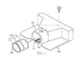
- FIG. 4is a perspective view schematically showing a structure of fastening optical lenses in an optical scanner according to an embodiment of the present invention.
- FIG. 5is a cross-sectional view schematically showing a structure of fastening adjustable optical lenses, after fabricated, in an optical scanner according to an embodiment of the present invention.
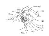
- FIG. 6is an exploded perspective view schematically showing a structure of fastening adjustable optical lenses by a fastening cover and screws in a conventional optical scanner according to an embodiment of the present invention.
- FIG. 3there is a scanning chassis of a conventional optical scanner.
- a light source 1100 , a reflector group 1400 , an optical-lens group 1510 , and an optical sensor, such as charged couple device (CCD) 1600are mounted in a case 1700 of the scanning chassis.
- CCDcharged couple device
- the reflector group 1400is composed of many reflectors 1401 , 1402 , 1403 that reflect the image of the document 1200 to transmit it to the optical-lens group 1510 .
- the optical-lens group 1510can receive the image, transmitted by the reflector group 1400 , of the document 1200 and can form the image onto the charged couple device 1600 .
- the apparatus for fastening adjustable optical lensesis provided with an optical-lens pedestal 1710 , integrally formed in the case 1700 , and a fastening cover 1520 .
- the optical-lens pedestal 1710is located between the optical sensor 1600 and the reflector group 1400 .
- the optical-lens pedestal 1710has a channel 1719 and the two sides of the channel 1719 are open. There are many grooves 1711 on the side wall of the channel 1719 .
- the optical lens 1511 , 1512 , 1513 of the optical-lens group 1510can be respectively mounted on the grooves 1711 and the relative position of the optical lens 1511 , 1512 , 1513 can be precisely adjusted.
- the optical-lens group 1510is located between the optical sensor 1600 and the reflector group 1400 .
- the optical-lens group 1510can receive the image of the document and can form the image onto the optical sensor 1600 .
- the fastening cover 1520is fixed on the optical-lens pedestal 1710 so that the optical lenses 1511 , 1512 , 1513 are firmly fixed between the optical-lens 1710 and the fastening cover 1520 .
- the fastening cover 1520is provided with two hooks 1522 that can be respectively coupled with two hooking ditches 1712 of the optical-lens pedestal 1710 so that the fastening cover 1520 can be firmly fixed on the optical-lens pedestal 1710 .
- the fastening coveris fixed on the optical-lens pedestal by means of hooks and hooking ditches.
- the inventionis not limited to the above application.
- screws 1800can be screwed through first screw holes 1524 of a fastening cover 1520 and then into second screw holes 1713 of a optical-lens pedestal 1710 so that the fastening cover 1520 can be firmly fixed or the optical-lens pedestal 1710 .
- the fastening covercan be fixed on the optical-lens pedestal by coating an adhesive. Besides, if the optical lenses can be firmly fixed on the optical-lens pedestal, even a fastening cover can be saved.
- the optical-lens pedestal 1710 and the grooves 1711are directly formed on the case 1700 of the scanning chassis when the case 1700 of the scanning chassis is formed using a process of injection molding.
- the position where the grooves 1711 are formed on the optical-lens pedestal 1710can be regulated by adjusting the mold. Therefore, the grooves 1711 can be precisely formed on the optical-lens pedestal 1710 and the relative position of the optical lenses 1511 , 1512 , 1513 mounted on the grooves 1711 can be precisely controlled. As a result, the time of adjusting the optical lenses 1511 , 1512 , 1513 can be saved and the number of parts can be decreased.
- the channel 1719 of the optical-lens pedestal 1710can be designed as a half-round shape.
- the inventionis not limited to the above-mentioned application.
- the channel of the optical-lens pedestalcan be designed as various cross-sectional shapes.
- the fastening cover 1520in order to match the shape of the optical lenses 1511 , 1512 , 1513 , the fastening cover 1520 can be designed with a channel 1529 cross-sectionally shaped as half-round.
- the inventionis not limited to the above-mentioned application.
- the channel of the fastening covercan be designed as various cross-sectional shapes.
- the number of the groovesis not limited to three as shown in FIG. 3, FIG. 4, FIG. 5, FIG. 6, but any number of the grooves can be formed on the optical-lens pedestal.
- the type of the groovesis not limited, but any type of the grooves can be formed on the optical-lens pedestal. As a result, the types and the number of the optical lenses can be changed according to requirements.
- the present inventionhas the following advantages:
- the casecan be integrally formed with the optical-lens pedestal, so the number of parts can be decreased and the cost can drop off.
- the groovescan be precisely formed on the optical-lens pedestal and the relative position of the optical lenses mounted on the grooves can be precisely controlled. As a result, the time of adjusting the optical lenses can be saved.
- the types and the number of the optical lensescan be changed according to requirements.
Landscapes
- Physics & Mathematics (AREA)
- General Physics & Mathematics (AREA)
- Optics & Photonics (AREA)
- Engineering & Computer Science (AREA)
- Multimedia (AREA)
- Signal Processing (AREA)
- Facsimile Heads (AREA)
- Facsimile Scanning Arrangements (AREA)
Abstract
Description
- 1. Field of the Invention[0001]
- The invention relates in general to a method and an apparatus for fastening adjustable optical lenses. The method and the apparatus can be adapted for an optical scanner.[0002]
- 2. Description of the Related Art[0003]
- With improvement of software and hardware, a scanner has become a requisite for many computer users. A scanner can scan word or image data of a document, a magazine, a book or a picture, and can input a computer to process. Among various scanners, the most popular one is flatbed scanner where there is a scanning chassis mounted under a transparent flatbed and capable of reciprocating to scan a document placed on the transparent flatbed. The scanning chassis can not move by itself and it must be driven by a transmission, such as a servomotor, gear wheels, a belt and so on. When a flatbed scanner is used to scan a document, the document is placed on the transparent flatbed, and then a document cover covers the document to press the document so that the document can evenly lie on the transparent flatbed. Next, the scanner can scan the document.[0004]
- As shown in FIG. 1, there is a scanning chassis of a conventional optical scanner. A[0005]
light source 100, areflector group 400, an optical-lens assembly 500, and an optical sensor, such as charged couple device (CCD)600, are mounted in acase 700 of the scanning chassis. During scanning, after thelight source 100 illuminates adocument 200, an image of thedocument 200 can be obtained. Thereflector group 400 is composed ofmany reflectors document 200 to transmit it to the optical-lens assembly 500. The optical-lens assembly 500 can receive the image, transmitted by thereflector group 400, of thedocument 200 and can form the image onto thecharged couple device 600. - As shown in FIG. 2, the conventional optical-[0006]
lens assembly 500 includes an optical-lens group 510, composed of manyoptical lenses lens sleeve 520 where the optical-lens group 510 is mounted. Before the fabrication of the optical-lens assembly 500 is completed, the adjustment of the relative positions betweenoptical lenses lens assembly 500 is directly mounted on around sleeve 710 of thecase 700 by a method for coordinating a shaft and a hole. After the adjustment of the distance between the optical-lens assembly 500 and thecharged couple device 600 is completed, a process of coating an adhesive or that of screwing screws is used to fix the optical-lens assembly 500 on theround sleeve 710. - As above mentioned, the method for fabricating the conventional optical-[0007]
lens assembly 500 includes the adjustment of theoptical lenses lens sleeve 520 and further includes the adjustment of the distance between the optical-lens assembly 500 and thecharged couple device 600 when the optical-lens assembly 500 is mounted on theround sleeve 710. Therefore, the method for fabricating the conventional optical-lens assembly 500 needs many adjusting processes, so the time and cost for fabricating it dramatically increases. - Accordingly, an objective of the present invention is to provide an apparatus for fastening adjustable optical lenses. The apparatus can be mounted in a scanning chassis of an optical scanner and an optical-lens group can be mounted on the apparatus. Many grooves where many optical lenses are mounted are directly formed on a case of the scanning chassis when the case of the scanning chassis is formed using a process of injection molding. As a result, the optical-lens group can be directly fixed on the case of the scanning chassis. Therefore, the types and the number of the optical lenses can be changed according to requirements. In addition, the number of parts is decreased and the time for adjusting optical lenses is saved.[0008]
- To achieve the foregoing and other objectives, the present invention provides a method for fastening adjustable optical lenses. The method is suited for a scanning chassis and is used for fastening an optical-lens group. The scanning chassis includes a case, a light source, a reflector group and an optical sensor, wherein the light source, the reflector group and the optical sensor are mounted in the case. The light source is used for illuminating a document and an image of the document is obtained. The reflector group reflects the image of the document to transmit it to the optical sensor through the optical-lens group. The method for fastening adjustable optical lenses includes the following steps.[0009]
- An optical-lens pedestal is formed in the case and the optical-lens pedestal has at least one groove. The optical-lens- group is mounted on the groove and located between the optical sensor and the reflector group. The optical-lens group can receive the image of the document and can form the image onto the optical sensor.[0010]
- According to a preferred embodiment of the present invention, the optical-lens pedestal is integrally formed in the case. Besides, the method further includes fixing a fastening cover over the optical-lens pedestal so that the optical-lens group is fixed between the optical-lens pedestal and the fastening cover. The fastening cover is fixed on the optical-lens pedestal by means of hooks or screws.[0011]
- To achieve the foregoing and other objectives, the present invention provides an apparatus for fastening adjustable optical lenses. The apparatus is suited for a scanning chassis and is used for fastening an optical-lens group. The scanning chassis includes a case, a light source, a reflector group and an optical sensor, wherein the light source, the reflector group and the optical sensor are mounted in the case.[0012]
- The light source is used for illuminating a document and an image of the document is obtained. The reflector group reflects the image of the document to transmit it to the optical sensor through the optical-lens group. The optical-lens group includes at least one optical lens.[0013]
- The apparatus for fastening adjustable optical lenses includes an optical-lens pedestal integrally formed in the case. The optical-lens pedestal has a channel and the two sides of the channel are open. There is at least one groove on the side wall of the channel. The optical lens of the optical-lens group can be mounted on the groove and the optical-lens group is located between the optical sensor and the reflector group. The optical-lens group can receive the image of the document and can form the image onto the optical sensor.[0014]
- To achieve the foregoing and other objectives, the present invention further provides an adjustable optical scanning chassis. The adjustable optical scanning chassis includes a case, a light source, a reflector group, an optical sensor, an optical-lens group and an optical-lens pedestal. The light source is mounted in the case and used for illuminating a document so that an image of the document is obtained. The optical sensor is mounted in the case and used for receiving the image of the document. The optical-lens group is mounted in the case and has at least one optical lens. The reflector group is mounted in the case and reflects the image of the document to transmit it to the optical sensor through the optical-lens group. The optical-lens pedestal is located in the case. The optical-lens pedestal has a channel and the two sides of the channel are open. There is at least one groove on the side wall of the channel. The optical lens of the optical-lens group can be mounted on the groove and the optical-lens group is located between the optical sensor and the reflector group. The optical-lens group can receive the image of the document and can form the image onto the optical sensor.[0015]
- According to a preferred embodiment of the present invention, the optical-lens pedestal is integrally formed in the case. The shape of the optical-lens pedestal matches that of the optical lens. Besides, the apparatus further includes a fastening cover fixed over the optical-lens pedestal so that the optical-lens group is fixed between the optical-lens pedestal and the fastening cover.[0016]
- According to the feature of the invention, many grooves where many optical lenses are mounted are directly formed on a case of a scanning chassis when the case of the scanning chassis is formed using a process of injection molding. As a result, the optical-lens group can be directly fixed on the case of the scanning chassis. Therefore, the number of parts is decreased and the time for adjusting optical lenses is saved.[0017]
- According to the feature of the invention, because many optical lenses can be mounted on groves that are directly formed on a case of the scanning chassis, the types and the number of the optical lenses can be changed according to.[0018]
- Both the foregoing general description and the following detailed description are exemplary and explanatory only and are not restrictive of the invention, as claimed. It is to be understood that both the foregoing general description and the following detailed description are exemplary, and are intended to provide further explanation of the invention as claimed.[0019]
- The accompanying drawings are included to provide a further understanding of the invention, and are incorporated in and constitute a part of this specification. The drawings illustrate embodiments of the invention and, together with the description, serve to explain the principles of the invention. A simple description of the drawings is as follows.[0020]
- FIG. 1 is a cross-sectional view schematically showing a conventional optical scanner.[0021]
- FIG. 2 is an exploded perspective view schematically showing a structure of fastening an optical-lens assembly in a conventional optical scanner.[0022]
- FIG. 3 is a cross-sectional view schematically showing an optical scanner according to an embodiment of the present invention.[0023]
- FIG. 4 is a perspective view schematically showing a structure of fastening optical lenses in an optical scanner according to an embodiment of the present invention.[0024]
- FIG. 5 is a cross-sectional view schematically showing a structure of fastening adjustable optical lenses, after fabricated, in an optical scanner according to an embodiment of the present invention.[0025]
- FIG. 6 is an exploded perspective view schematically showing a structure of fastening adjustable optical lenses by a fastening cover and screws in a conventional optical scanner according to an embodiment of the present invention.[0026]
- Referring to FIG. 3, there is a scanning chassis of a conventional optical scanner. A light source[0027]1100, a reflector group1400, an optical-
lens group 1510, and an optical sensor, such as charged couple device (CCD)1600, are mounted in acase 1700 of the scanning chassis. During scanning, after the light source1100 illuminates a document1200, an image of the document1200 can be obtained. The reflector group1400 is composed of many reflectors1401,1402,1403 that reflect the image of the document1200 to transmit it to the optical-lens group 1510. The optical-lens group 1510 can receive the image, transmitted by the reflector group1400, of the document1200 and can form the image onto the charged couple device1600. - In the following, a method for fastening adjustable optical lenses is described. As shown in FIG. 3, FIG. 4 and FIG. 5, first, the apparatus for fastening adjustable optical lenses is provided with an optical-[0028]
lens pedestal 1710, integrally formed in thecase 1700, and afastening cover 1520. The optical-lens pedestal 1710 is located between the optical sensor1600 and the reflector group1400. The optical-lens pedestal 1710 has achannel 1719 and the two sides of thechannel 1719 are open. There aremany grooves 1711 on the side wall of thechannel 1719. Next, theoptical lens lens group 1510 can be respectively mounted on thegrooves 1711 and the relative position of theoptical lens lens group 1510 is located between the optical sensor1600 and the reflector group1400. The optical-lens group 1510 can receive the image of the document and can form the image onto the optical sensor1600. Following, thefastening cover 1520 is fixed on the optical-lens pedestal 1710 so that theoptical lenses lens 1710 and thefastening cover 1520. Thefastening cover 1520 is provided with twohooks 1522 that can be respectively coupled with two hookingditches 1712 of the optical-lens pedestal 1710 so that thefastening cover 1520 can be firmly fixed on the optical-lens pedestal 1710. - In the above description, the fastening cover is fixed on the optical-lens pedestal by means of hooks and hooking ditches. However, the invention is not limited to the above application. As shown in FIG. 6,[0029]
screws 1800 can be screwed throughfirst screw holes 1524 of afastening cover 1520 and then into second screw holes1713 of a optical-lens pedestal 1710 so that thefastening cover 1520 can be firmly fixed or the optical-lens pedestal 1710. Otherwise, the fastening cover can be fixed on the optical-lens pedestal by coating an adhesive. Besides, if the optical lenses can be firmly fixed on the optical-lens pedestal, even a fastening cover can be saved. - The optical-[0030]
lens pedestal 1710 and thegrooves 1711 are directly formed on thecase 1700 of the scanning chassis when thecase 1700 of the scanning chassis is formed using a process of injection molding. The position where thegrooves 1711 are formed on the optical-lens pedestal 1710 can be regulated by adjusting the mold. Therefore, thegrooves 1711 can be precisely formed on the optical-lens pedestal 1710 and the relative position of theoptical lenses grooves 1711 can be precisely controlled. As a result, the time of adjusting theoptical lenses - In the above embodiment, according to the cross-sectional shape, such as a shape as shown in FIG. 4, of the[0031]
optical lenses channel 1719 of the optical-lens pedestal 1710 can be designed as a half-round shape. However, the invention is not limited to the above-mentioned application. According to the various cross-sectional shapes of the optical lenses, the channel of the optical-lens pedestal can be designed as various cross-sectional shapes. - Accordingly, as shown in FIG. 4, in order to match the shape of the[0032]
optical lenses fastening cover 1520 can be designed with achannel 1529 cross-sectionally shaped as half-round. However, the invention is not limited to the above-mentioned application. According to the various cross-sectional shapes of the optical lenses, the channel of the fastening cover can be designed as various cross-sectional shapes. - In addition, the number of the grooves is not limited to three as shown in FIG. 3, FIG. 4, FIG. 5, FIG. 6, but any number of the grooves can be formed on the optical-lens pedestal. Besides, the type of the grooves is not limited, but any type of the grooves can be formed on the optical-lens pedestal. As a result, the types and the number of the optical lenses can be changed according to requirements.[0033]
- To sum up, the present invention has the following advantages:[0034]
- 1. According to the present invention, the case can be integrally formed with the optical-lens pedestal, so the number of parts can be decreased and the cost can drop off.[0035]
- 2. According to the present invention, the grooves can be precisely formed on the optical-lens pedestal and the relative position of the optical lenses mounted on the grooves can be precisely controlled. As a result, the time of adjusting the optical lenses can be saved.[0036]
- 3. According to the present invention, the types and the number of the optical lenses can be changed according to requirements.[0037]
- It will be apparent to those skilled in the art that various modifications and variations can be made to the structure of the present invention without departing from the scope or spirit of the invention. In view of the foregoing, it is intended that the present invention cover modifications and variations of this invention provided they fall within the scope of the following claims and their equivalents.[0038]
Claims (17)
Priority Applications (1)
| Application Number | Priority Date | Filing Date | Title |
|---|---|---|---|
| US10/063,433US7333248B2 (en) | 2002-04-23 | 2002-04-23 | Method and apparatus for fastening adjustable optical lenses |
Applications Claiming Priority (1)
| Application Number | Priority Date | Filing Date | Title |
|---|---|---|---|
| US10/063,433US7333248B2 (en) | 2002-04-23 | 2002-04-23 | Method and apparatus for fastening adjustable optical lenses |
Publications (2)
| Publication Number | Publication Date |
|---|---|
| US20030197899A1true US20030197899A1 (en) | 2003-10-23 |
| US7333248B2 US7333248B2 (en) | 2008-02-19 |
Family
ID=29214366
Family Applications (1)
| Application Number | Title | Priority Date | Filing Date |
|---|---|---|---|
| US10/063,433Expired - Fee RelatedUS7333248B2 (en) | 2002-04-23 | 2002-04-23 | Method and apparatus for fastening adjustable optical lenses |
Country Status (1)
| Country | Link |
|---|---|
| US (1) | US7333248B2 (en) |
Cited By (1)
| Publication number | Priority date | Publication date | Assignee | Title |
|---|---|---|---|---|
| EP1775616A1 (en)* | 2005-10-14 | 2007-04-18 | Sharp Kabushiki Kaisha | Optical component module and camera module |
Families Citing this family (1)
| Publication number | Priority date | Publication date | Assignee | Title |
|---|---|---|---|---|
| WO2008013527A1 (en)* | 2006-07-26 | 2008-01-31 | Hewlett-Packard Development Company, L.P. | Segmented reflective optical system |
Citations (9)
| Publication number | Priority date | Publication date | Assignee | Title |
|---|---|---|---|---|
| US4260880A (en)* | 1979-12-12 | 1981-04-07 | Key Tronic Corporation | Optical character scanner |
| US5343853A (en)* | 1991-09-20 | 1994-09-06 | Fuji Photo Optical Co., Ltd. | Side-looking type electronic endoscope which allows manipulating tool to be inserted thereinto |
| US5627589A (en)* | 1991-10-07 | 1997-05-06 | Nikon Corporation | Imaging apparatus with CCD holders |
| US5663558A (en)* | 1994-07-07 | 1997-09-02 | Brother Kogyo Kabushiki Kaisha | Optical beam scanning unit with slit for producing horizontal synchronizing signal |
| US5724159A (en)* | 1993-04-21 | 1998-03-03 | Mitsubishi Denki Kabushiki Kaisha | Image reading device provided with structural features for fixing the reading unit during transport |
| US20020024709A1 (en)* | 1998-11-07 | 2002-02-28 | Jenn-Tsair Tsai | Scanner photoelectric module with adjustable lens and charge-coupling device |
| US20020057467A1 (en)* | 2000-11-13 | 2002-05-16 | Brother Kogyo Kabushiki Kaisha | Optical element supporting plate |
| US6444978B1 (en)* | 1999-09-17 | 2002-09-03 | Shimadzu Corporation | Mass spectrometer having lens unit supported with springs |
| US20030111588A1 (en)* | 2001-12-18 | 2003-06-19 | Pao-Jung Chen | Near-contact optical touch-screen sensor module |
Family Cites Families (4)
| Publication number | Priority date | Publication date | Assignee | Title |
|---|---|---|---|---|
| JPS58105668A (en)* | 1981-12-18 | 1983-06-23 | Fujitsu Ltd | line sensor |
| JPS6039612A (en)* | 1983-08-12 | 1985-03-01 | Minolta Camera Co Ltd | Focus detector of camera |
| JP2899516B2 (en)* | 1993-12-20 | 1999-06-02 | 株式会社ピーエフユー | Image reading device |
| JPH11281357A (en)* | 1998-03-29 | 1999-10-15 | Yasaka:Kk | Inclination detecting structure of laser marking apparatus |
- 2002
- 2002-04-23USUS10/063,433patent/US7333248B2/ennot_activeExpired - Fee Related
Patent Citations (9)
| Publication number | Priority date | Publication date | Assignee | Title |
|---|---|---|---|---|
| US4260880A (en)* | 1979-12-12 | 1981-04-07 | Key Tronic Corporation | Optical character scanner |
| US5343853A (en)* | 1991-09-20 | 1994-09-06 | Fuji Photo Optical Co., Ltd. | Side-looking type electronic endoscope which allows manipulating tool to be inserted thereinto |
| US5627589A (en)* | 1991-10-07 | 1997-05-06 | Nikon Corporation | Imaging apparatus with CCD holders |
| US5724159A (en)* | 1993-04-21 | 1998-03-03 | Mitsubishi Denki Kabushiki Kaisha | Image reading device provided with structural features for fixing the reading unit during transport |
| US5663558A (en)* | 1994-07-07 | 1997-09-02 | Brother Kogyo Kabushiki Kaisha | Optical beam scanning unit with slit for producing horizontal synchronizing signal |
| US20020024709A1 (en)* | 1998-11-07 | 2002-02-28 | Jenn-Tsair Tsai | Scanner photoelectric module with adjustable lens and charge-coupling device |
| US6444978B1 (en)* | 1999-09-17 | 2002-09-03 | Shimadzu Corporation | Mass spectrometer having lens unit supported with springs |
| US20020057467A1 (en)* | 2000-11-13 | 2002-05-16 | Brother Kogyo Kabushiki Kaisha | Optical element supporting plate |
| US20030111588A1 (en)* | 2001-12-18 | 2003-06-19 | Pao-Jung Chen | Near-contact optical touch-screen sensor module |
Cited By (3)
| Publication number | Priority date | Publication date | Assignee | Title |
|---|---|---|---|---|
| EP1775616A1 (en)* | 2005-10-14 | 2007-04-18 | Sharp Kabushiki Kaisha | Optical component module and camera module |
| US20070091477A1 (en)* | 2005-10-14 | 2007-04-26 | Sharp Kabushiki Kaisha | Optical component module and camera module |
| US7436606B2 (en) | 2005-10-14 | 2008-10-14 | Sharp Kabushiki Kaisha | Optical component module and camera module |
Also Published As
| Publication number | Publication date |
|---|---|
| US7333248B2 (en) | 2008-02-19 |
Similar Documents
| Publication | Publication Date | Title |
|---|---|---|
| US6188527B1 (en) | LED array PCB with adhesive rod lens | |
| US8345325B2 (en) | Segmented reflective optical system | |
| US7242502B2 (en) | Optical device of scanner | |
| USRE39689E1 (en) | Apparatus for securing CCD board at a fixed position within a range of motion | |
| US7333248B2 (en) | Method and apparatus for fastening adjustable optical lenses | |
| US20080062530A1 (en) | Lens unit and image reading apparatus using the same | |
| US7847983B2 (en) | Image reading apparatus | |
| US5895914A (en) | Scanner capable of scanning penetrative document and reflective document with single lamp | |
| US6661588B1 (en) | Objective lens anti-shock adjustment device | |
| US8488208B2 (en) | Optical module, an image reader and an assembling method of an optical module | |
| US20020109864A1 (en) | Drive unit, method of producing drive unit, running body moving unit, image reading apparatus, and imaging apparatus | |
| US6373601B1 (en) | Image scanner | |
| US20020040965A1 (en) | Scanner with light directing channel | |
| US20080094679A1 (en) | Light source module and scanning module using the same | |
| JPS62279772A (en) | Digital picture forming device | |
| USRE40592E1 (en) | Mounting apparatus for optical sensor having screw piles with annular fitting boards | |
| US20030057349A1 (en) | Height adjustment structure | |
| US20040004669A1 (en) | Light-focusing for image-gathering device and method | |
| CN1445577A (en) | Method for fixing adjustable optical lens group and its structure | |
| US20030197911A1 (en) | Optical lens of optical scanner | |
| JPH0821939A (en) | Position adjustment device for optical axis of lens | |
| US7439490B2 (en) | Reading-line adjusting device of image scanner | |
| USRE41818E1 (en) | Installation for improving a scanning range of scanner along an axial direction of a light source | |
| US20040136085A1 (en) | Variable-curvature lens system and method for adjusting curvature thereof | |
| CN2514363Y (en) | Linear fine tuning device |
Legal Events
| Date | Code | Title | Description |
|---|---|---|---|
| AS | Assignment | Owner name:UMAX DATA SYSTEMS, INC., TAIWAN Free format text:ASSIGNMENT OF ASSIGNORS INTEREST;ASSIGNORS:TSENG, JEN-SHOU;HUANG, CHIH-WEN;HSU, CHUAN-YU;REEL/FRAME:012617/0436;SIGNING DATES FROM 20020414 TO 20020416 | |
| AS | Assignment | Owner name:VEUTRON CORPORATION, TAIWAN Free format text:CHANGE OF NAME;ASSIGNOR:UMAX DATA SYSTEMS INC.;REEL/FRAME:016800/0203 Effective date:20021029 | |
| AS | Assignment | Owner name:TRANSPACIFIC IP, LTD.,TAIWAN Free format text:ASSIGNMENT OF ASSIGNORS INTEREST;ASSIGNOR:VEUTRON CORPORATION;REEL/FRAME:017564/0747 Effective date:20050706 Owner name:TRANSPACIFIC IP, LTD., TAIWAN Free format text:ASSIGNMENT OF ASSIGNORS INTEREST;ASSIGNOR:VEUTRON CORPORATION;REEL/FRAME:017564/0747 Effective date:20050706 | |
| STCF | Information on status: patent grant | Free format text:PATENTED CASE | |
| AS | Assignment | Owner name:TRANSPACIFIC SYSTEMS, LLC, DELAWARE Free format text:ASSIGNMENT OF ASSIGNORS INTEREST;ASSIGNOR:TRANSPACIFIC IP LTD.;REEL/FRAME:023107/0267 Effective date:20090618 Owner name:TRANSPACIFIC SYSTEMS, LLC,DELAWARE Free format text:ASSIGNMENT OF ASSIGNORS INTEREST;ASSIGNOR:TRANSPACIFIC IP LTD.;REEL/FRAME:023107/0267 Effective date:20090618 | |
| CC | Certificate of correction | ||
| FPAY | Fee payment | Year of fee payment:4 | |
| AS | Assignment | Owner name:TITUSVILLE CANAVERAL LLC, DELAWARE Free format text:MERGER;ASSIGNOR:TRANSPACIFIC SYSTEMS, LLC;REEL/FRAME:030628/0681 Effective date:20130213 | |
| AS | Assignment | Owner name:INTELLECTUAL VENTURES I LLC, DELAWARE Free format text:MERGER;ASSIGNOR:TITUSVILLE CANAVERAL LLC;REEL/FRAME:030639/0330 Effective date:20130214 | |
| FPAY | Fee payment | Year of fee payment:8 | |
| FEPP | Fee payment procedure | Free format text:MAINTENANCE FEE REMINDER MAILED (ORIGINAL EVENT CODE: REM.); ENTITY STATUS OF PATENT OWNER: LARGE ENTITY | |
| LAPS | Lapse for failure to pay maintenance fees | Free format text:PATENT EXPIRED FOR FAILURE TO PAY MAINTENANCE FEES (ORIGINAL EVENT CODE: EXP.); ENTITY STATUS OF PATENT OWNER: LARGE ENTITY | |
| STCH | Information on status: patent discontinuation | Free format text:PATENT EXPIRED DUE TO NONPAYMENT OF MAINTENANCE FEES UNDER 37 CFR 1.362 | |
| FP | Expired due to failure to pay maintenance fee | Effective date:20200219 |