US20030178228A1 - Method for scalable architectures in stackable three-dimentsional integrated circuits and electronics - Google Patents
Method for scalable architectures in stackable three-dimentsional integrated circuits and electronicsDownload PDFInfo
- Publication number
- US20030178228A1 US20030178228A1US10/391,781US39178103AUS2003178228A1US 20030178228 A1US20030178228 A1US 20030178228A1US 39178103 AUS39178103 AUS 39178103AUS 2003178228 A1US2003178228 A1US 2003178228A1
- Authority
- US
- United States
- Prior art keywords
- coupled
- input
- output
- connector
- layer
- Prior art date
- Legal status (The legal status is an assumption and is not a legal conclusion. Google has not performed a legal analysis and makes no representation as to the accuracy of the status listed.)
- Granted
Links
Images


Classifications
- H—ELECTRICITY
- H05—ELECTRIC TECHNIQUES NOT OTHERWISE PROVIDED FOR
- H05K—PRINTED CIRCUITS; CASINGS OR CONSTRUCTIONAL DETAILS OF ELECTRIC APPARATUS; MANUFACTURE OF ASSEMBLAGES OF ELECTRICAL COMPONENTS
- H05K1/00—Printed circuits
- H05K1/02—Details
- H05K1/11—Printed elements for providing electric connections to or between printed circuits
- H—ELECTRICITY
- H01—ELECTRIC ELEMENTS
- H01L—SEMICONDUCTOR DEVICES NOT COVERED BY CLASS H10
- H01L25/00—Assemblies consisting of a plurality of semiconductor or other solid state devices
- H01L25/03—Assemblies consisting of a plurality of semiconductor or other solid state devices all the devices being of a type provided for in a single subclass of subclasses H10B, H10D, H10F, H10H, H10K or H10N, e.g. assemblies of rectifier diodes
- H01L25/04—Assemblies consisting of a plurality of semiconductor or other solid state devices all the devices being of a type provided for in a single subclass of subclasses H10B, H10D, H10F, H10H, H10K or H10N, e.g. assemblies of rectifier diodes the devices not having separate containers
- H01L25/065—Assemblies consisting of a plurality of semiconductor or other solid state devices all the devices being of a type provided for in a single subclass of subclasses H10B, H10D, H10F, H10H, H10K or H10N, e.g. assemblies of rectifier diodes the devices not having separate containers the devices being of a type provided for in group H10D89/00
- H01L25/0657—Stacked arrangements of devices
- H—ELECTRICITY
- H01—ELECTRIC ELEMENTS
- H01L—SEMICONDUCTOR DEVICES NOT COVERED BY CLASS H10
- H01L23/00—Details of semiconductor or other solid state devices
- H01L23/52—Arrangements for conducting electric current within the device in operation from one component to another, i.e. interconnections, e.g. wires, lead frames
- H01L23/522—Arrangements for conducting electric current within the device in operation from one component to another, i.e. interconnections, e.g. wires, lead frames including external interconnections consisting of a multilayer structure of conductive and insulating layers inseparably formed on the semiconductor body
- H01L23/5226—Via connections in a multilevel interconnection structure
- H—ELECTRICITY
- H05—ELECTRIC TECHNIQUES NOT OTHERWISE PROVIDED FOR
- H05K—PRINTED CIRCUITS; CASINGS OR CONSTRUCTIONAL DETAILS OF ELECTRIC APPARATUS; MANUFACTURE OF ASSEMBLAGES OF ELECTRICAL COMPONENTS
- H05K1/00—Printed circuits
- H05K1/02—Details
- H05K1/11—Printed elements for providing electric connections to or between printed circuits
- H05K1/115—Via connections; Lands around holes or via connections
- H—ELECTRICITY
- H10—SEMICONDUCTOR DEVICES; ELECTRIC SOLID-STATE DEVICES NOT OTHERWISE PROVIDED FOR
- H10D—INORGANIC ELECTRIC SEMICONDUCTOR DEVICES
- H10D87/00—Integrated devices comprising both bulk components and either SOI or SOS components on the same substrate
- H—ELECTRICITY
- H10—SEMICONDUCTOR DEVICES; ELECTRIC SOLID-STATE DEVICES NOT OTHERWISE PROVIDED FOR
- H10D—INORGANIC ELECTRIC SEMICONDUCTOR DEVICES
- H10D88/00—Three-dimensional [3D] integrated devices
- H—ELECTRICITY
- H01—ELECTRIC ELEMENTS
- H01L—SEMICONDUCTOR DEVICES NOT COVERED BY CLASS H10
- H01L2225/00—Details relating to assemblies covered by the group H01L25/00 but not provided for in its subgroups
- H01L2225/03—All the devices being of a type provided for in the same main group of the same subclass of class H10, e.g. assemblies of rectifier diodes
- H01L2225/04—All the devices being of a type provided for in the same main group of the same subclass of class H10, e.g. assemblies of rectifier diodes the devices not having separate containers
- H01L2225/065—All the devices being of a type provided for in the same main group of the same subclass of class H10
- H01L2225/06503—Stacked arrangements of devices
- H01L2225/06513—Bump or bump-like direct electrical connections between devices, e.g. flip-chip connection, solder bumps
- H—ELECTRICITY
- H01—ELECTRIC ELEMENTS
- H01L—SEMICONDUCTOR DEVICES NOT COVERED BY CLASS H10
- H01L2225/00—Details relating to assemblies covered by the group H01L25/00 but not provided for in its subgroups
- H01L2225/03—All the devices being of a type provided for in the same main group of the same subclass of class H10, e.g. assemblies of rectifier diodes
- H01L2225/04—All the devices being of a type provided for in the same main group of the same subclass of class H10, e.g. assemblies of rectifier diodes the devices not having separate containers
- H01L2225/065—All the devices being of a type provided for in the same main group of the same subclass of class H10
- H01L2225/06503—Stacked arrangements of devices
- H01L2225/06541—Conductive via connections through the device, e.g. vertical interconnects, through silicon via [TSV]
- H01L2225/06544—Design considerations for via connections, e.g. geometry or layout
- H—ELECTRICITY
- H01—ELECTRIC ELEMENTS
- H01L—SEMICONDUCTOR DEVICES NOT COVERED BY CLASS H10
- H01L2225/00—Details relating to assemblies covered by the group H01L25/00 but not provided for in its subgroups
- H01L2225/03—All the devices being of a type provided for in the same main group of the same subclass of class H10, e.g. assemblies of rectifier diodes
- H01L2225/04—All the devices being of a type provided for in the same main group of the same subclass of class H10, e.g. assemblies of rectifier diodes the devices not having separate containers
- H01L2225/065—All the devices being of a type provided for in the same main group of the same subclass of class H10
- H01L2225/06503—Stacked arrangements of devices
- H01L2225/06555—Geometry of the stack, e.g. form of the devices, geometry to facilitate stacking
- H01L2225/06565—Geometry of the stack, e.g. form of the devices, geometry to facilitate stacking the devices having the same size and there being no auxiliary carrier between the devices
- H—ELECTRICITY
- H01—ELECTRIC ELEMENTS
- H01L—SEMICONDUCTOR DEVICES NOT COVERED BY CLASS H10
- H01L2924/00—Indexing scheme for arrangements or methods for connecting or disconnecting semiconductor or solid-state bodies as covered by H01L24/00
- H01L2924/0001—Technical content checked by a classifier
- H01L2924/0002—Not covered by any one of groups H01L24/00, H01L24/00 and H01L2224/00
- H—ELECTRICITY
- H01—ELECTRIC ELEMENTS
- H01L—SEMICONDUCTOR DEVICES NOT COVERED BY CLASS H10
- H01L2924/00—Indexing scheme for arrangements or methods for connecting or disconnecting semiconductor or solid-state bodies as covered by H01L24/00
- H01L2924/30—Technical effects
- H01L2924/301—Electrical effects
- H01L2924/3011—Impedance
- H—ELECTRICITY
- H05—ELECTRIC TECHNIQUES NOT OTHERWISE PROVIDED FOR
- H05K—PRINTED CIRCUITS; CASINGS OR CONSTRUCTIONAL DETAILS OF ELECTRIC APPARATUS; MANUFACTURE OF ASSEMBLAGES OF ELECTRICAL COMPONENTS
- H05K2201/00—Indexing scheme relating to printed circuits covered by H05K1/00
- H05K2201/09—Shape and layout
- H05K2201/09209—Shape and layout details of conductors
- H05K2201/09654—Shape and layout details of conductors covering at least two types of conductors provided for in H05K2201/09218 - H05K2201/095
- H05K2201/09709—Staggered pads, lands or terminals; Parallel conductors in different planes
- H—ELECTRICITY
- H05—ELECTRIC TECHNIQUES NOT OTHERWISE PROVIDED FOR
- H05K—PRINTED CIRCUITS; CASINGS OR CONSTRUCTIONAL DETAILS OF ELECTRIC APPARATUS; MANUFACTURE OF ASSEMBLAGES OF ELECTRICAL COMPONENTS
- H05K3/00—Apparatus or processes for manufacturing printed circuits
- H05K3/46—Manufacturing multilayer circuits
- H05K3/4611—Manufacturing multilayer circuits by laminating two or more circuit boards
Definitions
- layers of transistor circuitsmay be interconnected with coarser grain conductors such as coaxial lines, (C-4) solder pads, solder mounds, solder bumps, wire bounds, wire interconnects or embedded wiring as in U.S. patent application Ser. No. 20010033030; U.S. patent application No. 20010033509; U.S. patent application Ser. No. 20010005059; U.S. Pat. No. 5,495,397; U.S. Pat. No. 5,544,017; U.S. Pat. No. 5,778,529.
- coarser grain conductorssuch as coaxial lines, (C-4) solder pads, solder mounds, solder bumps, wire bounds, wire interconnects or embedded wiring
- Die stackinghas the potential to increase processing power, chip integration, operating speed and data storage density in the same planar area while minimizing global interconnect lengths. Reducing the stacking interval (distance between adjacent dies) in these technologies reduces wire lengths even further, resulting in reduced power consumption and increased logic speed. However, self-heating effects, alignment issues and circuit yield impose limits on the stack height. As designs move to three dimensions, new design techniques are required to maximize performance while minimizing design effort.
- An object of this inventionis to provide a method to reuse the same or similar integrated circuit design for each die in a vertically bonded stack of dies, and have the entire stack of dies function as an interconnected system.
- the methods describedenable scalable integrated circuit systems in which circuits on different die, in a vertical three-dimensional stack of dies, are identical. Only one mask set is required for the entire stack. The system scales directly as the level of stacking is increased while incurring no extra design effort as the stack height increases.
- FIG. 1is a cross section of a stack of dies using MIT Lincoln Laboratory's 3D Fully-Depleted Silicon-On-Insulator technology. This figure shows the orientation of an interdie-connector relative to the dies and associated transistor layers.
- FIG. 2illustrates a single die connector with two 3D via pads spaced equidistant on both sides of the 3D via conductor. It also shows the circuit symbol used to denote the die connector;
- FIG. 3illustrates how the die connector can be used to form connections between dies, where alternating dies are offset by the distance, d, between the 3D via conductor and 3D via pads. It also demonstrates the arrangement and connection of 3D via and 3D via pads for broadcasting a signal to all dies;
- FIG. 4illustrates a die connector array and modified die connectors
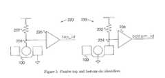
- FIG. 5illustrates passive top and bottom die identifier circuits that are present on all dies in the vertical stack of dies
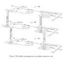
- FIG. 6presents various inter-die structures useful for signals, global clocks and power routing. Also shown are the circuits used to identify the top and bottom dies in the stack.
- FIG. 7illustrates circuits to address one die in a vertical stack of dies
- FIG. 8illustrates a one-bit slice of an interdie communications chain that communicates data between storage elements on adjacent dies.
- FIG. 9shows how the circuit in FIG. 7 appears in a stack of identical dies.
- FIG. 10shows how the circuit in FIG. 8 appears in a stack of identical dies.
- FIGS. 1 through 6 of the drawingslike numerals being used to refer to like and corresponding parts of the various drawings.
- the present inventioninvolves design techniques or methods that enable scalable integrated circuit systems.
- a single design and mask setis produced for one die, within a vertical three-dimensional stack of dies, and is reused for all dies with little or no design modification.
- the presented methodsincrease processing power, chip integration and data storage density in the same planar integrated circuit area with small additional design effort for the single design that is reused for all dies in the stack. These methods will significantly reduce the performance/productivity gap inherent with shrinking device geometries and increased system-on-chip integration.
- Vertical conductors or interdie vias 2are conductors that allow signals on adjacent dies to be coupled together.
- a compact 2.5- ⁇ m vertical conductor 2connects the top metal (M3) of the current die to bottom metal (M1) of the die above as in FIG. 1.
- design rulesdo not permit vertical conductors 2 to be directly stacked.
- the top metal M3is shown on top and the vertical conductors 2 are shown going upwards.
- the stacking interval, or distance between adjacent stack levels,is approximately 6.0 ⁇ m and stack levels are separated by an insulator.
- Stacked die architectures that use a repeated designrequire bi-directional vertical conductors 2 coupled with terminators 4 for those conductors.
- This structure, or connector 100consists of a vertical conductor 2 situated equally between two terminators 4 as shown in FIG. 2.
- An electrical connection 102can exist between each terminator 4 .
- the conditional connection 104 between the vertical conductor 2 and terminators 4 on the local dieis key for implementing various inter-die communication networks.
- This staggered alignment of alternating diesfacilitates the connection of signals from the current die to the die above, the die below or both dies. With one mask set and wafer type the wafers are aligned with the necessary offset, d, and then fused together.
- An extension 200 of the connector structure 100consists of four terminators 4 placed symmetrically around a vertical conductor 2 with an optional connection 104 .
- This structure 200can be used as elements in an array 210 as in FIG. 4. This facilitates inter-die routing of standard cells which do not have a preferred or fixed orientation and whose orientation could be changed by the computer-aided-design tools used for placement and routing.
- I/O cells and I/O padswhich may have to be rotated in 90° increments in the I/O pad ring, can use the connector array 210 . This is because the connector array 210 can be rotated in 90° increments and maintain same signal connectivity between two adjacent dies.
- top die identifying circuit 220consists of a connector 100 where the terminators 4 are grounded and the vertical conductor 2 is coupled to a weak pull-up device 222 , as shown in FIG. 5.
- the node 224 connected to the weak pull-up device 222is amplified by a buffer 226 to provide the top_id for the current die.
- a similar circuit 230is constructed to identify the bottom die. Thus any die below another die will have its identifier signal grounded, while the top die's identifier signal is pulled high.
- die identification circuit group 270 in FIG. 6die 110 will have its top identifier signal top_id asserted and die 114 will have its bottom identifier signal bottom_id asserted. All other top_id and bottom_id signals will remain unasserted.
- the static power consumed by this self-identifying schemeis very small (in the order of tens of ⁇ W per circuit layer).
- Other implementations of die identifier circuitsexist which do not consume static power. These identifier circuits use custom or standard cell library storage elements instead of resistors. However, they require an external control signal.
- a broadcasting circuit 250sends a signal to all dies within the stack. Examples of broadcast signals include global clocks, addresses, and control signals.
- a connector 100 with the vertical conductor 2 coupled 104 to its terminators 4will implement broadcasting, as in FIGS. 3 and 6. All metal layers in FIG. 3 are assumed to be connected with regular vias.
- a connector array 210provides a high-density, low-resistance, high current carrying connection 260 and is suitable for routing fixed-potentials between dies.
- Die addressingis the means by which one die is selected within the stack.
- the die addressing circuit 280shown in FIG. 7, uses the top die identifier signal top_id from the top die indentifier circuit 220 .
- the top_id signalis used as the select line for the 2-1 multiplexor 282 .
- Individual diescan be assigned unique addresses relative to the top die or bottom die in the stack. If top_id is asserted, the die_addr signal will be zero. Otherwise, die_addr will be equal to the output of the adder 284 that is present on the die above.
- a comparator 286compares the die_addr signal with the addr_in signal that is broadcasted to all dies with the broadcasting circuit 250 .
- top die 110has a die_addr of 0
- middle die 112has a die_addr of 1
- the bottom die 114has a die_addr of 2.
- thisdescribes a method of assigning die addresses where the top die sets its address to zero, increments the address by one and passes it down. The next die, because it is not the top die, will make the passed-in address its own, then increment it and pass it down. A die will respond when the input broadcast address addr_in matches the die address die_addr. Die addresses are precomputed allowing the input address to be immediately driven for faster address resolution.
- Inter-die networkscan be used to implement scan chains 290 , inter-processor communication or pipelined computation where information is passed from latches or registers 294 on one level of the stack to latches or registers on another level of the stack. Register 294 is clocked by a global signal clk that is broadcasted using a broadcast circuit 250 .
- FIG. 8shows a one-bit slice of an inter-die scan chain 290 .
- shift_inis coupled to in (an external signal) through a tristate buffer 292 .
- This tristate buffer 292is controlled by the result (top_id) of the top die identifier circuit 220 .
- the shift_out signalis coupled to the die below 112 through a connector 100 .
- shift_inis coupled to the die above 110 through the connector 100 and shift_out is coupled to the die below 114 through the connector 100 .
- shift_inis coupled to the die above 112 through the connector 100 and shift_out is coupled by a tristate buffer 296 to a broadcasting circuit 250 that conveys the data to the top of the stack 110 and then to a location external to the stack.
- the tristate buffer 296is controlled by the bottom_id signal generated by the bottom die identifier circuit 230 .
- the present inventioncan be adapted to any stackable integrated circuit technology that allows unrestricted or restricted vertical interconnections between adjacent dies.
- the method of aligning and connecting together like waferscan be applied to: stacked multi-chip modules, stacked printed circuit boards, three-dimensional systems packaging, stacked system modules, stacked circuit subassemblies or any other stacked three-dimensional array of electronic circuitry where like electronic circuitry is used for each level of the stack.
Landscapes
- Engineering & Computer Science (AREA)
- Microelectronics & Electronic Packaging (AREA)
- Power Engineering (AREA)
- Physics & Mathematics (AREA)
- Condensed Matter Physics & Semiconductors (AREA)
- General Physics & Mathematics (AREA)
- Computer Hardware Design (AREA)
- Semiconductor Integrated Circuits (AREA)
Abstract
Description
- This application claims priority from U.S. Application No. 60/365,807 file Mar. 21, 2002.[0001]
- Scalable electronic circuit system composed of stacked layers of the same or similar circuitry.[0002]
- Traditionally integrated circuits have been built in a planar fashion, with a single layer of transistors. New developments in manufacturing process technology allow wafers to be vertically stacked and fine-grained vertical conductors formed between circuits on adjacent dies [1, 2, 3, 4, 5, 6, 7]; U.S. Pat. No. 5,627,106; U.S. Pat. No. 5,877,034; U.S. Pat. No. 5,998,808; U.S. Pat. No. 6,185,122; U.S. Pat. No. 6,034,882. Alternatively, layers of transistor circuits may be interconnected with coarser grain conductors such as coaxial lines, (C-4) solder pads, solder mounds, solder bumps, wire bounds, wire interconnects or embedded wiring as in U.S. patent application Ser. No. 20010033030; U.S. patent application No. 20010033509; U.S. patent application Ser. No. 20010005059; U.S. Pat. No. 5,495,397; U.S. Pat. No. 5,544,017; U.S. Pat. No. 5,778,529.[0003]
- It can be useful for each die in a three-dimensional stack of dies to serve a unique purpose. Previous designs implemented in vertically stacked integrated circuit processes used individual mask layouts for each die in the stack [1, 5, 3, 4]; U.S. Pat. No. 5,998,808; U.S. Pat. No. 5,138,437. While extending these circuits to three-dimensions has the effect of reducing global interconnect length, they do little to alleviate the design effort and mask costs associated with each die.[0004]
- Recent innovations in three-dimensional memories stack separate layers of memory cells on top of a layer of peripheral circuits [7]; U.S. Pat. No. 6,185,122; U.S. Pat. No. 6,034,882; U.S. Pat. No. 5,487,031; U.S Pat. No. 5,375,085. However, in these designs, both the memory cell layers and the peripheral circuits must be present to provide random access data storage thus requiring at least two sets of layout masks. Furthermore, the three-dimensional techniques described do not apply to digital logic or digital logic coupled with memories.[0005]
- Die stacking has the potential to increase processing power, chip integration, operating speed and data storage density in the same planar area while minimizing global interconnect lengths. Reducing the stacking interval (distance between adjacent dies) in these technologies reduces wire lengths even further, resulting in reduced power consumption and increased logic speed. However, self-heating effects, alignment issues and circuit yield impose limits on the stack height. As designs move to three dimensions, new design techniques are required to maximize performance while minimizing design effort.[0006]
- [1] J. A. Burns et al., “Three-dimensional integrated circuits for low-power, high-bandwidth systems on a chip”, in[0007]Proc. IEEE Intl. Solid-State Circuits Conf., pp. 268-269, 453, February 2001.
- [2] J. A. Burns et al., “3D circuit integration technology for multiproject fabrication”, MIT Lincoln Laboratory, May 2001, DARPA PI Meeting.[0008]
- [3] Y. Akasaka, “Three-dimensional IC trends”,[0009]Proc. of the IEEE,vol. 74, n. 12, pp. 1703-1714, December 1986.
- [4] K. Banerjee, S. J. Souri, P. Kapur and K. C. Saraswat, “3-D ICs: A novel chip design for improving deep-submicrometer interconnect performance and systems-[0010]
TABLE 1 U.S. Patent Documents Patent No. Inventor Date 20010033509 Ahn, Kie Y. et al. Oct. 25, 2001 20010033030 Leedy, Glenn J. Oct. 25, 2001 6,185,122 Johnson, et al. Feb. 6, 2001 6,034,882 Johnson, et al. Mar. 7, 2000 20010005059 Koyanagi, Mitsumasa; et al. Jun. 28, 2001 5,998,808 Matsushita Dec. 7, 1999 5,138,437 Kumamoto Aug. 11, 1992 5,375,085 Gnade, et al. Dec. 20, 1994 5,487,031 Gnade, et al. Jan. 23, 1996 5,495,397 Davidson, et al. Feb. 27, 1996 5,877,034 Ramm, et al. Mar. 2, 1999 5,778,529 Beilin, et al. Jul. 14, 1998 5,627,106 Hsu May 6, 1997 5,544,017 Beilin, et al. Aug. 6, 1996 - [0011] Proc. of the IEEE,vol. 89, n. 5, pp. 602-633, May 2001.
- [5] K. Kioi et al., “Design and implementation of a 3D-LSI image sensing processor”,[0012]IEEE J. Solid-State Circuits, vol. 27, n. 8, pp. 1130-1140, Aug. 1992.
- [6] V. W. C. Chan, P. C. H. Chan and M. Chan, “Multiple layers of CMOS integrated circuits using recrysrallized silicon film”,[0013]IEEE Electron Device Letters,vol. 22, n. 2, pp. 77-79, February 2001.
- [7] T. H. Lee, “A vertical leap for microchips”,[0014]Scientific American,pp. 52-59, January 2002.
- An object of this invention is to provide a method to reuse the same or similar integrated circuit design for each die in a vertically bonded stack of dies, and have the entire stack of dies function as an interconnected system.[0015]
- It is a further object of this invention to provide such a method for arranging vertical conductors and terminators for coupling electrical signals between adjacent dies in the stack.[0016]
- It is a further object of this invention to provide such a method for offsetting dies for coupling electrical signals between adjacent dies in the stack.[0017]
- In light of the fact that electrical signals can communicate among others: data information, control information, addressing information; it is an object of this invention to provide such a method for communicating externally to, externally from or communicating between, dies in the stack.[0018]
- It is a further object of this invention to provide such a method for identifying the top die to define a communications boundary in a vertical stack of like dies.[0019]
- It is a further object of this invention to provide such a method for identifying the bottom die to define a communications boundary in a vertical stack of like dies.[0020]
- It is a further object of this invention to provide such a method for broadcasting electrical signals to all dies in a vertical stack of like dies.[0021]
- It is a further object of this invention to provide such a method for assigning each die, in a vertical stack of like dies, a unique address.[0022]
- It is a further object of this invention to provide such a method for addressing one die in a vertical stack like of dies.[0023]
- It is a further object of this invention to provide such a method for communicating between storage elements on one die to the next storage elements on an adjacent die.[0024]
- The methods described enable scalable integrated circuit systems in which circuits on different die, in a vertical three-dimensional stack of dies, are identical. Only one mask set is required for the entire stack. The system scales directly as the level of stacking is increased while incurring no extra design effort as the stack height increases.[0025]
- The invention will now be described in more detail, by way of example only, with reference to the accompanying drawings.[0026]
- The manner of accomplishment of these objectives and the presence or other advantages of the present invention will become apparent as the description proceeds with references to the drawings in which:[0027]
- FIG. 1 is a cross section of a stack of dies using MIT Lincoln Laboratory's 3D Fully-Depleted Silicon-On-Insulator technology. This figure shows the orientation of an interdie-connector relative to the dies and associated transistor layers.[0028]
- FIG. 2 illustrates a single die connector with two 3D via pads spaced equidistant on both sides of the 3D via conductor. It also shows the circuit symbol used to denote the die connector;[0029]
- FIG. 3 illustrates how the die connector can be used to form connections between dies, where alternating dies are offset by the distance, d, between the 3D via conductor and 3D via pads. It also demonstrates the arrangement and connection of 3D via and 3D via pads for broadcasting a signal to all dies;[0030]
- FIG. 4 illustrates a die connector array and modified die connectors;[0031]
- FIG. 5 illustrates passive top and bottom die identifier circuits that are present on all dies in the vertical stack of dies;[0032]
- FIG. 6 presents various inter-die structures useful for signals, global clocks and power routing. Also shown are the circuits used to identify the top and bottom dies in the stack.[0033]
- FIG. 7 illustrates circuits to address one die in a vertical stack of dies;[0034]
- FIG. 8 illustrates a one-bit slice of an interdie communications chain that communicates data between storage elements on adjacent dies.[0035]
- FIG. 9 shows how the circuit in FIG. 7 appears in a stack of identical dies.[0036]
- FIG. 10 shows how the circuit in FIG. 8 appears in a stack of identical dies.[0037]
- While the patent invention shall now be described with reference to the preferred embodiments shown in the drawings, it should be understood that the intention is not to limit the invention only to the particular embodiments shown but rather to cover all alterations, modifications and equivalent arrangements possible within the scope of appended claims.[0038]
- The preferred embodiments of the present invention are illustrated in FIGS. 1 through 6 of the drawings like numerals being used to refer to like and corresponding parts of the various drawings.[0039]
- The present invention involves design techniques or methods that enable scalable integrated circuit systems. A single design and mask set is produced for one die, within a vertical three-dimensional stack of dies, and is reused for all dies with little or no design modification.[0040]
- The system scales directly as the levels of stacking is increased while incurring no extra design effort as the stack height increases. Furthermore, the presented methods simplifies design verification since only a single layer of circuits needs to be verified instead of multiple layers.[0041]
- Thus, the presented methods increase processing power, chip integration and data storage density in the same planar integrated circuit area with small additional design effort for the single design that is reused for all dies in the stack. These methods will significantly reduce the performance/productivity gap inherent with shrinking device geometries and increased system-on-chip integration.[0042]
- Vertical conductors or[0043]
interdie vias 2 are conductors that allow signals on adjacent dies to be coupled together. In the 3D process developed by MIT Lincoln Laboratory based on their 0.18-μm fully-depleted silicon-on-insulator technology, a compact 2.5-μmvertical conductor 2 connects the top metal (M3) of the current die to bottom metal (M1) of the die above as in FIG. 1. In this technology, design rules do not permitvertical conductors 2 to be directly stacked. In all figures except FIG. 1, the top metal M3 is shown on top and thevertical conductors 2 are shown going upwards. The stacking interval, or distance between adjacent stack levels, is approximately 6.0 μm and stack levels are separated by an insulator. Although the connectors and circuits described pertain directly to this technology, the design techniques presented in this invention can be adapted to any stackable integrated circuit technology that allows vertical interconnections between adjacent dies. - Stacked die architectures that use a repeated design require bi-directional[0044]
vertical conductors 2 coupled withterminators 4 for those conductors. This structure, orconnector 100, consists of avertical conductor 2 situated equally between twoterminators 4 as shown in FIG. 2. Anelectrical connection 102 can exist between eachterminator 4. Theconditional connection 104 between thevertical conductor 2 andterminators 4 on the local die is key for implementing various inter-die communication networks. Consider three stacked dies110,112,114 with theconnectors 100 aligned, as shown in FIG. 3. Note how thevertical conductor 2 on themiddle die 112 aligns with theleft terminator 4 of theconnector 100 on the die above it110. This staggered alignment of alternating dies facilitates the connection of signals from the current die to the die above, the die below or both dies. With one mask set and wafer type the wafers are aligned with the necessary offset, d, and then fused together. - An[0045]
extension 200 of theconnector structure 100 consists of fourterminators 4 placed symmetrically around avertical conductor 2 with anoptional connection 104. Thisstructure 200 can be used as elements in anarray 210 as in FIG. 4. This facilitates inter-die routing of standard cells which do not have a preferred or fixed orientation and whose orientation could be changed by the computer-aided-design tools used for placement and routing. Furthermore, I/O cells and I/O pads, which may have to be rotated in 90° increments in the I/O pad ring, can use theconnector array 210. This is because theconnector array 210 can be rotated in 90° increments and maintain same signal connectivity between two adjacent dies. - Communication networks implemented among adjacent stacked dies need to identify the boundaries of the stack. Identifying whether a die is at the top or bottom of the stack is important when redirecting the flow of information at that boundary. For example, a[0046]
connector 100 configured to pass data to a lower die should only do so if that die exists. As shown in FIGS. 5 and 6,extreme detectors bottom die 114. Furthermore, top self-identifier circuit 220 and bottom die self-identifier circuit 230 remove the need for external die identifier signals. One implementation of a topdie identifying circuit 220 consists of aconnector 100 where theterminators 4 are grounded and thevertical conductor 2 is coupled to a weak pull-updevice 222, as shown in FIG. 5. Thenode 224 connected to the weak pull-updevice 222 is amplified by abuffer 226 to provide the top_id for the current die. Asimilar circuit 230 is constructed to identify the bottom die. Thus any die below another die will have its identifier signal grounded, while the top die's identifier signal is pulled high. For example, in the dieidentification circuit group 270 in FIG. 6, die110 will have its top identifier signal top_id asserted and die114 will have its bottom identifier signal bottom_id asserted. All other top_id and bottom_id signals will remain unasserted. The static power consumed by this self-identifying scheme is very small (in the order of tens of μW per circuit layer). Other implementations of die identifier circuits exist which do not consume static power. These identifier circuits use custom or standard cell library storage elements instead of resistors. However, they require an external control signal. - A[0047]
broadcasting circuit 250 sends a signal to all dies within the stack. Examples of broadcast signals include global clocks, addresses, and control signals. Aconnector 100 with thevertical conductor 2 coupled104 to itsterminators 4 will implement broadcasting, as in FIGS. 3 and 6. All metal layers in FIG. 3 are assumed to be connected with regular vias. Aconnector array 210 provides a high-density, low-resistance, highcurrent carrying connection 260 and is suitable for routing fixed-potentials between dies. - Die addressing is the means by which one die is selected within the stack. The[0048]
die addressing circuit 280, shown in FIG. 7, uses the top die identifier signal top_id from the topdie indentifier circuit 220. The top_id signal is used as the select line for the 2-1multiplexor 282. Individual dies can be assigned unique addresses relative to the top die or bottom die in the stack. If top_id is asserted, the die_addr signal will be zero. Otherwise, die_addr will be equal to the output of theadder 284 that is present on the die above. Acomparator 286 compares the die_addr signal with the addr_in signal that is broadcasted to all dies with thebroadcasting circuit 250. FIG. 9 is an example of a stack of three dies where the top die110 has a die_addr of 0, themiddle die 112 has a die_addr of 1, and the bottom die114 has a die_addr of 2. In general, this describes a method of assigning die addresses where the top die sets its address to zero, increments the address by one and passes it down. The next die, because it is not the top die, will make the passed-in address its own, then increment it and pass it down. A die will respond when the input broadcast address addr_in matches the die address die_addr. Die addresses are precomputed allowing the input address to be immediately driven for faster address resolution. - Communication between multiple dies can be accomplished by an inter-die network as shown in FIGS. 8 and 10. Redirection of data within these networks relies upon the identification of both the top die[0049]110 and bottom die114 in the stack, to prevent data from flowing past the stack boundaries. Inter-die networks can be used to implement
scan chains 290, inter-processor communication or pipelined computation where information is passed from latches or registers294 on one level of the stack to latches or registers on another level of the stack.Register 294 is clocked by a global signal clk that is broadcasted using abroadcast circuit 250. FIG. 8 shows a one-bit slice of aninter-die scan chain 290. FIG. 10 is an example of ainter-die scan chain 290 across three dies110,112 and114. On the top die110, shift_in is coupled to in (an external signal) through atristate buffer 292. Thistristate buffer 292 is controlled by the result (top_id) of the topdie identifier circuit 220. The shift_out signal is coupled to the die below112 through aconnector 100. For the die in the middle112, shift_in is coupled to the die above110 through theconnector 100 and shift_out is coupled to the die below114 through theconnector 100. On the bottom die114, shift_in is coupled to the die above112 through theconnector 100 and shift_out is coupled by a tristate buffer296 to abroadcasting circuit 250 that conveys the data to the top of thestack 110 and then to a location external to the stack. The tristate buffer296 is controlled by the bottom_id signal generated by the bottom dieidentifier circuit 230. - Thus three-dimensional methods and circuits for using a single design for all dies in vertical stack of dies has been presented.[0050]
- The present invention can be adapted to any stackable integrated circuit technology that allows unrestricted or restricted vertical interconnections between adjacent dies.[0051]
- Although the present invention pertains to stacked integrated circuits, the method of aligning and connecting together like wafers can be applied to: stacked multi-chip modules, stacked printed circuit boards, three-dimensional systems packaging, stacked system modules, stacked circuit subassemblies or any other stacked three-dimensional array of electronic circuitry where like electronic circuitry is used for each level of the stack.[0052]
- From the foregoing description, it will thus be evident that the present invention provides a design method for scalable three-dimensional integrated circuit systems that use a single circuit design, for all dies, in a vertical stack of dies. As various changes can be made in the above embodiments and operating methods without departing from the spirit or scope of the following claims, it is intended that all matter contained in the above description or shown in the accompanying drawings should be interpreted as illustrative and not in a limiting sense.[0053]
Claims (74)
1. An apparatus comprised of stacked layers of electronic circuitry where the electronic circuitry on each layer is identical and adjacent layers are offset to facilitate electrical interconnection between layers.
2. The apparatus ofclaim 1 where the layers are comprised of a plurality of silicon wafers used for constructing integrated circuits.
3. The apparatus ofclaim 1 where the layers are comprised of a plurality of printed circuit boards on which electronic circuits are solder bonded.
4. The electronic circuitry ofclaim 3 where the electronic circuitry is comprised of packaged integrated circuits and discrete passive and active electronic components.
5. The printed circuit boards ofclaim 3 where signals on adjacent printed circuit boards are electrically interconnected.
6. The apparatus ofclaim 1 where the layers are comprised of system modules.
7. The system modules ofclaim 6 where the system modules include a stack of interconnected semiconductor dies.
8. The system modules ofclaim 6 where signals on adjacent system modules are electrically interconnected by micro bump bonding of coaxial lines that extend through the thickness of the various semiconductor dies.
9. The apparatus ofclaim 1 where the layers are comprised of a plurality of subassemblies.
10. The subassemblies ofclaim 9 where each subassembly is formed from a semiconductor substrate which has on at least one side thereof at least one integrated circuit device.
11. The subassemblies ofclaim 9 where signals on adjacent subassemblies are electrically interconnected through bonding, solder mounds, wire bonds or the like.
12. The subassemblies ofclaim 9 where signals on adjacent subassemblies are electrically interconnected with embedded wiring of which one end is coupled to first integrated circuit on the first subassembly and the other end is coupled to second integrated circuit on the second subassembly through holes exposed on the back side of the first subassembly.
13. The apparatus ofclaim 1 where the layers are comprised of multichip module substrates.
14. The multichip module substrates ofclaim 13 where the substrate comprises a thin film structure, for routing signals to and from integrated circuit chips, formed over a rigid support base.
15. The thin film structures ofclaim 14 where signals on adjacent multichip module substrates are electrically interconnected through vias formed through apertures that extend through the thickness of the thin film structure and the rigid support base.
16. The wafers ofclaim 2 where the wafers are self-composed of a transistor active layer and the wafers contain one or more conductive layers for wiring.
17. The wafers ofclaim 2 where signals on adjacent wafers are electrically interconnected with fine-grain interlayer vertical conductors such as interdie electrical vias formed through the thickness of the wafer.
18. The wafers ofclaim 2 where signals on adjacent wafers are electrically interconnected with courser grained interlayer vertical conductors such as: coaxial lines, C-4 solder pads, solder mounds, wire bonds, embedded wiring or the like.
19. The interdie vias ofclaim 17 where the vias are formed in passage ways or deep trenches etched into the semiconductor substrate.
20. The interdie vias ofclaim 17 where the vias connect a conductive wiring layer of a first die to a conductive wiring layer of a second die above the first die;
21. The wafers ofclaim 2 where one wafer type or more than one wafer type is used for the the wafers in an integrated circuit.
22. The wafers ofclaim 2 where the electronic circuits are formed on the wafers with mask sets used to fabricate integrated circuits;
where a mask set is the set of masks used for photolithography or similar means for the fabrication of wafers of integrated circuits.
23. The mask sets ofclaim 22 where one mask set is used for all wafers that are stacked in an integrated circuit.
24. The mask sets ofclaim 22 where two mask sets are used for at least three of the wafers that are stacked in an integrated circuit.
25. The mask sets ofclaim 22 where more than two mask sets are used for the wafers that are stacked in an integrated circuit;
where the number of wafers exceeds the total number of mask sets.
26. A connector for coupling together electrical signals on adjacent stacked layers of electronic circuitry comprising:
one or more vertical conductors;
one or more conductive terminators offset from each vertical conductors whereby a terminator electrically couples to the vertical conductors on an adjacent layer.
27. A connector ofclaim 26 comprising:
a vertical conductor separated from a terminator on one side of the vertical conductor.
28. A connector ofclaim 26 comprising:
a vertical conductor centered between two electrically-connected terminators with the vertical conductor equidistant from both terminators.
29. A connector ofclaim 26 comprising:
a vertical conductor with more than two electrically-connected terminators placed symmetrically around the vertical conductor.
30. A connector ofclaim 26 comprising:
a vertical conductor with an arbitrary number of electrically-connected terminators placed asymmetrically around the vertical conductor.
31. The connector ofclaim 26 where the connector is used as one element of an array of such elements;
thus providing a high-density, low resistance and high current carrying interconnection between adjacent circuit layers.
32. A vertical conductor ofclaim 26 where the vertical conductors are interdie vias formed through the thickness of a wafer.
33. A connector ofclaim 26 where the vertical conductors are electronic and electrical terminal strips that couple signals through the thickness of a printed circuit board.
34. A connector ofclaim 26 where the terminators are electrical and electronic socket strips soldered to printed circuit boards.
35. A connector ofclaim 26 where the vertical conductors are coaxial lines that extend through the thickness of the various semiconductor dies and where the terminators are micro bumps on the semiconductor dies that can be bonded to coaxial lines.
36. A connector ofclaim 26 where the vertical conductors are interconnection members such as solder mounds, wire bonds, embedded wiring and the like and where the terminators are contact locations that can couple to solder mounds, wire bonds, embedded wiring or the like.
37. A connector ofclaim 26 where the vertical conductors are interdie vias that extend through the thickness of a substrate.
38. The substrate ofclaim 37 where the substrate comprises a thin film structure, for routing signals to and from integrated circuit chips, formed over a rigid support base.
39. A connector ofclaim 26 where the terminators are bonding pads on an integrated circuit.
40. A method where adjacent layers of electronic circuitry are offset by the distance between a vertical conductor and a terminator ofclaim 26;
and where the direction of the offset is in a direction from the vertical conductors towards one of the terminators;
and where adjacent layers in the stack are thus staggered or offset aligned in arbitrary directions;
and where the offset alignment is only constrained by the coupling of vertical conductors and terminators between adjacent layers.
41. The connectors inclaim 29 with four terminators placed symmetrically around a vertical conductor where the connectors can be rotated in 90° increments and maintain same signal connectivity between two adjacent dies.
42. The connectors inclaim 41 embedded in component cells from a standard cell library;
where the orientation of the cells can be arbitrarily changed in 90° increments by computer-aided-design tools used for placement and routing.
43. The connectors inclaim 41 embedded in Input/Output cells and Input/Output bonding pads;
where the I/O cells and I/O pads may have to be rotated in increments of 90°.
44. A boundary detector for uniquely identifying the boundary layers in a stack of electronic circuitry layers that use the connector inclaim 26 .
45. A boundary detector ofclaim 44 detector where the boundary layers are the extreme layers of the stack of layers and where the boundary layers are identified by an assert or no assert of an electrical signal.
46. A passive first boundary layer detector ofclaim 45 requiring no external control signals, comprising:
a connector ofclaim 26;
a resistor;
where the circuit is implemented identically on each layer;
the terminators are coupled to a first fixed potential;
the vertical conductors are coupled to the first terminal of the resistor;
the second terminal of the resistor is coupled to a second fixed potential;
where the first terminal of the resistor is the output of the boundary detector and is asserted to the second fixed potential if the layer is the first boundary layer and is asserted to the first fixed potential otherwise;
47. An active first boundary layer detector ofclaim 45 that does not dissipate static power and requires one external control signal, comprising:
a connector ofclaim 26;
a 1-bit memory storage element with an output that tracks the value of its input when the clock is asserted and holds the previous value of the input otherwise;
where the terminators are coupled to a first fixed potential;
the vertical conductors are coupled to the input of the storage element;
the output of the storage element is coupled to the input of the storage element;
the clock input is asserted at all times;
where the circuit is implemented identically on each layer;
where the storage element contains a control port that unconditionally toggles the output of the storage element to a second fixed potential;
where the output of the storage element is the output of the boundary detector and is asserted to the second fixed potential if the layer is the first boundary layer and is asserted to the first fixed potential otherwise;
48. A passive second boundary layer detector ofclaim 45 requiring no external control signals, comprising:
a connector ofclaim 26;
a resistor;
where the circuit is implemented identically on each layer;
the terminators are coupled to each other and to the first terminal of the resistor;
the vertical conductor is coupled to a fixed first potential;
the second terminal of the resistor is coupled to a second fixed potential;
where the first terminal of the resistor is the output of the boundary detector and is asserted to the second fixed potential if the layer is the second boundary layer and is asserted to the first fixed potential otherwise;
49. A resistor of claims46 and48 where the resistor is an always on weak drive transistor of wide channel length.
50. An active second boundary layer detector ofclaim 45 that does not dissipate static power and requires one external control signal, comprising:
a connector ofclaim 26;
a 1-bit memory storage element with an output that tracks the value of its input when the clock is asserted and holds the previous value of the input otherwise;
where the terminators are coupled to each other and to the input of the storage element;
the vertical conductor is coupled to a first fixed potential;
the output of the storage element is coupled to the input of the storage element;
the clock input is asserted at all times;
where the circuit is implemented identically on each layer;
where the storage element contains a control port that unconditionally toggles the output of the storage element to a second fixed potential;
where the output of the storage element is the output of the boundary detector and is asserted to the second fixed potential if the layer is the second boundary layer and is asserted to the first fixed potential otherwise;
51. A 1-bit memory storage element of claims47 and50 where the storage element is a Positive Transparent Settable Resettable Latch;
52. A 1-bit memory storage element of claims47 and50 where the storage element is comprised of:
a first inverter;
a second inverter;
a transistor;
where the output of the said first inverter is coupled to the input of the said second inverter;
the output of the said second inverter is coupled to the input of the said first inverter;
the drain of the said transistor is coupled to the input of the said second inverter;
the gate terminal of said transistor is the control toggle port of the storage element;
the source of the said transistor is coupled to the first fixed potential;
where the output of the second inverter is the input and output of the storage element.
53. A boundary detector ofclaim 45 with greater noise immunity, where the output of the boundary detector is coupled to the input of:
a buffer;
a driver;
other logic amplifying device or;
stages of logic amplifying devices;
where the output of the last logic amplifier is the new assert or no assert output signal.
54. A boundary detector ofclaim 45 with greater noise immunity, where the output of the boundary detector is coupled to the input of:
an inverter;
a Schmitt trigger or;
stages of inverters or Schmitt triggers;
where the output of the last inverter or Schmitt trigger is the new assert or no assert output signal;
where an even number of inverters or Schmitt triggers will result in a new assert or no assert output signal of the same polarity of the output of the boundary detector;
where an odd number of inverters or Schmitt triggers will result in a new assert or no assert output signal of an opposite polarity to the output of the boundary detector.
55. A means to broadcast a signal to all layers of stacked electronic circuitry, including but not limited to clocks, addresses, control signals and data signals; comprising:
a plurality of connectors ofclaim 26;
where the said devices are implemented identically on each layer;
where the terminators are coupled to the vertical conductors that are located on the same circuit layer as the terminators.
56. A means to assign a unique address to each layer of stacked electronic circuitry comprising:
a combinational or sequential function generator that operates on an input to produce an output;
a 2-1 selector;
a plurality of connectors ofclaim 26;
a boundary detector ofclaim 45;
where the control input of the selector is coupled to the output of the boundary detector and where an assert of the boundary detector will select the second input of the selector and where a no assert will select the first input of the selector;
the second input of the selector is coupled to a first fixed potential;
the output of the selector is coupled to the input of the function generator;
the output of the function generator is coupled to the terminators of the connectors;
the first input of the selector is coupled to the vertical conductors of the connectors;
where the circuits are implemented identically on each layer and;
where the output of the selector is the unique address of the circuit layer.
57. A means to assign a unique address to each layer of electronic circuitry as inclaim 56 , where the addresses are uniquely assigned and each subsequent layer is given a unique address ID using precomputation means; comprising:
a N-bit 2-1 multiplexer, where N is greater than or equal to log2(layers);
a N-bit combinational logic block, where N is greater than or equal to log2(layers);
a plurality of N connectors as inclaim 26 , where N is greater than or equal to the log2(layers);
a boundary detector ofclaim 45;
where the control input of the multiplexer is coupled to the output of the boundary detector and where an assert of the boundary detector will select the second input of the multiplexer and where a no assert will select the first input of the multiplexer;
the second inputs of the multiplexer are coupled to a first fixed potential; the outputs of the multiplexer are coupled to the first inputs of the combinational logic block;
the outputs of the combination logic block are coupled to one of the terminals of the connectors ofclaim 26 , where each output of the combinational logic block is coupled to a separate connector;
the first inputs of the multiplexer are coupled to the other terminal of the connectors ofclaim 26 where each input is coupled to a separate connector;
where the circuits are implemented identically on each layer and;
where the outputs of the multiplexer is the unique address for the circuit layer.
58. A means to assign a unique address to each layer of electronic circuitry as inclaim 56 , where the addresses are uniquely assigned and each subsequent layer is given a unique address ID using precomputation means; comprising:
a first plurality of N three-state drivers, where N is greater than or equal to log2(layers);
a second plurality of N three-state drivers, where N is greater than or equal to log2(layers);
a N-bit combinational logic block, where N is greater than or equal to log2(layers);
a plurality of N connectors as inclaim 26 , where N is greater than or equal to the log2(layers);
a boundary detector ofclaim 45;
where the control input of both pluralities of three-state drivers are coupled to the output of the boundary detector and where an assert of the boundary detector will select the second plurality of three-state drivers and where a no assert will select the first plurality of three-state drivers;
the inputs to the second plurality of three-state drivers are coupled to a first fixed potential;
the outputs of the first and second pluralities of three-state drivers are coupled together and coupled to the first inputs of the combinational logic block;
the outputs of the combinational logic block are coupled to one of the terminals of of the connectors ofclaim 26 where each output of the combinational logic block is coupled to a separate connector;
the inputs to the first plurality of three-state drivers are coupled to the other terminal of the connectors ofclaim 26 where each input is coupled to a separate connector;
where the circuits are implemented identically on each layer and;
where the outputs of the first and second pluralities of three-state drivers is the unique address of the circuit layer.
59. A means to select one layer within a stack of electronic circuitry comprising:
an externally supplied input address;
a unique address for the circuit layer;
a two-input N-bit equals comparator with a match output, where N is greater than or equal to log2(layers);
a plurality of N connectors as inclaim 26 , where N is greater than or equal to log2(layers);
where the unique address for the circuit layer is coupled to the first input bits of the equals comparator;
the terminators and the vertical conductors of each connector are coupled together;
the input address is coupled to the connectors, where a separate connector exists for each bit of the input address;
the connectors, one for each bit of the input address, are coupled to the second input bits of the equals comparator;
where the circuits are implemented identically on each layer and;
the match output of the comparator will be asserted if the input address matches the unique circuit layer address and will not be asserted otherwise.
60. A method for fast address resolution of stacked electronic circuit layers using precomputation means allowing for input addresses to be immediately driven comprising:
a means to assign a unique address to each layer of electronic circuitry as inclaim 56;
a means to select one layer of electronic circuitry as inclaim 59 .
61. A means for communicating data between storage elements on one stacked electronic circuit layer to the next storage elements on an adjacent stacked circuit layer using the connector inclaim 26 .
62. The storage elements ofclaim 61 where the storage elements are registers that sample data using a clock signal.
63. The storage elements on one stacked electronic circuit layer ofclaim 61 , where a path exists between a separate first storage element to a separate last storage element on the same circuit layer.
64. The storage elements ofclaim 61 where the first storage element of circuit layer ‘X’ couples to the last storage element of circuit layer ‘X−1’ and the last storage element of circuit layer ‘X’ couples to the first storage element of circuit layer ‘X+1’.
65. The first and last storage elements ofclaim 63 where additional storage elements are arranged contiguously between the first and last storage elements.
66. The first and last storage elements ofclaim 63 where combinational logic can exist between the first and last storage elements on a circuit layer.
67. The combinational logic ofclaim 66 where additional storage elements can further segment the combinational logic and divide it into many stages.
68. A means for communicating data between storage elements on adjacent circuit layers ofclaim 61;
where data to the storage elements are sourced from locations external to the stack of electronic circuitry; or
where data from the storage elements are sourced to locations external to the stack of electronic circuitry.
69. A means for communicating data between storage elements on adjacent circuit layers ofclaim 61 where data is propagated from one storage element to the next storage element using a clock signal.
70. A means for communicating data between storage elements on one stacked circuit layer to the next storage elements on an adjacent stacked circuit layer ofclaim 61; comprising of:
an external data input;
an external clock input;
an external data output;
a 2-1 selector;
a 1-2 selector;
a first connector ofclaim 26;
a second connector ofclaim 26;
a third connector ofclaim 26;
a first boundary detector ofclaim 45;
a second boundary detector ofclaim 45;
a block of sequential logic containing one or more storage elements with one primary input, one primary output and one clock input;
where the circuits are implemented identically on each layer and;
the control input of the 2-1 selector is coupled to the first boundary detector;
the 2-1 selector sources data from the external data input when the first boundary detector is asserted and sources data from one of the terminals of the first connector when the first boundary detector is not asserted;
the output of the 2-1 selector is coupled to the input of the sequential logic block;
the output of the sequential logic block is coupled to the input of the 1-2 selector;
the control input of the 1-2 selector is coupled to the second boundary detector;
the 1-2 selector sources data to the terminators of the second connector when the second boundary detector is asserted and sources data to other terminal of the first connector when the second boundary detector is not asserted;
the vertical conductors and the terminators of the second connector are coupled together;
the external data output is coupled to the terminators of the second connector;
the vertical conductors and the terminators of the third connector are coupled together;
the external clock input is coupled to the terminators of the third connector;
the vertical conductors of the third connector are coupled to the clock input of the sequential logic block.
71. A means for communicating data between storage elements on one stacked circuit layer to the next storage elements on an adjacent stacked circuit layer ofclaim 70; comprising of:
an external data input;
an external clock input;
an external data output;
a first three-state buffer with a control signal input where an assert of the control signal will connect the input to the output while a no assert will output high impedance;
a second three-state buffer with a control signal input where an assert of the control signal will connect the input to the output while a no assert will output high impedance;
a first connector ofclaim 26;
a second connector ofclaim 26;
a third connector ofclaim 26;
a first boundary detector ofclaim 45;
a second boundary detector ofclaim 45;
a block of sequential logic containing one or more storage elements with one primary input, one primary output and one clock input;
where the circuits are implemented identically on each layer and;
the input of the first three-state buffer is coupled to the external data input;
the control signal of the first three-state buffer is coupled to the first boundary detector;
the output of the first three-state buffer is coupled to the primary input of the sequential logic block;
the input of the sequential logic block is also coupled to one of the terminals of the first connector;
the output of the sequential logic block is coupled to the other terminal of the first connector;
the output of the sequential logic block is also coupled to the input of the second three-state buffer;
the control input of the second three-state buffer is coupled to the second boundary detector;
the output of the second three-state buffer is coupled to the terminators of the second connector;
the vertical conductors and the terminators of the second connector are coupled together;
the external data output is coupled to the terminators of the second connector;
the vertical conductors and the terminators of the third connector are coupled together;
the external clock input is coupled to the terminators of the third connector;
the vertical conductors of the third connector are coupled to the clock input of the sequential logic block.
72. A means for communicating data between storage elements on one stacked circuit layer to the next storage elements on an adjacent stacked circuit layer ofclaim 70; comprising of:
an external data input;
an external clock input;
an external data output;
a 2-1 multiplexer with a control input that when asserted will couple the second input to the output and when not asserted will couple the first input to the output;
a 1-2 demultiplexer with a control input that when asserted will couple the input to the second output and when not asserted will couple the input to the first output;
a first connector ofclaim 26;
a second connector ofclaim 26;
a third connector ofclaim 26;
a first boundary detector ofclaim 45;
a second boundary detector ofclaim 45;
a block of sequential logic containing one or more storage elements with one primary input, one primary output and one clock input;
where the circuits are implemented identically on each layer and;
the control input of the 2-1 multiplexer is coupled to the first boundary detector;
the first input of the 2-1 multiplexer is coupled to one of the terminals of the first connector;
the second input of the 2-1 multiplexer is coupled to the external data input;
the output of the 2-1 multiplexer is coupled to the input of the sequential logic block;
the output of the sequential logic block is coupled to the input of the 1-2 demultiplexer;
the control input of the 1-2 demultiplexer is coupled to the second boundary detector;
the first output of the 1-2 demultiplexer is coupled to the other terminal of the first connector;
the second output of the 1-2 demultiplexer is coupled to the terminators of the second connector;
the vertical conductors and the terminators of the second connector are coupled together;
the external data output is coupled to the terminators of the second connector;
the vertical conductors and the terminators of the third connector are coupled together;
the external clock input is coupled to the terminators of the third connector;
the vertical conductors of the third connector are coupled to the clock input of the sequential logic block.
73. A method for a scalable architecture that scales directly with the number of stacked layers of electronic circuitry, as all the stacked layers are identical and can be stacked without modification.
74. A method for stacking layers of electronic circuitry where all the layers are comprised of a single design and where only a single design needs to be verified for functionality instead of multiple designs using the connector ofclaim 26.
Priority Applications (1)
| Application Number | Priority Date | Filing Date | Title |
|---|---|---|---|
| US10/391,781US7046522B2 (en) | 2002-03-21 | 2003-03-20 | Method for scalable architectures in stackable three-dimensional integrated circuits and electronics |
Applications Claiming Priority (2)
| Application Number | Priority Date | Filing Date | Title |
|---|---|---|---|
| US36580702P | 2002-03-21 | 2002-03-21 | |
| US10/391,781US7046522B2 (en) | 2002-03-21 | 2003-03-20 | Method for scalable architectures in stackable three-dimensional integrated circuits and electronics |
Publications (2)
| Publication Number | Publication Date |
|---|---|
| US20030178228A1true US20030178228A1 (en) | 2003-09-25 |
| US7046522B2 US7046522B2 (en) | 2006-05-16 |
Family
ID=28045569
Family Applications (1)
| Application Number | Title | Priority Date | Filing Date |
|---|---|---|---|
| US10/391,781Expired - Fee RelatedUS7046522B2 (en) | 2002-03-21 | 2003-03-20 | Method for scalable architectures in stackable three-dimensional integrated circuits and electronics |
Country Status (1)
| Country | Link |
|---|---|
| US (1) | US7046522B2 (en) |
Cited By (14)
| Publication number | Priority date | Publication date | Assignee | Title |
|---|---|---|---|---|
| US20070090490A1 (en)* | 2005-10-26 | 2007-04-26 | Industrial Technology Research Institute | Wafer-to-wafer stack with supporting pedestal |
| US20080054489A1 (en)* | 2006-08-31 | 2008-03-06 | Micron Technology, Inc. | Distributed semiconductor device methods, apparatus, and systems |
| US20080096320A1 (en)* | 2006-10-19 | 2008-04-24 | Micron Technology, Inc. | High density chip packages, methods of forming, and systems including same |
| US20110156249A1 (en)* | 2005-10-26 | 2011-06-30 | Industrial Technology Research Institute | Wafer-to-wafer stack with supporting pedestal |
| US20110222345A1 (en)* | 2005-03-16 | 2011-09-15 | Yan Li | Non-Volatile Memory and Method With Power-Saving Read and Program-Verify Operations |
| CN102338853A (en)* | 2010-07-26 | 2012-02-01 | 张孟凡 | 3D Chip Burst Type Layer Identification Number Detector and Method |
| US20120051152A1 (en)* | 2010-08-31 | 2012-03-01 | Timothy Hollis | Buffer die in stacks of memory dies and methods |
| CN102412247A (en)* | 2010-07-29 | 2012-04-11 | 索尼公司 | Semiconductor device and multilayer semiconductor device |
| US20120193621A1 (en)* | 2009-04-14 | 2012-08-02 | Zvi Or-Bach | 3d semiconductor device |
| US20120280231A1 (en)* | 2010-03-15 | 2012-11-08 | Kiyoto Ito | Semiconductor device, and test method for same |
| US20140227829A1 (en)* | 2009-09-02 | 2014-08-14 | Conversant Intellectual Property Management Inc | Using interrupted through-silicon-vias in integrated circuits adapted for stacking |
| WO2016130290A1 (en)* | 2015-02-09 | 2016-08-18 | Qualcomm Incorporated | Three dimensional logic circuit |
| JP2017054938A (en)* | 2015-09-10 | 2017-03-16 | 富士通株式会社 | Semiconductor device and method for controlling semiconductor device |
| WO2017111876A1 (en)* | 2015-12-24 | 2017-06-29 | Intel Corporation | Configurable interconnect apparatus and method |
Families Citing this family (27)
| Publication number | Priority date | Publication date | Assignee | Title |
|---|---|---|---|---|
| JP2004264057A (en)* | 2003-02-12 | 2004-09-24 | Sharp Corp | Boundary scan controller, semiconductor device, method of identifying semiconductor circuit chip in semiconductor device, method of controlling semiconductor circuit chip in semiconductor device |
| KR100574957B1 (en)* | 2003-11-21 | 2006-04-28 | 삼성전자주식회사 | Vertically stacked multi-board integrated circuit device and manufacturing method thereof |
| JP4577688B2 (en)* | 2005-05-09 | 2010-11-10 | エルピーダメモリ株式会社 | Semiconductor chip selection method, semiconductor chip, and semiconductor integrated circuit device |
| KR100807980B1 (en)* | 2006-11-27 | 2008-02-28 | 동부일렉트로닉스 주식회사 | Semiconductor device and manufacturing method thereof |
| US7494846B2 (en)* | 2007-03-09 | 2009-02-24 | Taiwan Semiconductor Manufacturing Company, Ltd. | Design techniques for stacking identical memory dies |
| WO2009084092A1 (en)* | 2007-12-27 | 2009-07-09 | Fujitsu Limited | Macro layout verifying device and method |
| US8417974B2 (en)* | 2009-11-16 | 2013-04-09 | International Business Machines Corporation | Power efficient stack of multicore microprocessors |
| KR102056867B1 (en) | 2013-03-04 | 2020-01-22 | 삼성전자주식회사 | Semiconductor devices and methods for fabricating the same |
| US9646960B2 (en) | 2015-02-26 | 2017-05-09 | Samsung Electronics Co., Ltd. | System-on-chip devices and methods of designing a layout therefor |
| US10580735B2 (en) | 2016-10-07 | 2020-03-03 | Xcelsis Corporation | Stacked IC structure with system level wiring on multiple sides of the IC die |
| US10672744B2 (en) | 2016-10-07 | 2020-06-02 | Xcelsis Corporation | 3D compute circuit with high density Z-axis interconnects |
| US10672743B2 (en)* | 2016-10-07 | 2020-06-02 | Xcelsis Corporation | 3D Compute circuit with high density z-axis interconnects |
| US10586786B2 (en) | 2016-10-07 | 2020-03-10 | Xcelsis Corporation | 3D chip sharing clock interconnect layer |
| US11176450B2 (en) | 2017-08-03 | 2021-11-16 | Xcelsis Corporation | Three dimensional circuit implementing machine trained network |
| US10600780B2 (en) | 2016-10-07 | 2020-03-24 | Xcelsis Corporation | 3D chip sharing data bus circuit |
| KR102393946B1 (en) | 2016-10-07 | 2022-05-03 | 엑셀시스 코포레이션 | Direct-bonded native interconnect and active base die |
| US10672745B2 (en) | 2016-10-07 | 2020-06-02 | Xcelsis Corporation | 3D processor |
| US10600691B2 (en) | 2016-10-07 | 2020-03-24 | Xcelsis Corporation | 3D chip sharing power interconnect layer |
| US10580757B2 (en) | 2016-10-07 | 2020-03-03 | Xcelsis Corporation | Face-to-face mounted IC dies with orthogonal top interconnect layers |
| US10672663B2 (en) | 2016-10-07 | 2020-06-02 | Xcelsis Corporation | 3D chip sharing power circuit |
| US10600735B2 (en) | 2016-10-07 | 2020-03-24 | Xcelsis Corporation | 3D chip sharing data bus |
| US10593667B2 (en) | 2016-10-07 | 2020-03-17 | Xcelsis Corporation | 3D chip with shielded clock lines |
| US11514294B2 (en) | 2017-02-24 | 2022-11-29 | Untether Ai Corporation | System and method for energy-efficient implementation of neural networks |
| US20230229450A1 (en) | 2018-02-23 | 2023-07-20 | Untether Ai Corporation | Computational memory |
| US11614947B2 (en) | 2018-02-23 | 2023-03-28 | Untether Ai Corporation | Computational memory |
| US11599299B2 (en) | 2019-11-19 | 2023-03-07 | Invensas Llc | 3D memory circuit |
| US20250004963A1 (en)* | 2023-06-30 | 2025-01-02 | Advanced Micro Devices, Inc. | Semiconductor device for performing data reduction for processing arrays |
Citations (17)
| Publication number | Priority date | Publication date | Assignee | Title |
|---|---|---|---|---|
| US3400210A (en)* | 1966-04-26 | 1968-09-03 | Automatic Elect Lab | Interlayer connection technique for multilayer printed wiring boards |
| US5130894A (en)* | 1990-11-26 | 1992-07-14 | At&T Bell Laboratories | Three-dimensional circuit modules |
| US5434745A (en)* | 1994-07-26 | 1995-07-18 | White Microelectronics Div. Of Bowmar Instrument Corp. | Stacked silicon die carrier assembly |
| US5585675A (en)* | 1994-05-11 | 1996-12-17 | Harris Corporation | Semiconductor die packaging tub having angularly offset pad-to-pad via structure configured to allow three-dimensional stacking and electrical interconnections among multiple identical tubs |
| US5612570A (en)* | 1995-04-13 | 1997-03-18 | Dense-Pac Microsystems, Inc. | Chip stack and method of making same |
| US5946553A (en)* | 1991-06-04 | 1999-08-31 | Micron Technology, Inc. | Process for manufacturing a semiconductor package with bi-substrate die |
| US5995379A (en)* | 1997-10-30 | 1999-11-30 | Nec Corporation | Stacked module and substrate therefore |
| US6239496B1 (en)* | 1999-01-18 | 2001-05-29 | Kabushiki Kaisha Toshiba | Package having very thin semiconductor chip, multichip module assembled by the package, and method for manufacturing the same |
| US6271587B1 (en)* | 1999-09-15 | 2001-08-07 | Robert Patti | Connection arrangement for enbaling the use of identical chips in 3-dimensional stacks of chips requiring address specific to each chip |
| US6376904B1 (en)* | 1999-12-23 | 2002-04-23 | Rambus Inc. | Redistributed bond pads in stacked integrated circuit die package |
| US6392292B1 (en)* | 1999-07-08 | 2002-05-21 | Nec Corporation | Multi-level stacked semiconductor bear chips with the same electrode pad patterns |
| US6469375B2 (en)* | 2001-02-28 | 2002-10-22 | William F. Beausoleil | High bandwidth 3D memory packaging technique |
| US6611052B2 (en)* | 2001-11-16 | 2003-08-26 | Micron Technology, Inc. | Wafer level stackable semiconductor package |
| US6621155B1 (en)* | 1999-12-23 | 2003-09-16 | Rambus Inc. | Integrated circuit device having stacked dies and impedance balanced transmission lines |
| US6740981B2 (en)* | 2000-03-27 | 2004-05-25 | Kabushiki Kaisha, Toshiba | Semiconductor device including memory unit and semiconductor module including memory units |
| US6768208B2 (en)* | 2000-05-19 | 2004-07-27 | Megic Corporation | Multiple chips bonded to packaging structure with low noise and multiple selectable functions |
| US6873035B2 (en)* | 2000-12-15 | 2005-03-29 | Renesas Technology Corp. | Semiconductor device having capacitors for reducing power source noise |
Family Cites Families (1)
| Publication number | Priority date | Publication date | Assignee | Title |
|---|---|---|---|---|
| JPH06342874A (en)* | 1993-06-01 | 1994-12-13 | Oki Electric Ind Co Ltd | Semiconductor device high in integration degree |
- 2003
- 2003-03-20USUS10/391,781patent/US7046522B2/ennot_activeExpired - Fee Related
Patent Citations (17)
| Publication number | Priority date | Publication date | Assignee | Title |
|---|---|---|---|---|
| US3400210A (en)* | 1966-04-26 | 1968-09-03 | Automatic Elect Lab | Interlayer connection technique for multilayer printed wiring boards |
| US5130894A (en)* | 1990-11-26 | 1992-07-14 | At&T Bell Laboratories | Three-dimensional circuit modules |
| US5946553A (en)* | 1991-06-04 | 1999-08-31 | Micron Technology, Inc. | Process for manufacturing a semiconductor package with bi-substrate die |
| US5585675A (en)* | 1994-05-11 | 1996-12-17 | Harris Corporation | Semiconductor die packaging tub having angularly offset pad-to-pad via structure configured to allow three-dimensional stacking and electrical interconnections among multiple identical tubs |
| US5434745A (en)* | 1994-07-26 | 1995-07-18 | White Microelectronics Div. Of Bowmar Instrument Corp. | Stacked silicon die carrier assembly |
| US5612570A (en)* | 1995-04-13 | 1997-03-18 | Dense-Pac Microsystems, Inc. | Chip stack and method of making same |
| US5995379A (en)* | 1997-10-30 | 1999-11-30 | Nec Corporation | Stacked module and substrate therefore |
| US6239496B1 (en)* | 1999-01-18 | 2001-05-29 | Kabushiki Kaisha Toshiba | Package having very thin semiconductor chip, multichip module assembled by the package, and method for manufacturing the same |
| US6392292B1 (en)* | 1999-07-08 | 2002-05-21 | Nec Corporation | Multi-level stacked semiconductor bear chips with the same electrode pad patterns |
| US6271587B1 (en)* | 1999-09-15 | 2001-08-07 | Robert Patti | Connection arrangement for enbaling the use of identical chips in 3-dimensional stacks of chips requiring address specific to each chip |
| US6376904B1 (en)* | 1999-12-23 | 2002-04-23 | Rambus Inc. | Redistributed bond pads in stacked integrated circuit die package |
| US6621155B1 (en)* | 1999-12-23 | 2003-09-16 | Rambus Inc. | Integrated circuit device having stacked dies and impedance balanced transmission lines |
| US6740981B2 (en)* | 2000-03-27 | 2004-05-25 | Kabushiki Kaisha, Toshiba | Semiconductor device including memory unit and semiconductor module including memory units |
| US6768208B2 (en)* | 2000-05-19 | 2004-07-27 | Megic Corporation | Multiple chips bonded to packaging structure with low noise and multiple selectable functions |
| US6873035B2 (en)* | 2000-12-15 | 2005-03-29 | Renesas Technology Corp. | Semiconductor device having capacitors for reducing power source noise |
| US6469375B2 (en)* | 2001-02-28 | 2002-10-22 | William F. Beausoleil | High bandwidth 3D memory packaging technique |
| US6611052B2 (en)* | 2001-11-16 | 2003-08-26 | Micron Technology, Inc. | Wafer level stackable semiconductor package |
Cited By (39)
| Publication number | Priority date | Publication date | Assignee | Title |
|---|---|---|---|---|
| US20110222345A1 (en)* | 2005-03-16 | 2011-09-15 | Yan Li | Non-Volatile Memory and Method With Power-Saving Read and Program-Verify Operations |
| US8810031B2 (en) | 2005-10-26 | 2014-08-19 | Industrial Technology Research Institute | Wafer-to-wafer stack with supporting pedestal |
| US20120178212A1 (en)* | 2005-10-26 | 2012-07-12 | Industrial Technology Research Institute | Wafer-to-wafer stack with supporting pedestal |
| US8164165B2 (en)* | 2005-10-26 | 2012-04-24 | Industrial Technology Research Institute | Wafer-to-wafer stack with supporting pedestal |
| US9111774B2 (en) | 2005-10-26 | 2015-08-18 | Industrial Technology Research Institute | Wafer-to-wafer stack with supporting post |
| US20070090490A1 (en)* | 2005-10-26 | 2007-04-26 | Industrial Technology Research Institute | Wafer-to-wafer stack with supporting pedestal |
| US20110156249A1 (en)* | 2005-10-26 | 2011-06-30 | Industrial Technology Research Institute | Wafer-to-wafer stack with supporting pedestal |
| US7952184B2 (en)* | 2006-08-31 | 2011-05-31 | Micron Technology, Inc. | Distributed semiconductor device methods, apparatus, and systems |
| US8237254B2 (en)* | 2006-08-31 | 2012-08-07 | Micron Technology, Inc. | Distributed semiconductor device methods, apparatus, and systems |
| US20080054489A1 (en)* | 2006-08-31 | 2008-03-06 | Micron Technology, Inc. | Distributed semiconductor device methods, apparatus, and systems |
| US8729691B2 (en)* | 2006-08-31 | 2014-05-20 | Micron Technology, Inc. | Distributed semiconductor device methods, apparatus, and systems |
| US8498171B2 (en)* | 2006-08-31 | 2013-07-30 | Micron Technology, Inc. | Distributed semiconductor device methods, apparatus, and systems |
| US20110222328A1 (en)* | 2006-08-31 | 2011-09-15 | Farrar Paul A | Distributed semiconductor device methods, apparatus, and systems |
| US8872324B2 (en) | 2006-08-31 | 2014-10-28 | Micron Technology, Inc. | Distributed semiconductor device methods, apparatus, and systems |
| US8470642B2 (en) | 2006-10-19 | 2013-06-25 | Micron Technology, Inc. | High density chip packages, methods of forming, and systems including same |
| US20080096320A1 (en)* | 2006-10-19 | 2008-04-24 | Micron Technology, Inc. | High density chip packages, methods of forming, and systems including same |
| US7754532B2 (en) | 2006-10-19 | 2010-07-13 | Micron Technology, Inc. | High density chip packages, methods of forming, and systems including same |
| US20100271777A1 (en)* | 2006-10-19 | 2010-10-28 | Farrar Paul A | High density chip packages, methods of forming, and systems including same |
| US8841169B2 (en) | 2006-10-19 | 2014-09-23 | Micron Technology, Inc. | High density chip packages, methods of forming, and systems including same |
| US20120193621A1 (en)* | 2009-04-14 | 2012-08-02 | Zvi Or-Bach | 3d semiconductor device |
| US9509313B2 (en)* | 2009-04-14 | 2016-11-29 | Monolithic 3D Inc. | 3D semiconductor device |
| US9190369B2 (en)* | 2009-09-02 | 2015-11-17 | Coversant Intellectual Property Management Inc. | Using interrupted Through-Silicon-Vias in integrated circuits adapted for stacking |
| US20160099234A1 (en)* | 2009-09-02 | 2016-04-07 | Conversant Intellectual Property Management Inc. | Using interrupted through-silicon-vias in integrated circuits adapted for stacking |
| US9780073B2 (en)* | 2009-09-02 | 2017-10-03 | Conversant Intellectual Property Management Inc. | Using interrupted through-silicon-vias in integrated circuits adapted for stacking |
| US20140227829A1 (en)* | 2009-09-02 | 2014-08-14 | Conversant Intellectual Property Management Inc | Using interrupted through-silicon-vias in integrated circuits adapted for stacking |
| US8698140B2 (en)* | 2010-03-15 | 2014-04-15 | Hitachi, Ltd. | Semiconductor device, and test method for same |
| US20120280231A1 (en)* | 2010-03-15 | 2012-11-08 | Kiyoto Ito | Semiconductor device, and test method for same |
| CN102338853A (en)* | 2010-07-26 | 2012-02-01 | 张孟凡 | 3D Chip Burst Type Layer Identification Number Detector and Method |
| CN105761744A (en)* | 2010-07-29 | 2016-07-13 | 泰塞拉先进技术公司 | Semiconductor device and multilayer semiconductor device |
| CN102412247B (en)* | 2010-07-29 | 2016-03-16 | 泰塞拉先进技术公司 | Semiconductor device and multilayer semiconductor device |
| CN102412247A (en)* | 2010-07-29 | 2012-04-11 | 索尼公司 | Semiconductor device and multilayer semiconductor device |
| US20120051152A1 (en)* | 2010-08-31 | 2012-03-01 | Timothy Hollis | Buffer die in stacks of memory dies and methods |
| KR101737162B1 (en) | 2010-08-31 | 2017-05-29 | 마이크론 테크놀로지, 인크. | Buffer die in stacks of memory dies and methods |
| US9691444B2 (en) | 2010-08-31 | 2017-06-27 | Micron Technology, Inc. | Buffer die in stacks of memory dies and methods |
| US8582373B2 (en)* | 2010-08-31 | 2013-11-12 | Micron Technology, Inc. | Buffer die in stacks of memory dies and methods |
| WO2016130290A1 (en)* | 2015-02-09 | 2016-08-18 | Qualcomm Incorporated | Three dimensional logic circuit |
| US9537471B2 (en) | 2015-02-09 | 2017-01-03 | Qualcomm Incorporated | Three dimensional logic circuit |
| JP2017054938A (en)* | 2015-09-10 | 2017-03-16 | 富士通株式会社 | Semiconductor device and method for controlling semiconductor device |
| WO2017111876A1 (en)* | 2015-12-24 | 2017-06-29 | Intel Corporation | Configurable interconnect apparatus and method |
Also Published As
| Publication number | Publication date |
|---|---|
| US7046522B2 (en) | 2006-05-16 |
Similar Documents
| Publication | Publication Date | Title |
|---|---|---|
| US7046522B2 (en) | Method for scalable architectures in stackable three-dimensional integrated circuits and electronics | |
| US10692837B1 (en) | Chip package assembly with modular core dice | |
| KR102541861B1 (en) | Integrated device package including a bridge in a litho-etchable layer | |
| US5543640A (en) | Logical three dimensional interconnections between integrated circuit chips using a two dimensional multi-chip module | |
| US6838713B1 (en) | Dual-height cell with variable width power rail architecture | |
| US5512765A (en) | Extendable circuit architecture | |
| US8334600B2 (en) | Low-noise flip-chip packages and flip chips thereof | |
| US20030051910A1 (en) | Electrical and physical design integration method and apparatus for providing interconnections on first level ceramic chip carrier packages | |
| JPH06334111A (en) | Multiprocessor module and preparation thereof | |
| US11587853B2 (en) | Semiconductor devices having a serial power system | |
| CN101295693A (en) | Semiconductor device | |
| US7269025B2 (en) | Ballout for buffer | |
| CN100442497C (en) | Semiconductor device with stacked chips | |
| US8154117B2 (en) | High power integrated circuit device having bump pads | |
| JP3030991B2 (en) | Semiconductor integrated circuit | |
| US7266788B2 (en) | Via/BSM pattern optimization to reduce DC gradients and pin current density on single and multi-chip modules | |
| JPS6095940A (en) | Multiplex passage signal distributing system | |
| CN111508927A (en) | Standard cell architecture with power rails completely internal to the cell | |
| US6638793B1 (en) | Methodology to pack standard staggered bond input-output buffer into linear input-output buffer | |
| EP0698294A1 (en) | Logical three-dimensional interconnections between integrated circuit chips using a two-dimensional multi-chip module package | |
| US11974394B2 (en) | Customizable circuit and method and matrix for creating a customized circuit | |
| Norman et al. | An interconnection network for a novel reconfigurable circuit board | |
| JPS59163836A (en) | semiconductor integrated circuit | |
| Luh et al. | Area-efficient area pad design for high pin-count chips | |
| JP3115743B2 (en) | LSI automatic layout method |
Legal Events
| Date | Code | Title | Description |
|---|---|---|---|
| REMI | Maintenance fee reminder mailed | ||
| FPAY | Fee payment | Year of fee payment:4 | |
| SULP | Surcharge for late payment | ||
| REMI | Maintenance fee reminder mailed | ||
| FPAY | Fee payment | Year of fee payment:8 | |
| SULP | Surcharge for late payment | Year of fee payment:7 | |
| FEPP | Fee payment procedure | Free format text:MAINTENANCE FEE REMINDER MAILED (ORIGINAL EVENT CODE: REM.) | |
| LAPS | Lapse for failure to pay maintenance fees | Free format text:PATENT EXPIRED FOR FAILURE TO PAY MAINTENANCE FEES (ORIGINAL EVENT CODE: EXP.) | |
| STCH | Information on status: patent discontinuation | Free format text:PATENT EXPIRED DUE TO NONPAYMENT OF MAINTENANCE FEES UNDER 37 CFR 1.362 |