US20030155977A1 - Gain block with stable internal bias from low-voltage power supply - Google Patents
Gain block with stable internal bias from low-voltage power supplyDownload PDFInfo
- Publication number
- US20030155977A1 US20030155977A1US10/319,921US31992102AUS2003155977A1US 20030155977 A1US20030155977 A1US 20030155977A1US 31992102 AUS31992102 AUS 31992102AUS 2003155977 A1US2003155977 A1US 2003155977A1
- Authority
- US
- United States
- Prior art keywords
- transistor
- current
- terminal
- circuit
- transistors
- Prior art date
- Legal status (The legal status is an assumption and is not a legal conclusion. Google has not performed a legal analysis and makes no representation as to the accuracy of the status listed.)
- Granted
Links
- 238000000034methodMethods0.000claimsdescription17
- 230000001105regulatory effectEffects0.000claimsdescription16
- 230000003321amplificationEffects0.000claimsdescription4
- 238000003199nucleic acid amplification methodMethods0.000claimsdescription4
- 238000012544monitoring processMethods0.000claimsdescription2
- CLCPDSJUXHDRGX-UHFFFAOYSA-N6-(1,3-dihydroxyisobutyl)thymineChemical compoundCC1=C(CC(CO)CO)NC(=O)NC1=OCLCPDSJUXHDRGX-UHFFFAOYSA-N0.000claims1
- 230000000087stabilizing effectEffects0.000claims1
- 239000003990capacitorSubstances0.000description22
- JBRZTFJDHDCESZ-UHFFFAOYSA-NAsGaChemical compound[As]#[Ga]JBRZTFJDHDCESZ-UHFFFAOYSA-N0.000description9
- 229910001218Gallium arsenideInorganic materials0.000description9
- 230000007423decreaseEffects0.000description5
- 238000013461designMethods0.000description5
- 238000010586diagramMethods0.000description4
- 238000002955isolationMethods0.000description4
- 229910000980Aluminium gallium arsenideInorganic materials0.000description3
- 230000000903blocking effectEffects0.000description3
- 230000005669field effectEffects0.000description3
- 230000001413cellular effectEffects0.000description2
- 239000002131composite materialSubstances0.000description2
- 229910005540GaPInorganic materials0.000description1
- XUIMIQQOPSSXEZ-UHFFFAOYSA-NSiliconChemical compound[Si]XUIMIQQOPSSXEZ-UHFFFAOYSA-N0.000description1
- 230000002411adverseEffects0.000description1
- FTWRSWRBSVXQPI-UHFFFAOYSA-Nalumanylidynearsane;gallanylidynearsaneChemical compound[As]#[Al].[As]#[Ga]FTWRSWRBSVXQPI-UHFFFAOYSA-N0.000description1
- 230000008901benefitEffects0.000description1
- 230000005540biological transmissionEffects0.000description1
- 230000008859changeEffects0.000description1
- 238000004891communicationMethods0.000description1
- 238000010168coupling processMethods0.000description1
- 238000005859coupling reactionMethods0.000description1
- 230000003247decreasing effectEffects0.000description1
- 230000001419dependent effectEffects0.000description1
- 230000000694effectsEffects0.000description1
- 238000005516engineering processMethods0.000description1
- 230000008713feedback mechanismEffects0.000description1
- 238000004519manufacturing processMethods0.000description1
- 238000012986modificationMethods0.000description1
- 230000004048modificationEffects0.000description1
- 230000003071parasitic effectEffects0.000description1
- 230000008569processEffects0.000description1
- 230000008707rearrangementEffects0.000description1
- 230000009467reductionEffects0.000description1
- 238000007493shaping processMethods0.000description1
- 229910052710siliconInorganic materials0.000description1
- 239000010703siliconSubstances0.000description1
Images


Classifications
- G—PHYSICS
- G05—CONTROLLING; REGULATING
- G05F—SYSTEMS FOR REGULATING ELECTRIC OR MAGNETIC VARIABLES
- G05F3/00—Non-retroactive systems for regulating electric variables by using an uncontrolled element, or an uncontrolled combination of elements, such element or such combination having self-regulating properties
- G05F3/02—Regulating voltage or current
- G05F3/08—Regulating voltage or current wherein the variable is DC
- G05F3/10—Regulating voltage or current wherein the variable is DC using uncontrolled devices with non-linear characteristics
- G05F3/16—Regulating voltage or current wherein the variable is DC using uncontrolled devices with non-linear characteristics being semiconductor devices
- G05F3/20—Regulating voltage or current wherein the variable is DC using uncontrolled devices with non-linear characteristics being semiconductor devices using diode- transistor combinations
- G05F3/26—Current mirrors
- G05F3/265—Current mirrors using bipolar transistors only
- H—ELECTRICITY
- H03—ELECTRONIC CIRCUITRY
- H03F—AMPLIFIERS
- H03F1/00—Details of amplifiers with only discharge tubes, only semiconductor devices or only unspecified devices as amplifying elements
- H03F1/30—Modifications of amplifiers to reduce influence of variations of temperature or supply voltage or other physical parameters
- H03F1/302—Modifications of amplifiers to reduce influence of variations of temperature or supply voltage or other physical parameters in bipolar transistor amplifiers
- H—ELECTRICITY
- H03—ELECTRONIC CIRCUITRY
- H03F—AMPLIFIERS
- H03F3/00—Amplifiers with only discharge tubes or only semiconductor devices as amplifying elements
- H03F3/34—DC amplifiers in which all stages are DC-coupled
- H03F3/343—DC amplifiers in which all stages are DC-coupled with semiconductor devices only
- H—ELECTRICITY
- H03—ELECTRONIC CIRCUITRY
- H03F—AMPLIFIERS
- H03F2200/00—Indexing scheme relating to amplifiers
- H03F2200/513—Indexing scheme relating to amplifiers the amplifier being made for low supply voltages
Definitions
- the present inventionrelates generally to a circuit for biasing a gain block using a large unregulated power supply with the aid of a low-power stable power supply for increased efficiency in the operation of the gain block.
- HBTsheterojunction bipolar transistors
- AlGaAs/GaAsaluminum-gallium-arsenide/gallium-arsenide
- InGaP/GaAsindium-gallium-phosphide/gallium-arsenide
- DHBTdouble heterojunction bipolar transistor
- an HBTlike a bipolar junction transistor (“BJT”), requires a direct-current (“DC”) bias signal (comprising both a voltage and a current) to be applied to the input terminal to establish its operating point.
- DCdirect-current
- the operating point of a transistormay be defined as the point on the transistor's characteristic curves at which the transistor will operate in the absence of an input signal. See, e.g., John Markus, Electronics Dictionary 445 (4th ed. 1979).
- the DC bias signalmust be stable and unaffected by variations in temperature or in the power supply voltage.
- a “bias circuit”generates such a DC bias signal.
- amplifying circuits based on the HBTlike the BJT
- An early and still popular design for such gain blocksis based on the Darlington transistor, which is also known as the Darlington pair.
- the Darlington arrangementis named after Sydney Darlington of Bell Labs who first proposed the arrangement and received the U.S. Pat. No. 2,663,806 describing it on Dec. 22, 1953.
- the Darlington arrangementprovides high current gain by connecting two (or more) transistors in a cascade configuration with the collectors of the transistors connected together and the emitter of one transistor connected to the base of the other transistor. Resistors connected across the base-emitter of each transistor allow independent design of bias current and reduce the time to turn OFF the conducting pair. In principle more than two transistors may be employed in a Darlington arrangement although typically two transistors are used.
- a Darlington pair based gain blockis the HBT technology based MINI-CIRCUITS® ERA series of amplifiers for wide-band microwave (from about 50 to 8000 MHz) amplification. These amplifiers are four terminal devices with two of the terminals (pins 2 and 4) connected to ground. Biasing is through the output terminal, which is connected to the supply voltage through a biasing resistor and a recommended RF wide-band choke. This arrangement reflects the current biased nature of the device making it more sensitive to current than voltage fluctuations. Hence a voltage source is approximated as a current source with the use of the biasing resistor for adequate biasing. In addition, the supply is isolated from stray signals by a suitable bypass capacitor. The input (at terminal labeled as pin 1) and output (at terminal labeled as pin 3) signals are provided via respective DC blocking capacitors.
- the recommended supply voltage for such devicesis, typically, significantly greater than the device voltage.
- the device voltagei.e., the voltage across the device, is modeled to be dependent on both the bias current and the temperature such that it increases with increase in bias current and decreases with increase in device temperature.
- the use of a large biasing resistorproportionally reduces the variation in the bias current due to temperature or voltage changes since most of the change is in the voltage across the biasing resistor.
- Alternative temperature compensated biasing of ERA like devicesincludes a combination of a linear positive-temperature-coefficient thermistor in parallel with a regular resistor such that the decrease in device voltage with temperature is offset by an increase in the resistance of this combination, which is placed in series with the biasing resistor.
- the inventionencompasses bias circuit designs that improve performance and efficiency resulting in longer battery life in portable devices due to reduced power requirement and the ability to use power supplies with lower voltages.
- the inventionencompasses bias circuits implemented with InGaP/GaAs or AlGaAs/GaAs HBTs that are capable of operating from a regulated supply voltage that is as low as about 2.7 V, which is about twice the junction voltage, for instance the base-emitter junction voltage.
- these circuitsmay be manufactured on a single integrated circuit.
- the disclosed circuitsemploy a current mirror configuration to bias gain blocks.
- the gain blocksinclude transistors arranged in a cascade, such as a Darlington configuration, for high amplification.
- the inventionalso encompasses transistors of various other types that may be employed to realize cascaded transistors in gain blocks.
- the use of the current mirror configurationenables the use of a low voltage regulated supply or a preferred regulated supply to provide a reference current to a master transistor in the current mirror configuration.
- the mirrored currentbeing stabilized by its being proportional to the reference current, then is used to bias one or more transistors powered by a relatively unregulated power supply.
- the familiar constraint requiring the power supply voltage to be significantly greater than device voltage in order to provide stable biasingis relaxed resulting in lower resistive losses and improved efficiency.
- the inventionencompasses providing stability with respect to temperature and process variations by way of feedback provided in current mirror configurations disclosed herein.
- the inventionalso encompasses configurations wherein one or more transistors in a cascade configuration are also a part of the current mirror configuration or a feedback loop therein.
- the bias circuitincludes a first transistor connected in a current-mirror configuration with the transistor to be biased (“the biased transistor”) and a feedback circuit.
- the voltage at the collector of the first transistoris fed back via the feedback circuit to control the voltage at the bases of the first transistor and the biased transistor, which are connected in the current mirror configuration.
- the feedback circuitcomprises, in a preferred embodiment, a non-inverting amplifier, containing one or more transistors, such that the input of the non-inverting amplifier is connected to the collector of the first transistor and at its output is connected to a second transistor in an emitter-follower configuration.
- the non-inverting amplifiercomprises two or more transistors in a cascade connected to the second transistor.
- the second transistoris connected at its collector to the power supply and at its emitter to the node formed by the bases of the first transistor and the biased transistor. It thus establishes base currents entering the first transistor and the biased transistor.
- the collector-emitter current passing through the first transistor(which is mirrored in the biased transistor by a proportional current) is thereby maintained substantially constant via negative feedback.
- the bias circuitadditionally comprises several current-limiting resistive elements and one or more inductors that serve as RF chokes.
- Also described hereinis a method of biasing a first transistor having a base, emitter, and collector via a circuit that includes a second transistor, which, in turn, is connected in a current-mirror configuration with the first transistor.
- the methodincludes the steps of monitoring an electrical characteristic (for example, a current or a voltage) at the collector of the second transistor, amplifying the monitored characteristic, and feeding back the amplified characteristic to control the second transistor.
- the step of amplifyingmay further include the steps of inverting the monitored characteristic and, optionally, re-inverting the characteristic.
- the methodoptionally comprises level-shifting the monitored characteristic.
- the feedback circuitpreferably provides a positive gain at low frequencies, including DC, to bias one or more transistors, and a lower gain and optional phase adjustment at higher frequencies, such as the RF frequencies amplified by the gain block, to provide stable performance.
- the adjustment of the gain at high frequenciesmay be provided by a suitable reactance in the feed back circuit, for instance a capacitor to shunt the high frequencies, and the like.
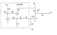
- FIG. 1shows a schematic circuit diagram illustrating a bias circuit using a current mirror configuration.
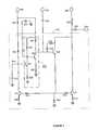
- FIG. 2shows another schematic circuit diagram illustrating a bias circuit using a current mirror configuration with feedback.
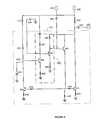
- FIG. 3shows a schematic circuit diagram of a bias circuit using a current mirror configuration with an amplifier circuit to provide stability against fluctuations, for instance due to temperature and/or supply voltage, and using a reference voltage supply and another voltage supply.
- FIG. 4shows a schematic circuit diagram of a bias circuit using a current mirror configuration with an amplifier circuit to provide stability against fluctuations, for instance due to temperature and/or supply voltage, with a single supply.
- the illustrative circuits described in FIGS. 1 - 4may be used to bias a one or more transistor.
- a regulated low voltage supply terminalprovides a reference current to a master transistor in a current mirror configuration.
- the mirrored current to a second transistor in the current mirror configurationserves as a suitable biasing current.
- the second transistor, biased by the current mirror arrangementmay concurrently be in a cascade arrangement of transistors.
- a power supply, including unregulated power supplies,may be connected to an output terminal with suitable isolation from the output signal, to provide the biasing current in accordance with a mirror current to the second transistor in the current mirror configuration.
- the cascade arrangement of transistorswhen present, may be used to provide high gain to an input signal.
- the described arrangementis preferably further stabilized by a feedback circuit comprising an amplifier to counteract variations at a current-sink terminal of the master transistor by adjusting the voltage at the control terminals of transistors in the current mirror.
- npn-type or pnp-type BJTsother varieties of HBTs, or field-effect transistors (“FETs”).
- FETsfield-effect transistors
- the inventionis particularly suited for use whenever the supply voltage is only slightly higher than twice the base-emitter voltage (for bipolar transistors) or the gate-source voltage (for FETs) of the transistors used in the bias circuit.
- a i, negative feedback loopprovides a stable voltage at the base of the transistors in the current mirror configuration.
- the effectiveness of this feedbackis directly sensitive to the gain in the loop, which is close to the gain of feedback amplifier times the gain of the reference transistor (also known as the master transistor).
- the gainis for providing biasing rather than amplifying high frequency signals, which may result in unstable operation. Therefore, the gain and phase relationships are tailored to ensure gain at low frequencies, preferably DC, while having a reduced or even absence of a gain at high frequencies that are to be amplified by the one or more transistors in the current mirror configuration.
- Such adjustments to the loop gainmay be made by the introduction of suitable reactances such as capacitors, inductors and the like.
- FIG. 1An example circuit of a current mirror arrangement is presented in FIG. 1.
- the input RF signalis received at input terminal 170 while the output is provided via capacitor 155 at output terminal 175 .
- Reference resistor 120in series with a voltage supply connected to terminal 105 provides a reference current I CM .
- Reference resistor 120cannot be so large as to result in the voltage at the collector of transistor 110 falling below 2.66V because transistors 130 and 115 require a voltage drop of at least twice the base-emitter voltage for being turned ON. Because transistors 130 and 115 are “stacked”, the circuit operates well only from a, power supply voltage that is substantially higher than twice the base-emitter voltage of the stacked transistors. Therefore for the illustrated circuit of FIG.
- Non-inverting amplifier 200serves, inter alia, two functions: (1) level-shifting the voltage at the collector of transistor 210 (and the base of transistor 285 ) to the required operating voltage of transistor 230 ; and (2) amplifying fluctuations in the voltage at the collector of transistor 210 .
- the voltage at the collector of transistor 110is about 2.66 V or more in order for transistors 115 and 130 to operate.
- the comparable voltage at the collector of transistor 210may be as low as about 1.5 V.
- inductors 260 and 265serve as RF chokes.
- Inductors 260 and 265are optional and inductor 260 may be replaced by a resistor in some embodiments.
- inductor 265isolates the bias circuit.
- a power supply voltageis applied through inductor 260 to transistor 215 .
- capacitors 250 and 255are de-coupling capacitors to isolate DC voltages from the input and output RF signals.
- Transistors in FIG. 1 or 2may additionally include, although not shown, resistors between their respective emitters and the ground or other voltage reference. Moreover, one or more of the transistors may be implemented as composite transistors.
- Resistor 220establishes a reference current I CM passing through transistor 210 and also a current I B into the base of transistor 285 . If reference voltage V REG increases, both the voltage at the base of transistor 285 and the current I B correspondingly increase. Thus, the collector-emitter current through transistor 285 increases, and the collector-emitter voltage of transistor 285 decreases, pulling down the voltage at the base of transistor 290 and amplifying the fluctuation in voltage at the base of transistor 285 . The decreased voltage at the base of transistor 290 causes the collector-emitter voltage of transistor 290 to increase, thus, pulling up the voltage at the base of transistor 230 .
- the collector-emitter voltage of transistor 230correspondingly decreases, thus pulling up the voltage at the emitter of transistor 230 .
- the current into the base of transistor 210in turn increases, causing the collector-emitter voltage of transistor 210 to decrease and thereby pulling down the voltage at its collector back to the desired quiescent value.
- the non-inverting amplifier 200provides sufficient gain in the feedback loop to compensate for variations in the supply voltage V REG .
- power supply voltages as low as 2.65 Vmay be used with, for instance GaAs HBT.
- this valuemay be lower or higher depending on the junction voltage, since it should preferably be slightly higher than twice the base-emitter voltage of the transistors in the circuit. For instance, it may be 2.25 for a junction voltage of about 1.1 V.
- the gain in the feedback loopis reduced at higher frequencies, which advantageously include the frequency ranges of interest for amplification of RF signals, to provide stable biasing without compromising stability.
- reactance due to one or more capacitors connected between the base of transistor 230 and ground, the base of transistor 285 and the emitter of transistor 290 , the collector of transistor 290 and emitter of transistor 285 , parasitic capacitance, and the likeadjusts the loop gain at high frequencies.
- a capacitance of about 1000 pF between the base of transistor 230 and the ground (or reference)may be employed.
- the disclosed inventionfurther encompasses the current mirror based biasing scheme applied to biasing gain blocks, and in particular to gain blocks using Darlington configurations. It is believed, without intending to be bound by any theory, that in a current-mirror configuration based bias circuit, a reference resistor may establish a reference current. If the temperature characteristics of the two transistors connected in the current mirror configuration are substantially the same, then the circuit is relatively insensitive to fluctuations in temperature.
- FIG. 3illustrates an embodiment of the invention for biasing a transistor in a Darlington configuration.
- regulated low voltage supply terminal 305provides a reference current, via resistances 320 and 322 , wherein optional resistance 320 is external to integrated circuit 301 .
- the reference currentflows to first transistor 310 , which is in a current mirror configuration, via resistors 335 and 340 with second transistor 315 .
- Resistor 345is an optional component that is useful in sinking excess current through transistor 330 .
- resistor 345may be used as a design parameter for the current mirror configuration.
- amplifier 300provides feedback responsive to variations at current-sink terminal 324 of first transistor 310 .
- second transistor 315 in the current mirror configurationis also in a Darlington arrangement, illustrated for instance, by its combination with transistor 330 .
- Radio frequency (RF) signalsare received at input 370 coupled to transistor 330 via blocking capacitor 350 .
- the output signalis provided at output terminal 375 via DC blocking capacitor 355 .
- Output terminal 375is also connected to power supply terminal 380 that provides a biasing current to the Darlington arrangement in accordance with the current mirror configuration.
- Capacitor 355 and RF choke 360allow substantial isolation of the output RF signal from the DC power supply connected to terminal 380 .
- capacitor 350blocks the DC current from the input RF signal at terminal 370 .
- An optional RF choke(not shown) between the emitter terminal of transistor 330 and the control terminal of transistor 310 provides further isolation of the RF amplifying transistors 330 and 315 from the transistor 310 .
- resistors 335 , 340 , 345 , 308 , 313 , 387 , 383 , 392 , and 388may be left out in alternative embodiments of the invention.
- resistors 308 and 313are matched along with transistors 310 and 315 in the current mirror configuration.
- Optional resistor 345provides a current sink to limit the current into the control terminals of the transistors in the current mirror configuration.
- Capacitors 394 and 312function, in one aspect, to stabilize the feed back loop by reducing the loop gain at high frequencies.
- Capacitor 394is connected between the control terminal of transistor 390 and the reference ground, while capacitor 312 is connected between the control terminal of transistor 310 and the reference ground.
- capacitor 334preferably provides a DC block, and with resistor 332 helps shape the loop gain to enhance stability of the bias circuit.
- the circuit depicted in FIG. 3is believed to enable drawing of a stable biasing current from power supply terminal 380 .
- This biasing currentunlike the typical gain block biasing circuits, does not require a large resistance in series with a large voltage source to approximate a stable current source. This is believed to be due to the current mirror relationship between the biasing current and the reference current passing through transistor 310 .
- the current mirror configurationis stabilized to compensate for temperature and regulated supply variations by the feedback provided by amplifier 300 .
- Amplifier 300comprises, inter alia, transistors 385 and 390 for amplifying the variations, typically due to temperature and supply voltage changes, at current-sink terminal 324 of first transistor 310 to provide feedback to counter such changes. This feedback adjusts the biasing current into the control terminals of transistors 310 and 315 via transistor 330 as shown in FIGS. 3 and 4 in a manner similar to the operation of the circuit of FIG. 2.
- FIG. 3illustrates transistor 330 in both the Darlington configuration and the feedback loop via a connection to amplifier 300 .
- the Darlington configurationmay include more than two transistors to regulate the biasing currents in alternative embodiments.
- Transistor 330is always ON with amplifier 300 output providing its control voltage for biasing it. Variations in voltage due to the input RF signal are typically too small to influence the biasing of transistor 330 .
- Resistor 332 and capacitor 334 across the collector and base of transistor 330provide optional current shaping and/or stability.
- transistor 315is both in the current mirror configuration and the Darlington configuration. The current mirror configuration provides stable biasing, in effect DC or relatively slowly varying voltage or currents, while the Darlington configuration provides a high gain to relatively high frequency signals.
- FIG. 4illustrates another embodiment with like elements being numbered with similar numerals as in FIGS. 1 - 3 to indicate similar components.
- the embodiment shown in FIG. 4differs from that in FIG. 3 in that it requires only one power supply for its gain block implemented in integrated circuit 3 .
- This embodimentalso provides protection against supply voltage and temperature variations by the feedback mechanism previously described in the context of FIG. 3.
- resistors 435 , 440 , 445 , 408 , 413 , 487 , 483 , 492 , and 488may be left out in alternative embodiments of the invention.
- resistors 408 and 413are matched along with transistors 410 and 415 in the current mirror configuration.
- Optional resistor 445provides a current sink to limit the current into the control terminals of the transistors in the current mirror configuration.
- Capacitors 494 and 412function, in one aspect, to stabilize the feed back loop by reducing the loop gain at high frequencies. Capacitor 494 is connected between the control terminal of transistor 490 and the reference ground, while capacitor 412 is connected between the control terminal of transistor 410 and the reference ground.
- Darlington arrangement illustrated in FIG. 3 or 4is not intended to be limit the scope of the invention, and instead is illustrative. Thus, additional Darlington arrangements may be connected. For instance, there may be another transistor similar to transistor 315 (or transistor 415 ) that may be concurrently in a current mirror and a Darlington configuration.
- a circuit for biasing a Darlington arrangementmultiple paths are provided for the reference current through a master transistor and a mirror current related to the reference current.
- the mirror currentis suitable for biasing transistors coupled in a Darlington arrangement such that one of the transistors is also a slave transistor in the current mirror arrangement.
- the mirror currentis related to the reference current by the relative transconductances of the master and slave transistors.
- the relative transconductances, a scaling factorare determined by the choice of resistors and the matching of the master and slave transistors in the current mirror configuration.
- bias circuitcapable of operating from a power supply that produces a voltage that is only slightly higher that twice the base-emitter voltage of the biased transistor.
- This bias circuitis suitable for biasing a gain block, for instance a Darlington configuration.
- one of the transistors in the Darlington configurationis a slave transistor in the current mirror configuration, while another transistor in the Darlington configuration is part of a feedback circuit to counter variations due to temperature and supply voltage.
- the disclosed bias circuitis made relatively insensitive to fluctuations in temperature by matching the master transistor in the current mirror configuration to the slave transistor. This condition may be satisfied, for instance, by manufacturing the master and slave transistors as matched transistors. Since one or more of the various transistors may be of the same transistor type as the transistor biased in the described manner, the bias circuit and the biased transistor may be implemented on the same integrated circuit.
- bias circuit of the present inventionadmit of many variations in addition to those noted previously.
- embodiments of the bias circuit of the present inventionare possible by, for instance eliminating one or more of inductors, capacitors, or the various optional resistors. Although many of these elements are optional, the stability and operation of the bias circuit is often improved by their presence in different embodiments.
- the stability of the bias circuitmay be increased by one or more phase-compensating R-C networks.
- bipolar and field-effect transistorsor a combination thereof may be used.
- One or more of the transistorsmay be implemented as composite transistors.
- the bipolar and field-effect transistors types of transistorshave terminals that are generally known by different names, the following terms will be used herein to describe generically the terminals of the transistors used in the invention: (1)
- the term “control terminal”includes, for instance, the gate of a FET and the base of a bipolar transistor; (2) the term “current-source terminal” includes, for instance, the drain of a FET and the collector of a bipolar transistor; and (3) the term “current-sink terminal” includes, for instance, the source of a FET and the emitter of a bipolar transistor.
Landscapes
- Engineering & Computer Science (AREA)
- Power Engineering (AREA)
- Microelectronics & Electronic Packaging (AREA)
- Physics & Mathematics (AREA)
- Nonlinear Science (AREA)
- Electromagnetism (AREA)
- General Physics & Mathematics (AREA)
- Radar, Positioning & Navigation (AREA)
- Automation & Control Theory (AREA)
- Amplifiers (AREA)
Abstract
Description
- This application is a continuation-in-part of U.S. patent application Ser. No. 09/875,117 filed Jun. 6, 2001, by Henry Z. Liwinski entitled “Bias Circuit For Use With Low-Voltage Power Supply,” which is incorporated by reference herein in its entirety, and claims the benefit thereof under 35 U.S.C. §120.[0001]
- The present invention relates generally to a circuit for biasing a gain block using a large unregulated power supply with the aid of a low-power stable power supply for increased efficiency in the operation of the gain block.[0002]
- Modem wireless communications devices, such as cellular telephones, are held to ever-higher performance standards. Transmissions must be clear and undistorted, and the battery in the devices must be small and have a long life. In order to meet these consumer requirements, wireless telephone designers have moved away from using traditional silicon-based bipolar transistors as power amplifiers and toward using more exotic transistors, such as heterojunction bipolar transistors (“HBTs”) made of aluminum-gallium-arsenide/gallium-arsenide (“AlGaAs/GaAs”), indium-gallium-phosphide/gallium-arsenide (“InGaP/GaAs”), InGaP/GaAsN, and double heterojunction bipolar transistor (DHBT) in an non-exhaustive listing. Such HBTs provide improved power efficiency and linearity, thus enabling cellular phones to achieve longer battery life and better signal characteristics for voice and data.[0003]
- Of course, an HBT, like a bipolar junction transistor (“BJT”), requires a direct-current (“DC”) bias signal (comprising both a voltage and a current) to be applied to the input terminal to establish its operating point. (The operating point of a transistor may be defined as the point on the transistor's characteristic curves at which the transistor will operate in the absence of an input signal. See, e.g., John Markus, Electronics Dictionary 445 (4th ed. 1979).) Because changes in the DC bias signal affect the operating point of the HBT (and thus adversely affect the linearity of the amplifier), the DC bias signal must be stable and unaffected by variations in temperature or in the power supply voltage. Typically a “bias circuit” generates such a DC bias signal.[0004]
- In addition, it is desirable to use amplifying circuits based on the HBT, like the BJT, as off-the-shelf gain blocks for implementing particular device designs. An early and still popular design for such gain blocks is based on the Darlington transistor, which is also known as the Darlington pair. The Darlington arrangement is named after Sydney Darlington of Bell Labs who first proposed the arrangement and received the U.S. Pat. No. 2,663,806 describing it on Dec. 22, 1953. The Darlington arrangement provides high current gain by connecting two (or more) transistors in a cascade configuration with the collectors of the transistors connected together and the emitter of one transistor connected to the base of the other transistor. Resistors connected across the base-emitter of each transistor allow independent design of bias current and reduce the time to turn OFF the conducting pair. In principle more than two transistors may be employed in a Darlington arrangement although typically two transistors are used.[0005]
- An example of a Darlington pair based gain block is the HBT technology based MINI-CIRCUITS® ERA series of amplifiers for wide-band microwave (from about 50 to 8000 MHz) amplification. These amplifiers are four terminal devices with two of the terminals (pins 2 and 4) connected to ground. Biasing is through the output terminal, which is connected to the supply voltage through a biasing resistor and a recommended RF wide-band choke. This arrangement reflects the current biased nature of the device making it more sensitive to current than voltage fluctuations. Hence a voltage source is approximated as a current source with the use of the biasing resistor for adequate biasing. In addition, the supply is isolated from stray signals by a suitable bypass capacitor. The input (at terminal labeled as pin 1) and output (at terminal labeled as pin 3) signals are provided via respective DC blocking capacitors.[0006]
- Proper biasing of the aforementioned ERA and similar devices requires an adequately regulated supply voltage. In order to maintain constant operating conditions the recommended supply voltage for such devices is, typically, significantly greater than the device voltage. The device voltage, i.e., the voltage across the device, is modeled to be dependent on both the bias current and the temperature such that it increases with increase in bias current and decreases with increase in device temperature. The use of a large biasing resistor proportionally reduces the variation in the bias current due to temperature or voltage changes since most of the change is in the voltage across the biasing resistor. Alternative temperature compensated biasing of ERA like devices includes a combination of a linear positive-temperature-coefficient thermistor in parallel with a regular resistor such that the decrease in device voltage with temperature is offset by an increase in the resistance of this combination, which is placed in series with the biasing resistor.[0007]
- The approximate current source configurations described above necessarily result in significant resistive losses resulting in low efficiency. For instance, in the described resistive biasing scheme increasing the supply voltage relative to the specified device voltage improves stability by reducing voltage fluctuations at the device due to fluctuations in the supply voltage. However, this increase in stability is coupled with a reduction in the overall efficiency due to increased resistive losses. This tradeoff results in a preferred value for the supply voltage at about twice the device voltage value. In the case of typical Darlington amplifiers, the expected efficiency is about 15% to 25%.[0008]
- The invention encompasses bias circuit designs that improve performance and efficiency resulting in longer battery life in portable devices due to reduced power requirement and the ability to use power supplies with lower voltages. In particular, the invention encompasses bias circuits implemented with InGaP/GaAs or AlGaAs/GaAs HBTs that are capable of operating from a regulated supply voltage that is as low as about 2.7 V, which is about twice the junction voltage, for instance the base-emitter junction voltage. Preferably, these circuits may be manufactured on a single integrated circuit. The disclosed circuits employ a current mirror configuration to bias gain blocks. Optionally, the gain blocks include transistors arranged in a cascade, such as a Darlington configuration, for high amplification. The invention also encompasses transistors of various other types that may be employed to realize cascaded transistors in gain blocks.[0009]
- The use of the current mirror configuration enables the use of a low voltage regulated supply or a preferred regulated supply to provide a reference current to a master transistor in the current mirror configuration. The mirrored current, being stabilized by its being proportional to the reference current, then is used to bias one or more transistors powered by a relatively unregulated power supply. Thus, the familiar constraint requiring the power supply voltage to be significantly greater than device voltage in order to provide stable biasing is relaxed resulting in lower resistive losses and improved efficiency.[0010]
- In another aspect, the invention encompasses providing stability with respect to temperature and process variations by way of feedback provided in current mirror configurations disclosed herein. The invention also encompasses configurations wherein one or more transistors in a cascade configuration are also a part of the current mirror configuration or a feedback loop therein.[0011]
- In a preferred embodiment, the bias circuit includes a first transistor connected in a current-mirror configuration with the transistor to be biased (“the biased transistor”) and a feedback circuit. The voltage at the collector of the first transistor is fed back via the feedback circuit to control the voltage at the bases of the first transistor and the biased transistor, which are connected in the current mirror configuration.[0012]
- The feedback circuit comprises, in a preferred embodiment, a non-inverting amplifier, containing one or more transistors, such that the input of the non-inverting amplifier is connected to the collector of the first transistor and at its output is connected to a second transistor in an emitter-follower configuration. Preferably, the non-inverting amplifier comprises two or more transistors in a cascade connected to the second transistor. The second transistor is connected at its collector to the power supply and at its emitter to the node formed by the bases of the first transistor and the biased transistor. It thus establishes base currents entering the first transistor and the biased transistor. The collector-emitter current passing through the first transistor (which is mirrored in the biased transistor by a proportional current) is thereby maintained substantially constant via negative feedback. The bias circuit additionally comprises several current-limiting resistive elements and one or more inductors that serve as RF chokes.[0013]
- Also described herein is a method of biasing a first transistor having a base, emitter, and collector via a circuit that includes a second transistor, which, in turn, is connected in a current-mirror configuration with the first transistor. The method includes the steps of monitoring an electrical characteristic (for example, a current or a voltage) at the collector of the second transistor, amplifying the monitored characteristic, and feeding back the amplified characteristic to control the second transistor. The step of amplifying may further include the steps of inverting the monitored characteristic and, optionally, re-inverting the characteristic. In addition, the method optionally comprises level-shifting the monitored characteristic.[0014]
- In an aspect of the invention, the feedback circuit preferably provides a positive gain at low frequencies, including DC, to bias one or more transistors, and a lower gain and optional phase adjustment at higher frequencies, such as the RF frequencies amplified by the gain block, to provide stable performance. The adjustment of the gain at high frequencies may be provided by a suitable reactance in the feed back circuit, for instance a capacitor to shunt the high frequencies, and the like.[0015]
- FIG. 1 shows a schematic circuit diagram illustrating a bias circuit using a current mirror configuration.[0016]
- FIG. 2 shows another schematic circuit diagram illustrating a bias circuit using a current mirror configuration with feedback.[0017]
- FIG. 3 shows a schematic circuit diagram of a bias circuit using a current mirror configuration with an amplifier circuit to provide stability against fluctuations, for instance due to temperature and/or supply voltage, and using a reference voltage supply and another voltage supply.[0018]
- FIG. 4 shows a schematic circuit diagram of a bias circuit using a current mirror configuration with an amplifier circuit to provide stability against fluctuations, for instance due to temperature and/or supply voltage, with a single supply.[0019]
- In general, the illustrative circuits described in FIGS.[0020]1-4 may be used to bias a one or more transistor. A regulated low voltage supply terminal provides a reference current to a master transistor in a current mirror configuration. The mirrored current to a second transistor in the current mirror configuration serves as a suitable biasing current. The second transistor, biased by the current mirror arrangement, may concurrently be in a cascade arrangement of transistors. A power supply, including unregulated power supplies, may be connected to an output terminal with suitable isolation from the output signal, to provide the biasing current in accordance with a mirror current to the second transistor in the current mirror configuration. The cascade arrangement of transistors, when present, may be used to provide high gain to an input signal. The described arrangement is preferably further stabilized by a feedback circuit comprising an amplifier to counteract variations at a current-sink terminal of the master transistor by adjusting the voltage at the control terminals of transistors in the current mirror.
- Although, various embodiments of the invention are described as a bias circuit composed of HBTs, the invention is not limited to such transistors. An alternative embodiment of the invention may be readily constructed with, e.g., npn-type or pnp-type BJTs, other varieties of HBTs, or field-effect transistors (“FETs”). The invention is particularly suited for use whenever the supply voltage is only slightly higher than twice the base-emitter voltage (for bipolar transistors) or the gate-source voltage (for FETs) of the transistors used in the bias circuit.[0021]
- In the illustrative current mirror biasing arrangements described herein, a i, negative feedback loop provides a stable voltage at the base of the transistors in the current mirror configuration. The effectiveness of this feedback is directly sensitive to the gain in the loop, which is close to the gain of feedback amplifier times the gain of the reference transistor (also known as the master transistor). The gain is for providing biasing rather than amplifying high frequency signals, which may result in unstable operation. Therefore, the gain and phase relationships are tailored to ensure gain at low frequencies, preferably DC, while having a reduced or even absence of a gain at high frequencies that are to be amplified by the one or more transistors in the current mirror configuration. Such adjustments to the loop gain may be made by the introduction of suitable reactances such as capacitors, inductors and the like.[0022]
- An example circuit of a current mirror arrangement is presented in FIG. 1. The input RF signal is received at[0023]
input terminal 170 while the output is provided viacapacitor 155 atoutput terminal 175.Reference resistor 120 in series with a voltage supply connected toterminal 105 provides a reference current ICM. Reference resistor120 cannot be so large as to result in the voltage at the collector oftransistor 110 falling below 2.66V becausetransistors transistors optional resistors capacitors optional inductor 165 provides RF isolation toRF amplifying transistor 115 from themaster transistor 110. - Another example bias circuit that can operate from lower supply voltages is illustrated in FIG. 2 with[0024]
non-inverting amplifier 200 comprisingadditional transistors optional resistors Non-inverting amplifier 200 serves, inter alia, two functions: (1) level-shifting the voltage at the collector of transistor210 (and the base of transistor285) to the required operating voltage oftransistor 230; and (2) amplifying fluctuations in the voltage at the collector oftransistor 210. In the circuit of FIG. 1 (shown without a non-inverting amplifier), the voltage at the collector oftransistor 110 is about 2.66 V or more in order fortransistors transistor 210 may be as low as about 1.5 V. - As in the circuit of FIG. 1, in FIG. 2 preferably[0025]
inductors 260 and265 serve as RF chokes.Inductors 260 and265 are optional and inductor260 may be replaced by a resistor in some embodiments. When present,inductor 265 isolates the bias circuit. A power supply voltage is applied through inductor260 totransistor 215. Preferablycapacitors - The operation of the circuit in FIG. 2 is, believed to be, without being bound by theory, as follows.[0026]
Resistor 220 establishes a reference current ICMpassing throughtransistor 210 and also a current IBinto the base oftransistor 285. If reference voltage VREGincreases, both the voltage at the base oftransistor 285 and the current IBcorrespondingly increase. Thus, the collector-emitter current throughtransistor 285 increases, and the collector-emitter voltage oftransistor 285 decreases, pulling down the voltage at the base oftransistor 290 and amplifying the fluctuation in voltage at the base oftransistor 285. The decreased voltage at the base oftransistor 290 causes the collector-emitter voltage oftransistor 290 to increase, thus, pulling up the voltage at the base oftransistor 230. The collector-emitter voltage oftransistor 230 correspondingly decreases, thus pulling up the voltage at the emitter oftransistor 230. The current into the base oftransistor 210 in turn increases, causing the collector-emitter voltage oftransistor 210 to decrease and thereby pulling down the voltage at its collector back to the desired quiescent value. - Preferably, the[0027]
non-inverting amplifier 200 provides sufficient gain in the feedback loop to compensate for variations in the supply voltage VREG. Thus, power supply voltages as low as 2.65 V may be used with, for instance GaAs HBT. For different transistors this value may be lower or higher depending on the junction voltage, since it should preferably be slightly higher than twice the base-emitter voltage of the transistors in the circuit. For instance, it may be 2.25 for a junction voltage of about 1.1 V. - As discussed previously, the gain in the feedback loop is reduced at higher frequencies, which advantageously include the frequency ranges of interest for amplification of RF signals, to provide stable biasing without compromising stability. To this end, although not shown in FIG. 2, reactance due to one or more capacitors connected between the base of[0028]
transistor 230 and ground, the base oftransistor 285 and the emitter oftransistor 290, the collector oftransistor 290 and emitter oftransistor 285, parasitic capacitance, and the like adjusts the loop gain at high frequencies. In an example circuit, a capacitance of about 1000 pF between the base oftransistor 230 and the ground (or reference) may be employed. - The disclosed invention further encompasses the current mirror based biasing scheme applied to biasing gain blocks, and in particular to gain blocks using Darlington configurations. It is believed, without intending to be bound by any theory, that in a current-mirror configuration based bias circuit, a reference resistor may establish a reference current. If the temperature characteristics of the two transistors connected in the current mirror configuration are substantially the same, then the circuit is relatively insensitive to fluctuations in temperature.[0029]
- FIG. 3 illustrates an embodiment of the invention for biasing a transistor in a Darlington configuration. In this circuit regulated low[0030]
voltage supply terminal 305 provides a reference current, viaresistances optional resistance 320 is external tointegrated circuit 301. The reference current flows tofirst transistor 310, which is in a current mirror configuration, viaresistors second transistor 315.Resistor 345 is an optional component that is useful in sinking excess current throughtransistor 330. Along withresistors resistor 345 may be used as a design parameter for the current mirror configuration. In addition,amplifier 300 provides feedback responsive to variations at current-sink terminal 324 offirst transistor 310. It should be noted thatsecond transistor 315 in the current mirror configuration is also in a Darlington arrangement, illustrated for instance, by its combination withtransistor 330. - Radio frequency (RF) signals are received at[0031]
input 370 coupled totransistor 330 via blockingcapacitor 350. The output signal is provided atoutput terminal 375 viaDC blocking capacitor 355.Output terminal 375 is also connected topower supply terminal 380 that provides a biasing current to the Darlington arrangement in accordance with the current mirror configuration.Capacitor 355 and RF choke360 allow substantial isolation of the output RF signal from the DC power supply connected toterminal 380. Similarly capacitor350 blocks the DC current from the input RF signal atterminal 370. An optional RF choke (not shown) between the emitter terminal oftransistor 330 and the control terminal oftransistor 310 provides further isolation of theRF amplifying transistors transistor 310. - One or more of[0032]
optional resistors resistors transistors Optional resistor 345 provides a current sink to limit the current into the control terminals of the transistors in the current mirror configuration.Capacitors Capacitor 394 is connected between the control terminal oftransistor 390 and the reference ground, whilecapacitor 312 is connected between the control terminal oftransistor 310 and the reference ground. Similarly,capacitor 334 preferably provides a DC block, and withresistor 332 helps shape the loop gain to enhance stability of the bias circuit. - Without intending to be bound by any theory, the circuit depicted in FIG. 3 is believed to enable drawing of a stable biasing current from[0033]
power supply terminal 380. This biasing current, unlike the typical gain block biasing circuits, does not require a large resistance in series with a large voltage source to approximate a stable current source. This is believed to be due to the current mirror relationship between the biasing current and the reference current passing throughtransistor 310. Moreover, the current mirror configuration is stabilized to compensate for temperature and regulated supply variations by the feedback provided byamplifier 300.Amplifier 300 comprises, inter alia,transistors sink terminal 324 offirst transistor 310 to provide feedback to counter such changes. This feedback adjusts the biasing current into the control terminals oftransistors transistor 330 as shown in FIGS. 3 and 4 in a manner similar to the operation of the circuit of FIG. 2. - FIG. 3 illustrates[0034]
transistor 330 in both the Darlington configuration and the feedback loop via a connection toamplifier 300. The Darlington configuration, of course, may include more than two transistors to regulate the biasing currents in alternative embodiments.Transistor 330 is always ON withamplifier 300 output providing its control voltage for biasing it. Variations in voltage due to the input RF signal are typically too small to influence the biasing oftransistor 330.Resistor 332 andcapacitor 334 across the collector and base oftransistor 330 provide optional current shaping and/or stability. In addition,transistor 315 is both in the current mirror configuration and the Darlington configuration. The current mirror configuration provides stable biasing, in effect DC or relatively slowly varying voltage or currents, while the Darlington configuration provides a high gain to relatively high frequency signals. - FIG. 4 illustrates another embodiment with like elements being numbered with similar numerals as in FIGS.[0035]1-3 to indicate similar components. In one respect, the embodiment shown in FIG. 4 differs from that in FIG. 3 in that it requires only one power supply for its gain block implemented in integrated circuit3. This embodiment also provides protection against supply voltage and temperature variations by the feedback mechanism previously described in the context of FIG. 3.
- As in FIG. 3, one or more of[0036]
optional resistors resistors transistors Optional resistor 445 provides a current sink to limit the current into the control terminals of the transistors in the current mirror configuration.Capacitors Capacitor 494 is connected between the control terminal of transistor490 and the reference ground, whilecapacitor 412 is connected between the control terminal oftransistor 410 and the reference ground. - It is believed that the lower losses and improved efficiency result from the circuits shown in FIGS. 3 and 4 because a large power supply voltage compared to the device voltage is not required for implementing a stable current source to bias the Darlington configuration. For instance, providing a reference current to a master transistor from a regulated low voltage supply requires a smaller resistive loss than employing a high voltage supply. A mirror current related to the reference current may be drawn from another supply, not necessarily as well regulated as the supply connected to terminal[0037]305 or405, to provide a biasing current that is almost as well regulated as the reference current. This mirror current is suitable as a biasing current for a Darlington arrangement with lower resistive losses compared to the typical gain block biasing schemes.
- It should be noted that the Darlington arrangement illustrated in FIG. 3 or[0038]4 is not intended to be limit the scope of the invention, and instead is illustrative. Thus, additional Darlington arrangements may be connected. For instance, there may be another transistor similar to transistor315 (or transistor415) that may be concurrently in a current mirror and a Darlington configuration.
- In designing a circuit for biasing a Darlington arrangement, multiple paths are provided for the reference current through a master transistor and a mirror current related to the reference current. The mirror current is suitable for biasing transistors coupled in a Darlington arrangement such that one of the transistors is also a slave transistor in the current mirror arrangement. The mirror current is related to the reference current by the relative transconductances of the master and slave transistors. The relative transconductances, a scaling factor, are determined by the choice of resistors and the matching of the master and slave transistors in the current mirror configuration.[0039]
- In summary, methods and systems have been disclosed for providing a bias circuit capable of operating from a power supply that produces a voltage that is only slightly higher that twice the base-emitter voltage of the biased transistor. This bias circuit is suitable for biasing a gain block, for instance a Darlington configuration. Preferably, one of the transistors in the Darlington configuration is a slave transistor in the current mirror configuration, while another transistor in the Darlington configuration is part of a feedback circuit to counter variations due to temperature and supply voltage. The disclosed bias circuit is made relatively insensitive to fluctuations in temperature by matching the master transistor in the current mirror configuration to the slave transistor. This condition may be satisfied, for instance, by manufacturing the master and slave transistors as matched transistors. Since one or more of the various transistors may be of the same transistor type as the transistor biased in the described manner, the bias circuit and the biased transistor may be implemented on the same integrated circuit.[0040]
- One skilled in the art will recognize that the disclosed system and methods admit of many variations in addition to those noted previously. Alternative, embodiments of the bias circuit of the present invention are possible by, for instance eliminating one or more of inductors, capacitors, or the various optional resistors. Although many of these elements are optional, the stability and operation of the bias circuit is often improved by their presence in different embodiments. In addition, for particular bias circuits and the power amplifiers (for example based on the type of transistor used, the gain in the bias circuit feedback loop, or the parameters of the non-inverting amplifier), the stability of the bias circuit may be increased by one or more phase-compensating R-C networks.[0041]
- Since the invention can be practiced with various types of transistor like devices. For instance, either bipolar and field-effect transistors, or a combination thereof may be used. One or more of the transistors may be implemented as composite transistors. Since the bipolar and field-effect transistors types of transistors have terminals that are generally known by different names, the following terms will be used herein to describe generically the terminals of the transistors used in the invention: (1) The term “control terminal” includes, for instance, the gate of a FET and the base of a bipolar transistor; (2) the term “current-source terminal” includes, for instance, the drain of a FET and the collector of a bipolar transistor; and (3) the term “current-sink terminal” includes, for instance, the source of a FET and the emitter of a bipolar transistor.[0042]
- All references cited herein or otherwise relied upon are incorporated herein by reference in their entirety. It is further understood that the embodiments described herein are merely illustrative and are not intended to limit the scope of the invention. One skilled in the art may make various changes, rearrangements and modifications to the illustrative embodiments described above without substantially departing from the principles of the invention, which is limited only in accordance with the claims. Accordingly, all such deviations and departures should be interpreted to be within the spirit and scope of the following claims.[0043]
Claims (21)
Priority Applications (1)
| Application Number | Priority Date | Filing Date | Title |
|---|---|---|---|
| US10/319,921US6842075B2 (en) | 2001-06-06 | 2002-12-13 | Gain block with stable internal bias from low-voltage power supply |
Applications Claiming Priority (2)
| Application Number | Priority Date | Filing Date | Title |
|---|---|---|---|
| US09/875,117US6515546B2 (en) | 2001-06-06 | 2001-06-06 | Bias circuit for use with low-voltage power supply |
| US10/319,921US6842075B2 (en) | 2001-06-06 | 2002-12-13 | Gain block with stable internal bias from low-voltage power supply |
Related Parent Applications (1)
| Application Number | Title | Priority Date | Filing Date |
|---|---|---|---|
| US09/875,117Continuation-In-PartUS6515546B2 (en) | 2001-06-06 | 2001-06-06 | Bias circuit for use with low-voltage power supply |
Publications (2)
| Publication Number | Publication Date |
|---|---|
| US20030155977A1true US20030155977A1 (en) | 2003-08-21 |
| US6842075B2 US6842075B2 (en) | 2005-01-11 |
Family
ID=46281710
Family Applications (1)
| Application Number | Title | Priority Date | Filing Date |
|---|---|---|---|
| US10/319,921Expired - LifetimeUS6842075B2 (en) | 2001-06-06 | 2002-12-13 | Gain block with stable internal bias from low-voltage power supply |
Country Status (1)
| Country | Link |
|---|---|
| US (1) | US6842075B2 (en) |
Cited By (11)
| Publication number | Priority date | Publication date | Assignee | Title |
|---|---|---|---|---|
| US7313176B1 (en)* | 2003-09-11 | 2007-12-25 | Xilinx, Inc. | Programmable on chip regulators with bypass |
| US20080285624A1 (en)* | 2006-08-29 | 2008-11-20 | Atsushi Igarashi | Temperature Sensor Circuit |
| US20100039168A1 (en)* | 2008-08-12 | 2010-02-18 | Bettencourt John P | Bias network |
| US20110291764A1 (en)* | 2010-05-28 | 2011-12-01 | Rf Micro Devices, Inc. | Linear fet feedback amplifier |
| KR101161476B1 (en)* | 2006-09-08 | 2012-07-02 | 스카이워크스 솔루션즈, 인코포레이티드 | Amplifier feedback and bias configuration |
| US20130137383A1 (en)* | 2010-05-28 | 2013-05-30 | Rf Micro Devices, Inc. | Linear fet feedback amplifier |
| WO2017047398A1 (en)* | 2015-09-15 | 2017-03-23 | ソニーセミコンダクタソリューションズ株式会社 | Current mirror circuit and image sensor |
| US9722552B2 (en) | 2014-07-10 | 2017-08-01 | Qorvo Us, Inc. | Linear FET feedback amplifier |
| US10911000B2 (en)* | 2018-10-26 | 2021-02-02 | Murata Manufacturing Co., Ltd. | Power amplifier module |
| US11509273B2 (en) | 2019-08-27 | 2022-11-22 | Skyworks Solutions, Inc. | Apparatus and methods for power amplifier distortion network |
| JP2025504243A (en)* | 2022-06-01 | 2025-02-06 | 深▲せん▼▲飛▼▲驤▼科技股▲ふん▼有限公司 | Temperature compensated bias circuit and power amplifier |
Families Citing this family (25)
| Publication number | Priority date | Publication date | Assignee | Title |
|---|---|---|---|---|
| WO2003081771A1 (en)* | 2002-03-20 | 2003-10-02 | Roke Manor Research Limited | A bias circuit for a bipolar transistor |
| US6943629B2 (en)* | 2002-08-26 | 2005-09-13 | Mikhail Mordkovich | Transient protection circuit of Darlington amplifier |
| US6922107B1 (en)* | 2002-12-23 | 2005-07-26 | Dynalinear Technologies, Inc. | Dual (constant voltage/constant current) bias supply for linear power amplifiers |
| US7026876B1 (en) | 2003-02-21 | 2006-04-11 | Dynalinear Technologies, Inc. | High linearity smart HBT power amplifiers for CDMA/WCDMA application |
| US7057461B1 (en) | 2003-03-19 | 2006-06-06 | Dynalinear Technologies, Inc. | Heterostructure bipolar transistor power amplifier module with dynamic voltage supply for improved efficiency |
| KR100550930B1 (en)* | 2003-05-15 | 2006-02-13 | 학교법인 한국정보통신학원 | Active Bias Circuit for Power Amplifiers |
| US7009452B2 (en)* | 2003-10-16 | 2006-03-07 | Solarflare Communications, Inc. | Method and apparatus for increasing the linearity and bandwidth of an amplifier |
| US7746590B2 (en)* | 2004-10-06 | 2010-06-29 | Agere Systems Inc. | Current mirrors having fast turn-on time |
| US7358816B2 (en)* | 2004-11-11 | 2008-04-15 | Samsung Electronics Co., Ltd. | Variable gain amplifier |
| TW200637139A (en)* | 2005-04-06 | 2006-10-16 | Richwave Technology Corp | Adaptive linear biasing circuit |
| US20070040613A1 (en)* | 2005-08-19 | 2007-02-22 | Chow Yut H | Isolated stable bias circuit |
| JPWO2007043122A1 (en)* | 2005-09-30 | 2009-04-16 | 富士通株式会社 | Variable gain amplifier and control method thereof |
| US7639080B2 (en)* | 2006-06-07 | 2009-12-29 | Panasonic Corporation | Radio frequency amplifier circuit and mobile communication terminal using the same |
| US7609113B2 (en)* | 2006-11-15 | 2009-10-27 | Triquint Semiconductor, Inc. | Constant current bias circuit and associated method |
| JP4271708B2 (en)* | 2007-02-01 | 2009-06-03 | シャープ株式会社 | Power amplifier and multistage amplifier circuit including the same |
| JP4946728B2 (en)* | 2007-08-23 | 2012-06-06 | 三菱電機株式会社 | Power amplifier |
| US7714659B2 (en)* | 2008-07-25 | 2010-05-11 | Infineon Technologies Ag | Bias circuit with a feedback path and a method for providing a biasing signal |
| WO2010019249A2 (en) | 2008-08-12 | 2010-02-18 | Solarflare Communications, Inc. | Method and apparatus for reducing transmitter ac-coupling droop |
| JP5120157B2 (en)* | 2008-09-02 | 2013-01-16 | 富士通株式会社 | Amplifier circuit and driver circuit for optical modulator |
| US7907012B2 (en)* | 2008-10-21 | 2011-03-15 | Analog Devices, Inc. | Current mirror with low headroom and linear response |
| JP5939404B2 (en)* | 2013-03-19 | 2016-06-22 | 株式会社村田製作所 | Radio frequency amplifier circuit and power amplifier module |
| EP2922199B1 (en)* | 2014-03-17 | 2020-05-13 | Nxp B.V. | A bias circuit for a transistor amplifier |
| US12065381B2 (en) | 2019-07-11 | 2024-08-20 | Skyworks Solutions, Inc. | Temperature-stable, low-dielectric constant material with an ultra-low loss tangent |
| US12015382B1 (en)* | 2020-11-05 | 2024-06-18 | Scientific Components Corporation | Method and apparatus for a linearized RF amplifier current source |
| KR20220094935A (en)* | 2020-12-29 | 2022-07-06 | 삼성전기주식회사 | Protection circuit of power amplifier and power amplifier including the same |
Citations (81)
| Publication number | Priority date | Publication date | Assignee | Title |
|---|---|---|---|---|
| US2663806A (en)* | 1952-05-09 | 1953-12-22 | Bell Telephone Labor Inc | Semiconductor signal translating device |
| US3168706A (en)* | 1959-10-02 | 1965-02-02 | Hasler A G Werke Fur Telephoni | Multi-stage transistor amplifier with operating point stabilization |
| US3392342A (en)* | 1965-12-13 | 1968-07-09 | Ibm | Transistor amplifier with gain stability |
| US3491203A (en)* | 1966-10-18 | 1970-01-20 | Sonotone Corp | Temperature stabilized amplifier |
| US3534279A (en)* | 1968-08-12 | 1970-10-13 | Rca Corp | High current transistor amplifier stage operable with low current biasing |
| US3566289A (en)* | 1969-03-17 | 1971-02-23 | Bendix Corp | Current amplifier and inverting circuits |
| US3801831A (en)* | 1972-10-13 | 1974-04-02 | Motorola Inc | Voltage level shifting circuit |
| US3855541A (en)* | 1973-10-05 | 1974-12-17 | A Leidich | Current proportioning circuit |
| US3899743A (en)* | 1974-01-07 | 1975-08-12 | Gen Electric | Biasing circuit for multistage transistor amplifiers |
| USRE28633E (en)* | 1970-12-30 | 1975-11-25 | Solid state digital-to-analog converter | |
| US3936725A (en)* | 1974-08-15 | 1976-02-03 | Bell Telephone Laboratories, Incorporated | Current mirrors |
| US3940760A (en)* | 1975-03-21 | 1976-02-24 | Analog Devices, Inc. | Digital-to-analog converter with current source transistors operated accurately at different current densities |
| US3946327A (en)* | 1974-10-23 | 1976-03-23 | Rca Corporation | Amplifier employing complementary field-effect transistors |
| US3978473A (en)* | 1973-05-01 | 1976-08-31 | Analog Devices, Inc. | Integrated-circuit digital-to-analog converter |
| US3984830A (en)* | 1974-10-18 | 1976-10-05 | Westinghouse Electric Corporation | Complementary FET digital to analog converter |
| US4024415A (en)* | 1974-12-20 | 1977-05-17 | Matsura Yoshiaki | Detecting device for detecting battery outlet voltage |
| US4064506A (en)* | 1976-04-08 | 1977-12-20 | Rca Corporation | Current mirror amplifiers with programmable current gains |
| US4103246A (en)* | 1977-09-06 | 1978-07-25 | Rca Corporation | Switchable current amplifier |
| US4117417A (en)* | 1977-09-06 | 1978-09-26 | Rca Corporation | Switchable current amplifiers |
| US4117416A (en)* | 1977-11-28 | 1978-09-26 | Rca Corporation | Current mirror amplifiers with programmable current gains |
| US4119924A (en)* | 1977-09-06 | 1978-10-10 | Rca Corporation | Switchable current amplifiers |
| USRE29910E (en)* | 1975-08-04 | 1979-02-13 | Rca Corporation | Current mirror amplifier |
| US4140977A (en)* | 1978-01-16 | 1979-02-20 | Rca Corporation | Signal translation circuits |
| US4241315A (en)* | 1979-02-23 | 1980-12-23 | Harris Corporation | Adjustable current source |
| US4329247A (en)* | 1980-11-06 | 1982-05-11 | Pdi, Inc. | Stain remover for vinyl materials |
| US4361816A (en)* | 1980-06-30 | 1982-11-30 | Rca Corporation | Current mirror amplifiers with programmable gain |
| US4450366A (en)* | 1980-09-26 | 1984-05-22 | Malhi Satwinder D | Improved current mirror biasing arrangement for integrated circuits |
| US4462005A (en)* | 1981-06-15 | 1984-07-24 | Tokyo Shibaura Denki Kabushiki Kaisha | Current mirror circuit |
| US4475077A (en)* | 1981-12-11 | 1984-10-02 | Tokyo Shibaura Denki Kabushiki Kaisha | Current control circuit |
| US4525682A (en)* | 1984-02-07 | 1985-06-25 | Zenith Electronics Corporation | Biased current mirror having minimum switching delay |
| US4654602A (en)* | 1984-12-25 | 1987-03-31 | Kabushiki Kaisha Toshiba | Current mirror circuit |
| US4857864A (en)* | 1987-06-05 | 1989-08-15 | Kabushiki Kaisha Toshiba | Current mirror circuit |
| US4897614A (en)* | 1987-07-17 | 1990-01-30 | Kabushiki Kaisha Toshiba | Current mirror circuit |
| US4990864A (en)* | 1990-02-07 | 1991-02-05 | Texas Instruments Incorporated | Current amplifier circuit |
| US5079518A (en)* | 1989-11-17 | 1992-01-07 | Kabushiki Kaisha Toshiba | Current-mirror circuit with buffering transistor |
| US5283537A (en)* | 1991-07-31 | 1994-02-01 | Canon Kabushiki Kaisha | Current mirror circuit |
| US5307023A (en)* | 1992-10-16 | 1994-04-26 | Harris Corporation | Non-linear operational transconductance amplifier |
| US5398004A (en)* | 1994-02-09 | 1995-03-14 | Trw Inc. | HBT direct-coupled low noise wideband microwave amplifier |
| US5404585A (en)* | 1991-09-19 | 1995-04-04 | Nokia Mobile Phones Ltd. | Power detector that employs a feedback circuit to enable class B operation of a detector transistor |
| US5412336A (en)* | 1993-11-10 | 1995-05-02 | Motorola, Inc. | Self-biasing boot-strapped cascode amplifier |
| US5444361A (en)* | 1992-09-23 | 1995-08-22 | Sgs-Thomson Microelectronics, Inc. | Wideband linear and logarithmic signal conversion circuits |
| US5451908A (en)* | 1993-09-02 | 1995-09-19 | Temic Telefunken Microelectronic Gmbh | Circuit arrangement with controlled pinch resistors |
| US5548248A (en)* | 1995-07-30 | 1996-08-20 | Wang; Nan L. L. | RF amplifier circuit |
| US5619160A (en)* | 1994-06-27 | 1997-04-08 | Sgs-Thomson Microelectronics S.A. | Control circuit for setting a bias source at partial stand-by |
| US5629648A (en)* | 1995-03-29 | 1997-05-13 | Rf Micro Devices, Inc. | HBT power amplifier |
| US5675611A (en)* | 1994-06-15 | 1997-10-07 | Nokia Mobile Phones Ltd. | Output power control and envelope shaping for a pulsed transmitter |
| US5680112A (en)* | 1994-07-29 | 1997-10-21 | Dimango Products Corporation | Wireless audible indication system with battery status indicator |
| US5724004A (en)* | 1996-06-13 | 1998-03-03 | Motorola, Inc. | Voltage bias and temperature compensation circuit for radio frequency power amplifier |
| US5745016A (en)* | 1995-05-10 | 1998-04-28 | Nokia Mobile Phones Ltd. | Method for improving power measurement implemented with a directional coupler at low power levels |
| US5752172A (en)* | 1996-08-16 | 1998-05-12 | Nokia Mobile Phones Limited | Distributed transmitter output power control circuit and method for a radio telephone |
| US5805015A (en)* | 1995-05-31 | 1998-09-08 | Sgs-Thomson Microelectronics S.R.L. | Current generator stage used with integrated analog circuits |
| US5819165A (en)* | 1994-11-14 | 1998-10-06 | Nokia Mobile Phones Ltd. | System for regulating the power output of and linearizing the transmission signal from a radio transmitter |
| US5831473A (en)* | 1996-06-21 | 1998-11-03 | Nec Corporation | Reference voltage generating circuit capable of suppressing spurious voltage |
| US5844443A (en)* | 1996-12-12 | 1998-12-01 | Philips Electronics North America Corporation | Linear high-frequency amplifier with high input impedance and high power efficiency |
| US5884149A (en)* | 1997-02-13 | 1999-03-16 | Nokia Mobile Phones Limited | Mobile station having dual band RF detector and gain control |
| US5883542A (en)* | 1996-11-08 | 1999-03-16 | Telefonaktiebolaget Lm Ericsson | Arrangement for reducing and stabilizing the amplification of a Darlington-coupled output stage |
| US5966648A (en)* | 1997-12-10 | 1999-10-12 | Adc Telecommunications, Inc | RF circuit module and chassis including amplifier |
| US5986509A (en)* | 1997-07-28 | 1999-11-16 | Siemens Aktiengesellschaft | Transistor amplifier stage |
| US5986507A (en)* | 1995-09-12 | 1999-11-16 | Kabushiki Kaisha Toshiba | Current mirror circuit |
| US6002922A (en)* | 1996-12-17 | 1999-12-14 | Motorola, Inc. | Method and apparatus for detecting communication signals |
| US6011439A (en)* | 1997-09-02 | 2000-01-04 | Ford Global Technologies, Inc. | Low power RF amplifier |
| US6018646A (en)* | 1996-08-30 | 2000-01-25 | Nokia Mobile Phones Limited | Power consumption monitor and alarm for a mobile means of communication |
| US6043714A (en)* | 1997-11-27 | 2000-03-28 | Mitsubishi Denki Kabushiki Kaisha | Power amplifier incorporating heterojunction and silicon bipolar transistors |
| US6052032A (en)* | 1998-03-13 | 2000-04-18 | Nokia Mobile Phones, Ltd. | Radio frequency amplifiers |
| US6052029A (en)* | 1997-06-25 | 2000-04-18 | Sanyo Electric Co., Ltd. | Stabilizing circuit and amplifier |
| US6118409A (en)* | 1997-02-14 | 2000-09-12 | Nokia Mobile Phones, Ltd. | Method and device for inspecting at least one antenna branch, in particular in a vehicle |
| US6122532A (en)* | 1998-11-18 | 2000-09-19 | Triquint Semiconductor Corporation | RF amplifier with reduced power consumption |
| US6181206B1 (en)* | 1998-06-23 | 2001-01-30 | Stmicroelectronics S.R.L. | Low noise RF amplifier with programmable gain |
| US6191656B1 (en)* | 1999-07-23 | 2001-02-20 | Rf Micro Devices, Inc. | High efficiency, unilateral dual stage RF amplifier |
| US6195562B1 (en)* | 1996-11-13 | 2001-02-27 | Nokia Mobile Phones Ltd. | System for limiting the transmitted power of a mobile communication means |
| US6211738B1 (en)* | 1998-01-30 | 2001-04-03 | Conexant Systems, Inc. | Stability and enhanced gain of amplifiers using inductive coupling |
| US6218904B1 (en)* | 1998-05-26 | 2001-04-17 | Sigem Inc. | Biasing scheme for GAASFET amplifier |
| US6218906B1 (en)* | 1998-08-14 | 2001-04-17 | Infineon Technologies Ag | Amplifier circuit |
| US6242983B1 (en)* | 1999-11-15 | 2001-06-05 | Industrial Technology Research Institute | Control circuit of variable current source in programmable gain amplifier |
| US6289205B1 (en)* | 1997-01-03 | 2001-09-11 | Nokia Mobile Phones Limited | Transmitter for communication devices |
| US6300837B1 (en)* | 2000-03-28 | 2001-10-09 | Philips Electronics North America Corporation | Dynamic bias boosting circuit for a power amplifier |
| US6313705B1 (en)* | 1999-12-20 | 2001-11-06 | Rf Micro Devices, Inc. | Bias network for high efficiency RF linear power amplifier |
| US6333677B1 (en)* | 2000-10-10 | 2001-12-25 | Rf Micro Devices, Inc. | Linear power amplifier bias circuit |
| US6353516B2 (en)* | 1998-02-25 | 2002-03-05 | Fujitsu Limited | Disk apparatus having magnetic head lifting device |
| US6370358B2 (en)* | 1996-11-18 | 2002-04-09 | Nokia Corporation | Mobile station having drift-free pulsed power detection method and apparatus |
| US6515546B2 (en)* | 2001-06-06 | 2003-02-04 | Anadigics, Inc. | Bias circuit for use with low-voltage power supply |
Family Cites Families (2)
| Publication number | Priority date | Publication date | Assignee | Title |
|---|---|---|---|---|
| JPH05203457A (en) | 1992-01-29 | 1993-08-10 | Nec Home Electron Ltd | Route guidance apparatus |
| US6359516B1 (en) | 2000-07-21 | 2002-03-19 | Philips Electronics North America Corporation | High-frequency amplifier circuit with independent control of quiescent current and bias impedance |
- 2002
- 2002-12-13USUS10/319,921patent/US6842075B2/ennot_activeExpired - Lifetime
Patent Citations (83)
| Publication number | Priority date | Publication date | Assignee | Title |
|---|---|---|---|---|
| US2663806A (en)* | 1952-05-09 | 1953-12-22 | Bell Telephone Labor Inc | Semiconductor signal translating device |
| US3168706A (en)* | 1959-10-02 | 1965-02-02 | Hasler A G Werke Fur Telephoni | Multi-stage transistor amplifier with operating point stabilization |
| US3392342A (en)* | 1965-12-13 | 1968-07-09 | Ibm | Transistor amplifier with gain stability |
| US3491203A (en)* | 1966-10-18 | 1970-01-20 | Sonotone Corp | Temperature stabilized amplifier |
| US3534279A (en)* | 1968-08-12 | 1970-10-13 | Rca Corp | High current transistor amplifier stage operable with low current biasing |
| US3566289A (en)* | 1969-03-17 | 1971-02-23 | Bendix Corp | Current amplifier and inverting circuits |
| USRE28633E (en)* | 1970-12-30 | 1975-11-25 | Solid state digital-to-analog converter | |
| US3801831A (en)* | 1972-10-13 | 1974-04-02 | Motorola Inc | Voltage level shifting circuit |
| US3978473A (en)* | 1973-05-01 | 1976-08-31 | Analog Devices, Inc. | Integrated-circuit digital-to-analog converter |
| US3855541A (en)* | 1973-10-05 | 1974-12-17 | A Leidich | Current proportioning circuit |
| US3899743A (en)* | 1974-01-07 | 1975-08-12 | Gen Electric | Biasing circuit for multistage transistor amplifiers |
| US3936725A (en)* | 1974-08-15 | 1976-02-03 | Bell Telephone Laboratories, Incorporated | Current mirrors |
| US3984830A (en)* | 1974-10-18 | 1976-10-05 | Westinghouse Electric Corporation | Complementary FET digital to analog converter |
| US3946327A (en)* | 1974-10-23 | 1976-03-23 | Rca Corporation | Amplifier employing complementary field-effect transistors |
| US4024415A (en)* | 1974-12-20 | 1977-05-17 | Matsura Yoshiaki | Detecting device for detecting battery outlet voltage |
| US3940760A (en)* | 1975-03-21 | 1976-02-24 | Analog Devices, Inc. | Digital-to-analog converter with current source transistors operated accurately at different current densities |
| USRE29910E (en)* | 1975-08-04 | 1979-02-13 | Rca Corporation | Current mirror amplifier |
| US4064506A (en)* | 1976-04-08 | 1977-12-20 | Rca Corporation | Current mirror amplifiers with programmable current gains |
| US4117417A (en)* | 1977-09-06 | 1978-09-26 | Rca Corporation | Switchable current amplifiers |
| US4119924A (en)* | 1977-09-06 | 1978-10-10 | Rca Corporation | Switchable current amplifiers |
| US4103246A (en)* | 1977-09-06 | 1978-07-25 | Rca Corporation | Switchable current amplifier |
| US4117416A (en)* | 1977-11-28 | 1978-09-26 | Rca Corporation | Current mirror amplifiers with programmable current gains |
| US4140977A (en)* | 1978-01-16 | 1979-02-20 | Rca Corporation | Signal translation circuits |
| US4241315A (en)* | 1979-02-23 | 1980-12-23 | Harris Corporation | Adjustable current source |
| US4361816A (en)* | 1980-06-30 | 1982-11-30 | Rca Corporation | Current mirror amplifiers with programmable gain |
| US4450366A (en)* | 1980-09-26 | 1984-05-22 | Malhi Satwinder D | Improved current mirror biasing arrangement for integrated circuits |
| US4329247A (en)* | 1980-11-06 | 1982-05-11 | Pdi, Inc. | Stain remover for vinyl materials |
| US4462005A (en)* | 1981-06-15 | 1984-07-24 | Tokyo Shibaura Denki Kabushiki Kaisha | Current mirror circuit |
| US4475077A (en)* | 1981-12-11 | 1984-10-02 | Tokyo Shibaura Denki Kabushiki Kaisha | Current control circuit |
| US4525682A (en)* | 1984-02-07 | 1985-06-25 | Zenith Electronics Corporation | Biased current mirror having minimum switching delay |
| US4654602A (en)* | 1984-12-25 | 1987-03-31 | Kabushiki Kaisha Toshiba | Current mirror circuit |
| US4857864A (en)* | 1987-06-05 | 1989-08-15 | Kabushiki Kaisha Toshiba | Current mirror circuit |
| US4897614A (en)* | 1987-07-17 | 1990-01-30 | Kabushiki Kaisha Toshiba | Current mirror circuit |
| US5079518A (en)* | 1989-11-17 | 1992-01-07 | Kabushiki Kaisha Toshiba | Current-mirror circuit with buffering transistor |
| US4990864A (en)* | 1990-02-07 | 1991-02-05 | Texas Instruments Incorporated | Current amplifier circuit |
| US5283537A (en)* | 1991-07-31 | 1994-02-01 | Canon Kabushiki Kaisha | Current mirror circuit |
| US5404585A (en)* | 1991-09-19 | 1995-04-04 | Nokia Mobile Phones Ltd. | Power detector that employs a feedback circuit to enable class B operation of a detector transistor |
| US5444361A (en)* | 1992-09-23 | 1995-08-22 | Sgs-Thomson Microelectronics, Inc. | Wideband linear and logarithmic signal conversion circuits |
| US5307023A (en)* | 1992-10-16 | 1994-04-26 | Harris Corporation | Non-linear operational transconductance amplifier |
| US5451908A (en)* | 1993-09-02 | 1995-09-19 | Temic Telefunken Microelectronic Gmbh | Circuit arrangement with controlled pinch resistors |
| US5412336A (en)* | 1993-11-10 | 1995-05-02 | Motorola, Inc. | Self-biasing boot-strapped cascode amplifier |
| US5398004A (en)* | 1994-02-09 | 1995-03-14 | Trw Inc. | HBT direct-coupled low noise wideband microwave amplifier |
| US5675611A (en)* | 1994-06-15 | 1997-10-07 | Nokia Mobile Phones Ltd. | Output power control and envelope shaping for a pulsed transmitter |
| US5619160A (en)* | 1994-06-27 | 1997-04-08 | Sgs-Thomson Microelectronics S.A. | Control circuit for setting a bias source at partial stand-by |
| US5680112A (en)* | 1994-07-29 | 1997-10-21 | Dimango Products Corporation | Wireless audible indication system with battery status indicator |
| US5819165A (en)* | 1994-11-14 | 1998-10-06 | Nokia Mobile Phones Ltd. | System for regulating the power output of and linearizing the transmission signal from a radio transmitter |
| US5629648A (en)* | 1995-03-29 | 1997-05-13 | Rf Micro Devices, Inc. | HBT power amplifier |
| US5745016A (en)* | 1995-05-10 | 1998-04-28 | Nokia Mobile Phones Ltd. | Method for improving power measurement implemented with a directional coupler at low power levels |
| US5805015A (en)* | 1995-05-31 | 1998-09-08 | Sgs-Thomson Microelectronics S.R.L. | Current generator stage used with integrated analog circuits |
| US5548248A (en)* | 1995-07-30 | 1996-08-20 | Wang; Nan L. L. | RF amplifier circuit |
| US5986507A (en)* | 1995-09-12 | 1999-11-16 | Kabushiki Kaisha Toshiba | Current mirror circuit |
| US5724004A (en)* | 1996-06-13 | 1998-03-03 | Motorola, Inc. | Voltage bias and temperature compensation circuit for radio frequency power amplifier |
| US5831473A (en)* | 1996-06-21 | 1998-11-03 | Nec Corporation | Reference voltage generating circuit capable of suppressing spurious voltage |
| US5752172A (en)* | 1996-08-16 | 1998-05-12 | Nokia Mobile Phones Limited | Distributed transmitter output power control circuit and method for a radio telephone |
| US6018646A (en)* | 1996-08-30 | 2000-01-25 | Nokia Mobile Phones Limited | Power consumption monitor and alarm for a mobile means of communication |
| US5883542A (en)* | 1996-11-08 | 1999-03-16 | Telefonaktiebolaget Lm Ericsson | Arrangement for reducing and stabilizing the amplification of a Darlington-coupled output stage |
| US6195562B1 (en)* | 1996-11-13 | 2001-02-27 | Nokia Mobile Phones Ltd. | System for limiting the transmitted power of a mobile communication means |
| US6370358B2 (en)* | 1996-11-18 | 2002-04-09 | Nokia Corporation | Mobile station having drift-free pulsed power detection method and apparatus |
| US5844443A (en)* | 1996-12-12 | 1998-12-01 | Philips Electronics North America Corporation | Linear high-frequency amplifier with high input impedance and high power efficiency |
| US6002922A (en)* | 1996-12-17 | 1999-12-14 | Motorola, Inc. | Method and apparatus for detecting communication signals |
| US6289205B1 (en)* | 1997-01-03 | 2001-09-11 | Nokia Mobile Phones Limited | Transmitter for communication devices |
| US5884149A (en)* | 1997-02-13 | 1999-03-16 | Nokia Mobile Phones Limited | Mobile station having dual band RF detector and gain control |
| US6118409A (en)* | 1997-02-14 | 2000-09-12 | Nokia Mobile Phones, Ltd. | Method and device for inspecting at least one antenna branch, in particular in a vehicle |
| US6052029A (en)* | 1997-06-25 | 2000-04-18 | Sanyo Electric Co., Ltd. | Stabilizing circuit and amplifier |
| US5986509A (en)* | 1997-07-28 | 1999-11-16 | Siemens Aktiengesellschaft | Transistor amplifier stage |
| US6011439A (en)* | 1997-09-02 | 2000-01-04 | Ford Global Technologies, Inc. | Low power RF amplifier |
| US6043714A (en)* | 1997-11-27 | 2000-03-28 | Mitsubishi Denki Kabushiki Kaisha | Power amplifier incorporating heterojunction and silicon bipolar transistors |
| US5966648A (en)* | 1997-12-10 | 1999-10-12 | Adc Telecommunications, Inc | RF circuit module and chassis including amplifier |
| US6211738B1 (en)* | 1998-01-30 | 2001-04-03 | Conexant Systems, Inc. | Stability and enhanced gain of amplifiers using inductive coupling |
| US6353516B2 (en)* | 1998-02-25 | 2002-03-05 | Fujitsu Limited | Disk apparatus having magnetic head lifting device |
| US6052032A (en)* | 1998-03-13 | 2000-04-18 | Nokia Mobile Phones, Ltd. | Radio frequency amplifiers |
| US6218904B1 (en)* | 1998-05-26 | 2001-04-17 | Sigem Inc. | Biasing scheme for GAASFET amplifier |
| US6181206B1 (en)* | 1998-06-23 | 2001-01-30 | Stmicroelectronics S.R.L. | Low noise RF amplifier with programmable gain |
| US6218906B1 (en)* | 1998-08-14 | 2001-04-17 | Infineon Technologies Ag | Amplifier circuit |
| US6122532A (en)* | 1998-11-18 | 2000-09-19 | Triquint Semiconductor Corporation | RF amplifier with reduced power consumption |
| US6191656B1 (en)* | 1999-07-23 | 2001-02-20 | Rf Micro Devices, Inc. | High efficiency, unilateral dual stage RF amplifier |
| US6242983B1 (en)* | 1999-11-15 | 2001-06-05 | Industrial Technology Research Institute | Control circuit of variable current source in programmable gain amplifier |
| US6313705B1 (en)* | 1999-12-20 | 2001-11-06 | Rf Micro Devices, Inc. | Bias network for high efficiency RF linear power amplifier |
| US6369657B2 (en)* | 1999-12-20 | 2002-04-09 | Rf Micro Devices, Inc. | Bias network for high efficiency RF linear power amplifier |
| US6369656B2 (en)* | 1999-12-20 | 2002-04-09 | Rf Micro Devices, Inc. | Bias network for high efficiency RF linear power amplifier |
| US6300837B1 (en)* | 2000-03-28 | 2001-10-09 | Philips Electronics North America Corporation | Dynamic bias boosting circuit for a power amplifier |
| US6333677B1 (en)* | 2000-10-10 | 2001-12-25 | Rf Micro Devices, Inc. | Linear power amplifier bias circuit |
| US6515546B2 (en)* | 2001-06-06 | 2003-02-04 | Anadigics, Inc. | Bias circuit for use with low-voltage power supply |
Cited By (17)
| Publication number | Priority date | Publication date | Assignee | Title |
|---|---|---|---|---|
| US7313176B1 (en)* | 2003-09-11 | 2007-12-25 | Xilinx, Inc. | Programmable on chip regulators with bypass |
| US20080285624A1 (en)* | 2006-08-29 | 2008-11-20 | Atsushi Igarashi | Temperature Sensor Circuit |
| US7997794B2 (en)* | 2006-08-29 | 2011-08-16 | Seiko Instruments Inc. | Temperature sensor circuit |
| KR101161476B1 (en)* | 2006-09-08 | 2012-07-02 | 스카이워크스 솔루션즈, 인코포레이티드 | Amplifier feedback and bias configuration |
| US20100039168A1 (en)* | 2008-08-12 | 2010-02-18 | Bettencourt John P | Bias network |
| US7852136B2 (en)* | 2008-08-12 | 2010-12-14 | Raytheon Company | Bias network |
| US20130137383A1 (en)* | 2010-05-28 | 2013-05-30 | Rf Micro Devices, Inc. | Linear fet feedback amplifier |
| US8390380B2 (en)* | 2010-05-28 | 2013-03-05 | Rf Micro Devices, Inc. | Linear FET feedback amplifier |
| US20110291764A1 (en)* | 2010-05-28 | 2011-12-01 | Rf Micro Devices, Inc. | Linear fet feedback amplifier |
| US8704598B2 (en)* | 2010-05-28 | 2014-04-22 | Rf Micro Devices, Inc. | Linear FET feedback amplifier |
| US9722552B2 (en) | 2014-07-10 | 2017-08-01 | Qorvo Us, Inc. | Linear FET feedback amplifier |
| WO2017047398A1 (en)* | 2015-09-15 | 2017-03-23 | ソニーセミコンダクタソリューションズ株式会社 | Current mirror circuit and image sensor |
| US10911000B2 (en)* | 2018-10-26 | 2021-02-02 | Murata Manufacturing Co., Ltd. | Power amplifier module |
| US11469713B2 (en) | 2018-10-26 | 2022-10-11 | Murata Manufacturing Co., Ltd. | Power amplifier module |
| US11509273B2 (en) | 2019-08-27 | 2022-11-22 | Skyworks Solutions, Inc. | Apparatus and methods for power amplifier distortion network |
| US12034417B2 (en) | 2019-08-27 | 2024-07-09 | Skyworks Solutions, Inc. | Power amplifier distortion network |
| JP2025504243A (en)* | 2022-06-01 | 2025-02-06 | 深▲せん▼▲飛▼▲驤▼科技股▲ふん▼有限公司 | Temperature compensated bias circuit and power amplifier |
Also Published As
| Publication number | Publication date |
|---|---|
| US6842075B2 (en) | 2005-01-11 |
Similar Documents
| Publication | Publication Date | Title |
|---|---|---|
| US6842075B2 (en) | Gain block with stable internal bias from low-voltage power supply | |
| US6515546B2 (en) | Bias circuit for use with low-voltage power supply | |
| KR100330916B1 (en) | Bias circuit for power amplifier and power amplifier | |
| US7245189B2 (en) | High linearity digital variable gain amplifier | |
| CN110120788A (en) | A kind of biasing circuit and power amplifier for power amplifier | |
| US20040085130A1 (en) | Simple self-biased cascode amplifier circuit | |
| CN209949058U (en) | A bias circuit for power amplifier and power amplifier | |
| US7855603B1 (en) | Temperature compensated self-bias darlington pair amplifier | |
| CN113411055B (en) | Bias current control device, radio frequency amplifier, electronic device and chip | |
| US6972630B2 (en) | Self-biased darlington amplifier | |
| US6879214B2 (en) | Bias circuit with controlled temperature dependence | |
| US7233208B2 (en) | Bias compensation circuit for RF power amplifier | |
| US20110133843A1 (en) | Power amplifier device | |
| JP3770306B2 (en) | Base bias circuit and power amplifier using the base bias circuit | |
| EP1326328A1 (en) | High-frequency amplifier | |
| US8248166B2 (en) | Triplet transconductor | |
| van de Plassche | A wide-band operational amplifier with a new output stage and a simple frequency compensation | |
| US20030058045A1 (en) | Power control in RF amplifiers | |
| US20050231273A1 (en) | Low voltage wide ratio current mirror | |
| US8717092B1 (en) | Current mirror circuit | |
| US12021529B2 (en) | Active differential termination circuit to compensate for impedance mismatch | |
| US20240088850A1 (en) | Transmission circuit | |
| US10095259B1 (en) | Circuit arrangement for compensating current variations in current mirror circuit | |
| JP2004172681A (en) | Bias circuit for power amplifier | |
| US20050062545A1 (en) | Two-stage amplifier with series L-R coupling network |
Legal Events
| Date | Code | Title | Description |
|---|---|---|---|
| AS | Assignment | Owner name:ANADIGICS, INC., NEW JERSEY Free format text:ASSIGNMENT OF ASSIGNORS INTEREST;ASSIGNORS:JOHNSON, DOUGLAS M.;LIWINSKI, HENRY Z.;REEL/FRAME:013590/0001 Effective date:20021213 | |
| FEPP | Fee payment procedure | Free format text:PAYOR NUMBER ASSIGNED (ORIGINAL EVENT CODE: ASPN); ENTITY STATUS OF PATENT OWNER: LARGE ENTITY | |
| STCF | Information on status: patent grant | Free format text:PATENTED CASE | |
| FEPP | Fee payment procedure | Free format text:PAT HOLDER NO LONGER CLAIMS SMALL ENTITY STATUS, ENTITY STATUS SET TO UNDISCOUNTED (ORIGINAL EVENT CODE: STOL); ENTITY STATUS OF PATENT OWNER: LARGE ENTITY | |
| FPAY | Fee payment | Year of fee payment:4 | |
| FPAY | Fee payment | Year of fee payment:8 | |
| AS | Assignment | Owner name:SILICON VALLEY BANK, MASSACHUSETTS Free format text:SECURITY AGREEMENT;ASSIGNOR:ANADIGICS, INC.;REEL/FRAME:034056/0641 Effective date:20141024 | |
| AS | Assignment | Owner name:ANADIGICS, INC., NEW JERSEY Free format text:RELEASE BY SECURED PARTY;ASSIGNOR:SILICON VALLEY BANK;REEL/FRAME:037973/0133 Effective date:20160301 Owner name:II-IV INCORPORATED, PENNSYLVANIA Free format text:INTELLECTUAL PROPERTY SECURITY AGREEMENT;ASSIGNOR:ANADIGICS, INC.;REEL/FRAME:037973/0226 Effective date:20160226 | |
| AS | Assignment | Owner name:ANADIGICS, INC., NEW JERSEY Free format text:RELEASE BY SECURED PARTY;ASSIGNOR:II-VI INCORPORATED;REEL/FRAME:038119/0312 Effective date:20160315 | |
| AS | Assignment | Owner name:II-VI INCORPORATED, PENNSYLVANIA Free format text:CORRECTIVE ASSIGNMENT TO CORRECT THE ASSIGNEE'S NAME PREVIOUSLY RECORDED AT REEL: 037973 FRAME: 0226. ASSIGNOR(S) HEREBY CONFIRMS THE SECURITY AGREEMENT;ASSIGNOR:ANADIGICS, INC.;REEL/FRAME:038744/0835 Effective date:20160226 | |
| FPAY | Fee payment | Year of fee payment:12 | |
| AS | Assignment | Owner name:SILICON VALLEY BANK, MASSACHUSETTS Free format text:CORRECTIVE ASSIGNMENT TO CORRECT THE ERRONEOUS NUMBER 6790900 AND REPLACE IT WITH 6760900 PREVIOUSLY RECORDED ON REEL 034056 FRAME 0641. ASSIGNOR(S) HEREBY CONFIRMS THE SECURITY AGREEMENT;ASSIGNOR:ANADIGICS, INC.;REEL/FRAME:040660/0967 Effective date:20141024 | |
| AS | Assignment | Owner name:II-VI OPTOELECTRONIC DEVICES, INC., NEW JERSEY Free format text:CHANGE OF NAME;ASSIGNOR:ANADIGICS, INC.;REEL/FRAME:042381/0761 Effective date:20160729 | |
| AS | Assignment | Owner name:SKYWORKS SOLUTIONS, INC., MASSACHUSETTS Free format text:ASSIGNMENT OF ASSIGNORS INTEREST;ASSIGNOR:II-VI OPTOELECTRONIC DEVICES, INC.;REEL/FRAME:042551/0708 Effective date:20170308 |