US20030137779A1 - Perpendicular recording write head with a ferromagnetic shaping layer - Google Patents
Perpendicular recording write head with a ferromagnetic shaping layerDownload PDFInfo
- Publication number
- US20030137779A1 US20030137779A1US10/054,553US5455302AUS2003137779A1US 20030137779 A1US20030137779 A1US 20030137779A1US 5455302 AUS5455302 AUS 5455302AUS 2003137779 A1US2003137779 A1US 2003137779A1
- Authority
- US
- United States
- Prior art keywords
- probe
- layer
- abs
- forming
- top surface
- Prior art date
- Legal status (The legal status is an assumption and is not a legal conclusion. Google has not performed a legal analysis and makes no representation as to the accuracy of the status listed.)
- Granted
Links
- 238000007493shaping processMethods0.000titleclaimsabstractdescription99
- 230000005294ferromagnetic effectEffects0.000titleclaimsabstractdescription23
- 239000000523sampleSubstances0.000claimsabstractdescription265
- 230000005291magnetic effectEffects0.000claimsabstractdescription111
- 230000003247decreasing effectEffects0.000claimsabstractdescription5
- 238000009413insulationMethods0.000claimsdescription57
- 239000000463materialSubstances0.000claimsdescription50
- 238000004519manufacturing processMethods0.000claimsdescription28
- 229920002120photoresistant polymerPolymers0.000claimsdescription26
- PNEYBMLMFCGWSK-UHFFFAOYSA-Naluminium oxideInorganic materials[O-2].[O-2].[O-2].[Al+3].[Al+3]PNEYBMLMFCGWSK-UHFFFAOYSA-N0.000claimsdescription17
- 238000000992sputter etchingMethods0.000claimsdescription14
- OKTJSMMVPCPJKN-UHFFFAOYSA-NCarbonChemical group[C]OKTJSMMVPCPJKN-UHFFFAOYSA-N0.000claimsdescription7
- 229910052799carbonInorganic materials0.000claimsdescription7
- 238000003801millingMethods0.000claimsdescription5
- 230000002463transducing effectEffects0.000claimsdescription2
- 230000000717retained effectEffects0.000claims3
- 230000004907fluxEffects0.000description11
- 238000007747platingMethods0.000description11
- 239000000725suspensionSubstances0.000description11
- 230000005415magnetizationEffects0.000description8
- 238000000034methodMethods0.000description8
- 238000001020plasma etchingMethods0.000description7
- 238000000429assemblyMethods0.000description6
- 230000000712assemblyEffects0.000description6
- 238000003384imaging methodMethods0.000description5
- 230000008569processEffects0.000description5
- 238000010276constructionMethods0.000description4
- 238000003860storageMethods0.000description3
- QVGXLLKOCUKJST-UHFFFAOYSA-Natomic oxygenChemical compound[O]QVGXLLKOCUKJST-UHFFFAOYSA-N0.000description2
- 239000003302ferromagnetic materialSubstances0.000description2
- XEEYBQQBJWHFJM-UHFFFAOYSA-NironSubstances[Fe]XEEYBQQBJWHFJM-UHFFFAOYSA-N0.000description2
- UGKDIUIOSMUOAW-UHFFFAOYSA-Niron nickelChemical compound[Fe].[Ni]UGKDIUIOSMUOAW-UHFFFAOYSA-N0.000description2
- 230000004048modificationEffects0.000description2
- 238000012986modificationMethods0.000description2
- PXHVJJICTQNCMI-UHFFFAOYSA-NnickelSubstances[Ni]PXHVJJICTQNCMI-UHFFFAOYSA-N0.000description2
- 229910052760oxygenInorganic materials0.000description2
- 239000001301oxygenSubstances0.000description2
- 229920006395saturated elastomerPolymers0.000description2
- 229910000679solderInorganic materials0.000description2
- 238000001771vacuum depositionMethods0.000description2
- 230000015572biosynthetic processEffects0.000description1
- 238000004590computer programMethods0.000description1
- 230000001419dependent effectEffects0.000description1
- 238000002955isolationMethods0.000description1
- 238000000059patterningMethods0.000description1
- 230000009467reductionEffects0.000description1
- 230000004044responseEffects0.000description1
Images


Classifications
- G—PHYSICS
- G11—INFORMATION STORAGE
- G11B—INFORMATION STORAGE BASED ON RELATIVE MOVEMENT BETWEEN RECORD CARRIER AND TRANSDUCER
- G11B5/00—Recording by magnetisation or demagnetisation of a record carrier; Reproducing by magnetic means; Record carriers therefor
- G11B5/48—Disposition or mounting of heads or head supports relative to record carriers ; arrangements of heads, e.g. for scanning the record carrier to increase the relative speed
- G11B5/58—Disposition or mounting of heads or head supports relative to record carriers ; arrangements of heads, e.g. for scanning the record carrier to increase the relative speed with provision for moving the head for the purpose of maintaining alignment of the head relative to the record carrier during transducing operation, e.g. to compensate for surface irregularities of the latter or for track following
- G11B5/60—Fluid-dynamic spacing of heads from record-carriers
- G11B5/6005—Specially adapted for spacing from a rotating disc using a fluid cushion
- G—PHYSICS
- G11—INFORMATION STORAGE
- G11B—INFORMATION STORAGE BASED ON RELATIVE MOVEMENT BETWEEN RECORD CARRIER AND TRANSDUCER
- G11B5/00—Recording by magnetisation or demagnetisation of a record carrier; Reproducing by magnetic means; Record carriers therefor
- G11B5/127—Structure or manufacture of heads, e.g. inductive
- G11B5/31—Structure or manufacture of heads, e.g. inductive using thin films
- G11B5/3163—Fabrication methods or processes specially adapted for a particular head structure, e.g. using base layers for electroplating, using functional layers for masking, using energy or particle beams for shaping the structure or modifying the properties of the basic layers
Definitions
- the present inventionrelates to a perpendicular recording write head with a ferromagnetic shaping layer and, more particularly, to such a write head wherein the shaping layer provides a planarized surface for the construction of a probe layer and supplies flux to a probe of the probe layer very close to an air bearing surface (ABS).
- ABSair bearing surface
- the heart of a computeris a magnetic disk drive which includes a rotating magnetic disk, a slider that has read and write heads, a suspension arm above the rotating disk and an actuator arm that swings the suspension arm to place the read and write heads over selected circular tracks on the rotating disk.
- the suspension armurges the slider into contact with the surface of the disk when the disk is not rotating but, when the disk rotates, air is swirled by the rotating disk adjacent an air bearing surface (ABS) of the slider causing the slider to ride on an air bearing a slight distance from the surface of the rotating disk.
- ABSair bearing surface
- the write and read headsare employed for writing magnetic impressions to and reading magnetic field signals from the rotating disk.
- the read and write headsare connected to processing circuitry that operates according to a computer program to implement the writing and reading functions.
- a write headtypically employs ferromagnetic first and second pole pieces which are capable of carrying flux signals for the purpose of writing the magnetic impressions into the track.
- Each of the first and second pole pieceshas a pole tip, a yoke and a back gap with the yoke being located between the pole tip and the back gap.
- the pole tipsare located at the ABS and the back gaps are magnetically connected at a recessed location within the write head.
- At least one coil layeris embedded in an insulation stack between the yokes of the first and second pole pieces.
- a nonmagnetic write gap layeris located between the pole tips.
- Processing circuitrydigitally energizes the write coil which induces flux signals into the first and second pole pieces. The flux signals bridge across the write gap layer at the ABS so as to write the aforementioned magnetic impressions or bits into the track of the rotating disk.
- the first and second pole piecesare typically fabricated by frame plating.
- Photoresistis employed to provide the frame and a seed layer is employed to provide a return path for the plating operation.
- a typical sequence for fabricating a pole pieceis to sputter clean the wafer, sputter deposit a seed layer, such as nickel iron, on the wafer, spin a layer of photoresist on the wafer, light-image the photoresist layer through a mask to expose areas of the photoresist that are to be removed (assuming that the photoresist is a positive photoresist), develop the photoresist to remove the light-exposed areas to provide an opening in the photoresist and then plate the pole piece in the opening up to a desired height.
- a seed layersuch as nickel iron
- a write headis typically rated by its areal density which is a product of its linear bit density and its track width density.
- the linear bit densityis the number of bits which can be written per linear inch along the track of the rotating magnetic disk and the track width density is the number of tracks that can be written per inch along a radius of the rotating magnetic disk.
- the linear bit densityis quantified as bits per inch (BPI) and the track width density is quantified as tracks per inch (TPI).
- BPIbits per inch
- TPItracks per inch
- the linear bit densitydepends upon the length of the bit along the track and the track width density is dependent upon the width of the second pole tip at the ABS. Efforts over the years to increase the areal density have resulted in computer storage capacities increasing from kilobytes to megabytes to gigabytes.
- each pole pieceis parallel to the ABS and to the major planes of the layers of the write head.
- the write currentis applied to the coil of the write head the magnetic moment rotates toward or away from the ABS, depending upon whether the write signal is positive or negative.
- the aforementioned magnetic fluxfringes across the write gap layer between the first and second pole pieces impressing a positive or negative bit in the track of the rotating magnetic disk.
- the linear bit densityis also increased. An increase in the linear bit density is desirable in order to increase the aforementioned areal density which provides a computer with increased storage capacity.
- the bit cellhas a width representing track width, a length representing linear density and a depth which provides the volume necessary to provide sufficient magnetization to be read by a sensor of the read head. In longitudinal recording magnetic disks this depth is somewhat shallow.
- the length of the bit cell along the circular track of the diskis determined by the thickness of the write gap layer.
- a write gap layeris made as thin as practical so as to decrease the length of the bit cell along the track which increases the linear density of the recording.
- the width of the second pole tip of the longitudinal write headis also made as narrow as possible so as to reduce the track width and thereby increase the track width density.
- the reduction in the thickness of the write gap layer and the track widthis limited because the bit cell is shallow and there must be sufficient bit cell volume in order to produce sufficient magnetization in the recorded disk to be read by the sensor of the read head.
- the second pole piececomprises a probe layer wherein the probe layer has a probe with a width that defines the track width of the write head and a wider yoke portion which delivers the flux to the probe.
- the yokeflares laterally outwardly to its fall width and thence to a back gap which is magnetically connected to a back gap of the first pole piece.
- the perpendicular write headrecords signals into a perpendicular recording magnetic disk which are significantly thicker than a longitudinal recording magnetic disk.
- a soft magnetic layerunderlies a thicker perpendicular recording layer which has a high saturation magnetization M S and a high coercivity H C .
- the thicker diskpermits a larger bit cell so that the length and the width of the cell can be decreased and still provide sufficient magnetization to be read by the read head. This means that the width and the thickness or height of the probe at the ABS can be reduced to increase the aforementioned TPI and BPI.
- the magnetization of the bit cell in a perpendicular recording schemeis perpendicular to the plane of the disk as contrasted to parallel to the plane of the disk in the longitudinal recording scheme.
- the flux from the probeis injected into the perpendicular recording magnetic disk in a direction perpendicular to the plane of the disk, thence parallel to the plane of the disk in the aforementioned soft magnetic underlayer and thence again perpendicular to the plane of the disk into the first pole piece to complete the magnetic circuit.
- the width of the probecan be less than the width of the second pole tip of the longitudinal write head and the height or thickness of the probe can be less than the length of the longitudinal recorded bit cell so as to significantly increase the aforementioned areal density of the write head.
- the probe layeris typically constructed by the aforementioned frame plating in the same manner as construction of the second pole piece in a longitudinal recording head. It is desirable that the length of the probe between the ABS and a flare point of the probe layer, where the second pole first commences to widen after the ABS, be short so as to minimize a fully saturated probe length and thereby increase the write signal frequency so as to increase the linear density of the recording. Unfortunately, when the probe length is short it is difficult to fabricate a narrow width probe because of the loss of resolution of the probe in a region where the probe meets the flared portion of the probe layer. This can only be overcome by lengthening the probe which reduces the write frequency and the linear density of the recording head.
- This problemhas been overcome by providing a ferromagnetic shaping layer immediately below the probe layer with a flare point which is located between the flare point of the probe layer and the ABS.
- the length of the probemay be sufficiently long so that the low resolution portion of the probe next to the flared portion of the probe layer is recessed and will not affect the resolution of the probe portion next to the ABS when frame plating is employed for its construction.
- the shaping layercan also be planarized with an insulation layer between the shaping layer and the ABS so as to provide a desirable planar surface for high resolution fabrication of the probe.
- Another aspect of the inventionis to fabricate the probe with a narrow track width by a reverse imaging process.
- This reverse imaging processis another way to obtain high resolution fabrication of the probe even when the probe length is not increased to improve its resolution when constructed by frame plating, as discussed hereinabove.
- frame platingis employed to fabricate the probe with a probe material layer that has a width larger than the desired track width of the write head.
- the probe material layercould be full film plated.
- a hard mask layeris formed on top of the probe material layer of a material such as carbon or alumina followed by formation of a resist layer on the hard mask layer with a width equal to the desired track width.
- Millingis then employed to remove exposed portions of the hard mask layer and then ion milling is employed to mill exposed portions of the probe material layer, thus defining the probe with the desired track width.
- the ion millingis at an angle to a normal to the plane of the probe layer while the probe layer is rotated about the normal. This causes the side walls of the probe layer to be sloped inwardly from the top to the bottom of the probe. Accordingly, the probe is trapezoidal shaped at the ABS which minimizes side writing of the probe in tracks at the outer radius and inner radius of the rotating magnetic disk as the disk is rotated.
- An object of the present inventionis to provide a more well-defined probe for a perpendicular recording head.
- Another objectis to provide a probe with a sufficient length from the ABS into the head so that the probe can be well-defined by frame plating without reducing the write signal frequency.
- a further objectis to construct a probe by a reverse imaging process which does not require the probe length to be lengthened in order to obtain a high resolution probe when constructed by frame plating.
- Still another objectis to provide a reverse imaging process for constructing a probe with a trapezoidal shape at the ABS so as to minimize side writing.
- Still a further objectis to provide a method of making each of the probes set forth hereinabove.
- FIG. 1is a plan view of an exemplary prior art magnetic disk drive
- FIG. 2is an end view of a prior art slider with a magnetic head of the disk drive as seen in plane 2 - 2 of FIG. 1;
- FIG. 3is an elevation view of the prior art magnetic disk drive wherein multiple disks and magnetic heads are employed
- FIG. 4is an isometric illustration of an exemplary prior art suspension system for supporting the slider and magnetic head
- FIG. 5is an ABS view of the magnetic head taken along plane 5 - 5 of FIG. 2;
- FIG. 6is a longitudinal cross-sectional view of the slider taken along plane 6 - 6 of FIG. 2 showing the present perpendicular recording head in combination with a read head;
- FIG. 7is an ABS view of the slider taken along plane 7 - 7 of FIG. 6;
- FIG. 8is a view taken along plane 8 - 8 of FIG. 6 with all material above the coil layer and leads removed;
- FIG. 9is an isometric view of a preferred second pole piece of FIG. 6 which includes a bottom shaping layer and a top probe layer;
- FIG. 10is a top view of FIG. 9;
- FIG. 11is an isometric view of another embodiment of the second pole piece of FIG. 6, the bottom shaping layer and the top probe layer;
- FIG. 12is a top view of FIG. 11;
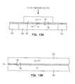
- FIGS. 13A and 13Bare an ABS view and a longitudinal cross-sectional view respectively of the fabrication of the read head portion of the head assembly in FIG. 6;
- FIGS. 14A and 14Bare the same as FIGS. 13A and 13B except the first pole piece in FIGS. 13A and 13B has been planarized, the write coil and insulation layer and the back gap have been constructed and a thick layer of alumina has been formed;
- FIGS. 15A and 15Bare the same as FIGS. 14A and 14B except the write coil and the thick alumina layer have been planarized and an isolation layer has been formed;
- FIGS. 16A and 16Bare the same as FIGS. 15A and 15B except a shaping layer has been formed;
- FIGS. 17A and 17Bare the same as FIGS. 16A and 16B except alumina has been deposited and planarized with respect to the shaping layer;
- FIGS. 18A and 18Bare the same as FIGS. 17A and 17B except a probe layer has been frame plated;
- FIGS. 19A and 19Bare the same as FIGS. 18A and 18B except alumina has been deposited and planarized with respect to the probe layer, a hard mask material layer has been formed and a photoresist layer has been formed with a desired track width;
- FIGS. 20A and 20Bare the same as FIGS. 19A and 19B except milling has been implemented to tranfer the image of the photoresist layer into the hard mask and ion milling has been implemented to remove the probe material layer on each side of the hard mask;
- FIGS. 21A and 21Bare the same as FIGS. 20A and 20B except the photoresist has been removed;
- FIGS. 22A, 22B and 22 Care ABS views of one embodiment of defining the track width of the probe at the ABS as shown in FIGS. 19A, 19B, 20 A and 20 B;
- FIGS. 23A, 23B, 23 C and 23 Dare ABS views of another embodiment of defining the track width of the probe as shown in FIGS. 19A, 19B, 20 A and 20 B.
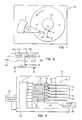
- FIGS. 1 - 3illustrate a magnetic disk drive 30 .
- the drive 30includes a spindle 32 that supports and rotates a magnetic disk 34 .
- the spindle 32is rotated by a spindle motor 36 that is controlled by a motor controller 38 .
- a slider 42has a combined read and write magnetic head 40 and is supported by a suspension 44 and actuator arm 46 that is rotatably positioned by an actuator 47 .
- a plurality of disks, sliders and suspensionsmay be employed in a large capacity direct access storage device (DASD) as shown in FIG. 3.
- the suspension 44 and actuator arm 46are moved by the actuator 47 to position the slider 42 so that the magnetic head 40 is in a transducing relationship with a surface of the magnetic disk 34 .
- DASDdirect access storage device
- the sliderWhen the disk 34 is rotated by the spindle motor 36 the slider is supported on a thin (typically, 0.05 ⁇ m) cushion of air (air bearing) between the surface of the disk 34 and the air bearing surface (ABS) 48 .
- the magnetic head 40may then be employed for writing information to multiple circular tracks on the surface of the disk 34 , as well as for reading information therefrom.
- Processing circuitry 50exchanges signals, representing such information, with the head 40 , provides spindle motor drive signals for rotating the magnetic disk 34 , and provides control signals to the actuator for moving the slider to various tracks.
- the slider 42In FIG. 4 the slider 42 is shown mounted to a suspension 44 .
- the components described hereinabovemay be mounted on a frame 54 of a housing 55 , as shown in FIG. 3.
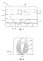
- FIG. 5is an ABS view of the slider 42 and the magnetic head 40 .
- the sliderhas a center rail 56 that supports the magnetic head 40 , and side rails 58 and 60 .
- the rails 56 , 58 and 60extend from a cross rail 62 .
- the cross rail 62is at a leading edge 64 of the slider and the magnetic head 40 is at a trailing edge 66 of the slider.
- FIG. 6is a side cross-sectional elevation view of a merged magnetic head assembly 40 , which includes a write head portion 70 and a read head portion 72 , the read head portion employing a read sensor 74 .
- FIG. 7is an ABS view of FIG. 6.
- the sensor 74is sandwiched between nonmagnetic electrically nonconductive first and second read gap layers 76 and 78 , and the read gap layers are sandwiched between ferromagnetic first and second shield layers 80 and 82 .
- a sense current I S(not shown) conducted through the sensor causes these resistance changes to be manifested as potential changes. These potential changes are then processed as readback signals by the processing circuitry 50 shown in FIG. 3.
- the write head portion 70includes first and second pole pieces 100 and 102 which extend from the ABS to back gap portions 104 and 106 which are recessed in the head and which are magnetically connected to a back gap layer 108 .
- an insulation stack 110which extends from the ABS to the back gap layer 108 and has embedded therein at least one write coil layer 112 .
- the insulation stack 110may have a bottom insulation layer 114 and insulation layers 116 and 118 which insulate the write coil layer from the second pole piece 102 , respectively.
- first and second solder connections 204 and 206connect leads from the spin valve sensor 74 to leads 212 and 214 on the suspension 44
- third and fourth solder connections 216 and 218connect leads 220 and 222 from the coil 84 (see FIG. 8) to leads 224 and 226 on the suspension.
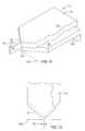
- the second pole piece 102includes a bottom ferromagnetic shaping layer 120 and a top ferromagnetic probe layer 122 .
- the shaping and probe layers 120 and 122have flare points 124 and 126 where the layers first commence to extend laterally outwardly after the ABS.
- the probe layer 122has a probe 128 and a yoke 130 wherein the yoke includes the flared portion and back gap portion 106 .
- the width of the top of the probe 128is the track width (TW) of the recording head.
- TWtrack width
- the probe 128is shown extended forward of the ABS since this is its configuration when it is partially constructed on a wafer where rows and columns of magnetic head assemblies are fabricated.
- the head assembliesare diced into rows of magnetic head assemblies and lapped to the ABS shown in FIG. 9. Each row of magnetic head assemblies is then diced into individual head assemblies and mounted on the suspensions, as shown in FIG. 3.
- the flare point 124 of the shaping layeris located between the ABS and the flare point 126 of the probe layer. In this manner the flare point 124 of the shaping layer is located close to the ABS, such as 0.25 ⁇ m to 1.5 ⁇ m from the ABS for 0.5 ⁇ m track widths for conducting the flux to the probe with a very short extension of the probe extending from the flare point 124 of the shaping layer to the ABS.
- FIGS. 11 and 12Another embodiment of a second pole piece 102 is illustrated in FIGS. 11 and 12 wherein the flare point 126 of the probe layer is located between the flare point 124 of the shaping layer and the ABS. While this is not a preferred arrangement of the present invention it is still within the spirit of the invention.
- an insulation layer 130is located between the flare point and forward portions of the shaping layer 120 and the ABS.
- the insulation layer 130is not a write gap layer as employed in a longitudinal recording head and therefore does not determine the linear bit density along the track of the rotating magnetic disk.
- the thickness or height of the probe 128determines the linear bit density since the flux signal magnetizes the bit cells in the recording disk in a perpendicular direction with the flux from the second pole piece returning to the first pole piece 100 via a soft magnetic layer in the perpendicular recording disk.
- the length of the head assembly 40 between the ABS and the back gap 108can be shortened so that the write coil frequency can be increased for further increasing the linear bit density of the write head.
- the magnetic head assemblymay include multiple write coil layers which are stacked one above the other instead of a single write coil layer, as shown in FIG. 6, and still be within the spirit of the invention.
- FIGS. 13A and 13B to FIGS. 21A and 21Billustrate various steps in the fabrication of the magnetic head assembly 40 shown in FIGS. 6 and 7.
- the first and second shield layers 80 and 82may be fabricated by well-known frame plating techniques and the first and second read gap layers 76 and 78 and the sensor 74 may be fabricated by well-known vacuum deposition techniques.
- the first shield layer 80has been planarized with an alumina layer 131 .
- FIGS. 14A and 14Ba thick layer of alumina is deposited (not shown) and planarized to layer 82 / 100 leaving an insulation layer 132 .
- the insulation layer 114 above the first shield/first pole piece layer 82 / 100is then formed.
- a back portion of the insulation layer 114is removed by ion milling (not shown) so that the back gap layer 108 can be frame plated.
- a photoresist layer 134is then formed on the write coil layer 112 and a thick alumina layer 136 is formed over the entire wafer.
- the waferis planarized to form the aforementioned insulation layers 116 and 118 leaving the back gap 108 exposed.
- the shaping layer 120is frame plated with the flare point 124 slightly recessed from the ABS and the back gap 106 magnetically connected to the back gap layer 108 .
- a thick layer of aluminais sputter deposited on the wafer and planarized to form layer 130 with its top surface coplanar with the top surface of the shaping layer 120 .
- the probe layer 122is frame plated with the probe layer having a probe material layer portion 138 which has a width which is wider than the desired track width of the write head. In contrast to that shown in FIGS.
- the probe layer 122may be full film plated without patterning the layer 122 to form layer portion 138 .
- the frame platingmay plate the probe 128 with the desired width to define the track width of the head.
- the subsequent method steps described hereinare preferred for defining a high resolution narrow probe 128 .
- a thick layer of aluminais sputter deposited on the wafer and planarized to form a layer 140 with its top surface coplanar with the top surface of the probe material layer portion 138 . This may also be accomplished with photoresist and then planarized in the same manner.
- a hard mask material layer 142such as carbon C, is then formed on the layers 138 and 140 .
- a photoresist mask 144is formed on top of the hard mask material layer 142 with a width equal to the desired track width of the write head.
- FIGS. 20A and 20Bthe image of the photoresist layer 144 is transferred to the hard mask layer. This is accomplished by oxygen reactive ion etching if the hard mask layer is carbon or reactive ion etching or ion milling if the hard mask layer is alumina. This removes all portions of the hard mask material layer except for a small hard mask portion 146 above the probe material layer with a width which is equal to the desired track width of the write head. Ion milling is then implemented with or without the photoresist layer 144 to remove portions of the probe material layer except for the desired probe 128 with the desired track width.
- FIGS. 21A and 21Bthe photoresist layer 144 has been removed and an overcoat layer 148 may be formed, as shown in FIG. 6.
- FIGS. 22 A- 22 Dillustrate one embodiment of forming the probe, as shown in FIGS. 19A, 19B, 20 A and 20 B.
- the probe material layer 138 , the alumina layer 140 , the hard mask material layer 142 and the photoresist layer 144have been formed, as shown in FIGS. 19A and 19B.
- ion milling or reactive ion etching (RIE)has been implemented while the wafer is rotated to remove the alumina layer 140 and portions of the hard mask layer 142 leaving the hard mask 146 and the photoresist layer 144 , as shown in FIGS. 20A and 20B.
- Oxygen reactive ion etchingis implemented if the hard mask material layer 142 is carbon. Slanted ion milling is then implemented at a preferred angle from 5° to 15° to a normal to the major plane of the hard mask layer 146 while the wafer is rotated which causes the probe 128 to have slanted side walls 150 and 152 which progressively decrease in width from a top surface 154 to a bottom surface 156 of the probe.
- This trapezoidal shape of the probe 128 at the ABSis a preferred probe configuration so as to minimize side writing when the probe is skewed at the outer and inner circular tracks of the rotating magnetic disk.
- FIG. 22Dthe photoresist layer 144 has been removed.
- FIGS. 23 A- 23 Dillustrate a slightly different embodiment for the construction of the probe as shown in FIGS. 19A, 19B, 20 A and 20 B.
- FIG. 23Ais the same as FIG. 22A.
- RIEreactive ion etching
- FIG. 23Cthe photoresist layer 144 has been removed and in FIG.
- the waferis subjected to slanted ion milling, preferably 5° to 15° to a normal to the major plane surface of the hard mask 146 while the wafer is rotated which forms the slanted side walls 150 and 152 of the probe 128 , as discussed hereinabove.
- slanted ion millingpreferably 5° to 15° to a normal to the major plane surface of the hard mask 146 while the wafer is rotated which forms the slanted side walls 150 and 152 of the probe 128 , as discussed hereinabove.
- the only difference between the steps shown in FIGS. 22 A- 22 D and the steps shown in FIGS. 23 A- 23 Cis that in FIGS. 23 A- 23 C the photoresist layer 144 is removed before ion milling the sloping side walls 150 and 152 .
- the trapezoidal shaped probe layercan be employed without the aforementioned shaping layer or the shaping layer may be employed without the trapezoidal shaped probe.
- the materials of the various layersare optional in some instances. For instance, photoresist may be employed in lieu of the alumina layers and vice versa.
- the magnetic headis planarized at various steps, planarization may occur only for the shaping and probe layers.
- the magnetic head assemblymay be a merged or piggyback head, as discussed hereinabove.
- the pole piecesare ferromagnetic materials and are preferably nickel iron.
- the shaping layermay be a different ferromagnetic material than the probe layer. For instance, the shaping layer may be Ni 45 Fe 55 and the probe layer may be Ni 83 Fe 17 .
Landscapes
- Engineering & Computer Science (AREA)
- Manufacturing & Machinery (AREA)
- Magnetic Heads (AREA)
Abstract
Description
- 1. Field of the Invention[0001]
- The present invention relates to a perpendicular recording write head with a ferromagnetic shaping layer and, more particularly, to such a write head wherein the shaping layer provides a planarized surface for the construction of a probe layer and supplies flux to a probe of the probe layer very close to an air bearing surface (ABS).[0002]
- 2. Description of the Related Art[0003]
- The heart of a computer is a magnetic disk drive which includes a rotating magnetic disk, a slider that has read and write heads, a suspension arm above the rotating disk and an actuator arm that swings the suspension arm to place the read and write heads over selected circular tracks on the rotating disk. The suspension arm urges the slider into contact with the surface of the disk when the disk is not rotating but, when the disk rotates, air is swirled by the rotating disk adjacent an air bearing surface (ABS) of the slider causing the slider to ride on an air bearing a slight distance from the surface of the rotating disk. When the slider rides on the air bearing the write and read heads are employed for writing magnetic impressions to and reading magnetic field signals from the rotating disk. The read and write heads are connected to processing circuitry that operates according to a computer program to implement the writing and reading functions.[0004]
- A write head typically employs ferromagnetic first and second pole pieces which are capable of carrying flux signals for the purpose of writing the magnetic impressions into the track. Each of the first and second pole pieces has a pole tip, a yoke and a back gap with the yoke being located between the pole tip and the back gap. The pole tips are located at the ABS and the back gaps are magnetically connected at a recessed location within the write head. At least one coil layer is embedded in an insulation stack between the yokes of the first and second pole pieces. A nonmagnetic write gap layer is located between the pole tips. Processing circuitry digitally energizes the write coil which induces flux signals into the first and second pole pieces. The flux signals bridge across the write gap layer at the ABS so as to write the aforementioned magnetic impressions or bits into the track of the rotating disk.[0005]
- The first and second pole pieces are typically fabricated by frame plating. Photoresist is employed to provide the frame and a seed layer is employed to provide a return path for the plating operation. A typical sequence for fabricating a pole piece is to sputter clean the wafer, sputter deposit a seed layer, such as nickel iron, on the wafer, spin a layer of photoresist on the wafer, light-image the photoresist layer through a mask to expose areas of the photoresist that are to be removed (assuming that the photoresist is a positive photoresist), develop the photoresist to remove the light-exposed areas to provide an opening in the photoresist and then plate the pole piece in the opening up to a desired height.[0006]
- A write head is typically rated by its areal density which is a product of its linear bit density and its track width density. The linear bit density is the number of bits which can be written per linear inch along the track of the rotating magnetic disk and the track width density is the number of tracks that can be written per inch along a radius of the rotating magnetic disk. The linear bit density is quantified as bits per inch (BPI) and the track width density is quantified as tracks per inch (TPI). The linear bit density depends upon the length of the bit along the track and the track width density is dependent upon the width of the second pole tip at the ABS. Efforts over the years to increase the areal density have resulted in computer storage capacities increasing from kilobytes to megabytes to gigabytes.[0007]
- The magnetic moment of each pole piece is parallel to the ABS and to the major planes of the layers of the write head. When the write current is applied to the coil of the write head the magnetic moment rotates toward or away from the ABS, depending upon whether the write signal is positive or negative. When the magnetic moment is rotated from the parallel position, the aforementioned magnetic flux fringes across the write gap layer between the first and second pole pieces impressing a positive or negative bit in the track of the rotating magnetic disk. As the write current frequency is increased, the linear bit density is also increased. An increase in the linear bit density is desirable in order to increase the aforementioned areal density which provides a computer with increased storage capacity.[0008]
- There are two types of magnetic write heads. One type is a longitudinal recording write head, which is described hereinabove, and the other type is a perpendicular recording write head. In the longitudinal recording write head the flux induced into the pole pieces by the write coil fringes across the write gap layer into the circular track of the rotating magnetic disk. This causes an orientation of the magnetization in the circular disk to be parallel to the plane of the disk which is referred to as longitudinal recording. The volume of the magnetization in the disk is referred to as a bit cell and the magnetizations in various bit cells are antiparallel so as to record information in digital form. The bit cell has a width representing track width, a length representing linear density and a depth which provides the volume necessary to provide sufficient magnetization to be read by a sensor of the read head. In longitudinal recording magnetic disks this depth is somewhat shallow. The length of the bit cell along the circular track of the disk is determined by the thickness of the write gap layer. A write gap layer is made as thin as practical so as to decrease the length of the bit cell along the track which increases the linear density of the recording. The width of the second pole tip of the longitudinal write head is also made as narrow as possible so as to reduce the track width and thereby increase the track width density. Unfortunately, the reduction in the thickness of the write gap layer and the track width is limited because the bit cell is shallow and there must be sufficient bit cell volume in order to produce sufficient magnetization in the recorded disk to be read by the sensor of the read head.[0009]
- In a perpendicular recording write head there is no write gap layer. In a perpendicular write head the second pole piece comprises a probe layer wherein the probe layer has a probe with a width that defines the track width of the write head and a wider yoke portion which delivers the flux to the probe. At a recessed end of the probe the yoke flares laterally outwardly to its fall width and thence to a back gap which is magnetically connected to a back gap of the first pole piece. The perpendicular write head records signals into a perpendicular recording magnetic disk which are significantly thicker than a longitudinal recording magnetic disk. In the perpendicular recording magnetic disk a soft magnetic layer underlies a thicker perpendicular recording layer which has a high saturation magnetization M[0010]Sand a high coercivity HC. The thicker disk permits a larger bit cell so that the length and the width of the cell can be decreased and still provide sufficient magnetization to be read by the read head. This means that the width and the thickness or height of the probe at the ABS can be reduced to increase the aforementioned TPI and BPI. The magnetization of the bit cell in a perpendicular recording scheme is perpendicular to the plane of the disk as contrasted to parallel to the plane of the disk in the longitudinal recording scheme. The flux from the probe is injected into the perpendicular recording magnetic disk in a direction perpendicular to the plane of the disk, thence parallel to the plane of the disk in the aforementioned soft magnetic underlayer and thence again perpendicular to the plane of the disk into the first pole piece to complete the magnetic circuit. It is now readily apparent that the width of the probe can be less than the width of the second pole tip of the longitudinal write head and the height or thickness of the probe can be less than the length of the longitudinal recorded bit cell so as to significantly increase the aforementioned areal density of the write head.
- The probe layer is typically constructed by the aforementioned frame plating in the same manner as construction of the second pole piece in a longitudinal recording head. It is desirable that the length of the probe between the ABS and a flare point of the probe layer, where the second pole first commences to widen after the ABS, be short so as to minimize a fully saturated probe length and thereby increase the write signal frequency so as to increase the linear density of the recording. Unfortunately, when the probe length is short it is difficult to fabricate a narrow width probe because of the loss of resolution of the probe in a region where the probe meets the flared portion of the probe layer. This can only be overcome by lengthening the probe which reduces the write frequency and the linear density of the recording head. This problem has been overcome by providing a ferromagnetic shaping layer immediately below the probe layer with a flare point which is located between the flare point of the probe layer and the ABS. In this manner the length of the probe may be sufficiently long so that the low resolution portion of the probe next to the flared portion of the probe layer is recessed and will not affect the resolution of the probe portion next to the ABS when frame plating is employed for its construction. The shaping layer can also be planarized with an insulation layer between the shaping layer and the ABS so as to provide a desirable planar surface for high resolution fabrication of the probe.[0011]
- Another aspect of the invention is to fabricate the probe with a narrow track width by a reverse imaging process. This reverse imaging process is another way to obtain high resolution fabrication of the probe even when the probe length is not increased to improve its resolution when constructed by frame plating, as discussed hereinabove. In the reverse imaging process frame plating is employed to fabricate the probe with a probe material layer that has a width larger than the desired track width of the write head. For instance, the probe material layer could be full film plated. A hard mask layer is formed on top of the probe material layer of a material such as carbon or alumina followed by formation of a resist layer on the hard mask layer with a width equal to the desired track width. Milling is then employed to remove exposed portions of the hard mask layer and then ion milling is employed to mill exposed portions of the probe material layer, thus defining the probe with the desired track width. In a preferred embodiment the ion milling is at an angle to a normal to the plane of the probe layer while the probe layer is rotated about the normal. This causes the side walls of the probe layer to be sloped inwardly from the top to the bottom of the probe. Accordingly, the probe is trapezoidal shaped at the ABS which minimizes side writing of the probe in tracks at the outer radius and inner radius of the rotating magnetic disk as the disk is rotated.[0012]
- An object of the present invention is to provide a more well-defined probe for a perpendicular recording head.[0013]
- Another object is to provide a probe with a sufficient length from the ABS into the head so that the probe can be well-defined by frame plating without reducing the write signal frequency.[0014]
- A further object is to construct a probe by a reverse imaging process which does not require the probe length to be lengthened in order to obtain a high resolution probe when constructed by frame plating.[0015]
- Still another object is to provide a reverse imaging process for constructing a probe with a trapezoidal shape at the ABS so as to minimize side writing.[0016]
- Still a further object is to provide a method of making each of the probes set forth hereinabove.[0017]
- Other objects and attendant advantages of the invention will be appreciated upon reading the following description taken together with the accompanying drawings.[0018]
- FIG. 1 is a plan view of an exemplary prior art magnetic disk drive;[0019]
- FIG. 2 is an end view of a prior art slider with a magnetic head of the disk drive as seen in plane[0020]2-2 of FIG. 1;
- FIG. 3 is an elevation view of the prior art magnetic disk drive wherein multiple disks and magnetic heads are employed;[0021]
- FIG. 4 is an isometric illustration of an exemplary prior art suspension system for supporting the slider and magnetic head;[0022]
- FIG. 5 is an ABS view of the magnetic head taken along plane[0023]5-5 of FIG. 2;
- FIG. 6 is a longitudinal cross-sectional view of the slider taken along plane[0024]6-6 of FIG. 2 showing the present perpendicular recording head in combination with a read head;
- FIG. 7 is an ABS view of the slider taken along plane[0025]7-7 of FIG. 6;
- FIG. 8 is a view taken along plane[0026]8-8 of FIG. 6 with all material above the coil layer and leads removed;
- FIG. 9 is an isometric view of a preferred second pole piece of FIG. 6 which includes a bottom shaping layer and a top probe layer;[0027]
- FIG. 10 is a top view of FIG. 9;[0028]
- FIG. 11 is an isometric view of another embodiment of the second pole piece of FIG. 6, the bottom shaping layer and the top probe layer;[0029]
- FIG. 12 is a top view of FIG. 11;[0030]
- FIGS. 13A and 13B are an ABS view and a longitudinal cross-sectional view respectively of the fabrication of the read head portion of the head assembly in FIG. 6;[0031]
- FIGS. 14A and 14B are the same as FIGS. 13A and 13B except the first pole piece in FIGS. 13A and 13B has been planarized, the write coil and insulation layer and the back gap have been constructed and a thick layer of alumina has been formed;[0032]
- FIGS. 15A and 15B are the same as FIGS. 14A and 14B except the write coil and the thick alumina layer have been planarized and an isolation layer has been formed;[0033]
- FIGS. 16A and 16B are the same as FIGS. 15A and 15B except a shaping layer has been formed;[0034]
- FIGS. 17A and 17B are the same as FIGS. 16A and 16B except alumina has been deposited and planarized with respect to the shaping layer;[0035]
- FIGS. 18A and 18B are the same as FIGS. 17A and 17B except a probe layer has been frame plated;[0036]
- FIGS. 19A and 19B are the same as FIGS. 18A and 18B except alumina has been deposited and planarized with respect to the probe layer, a hard mask material layer has been formed and a photoresist layer has been formed with a desired track width;[0037]
- FIGS. 20A and 20B are the same as FIGS. 19A and 19B except milling has been implemented to tranfer the image of the photoresist layer into the hard mask and ion milling has been implemented to remove the probe material layer on each side of the hard mask;[0038]
- FIGS. 21A and 21B are the same as FIGS. 20A and 20B except the photoresist has been removed;[0039]
- FIGS. 22A, 22B and[0040]22C are ABS views of one embodiment of defining the track width of the probe at the ABS as shown in FIGS. 19A, 19B,20A and20B; and
- FIGS. 23A, 23B,[0041]23C and23D are ABS views of another embodiment of defining the track width of the probe as shown in FIGS. 19A, 19B,20A and20B.
- Magnetic Disk Drive[0042]
- Referring now to the drawings wherein like reference numerals designate like or similar parts throughout the several views, FIGS.[0043]1-3 illustrate a
magnetic disk drive 30. Thedrive 30 includes aspindle 32 that supports and rotates amagnetic disk 34. Thespindle 32 is rotated by aspindle motor 36 that is controlled by amotor controller 38. Aslider 42 has a combined read and writemagnetic head 40 and is supported by asuspension 44 andactuator arm 46 that is rotatably positioned by anactuator 47. A plurality of disks, sliders and suspensions may be employed in a large capacity direct access storage device (DASD) as shown in FIG. 3. Thesuspension 44 andactuator arm 46 are moved by theactuator 47 to position theslider 42 so that themagnetic head 40 is in a transducing relationship with a surface of themagnetic disk 34. - When the[0044]
disk 34 is rotated by thespindle motor 36 the slider is supported on a thin (typically, 0.05 μm) cushion of air (air bearing) between the surface of thedisk 34 and the air bearing surface (ABS)48. Themagnetic head 40 may then be employed for writing information to multiple circular tracks on the surface of thedisk 34, as well as for reading information therefrom.Processing circuitry 50 exchanges signals, representing such information, with thehead 40, provides spindle motor drive signals for rotating themagnetic disk 34, and provides control signals to the actuator for moving the slider to various tracks. In FIG. 4 theslider 42 is shown mounted to asuspension 44. The components described hereinabove may be mounted on aframe 54 of ahousing 55, as shown in FIG. 3. - FIG. 5 is an ABS view of the[0045]
slider 42 and themagnetic head 40. The slider has acenter rail 56 that supports themagnetic head 40, andside rails rails cross rail 62. With respect to rotation of themagnetic disk 34, thecross rail 62 is at aleading edge 64 of the slider and themagnetic head 40 is at a trailingedge 66 of the slider. - FIG. 6 is a side cross-sectional elevation view of a merged[0046]
magnetic head assembly 40, which includes awrite head portion 70 and aread head portion 72, the read head portion employing aread sensor 74. FIG. 7 is an ABS view of FIG. 6. Thesensor 74 is sandwiched between nonmagnetic electrically nonconductive first and second read gap layers76 and78, and the read gap layers are sandwiched between ferromagnetic first and second shield layers80 and82. In response to external magnetic fields, the resistance of thesensor 74 changes. A sense current IS(not shown) conducted through the sensor causes these resistance changes to be manifested as potential changes. These potential changes are then processed as readback signals by theprocessing circuitry 50 shown in FIG. 3. - As shown in FIGS. 6 and 7, the[0047]
write head portion 70 includes first andsecond pole pieces gap portions back gap layer 108. Located between the first andsecond pole pieces insulation stack 110 which extends from the ABS to theback gap layer 108 and has embedded therein at least onewrite coil layer 112. Theinsulation stack 110 may have abottom insulation layer 114 andinsulation layers second pole piece 102, respectively. - Since the[0048]
second shield layer 82 and the firstpole piece layer 100 are a common layer this head is known as a merged head. In a piggyback head the second shield layer and the first pole piece layer are separate layers which are separated by a nonmagnetic layer. As shown in FIGS. 2 and 4, first andsecond solder connections spin valve sensor 74 to leads212 and214 on thesuspension 44, and third andfourth solder connections - As shown in FIGS. 9 and 10, the[0049]
second pole piece 102 includes a bottomferromagnetic shaping layer 120 and a topferromagnetic probe layer 122. The shaping and probelayers flare points probe layer 122 has aprobe 128 and ayoke 130 wherein the yoke includes the flared portion andback gap portion 106. The width of the top of theprobe 128 is the track width (TW) of the recording head. Theprobe 128 is shown extended forward of the ABS since this is its configuration when it is partially constructed on a wafer where rows and columns of magnetic head assemblies are fabricated. After completion of the magnetic head assemblies, which will be discussed hereinafter, the head assemblies are diced into rows of magnetic head assemblies and lapped to the ABS shown in FIG. 9. Each row of magnetic head assemblies is then diced into individual head assemblies and mounted on the suspensions, as shown in FIG. 3. In a preferred embodiment theflare point 124 of the shaping layer is located between the ABS and theflare point 126 of the probe layer. In this manner theflare point 124 of the shaping layer is located close to the ABS, such as 0.25 μm to 1.5 μm from the ABS for 0.5 μm track widths for conducting the flux to the probe with a very short extension of the probe extending from theflare point 124 of the shaping layer to the ABS. Accordingly, the very highly saturated portion of theprobe 128 is maintained short so that the write coil frequency can be increased to increase the linear density of the bits along the circular track of the rotating magnetic disk. Another embodiment of asecond pole piece 102 is illustrated in FIGS. 11 and 12 wherein theflare point 126 of the probe layer is located between theflare point 124 of the shaping layer and the ABS. While this is not a preferred arrangement of the present invention it is still within the spirit of the invention. - As shown in FIGS. 6 and 7, an[0050]
insulation layer 130 is located between the flare point and forward portions of theshaping layer 120 and the ABS. Theinsulation layer 130 is not a write gap layer as employed in a longitudinal recording head and therefore does not determine the linear bit density along the track of the rotating magnetic disk. In contrast, the thickness or height of theprobe 128 determines the linear bit density since the flux signal magnetizes the bit cells in the recording disk in a perpendicular direction with the flux from the second pole piece returning to thefirst pole piece 100 via a soft magnetic layer in the perpendicular recording disk. - It should be noted that when the[0051]
shaping layer 120 is employed, as shown in FIG. 9, the length of thehead assembly 40 between the ABS and theback gap 108 can be shortened so that the write coil frequency can be increased for further increasing the linear bit density of the write head. It should also be understood that the magnetic head assembly may include multiple write coil layers which are stacked one above the other instead of a single write coil layer, as shown in FIG. 6, and still be within the spirit of the invention. - Method of Making[0052]
- FIGS. 13A and 13B to FIGS. 21A and 21B illustrate various steps in the fabrication of the[0053]
magnetic head assembly 40 shown in FIGS. 6 and 7. In FIGS. 13A and 13B the first and second shield layers80 and82 may be fabricated by well-known frame plating techniques and the first and second read gap layers76 and78 and thesensor 74 may be fabricated by well-known vacuum deposition techniques. Thefirst shield layer 80 has been planarized with analumina layer 131. In FIGS. 14A and 14B a thick layer of alumina is deposited (not shown) and planarized to layer82/100 leaving aninsulation layer 132. Theinsulation layer 114 above the first shield/firstpole piece layer 82/100 is then formed. As shown in FIG. 14B, a back portion of theinsulation layer 114 is removed by ion milling (not shown) so that theback gap layer 108 can be frame plated. Aphotoresist layer 134 is then formed on thewrite coil layer 112 and athick alumina layer 136 is formed over the entire wafer. In FIGS. 15A and 15B the wafer is planarized to form the aforementioned insulation layers116 and118 leaving theback gap 108 exposed. - In FIGS. 16A and 16B the[0054]
shaping layer 120 is frame plated with theflare point 124 slightly recessed from the ABS and theback gap 106 magnetically connected to theback gap layer 108. In FIGS. 17A and 17B a thick layer of alumina is sputter deposited on the wafer and planarized to formlayer 130 with its top surface coplanar with the top surface of theshaping layer 120. In FIGS. 18A and 18B theprobe layer 122 is frame plated with the probe layer having a probematerial layer portion 138 which has a width which is wider than the desired track width of the write head. In contrast to that shown in FIGS. 18A and 18B, theprobe layer 122 may be full film plated without patterning thelayer 122 to formlayer portion 138. Optionally, the frame plating may plate theprobe 128 with the desired width to define the track width of the head. However, the subsequent method steps described herein are preferred for defining a high resolutionnarrow probe 128. In FIGS. 19A and 19B a thick layer of alumina is sputter deposited on the wafer and planarized to form alayer 140 with its top surface coplanar with the top surface of the probematerial layer portion 138. This may also be accomplished with photoresist and then planarized in the same manner. A hardmask material layer 142, such as carbon C, is then formed on thelayers photoresist mask 144 is formed on top of the hardmask material layer 142 with a width equal to the desired track width of the write head. - In FIGS. 20A and 20B the image of the[0055]
photoresist layer 144 is transferred to the hard mask layer. This is accomplished by oxygen reactive ion etching if the hard mask layer is carbon or reactive ion etching or ion milling if the hard mask layer is alumina. This removes all portions of the hard mask material layer except for a smallhard mask portion 146 above the probe material layer with a width which is equal to the desired track width of the write head. Ion milling is then implemented with or without thephotoresist layer 144 to remove portions of the probe material layer except for the desiredprobe 128 with the desired track width. In FIGS. 21A and 21B thephotoresist layer 144 has been removed and anovercoat layer 148 may be formed, as shown in FIG. 6. - FIGS.[0056]22A-22D illustrate one embodiment of forming the probe, as shown in FIGS. 19A, 19B,20A and20B. In FIG. 22A the
probe material layer 138, thealumina layer 140, the hardmask material layer 142 and thephotoresist layer 144 have been formed, as shown in FIGS. 19A and 19B. In FIG. 22B ion milling or reactive ion etching (RIE) has been implemented while the wafer is rotated to remove thealumina layer 140 and portions of thehard mask layer 142 leaving thehard mask 146 and thephotoresist layer 144, as shown in FIGS. 20A and 20B. Oxygen reactive ion etching is implemented if the hardmask material layer 142 is carbon. Slanted ion milling is then implemented at a preferred angle from 5° to 15° to a normal to the major plane of thehard mask layer 146 while the wafer is rotated which causes theprobe 128 to have slantedside walls top surface 154 to abottom surface 156 of the probe. This trapezoidal shape of theprobe 128 at the ABS is a preferred probe configuration so as to minimize side writing when the probe is skewed at the outer and inner circular tracks of the rotating magnetic disk. In FIG. 22D thephotoresist layer 144 has been removed. - FIGS.[0057]23A-23D illustrate a slightly different embodiment for the construction of the probe as shown in FIGS. 19A, 19B,20A and20B. FIG. 23A is the same as FIG. 22A. In FIG. 23B ion milling or reactive ion etching (RIE) has been implemented to remove portions of the hard
mask material layer 142 except for thehard mask portion 146 which has a width equal to the desired track width of the write head. In FIG. 23C thephotoresist layer 144 has been removed and in FIG. 23D the wafer is subjected to slanted ion milling, preferably 5° to 15° to a normal to the major plane surface of thehard mask 146 while the wafer is rotated which forms the slantedside walls probe 128, as discussed hereinabove. The only difference between the steps shown in FIGS.22A-22D and the steps shown in FIGS.23A-23C is that in FIGS.23A-23C thephotoresist layer 144 is removed before ion milling thesloping side walls - Discussion[0058]
- It should be understood that vacuum deposition may be employed in lieu of the aforementioned frame plating step. Further, in a broad concept of the invention the trapezoidal shaped probe layer can be employed without the aforementioned shaping layer or the shaping layer may be employed without the trapezoidal shaped probe. The materials of the various layers are optional in some instances. For instance, photoresist may be employed in lieu of the alumina layers and vice versa. Further, while the magnetic head is planarized at various steps, planarization may occur only for the shaping and probe layers. Further, the magnetic head assembly may be a merged or piggyback head, as discussed hereinabove. The pole pieces are ferromagnetic materials and are preferably nickel iron. It should be noted that with the invention the shaping layer may be a different ferromagnetic material than the probe layer. For instance, the shaping layer may be Ni[0059]45Fe55and the probe layer may be Ni83Fe17.
- Clearly, other embodiments and modifications of this invention will occur readily to those of ordinary skill in the art in view of these teachings. Therefore, this invention is to be limited only by the following claims, which include all such embodiments and modifications when viewed in conjunction with the above specification and accompanying drawings.[0060]
Claims (41)
Priority Applications (1)
| Application Number | Priority Date | Filing Date | Title |
|---|---|---|---|
| US10/054,553US6757141B2 (en) | 2002-01-18 | 2002-01-18 | Perpendicular recording write head with a ferromagnetic shaping layer |
Applications Claiming Priority (1)
| Application Number | Priority Date | Filing Date | Title |
|---|---|---|---|
| US10/054,553US6757141B2 (en) | 2002-01-18 | 2002-01-18 | Perpendicular recording write head with a ferromagnetic shaping layer |
Publications (2)
| Publication Number | Publication Date |
|---|---|
| US20030137779A1true US20030137779A1 (en) | 2003-07-24 |
| US6757141B2 US6757141B2 (en) | 2004-06-29 |
Family
ID=21991898
Family Applications (1)
| Application Number | Title | Priority Date | Filing Date |
|---|---|---|---|
| US10/054,553Expired - Fee RelatedUS6757141B2 (en) | 2002-01-18 | 2002-01-18 | Perpendicular recording write head with a ferromagnetic shaping layer |
Country Status (1)
| Country | Link |
|---|---|
| US (1) | US6757141B2 (en) |
Cited By (13)
| Publication number | Priority date | Publication date | Assignee | Title |
|---|---|---|---|---|
| US20040223257A1 (en)* | 2003-05-06 | 2004-11-11 | Hitachi Global Storage Technologies | Write first design for a perpendicular thin film head |
| US20040223258A1 (en)* | 2003-05-07 | 2004-11-11 | Hitachi Global Storage Technologies Netherlands B.V. | Method and apparatus for providing a truncated profile probe for perpendicular recording |
| US20050024770A1 (en)* | 2003-08-01 | 2005-02-03 | Headway Technologies, Inc. | Low DC coil resistance planar writer |
| US20050024760A1 (en)* | 2003-07-30 | 2005-02-03 | Hitachi Global Storage Technologies, Inc. | Perpendicular recording and read head assembly with in situ stand alone stabilizer for a magnetic medium underlayer |
| US20060002020A1 (en)* | 2003-07-09 | 2006-01-05 | Seagate Technology Llc | Recording head for reducing side track erasure |
| US20060002016A1 (en)* | 2004-06-30 | 2006-01-05 | Vladimir Nikitin | Method and apparatus for processing sub-micron write head flare definition |
| US20060044681A1 (en)* | 2004-08-31 | 2006-03-02 | Quang Le | Write pole and method of manufacturing the same |
| US20060044682A1 (en)* | 2004-08-31 | 2006-03-02 | Quang Le | Self aligned wrap around shield for perpendicular magnetic recording |
| US20060256473A1 (en)* | 2005-04-28 | 2006-11-16 | Samsung Electronics Co., Ltd. | Perpendicular magnetic recording head |
| US20070247750A1 (en)* | 2006-04-25 | 2007-10-25 | Hitachi Global Storage Technologies | Magnetic write head design for reducing temperature induced protrusion |
| US20080117546A1 (en)* | 2006-11-16 | 2008-05-22 | Hitachi Global Storage Technologies Netherlands B.V. | Perpendicular magnetic recording write head with flux-conductor contacting write pole |
| US7881010B2 (en) | 2007-12-13 | 2011-02-01 | Hitachi Global Storage Technologies Netherlands B.V. | Process for self-aligned flare point and shield throat definition prior to main pole patterning |
| US8964331B2 (en)* | 2012-06-21 | 2015-02-24 | HGST Netherlands B.V. | Perpendicular magnetic write head having a main magnetic write pole portion and a magnetic sub-pole portion configured for increased magnetic write field |
Families Citing this family (26)
| Publication number | Priority date | Publication date | Assignee | Title |
|---|---|---|---|---|
| US7061719B2 (en)* | 2002-10-01 | 2006-06-13 | Tdk Corporation | Thin film magnetic head and method of manufacturing the same |
| US7119988B2 (en)* | 2003-04-01 | 2006-10-10 | Hitachi Global Storage Technologies Netherlands, B.V. | Perpendicular magnetic head having modified shaping layer for direct plating of magnetic pole piece |
| US7583477B2 (en)* | 2003-06-30 | 2009-09-01 | Seagate Technology Llc | Magnetic recording head with a point writer pole |
| US7102854B2 (en)* | 2003-10-03 | 2006-09-05 | Seagate Technology Llc | Transducing head with reduced side writing |
| JP2005216361A (en)* | 2004-01-28 | 2005-08-11 | Hitachi Global Storage Technologies Netherlands Bv | Magnetic head and manufacturing method thereof |
| US7271982B2 (en)* | 2004-02-13 | 2007-09-18 | Hitachi Global Storage Technologies Netherlands B.V. | Perpendicular magnetic recording head built using an air-bearing surface damascene process |
| US7505226B2 (en)* | 2004-05-28 | 2009-03-17 | Hitachi Global Storage Technologies Netherlands Bv | Method and apparatus for providing a pole tip structure having a shape for preventing over saturation of the pole tip structure |
| US7440229B2 (en)* | 2004-06-18 | 2008-10-21 | Headway Technologies, Inc. | Thin-film magnetic head having a write shield layer |
| US7580222B2 (en)* | 2004-06-18 | 2009-08-25 | Headway Technologies, Inc. | Thin-film magnetic head, a head gimbal assembly and hard disk drive |
| US7296339B1 (en) | 2004-09-08 | 2007-11-20 | Western Digital (Fremont), Llc | Method for manufacturing a perpendicular magnetic recording head |
| JP3949149B2 (en)* | 2004-11-08 | 2007-07-25 | Tdk株式会社 | Perpendicular magnetic recording head and magnetic recording apparatus |
| US7633713B2 (en)* | 2005-01-31 | 2009-12-15 | Hitachi Global Storage Technologies Netherlands B.V. | Method for controlling the formation of the trailing shield gap during perpendicular head fabrication and head formed thereby |
| JP2006302421A (en)* | 2005-04-21 | 2006-11-02 | Hitachi Global Storage Technologies Netherlands Bv | Magnetic head manufacturing method and magnetic head |
| US7599152B2 (en)* | 2005-04-28 | 2009-10-06 | Headway Technologies, Inc. | Magnetic read-write head shield that prevents flux concentration at edges close to the ABS |
| US20060245113A1 (en)* | 2005-04-28 | 2006-11-02 | Headway Technologies, Inc. | Method to reduce sensitivity of a perpendicular recording head to external fields |
| US7552523B1 (en) | 2005-07-01 | 2009-06-30 | Western Digital (Fremont), Llc | Method for manufacturing a perpendicular magnetic recording transducer |
| US8333008B1 (en) | 2005-07-29 | 2012-12-18 | Western Digital (Fremont), Llc | Method for manufacturing a perpendicular magnetic recording transducer |
| US7508627B1 (en) | 2006-03-03 | 2009-03-24 | Western Digital (Fremont), Llc | Method and system for providing perpendicular magnetic recording transducers |
| US8141235B1 (en) | 2006-06-09 | 2012-03-27 | Western Digital (Fremont), Llc | Method for manufacturing a perpendicular magnetic recording transducers |
| US7530159B2 (en)* | 2006-06-29 | 2009-05-12 | Hitachi Global Storage Technologies Netherlands B.V. | Method of distortion correction in shrink processes for fabrication of write poles |
| US7612963B2 (en)* | 2006-06-30 | 2009-11-03 | Hitachi Global Storage Technologies Netherlands B.V. | Perpendicular magnetic recording head with photoresist dam between write coil and air bearing surface |
| US7757380B2 (en)* | 2006-11-10 | 2010-07-20 | Hitachi Global Storage Technologies Netherlands B.V. | Methods for the manufacture of notched trailing shields |
| US8015692B1 (en) | 2007-11-07 | 2011-09-13 | Western Digital (Fremont), Llc | Method for providing a perpendicular magnetic recording (PMR) head |
| US9099118B1 (en) | 2009-05-26 | 2015-08-04 | Western Digital (Fremont), Llc | Dual damascene process for producing a PMR write pole |
| US8486285B2 (en) | 2009-08-20 | 2013-07-16 | Western Digital (Fremont), Llc | Damascene write poles produced via full film plating |
| US8837084B2 (en) | 2012-11-29 | 2014-09-16 | HGST Netherlands B.V. | Perpendicular magnetic write head having a hull shaped stitched pole |
Citations (5)
| Publication number | Priority date | Publication date | Assignee | Title |
|---|---|---|---|---|
| US20020024765A1 (en)* | 2000-08-29 | 2002-02-28 | Fujitsu Limited | Thin film magnetic head and magnetic head assembly employing the same |
| US20020026704A1 (en)* | 1998-03-20 | 2002-03-07 | Stageberg Frank E. | Method for forming a narrow track inductive write head having two-piece pole |
| US20020034043A1 (en)* | 2000-09-18 | 2002-03-21 | Tomohiro Okada | Single pole type recording head and magnetic storage apparatus |
| US20020176214A1 (en)* | 2001-05-23 | 2002-11-28 | Shukh Alexander M. | Writer for perpendicular recording with controlled write width |
| US6504675B1 (en)* | 2000-01-12 | 2003-01-07 | Seagate Technology Llc | Perpendicular magnetic recording heads with write pole shaped to reduce skew effects during writing |
Family Cites Families (10)
| Publication number | Priority date | Publication date | Assignee | Title |
|---|---|---|---|---|
| US4404609A (en) | 1981-10-30 | 1983-09-13 | International Business Machines Corporation | Thin film inductive transducer for perpendicular recording |
| JPH01133212A (en)* | 1987-04-10 | 1989-05-25 | Hitachi Ltd | Thin film magnetic head and its manufacturing method |
| JPH01133211A (en)* | 1987-06-16 | 1989-05-25 | Hitachi Ltd | Thin film magnetic head and its manufacturing method |
| JPS6478451A (en)* | 1987-09-18 | 1989-03-23 | Victor Company Of Japan | Vertical magnetic head with electrode |
| JPH081687B2 (en) | 1988-09-27 | 1996-01-10 | 富士通株式会社 | Perpendicular magnetization thin film head |
| US5225953A (en) | 1989-11-09 | 1993-07-06 | Sumitomo Special Metal Co., Ltd. | Magnetic thin film head of a single magnetic pole for perpendicular recording and reproduction |
| US6285528B1 (en) | 1993-03-15 | 2001-09-04 | Kabushiki Kaisha Toshiba | Thin-film magnetic head |
| US6072669A (en) | 1997-03-21 | 2000-06-06 | Indeck; Ronald S. | Thin film magnetic write head with preconditioning gap |
| JP3410045B2 (en)* | 1999-05-26 | 2003-05-26 | アルプス電気株式会社 | Method for manufacturing thin-film magnetic head |
| JP3576067B2 (en)* | 2000-03-30 | 2004-10-13 | 株式会社東芝 | Method of manufacturing magnetic recording head |
- 2002
- 2002-01-18USUS10/054,553patent/US6757141B2/ennot_activeExpired - Fee Related
Patent Citations (5)
| Publication number | Priority date | Publication date | Assignee | Title |
|---|---|---|---|---|
| US20020026704A1 (en)* | 1998-03-20 | 2002-03-07 | Stageberg Frank E. | Method for forming a narrow track inductive write head having two-piece pole |
| US6504675B1 (en)* | 2000-01-12 | 2003-01-07 | Seagate Technology Llc | Perpendicular magnetic recording heads with write pole shaped to reduce skew effects during writing |
| US20020024765A1 (en)* | 2000-08-29 | 2002-02-28 | Fujitsu Limited | Thin film magnetic head and magnetic head assembly employing the same |
| US20020034043A1 (en)* | 2000-09-18 | 2002-03-21 | Tomohiro Okada | Single pole type recording head and magnetic storage apparatus |
| US20020176214A1 (en)* | 2001-05-23 | 2002-11-28 | Shukh Alexander M. | Writer for perpendicular recording with controlled write width |
Cited By (26)
| Publication number | Priority date | Publication date | Assignee | Title |
|---|---|---|---|---|
| US7969683B2 (en)* | 2003-05-06 | 2011-06-28 | Hitachi Global Storage Technologies Netherlands B.V. | Write first design for a perpendicular thin film head |
| US20040223257A1 (en)* | 2003-05-06 | 2004-11-11 | Hitachi Global Storage Technologies | Write first design for a perpendicular thin film head |
| US20040223258A1 (en)* | 2003-05-07 | 2004-11-11 | Hitachi Global Storage Technologies Netherlands B.V. | Method and apparatus for providing a truncated profile probe for perpendicular recording |
| US7768742B2 (en)* | 2003-05-07 | 2010-08-03 | Hitachi Global Storage Technologies Netherlands B.V. | Method and apparatus for providing a truncated profile probe for perpendicular recording |
| US20090251827A9 (en)* | 2003-07-09 | 2009-10-08 | Seagate Technology Llc | Recording head for reducing side track erasure |
| US20060002020A1 (en)* | 2003-07-09 | 2006-01-05 | Seagate Technology Llc | Recording head for reducing side track erasure |
| US7684150B2 (en) | 2003-07-09 | 2010-03-23 | Seagate Technology Llc | Recording head for reducing side track erasure |
| US6985322B2 (en)* | 2003-07-30 | 2006-01-10 | Hitachi Global Storage Technologies Netherlands B.V. | Perpendicular recording and read head assembly with in situ stand alone stabilizer for a magnetic medium underlayer |
| US20050024760A1 (en)* | 2003-07-30 | 2005-02-03 | Hitachi Global Storage Technologies, Inc. | Perpendicular recording and read head assembly with in situ stand alone stabilizer for a magnetic medium underlayer |
| US20050024770A1 (en)* | 2003-08-01 | 2005-02-03 | Headway Technologies, Inc. | Low DC coil resistance planar writer |
| US20090095707A1 (en)* | 2004-06-30 | 2009-04-16 | Hitachi Global Storage Technologies Netherlands B.V. | Method And Apparatus For Processing Sub-Micron Write Head Flare Definition |
| US20060002016A1 (en)* | 2004-06-30 | 2006-01-05 | Vladimir Nikitin | Method and apparatus for processing sub-micron write head flare definition |
| US7870659B2 (en)* | 2004-06-30 | 2011-01-18 | Hitachi Global Storage Technologies Netherlands B.V. | Method for defining a perpendicular magnetic head |
| US7692893B2 (en)* | 2004-06-30 | 2010-04-06 | Hitachi Global Storage Technologies Netherlands, B.V. | Side-by-side magnetic head configuration with flared pole tip layer and read sensor sharing same plane |
| US7649712B2 (en) | 2004-08-31 | 2010-01-19 | Hitachi Global Storage Technologies Netherlands B.V. | Self aligned wrap around shield for perpendicular magnetic recording |
| US20060044681A1 (en)* | 2004-08-31 | 2006-03-02 | Quang Le | Write pole and method of manufacturing the same |
| US7565732B2 (en) | 2004-08-31 | 2009-07-28 | Hitachi Global Storage Technologies Netherlands B.V. | Method of manufacturing a write pole |
| US20060044682A1 (en)* | 2004-08-31 | 2006-03-02 | Quang Le | Self aligned wrap around shield for perpendicular magnetic recording |
| US20060256473A1 (en)* | 2005-04-28 | 2006-11-16 | Samsung Electronics Co., Ltd. | Perpendicular magnetic recording head |
| US8098456B2 (en)* | 2005-04-28 | 2012-01-17 | Samsung Electronics Co., Ltd. | Perpendicular magnetic recording head having a tapered main pole |
| US7593183B2 (en)* | 2006-04-25 | 2009-09-22 | Hitachi Global Storage Technologies Netherlands B.V. | Magnetic write head design for reducing temperature induced protrusion |
| US20070247750A1 (en)* | 2006-04-25 | 2007-10-25 | Hitachi Global Storage Technologies | Magnetic write head design for reducing temperature induced protrusion |
| US20080117546A1 (en)* | 2006-11-16 | 2008-05-22 | Hitachi Global Storage Technologies Netherlands B.V. | Perpendicular magnetic recording write head with flux-conductor contacting write pole |
| US7558019B2 (en)* | 2006-11-16 | 2009-07-07 | Hitachi Global Storage Technologies Netherlands B.V. | Perpendicular magnetic recording write head with flux-conductor contacting write pole |
| US7881010B2 (en) | 2007-12-13 | 2011-02-01 | Hitachi Global Storage Technologies Netherlands B.V. | Process for self-aligned flare point and shield throat definition prior to main pole patterning |
| US8964331B2 (en)* | 2012-06-21 | 2015-02-24 | HGST Netherlands B.V. | Perpendicular magnetic write head having a main magnetic write pole portion and a magnetic sub-pole portion configured for increased magnetic write field |
Also Published As
| Publication number | Publication date |
|---|---|
| US6757141B2 (en) | 2004-06-29 |
Similar Documents
| Publication | Publication Date | Title |
|---|---|---|
| US6757141B2 (en) | Perpendicular recording write head with a ferromagnetic shaping layer | |
| US7031121B2 (en) | Perpendicular recording magnetic head with a write shield magnetically coupled to a first pole piece | |
| US7024756B2 (en) | Method of making a perpendicular recording magnetic head pole tip with an etchable adhesion CMP stop layer | |
| US6693769B2 (en) | High data rate write head | |
| US7969684B2 (en) | Write head design and method for reducing adjacent track interference at very narrow track widths | |
| US7712206B2 (en) | Method for manufacturing a magnetic write head having a trailing shield with an accurately controlled trailing shield gap thickness | |
| US6857181B2 (en) | Method of making a T-shaped write head with less side writing | |
| US6628478B2 (en) | Write head with all metallic laminated pole pieces with thickness differential | |
| US6134080A (en) | Magnetic head with precisely defined zero throat height | |
| US7593183B2 (en) | Magnetic write head design for reducing temperature induced protrusion | |
| US6680830B2 (en) | Tunnel valve sensor and flux guide with improved flux transfer therebetween | |
| US7716812B2 (en) | Method of manufacturing a magnetic head | |
| US6722018B2 (en) | Method of forming a second pole piece of a write head | |
| US20030135987A1 (en) | Method of making a narrow pole tip by ion beam deposition | |
| US20020191350A1 (en) | Protection of second pole tip thickness during fabrication of a write head | |
| US8268407B2 (en) | Method for manufacturing a perpendicular magnetic write head having write pole | |
| US7788798B2 (en) | Method for manufacturing a perpendicular magnetic write head with wrap around magnetic trailing and side shields | |
| US7259941B2 (en) | Magnetoresistive sensor having a high coercivity hard bias structure | |
| US8031434B2 (en) | Hybrid, self aligned magnetic write head with a partially plated pole and method of producing same | |
| US7130153B2 (en) | Stitched write head with staircase P2 defined throat height | |
| US20050024780A1 (en) | Method of reducing shield shorts in a high linear density read head with a contiguous junction | |
| US7483246B2 (en) | Magnetic sensor having a seedlayer for providing improved hard magnet properties |
Legal Events
| Date | Code | Title | Description |
|---|---|---|---|
| AS | Assignment | Owner name:INTERNATIONAL BUSINESS MACHINES CORPORATION, NEW Y Free format text:ASSIGNMENT OF ASSIGNORS INTEREST;ASSIGNORS:SANTINI, HUGO ALBERTO EMILIO;WILLIAMS, MASON LAMAR;REEL/FRAME:012575/0981 Effective date:20011128 | |
| AS | Assignment | Owner name:HITACHI GLOBAL STORAGE TECHNOLOGIES NETHERLANDS B. Free format text:ASSIGNMENT OF ASSIGNORS INTEREST;ASSIGNOR:INTERNATIONAL BUSINESS MACHINES CORPORATION;REEL/FRAME:014045/0208 Effective date:20030811 | |
| FEPP | Fee payment procedure | Free format text:PAYOR NUMBER ASSIGNED (ORIGINAL EVENT CODE: ASPN); ENTITY STATUS OF PATENT OWNER: LARGE ENTITY | |
| CC | Certificate of correction | ||
| FEPP | Fee payment procedure | Free format text:PAYER NUMBER DE-ASSIGNED (ORIGINAL EVENT CODE: RMPN); ENTITY STATUS OF PATENT OWNER: LARGE ENTITY Free format text:PAYOR NUMBER ASSIGNED (ORIGINAL EVENT CODE: ASPN); ENTITY STATUS OF PATENT OWNER: LARGE ENTITY | |
| FPAY | Fee payment | Year of fee payment:4 | |
| FPAY | Fee payment | Year of fee payment:8 | |
| AS | Assignment | Owner name:HGST, NETHERLANDS B.V., NETHERLANDS Free format text:CHANGE OF NAME;ASSIGNOR:HGST, NETHERLANDS B.V.;REEL/FRAME:029341/0777 Effective date:20120723 Owner name:HGST NETHERLANDS B.V., NETHERLANDS Free format text:CHANGE OF NAME;ASSIGNOR:HITACHI GLOBAL STORAGE TECHNOLOGIES NETHERLANDS B.V.;REEL/FRAME:029341/0777 Effective date:20120723 | |
| REMI | Maintenance fee reminder mailed | ||
| LAPS | Lapse for failure to pay maintenance fees | ||
| STCH | Information on status: patent discontinuation | Free format text:PATENT EXPIRED DUE TO NONPAYMENT OF MAINTENANCE FEES UNDER 37 CFR 1.362 | |
| FP | Lapsed due to failure to pay maintenance fee | Effective date:20160629 |