US20030128018A1 - Methods for regulation of power converters using primary-only feedback - Google Patents
Methods for regulation of power converters using primary-only feedbackDownload PDFInfo
- Publication number
- US20030128018A1 US20030128018A1US10/306,780US30678002AUS2003128018A1US 20030128018 A1US20030128018 A1US 20030128018A1US 30678002 AUS30678002 AUS 30678002AUS 2003128018 A1US2003128018 A1US 2003128018A1
- Authority
- US
- United States
- Prior art keywords
- switch
- converter
- cycle
- pulse
- voltage
- Prior art date
- Legal status (The legal status is an assumption and is not a legal conclusion. Google has not performed a legal analysis and makes no representation as to the accuracy of the status listed.)
- Granted
Links
- 238000000034methodMethods0.000titleclaimsabstractdescription55
- 230000001351cycling effectEffects0.000claimsabstractdescription18
- 230000004044responseEffects0.000claimsabstractdescription18
- 230000001105regulatory effectEffects0.000claimsabstractdescription12
- 230000001276controlling effectEffects0.000claimsabstractdescription8
- 238000004804windingMethods0.000claimsdescription30
- 230000004907fluxEffects0.000claimsdescription15
- 230000010355oscillationEffects0.000claimsdescription11
- 238000005070samplingMethods0.000description11
- 230000007704transitionEffects0.000description7
- 238000012546transferMethods0.000description5
- 238000010586diagramMethods0.000description4
- 230000004913activationEffects0.000description3
- 239000003990capacitorSubstances0.000description3
- 238000005457optimizationMethods0.000description3
- 230000008901benefitEffects0.000description2
- 238000002955isolationMethods0.000description2
- 238000005259measurementMethods0.000description2
- 230000008569processEffects0.000description2
- 230000002411adverseEffects0.000description1
- 230000005540biological transmissionEffects0.000description1
- 230000008859changeEffects0.000description1
- 238000006243chemical reactionMethods0.000description1
- 230000008034disappearanceEffects0.000description1
- 230000005669field effectEffects0.000description1
- 238000001914filtrationMethods0.000description1
- 230000003116impacting effectEffects0.000description1
- 238000010348incorporationMethods0.000description1
- 238000012986modificationMethods0.000description1
- 230000004048modificationEffects0.000description1
- 230000003071parasitic effectEffects0.000description1
- 238000012552reviewMethods0.000description1
Images


Classifications
- H—ELECTRICITY
- H02—GENERATION; CONVERSION OR DISTRIBUTION OF ELECTRIC POWER
- H02M—APPARATUS FOR CONVERSION BETWEEN AC AND AC, BETWEEN AC AND DC, OR BETWEEN DC AND DC, AND FOR USE WITH MAINS OR SIMILAR POWER SUPPLY SYSTEMS; CONVERSION OF DC OR AC INPUT POWER INTO SURGE OUTPUT POWER; CONTROL OR REGULATION THEREOF
- H02M3/00—Conversion of DC power input into DC power output
- H02M3/02—Conversion of DC power input into DC power output without intermediate conversion into AC
- H02M3/04—Conversion of DC power input into DC power output without intermediate conversion into AC by static converters
- H02M3/10—Conversion of DC power input into DC power output without intermediate conversion into AC by static converters using discharge tubes with control electrode or semiconductor devices with control electrode
- H02M3/145—Conversion of DC power input into DC power output without intermediate conversion into AC by static converters using discharge tubes with control electrode or semiconductor devices with control electrode using devices of a triode or transistor type requiring continuous application of a control signal
- H02M3/155—Conversion of DC power input into DC power output without intermediate conversion into AC by static converters using discharge tubes with control electrode or semiconductor devices with control electrode using devices of a triode or transistor type requiring continuous application of a control signal using semiconductor devices only
- H02M3/156—Conversion of DC power input into DC power output without intermediate conversion into AC by static converters using discharge tubes with control electrode or semiconductor devices with control electrode using devices of a triode or transistor type requiring continuous application of a control signal using semiconductor devices only with automatic control of output voltage or current, e.g. switching regulators
- H02M3/157—Conversion of DC power input into DC power output without intermediate conversion into AC by static converters using discharge tubes with control electrode or semiconductor devices with control electrode using devices of a triode or transistor type requiring continuous application of a control signal using semiconductor devices only with automatic control of output voltage or current, e.g. switching regulators with digital control
- H—ELECTRICITY
- H02—GENERATION; CONVERSION OR DISTRIBUTION OF ELECTRIC POWER
- H02M—APPARATUS FOR CONVERSION BETWEEN AC AND AC, BETWEEN AC AND DC, OR BETWEEN DC AND DC, AND FOR USE WITH MAINS OR SIMILAR POWER SUPPLY SYSTEMS; CONVERSION OF DC OR AC INPUT POWER INTO SURGE OUTPUT POWER; CONTROL OR REGULATION THEREOF
- H02M3/00—Conversion of DC power input into DC power output
- H02M3/02—Conversion of DC power input into DC power output without intermediate conversion into AC
- H02M3/04—Conversion of DC power input into DC power output without intermediate conversion into AC by static converters
- H02M3/10—Conversion of DC power input into DC power output without intermediate conversion into AC by static converters using discharge tubes with control electrode or semiconductor devices with control electrode
- H02M3/145—Conversion of DC power input into DC power output without intermediate conversion into AC by static converters using discharge tubes with control electrode or semiconductor devices with control electrode using devices of a triode or transistor type requiring continuous application of a control signal
- H02M3/155—Conversion of DC power input into DC power output without intermediate conversion into AC by static converters using discharge tubes with control electrode or semiconductor devices with control electrode using devices of a triode or transistor type requiring continuous application of a control signal using semiconductor devices only
- H02M3/156—Conversion of DC power input into DC power output without intermediate conversion into AC by static converters using discharge tubes with control electrode or semiconductor devices with control electrode using devices of a triode or transistor type requiring continuous application of a control signal using semiconductor devices only with automatic control of output voltage or current, e.g. switching regulators
- H—ELECTRICITY
- H02—GENERATION; CONVERSION OR DISTRIBUTION OF ELECTRIC POWER
- H02M—APPARATUS FOR CONVERSION BETWEEN AC AND AC, BETWEEN AC AND DC, OR BETWEEN DC AND DC, AND FOR USE WITH MAINS OR SIMILAR POWER SUPPLY SYSTEMS; CONVERSION OF DC OR AC INPUT POWER INTO SURGE OUTPUT POWER; CONTROL OR REGULATION THEREOF
- H02M3/00—Conversion of DC power input into DC power output
- H02M3/22—Conversion of DC power input into DC power output with intermediate conversion into AC
- H02M3/24—Conversion of DC power input into DC power output with intermediate conversion into AC by static converters
- H02M3/28—Conversion of DC power input into DC power output with intermediate conversion into AC by static converters using discharge tubes with control electrode or semiconductor devices with control electrode to produce the intermediate AC
- H02M3/325—Conversion of DC power input into DC power output with intermediate conversion into AC by static converters using discharge tubes with control electrode or semiconductor devices with control electrode to produce the intermediate AC using devices of a triode or a transistor type requiring continuous application of a control signal
- H02M3/335—Conversion of DC power input into DC power output with intermediate conversion into AC by static converters using discharge tubes with control electrode or semiconductor devices with control electrode to produce the intermediate AC using devices of a triode or a transistor type requiring continuous application of a control signal using semiconductor devices only
- H02M3/33507—Conversion of DC power input into DC power output with intermediate conversion into AC by static converters using discharge tubes with control electrode or semiconductor devices with control electrode to produce the intermediate AC using devices of a triode or a transistor type requiring continuous application of a control signal using semiconductor devices only with automatic control of the output voltage or current, e.g. flyback converters
- H02M3/33515—Conversion of DC power input into DC power output with intermediate conversion into AC by static converters using discharge tubes with control electrode or semiconductor devices with control electrode to produce the intermediate AC using devices of a triode or a transistor type requiring continuous application of a control signal using semiconductor devices only with automatic control of the output voltage or current, e.g. flyback converters with digital control
- H—ELECTRICITY
- H02—GENERATION; CONVERSION OR DISTRIBUTION OF ELECTRIC POWER
- H02M—APPARATUS FOR CONVERSION BETWEEN AC AND AC, BETWEEN AC AND DC, OR BETWEEN DC AND DC, AND FOR USE WITH MAINS OR SIMILAR POWER SUPPLY SYSTEMS; CONVERSION OF DC OR AC INPUT POWER INTO SURGE OUTPUT POWER; CONTROL OR REGULATION THEREOF
- H02M3/00—Conversion of DC power input into DC power output
- H02M3/22—Conversion of DC power input into DC power output with intermediate conversion into AC
- H02M3/24—Conversion of DC power input into DC power output with intermediate conversion into AC by static converters
- H02M3/28—Conversion of DC power input into DC power output with intermediate conversion into AC by static converters using discharge tubes with control electrode or semiconductor devices with control electrode to produce the intermediate AC
- H02M3/325—Conversion of DC power input into DC power output with intermediate conversion into AC by static converters using discharge tubes with control electrode or semiconductor devices with control electrode to produce the intermediate AC using devices of a triode or a transistor type requiring continuous application of a control signal
- H02M3/335—Conversion of DC power input into DC power output with intermediate conversion into AC by static converters using discharge tubes with control electrode or semiconductor devices with control electrode to produce the intermediate AC using devices of a triode or a transistor type requiring continuous application of a control signal using semiconductor devices only
- H02M3/33507—Conversion of DC power input into DC power output with intermediate conversion into AC by static converters using discharge tubes with control electrode or semiconductor devices with control electrode to produce the intermediate AC using devices of a triode or a transistor type requiring continuous application of a control signal using semiconductor devices only with automatic control of the output voltage or current, e.g. flyback converters
- H02M3/33523—Conversion of DC power input into DC power output with intermediate conversion into AC by static converters using discharge tubes with control electrode or semiconductor devices with control electrode to produce the intermediate AC using devices of a triode or a transistor type requiring continuous application of a control signal using semiconductor devices only with automatic control of the output voltage or current, e.g. flyback converters with galvanic isolation between input and output of both the power stage and the feedback loop
- H—ELECTRICITY
- H02—GENERATION; CONVERSION OR DISTRIBUTION OF ELECTRIC POWER
- H02M—APPARATUS FOR CONVERSION BETWEEN AC AND AC, BETWEEN AC AND DC, OR BETWEEN DC AND DC, AND FOR USE WITH MAINS OR SIMILAR POWER SUPPLY SYSTEMS; CONVERSION OF DC OR AC INPUT POWER INTO SURGE OUTPUT POWER; CONTROL OR REGULATION THEREOF
- H02M1/00—Details of apparatus for conversion
- H02M1/0003—Details of control, feedback or regulation circuits
- H02M1/0032—Control circuits allowing low power mode operation, e.g. in standby mode
- H—ELECTRICITY
- H02—GENERATION; CONVERSION OR DISTRIBUTION OF ELECTRIC POWER
- H02M—APPARATUS FOR CONVERSION BETWEEN AC AND AC, BETWEEN AC AND DC, OR BETWEEN DC AND DC, AND FOR USE WITH MAINS OR SIMILAR POWER SUPPLY SYSTEMS; CONVERSION OF DC OR AC INPUT POWER INTO SURGE OUTPUT POWER; CONTROL OR REGULATION THEREOF
- H02M1/00—Details of apparatus for conversion
- H02M1/0003—Details of control, feedback or regulation circuits
- H02M1/0041—Control circuits in which a clock signal is selectively enabled or disabled
- Y—GENERAL TAGGING OF NEW TECHNOLOGICAL DEVELOPMENTS; GENERAL TAGGING OF CROSS-SECTIONAL TECHNOLOGIES SPANNING OVER SEVERAL SECTIONS OF THE IPC; TECHNICAL SUBJECTS COVERED BY FORMER USPC CROSS-REFERENCE ART COLLECTIONS [XRACs] AND DIGESTS
- Y02—TECHNOLOGIES OR APPLICATIONS FOR MITIGATION OR ADAPTATION AGAINST CLIMATE CHANGE
- Y02B—CLIMATE CHANGE MITIGATION TECHNOLOGIES RELATED TO BUILDINGS, e.g. HOUSING, HOUSE APPLIANCES OR RELATED END-USER APPLICATIONS
- Y02B70/00—Technologies for an efficient end-user side electric power management and consumption
- Y02B70/10—Technologies improving the efficiency by using switched-mode power supplies [SMPS], i.e. efficient power electronics conversion e.g. power factor correction or reduction of losses in power supplies or efficient standby modes
Definitions
- the inventionpertains generally to the field of power conversion and more particularly to methods for controlling power converters.
- Switching power convertersoffer both compactness and efficiency in a number of different topologies that can be placed in two main categories: isolated (or transformer-coupled) and non-isolated (or direct-coupled).
- non-isolated switching power converterssuch as a buck (reducing voltage) or boost (increasing voltage) converter
- the power outputis directly coupled to the power input through the power switch element.
- isolated power converterssuch as flyback or forward converters
- the power outputis isolated from the power input through a transformer, with the power switch element located on the primary (input) side of the transformer.
- PWMpulse width modulation
- PFMpulse frequency modulation
- a combination thereofto control the duty cycle of the power switch within the converter.
- the converter 10includes a power switch Q 1 (typically a field effect transistor (FET)) coupled to an input voltage, V in , via a primary winding 20 of a power transformer T 1 .
- a rectifying diode D 1 and filter capacitor C 1are coupled to a secondary winding 22 of the transformer T 1 .
- the converter 10includes a pulse modulating controller 25 that outputs a drive signal 61 to turn ON the power switch Q 1 in order to control an output voltage, V out , across a load 24 .
- a primary/secondary isolation circuit 30provides an output voltage feedback signal that approximates the output voltage across load 24 .
- An error voltage sense circuit 31generates an error voltage from inputs that include a reference voltage, V REF , as well as the output voltage feedback signal from primary/secondary isolation circuit 30 . This error voltage is used by the controller 25 for regulating the ON time of the power switch Q 1 .
- a reflected voltage across the primary winding 20is proportional to the output voltage across the load 24 minus a voltage drop produced by resistive and other losses in the secondary circuit, including losses across the rectifying diode D 1 . These losses will vary, depending upon the current drawn by the load and other factors. Hence, measuring the output voltage through the reflected flyback voltage is problematic, as parasitic losses act as a corrupting signal that cannot be removed by filtering. As such, prior art primary-side feedback systems, such as that disclosed in U.S. Pat. No. 5,438,499, which depends upon the reflected voltage, are challenged to provide good voltage regulation.
- the methodincludes sensing an output voltage feedback signal, comparing the sensed feedback signal to a reference at a determined time during a cycling of the switch, and regulating the output voltage at a load by controlling whether a cycle of one or more drive signals produced by pulse generation circuitry should cycle a switch, in response to an output of the comparison.
- the comparisonis accomplished by one of binary comparison logic, ternary comparison logic and signed digital comparison logic.
- the methodsmay be used in conjunctions with both transformer-coupled and direct-coupled converters.
- the converteris transformer-coupled having its output coupled through a rectifying element, with the feedback signal originating from the primary side of the converter.
- the determined timeis when the feedback signal corresponds to the output voltage at the load plus a small, substantially constant voltage drop measured from cycle to cycle of the switch.
- the determined timeis when current flowing through a secondary rectifying element is small and substantially constant from cycle to cycle of the switch.
- the converteris a flyback topology
- the feedback signalis a reflected flyback voltage signal
- the determined timeis a fixed backward offset time from the transformer flux reset point.
- the converteris a forward converter
- the output voltage feedback signalis a reflected voltage across an auxiliary winding coupled to the output inductor
- the determined timeis at a fixed backward offset time from a point of output inductor flux reset.
- the converteris a direct-coupled boost converter
- the output voltage feedback signalcorresponds to a voltage across the switch during its OFF time
- the determined timeis at an instant when current through a rectifying element is small and substantially constant from cycle to cycle of the switch.
- the converteris a direct-coupled buck converter
- the output voltage feedback signalcorresponds to a differential voltage across an output inductor during the off time of the high-side switch
- the determined timeis at an instant when current through a rectifying element is small and substantially constant from cycle to cycle.
- the pulse generation circuitryincludes a first pulse generator for producing a first drive signal for cycling the switch ON and OFF, wherein if the switch is cycled ON and OFF according to a cycle of the first drive signal, a power pulse is transferred from the source to the load, and a second pulse generator for producing a second drive signal for cycling the switch ON and OFF, wherein if the switch is cycled ON and OFF according to a cycle of the second drive signal, a sense pulse is transferred from the source to the load, the power transferred to the load by a sense pulse being substantially less than the power transferred to the load by a power pulse, the converter including a controller which enables cycling of the switch by a cycle of a power pulse, sense pulse, or neither, in response to the comparison.
- the controllermake take into account comparisons from one or more previous switch cycles in determining whether to enable cycling of the switch by a cycle of a power pulse, sense pulse, or neither, in response to a present comparison.
- FIG. 1is a block diagram illustrating a flyback converter with a pulse modulating controller.
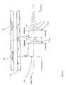
- FIG. 2illustrates a pulse rate controlled flyback converter having primary-only feedback according to one embodiment of the invention.
- FIG. 3illustrates a pulse rate controlled flyback converter having primary-only feedback according to another embodiment of the invention.
- FIGS. 4 and 5are timing diagrams illustrating a primary-only feedback sampling technique according to embodiments of the invention.
- FIGS. 5A and 5Bprovide greater detail of aspects demonstrated in the timing diagrams in FIGS. 4 and 5.
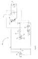
- FIG. 6illustrates an alternative embodiment of a pulse rate controlled flyback converter having primary-only feedback according to yet another embodiment of the invention.
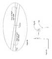
- FIG. 7illustrates a pulse rate controlled forward converter having primary-only feedback according to still another embodiment of the invention.
- FIG. 8illustrates a pulse rate controlled forward converter according to yet another embodiment of the invention.
- FIG. 9illustrates a pulse rate controlled buck converter according to a still further embodiment of the invention.
- FIG. 10is a logical flowchart of a signed digital comparator employed in embodiments of the invention.
- FIG. 11is a logical flowchart of a signed digital early/late detector employed in embodiments of the invention.
- transformer-coupled switching converterssuch as a flyback, forward, fly-forward, push-pull, or bridge-type power converters.
- direct-coupled switching power converterssuch as buck, boost, buck/boost or SEPIC power converters may also benefit from these control methodologies and embodiments.
- pulse rate regulationin itself, controls neither the ON TIME nor the OFF TIME of the power switch in order to regulate the output voltage.
- output regulationmay be accomplished by controlling the rate of independently specified activation pulses presented to the power switch. If the load requires more power, pulses from a pulse generator are allowed to cycle the power switch. Otherwise, pulses from the pulse generator are inhibited from cycling the power switch.
- this decisionis made on a pulse-by-pulse basis. Accordingly, pulse rate regulation resembles a digital (“bang-bang”) servo control method, driving the output voltage toward a reference voltage in discrete steps. As a consequence, in the presence of a fixed load, the output voltage will “limit cycle” about the reference.
- pulse rate control parametersi.e., phase, width, and frequency
- pulse rate regulationpresents the opportunity to realize numerous power stage optimizations obtained at the price of exchanging “ripples” for “limit cycles.”
- the present applicationdiscloses pulse rate regulated isolated power converters with primary-only feedback. Compared to secondary feedback, with its costly opto-isolator circuit and attendant demands on circuit board layout, primary-only feedback offers the potential of cheaper, slimmer power supplies for applications such as consumer electronics.
- FIG. 2illustrates a flyback power converter 100 employing primary-only feedback for regulation purposes.
- the converter 100includes a power stage 35 , which comprises a transformer T 1 having a primary winding 20 and secondary winding 22 , rectifying diode D 1 and filter capacitor C 1 .
- Power stage 35receives an input voltage, V in , produced by a rectifier 92 operating on an AC line input.
- a capacitor 93helps smooth voltage ripple on V in .
- a power pulse generator 60generates a power pulse drive signal 71 that, under the control of a pulse rate controller 70 , cycles switch Q 1 .
- switch Q 1may be a power MOSFET.
- switch Q 1may comprise multiple transistors or other suitable means.
- the pulse rate controller 70determines whether or not a given cycle of drive signal 71 shall cycle switch Q 1 .
- the ON TIME of for each cycle of drive signal 71is of such a duration that, when switch Q 1 is cycled OFF during a single cycle of drive signal 71 , the power stage 35 will transfer a significant pulse of power to the load 24 .
- the controller 70may incorporate pulse optimizing circuitry (“pulse optimizer”) 85 . Based on certain optimizer inputs, the pulse optimizer 85 for determining one or both of the ON and OFF times of a given cycle of the drive signal 71 .
- the flyback power converter 100implements a method of primary-only feedback in the following fashion.
- switch Q 1When switch Q 1 is switched OFF following either a power pulse or sense pulse ON time, the voltage on the secondary winding 22 will be “reflected” back onto the primary winding 20 scaled by the turns ratio, N P /N S , where N P is the number of turns on the primary winding 20 and N S is the number or turns on the secondary winding 22 .
- N Pis the number of turns on the primary winding 20
- N Sis the number or turns on the secondary winding 22 .
- a more suitable signal for sensingmay be provided through the use of an auxiliary winding 105 , as the voltage on this winding 105 is ground referenced.
- V AUXThe reflected voltage, V AUX , on auxiliary winding 105 will be N AUX /N S times the voltage on secondary winding 22 , where N AUX is the number of turns on auxiliary winding 105 , and N S is the turns on secondary winding 22 .
- the relationship between V AUX and V outis given by the expression
- V AUX( V out + ⁇ V ) N AUX /N S (1)
- ⁇ Vis the voltage drop caused by resistive and other losses in the secondary circuit. This voltage drop includes, in particular, losses across rectifying diode D 1 .
- One aspect of the present inventionleverages the notion that by sampling V AUX at precisely determined instants for which the term ⁇ V is small and approximately constant from sample to sample, real-time output voltage feedback can be obtained, where “real-time” output voltage feedback denotes an unfiltered output voltage measurement taken after each power pulse and available to the control logic for the selection of the succeeding drive signal.
- a comparator 151produces an output voltage feedback signal 150 by comparing the V AUX wayeform to a reference voltage, V REF , calibrated to compensate for the average value of ⁇ V at those precisely determined instants when ⁇ V is small and substantially constant from cycle to cycle.
- V REFa reference voltage
- the referencemay be derived from a bandgap voltage reference or other suitable means, such as a compensated zener diode to provide a reliably stable reference voltage.
- Comparator 151 employed to generate feedback signal 150can be more or less sophisticated, depending on the amount of information required to insure acceptable regulation. Perhaps the simplest of comparators is the binary comparator, with or without hysteresis, which indicates V AUX is high or low, relative to V REF . Slightly more sophisticated is the ternary comparator, which indicates high or low or neither, when the magnitude of the difference between V AUX and V REF is less than some fixed voltage.
- a still more sophisticated comparatoris a signed digital comparator, which provides a high or low indication and, in addition, the magnitude of the difference expressed digitally.
- FIG. 10details one embodiment of a signed digital comparator implemented with binary comparators, counters, a digital-to-analog converter, a subtractor, and a minimal amount of control logic, obviating the need for an error amplifier and the sample and hold circuitry characteristic of prior art analog systems.
- the comparatormay indicate “high” by zero units of voltage.
- binary comparators without hysteresisare assumed.
- FIG. 3illustrates a flyback converter 200 similar to converter 100 of FIG. 2, but with a sense pulse generator 61 in addition to a power pulse generator 60 .
- switch Q 1may be cycled by pulses of two different durations.
- the first type of pulseis the previously described “power pulse,” wherein switch Q 1 switches ON for a duration T ON according to drive signal 71 .
- the second type of pulsedenoted herein as a “sense pulse,” is a significantly narrower pulse than a power pulse.
- the sense pulse generator 61To transfer a sense pulse to load 24 , the sense pulse generator 61 generates a sense pulse drive signal 72 to drive switch Q 1 . Because of the reduced ON TIME of switch Q 1 when cycled by a sense pulse from drive signal 72 , power stage 35 transfers an amount of power to load 24 that is significantly less than that transferred by a power pulse.
- the power converter 200is able to use sense pulses from drive signal 72 (as well as power pulses from drive signal 71 ) to stimulate primary-only feedback information for the pulse rate controller 70 .
- sense pulsesfrom drive signal 72 (as well as power pulses from drive signal 71 )
- the number of power pulses per unit of time required to maintain regulationis likely to be small.
- the number of feedback measurements per unit timemay be too small to assure prompt response to step changes in load.
- sense pulse generator 61in addition to power pulse generator 60 ) enables more frequent primary-only feedback information, essential for prompt response to step changes in load, while minimizing power transfer.
- the pulse rate controller 70controls whether power pulse generator 60 , sense pulse generator 61 , or neither, drives switch Q 1 by controlling a multiplexer 95 .
- the multiplexer 95receives as inputs both drive signals 71 and 72 .
- the multiplexer 95can select either drive signal 71 or 72 , or neither, to provide an input to a driver 96 for a given power switch activation cycle.
- Driver 96amplifies the selected signal output by the multiplexer 95 , so that switch Q 1 may be driven accordingly.
- the controller 70may control multiplexer 95 , such that the power pulse rate occurring at the load 24 is substantially constant, regardless of the pattern of drive signal selection.
- Controller 70may or may not keep history; that is, it may or may not remember the results of previous comparisons, depending on complexity of a particular embodiment. If the controller 70 does keep a history, it may reference the history in the process of deciding whether to choose drive signal 71 , drive signal 72 , or neither, to cycle the power switch Q 1 for a given activation cycle.
- the power pulse and sense pulse generators 60 and 61are shown separately in FIG. 3, it will be appreciated that a single pulse generator, comprising, e.g., programmable logic, could be used in place of pulse generators 60 and 61 . Moreover, the precise instants in time when the power switch Q 1 switches ON and OFF as determined by drive signals 71 and 72 may further be controlled by a pulse optimizer 85 , as discussed in greater detail herein.
- the flyback converter 200implements the same method of primary-only feedback as flyback converter 100 in FIG. 2.
- FIG. 4 and FIG. 5are sampling timing diagrams that illustrate the timing of an exemplary power pulse cycle 106 and a sense pulse cycle 107 . Shown are the following waveforms: a) a drive signal 101 to drive the power switch Q 1 , b) an auxiliary voltage waveform 102 , and—in FIG. 4— c) a secondary current I SEC waveform 103 through the rectifying diode D 1 .
- the reflected auxiliary voltage waveform 102swings high when drive signal 101 switches transistor Q 1 from ON to OFF.
- I SEC 103will also jump from a substantially zero current to a relatively high current value, I PEAK , when the drive signal 101 switches transistor Q 1 from ON to OFF.
- I SEC 103will ramp down from this relatively high current value back to a substantially zero current value, assuming discontinuous or critically discontinuous operation.
- T SAMPLEshould occur within the plateau period, as close to the drop off as possible. Hence ⁇ T cannot be made too small, or sampling will be complicated by the collapse of the plateau, preventing a proper sensing of the output voltage.
- the ⁇ V term in above-equation (1)is maintained at a small and approximately constant value regardless of line or load conditions, enabling the potential for precise output regulation.
- An alternative to direct sensing of the secondary currentis the sensing of the transformer reset condition directly or indirectly.
- I SEC 103When I SEC 103 reaches zero the transformer T 1 may be denoted to be in a reset condition. This reset condition occurs when the energy in the primary winding 20 has been completely transferred to the secondary winding 22 . At such a point in time, the voltage across the primary winding 20 will proceed to drop rapidly to zero.
- V AUX across the auxiliary winding 105will also drop rapidly to (and through) zero volts, oscillating around zero until switch ON occurs.
- a zero crossing comparator(not illustrated) could monitor V AUX and detect when it first equals zero following either a power pulse cycle 106 or sense pulse cycle 107 .
- V IN firstthe drain voltage on transistor power switch Q 1 , V DRN , which occurs when V AUX first equals zero.
- T AUXOthe time at which V AUX first equals zero, T AUXO , lags transformer reset by a fixed amount of time and is more easily detected, it provides an attractive means for indirectly measuring transformer reset time.
- the reflected auxiliary voltage waveform 102will have a plateau period during the OFF TIME of either a sense pulse cycle 107 or a power pulse cycle 106 .
- a condition in which reflected auxiliary voltage 102 equals zerowill occur following this plateau period at time 110 .
- the reflected auxiliary voltage 102achieves its first minimum at a time T 3 , which occurs midway between times 110 and 111 .
- This first minimum voltage point, or a subsequent minimummay be advantageously used as the point when the ON period for the next pulse (either a power pulse or a sense pulse) begins.
- the voltage at the drain of transistor Q 1is also a minimum at time T 3 , the switching stresses and losses are minimized.
- the drain voltageis non-zero at time T 3 , it may be denoted as the zero-voltage switching time, because this is as close to zero as the drain voltage will get.
- the pulse optimizer 85accepts a variety of optimizer inputs, including V AUX , and applies these inputs to derive the timing, etc. of power and sense pulses, in order to realize optimizations such as zero-voltage switching.
- an effective and easily-mechanized method for implementing zero-voltage switchingis first, to detect the first and second zero-crossings of V AUX following the turn off of switch Q 1 ; second, to derive the period of resonant oscillation; and third, to adjust both power and sense pulses to turn on at the first zero-crossing of V AUX (T AUXO ), plus ⁇ fraction (1/4) ⁇ of the resonant oscillation period, or T AUXO plus ⁇ fraction (1/4) ⁇ of the resonant oscillation period plus an integral multiple of resonant oscillation periods.
- T SAMPLEcould, for example, be determined from T AUXO by first subtracting 1 ⁇ 4 of the resonant oscillation period to “locate” the transformer reset point, and then subtracting ⁇ T. Having determined the sampling time, T SAMPLE , controller 70 need only evaluate the binary output signal 150 of comparator 151 to determine whether at that instant V AUX is higher or lower than the expected value, V REF .
- V AUXis greater than the reference voltage at the sample time T SAMPLE , the binary output signal 150 will be high. In response to sampling a high binary output signal 150 at T SAMPLE , the controller 70 may drive multiplexer 95 to select the sense pulse drive signal 72 . In this fashion, the following pulse will be a sense pulse so as to transfer as little power to the load 24 as possible to maintain regulation. Alternatively, if V AUX is less than V REF at time T SAMPLE , binary output 150 will be low. In response to sampling a low binary output signal 150 at T SAMPLE , controller 70 may drive multiplexer 95 to select the power pulse drive signal 71 . As a result, the following pulse through power stage 35 will be a power pulse so that the maximum amount of power can be transferred to load 24 to maintain regulation. In this fashion, the output voltage V out across load 24 will be a function of the value of V REF .
- An alternative to sampling the binary output signal 150 at time T SAMPLEis to sample signal 150 periodically to detect the high to low transitions or state changes of said signal, and classify them as “early” or “late” relative to T SAMPLE , where an “early” transition is one that occurs before T SAMPLE , and a “late” transition is one that occurs after T SAMPLE .
- T SAMPLEis, by definition, the expected crossover point of V AUX with V REF , and therefore the expected transition point of binary output signal 150 .
- FIGS. 5A and 5Ba high to low transition of output signal 150 corresponds to V AUX crossing V REF from above.
- FIG. 5Aillustrates the “equivalence” between the condition in which V AUX crosses V REF “early” (relative to T SAMPLE ) and the condition in which binary output signal 150 is “low” at T SAMPLE .
- the condition in which V AUX crosses V REF “late” (or not at all)corresponds to the condition in which binary output signal 150 is “high” at T SAMPLE .
- an early/late detectorcan be more or less sophisticated, depending on the amount of information required to insure acceptable regulation.
- a binary detectorwhich indicates early or late, relative to T SAMPLE .
- the ternary detectorwhich indicates early, late, or neither, when the magnitude of the earliness or lateness is less than some fixed interval of time.
- a still more sophisticated early/late detectoris a signed digital detector, which provides an early or late indication and, in addition, the magnitude of the earliness or lateness expressed digitally.
- FIG. 11illustrates one embodiment of a signed digital early/late detector implemented with binary comparators, counters, a subtractor, and a minimal amount of control logic, obviating the need for an error amplifier and the sample and hold circuitry characteristic of prior art analog systems.
- a transition of binary output signal 150 that occurs at precisely T SAMPLEwill be classified (by the detector) as “early” by zero units of time.
- Sense pulsesplay an important role in the output voltage regulation scheme. Since output voltage feedback is based on the reflected voltage across the transformer T 1 , either a sense or power pulse must be sent in order for a sample of the output voltage to be obtained. Because the amount of energy transferred to the load is significantly lower than that of power pulses, sense pulses allow for a greater number of samples of the output voltage to be taken without adversely impacting output regulation. The more frequently the output is sampled, the better the regulation and the better the response to step changes in load.
- the pulse rate controller 70would be expected to command a continuous train of sense pulses 107 for transmission through power stage 35 .
- the energy content of sense pulsesis small compared to that of power pulses, in the absence of load 24 , it is possible that the output voltage V out will still rise to a level above the desired regulation set point.
- controller 70may be desirable in embodiments of the controller 70 to incorporate a “skip mode” of operation, wherein controller 70 inhibits pulsing of the switch Q 1 for short periods by causing multiplexer 95 to select neither the power pulse drive signal 71 nor the sense pulse drive signal 72 , i.e., would instead select GND.
- Controller 70may detect that a low-load or no-load condition is true by measuring the frequency of sense pulses transferred through the power stage 35 . Alternatively, it may utilize the magnitude information provided by a signed digital comparator or signed digital early/late detector to detect the disappearance (or reappearance) of the load. Once in skip mode, the logic in controller 70 intersperses sense pulses with no pulses, to maintain good regulation with an appropriate level of response to step changes in load without creating excessive audible noise. The process of interspersing sense pulses could be pseudo-random, e.g., employing a linear feedback shift register.
- the pulse optimizer 85may be implemented as software on a programmable processor, or may be formed by a single component.
- the flyback converter 300 illustrated in FIG. 6has the functions of pulse generation and pulse optimization formed by a state machine 170 fed by one or more binary comparators.
- the state machine 170may contain a single pulse generator that may be commanded to produce either a sense pulse drive signal or a power pulse drive signal. In such an embodiment, there is no need for a multiplexer. Pulse timing may be supplied by optimizer logic, with the ON TIME and OFF TIME supplied by pulse rate controller logic. Should a skip mode be desired, the state machine 170 could simply command its pulse generator to not generate a sense pulse drive signal.
- FIG. 7is a forward converter 180 in accordance with an embodiment of the invention.
- the pulse optimizer 85 , power pulse generator 60 , sense pulse generator 61 , comparator 151 , controller 70 , multiplexer 95 , and driver 96serve the respective functions in converter 180 as described previously with respect to flyback converter 200 of FIG. 3.
- two or more of the pulse optimizer 85 , power pulse generator 60 , sense pulse generator 61 , multiplexer 95 , and pulse rate controller 70 of converter 180may be formed by a single component, such as a state machine, or as software on a programmable processor.
- the output voltage of forward converter 180is not reflected across the power transformer T 1 , as it is in a flyback converter.
- the reflected voltage of the outputmay be sensed via a primary-side auxiliary winding 105 magnetically coupled to an output inductor L 1 located at the output of the rectifier diode D 1 .
- the reflected voltage across the auxiliary winding 105(V AUX ) provides an output voltage feedback signal for input to comparator 151 .
- the sampling of V AUXpreferably occurs at times when the current through the rectifying diode D 1 is small and constant, sample to sample, as described above in detail.
- FIG. 8illustrates a pulse rate regulated boost converter 280 .
- the pulse optimizer 85 , power pulse generator 60 , sense pulse generator 61 , comparator 151 , controller 70 , multiplexer 95 , and driver 96serve the same respective functions in converter 280 as in the transformer-coupled flyback and forward converters of FIGS. 3 and 7.
- two or more of the pulse optimizer 85 , power pulse generator 60 , sense pulse generator 61 , multiplexer 95 , and pulse rate controller 70 of converter 280may be formed by a single component, e.g., a state machine, or as software on a programmable processor. While the logic of the pulse optimizer 85 and pulse rate controller 70 in converter 280 may be different from that employed in flyback and forward converters, the above-described primary-only feedback method may nevertheless still be implemented, as shown in FIG. 8.
- the voltage across the switch Q 1 during its OFF timeprovides a suitable approximation of the output voltage when sampled at those precisely determined instants for which the current through the rectifier diode D 1 is small and constant, sample to sample, as described above in detail.
- FIG. 9illustrates a pulse rate regulated buck converter.
- the pulse optimizer 85 , power pulse generator 60 , sense pulse generator 61 , comparator 151 , controller 70 , multiplexer 95 , and driver 96serve the same respective functions in converter 380 as in the transformer-coupled converters 200 (FIG. 3) and 180 (FIG. 7).
- two or more of these componentsmay be implemented as a single component, e.g., as a state machine, or as software on a programmable processor.
- the differential voltage across the output inductor L 1 during the OFF time of the switch Q 1provides a suitable approximation to the output voltage when sampled at those precisely determined instants for which the current through the rectifier diode D 1 is small and constant, sample to sample, as described in detail above.
Landscapes
- Engineering & Computer Science (AREA)
- Power Engineering (AREA)
- Dc-Dc Converters (AREA)
Abstract
Description
- This application is a continuation-in-part of U.S. application Ser. No. 09/970,849, filed Oct. 3, 2001, which is a continuation-in-part of U.S. application Ser. No. 09/279,949, filed Oct. 4, 2000, now U.S. Pat. No. 6,304,473, which is a continuation-in-part of U.S. application Ser. No. 09/585,928, filed Jun. 2, 2000, now U.S. Patent No. 6,275,018, each of which is fully incorporated herein by reference. This application also claims priority to provisional application Serial No. 60/335,723, filed Nov. 29, 2001, which is fully incorporated herein by reference.[0001]
- The invention pertains generally to the field of power conversion and more particularly to methods for controlling power converters.[0002]
- Switching power converters offer both compactness and efficiency in a number of different topologies that can be placed in two main categories: isolated (or transformer-coupled) and non-isolated (or direct-coupled). In non-isolated switching power converters, such as a buck (reducing voltage) or boost (increasing voltage) converter, the power output is directly coupled to the power input through the power switch element. In contrast, in isolated power converters, such as flyback or forward converters, the power output is isolated from the power input through a transformer, with the power switch element located on the primary (input) side of the transformer.[0003]
- In either type of converter, typical analog control systems use pulse width modulation (PWM), pulse frequency modulation (PFM), or a combination thereof to control the duty cycle of the power switch within the converter.[0004]
- Consider, for example, the[0005]
flyback converter 10 of FIG. 1. Theconverter 10 includes a power switch Q1 (typically a field effect transistor (FET)) coupled to an input voltage, Vin, via aprimary winding 20 of a power transformer T1. A rectifying diode D1 and filter capacitor C1 are coupled to asecondary winding 22 of the transformer T1. Theconverter 10 includes apulse modulating controller 25 that outputs adrive signal 61 to turn ON the power switch Q1 in order to control an output voltage, Vout, across aload 24. A primary/secondary isolation circuit 30 provides an output voltage feedback signal that approximates the output voltage acrossload 24. An errorvoltage sense circuit 31 generates an error voltage from inputs that include a reference voltage, VREF, as well as the output voltage feedback signal from primary/secondary isolation circuit 30. This error voltage is used by thecontroller 25 for regulating the ON time of the power switch Q1. - Obtaining the output voltage feedback signal from the secondary side of the converter, as shown in FIG. 1, offers the potential of accurate regulation performance, but necessarily increases the complexity and cost of the control system. If a primary-side feedback system were used instead, the output voltage feedback signal would be obtained from the primary side of power transformer T[0006]1, reducing cost and complexity of the control system, but introducing difficulties with regulation accuracy.
- In particular, a reflected voltage across the[0007]
primary winding 20 is proportional to the output voltage across theload 24 minus a voltage drop produced by resistive and other losses in the secondary circuit, including losses across the rectifying diode D1. These losses will vary, depending upon the current drawn by the load and other factors. Hence, measuring the output voltage through the reflected flyback voltage is problematic, as parasitic losses act as a corrupting signal that cannot be removed by filtering. As such, prior art primary-side feedback systems, such as that disclosed in U.S. Pat. No. 5,438,499, which depends upon the reflected voltage, are challenged to provide good voltage regulation. - Accordingly, there is a need in the art for power converters having primary-only feedback that achieves regulation performance traditionally obtainable with secondary feedback, while preserving the intended simplicity and cost benefits of primary-only feedback.[0008]
- In accordance with one aspect of the invention, methods for regulating voltage at an output of a switching power converter having a power switch using primary-only feedback are provided. In one implementation, the method includes sensing an output voltage feedback signal, comparing the sensed feedback signal to a reference at a determined time during a cycling of the switch, and regulating the output voltage at a load by controlling whether a cycle of one or more drive signals produced by pulse generation circuitry should cycle a switch, in response to an output of the comparison. In exemplary implementations, the comparison is accomplished by one of binary comparison logic, ternary comparison logic and signed digital comparison logic.[0009]
- The methods may be used in conjunctions with both transformer-coupled and direct-coupled converters. By way of example, in one implementation, the converter is transformer-coupled having its output coupled through a rectifying element, with the feedback signal originating from the primary side of the converter. In one embodiment of this implementation, the determined time is when the feedback signal corresponds to the output voltage at the load plus a small, substantially constant voltage drop measured from cycle to cycle of the switch. In another embodiment of this implementation, the determined time is when current flowing through a secondary rectifying element is small and substantially constant from cycle to cycle of the switch.[0010]
- In one implementation, the converter is a flyback topology, the feedback signal is a reflected flyback voltage signal, and the determined time is a fixed backward offset time from the transformer flux reset point.[0011]
- In another implementation, the converter is a forward converter, the output voltage feedback signal is a reflected voltage across an auxiliary winding coupled to the output inductor, and the determined time is at a fixed backward offset time from a point of output inductor flux reset.[0012]
- In yet another implementation, the converter is a direct-coupled boost converter, the output voltage feedback signal corresponds to a voltage across the switch during its OFF time, and the determined time is at an instant when current through a rectifying element is small and substantially constant from cycle to cycle of the switch.[0013]
- In still another implementation, the converter is a direct-coupled buck converter, the output voltage feedback signal corresponds to a differential voltage across an output inductor during the off time of the high-side switch, and the determined time is at an instant when current through a rectifying element is small and substantially constant from cycle to cycle.[0014]
- In selected implementations, the pulse generation circuitry includes a first pulse generator for producing a first drive signal for cycling the switch ON and OFF, wherein if the switch is cycled ON and OFF according to a cycle of the first drive signal, a power pulse is transferred from the source to the load, and a second pulse generator for producing a second drive signal for cycling the switch ON and OFF, wherein if the switch is cycled ON and OFF according to a cycle of the second drive signal, a sense pulse is transferred from the source to the load, the power transferred to the load by a sense pulse being substantially less than the power transferred to the load by a power pulse, the converter including a controller which enables cycling of the switch by a cycle of a power pulse, sense pulse, or neither, in response to the comparison. In some embodiments, the controller make take into account comparisons from one or more previous switch cycles in determining whether to enable cycling of the switch by a cycle of a power pulse, sense pulse, or neither, in response to a present comparison.[0015]
- Other and further aspects and embodiments of the invention will become apparent upon review of the accompanying figures and the following detailed description.[0016]
- The various aspects and features of the invention will be better understood by examining the figures, in which similar elements in different embodiments are given the same reference numbers for ease in illustration, and in which:[0017]
- FIG. 1 is a block diagram illustrating a flyback converter with a pulse modulating controller.[0018]
- FIG. 2 illustrates a pulse rate controlled flyback converter having primary-only feedback according to one embodiment of the invention.[0019]
- FIG. 3 illustrates a pulse rate controlled flyback converter having primary-only feedback according to another embodiment of the invention.[0020]
- FIGS. 4 and 5 are timing diagrams illustrating a primary-only feedback sampling technique according to embodiments of the invention.[0021]
- FIGS. 5A and 5B provide greater detail of aspects demonstrated in the timing diagrams in FIGS. 4 and 5.[0022]
- FIG. 6 illustrates an alternative embodiment of a pulse rate controlled flyback converter having primary-only feedback according to yet another embodiment of the invention.[0023]
- FIG. 7 illustrates a pulse rate controlled forward converter having primary-only feedback according to still another embodiment of the invention.[0024]
- FIG. 8 illustrates a pulse rate controlled forward converter according to yet another embodiment of the invention.[0025]
- FIG. 9 illustrates a pulse rate controlled buck converter according to a still further embodiment of the invention.[0026]
- FIG. 10 is a logical flowchart of a signed digital comparator employed in embodiments of the invention.[0027]
- FIG. 11 is a logical flowchart of a signed digital early/late detector employed in embodiments of the invention.[0028]
- It will be apparent to those skilled in the art that the power converter control system methodologies and embodiments disclosed and described herein may be applied to transformer-coupled switching converters, such as a flyback, forward, fly-forward, push-pull, or bridge-type power converters. In addition, as will be explained herein, direct-coupled switching power converters such as buck, boost, buck/boost or SEPIC power converters may also benefit from these control methodologies and embodiments.[0029]
- The above-incorporated U.S. Pat. No. 6,275,018 discloses and describes various embodiments of a “pulse rate” (also referred to as “pulse train”) method of power converter regulation. Notably, pulse rate regulation, in itself, controls neither the ON TIME nor the OFF TIME of the power switch in order to regulate the output voltage. Instead, output regulation may be accomplished by controlling the rate of independently specified activation pulses presented to the power switch. If the load requires more power, pulses from a pulse generator are allowed to cycle the power switch. Otherwise, pulses from the pulse generator are inhibited from cycling the power switch.[0030]
- In one embodiment, this decision is made on a pulse-by-pulse basis. Accordingly, pulse rate regulation resembles a digital (“bang-bang”) servo control method, driving the output voltage toward a reference voltage in discrete steps. As a consequence, in the presence of a fixed load, the output voltage will “limit cycle” about the reference.[0031]
- In contrast, prior art analog control methods (e.g., PWM and PFM) endeavor to construct pulses that will drive the output voltage onto the reference. In this case, owing to practical limits on the width and frequency of pulses, in the presence of a fixed load, the output voltage will “ripple” about the reference. Because pulse rate control parameters (i.e., phase, width, and frequency) are specified independently of regulation, pulse rate regulation presents the opportunity to realize numerous power stage optimizations obtained at the price of exchanging “ripples” for “limit cycles.”[0032]
- The present application discloses pulse rate regulated isolated power converters with primary-only feedback. Compared to secondary feedback, with its costly opto-isolator circuit and attendant demands on circuit board layout, primary-only feedback offers the potential of cheaper, slimmer power supplies for applications such as consumer electronics.[0033]
- FIG. 2 illustrates a[0034]
flyback power converter 100 employing primary-only feedback for regulation purposes. Theconverter 100 includes apower stage 35, which comprises a transformer T1 having a primary winding20 and secondary winding22, rectifying diode D1 and filter capacitorC1. Power stage 35 receives an input voltage, Vin, produced by arectifier 92 operating on an AC line input. Acapacitor 93 helps smooth voltage ripple on Vin. Apower pulse generator 60 generates a powerpulse drive signal 71 that, under the control of apulse rate controller 70, cycles switch Q1. As illustrated, switch Q1 may be a power MOSFET. Alternatively, switch Q1 may comprise multiple transistors or other suitable means. - Instead of controlling the ON TIME and OFF TIME of switch Q[0035]1, based on a feedback signal corresponding to the output voltage, the
pulse rate controller 70 determines whether or not a given cycle ofdrive signal 71 shall cycle switch Q1. The ON TIME of for each cycle ofdrive signal 71 is of such a duration that, when switch Q1 is cycled OFF during a single cycle ofdrive signal 71, thepower stage 35 will transfer a significant pulse of power to theload 24. As will be described in greater detail herein, thecontroller 70 may incorporate pulse optimizing circuitry (“pulse optimizer”)85. Based on certain optimizer inputs, thepulse optimizer 85 for determining one or both of the ON and OFF times of a given cycle of thedrive signal 71. - The[0036]
flyback power converter 100 implements a method of primary-only feedback in the following fashion. When switch Q1 is switched OFF following either a power pulse or sense pulse ON time, the voltage on the secondary winding22 will be “reflected” back onto the primary winding20 scaled by the turns ratio, NP/NS, where NPis the number of turns on the primary winding20 and NSis the number or turns on the secondary winding22. Although the voltage across the primary winding20 could be sensed to perform primary-only feedback control, a more suitable signal for sensing may be provided through the use of an auxiliary winding105, as the voltage on this winding105 is ground referenced. The reflected voltage, VAUX, on auxiliary winding105 will be NAUX/NStimes the voltage on secondary winding22, where NAUXis the number of turns on auxiliary winding105, and NSis the turns on secondary winding22. The relationship between VAUXand Voutis given by the expression - VAUX=(Vout+ΔV)NAUX/NS (1)
- where ΔV is the voltage drop caused by resistive and other losses in the secondary circuit. This voltage drop includes, in particular, losses across rectifying diode D[0037]1.
- One aspect of the present invention leverages the notion that by sampling V[0038]AUXat precisely determined instants for which the term ΔV is small and approximately constant from sample to sample, real-time output voltage feedback can be obtained, where “real-time” output voltage feedback denotes an unfiltered output voltage measurement taken after each power pulse and available to the control logic for the selection of the succeeding drive signal.
- A[0039]
comparator 151 produces an outputvoltage feedback signal 150 by comparing the VAUXwayeform to a reference voltage, VREF, calibrated to compensate for the average value of ΔV at those precisely determined instants when ΔV is small and substantially constant from cycle to cycle. For example, the reference may be derived from a bandgap voltage reference or other suitable means, such as a compensated zener diode to provide a reliably stable reference voltage. By this calibration of VREF, those precisely determined instants define not only the instants at which accurate, real-time output voltage feedback is available, but also the instants at which VAUXand VREFare expected to crossover, resulting in a transition or state change in the outputvoltage feedback signal 150. - [0040]
Comparator 151 employed to generate feedback signal150 can be more or less sophisticated, depending on the amount of information required to insure acceptable regulation. Perhaps the simplest of comparators is the binary comparator, with or without hysteresis, which indicates VAUXis high or low, relative to VREF. Slightly more sophisticated is the ternary comparator, which indicates high or low or neither, when the magnitude of the difference between VAUXand VREFis less than some fixed voltage. - A still more sophisticated comparator is a signed digital comparator, which provides a high or low indication and, in addition, the magnitude of the difference expressed digitally. FIG. 10 details one embodiment of a signed digital comparator implemented with binary comparators, counters, a digital-to-analog converter, a subtractor, and a minimal amount of control logic, obviating the need for an error amplifier and the sample and hold circuitry characteristic of prior art analog systems. In the example of FIG. 10, under the condition in which V[0041]AUXequals VREFat precisely TSAMPLE, the comparator may indicate “high” by zero units of voltage. In the embodiments discussed herein, binary comparators without hysteresis are assumed.
- FIG. 3 illustrates a[0042]
flyback converter 200 similar toconverter 100 of FIG. 2, but with asense pulse generator 61 in addition to apower pulse generator 60. In this case, switch Q1 may be cycled by pulses of two different durations. The first type of pulse is the previously described “power pulse,” wherein switch Q1 switches ON for a duration TONaccording to drivesignal 71. The second type of pulse, denoted herein as a “sense pulse,” is a significantly narrower pulse than a power pulse. To transfer a sense pulse to load24, thesense pulse generator 61 generates a sensepulse drive signal 72 to drive switch Q1. Because of the reduced ON TIME of switch Q1 when cycled by a sense pulse fromdrive signal 72,power stage 35 transfers an amount of power to load24 that is significantly less than that transferred by a power pulse. - As is explained further herein, the[0043]
power converter 200 is able to use sense pulses from drive signal72 (as well as power pulses from drive signal71) to stimulate primary-only feedback information for thepulse rate controller 70. For example, in low load situations, the number of power pulses per unit of time required to maintain regulation is likely to be small. As a consequence, the number of feedback measurements per unit time may be too small to assure prompt response to step changes in load. The incorporation of sense pulse generator61 (in addition to power pulse generator60) enables more frequent primary-only feedback information, essential for prompt response to step changes in load, while minimizing power transfer. - To regulate output voltage, V[0044]out, the
pulse rate controller 70 controls whetherpower pulse generator 60,sense pulse generator 61, or neither, drives switch Q1 by controlling amultiplexer 95. In particular, themultiplexer 95 receives as inputs both drivesignals multiplexer 95 can select either drivesignal driver 96 for a given power switch activation cycle.Driver 96 amplifies the selected signal output by themultiplexer 95, so that switch Q1 may be driven accordingly. In this manner, thecontroller 70 may controlmultiplexer 95, such that the power pulse rate occurring at theload 24 is substantially constant, regardless of the pattern of drive signal selection. - [0045]
Controller 70 may or may not keep history; that is, it may or may not remember the results of previous comparisons, depending on complexity of a particular embodiment. If thecontroller 70 does keep a history, it may reference the history in the process of deciding whether to choosedrive signal 71,drive signal 72, or neither, to cycle the power switch Q1 for a given activation cycle. - Although the power pulse and[0046]
sense pulse generators pulse generators drive signals pulse optimizer 85, as discussed in greater detail herein. - The[0047]
flyback converter 200 implements the same method of primary-only feedback asflyback converter 100 in FIG. 2. - FIG. 4 and FIG. 5 are sampling timing diagrams that illustrate the timing of an exemplary[0048]
power pulse cycle 106 and asense pulse cycle 107. Shown are the following waveforms: a) adrive signal 101 to drive the power switch Q1, b) anauxiliary voltage waveform 102, and—in FIG. 4— c) a secondary current ISECwaveform103 through the rectifying diode D1. - For both a[0049]
power pulse cycle 106 and asense pulse cycle 107, the reflectedauxiliary voltage waveform 102 swings high whendrive signal 101 switches transistor Q1 from ON to OFF. Similarly, ISEC103 will also jump from a substantially zero current to a relatively high current value, IPEAK, when thedrive signal 101 switches transistor Q1 from ON to OFF. Duringdrive signal 101 OFF TIME, ISEC103 will ramp down from this relatively high current value back to a substantially zero current value, assuming discontinuous or critically discontinuous operation. Sampling the binary output signal150 (FIG. 3) at times when ISEC=K Amps, where K=a small and constant value, will insure that the ΔV term in the above-equation (1) remains small and approximately constant from sample to sample. - To implement the foregoing, with reference also to FIG. 3, it suffices to sample[0050]
binary output signal 150 at time TSAMPLE, where TSAMPLEoccurs at a fixed backward offset ΔT from the zero points of the secondary current ISEC(for sense pulses and power pulses). This is because the current ISECdecays at the same rate for sense pulses as for power pulses. Note that the reflectedvoltage waveform 102 forms a “plateau” period of relatively constant voltage while ISEC103 ramps down to zero current. As ISEC103 reaches zero current, this plateau voltage drops off steeply. Thus, to get a good reading of the output voltage onload 24 by way of VAUX, TSAMPLEshould occur within the plateau period, as close to the drop off as possible. Hence ΔT cannot be made too small, or sampling will be complicated by the collapse of the plateau, preventing a proper sensing of the output voltage. - By sampling ΔT time ahead of the zero points of the secondary current (for sense pulses and power pulses), the ΔV term in above-equation (1) is maintained at a small and approximately constant value regardless of line or load conditions, enabling the potential for precise output regulation.[0051]
- An alternative to direct sensing of the secondary current (an appropriate methodology for single-output converters) is the sensing of the transformer reset condition directly or indirectly. When I[0052]SEC103 reaches zero the transformer T1 may be denoted to be in a reset condition. This reset condition occurs when the energy in the primary winding20 has been completely transferred to the secondary winding22. At such a point in time, the voltage across the primary winding20 will proceed to drop rapidly to zero.
- Referring to FIG. 5, it can be seen that at the transformer reset point, the voltage V[0053]AUXacross the auxiliary winding105 will also drop rapidly to (and through) zero volts, oscillating around zero until switch ON occurs. Thus, to detect a reset condition, a zero crossing comparator (not illustrated) could monitor VAUXand detect when it first equals zero following either a
power pulse cycle 106 orsense pulse cycle 107. - Alternatively, another comparator (not illustrated) could detect when V[0054]INfirst equals the drain voltage on transistor power switch Q1, VDRN, which occurs when VAUXfirst equals zero. Because the time at which VAUXfirst equals zero, TAUXO, lags transformer reset by a fixed amount of time and is more easily detected, it provides an attractive means for indirectly measuring transformer reset time.
- After the transformer has reached reset, there is still energy stored in the drain-source capacitance of transistor Q[0055]1, regardless of whether transistor Q1 has been cycled according to drive signal71 (to produce a power pulse) or drive signal72 (to produce a sense pulse). Assuming that transistor Q1 is not immediately cycled ON at this point, this energy then resonantly oscillates with the magnetizing inductance of the primary winding22 at a resonant frequency determined by the capacitance and inductance values. The frequency (or period) of this resonance is substantially the same regardless of whether a sense pulse or power pulse has been sent through
power stage 35. The resonant oscillation of VAUXis illustrated in FIG. 4 and FIG. 5. - As seen in FIG. 5, the reflected[0056]
auxiliary voltage waveform 102 will have a plateau period during the OFF TIME of either asense pulse cycle 107 or apower pulse cycle 106. A condition in which reflectedauxiliary voltage 102 equals zero will occur following this plateau period attime 110. By measuring the time difference between the first zero crossing point ofV AUX110 following the turn OFF of switch Q1, and the second zero crossing point ofV AUX111, it is possible to empirically derive the period of resonant oscillation following flux reset. This empirically derived value of the resonant oscillation period is useful in fixing the setback from TAUXOto the transformer reset point (see below). - The reflected[0057]
auxiliary voltage 102 achieves its first minimum at a time T3, which occurs midway betweentimes - With reference again to the[0058]
converter 200 of FIG. 3, as disclosed and discussed in the above-incorporated U.S. application Ser. No. 09/970,849, U.S. Pat. No. 6,304,473, and U.S. provisional application Serial No. 60/335,723, thepulse optimizer 85 accepts a variety of optimizer inputs, including VAUX, and applies these inputs to derive the timing, etc. of power and sense pulses, in order to realize optimizations such as zero-voltage switching. As the foregoing paragraphs suggest, an effective and easily-mechanized method for implementing zero-voltage switching is first, to detect the first and second zero-crossings of VAUXfollowing the turn off of switch Q1; second, to derive the period of resonant oscillation; and third, to adjust both power and sense pulses to turn on at the first zero-crossing of VAUX(TAUXO), plus {fraction (1/4)} of the resonant oscillation period, or TAUXOplus {fraction (1/4)} of the resonant oscillation period plus an integral multiple of resonant oscillation periods. - Where the foregoing method is used to implement zero-voltage switching, the time T[0059]AUXOand the period of resonant oscillation generated by the
pulse optimizer 85 can both be made available topulse rate controller 70 for use in the determination of TSAMPLE. TSAMPLEcould, for example, be determined from TAUXOby first subtracting ¼ of the resonant oscillation period to “locate” the transformer reset point, and then subtracting ΔT. Having determined the sampling time, TSAMPLE,controller 70 need only evaluate thebinary output signal 150 ofcomparator 151 to determine whether at that instant VAUXis higher or lower than the expected value, VREF. - If V[0060]AUXis greater than the reference voltage at the sample time TSAMPLE, the
binary output signal 150 will be high. In response to sampling a highbinary output signal 150 at TSAMPLE, thecontroller 70 may drivemultiplexer 95 to select the sensepulse drive signal 72. In this fashion, the following pulse will be a sense pulse so as to transfer as little power to theload 24 as possible to maintain regulation. Alternatively, if VAUXis less than VREFat time TSAMPLE,binary output 150 will be low. In response to sampling a lowbinary output signal 150 at TSAMPLE,controller 70 may drivemultiplexer 95 to select the powerpulse drive signal 71. As a result, the following pulse throughpower stage 35 will be a power pulse so that the maximum amount of power can be transferred to load24 to maintain regulation. In this fashion, the output voltage Voutacrossload 24 will be a function of the value of VREF. - An alternative to sampling the[0061]
binary output signal 150 at time TSAMPLEis to sample signal150 periodically to detect the high to low transitions or state changes of said signal, and classify them as “early” or “late” relative to TSAMPLE, where an “early” transition is one that occurs before TSAMPLE, and a “late” transition is one that occurs after TSAMPLE. This follows from the fact that TSAMPLEis, by definition, the expected crossover point of VAUXwith VREF, and therefore the expected transition point ofbinary output signal 150. - As illustrated in FIGS. 5A and 5B, a high to low transition of[0062]
output signal 150 corresponds to VAUXcrossing VREFfrom above. In particular, FIG. 5A illustrates the “equivalence” between the condition in which VAUXcrosses VREF“early” (relative to TSAMPLE) and the condition in whichbinary output signal 150 is “low” at TSAMPLE. Similarly, the condition in which VAUXcrosses VREF“late” (or not at all) corresponds to the condition in whichbinary output signal 150 is “high” at TSAMPLE. - Notably, an early/late detector can be more or less sophisticated, depending on the amount of information required to insure acceptable regulation. Perhaps the simplest of early/late detectors is a binary detector, which indicates early or late, relative to T[0063]SAMPLE. Slightly more sophisticated is the ternary detector, which indicates early, late, or neither, when the magnitude of the earliness or lateness is less than some fixed interval of time. A still more sophisticated early/late detector is a signed digital detector, which provides an early or late indication and, in addition, the magnitude of the earliness or lateness expressed digitally.
- FIG. 11 illustrates one embodiment of a signed digital early/late detector implemented with binary comparators, counters, a subtractor, and a minimal amount of control logic, obviating the need for an error amplifier and the sample and hold circuitry characteristic of prior art analog systems. In the embodiment of FIG. 11, a transition of[0064]
binary output signal 150 that occurs at precisely TSAMPLEwill be classified (by the detector) as “early” by zero units of time. - Sense pulses play an important role in the output voltage regulation scheme. Since output voltage feedback is based on the reflected voltage across the transformer T[0065]1, either a sense or power pulse must be sent in order for a sample of the output voltage to be obtained. Because the amount of energy transferred to the load is significantly lower than that of power pulses, sense pulses allow for a greater number of samples of the output voltage to be taken without adversely impacting output regulation. The more frequently the output is sampled, the better the regulation and the better the response to step changes in load.
- When the[0066]
load 24 becomes very light or is removed from theflyback converter 200 of FIG. 3, thepulse rate controller 70 would be expected to command a continuous train ofsense pulses 107 for transmission throughpower stage 35. Although the energy content of sense pulses is small compared to that of power pulses, in the absence ofload 24, it is possible that the output voltage Voutwill still rise to a level above the desired regulation set point. As such, in order to maintain good regulation under low-load or no-load conditions, it may be desirable in embodiments of thecontroller 70 to incorporate a “skip mode” of operation, whereincontroller 70 inhibits pulsing of the switch Q1 for short periods by causingmultiplexer 95 to select neither the powerpulse drive signal 71 nor the sensepulse drive signal 72, i.e., would instead select GND. - [0067]
Controller 70 may detect that a low-load or no-load condition is true by measuring the frequency of sense pulses transferred through thepower stage 35. Alternatively, it may utilize the magnitude information provided by a signed digital comparator or signed digital early/late detector to detect the disappearance (or reappearance) of the load. Once in skip mode, the logic incontroller 70 intersperses sense pulses with no pulses, to maintain good regulation with an appropriate level of response to step changes in load without creating excessive audible noise. The process of interspersing sense pulses could be pseudo-random, e.g., employing a linear feedback shift register. - Although shown separately in FIGS. 2 and 3, it will be appreciated that two or more of the[0068]
pulse optimizer 85,power pulse generator 60, sense pulse generator61 (if applicable), multiplexer95 (if applicable), andpulse rate controller 70 may be implemented as software on a programmable processor, or may be formed by a single component. For example, theflyback converter 300 illustrated in FIG. 6, has the functions of pulse generation and pulse optimization formed by astate machine 170 fed by one or more binary comparators. Thestate machine 170 may contain a single pulse generator that may be commanded to produce either a sense pulse drive signal or a power pulse drive signal. In such an embodiment, there is no need for a multiplexer. Pulse timing may be supplied by optimizer logic, with the ON TIME and OFF TIME supplied by pulse rate controller logic. Should a skip mode be desired, thestate machine 170 could simply command its pulse generator to not generate a sense pulse drive signal. - Although the above discussion has been with respect to flyback converters, it will be appreciated that primary-only feedback methods of the present invention may be implemented in other isolated power converters such as a forward converter. By way of illustration, FIG. 7 is a[0069]
forward converter 180 in accordance with an embodiment of the invention. Thepulse optimizer 85,power pulse generator 60,sense pulse generator 61,comparator 151,controller 70,multiplexer 95, anddriver 96 serve the respective functions inconverter 180 as described previously with respect toflyback converter 200 of FIG. 3. It will similarly be appreciated that in alternate embodiments two or more of thepulse optimizer 85,power pulse generator 60,sense pulse generator 61,multiplexer 95, andpulse rate controller 70 ofconverter 180 may be formed by a single component, such as a state machine, or as software on a programmable processor. - Notably, the output voltage of[0070]
forward converter 180 is not reflected across the power transformer T1, as it is in a flyback converter. Instead, the reflected voltage of the output may be sensed via a primary-side auxiliary winding105 magnetically coupled to an output inductor L1 located at the output of the rectifier diode D1. In this manner, the reflected voltage across the auxiliary winding105 (VAUX) provides an output voltage feedback signal for input tocomparator 151. The sampling of VAUXpreferably occurs at times when the current through the rectifying diode D1 is small and constant, sample to sample, as described above in detail. - The primary-only feedback method disclosed and described herein may also be extended to direct-coupled switching power converters. FIG. 8 illustrates a pulse rate regulated[0071]
boost converter 280. Thepulse optimizer 85,power pulse generator 60,sense pulse generator 61,comparator 151,controller 70,multiplexer 95, anddriver 96 serve the same respective functions inconverter 280 as in the transformer-coupled flyback and forward converters of FIGS. 3 and 7. Similarly, it will be appreciated that in alternate embodiments two or more of thepulse optimizer 85,power pulse generator 60,sense pulse generator 61,multiplexer 95, andpulse rate controller 70 ofconverter 280 may be formed by a single component, e.g., a state machine, or as software on a programmable processor. While the logic of thepulse optimizer 85 andpulse rate controller 70 inconverter 280 may be different from that employed in flyback and forward converters, the above-described primary-only feedback method may nevertheless still be implemented, as shown in FIG. 8. Inconverter 280, the voltage across the switch Q1 during its OFF time provides a suitable approximation of the output voltage when sampled at those precisely determined instants for which the current through the rectifier diode D1 is small and constant, sample to sample, as described above in detail. - FIG. 9 illustrates a pulse rate regulated buck converter. The[0072]
pulse optimizer 85,power pulse generator 60,sense pulse generator 61,comparator 151,controller 70,multiplexer 95, anddriver 96 serve the same respective functions inconverter 380 as in the transformer-coupled converters200 (FIG. 3) and180 (FIG. 7). Similarly, in alternate embodiments two or more of these components may be implemented as a single component, e.g., as a state machine, or as software on a programmable processor. Those skilled in the art will appreciate that while the logic of therespective pulse optimizer 85 andpulse rate controller 70 inconverter 380 may be different from that employed in flyback or forward converters, a primary-only feedback method for optimized regulation ofconverter 380 may nevertheless be implemented, as shown in FIG. 9. - In particular, in[0073]
converter 380 the differential voltage across the output inductor L1 during the OFF time of the switch Q1 provides a suitable approximation to the output voltage when sampled at those precisely determined instants for which the current through the rectifier diode D1 is small and constant, sample to sample, as described in detail above. - Specific embodiments illustrating various aspects and features of the invention have been shown by way of example in the drawings and are herein described in detail. However, it is to be understood that the invention is not to be limited to the particular embodiments or methods shown or described, but to the contrary, the invention broadly cover all modifications, equivalents, and alternatives encompassed by the scope of the appended claims and their equivalents.[0074]
Claims (28)
Priority Applications (1)
| Application Number | Priority Date | Filing Date | Title |
|---|---|---|---|
| US10/306,780US6894911B2 (en) | 2000-06-02 | 2002-11-27 | Method of driving a power converter by using a power pulse and a sense pulse |
Applications Claiming Priority (5)
| Application Number | Priority Date | Filing Date | Title |
|---|---|---|---|
| US09/585,928US6275018B1 (en) | 2000-06-02 | 2000-06-02 | Switching power converter with gated oscillator controller |
| US09/679,949US6304473B1 (en) | 2000-06-02 | 2000-10-04 | Operating a power converter at optimal efficiency |
| US09/970,849US20020057080A1 (en) | 2000-06-02 | 2001-10-03 | Optimized digital regulation of switching power supply |
| US33572301P | 2001-11-29 | 2001-11-29 | |
| US10/306,780US6894911B2 (en) | 2000-06-02 | 2002-11-27 | Method of driving a power converter by using a power pulse and a sense pulse |
Related Parent Applications (1)
| Application Number | Title | Priority Date | Filing Date |
|---|---|---|---|
| US09/970,849Continuation-In-PartUS20020057080A1 (en) | 2000-06-02 | 2001-10-03 | Optimized digital regulation of switching power supply |
Publications (2)
| Publication Number | Publication Date |
|---|---|
| US20030128018A1true US20030128018A1 (en) | 2003-07-10 |
| US6894911B2 US6894911B2 (en) | 2005-05-17 |
Family
ID=27502523
Family Applications (1)
| Application Number | Title | Priority Date | Filing Date |
|---|---|---|---|
| US10/306,780Expired - LifetimeUS6894911B2 (en) | 2000-06-02 | 2002-11-27 | Method of driving a power converter by using a power pulse and a sense pulse |
Country Status (1)
| Country | Link |
|---|---|
| US (1) | US6894911B2 (en) |
Cited By (13)
| Publication number | Priority date | Publication date | Assignee | Title |
|---|---|---|---|---|
| WO2006067522A2 (en) | 2004-12-21 | 2006-06-29 | Cambridge Semiconductor Limited | Power supply control system |
| US20060174939A1 (en)* | 2004-12-29 | 2006-08-10 | Isg Technologies Llc | Efficiency booster circuit and technique for maximizing power point tracking |
| US20060199620A1 (en)* | 2005-02-24 | 2006-09-07 | Firefly Power Technologies, Inc. | Method, apparatus and system for power transmission |
| US20070149162A1 (en)* | 2005-02-24 | 2007-06-28 | Powercast, Llc | Pulse transmission method |
| US20080246447A1 (en)* | 2007-04-06 | 2008-10-09 | Power Integrations, Inc. | Method and apparatus for integrated cable drop compensation of a power converter |
| US20080278131A1 (en)* | 2007-05-09 | 2008-11-13 | Park Young-Bae | Switching mode power supply and driving method thereof |
| US20090262561A1 (en)* | 2005-09-15 | 2009-10-22 | Power Integrations, Inc. | Method and apparatus to improve regulation of a power supply |
| US20100039099A1 (en)* | 2008-08-12 | 2010-02-18 | Hynix Semiconductor, Inc. | Power noise detecting device and power noise control device using the same |
| US20110316524A1 (en)* | 2010-06-23 | 2011-12-29 | Hyundai Motor Company | Apparatus for diagnosing dc-dc converter and method thereof |
| US20120268971A1 (en)* | 2011-03-16 | 2012-10-25 | Bonkee Kim | Power supply for controlling current |
| KR101215074B1 (en) | 2011-03-16 | 2012-12-24 | 주식회사 하이딥 | Power supply for controlling current |
| US20140268955A1 (en)* | 2013-03-15 | 2014-09-18 | Flextronics Ap, Llc | No load detection |
| US9601982B1 (en) | 2013-08-27 | 2017-03-21 | Flextronics Ap, Llc | Switchable auxiliary supply circuit |
Families Citing this family (97)
| Publication number | Priority date | Publication date | Assignee | Title |
|---|---|---|---|---|
| US6876181B1 (en)* | 1998-02-27 | 2005-04-05 | Power Integrations, Inc. | Off-line converter with digital control |
| US6525514B1 (en)* | 2000-08-08 | 2003-02-25 | Power Integrations, Inc. | Method and apparatus for reducing audio noise in a switching regulator |
| US7839022B2 (en) | 2004-07-13 | 2010-11-23 | Tigo Energy, Inc. | Device for distributed maximum power tracking for solar arrays |
| US7142140B2 (en) | 2004-07-27 | 2006-11-28 | Silicon Laboratories Inc. | Auto scanning ADC for DPWM |
| US7417877B2 (en)* | 2004-07-27 | 2008-08-26 | Silicon Laboratories Inc. | Digital power supply with programmable soft start |
| US7233504B2 (en) | 2005-08-26 | 2007-06-19 | Power Integration, Inc. | Method and apparatus for digital control of a switching regulator |
| US8721203B2 (en)* | 2005-10-06 | 2014-05-13 | Zih Corp. | Memory system and method for consumables of a printer |
| US11881814B2 (en) | 2005-12-05 | 2024-01-23 | Solaredge Technologies Ltd. | Testing of a photovoltaic panel |
| US10693415B2 (en) | 2007-12-05 | 2020-06-23 | Solaredge Technologies Ltd. | Testing of a photovoltaic panel |
| CN100517899C (en)* | 2006-04-30 | 2009-07-22 | 艾默生网络能源系统有限公司 | Protection Circuits for Power Converters |
| US8751053B2 (en)* | 2006-10-19 | 2014-06-10 | Tigo Energy, Inc. | Method and system to provide a distributed local energy production system with high-voltage DC bus |
| KR100894565B1 (en)* | 2006-11-01 | 2009-04-24 | 박찬웅 | Circuit for output voltage error detect and feedback in SMPS |
| US9112379B2 (en) | 2006-12-06 | 2015-08-18 | Solaredge Technologies Ltd. | Pairing of components in a direct current distributed power generation system |
| US11296650B2 (en) | 2006-12-06 | 2022-04-05 | Solaredge Technologies Ltd. | System and method for protection during inverter shutdown in distributed power installations |
| US8473250B2 (en) | 2006-12-06 | 2013-06-25 | Solaredge, Ltd. | Monitoring of distributed power harvesting systems using DC power sources |
| US11888387B2 (en) | 2006-12-06 | 2024-01-30 | Solaredge Technologies Ltd. | Safety mechanisms, wake up and shutdown methods in distributed power installations |
| US9088178B2 (en) | 2006-12-06 | 2015-07-21 | Solaredge Technologies Ltd | Distributed power harvesting systems using DC power sources |
| US8816535B2 (en) | 2007-10-10 | 2014-08-26 | Solaredge Technologies, Ltd. | System and method for protection during inverter shutdown in distributed power installations |
| US11855231B2 (en) | 2006-12-06 | 2023-12-26 | Solaredge Technologies Ltd. | Distributed power harvesting systems using DC power sources |
| US8319483B2 (en) | 2007-08-06 | 2012-11-27 | Solaredge Technologies Ltd. | Digital average input current control in power converter |
| US8013472B2 (en) | 2006-12-06 | 2011-09-06 | Solaredge, Ltd. | Method for distributed power harvesting using DC power sources |
| US11309832B2 (en) | 2006-12-06 | 2022-04-19 | Solaredge Technologies Ltd. | Distributed power harvesting systems using DC power sources |
| US9130401B2 (en) | 2006-12-06 | 2015-09-08 | Solaredge Technologies Ltd. | Distributed power harvesting systems using DC power sources |
| US8319471B2 (en) | 2006-12-06 | 2012-11-27 | Solaredge, Ltd. | Battery power delivery module |
| US8618692B2 (en) | 2007-12-04 | 2013-12-31 | Solaredge Technologies Ltd. | Distributed power system using direct current power sources |
| US8947194B2 (en) | 2009-05-26 | 2015-02-03 | Solaredge Technologies Ltd. | Theft detection and prevention in a power generation system |
| US11735910B2 (en) | 2006-12-06 | 2023-08-22 | Solaredge Technologies Ltd. | Distributed power system using direct current power sources |
| US8384243B2 (en) | 2007-12-04 | 2013-02-26 | Solaredge Technologies Ltd. | Distributed power harvesting systems using DC power sources |
| US11687112B2 (en) | 2006-12-06 | 2023-06-27 | Solaredge Technologies Ltd. | Distributed power harvesting systems using DC power sources |
| US8963369B2 (en) | 2007-12-04 | 2015-02-24 | Solaredge Technologies Ltd. | Distributed power harvesting systems using DC power sources |
| US12316274B2 (en) | 2006-12-06 | 2025-05-27 | Solaredge Technologies Ltd. | Pairing of components in a direct current distributed power generation system |
| US7480159B2 (en)* | 2007-04-19 | 2009-01-20 | Leadtrend Technology Corp. | Switching-mode power converter and pulse-width-modulation control circuit with primary-side feedback control |
| US8933321B2 (en)* | 2009-02-05 | 2015-01-13 | Tigo Energy, Inc. | Systems and methods for an enhanced watchdog in solar module installations |
| US7884278B2 (en)* | 2007-11-02 | 2011-02-08 | Tigo Energy, Inc. | Apparatuses and methods to reduce safety risks associated with photovoltaic systems |
| US11228278B2 (en) | 2007-11-02 | 2022-01-18 | Tigo Energy, Inc. | System and method for enhanced watch dog in solar panel installations |
| US7602080B1 (en) | 2008-11-26 | 2009-10-13 | Tigo Energy, Inc. | Systems and methods to balance solar panels in a multi-panel system |
| US8823218B2 (en) | 2007-11-02 | 2014-09-02 | Tigo Energy, Inc. | System and method for enhanced watch dog in solar panel installations |
| US9218013B2 (en)* | 2007-11-14 | 2015-12-22 | Tigo Energy, Inc. | Method and system for connecting solar cells or slices in a panel system |
| WO2009072076A2 (en) | 2007-12-05 | 2009-06-11 | Solaredge Technologies Ltd. | Current sensing on a mosfet |
| US11264947B2 (en) | 2007-12-05 | 2022-03-01 | Solaredge Technologies Ltd. | Testing of a photovoltaic panel |
| US7898112B2 (en)* | 2007-12-06 | 2011-03-01 | Tigo Energy, Inc. | Apparatuses and methods to connect power sources to an electric power system |
| US20090234692A1 (en)* | 2008-03-13 | 2009-09-17 | Tigo Energy, Inc. | Method and System for Configuring Solar Energy Systems |
| US8111052B2 (en) | 2008-03-24 | 2012-02-07 | Solaredge Technologies Ltd. | Zero voltage switching |
| EP2294669B8 (en) | 2008-05-05 | 2016-12-07 | Solaredge Technologies Ltd. | Direct current power combiner |
| US8098055B2 (en)* | 2008-08-01 | 2012-01-17 | Tigo Energy, Inc. | Step-up converter systems and methods |
| US8325059B2 (en)* | 2008-11-12 | 2012-12-04 | Tigo Energy, Inc. | Method and system for cost-effective power line communications for sensor data collection |
| US8653689B2 (en)* | 2008-11-12 | 2014-02-18 | Tigo Energy, Inc. | Method and system for current-mode power line communications |
| US8860241B2 (en)* | 2008-11-26 | 2014-10-14 | Tigo Energy, Inc. | Systems and methods for using a power converter for transmission of data over the power feed |
| CN101447737B (en)* | 2008-12-25 | 2012-04-18 | 杭州电子科技大学 | Constant power output direct current transforming circuit |
| US9401439B2 (en) | 2009-03-25 | 2016-07-26 | Tigo Energy, Inc. | Enhanced systems and methods for using a power converter for balancing modules in single-string and multi-string configurations |
| US8039730B2 (en)* | 2009-06-18 | 2011-10-18 | Tigo Energy, Inc. | System and method for prevention of open loop damage during or immediately after manufacturing |
| US8954203B2 (en)* | 2009-06-24 | 2015-02-10 | Tigo Energy, Inc. | Systems and methods for distributed power factor correction and phase balancing |
| US8405349B2 (en)* | 2009-06-25 | 2013-03-26 | Tigo Energy, Inc. | Enhanced battery storage and recovery energy systems |
| US8102074B2 (en)* | 2009-07-30 | 2012-01-24 | Tigo Energy, Inc. | Systems and method for limiting maximum voltage in solar photovoltaic power generation systems |
| US9312697B2 (en) | 2009-07-30 | 2016-04-12 | Tigo Energy, Inc. | System and method for addressing solar energy production capacity loss due to field buildup between cells and glass and frame assembly |
| US8314375B2 (en) | 2009-08-21 | 2012-11-20 | Tigo Energy, Inc. | System and method for local string management unit |
| US20110048502A1 (en)* | 2009-08-28 | 2011-03-03 | Tigo Energy, Inc. | Systems and Methods of Photovoltaic Cogeneration |
| US9143036B2 (en) | 2009-09-02 | 2015-09-22 | Tigo Energy, Inc. | Systems and methods for enhanced efficiency auxiliary power supply module |
| US9324885B2 (en) | 2009-10-02 | 2016-04-26 | Tigo Energy, Inc. | Systems and methods to provide enhanced diode bypass paths |
| US12418177B2 (en) | 2009-10-24 | 2025-09-16 | Solaredge Technologies Ltd. | Distributed power system using direct current power sources |
| US8773236B2 (en)* | 2009-12-29 | 2014-07-08 | Tigo Energy, Inc. | Systems and methods for a communication protocol between a local controller and a master controller |
| US8854193B2 (en) | 2009-12-29 | 2014-10-07 | Tigo Energy, Inc. | Systems and methods for remote or local shut-off of a photovoltaic system |
| US8213192B2 (en)* | 2009-12-30 | 2012-07-03 | Silicon Laboratories Inc. | Primary side sensing for isolated fly-back converters |
| US8271599B2 (en)* | 2010-01-08 | 2012-09-18 | Tigo Energy, Inc. | Systems and methods for an identification protocol between a local controller and a master controller in a photovoltaic power generation system |
| US9425783B2 (en) | 2010-03-15 | 2016-08-23 | Tigo Energy, Inc. | Systems and methods to provide enhanced diode bypass paths |
| US8922061B2 (en)* | 2010-03-22 | 2014-12-30 | Tigo Energy, Inc. | Systems and methods for detecting and correcting a suboptimal operation of one or more inverters in a multi-inverter system |
| US9312399B2 (en) | 2010-04-02 | 2016-04-12 | Tigo Energy, Inc. | Systems and methods for mapping the connectivity topology of local management units in photovoltaic arrays |
| US9007210B2 (en) | 2010-04-22 | 2015-04-14 | Tigo Energy, Inc. | Enhanced system and method for theft prevention in a solar power array during nonoperative periods |
| US8853886B2 (en) | 2010-06-09 | 2014-10-07 | Tigo Energy, Inc. | System for use of static inverters in variable energy generation environments |
| US10673222B2 (en) | 2010-11-09 | 2020-06-02 | Solaredge Technologies Ltd. | Arc detection and prevention in a power generation system |
| US10230310B2 (en) | 2016-04-05 | 2019-03-12 | Solaredge Technologies Ltd | Safety switch for photovoltaic systems |
| GB2485527B (en) | 2010-11-09 | 2012-12-19 | Solaredge Technologies Ltd | Arc detection and prevention in a power generation system |
| US10673229B2 (en) | 2010-11-09 | 2020-06-02 | Solaredge Technologies Ltd. | Arc detection and prevention in a power generation system |
| GB2486408A (en) | 2010-12-09 | 2012-06-20 | Solaredge Technologies Ltd | Disconnection of a string carrying direct current |
| GB2483317B (en) | 2011-01-12 | 2012-08-22 | Solaredge Technologies Ltd | Serially connected inverters |
| US9043039B2 (en) | 2011-02-24 | 2015-05-26 | Tigo Energy, Inc. | System and method for arc detection and intervention in solar energy systems |
| US8841916B2 (en) | 2011-02-28 | 2014-09-23 | Tigo Energy, Inc. | System and method for flash bypass |
| US9368965B2 (en) | 2011-07-28 | 2016-06-14 | Tigo Energy, Inc. | Enhanced system and method for string-balancing |
| US9142965B2 (en) | 2011-07-28 | 2015-09-22 | Tigo Energy, Inc. | Systems and methods to combine strings of solar panels |
| US9431825B2 (en) | 2011-07-28 | 2016-08-30 | Tigo Energy, Inc. | Systems and methods to reduce the number and cost of management units of distributed power generators |
| US8982591B2 (en) | 2011-10-18 | 2015-03-17 | Tigo Energy, Inc. | System and method for exchangeable capacitor modules for high power inverters and converters |
| GB2498365A (en) | 2012-01-11 | 2013-07-17 | Solaredge Technologies Ltd | Photovoltaic module |
| GB2498791A (en) | 2012-01-30 | 2013-07-31 | Solaredge Technologies Ltd | Photovoltaic panel circuitry |
| US9853565B2 (en) | 2012-01-30 | 2017-12-26 | Solaredge Technologies Ltd. | Maximized power in a photovoltaic distributed power system |
| GB2498790A (en) | 2012-01-30 | 2013-07-31 | Solaredge Technologies Ltd | Maximising power in a photovoltaic distributed power system |
| GB2499991A (en) | 2012-03-05 | 2013-09-11 | Solaredge Technologies Ltd | DC link circuit for photovoltaic array |
| US10115841B2 (en) | 2012-06-04 | 2018-10-30 | Solaredge Technologies Ltd. | Integrated photovoltaic panel circuitry |
| US9548619B2 (en) | 2013-03-14 | 2017-01-17 | Solaredge Technologies Ltd. | Method and apparatus for storing and depleting energy |
| US9941813B2 (en) | 2013-03-14 | 2018-04-10 | Solaredge Technologies Ltd. | High frequency multi-level inverter |
| EP3506370B1 (en) | 2013-03-15 | 2023-12-20 | Solaredge Technologies Ltd. | Bypass mechanism |
| US9318974B2 (en) | 2014-03-26 | 2016-04-19 | Solaredge Technologies Ltd. | Multi-level inverter with flying capacitor topology |
| US10218307B2 (en) | 2014-12-02 | 2019-02-26 | Tigo Energy, Inc. | Solar panel junction boxes having integrated function modules |
| US9806614B2 (en)* | 2015-12-17 | 2017-10-31 | Texas Instruments Incorporated | Low power zero inductor current detection circuit |
| DE102016100758A1 (en)* | 2016-01-18 | 2017-07-20 | Sma Solar Technology Ag | Separating device for a photovoltaic string, solar system and operating method for a solar system with photovoltaic string |
| US12057807B2 (en) | 2016-04-05 | 2024-08-06 | Solaredge Technologies Ltd. | Chain of power devices |
| US11018623B2 (en) | 2016-04-05 | 2021-05-25 | Solaredge Technologies Ltd. | Safety switch for photovoltaic systems |
| US11177663B2 (en) | 2016-04-05 | 2021-11-16 | Solaredge Technologies Ltd. | Chain of power devices |
Citations (35)
| Publication number | Priority date | Publication date | Assignee | Title |
|---|---|---|---|---|
| US4589051A (en)* | 1983-12-22 | 1986-05-13 | General Electric Company | Second breakdown protection circuit for X-ray generator inverter |
| US4597026A (en)* | 1983-12-22 | 1986-06-24 | General Electric Company | Inverter variable dead time for X-ray generator |
| US4819144A (en)* | 1987-07-31 | 1989-04-04 | Toko, Inc. | Switching power supply circuit with stored charge removal switch |
| US4975820A (en)* | 1989-09-01 | 1990-12-04 | National Semiconductor Corporation | Adaptive compensating ramp generator for current-mode DC/DC converters |
| US5028861A (en)* | 1989-05-24 | 1991-07-02 | Motorola, Inc. | Strobed DC-DC converter with current regulation |
| US5146398A (en)* | 1991-08-20 | 1992-09-08 | Led Corporation N.V. | Power factor correction device provided with a frequency and amplitude modulated boost converter |
| US5189599A (en)* | 1991-08-14 | 1993-02-23 | Zenith Electronics Corporation | High voltage regulator for an integrated horizontal sweep system |
| US5285366A (en)* | 1992-09-24 | 1994-02-08 | Northern Telecom Limited | Current limit circuit in current mode power supplies |
| US5313381A (en)* | 1992-09-01 | 1994-05-17 | Power Integrations, Inc. | Three-terminal switched mode power supply integrated circuit |
| US5479090A (en)* | 1993-11-24 | 1995-12-26 | Raytheon Company | Power converter having optimal dynamic operation |
| US5565761A (en)* | 1994-09-02 | 1996-10-15 | Micro Linear Corp | Synchronous switching cascade connected offline PFC-PWM combination power converter controller |
| US5570276A (en)* | 1993-11-15 | 1996-10-29 | Optimun Power Conversion, Inc. | Switching converter with open-loop input voltage regulation on primary side and closed-loop load regulation on secondary side |
| US5629841A (en)* | 1993-02-13 | 1997-05-13 | Attwood; Brian E. | Low power dc-dc converter |
| US5680034A (en)* | 1995-09-22 | 1997-10-21 | Toko, Inc. | PWM controller for resonant converters |
| US5747977A (en)* | 1995-03-30 | 1998-05-05 | Micro Linear Corporation | Switching regulator having low power mode responsive to load power consumption |
| US5764039A (en)* | 1995-11-15 | 1998-06-09 | Samsung Electronics Co., Ltd. | Power factor correction circuit having indirect input voltage sensing |
| US5804950A (en)* | 1996-06-20 | 1998-09-08 | Micro Linear Corporation | Input current modulation for power factor correction |
| US5815380A (en)* | 1993-11-16 | 1998-09-29 | Optimum Power Conversion, Inc. | Switching converter with open-loop primary side regulation |
| US5822200A (en)* | 1997-04-21 | 1998-10-13 | Nt International, Inc. | Low level, high efficiency DC/DC converter |
| US5828558A (en)* | 1998-02-11 | 1998-10-27 | Powerdsine, Ltd. | PWN controller use with open loop flyback type DC to AC converter |
| US5831418A (en)* | 1996-12-03 | 1998-11-03 | Fujitsu Ltd. | Step-up/down DC-to-DC converter |
| US5841643A (en)* | 1997-10-01 | 1998-11-24 | Linear Technology Corporation | Method and apparatus for isolated flyback regulator control and load compensation |
| US5862045A (en)* | 1998-04-16 | 1999-01-19 | Motorola, Inc. | Switched mode power supply controller and method |
| US5886885A (en)* | 1995-12-15 | 1999-03-23 | Hitachi, Ltd. | DC power unit and information processing apparatus with the DC power unit |
| US5886586A (en)* | 1996-09-06 | 1999-03-23 | The Regents Of The University Of California | General constant frequency pulse-width modulators |
| US5892355A (en)* | 1997-03-21 | 1999-04-06 | Pansier; Frans | Current and voltage-sensing |
| US5932938A (en)* | 1997-10-02 | 1999-08-03 | Fujitsu Limited | Switching power supply unit |
| US5949229A (en)* | 1996-08-28 | 1999-09-07 | Samsung Electronics, Co., Ltd. | Power factor correction circuit having an error signal multiplied by a current signal |
| US6049471A (en)* | 1998-02-11 | 2000-04-11 | Powerdsine Ltd. | Controller for pulse width modulation circuit using AC sine wave from DC input signal |
| US6087816A (en)* | 1999-06-29 | 2000-07-11 | Maxim Integrated Products, Inc. | Step-up/step-down switching regulators and pulse width modulation control therefor |
| US6115274A (en)* | 1999-06-01 | 2000-09-05 | Lucent Technologies Inc. | Frequency modulation controller for single-switch, polyphase, DCM boost converter and method of operation thereof |
| US6181583B1 (en)* | 1999-01-19 | 2001-01-30 | Matsushita Electric Industrial Co., Ltd. | Power supply device and air conditioner using the same |
| US6208528B1 (en)* | 1998-05-11 | 2001-03-27 | Nidec America Corporation | Power supply with surface mounted magnetic components having sheet material windings |
| US6275018B1 (en)* | 2000-06-02 | 2001-08-14 | Iwatt | Switching power converter with gated oscillator controller |
| US6304473B1 (en)* | 2000-06-02 | 2001-10-16 | Iwatt | Operating a power converter at optimal efficiency |
Family Cites Families (10)
| Publication number | Priority date | Publication date | Assignee | Title |
|---|---|---|---|---|
| DE4122945A1 (en)* | 1991-07-11 | 1993-01-14 | Philips Patentverwaltung | MICROPROCESSOR CONTROLLED DC CONVERTER |
| US5909106A (en) | 1994-11-06 | 1999-06-01 | U.S. Philips Corporation | Control signal for a voltage generator for an LCD screen control circuit |
| EP0922323B1 (en) | 1997-03-27 | 2002-10-30 | Koninklijke Philips Electronics N.V. | Digitally controlled switched-mode voltage converter |
| US6020729A (en)* | 1997-12-16 | 2000-02-01 | Volterra Semiconductor Corporation | Discrete-time sampling of data for use in switching regulators |
| JP2000116027A (en) | 1998-03-10 | 2000-04-21 | Fiderikkusu:Kk | Power supply device |
| US6307356B1 (en)* | 1998-06-18 | 2001-10-23 | Linear Technology Corporation | Voltage mode feedback burst mode circuit |
| US6246220B1 (en)* | 1999-09-01 | 2001-06-12 | Intersil Corporation | Synchronous-rectified DC to DC converter with improved current sensing |
| EP1124315B1 (en) | 2000-02-11 | 2007-01-03 | Semiconductor Components Industries, LLC | Switched mode power supply with programmable pulse skipping mode |
| US6396250B1 (en)* | 2000-08-31 | 2002-05-28 | Texas Instruments Incorporated | Control method to reduce body diode conduction and reverse recovery losses |
| US6597159B2 (en)* | 2001-08-15 | 2003-07-22 | System General Corp. | Pulse width modulation controller having frequency modulation for power converter |
- 2002
- 2002-11-27USUS10/306,780patent/US6894911B2/ennot_activeExpired - Lifetime
Patent Citations (36)
| Publication number | Priority date | Publication date | Assignee | Title |
|---|---|---|---|---|
| US4597026A (en)* | 1983-12-22 | 1986-06-24 | General Electric Company | Inverter variable dead time for X-ray generator |
| US4589051A (en)* | 1983-12-22 | 1986-05-13 | General Electric Company | Second breakdown protection circuit for X-ray generator inverter |
| US4819144A (en)* | 1987-07-31 | 1989-04-04 | Toko, Inc. | Switching power supply circuit with stored charge removal switch |
| US5028861A (en)* | 1989-05-24 | 1991-07-02 | Motorola, Inc. | Strobed DC-DC converter with current regulation |
| US4975820A (en)* | 1989-09-01 | 1990-12-04 | National Semiconductor Corporation | Adaptive compensating ramp generator for current-mode DC/DC converters |
| US5189599A (en)* | 1991-08-14 | 1993-02-23 | Zenith Electronics Corporation | High voltage regulator for an integrated horizontal sweep system |
| US5276604A (en)* | 1991-08-14 | 1994-01-04 | Zenith Electronics Corporation | High voltage regulator for an integrated horizontal sweep system |
| US5146398A (en)* | 1991-08-20 | 1992-09-08 | Led Corporation N.V. | Power factor correction device provided with a frequency and amplitude modulated boost converter |
| US5313381A (en)* | 1992-09-01 | 1994-05-17 | Power Integrations, Inc. | Three-terminal switched mode power supply integrated circuit |
| US5285366A (en)* | 1992-09-24 | 1994-02-08 | Northern Telecom Limited | Current limit circuit in current mode power supplies |
| US5629841A (en)* | 1993-02-13 | 1997-05-13 | Attwood; Brian E. | Low power dc-dc converter |
| US5570276A (en)* | 1993-11-15 | 1996-10-29 | Optimun Power Conversion, Inc. | Switching converter with open-loop input voltage regulation on primary side and closed-loop load regulation on secondary side |
| US5815380A (en)* | 1993-11-16 | 1998-09-29 | Optimum Power Conversion, Inc. | Switching converter with open-loop primary side regulation |
| US5479090A (en)* | 1993-11-24 | 1995-12-26 | Raytheon Company | Power converter having optimal dynamic operation |
| US5565761A (en)* | 1994-09-02 | 1996-10-15 | Micro Linear Corp | Synchronous switching cascade connected offline PFC-PWM combination power converter controller |
| US5747977A (en)* | 1995-03-30 | 1998-05-05 | Micro Linear Corporation | Switching regulator having low power mode responsive to load power consumption |
| US5680034A (en)* | 1995-09-22 | 1997-10-21 | Toko, Inc. | PWM controller for resonant converters |
| US5764039A (en)* | 1995-11-15 | 1998-06-09 | Samsung Electronics Co., Ltd. | Power factor correction circuit having indirect input voltage sensing |
| US5886885A (en)* | 1995-12-15 | 1999-03-23 | Hitachi, Ltd. | DC power unit and information processing apparatus with the DC power unit |
| US5804950A (en)* | 1996-06-20 | 1998-09-08 | Micro Linear Corporation | Input current modulation for power factor correction |
| US5949229A (en)* | 1996-08-28 | 1999-09-07 | Samsung Electronics, Co., Ltd. | Power factor correction circuit having an error signal multiplied by a current signal |
| US5886586A (en)* | 1996-09-06 | 1999-03-23 | The Regents Of The University Of California | General constant frequency pulse-width modulators |
| US5831418A (en)* | 1996-12-03 | 1998-11-03 | Fujitsu Ltd. | Step-up/down DC-to-DC converter |
| US5892355A (en)* | 1997-03-21 | 1999-04-06 | Pansier; Frans | Current and voltage-sensing |
| US5822200A (en)* | 1997-04-21 | 1998-10-13 | Nt International, Inc. | Low level, high efficiency DC/DC converter |
| US5841643A (en)* | 1997-10-01 | 1998-11-24 | Linear Technology Corporation | Method and apparatus for isolated flyback regulator control and load compensation |
| US5932938A (en)* | 1997-10-02 | 1999-08-03 | Fujitsu Limited | Switching power supply unit |
| US5828558A (en)* | 1998-02-11 | 1998-10-27 | Powerdsine, Ltd. | PWN controller use with open loop flyback type DC to AC converter |
| US6049471A (en)* | 1998-02-11 | 2000-04-11 | Powerdsine Ltd. | Controller for pulse width modulation circuit using AC sine wave from DC input signal |
| US5862045A (en)* | 1998-04-16 | 1999-01-19 | Motorola, Inc. | Switched mode power supply controller and method |
| US6208528B1 (en)* | 1998-05-11 | 2001-03-27 | Nidec America Corporation | Power supply with surface mounted magnetic components having sheet material windings |
| US6181583B1 (en)* | 1999-01-19 | 2001-01-30 | Matsushita Electric Industrial Co., Ltd. | Power supply device and air conditioner using the same |
| US6115274A (en)* | 1999-06-01 | 2000-09-05 | Lucent Technologies Inc. | Frequency modulation controller for single-switch, polyphase, DCM boost converter and method of operation thereof |
| US6087816A (en)* | 1999-06-29 | 2000-07-11 | Maxim Integrated Products, Inc. | Step-up/step-down switching regulators and pulse width modulation control therefor |
| US6275018B1 (en)* | 2000-06-02 | 2001-08-14 | Iwatt | Switching power converter with gated oscillator controller |
| US6304473B1 (en)* | 2000-06-02 | 2001-10-16 | Iwatt | Operating a power converter at optimal efficiency |
Cited By (24)
| Publication number | Priority date | Publication date | Assignee | Title |
|---|---|---|---|---|
| WO2006067522A2 (en) | 2004-12-21 | 2006-06-29 | Cambridge Semiconductor Limited | Power supply control system |
| US20060174939A1 (en)* | 2004-12-29 | 2006-08-10 | Isg Technologies Llc | Efficiency booster circuit and technique for maximizing power point tracking |
| US20060199620A1 (en)* | 2005-02-24 | 2006-09-07 | Firefly Power Technologies, Inc. | Method, apparatus and system for power transmission |
| US20070149162A1 (en)* | 2005-02-24 | 2007-06-28 | Powercast, Llc | Pulse transmission method |
| EP1764901A3 (en)* | 2005-09-15 | 2009-12-30 | Power Integrations, Inc. | Method and apparatus to improve regulation of a power supply with a compensation signal responsive to the switching signal |
| US7760523B2 (en) | 2005-09-15 | 2010-07-20 | Power Integrations, Inc. | Method and apparatus to improve regulation of a power supply |
| US20090262561A1 (en)* | 2005-09-15 | 2009-10-22 | Power Integrations, Inc. | Method and apparatus to improve regulation of a power supply |
| US8035254B2 (en) | 2007-04-06 | 2011-10-11 | Power Integrations, Inc. | Method and apparatus for integrated cable drop compensation of a power converter |
| US9293996B2 (en) | 2007-04-06 | 2016-03-22 | Power Integrations, Inc. | Method and apparatus for integrated cable drop compensation of a power converter |
| US9065346B2 (en) | 2007-04-06 | 2015-06-23 | Power Integrations, Inc. | Method and apparatus for integrated cable drop compensation of a power converter |
| US20080246447A1 (en)* | 2007-04-06 | 2008-10-09 | Power Integrations, Inc. | Method and apparatus for integrated cable drop compensation of a power converter |
| US7710746B2 (en) | 2007-05-09 | 2010-05-04 | Fairchild Korea Semiconductor, Ltd. | Switching mode power supply and driving method thereof |
| US20080278131A1 (en)* | 2007-05-09 | 2008-11-13 | Park Young-Bae | Switching mode power supply and driving method thereof |
| US7952364B2 (en)* | 2008-08-12 | 2011-05-31 | Hynix Semiconductor Inc. | Power noise detecting device and power noise control device using the same |
| US20100039099A1 (en)* | 2008-08-12 | 2010-02-18 | Hynix Semiconductor, Inc. | Power noise detecting device and power noise control device using the same |
| US20110316524A1 (en)* | 2010-06-23 | 2011-12-29 | Hyundai Motor Company | Apparatus for diagnosing dc-dc converter and method thereof |
| US8587291B2 (en)* | 2010-06-23 | 2013-11-19 | Hyundai Motor Company | Apparatus for diagnosing DC-DC converter and method thereof |
| US20120268971A1 (en)* | 2011-03-16 | 2012-10-25 | Bonkee Kim | Power supply for controlling current |
| US8988904B2 (en)* | 2011-03-16 | 2015-03-24 | Hideep Inc. | Power supply with integrator for controlling current |
| KR101215074B1 (en) | 2011-03-16 | 2012-12-24 | 주식회사 하이딥 | Power supply for controlling current |
| US20140268955A1 (en)* | 2013-03-15 | 2014-09-18 | Flextronics Ap, Llc | No load detection |
| US9711990B2 (en) | 2013-03-15 | 2017-07-18 | Flextronics Ap, Llc | No load detection and slew rate compensation |
| US9843212B2 (en)* | 2013-03-15 | 2017-12-12 | Flextronics Ap, Llc | No load detection |
| US9601982B1 (en) | 2013-08-27 | 2017-03-21 | Flextronics Ap, Llc | Switchable auxiliary supply circuit |
Also Published As
| Publication number | Publication date |
|---|---|
| US6894911B2 (en) | 2005-05-17 |
Similar Documents
| Publication | Publication Date | Title |
|---|---|---|
| US6894911B2 (en) | Method of driving a power converter by using a power pulse and a sense pulse | |
| US6882552B2 (en) | Power converter driven by power pulse and sense pulse | |
| US6900995B2 (en) | PWM power converter controlled by transistion detection of a comparator error signal | |
| WO2004051834A1 (en) | Digital regulation of power converters using primary-only feedback | |
| JP3494223B2 (en) | DC-DC converter | |
| US6304473B1 (en) | Operating a power converter at optimal efficiency | |
| CN102341762B (en) | Power control for transition between multiple modulation modes | |
| US10284096B2 (en) | Current converter with control on the primary winding side and compensation of the propagation delay | |
| US7499295B2 (en) | Switch mode power supply controllers | |
| US8970198B2 (en) | Switch-mode power supply having reduced audible noise | |
| US7443700B2 (en) | On-time control for constant current mode in a flyback power supply | |
| CN102801325B (en) | System and method for regulating switching frequency and peak current of power converter | |
| EP0483852B1 (en) | Power source circuit | |
| US7551460B2 (en) | Switch mode power supply controllers | |
| JP3116338B2 (en) | Switching power supply | |
| US20020057080A1 (en) | Optimized digital regulation of switching power supply | |
| US20020067626A1 (en) | Dc-to-dc converter | |
| US20210384814A1 (en) | Method for driving an electronic switch in a power converter circuit and control circuit | |
| US7248487B1 (en) | Switch mode power supply controllers | |
| EP2101400A2 (en) | Method and apparatus for AC to DC power conversion with reduced harmonic current | |
| US20070216396A1 (en) | Switch mode power supply sensing systems | |
| US6977830B2 (en) | Power supply apparatus | |
| JPH11289764A (en) | Secondary post regulator for power converter | |
| JPH10323028A (en) | DC-DC converter | |
| WO2007135454A1 (en) | Switch mode power supply controllers |
Legal Events
| Date | Code | Title | Description |
|---|---|---|---|
| AS | Assignment | Owner name:IWATT, INC., CALIFORNIA Free format text:ASSIGNMENT OF ASSIGNORS INTEREST;ASSIGNORS:TELEFUS, MARK D.;MUEGGE, MARK R.;GEBER, CHARLES R.;AND OTHERS;REEL/FRAME:013867/0069;SIGNING DATES FROM 20030204 TO 20030212 | |
| STCF | Information on status: patent grant | Free format text:PATENTED CASE | |
| CC | Certificate of correction | ||
| AS | Assignment | Owner name:HERCULES TECHNOLOGY GROWTH CAPITAL, INC., CALIFORN Free format text:ASSIGNMENT OF ASSIGNORS INTEREST;ASSIGNOR:IWATT, INC..;REEL/FRAME:020035/0001 Effective date:20070927 | |
| FEPP | Fee payment procedure | Free format text:PAT HOLDER NO LONGER CLAIMS SMALL ENTITY STATUS, ENTITY STATUS SET TO UNDISCOUNTED (ORIGINAL EVENT CODE: STOL); ENTITY STATUS OF PATENT OWNER: LARGE ENTITY | |
| AS | Assignment | Owner name:HERCULES TECHNOLOGY GROWTH CAPILAT, INC, CALIFORNI Free format text:CORRECTIVE ASSIGNMENT TO CORRECT THE NATURE OF CONVEYANCE TO SECURITY AGREEMENT PREVIOUSLY RECORDED ON REEL 020035 FRAME 0001. ASSIGNOR(S) HEREBY CONFIRMS THE THE NATURE OF CONVEYANCE WAS ASSIGNMENT.;ASSIGNOR:IWATT, INC.;REEL/FRAME:020487/0827 Effective date:20070927 | |
| AS | Assignment | Owner name:IWATT, INC., CALIFORNIA Free format text:RELEASE BY SECURED PARTY;ASSIGNOR:HERCULES TECHNOLOGY GROWTH CAPITAL, INC;REEL/FRAME:021230/0575 Effective date:20080715 | |
| FPAY | Fee payment | Year of fee payment:4 | |
| AS | Assignment | Owner name:SILICON VALLEY BANK, CALIFORNIA Free format text:SECURITY AGREEMENT;ASSIGNOR:IWATT INC.;REEL/FRAME:023330/0187 Effective date:20090928 Owner name:SILICON VALLEY BANK,CALIFORNIA Free format text:SECURITY AGREEMENT;ASSIGNOR:IWATT INC.;REEL/FRAME:023330/0187 Effective date:20090928 | |
| FPAY | Fee payment | Year of fee payment:8 | |
| AS | Assignment | Owner name:IWATT INC., CALIFORNIA Free format text:MERGER;ASSIGNOR:IWATT INC.;REEL/FRAME:030112/0599 Effective date:20120629 | |
| AS | Assignment | Owner name:IWATT INC., CALIFORNIA Free format text:RELEASE BY SECURED PARTY;ASSIGNOR:SILICON VALLEY BANK;REEL/FRAME:030571/0636 Effective date:20130531 | |
| AS | Assignment | Owner name:DIALOG SEMICONDUCTOR, INC., CALIFORNIA Free format text:CHANGE OF NAME;ASSIGNOR:IWATT INC.;REEL/FRAME:032391/0234 Effective date:20140217 | |
| AS | Assignment | Owner name:DIALOG SEMICONDUCTOR INC., CALIFORNIA Free format text:CHANGE OF NAME;ASSIGNOR:DIALOG SEMICONDUCTOR, INC.;REEL/FRAME:032427/0733 Effective date:20140219 | |
| FPAY | Fee payment | Year of fee payment:12 |