US20030071063A1 - Dispenser - Google Patents
DispenserDownload PDFInfo
- Publication number
- US20030071063A1 US20030071063A1US10/185,975US18597502AUS2003071063A1US 20030071063 A1US20030071063 A1US 20030071063A1US 18597502 AUS18597502 AUS 18597502AUS 2003071063 A1US2003071063 A1US 2003071063A1
- Authority
- US
- United States
- Prior art keywords
- dispenser
- cylinders
- piston
- cylinder
- outlet
- Prior art date
- Legal status (The legal status is an assumption and is not a legal conclusion. Google has not performed a legal analysis and makes no representation as to the accuracy of the status listed.)
- Granted
Links
- 239000012530fluidSubstances0.000claimsdescription15
- 238000006073displacement reactionMethods0.000claimsdescription9
- 238000004891communicationMethods0.000claimsdescription8
- 239000000203mixtureSubstances0.000description4
- 239000000463materialSubstances0.000description3
- 238000000034methodMethods0.000description3
- 238000007789sealingMethods0.000description3
- 108010049003FibrinogenProteins0.000description2
- 102000008946FibrinogenHuman genes0.000description2
- 108090000190ThrombinProteins0.000description2
- 230000006835compressionEffects0.000description2
- 238000007906compressionMethods0.000description2
- 230000000881depressing effectEffects0.000description2
- 229940012952fibrinogenDrugs0.000description2
- 239000000565sealantSubstances0.000description2
- 229960004072thrombinDrugs0.000description2
- 238000004804windingMethods0.000description2
- 230000000903blocking effectEffects0.000description1
- 230000001419dependent effectEffects0.000description1
- 210000003811fingerAnatomy0.000description1
- 230000023597hemostasisEffects0.000description1
- 239000011259mixed solutionSubstances0.000description1
- 238000012986modificationMethods0.000description1
- 230000004048modificationEffects0.000description1
- 230000001225therapeutic effectEffects0.000description1
- 210000003813thumbAnatomy0.000description1
Images


Classifications
- A—HUMAN NECESSITIES
- A61—MEDICAL OR VETERINARY SCIENCE; HYGIENE
- A61B—DIAGNOSIS; SURGERY; IDENTIFICATION
- A61B17/00—Surgical instruments, devices or methods
- A61B17/00491—Surgical glue applicators
- B—PERFORMING OPERATIONS; TRANSPORTING
- B05—SPRAYING OR ATOMISING IN GENERAL; APPLYING FLUENT MATERIALS TO SURFACES, IN GENERAL
- B05C—APPARATUS FOR APPLYING FLUENT MATERIALS TO SURFACES, IN GENERAL
- B05C17/00—Hand tools or apparatus using hand held tools, for applying liquids or other fluent materials to, for spreading applied liquids or other fluent materials on, or for partially removing applied liquids or other fluent materials from, surfaces
- B05C17/005—Hand tools or apparatus using hand held tools, for applying liquids or other fluent materials to, for spreading applied liquids or other fluent materials on, or for partially removing applied liquids or other fluent materials from, surfaces for discharging material from a reservoir or container located in or on the hand tool through an outlet orifice by pressure without using surface contacting members like pads or brushes
- B05C17/01—Hand tools or apparatus using hand held tools, for applying liquids or other fluent materials to, for spreading applied liquids or other fluent materials on, or for partially removing applied liquids or other fluent materials from, surfaces for discharging material from a reservoir or container located in or on the hand tool through an outlet orifice by pressure without using surface contacting members like pads or brushes with manually mechanically or electrically actuated piston or the like
- B05C17/0109—Hand tools or apparatus using hand held tools, for applying liquids or other fluent materials to, for spreading applied liquids or other fluent materials on, or for partially removing applied liquids or other fluent materials from, surfaces for discharging material from a reservoir or container located in or on the hand tool through an outlet orifice by pressure without using surface contacting members like pads or brushes with manually mechanically or electrically actuated piston or the like the piston being pulled during application
- B—PERFORMING OPERATIONS; TRANSPORTING
- B05—SPRAYING OR ATOMISING IN GENERAL; APPLYING FLUENT MATERIALS TO SURFACES, IN GENERAL
- B05C—APPARATUS FOR APPLYING FLUENT MATERIALS TO SURFACES, IN GENERAL
- B05C17/00—Hand tools or apparatus using hand held tools, for applying liquids or other fluent materials to, for spreading applied liquids or other fluent materials on, or for partially removing applied liquids or other fluent materials from, surfaces
- B05C17/005—Hand tools or apparatus using hand held tools, for applying liquids or other fluent materials to, for spreading applied liquids or other fluent materials on, or for partially removing applied liquids or other fluent materials from, surfaces for discharging material from a reservoir or container located in or on the hand tool through an outlet orifice by pressure without using surface contacting members like pads or brushes
- B05C17/01—Hand tools or apparatus using hand held tools, for applying liquids or other fluent materials to, for spreading applied liquids or other fluent materials on, or for partially removing applied liquids or other fluent materials from, surfaces for discharging material from a reservoir or container located in or on the hand tool through an outlet orifice by pressure without using surface contacting members like pads or brushes with manually mechanically or electrically actuated piston or the like
- B05C17/0136—Hand tools or apparatus using hand held tools, for applying liquids or other fluent materials to, for spreading applied liquids or other fluent materials on, or for partially removing applied liquids or other fluent materials from, surfaces for discharging material from a reservoir or container located in or on the hand tool through an outlet orifice by pressure without using surface contacting members like pads or brushes with manually mechanically or electrically actuated piston or the like comprising an energy storing element, e.g. a spring, for exerting, e.g. when released, pressure on the material
- A—HUMAN NECESSITIES
- A61—MEDICAL OR VETERINARY SCIENCE; HYGIENE
- A61B—DIAGNOSIS; SURGERY; IDENTIFICATION
- A61B17/00—Surgical instruments, devices or methods
- A61B17/00491—Surgical glue applicators
- A61B2017/00495—Surgical glue applicators for two-component glue
- B—PERFORMING OPERATIONS; TRANSPORTING
- B05—SPRAYING OR ATOMISING IN GENERAL; APPLYING FLUENT MATERIALS TO SURFACES, IN GENERAL
- B05C—APPARATUS FOR APPLYING FLUENT MATERIALS TO SURFACES, IN GENERAL
- B05C17/00—Hand tools or apparatus using hand held tools, for applying liquids or other fluent materials to, for spreading applied liquids or other fluent materials on, or for partially removing applied liquids or other fluent materials from, surfaces
- B05C17/005—Hand tools or apparatus using hand held tools, for applying liquids or other fluent materials to, for spreading applied liquids or other fluent materials on, or for partially removing applied liquids or other fluent materials from, surfaces for discharging material from a reservoir or container located in or on the hand tool through an outlet orifice by pressure without using surface contacting members like pads or brushes
- B05C17/00553—Hand tools or apparatus using hand held tools, for applying liquids or other fluent materials to, for spreading applied liquids or other fluent materials on, or for partially removing applied liquids or other fluent materials from, surfaces for discharging material from a reservoir or container located in or on the hand tool through an outlet orifice by pressure without using surface contacting members like pads or brushes with means allowing the stock of material to consist of at least two different components
Definitions
- the present inventionrelates in general to a dispenser comprising at least two parallel, hollow cylinders for supplying different mutually reactive components to a mixing device located downstream of said cylinders; a respective first piston moveable in each of the cylinders and displaceable by a piston rod connected to the respective piston; said pistons rods being interconnected for simultaneous dispensing of the components contained in the cylinders, when the piston rods and pistons are displaced in the cylinders towards a respective outlet therein; and a means for actuating the pistons rods to perform a forward stroke of the pistons in their respective cylinders for dispensing an amount of said reactive components to the mixing device, said actuating means comprising a spring member adapted to act on the piston rods, and a manually operable brake member for controlling the force of the spring acting on the piston rods.
- the present inventionrelates to a dispenser of the above mentioned kind for supplying two mutually reactive sealant components, such as fibrinogen and thrombin, to a mixing device for applying an accurately mixed solution of such components to biological tissue, for example for effecting hemostasis or for any other type of therapeutic objective.
- WO 98/40115discloses a dispenser of the kind mentioned in the introductory portion above.
- the dispenserhas the shape of a pistol with a handle at the rear end thereof.
- a compression coil springacts on the rear part of the piston rods via a slide, and one arm of a two-armed lever mounted at the handle acts as a brake on the slide to control the spring force exerted on the piston rods to thereby control the discharge of the fluid contents in the containers.
- this pistol-shaped dispenseris mechanically simple, it may in some instances be awkward and difficult to manipulate accurately, when a precise application of the dispensed fluid mixture is required.
- the dispenseris preferably designed to be hand-held like a pencil with easy finger access to a brake-deactivating knob and may be disposable or refilled after emptying of the cylinder contents.
- the dispenser of the present inventionis characterized in that the actuating means comprises at least one rotatable member biased in a rotational direction by a torsion spring, and at least one flexible string attached, at a first end thereof, to the rotatable member so as to be wound thereon, and, at a second end thereof, to an element connected to the piston rods, wherein the manually operable brake means is arranged to normally act on the rotatable member to hold it still, but, when deactivated, adapted to release the rotatable member to thereby wind the string upon the rotatable member while simultaneously causing the pistons to perform a forward stroke for dispensing the reactive components to the mixing device.
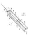
- FIG. 1is a perspective view of a dispenser according to the present invention with a cover taken away.
- FIG. 2is a side view of a front portion of the dispenser in FIG. 1.
- FIG. 3is a schematic side view of two cylinder compartments containing two mutually reactive fluid components in the dispenser of the present invention.
- a dispenser 10 of the present inventionfor dispensing two mutually reactive components, such as fibrinogen and thrombin to be mixed for creating a sealant for medical use, comprises an oblong housing 12 for receiving therein two parallel cylinders 14 , 16 containing the two reactive fluid components.
- a first, rear piston 18 , 20is moveable forwardly in its respective cylinder 14 , 16 from an initial rear position (FIG. 3), in which the cylinders 14 , 16 are fully filled, by means of a respective piston rod 22 , 24 extending rearwardly a distance corresponding at least to the intended maximal forward stroke of the pistons 18 , 20 in the cylinders 14 , 16 .
- the piston rods 22 , 24are interconnected by a plate member 26 at a rear end thereof so as to be able of performing a simultaneous forward displacement of the pistons 18 , 20 in the cylinders to thereby simultaneously discharge the two fluid components through respective outlet channels 28 , 30 extending through a common frontal hub portion 32 .
- a mixing appliance 33for example of the kind described in SE-A-0100091-8, may be detachably mounted to the hub portion 32 , as shown in FIG. 1.
- a forward piston 34 , 36is, in an initial rear position thereof in the respective cylinder, blocking the outlet channels 28 , 30 for sealing the content in the cylinders before the initial use.
- the forward sealing pistons 34 , 36will be moved to a forward position in which they allow for a free fluid communication between the outlet channels 28 , 30 and the interior of the cylinders 14 , 16 via a bypass 28 a and 30 a.
- the dispenser 10 of the present inventionhas a new type of actuating device for simultaneously displacing the pistons 18 , 20 in their respective cylinders 14 , 16 .
- the actuating devicecomprises a rotatable drum 38 journalled for rotation about an axis transverse to the longitudinal extension of the dispenser 10 at a front portion of the housing 12 .
- the drum 38is biased by a torsion spring, schematically indicated at 40 in FIG. 2, so as to be capable of winding up at least one cord or string 42 , 44 connected to the plate member 26 at the rear end of the piston rods 22 , 24 of the respective cylinder 14 , 16 .
- a brake shoe 46is normally frictionally engaging the drum 38 for preventing rotation thereof by means of a compression spring 48 biasing the shoe 46 .
- the brake shoe 46may be disengaged from the drum 38 by depressing a push rod 50 against the action of the spring 48 thereby allowing the torsion spring 40 to rotate the drum 38 for winding up the cords 42 , 44 thereon and hence causing the first pistons 18 , 20 to perform a forward movement in the cylinders 14 , 16 for dispensing a desired amount of the respective reactive fluid components to the mixing appliance 33 .
- the initial displacement of the first pistons 18 , 20will first cause the forward pistons 34 , 36 to move from a sealing position to a forward position in which they open up the fluid communication between the outlet channels 28 , 30 and the interior of the cylinders 14 , 16 via the bypasses 28 a , 30 a.
- the above-described dispenser 10is structurally simple and compact and is easy to manipulate for accurate application of a mixed composition to an object owing to the fact that the dispenser may be hand-held in the vicinity of the outlet end thereof while at the same time controlling the discharge of the composition by depressing the push rod 50 with e.g. the thumb.
Landscapes
- Health & Medical Sciences (AREA)
- Engineering & Computer Science (AREA)
- Life Sciences & Earth Sciences (AREA)
- Mechanical Engineering (AREA)
- Surgery (AREA)
- Medical Informatics (AREA)
- Biomedical Technology (AREA)
- Heart & Thoracic Surgery (AREA)
- Nuclear Medicine, Radiotherapy & Molecular Imaging (AREA)
- Molecular Biology (AREA)
- Animal Behavior & Ethology (AREA)
- General Health & Medical Sciences (AREA)
- Public Health (AREA)
- Veterinary Medicine (AREA)
- Coating Apparatus (AREA)
- Infusion, Injection, And Reservoir Apparatuses (AREA)
- Processing And Handling Of Plastics And Other Materials For Molding In General (AREA)
Abstract
Description
- This application claims priority from Swedish Patent Application No. 0102288-8, filed Jun. 27, 2001, the entire content of which is incorporated herein by reference.[0001]
- The present invention relates in general to a dispenser comprising at least two parallel, hollow cylinders for supplying different mutually reactive components to a mixing device located downstream of said cylinders; a respective first piston moveable in each of the cylinders and displaceable by a piston rod connected to the respective piston; said pistons rods being interconnected for simultaneous dispensing of the components contained in the cylinders, when the piston rods and pistons are displaced in the cylinders towards a respective outlet therein; and a means for actuating the pistons rods to perform a forward stroke of the pistons in their respective cylinders for dispensing an amount of said reactive components to the mixing device, said actuating means comprising a spring member adapted to act on the piston rods, and a manually operable brake member for controlling the force of the spring acting on the piston rods.[0002]
- In particular, but not exclusively, the present invention relates to a dispenser of the above mentioned kind for supplying two mutually reactive sealant components, such as fibrinogen and thrombin, to a mixing device for applying an accurately mixed solution of such components to biological tissue, for example for effecting hemostasis or for any other type of therapeutic objective.[0003]
- Various types of dispensers for dispensing a two-component fluid mixture are known. For example, WO 98/40115 discloses a dispenser of the kind mentioned in the introductory portion above. The dispenser has the shape of a pistol with a handle at the rear end thereof. A compression coil spring acts on the rear part of the piston rods via a slide, and one arm of a two-armed lever mounted at the handle acts as a brake on the slide to control the spring force exerted on the piston rods to thereby control the discharge of the fluid contents in the containers. Although this pistol-shaped dispenser is mechanically simple, it may in some instances be awkward and difficult to manipulate accurately, when a precise application of the dispensed fluid mixture is required.[0004]
- It is an object of the present invention to provide a dispenser, which is very compact in size and easy to manipulate carefully and accurately in narrow spaces. The dispenser is preferably designed to be hand-held like a pencil with easy finger access to a brake-deactivating knob and may be disposable or refilled after emptying of the cylinder contents.[0005]
- For this purpose the dispenser of the present invention, as described above by way of introduction, is characterized in that the actuating means comprises at least one rotatable member biased in a rotational direction by a torsion spring, and at least one flexible string attached, at a first end thereof, to the rotatable member so as to be wound thereon, and, at a second end thereof, to an element connected to the piston rods, wherein the manually operable brake means is arranged to normally act on the rotatable member to hold it still, but, when deactivated, adapted to release the rotatable member to thereby wind the string upon the rotatable member while simultaneously causing the pistons to perform a forward stroke for dispensing the reactive components to the mixing device.[0006]
- Other features and structural details of the dispenser of the present invention will be set forth in the dependent claims and described in the following description under reference to the accompanying drawings.[0007]
- Unless otherwise defined, all technical and scientific terms used herein have the same meaning as commonly understood by one of ordinary skill in the art to which this invention belongs. Suitable methods and materials are described below, although methods and materials similar or equivalent to those described herein can also be used in the practice or testing of the present invention. All publications, patent applications, patents, and other references mentioned herein are incorporated by reference in their entirety. In case of conflict, the present specification, including definitions, will control. In addition, the materials, methods, and examples are illustrative only and not intended to be limiting.[0008]
- FIG. 1 is a perspective view of a dispenser according to the present invention with a cover taken away.[0009]
- FIG. 2 is a side view of a front portion of the dispenser in FIG. 1.[0010]
- FIG. 3 is a schematic side view of two cylinder compartments containing two mutually reactive fluid components in the dispenser of the present invention.[0011]
- As shown in FIG. 1, a[0012]
dispenser 10 of the present invention for dispensing two mutually reactive components, such as fibrinogen and thrombin to be mixed for creating a sealant for medical use, comprises anoblong housing 12 for receiving therein twoparallel cylinders rear piston respective cylinder cylinders respective piston rod pistons cylinders piston rods plate member 26 at a rear end thereof so as to be able of performing a simultaneous forward displacement of thepistons respective outlet channels frontal hub portion 32. Amixing appliance 33, for example of the kind described in SE-A-0100091-8, may be detachably mounted to thehub portion 32, as shown in FIG. 1. - As shown in FIG. 3, a[0013]
forward piston outlet channels rear pistons forward sealing pistons outlet channels cylinders bypass - Furthermore, the[0014]
dispenser 10 of the present invention has a new type of actuating device for simultaneously displacing thepistons respective cylinders rotatable drum 38 journalled for rotation about an axis transverse to the longitudinal extension of thedispenser 10 at a front portion of thehousing 12. Thedrum 38 is biased by a torsion spring, schematically indicated at40 in FIG. 2, so as to be capable of winding up at least one cord orstring plate member 26 at the rear end of thepiston rods respective cylinder brake shoe 46 is normally frictionally engaging thedrum 38 for preventing rotation thereof by means of acompression spring 48 biasing theshoe 46. Thebrake shoe 46 may be disengaged from thedrum 38 by depressing apush rod 50 against the action of thespring 48 thereby allowing thetorsion spring 40 to rotate thedrum 38 for winding up thecords first pistons cylinders mixing appliance 33. As described above, the initial displacement of thefirst pistons forward pistons outlet channels cylinders bypasses - The above-described[0015]
dispenser 10 is structurally simple and compact and is easy to manipulate for accurate application of a mixed composition to an object owing to the fact that the dispenser may be hand-held in the vicinity of the outlet end thereof while at the same time controlling the discharge of the composition by depressing thepush rod 50 with e.g. the thumb. - It is to be understood that, while the invention has been described in conjunction with the detailed description thereof, the foregoing description is intended to illustrate and not limit the scope of the invention. Other aspects, advantages, and modifications of the invention are within the scope of the claims set forth below.[0016]
Claims (21)
1. A dispenser comprising:
at least two parallel, hollow cylinders for supplying different mutually reactive components to a mixing device located downstream of said cylinders;
a respective first piston moveable in each of the cylinders and displaceable by a piston rod connected to the respective piston;
said pistons rods being interconnected for simultaneous dispensing of the components contained in the cylinders, when the piston rods and pistons are displaced in the cylinders towards a respective outlet therein; and
a means for actuating the pistons rods to perform a forward stroke of the pistons in their respective cylinders for dispensing an amount of said reactive components to the mixing device,
said actuating means comprising a spring member adapted to act on the piston rods, and a manually operable brake member for controlling the force of the spring acting on the piston rods, wherein said actuating means further comprises:
at least one rotatable member biased in a rotational direction by a torsion spring, and
at least one flexible string attached, at a first end thereof, to the rotatable member so as to be wound thereon, and at a second end thereof to an element connected to the piston rods, wherein the manually operable brake member is arranged to normally act on the rotatable member to hold it still, but, when deactivated, adapted to release the rotatable member to thereby wind the string upon the rotatable member while simultaneously causing the pistons to perform a forward stroke for dispensing the reactive components to the mixing device.
2. The dispenser ofclaim 1 , wherein the brake member and the rotatable member are located in the vicinity of a forward end of the cylinders, and that the rotatable member is journalled so as to be able to rotate about an axis transverse to a longitudinal extension of the cylinders.
3. The dispenser ofclaim 2 , wherein the brake member comprises a brake shoe biased by a spring to normally frictionally engage the rotatable member to a locked position, said brake shoe being moveable against the action of said spring by means of a rod provided with a push button so as to release the rotatable member and allowing it to rotate and perform a pulling action on the piston rods by means of the string.
4. The dispenser ofclaim 1 , wherein the cylinders and the piston rods protruding from a rear end of the cylinders are accommodated in a common oblong housing.
5. The dispenser ofclaim 2 , wherein the cylinders and the piston rods protruding from a rear end of the cylinders are accommodated in a common oblong housing.
6. The dispenser ofclaim 3 , wherein the cylinders and the piston rods protruding from a rear end of the cylinders are accommodated in a common oblong housing.
7. The dispenser ofclaim 1 , wherein each cylinder, at a forward end thereof, houses a second piston, which in a fully filled state of the respective cylinder seals the outlet thereof, and which upon an initial displacement of the respective first piston opens a bypass channel thereby bringing the interior of the cylinder into fluid communication with said outlet.
8. The dispenser ofclaim 2 , wherein each cylinder, at a forward end thereof, houses a second piston, which in a fully filled state of the respective cylinder seals the outlet thereof, and which upon an initial displacement of the respective first piston opens a bypass channel thereby bringing the interior of the cylinder into fluid communication with said outlet.
9. The dispenser ofclaim 3 , wherein each cylinder, at a forward end thereof, houses a second piston, which in a fully filled state of the respective cylinder seals the outlet thereof, and which upon an initial displacement of the respective first piston opens a bypass channel thereby bringing the interior of the cylinder into fluid communication with said outlet.
10. The dispenser ofclaim 4 , wherein each cylinder, at a forward end thereof, houses a second piston, which in a fully filled state of the respective cylinder seals the outlet thereof, and which upon an initial displacement of the respective first piston opens a bypass channel thereby bringing the interior of the cylinder into fluid communication with said outlet.
11. The dispenser ofclaim 5 , wherein each cylinder, at a forward end thereof, houses a second piston, which in a fully filled state of the respective cylinder seals the outlet thereof, and which upon an initial displacement of the respective first piston opens a bypass channel thereby bringing the interior of the cylinder into fluid communication with said outlet.
12. The dispenser ofclaim 6 , wherein each cylinder, at a forward end thereof, houses a second piston, which in a fully filled state of the respective cylinder seals the outlet thereof, and which upon an initial displacement of the respective first piston opens a bypass channel thereby bringing the interior of the cylinder into fluid communication with said outlet.
13. The dispenser ofclaim 4 , wherein the outlets of the cylinders extend through a common hub at the front end of the housing.
14. The dispenser ofclaim 5 , wherein the outlets of the cylinders extend through a common hub at the front end of the housing.
15. The dispenser ofclaim 6 , wherein the outlets of the cylinders extend through a common hub at the front end of the housing.
16. The dispenser ofclaim 7 , wherein the outlets of the cylinders extend through a common hub at the front end of the housing.
17. The dispenser ofclaim 8 , wherein the outlets of the cylinders extend through a common hub at the front end of the housing.
18. The dispenser ofclaim 9 , wherein the outlets of the cylinders extend through a common hub at the front end of the housing.
19. The dispenser ofclaim 10 , wherein the outlets of the cylinders extend through a common hub at the front end of the housing.
20. The dispenser ofclaim 11 , wherein the outlets of the cylinders extend through a common hub at the front end of the housing.
21. The dispenser ofclaim 12 , wherein the outlets of the cylinders extend through a common hub at the front end of the housing.
Applications Claiming Priority (3)
| Application Number | Priority Date | Filing Date | Title |
|---|---|---|---|
| SE0102288 | 2001-06-27 | ||
| SE0102288-8 | 2001-06-27 | ||
| SE0102288ASE0102288D0 (en) | 2001-06-27 | 2001-06-27 | Dispenser |
Publications (2)
| Publication Number | Publication Date |
|---|---|
| US20030071063A1true US20030071063A1 (en) | 2003-04-17 |
| US6708847B2 US6708847B2 (en) | 2004-03-23 |
Family
ID=20284638
Family Applications (1)
| Application Number | Title | Priority Date | Filing Date |
|---|---|---|---|
| US10/185,975Expired - Fee RelatedUS6708847B2 (en) | 2001-06-27 | 2002-06-27 | Dispenser for mixing then dispensing multiple components |
Country Status (6)
| Country | Link |
|---|---|
| US (1) | US6708847B2 (en) |
| EP (1) | EP1399070A1 (en) |
| JP (1) | JP2004530506A (en) |
| CA (1) | CA2451110A1 (en) |
| SE (1) | SE0102288D0 (en) |
| WO (1) | WO2003002005A1 (en) |
Families Citing this family (5)
| Publication number | Priority date | Publication date | Assignee | Title |
|---|---|---|---|---|
| DE102005041962B3 (en)* | 2005-09-03 | 2007-03-01 | Kettenbach Gmbh & Co. Kg | Cartridge for storing e.g. dental casting compound, has discharge opening whose height in axial direction of cylindrical pipe is larger than axial length of interlocking plunger that is arranged in pipe |
| US8197545B2 (en)* | 2005-10-27 | 2012-06-12 | Depuy Spine, Inc. | Nucleus augmentation delivery device and technique |
| US11739166B2 (en) | 2020-07-02 | 2023-08-29 | Davol Inc. | Reactive polysaccharide-based hemostatic agent |
| US12161777B2 (en) | 2020-07-02 | 2024-12-10 | Davol Inc. | Flowable hemostatic suspension |
| WO2022146917A1 (en) | 2020-12-28 | 2022-07-07 | Davol Inc. | Reactive dry powdered hemostatic materials comprising a protein and a multifunctionalized modified polyethylene glycol based crosslinking agent |
Citations (5)
| Publication number | Priority date | Publication date | Assignee | Title |
|---|---|---|---|---|
| US2240046A (en)* | 1939-09-25 | 1941-04-29 | Marra Anthony | Liquid gun |
| US3774809A (en)* | 1971-07-12 | 1973-11-27 | F Bratton | Containers for extrudable materials |
| US4957223A (en)* | 1989-08-14 | 1990-09-18 | Moishe Beilush | Dispenser gun |
| US4979942A (en)* | 1989-10-16 | 1990-12-25 | Johnson & Johnson Medical, Inc. | Two component syringe delivery system |
| US5290259A (en)* | 1993-02-18 | 1994-03-01 | Ultradent Products, Inc. | Double syringe delivery system |
Family Cites Families (6)
| Publication number | Priority date | Publication date | Assignee | Title |
|---|---|---|---|---|
| US5116315A (en)* | 1989-10-03 | 1992-05-26 | Hemaedics, Inc. | Biological syringe system |
| DK166691D0 (en)* | 1991-09-30 | 1991-09-30 | Unes As | MULTI-COMPONENT PROJECT |
| US5975367A (en)* | 1996-09-27 | 1999-11-02 | Thermogenesis Corp. | Fibrin glue line and dot dispenser |
| US6783514B2 (en)* | 1997-01-31 | 2004-08-31 | United States Surgical Corporation | Fibrin sealant applicator |
| US6223936B1 (en)* | 1997-03-10 | 2001-05-01 | Disetronic Licensing Ag | Device for dispensing fluids |
| US6047861A (en)* | 1998-04-15 | 2000-04-11 | Vir Engineering, Inc. | Two component fluid dispenser |
- 2001
- 2001-06-27SESE0102288Apatent/SE0102288D0/enunknown
- 2002
- 2002-06-19JPJP2003508250Apatent/JP2004530506A/ennot_activeAbandoned
- 2002-06-19EPEP02739047Apatent/EP1399070A1/ennot_activeWithdrawn
- 2002-06-19WOPCT/SE2002/001198patent/WO2003002005A1/ennot_activeApplication Discontinuation
- 2002-06-19CACA002451110Apatent/CA2451110A1/ennot_activeAbandoned
- 2002-06-27USUS10/185,975patent/US6708847B2/ennot_activeExpired - Fee Related
Patent Citations (5)
| Publication number | Priority date | Publication date | Assignee | Title |
|---|---|---|---|---|
| US2240046A (en)* | 1939-09-25 | 1941-04-29 | Marra Anthony | Liquid gun |
| US3774809A (en)* | 1971-07-12 | 1973-11-27 | F Bratton | Containers for extrudable materials |
| US4957223A (en)* | 1989-08-14 | 1990-09-18 | Moishe Beilush | Dispenser gun |
| US4979942A (en)* | 1989-10-16 | 1990-12-25 | Johnson & Johnson Medical, Inc. | Two component syringe delivery system |
| US5290259A (en)* | 1993-02-18 | 1994-03-01 | Ultradent Products, Inc. | Double syringe delivery system |
Also Published As
| Publication number | Publication date |
|---|---|
| WO2003002005A1 (en) | 2003-01-09 |
| CA2451110A1 (en) | 2003-01-09 |
| EP1399070A1 (en) | 2004-03-24 |
| US6708847B2 (en) | 2004-03-23 |
| JP2004530506A (en) | 2004-10-07 |
| SE0102288D0 (en) | 2001-06-27 |
Similar Documents
| Publication | Publication Date | Title |
|---|---|---|
| FI107888B (en) | Distribution device for distribution of at least two liquids | |
| US9179958B2 (en) | Dispensing instrument | |
| CA2485487C (en) | Wound closure material applicator | |
| US6007515A (en) | Controlled action, manually operable fluid application | |
| US8714409B2 (en) | Dispensing cartridge | |
| US8590747B2 (en) | Multiple cartridge dispenser with rotating driver | |
| CA2737732C (en) | Cartridge system with compressed gas cartridge | |
| US20100206905A1 (en) | Dual fluid dispenser | |
| US20110108573A1 (en) | Dispensing assembly comprising a cartridge with bag | |
| CA2091318A1 (en) | Endoscopic material delivery device | |
| US6708847B2 (en) | Dispenser for mixing then dispensing multiple components | |
| US20110278375A1 (en) | Discharge apparatus having compressed gas support | |
| US5871354A (en) | Applicator for dental filling materials | |
| AU2002311729A1 (en) | Dispenser | |
| EP1761194B1 (en) | Dispensing cartridge comprising a locking assembly | |
| US20070017929A1 (en) | Re-usable dispensing aid for a semi-solid preparation packaged in a bag | |
| JP2001518387A (en) | Hand-operated fluid applicator with controlled operation | |
| MXPA00003389A (en) | Controlled action, manually operable fluid applicator |
Legal Events
| Date | Code | Title | Description |
|---|---|---|---|
| AS | Assignment | Owner name:BIOVITRUM AB, SWEDEN Free format text:ASSIGNMENT OF ASSIGNORS INTEREST;ASSIGNOR:LJUNGQUIST, OLLE;REEL/FRAME:013383/0740 Effective date:20020923 | |
| CC | Certificate of correction | ||
| REMI | Maintenance fee reminder mailed | ||
| LAPS | Lapse for failure to pay maintenance fees | ||
| STCH | Information on status: patent discontinuation | Free format text:PATENT EXPIRED DUE TO NONPAYMENT OF MAINTENANCE FEES UNDER 37 CFR 1.362 | |
| FP | Lapsed due to failure to pay maintenance fee | Effective date:20080323 |