US20030067685A1 - Optical device - Google Patents
Optical deviceDownload PDFInfo
- Publication number
- US20030067685A1 US20030067685A1US09/971,906US97190601AUS2003067685A1US 20030067685 A1US20030067685 A1US 20030067685A1US 97190601 AUS97190601 AUS 97190601AUS 2003067685 A1US2003067685 A1US 2003067685A1
- Authority
- US
- United States
- Prior art keywords
- optical
- light
- transmissive substrate
- expander
- optical device
- Prior art date
- Legal status (The legal status is an assumption and is not a legal conclusion. Google has not performed a legal analysis and makes no representation as to the accuracy of the status listed.)
- Granted
Links
- 230000003287optical effectEffects0.000titleclaimsabstractdescription324
- 239000000758substrateSubstances0.000claimsabstractdescription169
- 238000000034methodMethods0.000claimsdescription111
- 238000000651laser trappingMethods0.000claimsdescription49
- 230000005540biological transmissionEffects0.000claimsdescription10
- 230000001427coherent effectEffects0.000claimsdescription9
- 238000004049embossingMethods0.000claimsdescription8
- 238000005530etchingMethods0.000claimsdescription8
- 239000011521glassSubstances0.000claimsdescription7
- 238000001459lithographyMethods0.000claimsdescription7
- 229920003023plasticPolymers0.000claimsdescription7
- 230000000644propagated effectEffects0.000claimsdescription6
- 238000004519manufacturing processMethods0.000claimsdescription4
- 230000001902propagating effectEffects0.000claimsdescription2
- 239000011159matrix materialSubstances0.000description4
- 230000008569processEffects0.000description4
- 230000004075alterationEffects0.000description3
- 230000008901benefitEffects0.000description3
- 238000010276constructionMethods0.000description3
- 239000006185dispersionSubstances0.000description3
- 238000003384imaging methodMethods0.000description3
- 239000000463materialSubstances0.000description3
- 239000004973liquid crystal related substanceSubstances0.000description2
- 238000012986modificationMethods0.000description2
- 230000004048modificationEffects0.000description2
- 230000037361pathwayEffects0.000description2
- 230000001413cellular effectEffects0.000description1
- 239000003086colorantSubstances0.000description1
- 239000000470constituentSubstances0.000description1
- 230000007547defectEffects0.000description1
- 238000006073displacement reactionMethods0.000description1
- 238000005516engineering processMethods0.000description1
- 239000000835fiberSubstances0.000description1
- 238000010348incorporationMethods0.000description1
- 230000000717retained effectEffects0.000description1
Images


Classifications
- G—PHYSICS
- G02—OPTICS
- G02B—OPTICAL ELEMENTS, SYSTEMS OR APPARATUS
- G02B27/00—Optical systems or apparatus not provided for by any of the groups G02B1/00 - G02B26/00, G02B30/00
- G02B27/0081—Optical systems or apparatus not provided for by any of the groups G02B1/00 - G02B26/00, G02B30/00 with means for altering, e.g. enlarging, the entrance or exit pupil
- G—PHYSICS
- G02—OPTICS
- G02B—OPTICAL ELEMENTS, SYSTEMS OR APPARATUS
- G02B5/00—Optical elements other than lenses
- G02B5/32—Holograms used as optical elements
- G—PHYSICS
- G02—OPTICS
- G02B—OPTICAL ELEMENTS, SYSTEMS OR APPARATUS
- G02B6/00—Light guides; Structural details of arrangements comprising light guides and other optical elements, e.g. couplings
- G02B6/0001—Light guides; Structural details of arrangements comprising light guides and other optical elements, e.g. couplings specially adapted for lighting devices or systems
- G02B6/0011—Light guides; Structural details of arrangements comprising light guides and other optical elements, e.g. couplings specially adapted for lighting devices or systems the light guides being planar or of plate-like form
- G02B6/0033—Means for improving the coupling-out of light from the light guide
- G02B6/0035—Means for improving the coupling-out of light from the light guide provided on the surface of the light guide or in the bulk of it
- G02B6/0038—Linear indentations or grooves, e.g. arc-shaped grooves or meandering grooves, extending over the full length or width of the light guide
Definitions
- the present inventionrelates to a compact optical device and, more particularly, to a compact optical device which can be used in personal hand-held devices, such as personal digital assistant (PDA), portable telephones and the like.
- PDApersonal digital assistant
- An electronic displaymay provide a real image, the size of which is determined by the physical size of the display device, or a virtual image, the size of which may extend the dimensions of the display device.
- a real imageis defined as an image, projected on a viewing surface positioned at the location of the image, and observed by an unaided human eye.
- Examples of real image displaysinclude a cathode ray tube (CRT) or a liquid crystal display (LCD).
- CRTcathode ray tube
- LCDliquid crystal display
- desktop computer systems and workplace computing equipmentutilize CRT display screens to display images for a user.
- the CRT displaysare heavy, bulky, and not easily miniaturized.
- a laptop, a notebook, or a palm computerflat-panel display is typically used.
- the flat-panel displaymay use LCD technology implemented as passive matrix or active matrix panel.
- the passive matrix LCD panelconsists of a grid of horizontal and vertical wires. Each intersection of the grid constitutes a single pixel, and is controlled by a LCD element.
- the LCD elementeither allows light through or blocks the light.
- the active matrix paneluses a transistor to control each pixel, and is more expensive.
- the flat-panelsare also used for miniature image display systems because of their compactness and energy efficiency compared to the CRT displays.
- Various configurations of miniature display systems using flat-panel display and reflective lighting techniquecan be found in U.S. Pat. No. 5,808,800.
- Small size real image displayshave a relatively small surface area on which to present a real image, thus have limited capability for providing sufficient information to the user. In other words, because of the limited resolution of the human eye, the amount of details resolved from a small size real image may be insufficient.
- a virtual imageis defined as an image, which cannot be projected onto a viewing surface, since no light ray connects the image and an observer.
- a virtual imagecan only be seen through an optic element, for example a typical virtual image can be obtained from an object placed in front of a converging lens, between the lens and its focal point. Light rays, which are reflected from an individual point on the object, diverge when passing through the lens, thus no two rays share two endpoints. An observer, viewing from the other side of the lens would perceive an image, which is located behind the object, hence enlarged.
- a virtual image of an object, positioned at the focal plane of a lensis said to be projected to infinity.
- holographic optical elementshave been used in portable virtual image displays.
- Holographic optical elementsserve as an imaging lens and a combiner where a two-dimensional, quasi-monochromatic display is imaged to infinity and reflected into the eye of an observer.
- a common problem to all types of holographic optical elementsis their relatively high chromatic dispersion. This is a major drawback in applications where the light source is not purely monochromatic.
- Another drawback of some of these displaysis the lack of coherence between the geometry of the image and the geometry of the holographic optical element, which causes aberrations in the image array that decrease the image quality.
- New designswhich typically deal with a single holographic optical element, compensate for the geometric and chromatic aberrations by using non-spherical waves rather than simple spherical waves for recording; however, they do not overcome the chromatic dispersion problem.
- the overall optical systemsare usually very complicated and difficult to manufacture.
- the eye-motion-box of the optical viewing angles resulting from these designsis usually very small, typically less than 10 mm. Hence, the performance of the optical system is very sensitive, even to small movements of the visor relative to the eye of the viewer.
- a readout light sourcemust be located at some distance from the hologram, in order to illuminate its entire surface.
- Such configurationslead to holographic display systems which are bulky, space-consuming and sometimes inconvenient to use.
- International Patent Application No. WO 95/11473discloses compact holographic optical device in which both the aberrations and chromatic dispersions are minimized, and the readout light source must not be located at some distance from the hologram.
- the disclosed holographic optical devicemay also act as a beam expander for magnifying a narrow, collimated beam into a beam of larger diameter.
- an optical devicefor enlarging an eye box, the optical device comprising: (a) a first optical expander being carried by, or formed in, a first light-transmissive substrate engaging a first plane; and (b) a second optical expander being carried by, or formed in, a second light-transmissive substrate engaging a second plane being spaced apart from the first plane; the first and the second optical expanders being designed and configured such that light passing through the first optical expander is expanded in a first dimension, enters the second light-transmissive substrate, through the second optical expander and exits from the second light-transmissive substrate expanded in a second dimension, hence enlarging an eye box of the optical device in both the first and the second dimensions.
- a method of enlarging an eye boxcomprising: (a) expanding inputted light rays in a first dimension by passing the light rays through a first optical expander engaging a first plane; and (b) expanding the inputted light rays in a second dimension by passing the light rays through a second optical expander engaging a second plane being spaced apart from the first plane; hence enlarging the eye box in both the first and the second dimensions.
- the methodfurther comprising prior to step (b): passing the light rays through an optical trapping element engaging the second plane and being laterally displaced from the second optical expander thereby propagating the light rays through a light guide in a direction of the second optical expander.
- the methodfurther comprising collimating the inputted light.
- the collimatingis done by a converging lens.
- the collimatingis done by a diffractive optical element.
- the methodfurther comprising redirecting the inputted light, so as to reduce a distance between the first plane and an input light source producing the inputted light.
- the redirectingis done by a 45 degrees mirror.
- a method of manufacturing an optical device for enlarging an eye boxcomprising: (a) positioning a first light-transmissive substrate having a first optical expander carried thereby, or formed therein in a first plane; and (b) positioning a second light-transmissive substrate having a second optical expander carried thereby, or formed therein, the first and the second optical expanders designed and configured such that light passing through the first optical expander is expanded in a first dimension, enters the second light-transmissive substrate, through the second optical expander and exits from the second light-transmissive substrate expanded in a second dimension.
- an optical devicefor enlarging an eye box, the optical device comprising: a first light-transmissive substrate engaging a first plane; and a second light-transmissive substrate engaging a second plane being spaced apart from the first plane; the first and second light-transmissive substrates designed and configured such that light passing through the device is first expanded in a first dimension within the first light-transmissive substrate, and then expanded in a second dimension within the second light-transmissive substrate, hence enlarging an eye box of the optical device in both the first and the second dimensions.
- the optical devicefurther comprising an input light source for producing the light.
- the optical devicefurther comprising: (c) an optical trapping element being carried by, or formed in, the second light-transmissive substrate and being laterally displaced from the second optical expander;
- the optical devicefurther comprising a collimator for collimating the light produced by the input light source.
- the optical devicefurther comprising at least one optical element for redirecting light rays, positioned so as to reduce an overall size of the optical device.
- first and second planesare substantially parallel.
- the first and second dimensionsare substantially orthogonal.
- the input light sourcecomprises an input display source, hence the light constitutes an image.
- first and second optical expanderssubstantially parallel one another and at least partially overlap in a direction substantially perpendicular both thereto.
- the first optical expanderis configured and designed so as to transform spherical waves emanating from the input display source into plane waves, to at least partially diffract the plane waves, and to reflect the plane waves within the first light-transmissive substrate, hence to expand the image in the first dimension.
- the second optical expanderis configured and designed so as to at least partially diffract at least a portion of light rays exiting the first light-transmissive substrate, hence to expand the image in the second dimension, and to couple the light rays out of the second light-transmissive substrate in a direction of an eye of a user.
- the optical trapping elementis configured and designed so as to trap at least a portion of light rays exiting the first light-transmissive substrate, inside the second light-transmissive substrate by substantially total internal reflection, hence to propagate the plurality of light rays in a direction of the second optical expander.
- the second optical expanderis configured and designed so as to at least partially diffract the plurality of light rays, propagated through the second light-transmissive substrate, hence to expand the image in the second dimension, and to couple the plurality of light rays out of the second light-transmissive substrate in a direction of an eye of a user.
- each of the first and the second optical expandersis embodied in the light-transmissive substrates by recording an interference pattern of two mutually coherent optical waves.
- the interference patterncomprise linear diffraction gratings.
- the linear diffraction gratings of the second optical expanderis substantially orthogonal to the linear diffraction gratings of the first optical expander.
- the linear diffraction gratings of the first and second optical expandersare each independently selected from the group consisting of reflection linear diffraction gratings and transmission linear diffraction gratings.
- the recordingis effected by a procedure selected from a group consisting of computer-generated masks, lithography, embossing, etching and direct writing.
- the optical trapping elementis embodied in the light-transmissive substrates by recording an interference pattern of two mutually coherent optical waves.
- the linear diffraction gratings of the optical trapping elementis substantially orthogonal to the linear diffraction gratings of the first optical expander.
- the linear diffraction gratings of the optical trapping elementis substantially parallel to the linear diffraction gratings of the second optical expander.
- the linear diffraction gratings of the second optical expander and the optical trapping elementare with equal periodicity.
- each of the first and second light-transmissive substratescomprises a first surface and a second surface.
- the first optical expanderis embodied in the first surface of the first light-transmissive substrate.
- the first optical expanderis embodied in the second surface of the first light-transmissive substrate.
- the collimatorcomprises a converging lens.
- the collimatorcomprises a diffractive optical element carried by, or formed in, the first light-transmissive substrate.
- the at least one optical elementis a 45 degrees mirror.
- each of the first optical expander and the second optical expanderhas a predetermined diffraction efficiency.
- the optical trapping elementhas a predetermined diffraction efficiency.
- the predetermined diffraction efficiencyvaries locally for achieving an output having substantially uniform light intensities.
- the predetermined diffraction efficiencyvaries locally for achieving an output having predefined intensities.
- the first and the second optical expandersare each independently a plurality of linearly stretched mini-prisms, carried by a variable light transmissive surface.
- the optical trapping elementis a plurality of linearly stretched mini-prisms.
- the first light-transmissive substrate and the second light-transmissive substrateare of thickness ranging between about 0.5 mm and about 5 mm.
- the first light-transmissive substrate and the second light-transmissive substrateare each independently selected from the group consisting of glass and transparent plastic.
- the present inventionsuccessfully addresses the shortcomings of the presently known configurations by providing an optical device for enlarging an eye box.
- Implementation of the method and device of the present inventioninvolves performing or completing selected tasks or steps manually, automatically, or a combination thereof.
- several selected stepscould be implemented by hardware or by software on any operating device of any firmware or a combination thereof.
- selected steps of the inventioncould be implemented as a chip or a circuit.
- selected steps of the inventioncould be implemented as a plurality of software instructions being executed by a computer using any suitable operating device.
- selected steps of the method and device of the inventioncould be described as being performed by a data processor, such as a computing platform for executing a plurality of instructions.
- FIG. 1is a three-dimensional view of a prior art planar optical configuration
- FIG. 2 ais a short side view of a device for enlarging an eye-box according to the teachings of the present invention
- FIG. 2 bis a long side view of a device for enlarging an eye-box according to the teachings of the present invention
- FIG. 3is a long side view of a device for enlarging an eye-box further including an optical trapping element according to the teachings of the present invention
- FIG. 4is a long side view of a device for enlarging an eye-box further including a collimator, at least one optical element for redirecting light rays and an input light source, according to the teachings of the present invention
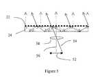
- FIG. 5is a short side schematic illustration of the operation of a first optical expander carried by a first light-transmissive substrate, according to the teachings of the present invention.
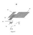
- FIG. 6is an isometric view of a device for enlarging an eye-box, according to the teachings of the present invention.
- the present inventionis of an optical device which can be used to enlarge an eye-box.
- the present inventioncan be used to enlarge an eye-box of a display embodied in e.g., cellular telephones.
- FIGS. 2 - 6 of the drawingsFor purposes of better understanding the present invention, as illustrated in FIGS. 2 - 6 of the drawings, reference is first made to the construction and operation of a prior art display as illustrated in FIG. 1.
- FIG. 1illustrates a three-dimensional view of a planar optical configuration disclosed in International Patent Application No. WO 95/11473, which is referred to herein as device 10 .
- Device 10includes a first holographic optical element 12 , a second holographic optical element 14 and a third holographic optical element 16 , formed in a light-transmissive substrate 18 .
- Second holographic optical element 14is laterally displaced from first holographic optical element 12 .
- the displacement direction of second holographic optical element 14 from first holographic optical element 12is referred to herein as direction ⁇ , and the orthogonal direction to ⁇ is referred to herein as direction ⁇ .
- transverse dimensionsi.e., the dimensions along ⁇ axis, of both second holographic optical element 14 and first holographic optical element 12 are substantially equal, whereas the longitudinal dimension (along ⁇ axis), of second holographic optical element 14 is larger than the longitudinal dimension of first holographic optical element 12 .
- Third holographic optical element 16is further laterally displaced from second holographic optical element 14 in ⁇ direction. Both transverse and longitudinal dimensions of third holographic optical element 16 are substantially equal to the longitudinal dimension of second holographic optical element 14 .
- First holographic optical element 12is illuminated by light, which may be generated by a light source located behind first holographic optical element 12 .
- the illuminating lightis diffracted by first holographic optical element 12 in a manner such that the light is trapped inside light-transmissive substrate 18 and propagates in ⁇ direction therethrough by substantially total internal reflection, as disclosed in International Patent Application No. WO 95/11473.
- the physical phenomenon of total internal reflectionis herein described.
- Equation 1has a solution for O 2 only for ⁇ 1 which is smaller than arcsine of n 2 /n 1 often called the critical angle.
- Equation 1For sufficiently large ⁇ 1 (above the critical angle), no refraction angle ⁇ 2 satisfies Equation 1 and light energy is trapped within light-transmissive substrate. In other words, the light is reflected from the internal surface as if it had stroked a mirror. Under these conditions, total internal reflection is said to take place.
- the propagated lightafter a few reflections within light-transmissive substrate 18 , reaches second holographic optical element 14 , which diffracts the light so that the light propagates, still within light-transmissive substrate 18 , however in ⁇ direction.
- Third holographic optical element 16couples the trapped light outward from light-transmissive substrate 18 , in a direction calculated to reach an eye of a user.
- first holographic optical element 12 and second holographic optical element 14increases the ⁇ axis diameter of the plane waves by a factor which is equal to the ratio between the two longitudinal dimensions.
- second holographic optical element 14 and third holographic optical element 16increases the ⁇ axis diameter of the plane waves by a factor which is equal to the ratio between the two transverse dimensions.
- first, second and third holographic optical elementsexpand an image constituted by the input light in two dimensions, thereby enlarging the eye-box of the display.
- first 12 , second 14 and third 16 holographic optical elementsare configured in a planar geometry, namely engaging a single plane.
- the minimal area of the planeis larger than the sum of areas of the three holographic optical elements.
- device 20While reducing the present invention to practice, it was uncovered that the geometrical limitation of device 10 may be overcome by providing an optical device for enlarging an eye box, referred to herein as device 20 .
- FIGS. 2 a and 2 billustrate, respectively, a first (short) and a second (long) side view of device 20 of the present invention.
- Device 20includes a first optical expander 22 which is carried by, or formed in, a first light-transmissive substrate 24 .
- First optical expander 22 and first light-transmissive substrate 24serve for expanding input light passing therethrough in a first dimension, as further detailed hereinunder. As seen, first light-transmissive substrate 24 engages a first plane.
- Device 20further includes a second optical expander 26 which is carried by, or formed in a second light-transmissive substrate 28 .
- Second optical expander 26 and second light-transmissive substrate 28serve for expanding the light passing therethrough, in a second dimension, as further detailed hereinunder.
- second light-transmissive substrate 28is engaging a second plane, which second plane is spaced apart, preferably about 0.5 mm-2 mm, from the first plane.
- the first plane and the second planeare substantially parallel.
- the planesmay have any other, i.e., non-parallel, mutual position in space.
- the two-plane configuration of device 20ensures that each light-transmissive substrate expands the light in one dimension, whereas the output of first light-transmissive substrate 24 becomes the input of second light-transmissive substrate 28 .
- device 20enlarges an eye box in two dimensions.
- device 20may further include an optical trapping element 30 which is carried by, or formed in, second light-transmissive substrate 28 , and is laterally displaced from second optical expander 26 .
- Optical trapping element 30serves for re-directing the light expanded by first optical expander 22 and first light-transmissive substrate 24 , so as to propagate the light within second light-transmissive substrate 28 in a direction of second optical expander 26 , by substantially total internal reflection.
- optical element 30is a diffractive optical element.
- optical trapping element 30is either included or excluded.
- device 20may further include a collimator 34 , at least one optical element 42 for redirecting light rays and/or an input light source 52 .
- Collimator 34is positioned behind first light-transmissive substrate 24 .
- Collimator 34serves for collimating the input light, if it is not already collimated, prior to impinging on first light-transmissive substrate 24 .
- Any collimating element known in the artmay be used as collimator 34 , for example a converging lens or a diffractive optical element. The purpose of the collimating procedure is for improving the imaging ability.
- a light ray going through a typical converging lens that is normal to the lens and passes through its centerdefines the optical axis.
- the bundle of rays passing through the lenscluster about this axis and may be well imaged by the lens.
- Other collimating meanse.g., a diffractive optical element, may also provide imaging functionality, although for such means the optical axis is not well defined.
- the advantage of a converging lensis due to its symmetry about the optical axis, whereas the advantage of a diffractive optical element is due to its compactness.
- the diffractive optical elementmay be spaced apart, carried by or formed in first light-transmissive substrate 24 .
- collimator 34is a diffractive optical element
- itmay be positioned either on the entry surface of first light-transmissive substrate 24 , as a transmissive diffractive element or on the opposite surface of first light-transmissive substrate 24 as a reflective diffractive element.
- optical element(s) 42are positioned so as to reduce an overall size of device 20 . Some optical devices function better when light sources are placed within a certain distance therefrom. By including optical element 42 , the pathway of the light rays is “folded”, hence optical element 42 allows control over the cross-sectional size of device 20 . According to a preferred embodiment of the present invention optical element 42 may be as simple as a 45 degrees mirror or any other optical element known in the art for redirecting light.
- input light source 52is positioned behind first light-transmissive substrate 24 .
- Input light source 52may reflect or transmit light, impinging first light-transmissive substrate 24 , thereby the light constitutes an image of input light source 52 .
- Input light source 52may be in any form known in the art, such as but not limited to, a flat panel display e.g., LCD, a virtual image produced by other optical device, a fiber bundle guiding image information or an array of organic/inorganic light emitting diodes.
- collimator 34is positioned between input light source 52 and first light-transmissive substrate 24 , for collimating the light as described above.
- first light-transmissive substrate 24 and first optical expander 22are to expand input light in a first dimension.
- FIG. 5is a short side schematic illustration of first optical expander 22 carried by first light-transmissive substrate 24 .
- FIG. 5illustrates an optical pathway of two rays, ray 54 , shown as a solid line in FIG. 5, which is reflected by or transmitted from one end of input light source 52 ; and ray 56 shown as a dotted line in FIG. 5, which is reflected by or transmitted from the center of input light source 52 .
- Ray 54which enters first light-transmissive substrate 24 through its first side, strikes first optical expander 22 , positioned on the second side of first light-transmissive substrate 24 .
- a portion of the light energy carried by ray 54exits to open air directed into second light-transmissive substrate 28 (not shown in FIG. 5).
- the remnant of ray 54splits into two rays, each being redirected through an angle, which causes it to experience substantially total internal reflection from the first side of first light-transmissive substrate 24 .
- each raystrikes first optical expander 22 and partially refracts so that part of the light energy carried by the ray is transmitted through first optical expander 22 and the remnant is redirected, again through an angle which causes it to experience substantially total internal reflection from the first side of first light-transmissive substrate 24 .
- ray 56splits into three rays, one ray is transmitted outwards and two rays are redirected so as to experience substantially total internal reflection from the first side of first light-transmissive substrate 24 , followed by a partial refraction from first optical expander 22 .
- first optical expander 22This process of partial refraction from first optical expander 22 and total reflection from first side of first light-transmissive substrate 24 is repeated for each of the two rays initially produced from each parent incoming ray and redirected by first optical expander 22 .
- the number of reflections that each light ray is subjected tois determined by the thickness of first light-transmissive substrate 24 , specifically, thinner substrate leads to a larger number of reflections.
- the thickness the light-transmissive substratesmay vary between about 0.5 mm and about 5 mm. For any thickness within this range, the captured parts of each incoming ray propagate in opposite directions and retain within first light-transmissive substrate 24 , until the end of first optical expander 22 is reached.
- the above processmay be achieved by positioning first optical expander 22 on the first side of first light-transmissive substrate 24 .
- the energy carried by the light raysis completely redirected from first optical expander 22 and partially reflected upon striking the second side of first light-transmissive substrate 24 .
- each incoming rayis multiplied into a plurality of parallel outgoing rays emerging the second side of first light-transmissive substrate 24 .
- a beam of light passing through first light-transmissive substrate 24 and first optical expander 22is expanded in a manner that one lateral dimension of the outgoing beam is a magnification of the corresponding lateral dimension of the incoming beam.
- the image constituted by the beamis therefore “stretched” or expanded in one dimension.
- the physical shape and design of the devicefavor propagation of the light from input light source 52 through first light-transmissive substrate 24 only in one direction, as opposed to the two opposite directions propagation described above.
- the propagation directioncan be controlled by positioning collimator 34 near one end of first light-transmissive substrate 24 , so that incoming light is forced to propagate towards the other end.
- optical trapping element 30The expanded light entering the entry side of second light-transmissive substrate 28 through optical trapping element 30 is re-directed by trapping element 30 to strike the second side of second light-transmissive substrate 28 through an angle which causes it to experience substantially total internal reflection. Unlike first optical expander 22 , the light ray redirected by optical trapping element 30 is not diffracted out, but rather captured and retained within second light-transmissive substrate 28 .
- the lightpropagates within second light-transmissive substrate 28 , as described above, until it reaches second optical expander 26 . Otherwise, the light emerges from first light-transmissive substrate 24 and impinges directly on second optical expander 26 . In any case, once the light impinges on second optical expander 26 it experiences a series of partial diffractions and total reflections so that the constituent image is “stretched” in a second dimension, in a manner similar to the process of stretching in a first dimension described hereinabove.
- the diameter of the beam emerging from second light-transmissive substrate 28is expanded in two dimension: the diameter is expanded in a first dimension within first light-transmissive substrate 24 and in a second dimension within second light-transmissive substrate 28 .
- first optical expander 22 and second optical expander 26may be manufactured as a linear diffraction grating.
- Such optical elementsare known to allow both redirection and transmission of light striking the grating.
- the angle of redirectionis determined by an appropriate choice of the period of the diffraction grating often called “the grating function”.
- the diffraction efficiencycontrols the energy fraction that is transmitted at each strike of light on the grating.
- the diffraction efficiencymay be predetermined so as to achieve an output having predefined light intensities, in particular the diffraction efficiency may vary locally for providing a substantially uniform light intensities.
- first optical expander 22 and second optical expander 26may be manufactured as a variable light transmissive surface onto which a stack of linearly stretched mini-prisms is located.
- optical trapping element 30may be in any form known in the art for trapping light within a light-transmissive substrate.
- optical trapping element 30may be manufactured as a linear diffraction grating.
- the grating functionmay be any grating function known in the art suitable for propagation by total internal reflection, and is described, e.g., in International Patent Application No. WO 95/11473.
- optical trapping element 30may be manufactured as a stack of linearly stretched mini-prisms.
- the gratingsare substantially orthogonal.
- the diffraction grating of each of the optical expanderscan be embodied within the light-transmissive substrates by recording the interference pattern of two mutually coherent optical waves.
- the gratingcan be recorded by means of computer-generated masks and lithographic techniques, by direct writing techniques, by embossing or etching or by any other procedure known in the art.
- the diffraction gratings of first, second and third diffractive optical elementswhich may be used in any of the preferred embodiments of the invention described herein, may include any combination of reflection linear diffraction gratings and transmission linear diffraction gratings.
- the present inventionalso addresses the problem of enlarging an eye-box of miniature color images. It is a well-known physical phenomenon that lights of different wavelengths (i.e., different colors) diffract on equal diffractive elements through different angles. The principles of maintaining color registration employed by device 20 are herein described.
- the linear gratings of second optical expander 26 and optical trapping element 30are oriented substantially parallel to each other. Further in accordance with a preferred embodiment of the present invention, the gratings of second optical expander 26 and optical trapping element 30 are with equal periodicity. With this optical expanders configuration any achromatic diffraction occurred at optical trapping element 30 , is compensated at second optical expander 26 , and color information may be transmitted without distortion. Similarly, color information is transmitted through first light-transmissive substrate 24 by maintaining grating linearity and periodicity throughout first optical expander 22 .
- first light-transmissive substrate 24 and second light-transmissive substrate 28may each independently be manufactured from any material which enables transmission of visible light therethrough, such as, but not limited to, glass or transparent plastic.
- the index of refraction of the light-transmissive substrates materialsshould be larger than the index of refraction of air, or any other material engaging the inter-substrate spacing.
- a typical width of both light-transmissive substratesranges between from about 20 mm to about 60 mm.
- a typical length of both first optical expander and optical trapping element 30ranges from about 5 mm to about 10 mm.
- a typical length of second optical expander 26ranges from about 40 mm to about 100 mm.
- FIG. 6An isometric view of device 20 is shown in FIG. 6, which illustrates the volume engaged by device 20 .
- the preferred position of input light source 52depends on whether or not optical element 42 is included in device 20 .
- the preferred position in front of optical element 42otherwise the preferred position is behind collimator 34 .
- Both positionsare illustrated in FIG. 6 as a dotted line (with optical element 42 ) and a solid line (without optical element 42 ).
- a typical volume engaged by both light-transmissive substratesis about 10 cubic cm.
- collimator 34 , optical element 42 and input light source 52which is taken to have a typical thickness of a liquid crystal display, the total estimated volume of device 20 is about 13 cubic cm.
Landscapes
- Physics & Mathematics (AREA)
- General Physics & Mathematics (AREA)
- Optics & Photonics (AREA)
- Diffracting Gratings Or Hologram Optical Elements (AREA)
- Microscoopes, Condenser (AREA)
Abstract
Description
- The present invention relates to a compact optical device and, more particularly, to a compact optical device which can be used in personal hand-held devices, such as personal digital assistant (PDA), portable telephones and the like.[0001]
- Miniaturization of electronic devices has always been a continuing objective in the field of electronics. Electronic devices are often equipped with some form of display, which is visible to a user. As these devices reduce in size, there is an increase need for manufacturing compact displays, which are compatible with small size electronic devices. Besides having small dimensions, such displays should not sacrifice image quality, and be available at low cost. By definition the above characteristics are conflicting and many attempts have been made to provide some balanced solution.[0002]
- An electronic display may provide a real image, the size of which is determined by the physical size of the display device, or a virtual image, the size of which may extend the dimensions of the display device.[0003]
- A real image is defined as an image, projected on a viewing surface positioned at the location of the image, and observed by an unaided human eye. Examples of real image displays include a cathode ray tube (CRT) or a liquid crystal display (LCD). Typically, desktop computer systems and workplace computing equipment utilize CRT display screens to display images for a user. The CRT displays are heavy, bulky, and not easily miniaturized. For a laptop, a notebook, or a palm computer, flat-panel display is typically used. The flat-panel display may use LCD technology implemented as passive matrix or active matrix panel. The passive matrix LCD panel consists of a grid of horizontal and vertical wires. Each intersection of the grid constitutes a single pixel, and is controlled by a LCD element. The LCD element either allows light through or blocks the light. The active matrix panel uses a transistor to control each pixel, and is more expensive.[0004]
- The flat-panels are also used for miniature image display systems because of their compactness and energy efficiency compared to the CRT displays. Various configurations of miniature display systems using flat-panel display and reflective lighting technique can be found in U.S. Pat. No. 5,808,800.[0005]
- Small size real image displays have a relatively small surface area on which to present a real image, thus have limited capability for providing sufficient information to the user. In other words, because of the limited resolution of the human eye, the amount of details resolved from a small size real image may be insufficient.[0006]
- By contrast to a real image, a virtual image is defined as an image, which cannot be projected onto a viewing surface, since no light ray connects the image and an observer. A virtual image can only be seen through an optic element, for example a typical virtual image can be obtained from an object placed in front of a converging lens, between the lens and its focal point. Light rays, which are reflected from an individual point on the object, diverge when passing through the lens, thus no two rays share two endpoints. An observer, viewing from the other side of the lens would perceive an image, which is located behind the object, hence enlarged. A virtual image of an object, positioned at the focal plane of a lens, is said to be projected to infinity.[0007]
- Conventional virtual image displays are known to have many shortcomings. For example, such displays have suffered from being too heavy for comfortable use, as well as too large so as to be obtrusive, distracting, and even disorienting. These defects stem from, among other things, the incorporation of relatively large optics systems within the mounting structures, as well as physical designs which fail to adequately take into account important factors as size, shape, weight, etc.[0008]
- Recently, holographic optical elements have been used in portable virtual image displays. Holographic optical elements serve as an imaging lens and a combiner where a two-dimensional, quasi-monochromatic display is imaged to infinity and reflected into the eye of an observer. A common problem to all types of holographic optical elements is their relatively high chromatic dispersion. This is a major drawback in applications where the light source is not purely monochromatic. Another drawback of some of these displays is the lack of coherence between the geometry of the image and the geometry of the holographic optical element, which causes aberrations in the image array that decrease the image quality.[0009]
- New designs, which typically deal with a single holographic optical element, compensate for the geometric and chromatic aberrations by using non-spherical waves rather than simple spherical waves for recording; however, they do not overcome the chromatic dispersion problem. Moreover, with these designs, the overall optical systems are usually very complicated and difficult to manufacture. Furthermore, the eye-motion-box of the optical viewing angles resulting from these designs is usually very small, typically less than 10 mm. Hence, the performance of the optical system is very sensitive, even to small movements of the visor relative to the eye of the viewer.[0010]
- In some conventional holographic displays a readout light source must be located at some distance from the hologram, in order to illuminate its entire surface. Such configurations lead to holographic display systems which are bulky, space-consuming and sometimes inconvenient to use. International Patent Application No. WO 95/11473, the contents of which are hereby incorporated by reference, discloses compact holographic optical device in which both the aberrations and chromatic dispersions are minimized, and the readout light source must not be located at some distance from the hologram. The disclosed holographic optical device may also act as a beam expander for magnifying a narrow, collimated beam into a beam of larger diameter. Although the overall volume of this compact holographic optical device is substantially reduced compared to other known display devices, the compactness is still insufficient for displays of ultra compact electronic systems such as portable telephones and personal digital assistant.[0011]
- There is thus a widely recognized need for, and it would be highly advantageous to have, a compact optical device devoid of the above limitation.[0012]
- According to one aspect of the present invention there is provided an optical device for enlarging an eye box, the optical device comprising: (a) a first optical expander being carried by, or formed in, a first light-transmissive substrate engaging a first plane; and (b) a second optical expander being carried by, or formed in, a second light-transmissive substrate engaging a second plane being spaced apart from the first plane; the first and the second optical expanders being designed and configured such that light passing through the first optical expander is expanded in a first dimension, enters the second light-transmissive substrate, through the second optical expander and exits from the second light-transmissive substrate expanded in a second dimension, hence enlarging an eye box of the optical device in both the first and the second dimensions.[0013]
- According to another aspect of the present invention there is provided a method of enlarging an eye box, the method comprising: (a) expanding inputted light rays in a first dimension by passing the light rays through a first optical expander engaging a first plane; and (b) expanding the inputted light rays in a second dimension by passing the light rays through a second optical expander engaging a second plane being spaced apart from the first plane; hence enlarging the eye box in both the first and the second dimensions.[0014]
- According to further features in preferred embodiments of the invention described below, the method further comprising prior to step (b): passing the light rays through an optical trapping element engaging the second plane and being laterally displaced from the second optical expander thereby propagating the light rays through a light guide in a direction of the second optical expander.[0015]
- According to still further features in the described preferred embodiments the method further comprising collimating the inputted light.[0016]
- According to still further features in the described preferred embodiments the collimating is done by a converging lens.[0017]
- According to still further features in the described preferred embodiments the collimating is done by a diffractive optical element.[0018]
- According to still further features in the described preferred embodiments the method further comprising redirecting the inputted light, so as to reduce a distance between the first plane and an input light source producing the inputted light.[0019]
- According to still further features in the described preferred embodiments the redirecting is done by a[0020]45 degrees mirror.
- According to yet another aspect of the present invention there is provided a method of manufacturing an optical device for enlarging an eye box, the method comprising: (a) positioning a first light-transmissive substrate having a first optical expander carried thereby, or formed therein in a first plane; and (b) positioning a second light-transmissive substrate having a second optical expander carried thereby, or formed therein, the first and the second optical expanders designed and configured such that light passing through the first optical expander is expanded in a first dimension, enters the second light-transmissive substrate, through the second optical expander and exits from the second light-transmissive substrate expanded in a second dimension.[0021]
- According to still another aspect of the present invention there is provided an optical device for enlarging an eye box, the optical device comprising: a first light-transmissive substrate engaging a first plane; and a second light-transmissive substrate engaging a second plane being spaced apart from the first plane; the first and second light-transmissive substrates designed and configured such that light passing through the device is first expanded in a first dimension within the first light-transmissive substrate, and then expanded in a second dimension within the second light-transmissive substrate, hence enlarging an eye box of the optical device in both the first and the second dimensions.[0022]
- According to further features in preferred embodiments of the invention described below, the optical device further comprising an input light source for producing the light.[0023]
- According to still further features in the described preferred embodiments the optical device further comprising: (c) an optical trapping element being carried by, or formed in, the second light-transmissive substrate and being laterally displaced from the second optical expander;[0024]
- According to still further features in the described preferred embodiments the optical device further comprising a collimator for collimating the light produced by the input light source.[0025]
- According to still further features in the described preferred embodiments the optical device further comprising at least one optical element for redirecting light rays, positioned so as to reduce an overall size of the optical device.[0026]
- According to still further features in the described preferred embodiments the first and second planes are substantially parallel.[0027]
- According to still further features in the described preferred embodiments the first and second dimensions are substantially orthogonal.[0028]
- According to still further features in the described preferred embodiments the input light source comprises an input display source, hence the light constitutes an image.[0029]
- According to still further features in the described preferred embodiments the first and second optical expanders substantially parallel one another and at least partially overlap in a direction substantially perpendicular both thereto.[0030]
- According to still further features in the described preferred embodiments the first optical expander is configured and designed so as to transform spherical waves emanating from the input display source into plane waves, to at least partially diffract the plane waves, and to reflect the plane waves within the first light-transmissive substrate, hence to expand the image in the first dimension.[0031]
- According to still further features in the described preferred embodiments the second optical expander is configured and designed so as to at least partially diffract at least a portion of light rays exiting the first light-transmissive substrate, hence to expand the image in the second dimension, and to couple the light rays out of the second light-transmissive substrate in a direction of an eye of a user.[0032]
- According to still further features in the described preferred embodiments the optical trapping element is configured and designed so as to trap at least a portion of light rays exiting the first light-transmissive substrate, inside the second light-transmissive substrate by substantially total internal reflection, hence to propagate the plurality of light rays in a direction of the second optical expander.[0033]
- According to still further features in the described preferred embodiments the second optical expander is configured and designed so as to at least partially diffract the plurality of light rays, propagated through the second light-transmissive substrate, hence to expand the image in the second dimension, and to couple the plurality of light rays out of the second light-transmissive substrate in a direction of an eye of a user.[0034]
- According to still further features in the described preferred embodiments each of the first and the second optical expanders is embodied in the light-transmissive substrates by recording an interference pattern of two mutually coherent optical waves.[0035]
- According to still further features in the described preferred embodiments the interference pattern comprise linear diffraction gratings.[0036]
- According to still further features in the described preferred embodiments the linear diffraction gratings of the second optical expander is substantially orthogonal to the linear diffraction gratings of the first optical expander.[0037]
- According to still further features in the described preferred embodiments the linear diffraction gratings of the first and second optical expanders are each independently selected from the group consisting of reflection linear diffraction gratings and transmission linear diffraction gratings.[0038]
- According to still further features in the described preferred embodiments the recording is effected by a procedure selected from a group consisting of computer-generated masks, lithography, embossing, etching and direct writing.[0039]
- According to still further features in the described preferred embodiments the optical trapping element is embodied in the light-transmissive substrates by recording an interference pattern of two mutually coherent optical waves.[0040]
- According to still further features in the described preferred embodiments the linear diffraction gratings of the optical trapping element is substantially orthogonal to the linear diffraction gratings of the first optical expander.[0041]
- According to still further features in the described preferred embodiments the linear diffraction gratings of the optical trapping element is substantially parallel to the linear diffraction gratings of the second optical expander.[0042]
- According to still further features in the described preferred embodiments the linear diffraction gratings of the second optical expander and the optical trapping element are with equal periodicity.[0043]
- According to still further features in the described preferred embodiments each of the first and second light-transmissive substrates comprises a first surface and a second surface.[0044]
- According to still further features in the described preferred embodiments the first optical expander is embodied in the first surface of the first light-transmissive substrate.[0045]
- According to still further features in the described preferred embodiments the first optical expander is embodied in the second surface of the first light-transmissive substrate.[0046]
- According to still further features in the described preferred embodiments the collimator comprises a converging lens.[0047]
- According to still further features in the described preferred embodiments the collimator comprises a diffractive optical element carried by, or formed in, the first light-transmissive substrate.[0048]
- According to still further features in the described preferred embodiments the at least one optical element is a 45 degrees mirror.[0049]
- According to still further features in the described preferred embodiments each of the first optical expander and the second optical expander has a predetermined diffraction efficiency.[0050]
- According to still further features in the described preferred embodiments the optical trapping element has a predetermined diffraction efficiency.[0051]
- According to still further features in the described preferred embodiments the predetermined diffraction efficiency varies locally for achieving an output having substantially uniform light intensities.[0052]
- According to still further features in the described preferred embodiments the predetermined diffraction efficiency varies locally for achieving an output having predefined intensities.[0053]
- According to still further features in the described preferred embodiments the first and the second optical expanders are each independently a plurality of linearly stretched mini-prisms, carried by a variable light transmissive surface.[0054]
- According to still further features in the described preferred embodiments the optical trapping element is a plurality of linearly stretched mini-prisms.[0055]
- According to still further features in the described preferred embodiments the first light-transmissive substrate and the second light-transmissive substrate are of thickness ranging between about 0.5 mm and about 5 mm.[0056]
- According to still further features in the described preferred embodiments the first light-transmissive substrate and the second light-transmissive substrate are each independently selected from the group consisting of glass and transparent plastic.[0057]
- The present invention successfully addresses the shortcomings of the presently known configurations by providing an optical device for enlarging an eye box.[0058]
- Implementation of the method and device of the present invention involves performing or completing selected tasks or steps manually, automatically, or a combination thereof. Moreover, according to actual instrumentation and equipment of preferred embodiments of the method and device of the present invention, several selected steps could be implemented by hardware or by software on any operating device of any firmware or a combination thereof. For example, as hardware, selected steps of the invention could be implemented as a chip or a circuit. As software, selected steps of the invention could be implemented as a plurality of software instructions being executed by a computer using any suitable operating device. In any case, selected steps of the method and device of the invention could be described as being performed by a data processor, such as a computing platform for executing a plurality of instructions.[0059]
- The invention is herein described, by way of example only, with reference to the accompanying drawings. With specific reference now to the drawings in detail, it is stressed that the particulars shown are by way of example and for purposes of illustrative discussion of the preferred embodiments of the present invention only, and are presented in the cause of providing what is believed to be the most useful and readily understood description of the principles and conceptual aspects of the invention. In this regard, no attempt is made to show structural details of the invention in more detail than is necessary for a fundamental understanding of the invention, the description taken with the drawings making apparent to those skilled in the art how the several forms of the invention may be embodied in practice.[0060]
- In the drawings:[0061]
- FIG. 1 is a three-dimensional view of a prior art planar optical configuration;[0062]
- FIG. 2[0063]ais a short side view of a device for enlarging an eye-box according to the teachings of the present invention;
- FIG. 2[0064]bis a long side view of a device for enlarging an eye-box according to the teachings of the present invention;
- FIG. 3 is a long side view of a device for enlarging an eye-box further including an optical trapping element according to the teachings of the present invention;[0065]
- FIG. 4 is a long side view of a device for enlarging an eye-box further including a collimator, at least one optical element for redirecting light rays and an input light source, according to the teachings of the present invention;[0066]
- FIG. 5 is a short side schematic illustration of the operation of a first optical expander carried by a first light-transmissive substrate, according to the teachings of the present invention; and[0067]
- FIG. 6 is an isometric view of a device for enlarging an eye-box, according to the teachings of the present invention.[0068]
- The present invention is of an optical device which can be used to enlarge an eye-box. Specifically, the present invention can be used to enlarge an eye-box of a display embodied in e.g., cellular telephones.[0069]
- For purposes of better understanding the present invention, as illustrated in FIGS.[0070]2-6 of the drawings, reference is first made to the construction and operation of a prior art display as illustrated in FIG. 1.
- Hence, FIG. 1 illustrates a three-dimensional view of a planar optical configuration disclosed in International Patent Application No. WO 95/11473, which is referred to herein as device[0071]10. Device10 includes a first holographic
optical element 12, a second holographicoptical element 14 and a third holographic optical element16, formed in a light-transmissive substrate18. Second holographicoptical element 14 is laterally displaced from first holographicoptical element 12. The displacement direction of second holographicoptical element 14 from first holographicoptical element 12 is referred to herein as direction ξ, and the orthogonal direction to ξ is referred to herein as direction η. The transverse dimensions, i.e., the dimensions along η axis, of both second holographicoptical element 14 and first holographicoptical element 12 are substantially equal, whereas the longitudinal dimension (along ξ axis), of second holographicoptical element 14 is larger than the longitudinal dimension of first holographicoptical element 12. Third holographic optical element16 is further laterally displaced from second holographicoptical element 14 in η direction. Both transverse and longitudinal dimensions of third holographic optical element16 are substantially equal to the longitudinal dimension of second holographicoptical element 14. - First holographic[0072]
optical element 12 is illuminated by light, which may be generated by a light source located behind first holographicoptical element 12. The illuminating light is diffracted by first holographicoptical element 12 in a manner such that the light is trapped inside light-transmissive substrate18 and propagates in ξ direction therethrough by substantially total internal reflection, as disclosed in International Patent Application No. WO 95/11473. The physical phenomenon of total internal reflection is herein described. - Considering a ray of light moving within a light-transmissive substrate and striking one of its internal surfaces at an angle O as measured from a normal to the surface. Whether the light ray is reflected from the surface or refracted out of the surface into open air being in contact with the substrate, is determined by Snell's law, which is mathematically realized through the following formula:[0073]
- n1sin θ1=n2sin θ2, (Eq. 1)
- where n[0074]1is the index of refraction of the light-transmissive substrate, n2is the index of refraction of the air (n1>n2), and θ2is the angle in which the ray is refracted out, in case of refraction. Similarly to θ1, θ2is measured from a normal to the surface. Given the impact angle, θ1, and the refraction indices, n1and n2, Equation 1 has a solution for O2only for θ1which is smaller than arcsine of n2/n1often called the critical angle. Hence, for sufficiently large θ1(above the critical angle), no refraction angle θ2satisfies Equation 1 and light energy is trapped within light-transmissive substrate. In other words, the light is reflected from the internal surface as if it had stroked a mirror. Under these conditions, total internal reflection is said to take place.
- The propagated light, after a few reflections within light-transmissive substrate[0075]18, reaches second holographic
optical element 14, which diffracts the light so that the light propagates, still within light-transmissive substrate18, however in η direction. Third holographic optical element16 couples the trapped light outward from light-transmissive substrate18, in a direction calculated to reach an eye of a user. - The trapped light is propagated in a form of plane wave. The difference between the longitudinal dimensions of first holographic[0076]
optical element 12 and second holographicoptical element 14 increases the ξ axis diameter of the plane waves by a factor which is equal to the ratio between the two longitudinal dimensions. Similarly, the difference between the transverse dimensions of second holographicoptical element 14 and third holographic optical element16 increases the η axis diameter of the plane waves by a factor which is equal to the ratio between the two transverse dimensions. Hence, first, second and third holographic optical elements expand an image constituted by the input light in two dimensions, thereby enlarging the eye-box of the display. - The factor of eye-box enlargement depends on the ratios between the physical dimensions of the optical elements embodied in device[0077]10. As explained hereinabove, first12, second14 and third16 holographic optical elements are configured in a planar geometry, namely engaging a single plane. The minimal area of the plane is larger than the sum of areas of the three holographic optical elements.
- In the field of miniature image display systems there are continuing challenges to design smaller systems, which should be compact enough to be embodied within other devices such as a portable phone or a personal digital assistant. It should be appreciated that the compactness of device[0078]10 is limited on account of the above described planar construction, hence device10 has limited capability for being compatible with small size electronic systems.
- While reducing the present invention to practice, it was uncovered that the geometrical limitation of device[0079]10 may be overcome by providing an optical device for enlarging an eye box, referred to herein as
device 20. - The principles and operation of an optical device for enlarging an eye box according to the present invention may be better understood with reference to the drawings and accompanying descriptions.[0080]
- Before explaining at least one embodiment of the invention in detail, it is to be understood that the invention is not limited in its application to the details of construction and the arrangement of the components set forth in the following description or illustrated in the drawings. The invention is capable of other embodiments or of being practiced or carried out in various ways. Also, it is to be understood that the phraseology and terminology employed herein is for the purpose of description and should not be regarded as limiting.[0081]
- Referring again to the drawings, FIGS. 2[0082]aand2billustrate, respectively, a first (short) and a second (long) side view of
device 20 of the present invention.Device 20 includes a firstoptical expander 22 which is carried by, or formed in, a first light-transmissive substrate 24. Firstoptical expander 22 and first light-transmissive substrate 24 serve for expanding input light passing therethrough in a first dimension, as further detailed hereinunder. As seen, first light-transmissive substrate 24 engages a first plane. - [0083]
Device 20 further includes a secondoptical expander 26 which is carried by, or formed in a second light-transmissive substrate 28. Secondoptical expander 26 and second light-transmissive substrate 28 serve for expanding the light passing therethrough, in a second dimension, as further detailed hereinunder. According to a preferred embodiment of the present invention, second light-transmissive substrate 28 is engaging a second plane, which second plane is spaced apart, preferably about 0.5 mm-2 mm, from the first plane. In the presently preferred embodiment of the invention, the first plane and the second plane are substantially parallel. In other embodiments of the invention the planes may have any other, i.e., non-parallel, mutual position in space. - Thus, the two-plane configuration of[0084]
device 20 ensures that each light-transmissive substrate expands the light in one dimension, whereas the output of first light-transmissive substrate 24 becomes the input of second light-transmissive substrate 28. Hencedevice 20 enlarges an eye box in two dimensions. - Reference is now made to FIG. 3, which depicts a second (long) side view of[0085]
device 20, demonstrating another preferred embodiment of the invention. Hence,device 20 may further include anoptical trapping element 30 which is carried by, or formed in, second light-transmissive substrate 28, and is laterally displaced from secondoptical expander 26.Optical trapping element 30 serves for re-directing the light expanded by firstoptical expander 22 and first light-transmissive substrate 24, so as to propagate the light within second light-transmissive substrate 28 in a direction of secondoptical expander 26, by substantially total internal reflection. In an example,optical element 30 is a diffractive optical element. The process of using a diffractive optical element to enable light propagation within a light-transmissive substrate, is known in the art and is described in, for example, U.S. Pat. No. 4,711,512, the contents of which are hereby incorporated by reference. - It should be understood that the description further detailed hereinunder holds in the preferred embodiments in which[0086]
optical trapping element 30 is either included or excluded. - Reference is now made to FIG. 4, showing the long side view of[0087]
device 20. Hence,device 20 may further include acollimator 34, at least oneoptical element 42 for redirecting light rays and/or aninput light source 52. - [0088]
Collimator 34 is positioned behind first light-transmissive substrate 24.Collimator 34 serves for collimating the input light, if it is not already collimated, prior to impinging on first light-transmissive substrate 24. Any collimating element known in the art may be used ascollimator 34, for example a converging lens or a diffractive optical element. The purpose of the collimating procedure is for improving the imaging ability. - In case of a converging lens, a light ray going through a typical converging lens that is normal to the lens and passes through its center, defines the optical axis. The bundle of rays passing through the lens cluster about this axis and may be well imaged by the lens. Other collimating means e.g., a diffractive optical element, may also provide imaging functionality, although for such means the optical axis is not well defined. The advantage of a converging lens is due to its symmetry about the optical axis, whereas the advantage of a diffractive optical element is due to its compactness. The diffractive optical element may be spaced apart, carried by or formed in first light-[0089]
transmissive substrate 24. A skilled artisan will appreciate that in the preferred embodiment in whichcollimator 34 is a diffractive optical element, it may be positioned either on the entry surface of first light-transmissive substrate 24, as a transmissive diffractive element or on the opposite surface of first light-transmissive substrate 24 as a reflective diffractive element. - According to a preferred embodiment of the present invention, optical element(s)[0090]42, are positioned so as to reduce an overall size of
device 20. Some optical devices function better when light sources are placed within a certain distance therefrom. By includingoptical element 42, the pathway of the light rays is “folded”, henceoptical element 42 allows control over the cross-sectional size ofdevice 20. According to a preferred embodiment of the present inventionoptical element 42 may be as simple as a 45 degrees mirror or any other optical element known in the art for redirecting light. - As shown in FIG. 4, input[0091]
light source 52 is positioned behind first light-transmissive substrate 24. Inputlight source 52 may reflect or transmit light, impinging first light-transmissive substrate 24, thereby the light constitutes an image of inputlight source 52. Inputlight source 52 may be in any form known in the art, such as but not limited to, a flat panel display e.g., LCD, a virtual image produced by other optical device, a fiber bundle guiding image information or an array of organic/inorganic light emitting diodes. In the preferred embodiments in which the reflected/transmitted light is not already collimated,collimator 34 is positioned between inputlight source 52 and first light-transmissive substrate 24, for collimating the light as described above. - As stated, the purpose of first light-[0092]
transmissive substrate 24 and firstoptical expander 22 is to expand input light in a first dimension. A detailed description of the expanding operation is provided herein with reference to FIG. 5, which is a short side schematic illustration of firstoptical expander 22 carried by first light-transmissive substrate 24. For simplicity, FIG. 5 illustrates an optical pathway of two rays,ray 54, shown as a solid line in FIG. 5, which is reflected by or transmitted from one end of inputlight source 52; andray 56 shown as a dotted line in FIG. 5, which is reflected by or transmitted from the center of inputlight source 52. - [0093]
Ray 54, which enters first light-transmissive substrate 24 through its first side, strikes firstoptical expander 22, positioned on the second side of first light-transmissive substrate 24. A portion of the light energy carried byray 54 exits to open air directed into second light-transmissive substrate28 (not shown in FIG. 5). The remnant ofray 54 splits into two rays, each being redirected through an angle, which causes it to experience substantially total internal reflection from the first side of first light-transmissive substrate 24. After a first reflection, each ray strikes firstoptical expander 22 and partially refracts so that part of the light energy carried by the ray is transmitted through firstoptical expander 22 and the remnant is redirected, again through an angle which causes it to experience substantially total internal reflection from the first side of first light-transmissive substrate 24. Similarly, as shown in FIG. 5,ray 56 splits into three rays, one ray is transmitted outwards and two rays are redirected so as to experience substantially total internal reflection from the first side of first light-transmissive substrate 24, followed by a partial refraction from firstoptical expander 22. - This process of partial refraction from first[0094]
optical expander 22 and total reflection from first side of first light-transmissive substrate 24 is repeated for each of the two rays initially produced from each parent incoming ray and redirected by firstoptical expander 22. The number of reflections that each light ray is subjected to is determined by the thickness of first light-transmissive substrate 24, specifically, thinner substrate leads to a larger number of reflections. According to a preferred embodiment of the present invention, the thickness the light-transmissive substrates may vary between about 0.5 mm and about 5 mm. For any thickness within this range, the captured parts of each incoming ray propagate in opposite directions and retain within first light-transmissive substrate 24, until the end of firstoptical expander 22 is reached. - Alternatively, according to a preferred embodiment of the present invention the above process may be achieved by positioning first[0095]
optical expander 22 on the first side of first light-transmissive substrate 24. With this configuration, the energy carried by the light rays is completely redirected from firstoptical expander 22 and partially reflected upon striking the second side of first light-transmissive substrate 24. In any case, each incoming ray is multiplied into a plurality of parallel outgoing rays emerging the second side of first light-transmissive substrate 24. - Hence, a beam of light passing through first light-[0096]
transmissive substrate 24 and firstoptical expander 22 is expanded in a manner that one lateral dimension of the outgoing beam is a magnification of the corresponding lateral dimension of the incoming beam. The image constituted by the beam is therefore “stretched” or expanded in one dimension. - In some electronic devices, the physical shape and design of the device favor propagation of the light from input[0097]
light source 52 through first light-transmissive substrate 24 only in one direction, as opposed to the two opposite directions propagation described above. Hence, according to an embodiment of the present invention, the propagation direction can be controlled by positioningcollimator 34 near one end of first light-transmissive substrate 24, so that incoming light is forced to propagate towards the other end. - Once light from input[0098]
light source 52 refracts out of first light-transmissive substrate 24 it enters second light-transmissive substrate 28. - The following is a detailed description of the operation of[0099]
optical trapping element 30 in the embodiments in which it is included. The expanded light entering the entry side of second light-transmissive substrate 28 through optical trappingelement 30 is re-directed by trappingelement 30 to strike the second side of second light-transmissive substrate 28 through an angle which causes it to experience substantially total internal reflection. Unlike firstoptical expander 22, the light ray redirected by optical trappingelement 30 is not diffracted out, but rather captured and retained within second light-transmissive substrate 28. - In the preferred embodiment of the invention in which[0100]
optical trapping element 30 is included, the light propagates within second light-transmissive substrate 28, as described above, until it reaches secondoptical expander 26. Otherwise, the light emerges from first light-transmissive substrate 24 and impinges directly on secondoptical expander 26. In any case, once the light impinges on secondoptical expander 26 it experiences a series of partial diffractions and total reflections so that the constituent image is “stretched” in a second dimension, in a manner similar to the process of stretching in a first dimension described hereinabove. Thus, according to a preferred embodiment of the present invention, the diameter of the beam emerging from second light-transmissive substrate 28, is expanded in two dimension: the diameter is expanded in a first dimension within first light-transmissive substrate 24 and in a second dimension within second light-transmissive substrate 28. - According to a preferred embodiment of the present invention, first[0101]
optical expander 22 and secondoptical expander 26 may be manufactured as a linear diffraction grating. Such optical elements are known to allow both redirection and transmission of light striking the grating. The angle of redirection is determined by an appropriate choice of the period of the diffraction grating often called “the grating function”. Furthermore, the diffraction efficiency controls the energy fraction that is transmitted at each strike of light on the grating. Hence the diffraction efficiency may be predetermined so as to achieve an output having predefined light intensities, in particular the diffraction efficiency may vary locally for providing a substantially uniform light intensities. Alternatively, according to a preferred embodiment of the present invention, firstoptical expander 22 and secondoptical expander 26 may be manufactured as a variable light transmissive surface onto which a stack of linearly stretched mini-prisms is located. - According to a preferred embodiment of the present invention, optical trapping[0102]
element 30 may be in any form known in the art for trapping light within a light-transmissive substrate. For example, optical trappingelement 30 may be manufactured as a linear diffraction grating. The grating function may be any grating function known in the art suitable for propagation by total internal reflection, and is described, e.g., in International Patent Application No. WO 95/11473. - Alternatively, optical trapping[0103]
element 30 may be manufactured as a stack of linearly stretched mini-prisms. According to a preferred embodiment of the present invention, in the case in which both firstoptical expander 22 andoptical trapping element 30 are in a form of linear grating, the gratings are substantially orthogonal. - In a preferred embodiment of the invention in which diffraction grating is used, the diffraction grating of each of the optical expanders can be embodied within the light-transmissive substrates by recording the interference pattern of two mutually coherent optical waves. The grating can be recorded by means of computer-generated masks and lithographic techniques, by direct writing techniques, by embossing or etching or by any other procedure known in the art. One skilled in the art will appreciate that the diffraction gratings of first, second and third diffractive optical elements, which may be used in any of the preferred embodiments of the invention described herein, may include any combination of reflection linear diffraction gratings and transmission linear diffraction gratings.[0104]
- The present invention also addresses the problem of enlarging an eye-box of miniature color images. It is a well-known physical phenomenon that lights of different wavelengths (i.e., different colors) diffract on equal diffractive elements through different angles. The principles of maintaining color registration employed by[0105]
device 20 are herein described. - Hence, according to a preferred embodiment of the present invention, the linear gratings of second[0106]
optical expander 26 andoptical trapping element 30 are oriented substantially parallel to each other. Further in accordance with a preferred embodiment of the present invention, the gratings of secondoptical expander 26 andoptical trapping element 30 are with equal periodicity. With this optical expanders configuration any achromatic diffraction occurred atoptical trapping element 30, is compensated at secondoptical expander 26, and color information may be transmitted without distortion. Similarly, color information is transmitted through first light-transmissive substrate 24 by maintaining grating linearity and periodicity throughout firstoptical expander 22. - It should be understood that first light-[0107]
transmissive substrate 24 and second light-transmissive substrate 28 may each independently be manufactured from any material which enables transmission of visible light therethrough, such as, but not limited to, glass or transparent plastic. In any case, the index of refraction of the light-transmissive substrates materials should be larger than the index of refraction of air, or any other material engaging the inter-substrate spacing. According to a preferred embodiment of the present invention, a typical width of both light-transmissive substrates ranges between from about 20 mm to about 60 mm. A typical length of both first optical expander andoptical trapping element 30 ranges from about 5 mm to about 10 mm. A typical length of secondoptical expander 26 ranges from about 40 mm to about 100 mm. - The advantage of the present invention is by its success for providing a compact device for enlarging an eye-box, without the need to scarify neither the quality nor the color registration of the image. An isometric view of[0108]
device 20 is shown in FIG. 6, which illustrates the volume engaged bydevice 20. The preferred position of inputlight source 52 depends on whether or notoptical element 42 is included indevice 20. In the embodiments of the present invention in whichoptical element 42 is included, the preferred position in front ofoptical element 42, otherwise the preferred position is behindcollimator 34. Both positions are illustrated in FIG. 6 as a dotted line (with optical element42) and a solid line (without optical element42). A typical volume engaged by both light-transmissive substrates is about10 cubic cm. Includingcollimator 34,optical element 42 and inputlight source 52 which is taken to have a typical thickness of a liquid crystal display, the total estimated volume ofdevice 20 is about 13 cubic cm. - It is appreciated that certain features of the invention, which are, for clarity, described in the context of separate embodiments, may also be provided in combination in a single embodiment. Conversely, various features of the invention, which are, for brevity, described in the context of a single embodiment, may also be provided separately or in any suitable subcombination.[0109]
- Although the invention has been described in conjunction with specific embodiments thereof, it is evident that many alternatives, modifications and variations will be apparent to those skilled in the art. Accordingly, it is intended to embrace all such alternatives, modifications and variations that fall within the spirit and broad scope of the appended claims. All publications, patents and patent applications mentioned in this specification are herein incorporated in their entirety by reference into the specification, to the same extent as if each individual publication, patent or patent application was specifically and individually indicated to be incorporated herein by reference. In addition, citation or identification of any reference in this application shall not be construed as an admission that such reference is available as prior art to the present invention.[0110]
Claims (141)
1. An optical device for enlarging an eye box, the optical device comprising:
(a) a first optical expander being carried by, or formed in, a first light-transmissive substrate engaging a first plane; and
(b) a second optical expander being carried by, or formed in, a second light-transmissive substrate engaging a second plane being spaced apart from said first plane;
said first and second optical expanders being designed and configured such that light passing through said first optical expander is expanded in a first dimension, enters said second light-transmissive substrate, through said second optical expander and exits from said second light-transmissive substrate expanded in a second dimension, hence enlarging an eye box of the optical device in both said first and said second dimensions.
2. The optical device ofclaim 1 , wherein said first and second planes are substantially parallel.
3. The optical device ofclaim 1 , wherein said first and second dimensions are substantially orthogonal.
4. The optical device ofclaim 2 , wherein said first and second dimensions are substantially orthogonal.
5. The optical device ofclaim 1 , further comprising an input light source for producing said light.
6. The optical device ofclaim 5 , wherein said input light source comprises an input display source, hence said light constitutes an image.
7. The optical device ofclaim 1 , wherein said first and second optical expanders substantially parallel one another and at least partially overlap in a direction substantially perpendicular both thereto.
8. The optical device ofclaim 6 , wherein said first optical expander is configured and designed so as to transform spherical waves emanating from said input display source into plane waves, to at least partially diffract said plane waves, and to reflect said plane waves within said first light-transmissive substrate, hence to expand said image in said first dimension.
9. The optical device ofclaim 8 , wherein said second optical expander is configured and designed so as to at least partially diffract at least a portion of light rays exiting said first light-transmissive substrate, hence to expand said image in said second dimension, and to couple said light rays out of said second light-transmissive substrate in a direction of an eye of a user.
10. The optical device ofclaim 1 , further comprising:
(c) an optical trapping element being carried by, or formed in, said second light-transmissive substrate and being laterally displaced from said second optical expander;
11. The optical device ofclaim 10 , wherein said optical trapping element is configured and designed so as to trap at least a portion of light rays exiting said first light-transmissive substrate, inside said second light-transmissive substrate by substantially total internal reflection, hence to propagate said plurality of light rays in a direction of said second optical expander.
12. The optical device ofclaim 11 , wherein said second optical expander is configured and designed so as to at least partially diffract said plurality of light rays, propagated through said second light-transmissive substrate, hence to expand said image in said second dimension, and to couple said plurality of light rays out of said second light-transmissive substrate in a direction of an eye of a user.
13. The optical device ofclaim 1 , wherein each of said first and said second optical expanders is embodied in said light-transmissive substrates by recording an interference pattern of two mutually coherent optical waves.
14. The optical device ofclaim 13 , wherein said interference pattern comprise linear diffraction gratings.
15. The optical device ofclaim 14 , wherein said linear diffraction gratings of said second optical expander is substantially orthogonal to said linear diffraction gratings of said first optical expander.
16. The optical device ofclaim 14 , wherein said linear diffraction gratings of said first and second optical expanders are each independently selected from the group consisting of reflection linear diffraction gratings and transmission linear diffraction gratings.
17. The optical device ofclaim 13 , wherein said recording is effected by a procedure selected from a group consisting of computer-generated masks, lithography, embossing, etching and direct writing.
18. The optical device ofclaim 10 , wherein said optical trapping element, said first optical expander and said second optical expander are each independently embodied in said light-transmissive substrates by recording an interference pattern of two mutually coherent optical waves.
19. The optical device ofclaim 18 , wherein said interference pattern comprise linear diffraction gratings.
20. The optical device ofclaim 19 , wherein said linear diffraction gratings of said optical trapping element is substantially orthogonal to said linear diffraction gratings of said first optical expander.
21. The optical device ofclaim 19 , wherein said linear diffraction gratings are each independently selected from the group consisting of reflection linear diffraction gratings and transmission linear diffraction gratings.
22. The optical device ofclaim 18 , wherein said recording is effected by a procedure selected from a group consisting of computer-generated masks, lithography, embossing, etching and direct writing.
23. The optical device ofclaim 19 , wherein said linear diffraction gratings of said optical trapping element is substantially parallel to said linear diffraction gratings of said second optical expander.
24. The optical device ofclaim 19 , wherein said linear diffraction gratings of said second optical expander and said optical trapping element are with equal periodicity.
25. The optical device ofclaim 1 , wherein each of said first and second light-transmissive substrates comprises a first surface and a second surface.
26. The optical device ofclaim 25 , wherein said first optical expander is embodied in said first surface of said first light-transmissive substrate.
27. The optical device ofclaim 25 , wherein said first optical expander is embodied in said second surface of said first light-transmissive substrate.
28. The optical device ofclaim 5 , further comprising a collimator for collimating said light produced by said input light source.
29. The optical device ofclaim 28 , wherein said collimator comprises a converging lens.
30. The optical device ofclaim 28 , wherein said collimator comprises a diffractive optical element carried by, or formed in, said first light-transmissive substrate.
31. The optical device ofclaim 1 , further comprising at least one optical element for redirecting light rays, positioned so as to reduce an overall size of the optical device.
32. The optical device ofclaim 31 , wherein said at least one optical element is a 45 degrees mirror.
33. The optical device ofclaim 1 , wherein each of said first optical expander and said second optical expander has a predetermined diffraction efficiency.
34. The optical device ofclaim 33 , wherein said predetermined diffraction efficiency varies locally for achieving an output having substantially uniform light intensities.
35. The optical device ofclaim 33 , wherein said predetermined diffraction efficiency varies locally for achieving an output having predefined intensities.
36. The optical device ofclaim 10 , wherein said optical trapping element has a predetermined diffraction efficiency.
37. The optical device ofclaim 36 , wherein said predetermined diffraction efficiency varies locally for achieving an output having substantially uniform light intensities.
38. The optical device ofclaim 36 , wherein said predetermined diffraction efficiency varies locally for achieving an output having predefined intensities.
39. The optical device ofclaim 1 , wherein said first and said second optical expanders are each independently a plurality of linearly stretched mini-prisms, carried by a variable light transmissive surface.
40. The optical device ofclaim 10 , wherein said optical trapping element is a plurality of linearly stretched mini-prisms.
41. The optical device ofclaim 1 , wherein said first light-transmissive substrate and said second light-transmissive substrate are of thickness ranging between about 0.5 mm and about 5 mm.
42. The optical device ofclaim 1 , wherein said first light-transmissive substrate and said second light-transmissive substrate are each independently selected from the group consisting of glass and transparent plastic.
43. A method of enlarging an eye box, the method comprising:
(a) expanding inputted light rays in a first dimension by passing said light rays through a first optical expander engaging a first plane; and
(b) expanding said inputted light rays in a second dimension by passing said light rays through a second optical expander engaging a second plane being spaced apart from said first plane;
hence enlarging the eye box in both said first and said second dimensions.
44. The method ofclaim 43 , wherein said first and second planes are substantially parallel.
45. The method ofclaim 43 , wherein said first and second dimensions are substantially orthogonal.
46. The optical device ofclaim 44 , wherein said first and second dimensions are substantially orthogonal.
47. The method ofclaim 43 , wherein said inputted light rays constitutes an image.
48. The method ofclaim 43 , wherein said first and second optical expanders substantially parallel one another and at least partially overlap in a direction substantially perpendicular both thereto.
49. The method ofclaim 43 , wherein said expanding in said first dimension and said second dimension comprises at least partially diffracting said inputted light rays.
50. The method ofclaim 49 , wherein said expanding in said first dimension further comprises reflecting said inputted light rays within a first light-transmissive substrate, by substantially total reflection determined by said first optical expander.
51. The method ofclaim 50 , wherein said expanding in said second dimension further comprises reflecting said light rays within a second light-transmissive substrate, by substantially total reflection determined by said second optical expander.
52. The method ofclaim 43 , further comprising prior to step (b):
passing said light rays through an optical trapping element engaging said second plane and being laterally displaced from said second optical expander thereby propagating said light rays through a light guide in a direction of said second optical expander.
53. The method ofclaim 52 , wherein said light guide is a second light-transmissive substrate enabling said inputted light rays to propagate therethrough by substantially total internal reflection determined by said optical trapping element.
54. The method ofclaim 52 , wherein said expanding in said second dimension comprises at least partially diffracting said inputted light rays propagated through said light guide.
55. The method ofclaim 54 , wherein said expanding in said second dimension further comprises reflecting said inputted light rays within said light guide, by substantially total reflection determined by said second optical expander.
56. The method ofclaim 51 , wherein each of said first and said second optical expanders is respectively embodied in said first and said second light-transmissive substrates by recording an interference pattern of two mutually coherent optical waves.
57. The method ofclaim 56 , wherein said interference pattern comprise a linear diffraction gratings.
58. The method ofclaim 57 , wherein said linear diffraction gratings of said second optical expander is substantially orthogonal to said linear diffraction gratings of said first optical expander.
59. The method ofclaim 57 , wherein said linear diffraction gratings of said first and said second optical expanders are each independently selected from the group consisting of reflection linear diffraction gratings and transmission linear diffraction gratings.
60. The method ofclaim 56 , wherein said recording is effected by a procedure selected from a group consisting of computer-generated masks, lithography, embossing, etching and direct writing.
61. The method ofclaim 52 , wherein said optical trapping element, said first optical expander and said second optical expander are each independently embodied in said light-transmissive substrates by recording an interference pattern of two mutually coherent optical waves.
62. The method ofclaim 61 , wherein said interference pattern comprise linear diffraction gratings.
63. The method ofclaim 62 , wherein said linear diffraction gratings of said optical trapping element is substantially orthogonal to said linear diffraction gratings of said first optical expander.
64. The method ofclaim 62 , wherein said linear diffraction gratings are each independently selected from the group consisting of reflection linear diffraction gratings and transmission linear diffraction gratings.
65. The method ofclaim 61 , wherein said recording is effected by a procedure selected from a group consisting of computer-generated masks, lithography, embossing, etching and direct writing.
66. The method ofclaim 62 , wherein said linear diffraction gratings of said optical trapping element is substantially parallel to said linear diffraction gratings of said second optical expander.
67. The method ofclaim 62 , wherein said linear diffraction gratings of said second optical expander and said optical trapping element are with equal periodicity.
68. The method ofclaim 50 , wherein said first light-transmissive substrate comprises a first surface and a second surface.
69. The method ofclaim 68 , wherein said first optical expander is embodied in said first surface of said first light-transmissive substrate.
70. The method ofclaim 68 , wherein said first optical expander is embodied in said second surface of said first light-transmissive substrate.
71. The method ofclaim 43 , further comprising collimating said inputted light.
72. The method ofclaim 71 , wherein said collimating is done by a converging lens.
73. The method ofclaim 71 , wherein said collimating is done by a diffractive optical element.
74. The method ofclaim 43 , further comprising redirecting said inputted light, so as to reduce a distance between said first plane and an input light source producing said inputted light.
75. The method ofclaim 74 , wherein said redirecting is done by a 45 degrees mirror.
76. The method ofclaim 43 , wherein each of said, first and said second optical expanders has a predetermined diffraction efficiency.
77. The method ofclaim 76 , wherein said predetermined diffraction efficiency varies locally for achieving an output having substantially uniform light intensities.
78. The method ofclaim 76 , wherein said predetermined diffraction efficiency varies locally for achieving an output having predefined intensities.
79. The method ofclaim 52 , wherein said optical trapping element has a predetermined diffraction efficiency.
80. The method ofclaim 79 , wherein said predetermined diffraction efficiency varies locally for achieving an output having substantially uniform light intensities.
81. The method ofclaim 79 , wherein said predetermined diffraction efficiency varies locally for achieving an output having predefined intensities.
82. The method ofclaim 43 , wherein said first and said second optical expanders are each independently a plurality of linearly stretched mini-prisms, carried by a variable light transmissive surface.
83. The method ofclaim 52 , wherein said optical trapping element is a plurality of linearly stretched mini-prisms.
84. The method ofclaim 50 , wherein said first light-transmissive substrate is of thickness ranging between about 0.5 mm and about 5 mm.
85. The method ofclaim 53 , wherein said second light-transmissive substrate is of thickness ranging between about 0.5 mm and about 5 mm.
86. The method ofclaim 50 , wherein said first light-transmissive substrate is selected from the group consisting of glass and transparent plastic.
87. The method ofclaim 53 , wherein said second light-transmissive substrate is selected from the group consisting of glass and transparent plastic.
88. A method of manufacturing an optical device for enlarging an eye box, the method comprising:
(a) positioning a first light-transmissive substrate having a first optical expander carried thereby, or formed therein in a first plane; and
(b) positioning a second light-transmissive substrate having a second optical expander carried thereby, or formed therein,
said first and second optical expanders designed and configured such that light passing through said first optical expander is expanded in a first dimension, enters said second light-transmissive substrate, through said second optical expander and exits from said second light-transmissive substrate expanded in a second dimension.
89. The method ofclaim 88 , wherein said first and second planes are substantially parallel.
90. The method ofclaim 88 , wherein said first and second dimensions are substantially orthogonal.
91. The optical device ofclaim 89 , wherein said first and second dimensions are substantially orthogonal.
92. The method ofclaim 88 , further comprising positioning an input light source for producing said light.
93. The method ofclaim 92 , wherein said input light source comprises an input display source, hence said light constitutes an image.
94. The method ofclaim 88 , wherein said first and second optical expanders substantially parallel one another and at least partially overlap in a direction substantially perpendicular both thereto.
95. The method ofclaim 93 , wherein said first optical expander is designed and configured so as to transform spherical waves emanating from said input display source into plane waves, to at least partially diffract said plane waves, and to reflect said plane waves within said first light-transmissive substrate, hence to expand said image in said first dimension.
96. The method ofclaim 95 , wherein said second optical expander is configured and designed so as to at least partially diffract at least a portion of light rays exiting said first light-transmissive substrate, hence to expand said image in said second dimension, and to couple said light rays out of said second light-transmissive substrate in a direction of an eye of a user.
97. The method ofclaim 88 , further comprising:
(c) providing an optical trapping element being carried by, or formed in, said second light-transmissive substrate and being laterally displaced from said second optical expander;
98. The method ofclaim 97 , wherein said optical trapping element is configured and designed so as to trap at least a portion of light rays exiting said first light-transmissive substrate, inside said second light-transmissive substrate by substantially total internal reflection, hence to propagate said plurality of light rays in a direction of said second optical expander.
99. The method ofclaim 98 , wherein said second optical expander is configured and designed so as to at least partially diffract said plurality of light rays, propagated through said second light-transmissive substrate, hence to expand said image in said second dimension, and to couple said plurality of light rays out of said second light-transmissive substrate in a direction of an eye of a user.
100. The method ofclaim 88 , wherein each of said first and said second optical expanders is embodied in said light-transmissive substrates by recording an interference pattern of two mutually coherent optical waves.
101. The method ofclaim 100 , wherein said interference pattern comprise linear diffraction gratings.
102. The method ofclaim 101 , wherein said linear diffraction gratings of said second optical expander is substantially orthogonal to said linear diffraction gratings of said first optical expander.
103. The method ofclaim 101 , wherein said linear diffraction gratings of said first and second optical expanders are each independently selected from the group consisting of reflection linear diffraction gratings and transmission linear diffraction gratings.
104. The method ofclaim 100 , wherein said recording is effected by a procedure selected from a group consisting of computer-generated masks, lithography, embossing, etching and direct writing.
105. The method ofclaim 97 , wherein said optical trapping element, said first optical expander and said second optical expander are each independently embodied in said light-transmissive substrates by recording an interference pattern of two mutually coherent optical waves.
106. The method ofclaim 105 , wherein said interference pattern comprise linear diffraction gratings.
107. The method ofclaim 106 , wherein said linear diffraction gratings of said optical trapping element is substantially orthogonal to said linear diffraction gratings of said first optical expander.
108. The method ofclaim 106 , wherein said linear diffraction gratings are each independently selected from the group consisting of reflection linear diffraction gratings and transmission linear diffraction gratings.
109. The method ofclaim 105 , wherein said recording is effected by a procedure selected from a group consisting of computer-generated masks, lithography, embossing, etching and direct writing.
110. The method ofclaim 106 , wherein said linear diffraction gratings of said optical trapping element is substantially parallel to said linear diffraction gratings of said second optical expander.
111. The method ofclaim 106 , wherein said linear diffraction gratings of said second optical expander and said optical trapping element are with equal periodicity.
112. The method ofclaim 88 , wherein each of said first and second light-transmissive substrates comprises a first surface and a second surface.
113. The method ofclaim 112 , wherein said first optical expander is embodied in said first surface of said first light-transmissive substrate.
114. The method ofclaim 112 , wherein said first optical expander is embodied in said second surface of said first light-transmissive substrate.
115. The method ofclaim 92 , further comprising positioning a collimator for collimating said light produced by said input light source.
116. The method ofclaim 115 , wherein said collimator comprises a converging lens.
117. The method ofclaim 115 , wherein said collimator comprises a diffractive optical element carried by, or formed in, said first light-transmissive substrate.
118. The method ofclaim 88 , further comprising positioning at least one optical element for redirecting light rays, positioned so as to reduce an overall size of the optical device.
119. The method ofclaim 118 , wherein said at least one optical element is a 45 degrees mirror.
120. The method ofclaim 88 , wherein each of said first optical expander and said second optical expander has a predetermined diffraction efficiency.
121. The method ofclaim 120 , wherein said predetermined diffraction efficiency varies locally for achieving an output having substantially uniform light intensities.
122. The method ofclaim 120 , wherein said predetermined diffraction efficiency varies locally for achieving an output having predefined intensities.
123. The method ofclaim 97 , wherein said optical trapping element has a predetermined diffraction efficiency.
124. The method ofclaim 123 , wherein said predetermined diffraction efficiency varies locally for achieving an output having substantially uniform light intensities.
125. The method ofclaim 123 , wherein said predetermined diffraction efficiency varies locally for achieving an output having predefined intensities.
126. The method ofclaim 88 , wherein said first and said second optical expanders are each independently a plurality of linearly stretched mini-prisms, carried by a variable light transmissive surface.
127. The method ofclaim 97 , wherein said optical trapping element is a plurality of linearly stretched mini-prisms.
128. The method ofclaim 88 , wherein said first light-transmissive substrate and said second light-transmissive substrate are of thickness ranging between about 0.5 mm and about 5 mm.
129. The method ofclaim 88 , wherein said first light-transmissive substrate and said second light-transmissive substrate are each independently selected from the group consisting of glass and transparent plastic.
130. An optical device for enlarging an eye box, the optical device comprising:
a first light-transmissive substrate engaging a first plane; and
a second light-transmissive substrate engaging a second plane being spaced apart from said first plane;
said first and second light-transmissive substrates designed and configured such that light passing through the device is first expanded in a first dimension within said first light-transmissive substrate, and then expanded in a second dimension within said second light-transmissive substrate, hence enlarging an eye box of the optical device in both said first and said second dimensions.
131. The optical device ofclaim 130 , wherein said first and second planes are substantially parallel.
132. The optical device ofclaim 130 , wherein said first and second dimensions are substantially orthogonal.
133. The optical device ofclaim 129 , wherein said first and second dimensions are substantially orthogonal.
134. The optical device ofclaim 130 , further comprising an input light source for producing said light.
135. The optical device ofclaim 134 , wherein said input light source comprises an input display source, hence said light constitutes an image.
136. The optical device ofclaim 134 , further comprising a collimator for collimating said light produced by said input light source.
137. The optical device ofclaim 136 , wherein said collimator comprises a converging lens.
138. The optical device ofclaim 130 , further comprising at least one optical element for redirecting light rays, positioned so as to reduce an overall size of the optical device.
139. The optical device ofclaim 138 , wherein said at least one optical element is a 45 degrees mirror.
140. The optical device ofclaim 130 , wherein said first light-transmissive substrate and said second light-transmissive substrate are of thickness ranging between about 0.5 mm and about 5 mm.
141. The optical device ofclaim 130 , wherein said first light-transmissive substrate and said second light-transmissive substrate are each independently selected from the group consisting of glass and transparent plastic.
Priority Applications (4)
| Application Number | Priority Date | Filing Date | Title |
|---|---|---|---|
| US09/971,906US6833955B2 (en) | 2001-10-09 | 2001-10-09 | Compact two-plane optical device |
| AU2002339705AAU2002339705A1 (en) | 2001-10-09 | 2002-10-09 | Optical device |
| EP02777754AEP1461655A4 (en) | 2001-10-09 | 2002-10-09 | Optical device |
| PCT/IL2002/000817WO2003032017A2 (en) | 2001-10-09 | 2002-10-09 | Optical device |
Applications Claiming Priority (1)
| Application Number | Priority Date | Filing Date | Title |
|---|---|---|---|
| US09/971,906US6833955B2 (en) | 2001-10-09 | 2001-10-09 | Compact two-plane optical device |
Publications (2)
| Publication Number | Publication Date |
|---|---|
| US20030067685A1true US20030067685A1 (en) | 2003-04-10 |
| US6833955B2 US6833955B2 (en) | 2004-12-21 |
Family
ID=25518948
Family Applications (1)
| Application Number | Title | Priority Date | Filing Date |
|---|---|---|---|
| US09/971,906Expired - Fee RelatedUS6833955B2 (en) | 2001-10-09 | 2001-10-09 | Compact two-plane optical device |
Country Status (4)
| Country | Link |
|---|---|
| US (1) | US6833955B2 (en) |
| EP (1) | EP1461655A4 (en) |
| AU (1) | AU2002339705A1 (en) |
| WO (1) | WO2003032017A2 (en) |
Cited By (109)
| Publication number | Priority date | Publication date | Assignee | Title |
|---|---|---|---|---|
| US20060018019A1 (en)* | 2004-07-23 | 2006-01-26 | Planop Planar Optics Ltd. | Wide field-of-view binocular device |
| US20060126182A1 (en)* | 2004-12-13 | 2006-06-15 | Nokia Corporation | General diffractive optics method for expanding an exit pupil |
| US20060126179A1 (en)* | 2004-12-13 | 2006-06-15 | Nokia Corporation | Method and system for beam expansion in a display device |
| US20060221448A1 (en)* | 2005-04-04 | 2006-10-05 | Mirage Innovations Ltd. | Multi-plane optical apparatus |
| US20060232578A1 (en)* | 2004-12-21 | 2006-10-19 | Silviu Reinhorn | Collapsible portable display |
| US20060234784A1 (en)* | 2004-12-21 | 2006-10-19 | Silviu Reinhorn | Collapsible portable display |
| US20070099868A1 (en)* | 2003-05-27 | 2007-05-03 | Dror Harats | Oxidized lipids and uses thereof in the treatment of inflammatory diseases and disorders |
| JPWO2005093493A1 (en)* | 2004-03-29 | 2008-02-14 | ソニー株式会社 | Optical device and virtual image display device |
| US20080043334A1 (en)* | 2006-08-18 | 2008-02-21 | Mirage Innovations Ltd. | Diffractive optical relay and method for manufacturing the same |
| WO2008148927A1 (en)* | 2007-06-04 | 2008-12-11 | Nokia Corporation | A diffractive beam expander and a virtual display based on a diffractive beam expander |
| US7492512B2 (en) | 2004-07-23 | 2009-02-17 | Mirage International Ltd. | Wide field-of-view binocular device, system and kit |
| US20090097122A1 (en)* | 2005-09-14 | 2009-04-16 | Mirage Innovations Ltd | Diffractive Optical Device and System |
| US20090128902A1 (en)* | 2005-11-03 | 2009-05-21 | Yehuda Niv | Binocular Optical Relay Device |
| US20100177388A1 (en)* | 2006-08-23 | 2010-07-15 | Mirage Innovations Ltd. | Diffractive optical relay device with improved color uniformity |
| US20100302644A1 (en)* | 2007-09-18 | 2010-12-02 | Mirage Innovations Ltd | Slanted optical device |
| US20110129511A1 (en)* | 2000-11-17 | 2011-06-02 | Vascular Biogenics Ltd. | Promoters exhibiting endothelial cell specificity and methods of using same for regulation of angiogenesis |
| US20110201677A1 (en)* | 2000-11-17 | 2011-08-18 | Vascular Biogenics Ltd. | Promoters exhibiting endothelial cell specificity and methods of using same |
| USRE42992E1 (en) | 2003-02-19 | 2011-12-06 | Mirage Innovations Ltd. | Chromatic planar optic display system |
| CN102736248A (en)* | 2009-07-22 | 2012-10-17 | 索尼公司 | Image displaying apparatus and optical apparatus |
| US8415318B2 (en) | 2001-10-19 | 2013-04-09 | Vascular Biogenics Ltd. | Polynucleotide constructs, pharmaceutical compositions and methods for targeted downregulation of angiogenesis and anticancer therapy |
| US20160357095A1 (en)* | 2014-03-12 | 2016-12-08 | Olympus Corporation | Display apparatus |
| US9529196B1 (en) | 2014-06-05 | 2016-12-27 | Iphysicist Ltd. | Image guide optics for near eye displays |
| WO2017039820A1 (en)* | 2015-09-05 | 2017-03-09 | Leia Inc. | Light concentrating backlight and near-eye display system using same |
| JP2017090562A (en)* | 2015-11-05 | 2017-05-25 | セイコーエプソン株式会社 | Light flux diameter expansion element and display |
| US10089516B2 (en) | 2013-07-31 | 2018-10-02 | Digilens, Inc. | Method and apparatus for contact image sensing |
| US20180321432A1 (en)* | 2017-05-04 | 2018-11-08 | Apple Inc. | Display With Holographic Angle-of-View Adjustment Structures |
| US10145533B2 (en) | 2005-11-11 | 2018-12-04 | Digilens, Inc. | Compact holographic illumination device |
| US10156681B2 (en) | 2015-02-12 | 2018-12-18 | Digilens Inc. | Waveguide grating device |
| US10185154B2 (en) | 2011-04-07 | 2019-01-22 | Digilens, Inc. | Laser despeckler based on angular diversity |
| US10209517B2 (en) | 2013-05-20 | 2019-02-19 | Digilens, Inc. | Holographic waveguide eye tracker |
| US10216061B2 (en) | 2012-01-06 | 2019-02-26 | Digilens, Inc. | Contact image sensor using switchable bragg gratings |
| US10234696B2 (en) | 2007-07-26 | 2019-03-19 | Digilens, Inc. | Optical apparatus for recording a holographic device and method of recording |
| US10241330B2 (en) | 2014-09-19 | 2019-03-26 | Digilens, Inc. | Method and apparatus for generating input images for holographic waveguide displays |
| US10330777B2 (en) | 2015-01-20 | 2019-06-25 | Digilens Inc. | Holographic waveguide lidar |
| US10359736B2 (en) | 2014-08-08 | 2019-07-23 | Digilens Inc. | Method for holographic mastering and replication |
| US10409144B2 (en) | 2009-10-09 | 2019-09-10 | Digilens Inc. | Diffractive waveguide providing structured illumination for object detection |
| US10423222B2 (en) | 2014-09-26 | 2019-09-24 | Digilens Inc. | Holographic waveguide optical tracker |
| US10437064B2 (en) | 2015-01-12 | 2019-10-08 | Digilens Inc. | Environmentally isolated waveguide display |
| US10437051B2 (en) | 2012-05-11 | 2019-10-08 | Digilens Inc. | Apparatus for eye tracking |
| US10459145B2 (en) | 2015-03-16 | 2019-10-29 | Digilens Inc. | Waveguide device incorporating a light pipe |
| US10545346B2 (en) | 2017-01-05 | 2020-01-28 | Digilens Inc. | Wearable heads up displays |
| US10591756B2 (en) | 2015-03-31 | 2020-03-17 | Digilens Inc. | Method and apparatus for contact image sensing |
| US10642058B2 (en) | 2011-08-24 | 2020-05-05 | Digilens Inc. | Wearable data display |
| US10670876B2 (en) | 2011-08-24 | 2020-06-02 | Digilens Inc. | Waveguide laser illuminator incorporating a despeckler |
| US10678053B2 (en) | 2009-04-27 | 2020-06-09 | Digilens Inc. | Diffractive projection apparatus |
| US10690851B2 (en) | 2018-03-16 | 2020-06-23 | Digilens Inc. | Holographic waveguides incorporating birefringence control and methods for their fabrication |
| US10690916B2 (en) | 2015-10-05 | 2020-06-23 | Digilens Inc. | Apparatus for providing waveguide displays with two-dimensional pupil expansion |
| US10728533B2 (en) | 2015-10-16 | 2020-07-28 | Leia Inc. | Multibeam diffraction grating-based near-eye display |
| US10732569B2 (en) | 2018-01-08 | 2020-08-04 | Digilens Inc. | Systems and methods for high-throughput recording of holographic gratings in waveguide cells |
| US10859768B2 (en) | 2016-03-24 | 2020-12-08 | Digilens Inc. | Method and apparatus for providing a polarization selective holographic waveguide device |
| US10878235B2 (en) | 2015-02-26 | 2020-12-29 | Magic Leap, Inc. | Apparatus for a near-eye display |
| US10890707B2 (en) | 2016-04-11 | 2021-01-12 | Digilens Inc. | Holographic waveguide apparatus for structured light projection |
| US10895752B1 (en)* | 2018-01-10 | 2021-01-19 | Facebook Technologies, Llc | Diffractive optical elements (DOEs) for high tolerance of structured light |
| US10914949B2 (en) | 2018-11-16 | 2021-02-09 | Magic Leap, Inc. | Image size triggered clarification to maintain image sharpness |
| US10914950B2 (en) | 2018-01-08 | 2021-02-09 | Digilens Inc. | Waveguide architectures and related methods of manufacturing |
| US10935730B1 (en)* | 2019-11-25 | 2021-03-02 | Shanghai North Ocean Photonics Co., Ltd. | Waveguide display device |
| US10942430B2 (en) | 2017-10-16 | 2021-03-09 | Digilens Inc. | Systems and methods for multiplying the image resolution of a pixelated display |
| US10962787B1 (en)* | 2019-11-25 | 2021-03-30 | Shanghai North Ocean Photonics Co., Ltd. | Waveguide display device |
| US10983340B2 (en) | 2016-02-04 | 2021-04-20 | Digilens Inc. | Holographic waveguide optical tracker |
| US11092812B2 (en) | 2018-06-08 | 2021-08-17 | Magic Leap, Inc. | Augmented reality viewer with automated surface selection placement and content orientation placement |
| US11112862B2 (en) | 2018-08-02 | 2021-09-07 | Magic Leap, Inc. | Viewing system with interpupillary distance compensation based on head motion |
| US11189252B2 (en) | 2018-03-15 | 2021-11-30 | Magic Leap, Inc. | Image correction due to deformation of components of a viewing device |
| US11187923B2 (en) | 2017-12-20 | 2021-11-30 | Magic Leap, Inc. | Insert for augmented reality viewing device |
| US11200870B2 (en) | 2018-06-05 | 2021-12-14 | Magic Leap, Inc. | Homography transformation matrices based temperature calibration of a viewing system |
| US11199713B2 (en) | 2016-12-30 | 2021-12-14 | Magic Leap, Inc. | Polychromatic light out-coupling apparatus, near-eye displays comprising the same, and method of out-coupling polychromatic light |
| US11204540B2 (en) | 2009-10-09 | 2021-12-21 | Digilens Inc. | Diffractive waveguide providing a retinal image |
| US11204491B2 (en) | 2018-05-30 | 2021-12-21 | Magic Leap, Inc. | Compact variable focus configurations |
| US11210808B2 (en) | 2016-12-29 | 2021-12-28 | Magic Leap, Inc. | Systems and methods for augmented reality |
| US11216086B2 (en) | 2018-08-03 | 2022-01-04 | Magic Leap, Inc. | Unfused pose-based drift correction of a fused pose of a totem in a user interaction system |
| US11280937B2 (en) | 2017-12-10 | 2022-03-22 | Magic Leap, Inc. | Anti-reflective coatings on optical waveguides |
| US11307432B2 (en) | 2014-08-08 | 2022-04-19 | Digilens Inc. | Waveguide laser illuminator incorporating a Despeckler |
| US11378732B2 (en) | 2019-03-12 | 2022-07-05 | DigLens Inc. | Holographic waveguide backlight and related methods of manufacturing |
| US11402801B2 (en) | 2018-07-25 | 2022-08-02 | Digilens Inc. | Systems and methods for fabricating a multilayer optical structure |
| US11425189B2 (en) | 2019-02-06 | 2022-08-23 | Magic Leap, Inc. | Target intent-based clock speed determination and adjustment to limit total heat generated by multiple processors |
| US11445232B2 (en) | 2019-05-01 | 2022-09-13 | Magic Leap, Inc. | Content provisioning system and method |
| US11442222B2 (en) | 2019-08-29 | 2022-09-13 | Digilens Inc. | Evacuated gratings and methods of manufacturing |
| US11448937B2 (en) | 2012-11-16 | 2022-09-20 | Digilens Inc. | Transparent waveguide display for tiling a display having plural optical powers using overlapping and offset FOV tiles |
| US11460621B2 (en) | 2012-04-25 | 2022-10-04 | Rockwell Collins, Inc. | Holographic wide angle display |
| US11480788B2 (en) | 2015-01-12 | 2022-10-25 | Digilens Inc. | Light field displays incorporating holographic waveguides |
| US11510027B2 (en) | 2018-07-03 | 2022-11-22 | Magic Leap, Inc. | Systems and methods for virtual and augmented reality |
| US11513350B2 (en) | 2016-12-02 | 2022-11-29 | Digilens Inc. | Waveguide device with uniform output illumination |
| US11514673B2 (en) | 2019-07-26 | 2022-11-29 | Magic Leap, Inc. | Systems and methods for augmented reality |
| US20220382057A1 (en)* | 2021-05-25 | 2022-12-01 | Shenzhen Optiark Semiconductor Technologies Limited | Optical device and display apparatus |
| US11543594B2 (en) | 2019-02-15 | 2023-01-03 | Digilens Inc. | Methods and apparatuses for providing a holographic waveguide display using integrated gratings |
| US11567324B2 (en) | 2017-07-26 | 2023-01-31 | Magic Leap, Inc. | Exit pupil expander |
| US11579441B2 (en) | 2018-07-02 | 2023-02-14 | Magic Leap, Inc. | Pixel intensity modulation using modifying gain values |
| US11598651B2 (en) | 2018-07-24 | 2023-03-07 | Magic Leap, Inc. | Temperature dependent calibration of movement detection devices |
| US11624929B2 (en) | 2018-07-24 | 2023-04-11 | Magic Leap, Inc. | Viewing device with dust seal integration |
| US11681143B2 (en) | 2019-07-29 | 2023-06-20 | Digilens Inc. | Methods and apparatus for multiplying the image resolution and field-of-view of a pixelated display |
| US11686898B2 (en) | 2016-01-30 | 2023-06-27 | Leia Inc. | Privacy display and dual-mode privacy display system |
| US11726332B2 (en) | 2009-04-27 | 2023-08-15 | Digilens Inc. | Diffractive projection apparatus |
| US11737832B2 (en) | 2019-11-15 | 2023-08-29 | Magic Leap, Inc. | Viewing system for use in a surgical environment |
| US11747568B2 (en) | 2019-06-07 | 2023-09-05 | Digilens Inc. | Waveguides incorporating transmissive and reflective gratings and related methods of manufacturing |
| US11762623B2 (en) | 2019-03-12 | 2023-09-19 | Magic Leap, Inc. | Registration of local content between first and second augmented reality viewers |
| US11856479B2 (en) | 2018-07-03 | 2023-12-26 | Magic Leap, Inc. | Systems and methods for virtual and augmented reality along a route with markers |
| US11852843B1 (en) | 2018-01-10 | 2023-12-26 | Meta Platforms Technologies, Llc | Diffractive optical elements (DOEs) for high tolerance of structured light |
| US11885871B2 (en) | 2018-05-31 | 2024-01-30 | Magic Leap, Inc. | Radar head pose localization |
| US12016719B2 (en) | 2018-08-22 | 2024-06-25 | Magic Leap, Inc. | Patient viewing system |
| US12033081B2 (en) | 2019-11-14 | 2024-07-09 | Magic Leap, Inc. | Systems and methods for virtual and augmented reality |
| US12044851B2 (en) | 2018-12-21 | 2024-07-23 | Magic Leap, Inc. | Air pocket structures for promoting total internal reflection in a waveguide |
| US12092914B2 (en) | 2018-01-08 | 2024-09-17 | Digilens Inc. | Systems and methods for manufacturing waveguide cells |
| US12140764B2 (en) | 2019-02-15 | 2024-11-12 | Digilens Inc. | Wide angle waveguide display |
| US12158612B2 (en) | 2021-03-05 | 2024-12-03 | Digilens Inc. | Evacuated periodic structures and methods of manufacturing |
| US12164978B2 (en) | 2018-07-10 | 2024-12-10 | Magic Leap, Inc. | Thread weave for cross-instruction set architecture procedure calls |
| US12210153B2 (en) | 2019-01-14 | 2025-01-28 | Digilens Inc. | Holographic waveguide display with light control layer |
| US12222499B2 (en) | 2020-12-21 | 2025-02-11 | Digilens Inc. | Eye glow suppression in waveguide based displays |
| US12306585B2 (en) | 2018-01-08 | 2025-05-20 | Digilens Inc. | Methods for fabricating optical waveguides |
| US12399326B2 (en) | 2021-01-07 | 2025-08-26 | Digilens Inc. | Grating structures for color waveguides |
| US12397477B2 (en) | 2019-02-05 | 2025-08-26 | Digilens Inc. | Methods for compensating for optical surface nonuniformity |
Families Citing this family (49)
| Publication number | Priority date | Publication date | Assignee | Title |
|---|---|---|---|---|
| FI20045513A7 (en)* | 2004-12-31 | 2006-07-01 | Nokia Corp | Pen-type virtual display |
| EP1942364A1 (en) | 2005-09-14 | 2008-07-09 | Mirage Innovations Ltd. | Diffractive optical relay and method for manufacturing the same |
| EP1952189B1 (en)* | 2005-11-21 | 2016-06-01 | Microvision, Inc. | Display with image-guiding substrate |
| CN101460882B (en)* | 2006-06-02 | 2010-10-27 | 诺基亚公司 | Apparatus and method for providing color separation in exit pupil expander and electronic device |
| WO2007141588A1 (en)* | 2006-06-02 | 2007-12-13 | Nokia Corporation | Split exit pupil expander |
| EP2033040B1 (en)* | 2006-06-02 | 2020-04-29 | Magic Leap, Inc. | Stereoscopic exit pupil expander display |
| US7589901B2 (en)* | 2007-07-10 | 2009-09-15 | Microvision, Inc. | Substrate-guided relays for use with scanned beam light sources |
| US8194325B2 (en)* | 2009-06-30 | 2012-06-05 | Nokia Corporation | Optical apparatus and method |
| US8233204B1 (en) | 2009-09-30 | 2012-07-31 | Rockwell Collins, Inc. | Optical displays |
| US10795160B1 (en) | 2014-09-25 | 2020-10-06 | Rockwell Collins, Inc. | Systems for and methods of using fold gratings for dual axis expansion |
| US11320571B2 (en) | 2012-11-16 | 2022-05-03 | Rockwell Collins, Inc. | Transparent waveguide display providing upper and lower fields of view with uniform light extraction |
| US11300795B1 (en) | 2009-09-30 | 2022-04-12 | Digilens Inc. | Systems for and methods of using fold gratings coordinated with output couplers for dual axis expansion |
| US8659826B1 (en) | 2010-02-04 | 2014-02-25 | Rockwell Collins, Inc. | Worn display system and method without requiring real time tracking for boresight precision |
| US8531773B2 (en) | 2011-01-10 | 2013-09-10 | Microvision, Inc. | Substrate guided relay having a homogenizing layer |
| US8391668B2 (en) | 2011-01-13 | 2013-03-05 | Microvision, Inc. | Substrate guided relay having an absorbing edge to reduce alignment constraints |
| US8634139B1 (en) | 2011-09-30 | 2014-01-21 | Rockwell Collins, Inc. | System for and method of catadioptric collimation in a compact head up display (HUD) |
| US9715067B1 (en) | 2011-09-30 | 2017-07-25 | Rockwell Collins, Inc. | Ultra-compact HUD utilizing waveguide pupil expander with surface relief gratings in high refractive index materials |
| US9507150B1 (en) | 2011-09-30 | 2016-11-29 | Rockwell Collins, Inc. | Head up display (HUD) using a bent waveguide assembly |
| US9366864B1 (en) | 2011-09-30 | 2016-06-14 | Rockwell Collins, Inc. | System for and method of displaying information without need for a combiner alignment detector |
| US9052414B2 (en)* | 2012-02-07 | 2015-06-09 | Microsoft Technology Licensing, Llc | Virtual image device |
| US9460029B2 (en) | 2012-03-02 | 2016-10-04 | Microsoft Technology Licensing, Llc | Pressure sensitive keys |
| US9075566B2 (en) | 2012-03-02 | 2015-07-07 | Microsoft Technoogy Licensing, LLC | Flexible hinge spine |
| US9870066B2 (en) | 2012-03-02 | 2018-01-16 | Microsoft Technology Licensing, Llc | Method of manufacturing an input device |
| US9523852B1 (en) | 2012-03-28 | 2016-12-20 | Rockwell Collins, Inc. | Micro collimator system and method for a head up display (HUD) |
| US20130300590A1 (en) | 2012-05-14 | 2013-11-14 | Paul Henry Dietz | Audio Feedback |
| US10031556B2 (en) | 2012-06-08 | 2018-07-24 | Microsoft Technology Licensing, Llc | User experience adaptation |
| US9019615B2 (en) | 2012-06-12 | 2015-04-28 | Microsoft Technology Licensing, Llc | Wide field-of-view virtual image projector |
| US9355345B2 (en) | 2012-07-23 | 2016-05-31 | Microsoft Technology Licensing, Llc | Transparent tags with encoded data |
| US9152173B2 (en) | 2012-10-09 | 2015-10-06 | Microsoft Technology Licensing, Llc | Transparent display device |
| US9513748B2 (en) | 2012-12-13 | 2016-12-06 | Microsoft Technology Licensing, Llc | Combined display panel circuit |
| US9638835B2 (en) | 2013-03-05 | 2017-05-02 | Microsoft Technology Licensing, Llc | Asymmetric aberration correcting lens |
| US9674413B1 (en) | 2013-04-17 | 2017-06-06 | Rockwell Collins, Inc. | Vision system and method having improved performance and solar mitigation |
| US9244281B1 (en) | 2013-09-26 | 2016-01-26 | Rockwell Collins, Inc. | Display system and method using a detached combiner |
| GB201322490D0 (en)* | 2013-12-19 | 2014-02-05 | Bae Systems Plc | Improvements in or relating to waveguides |
| EP3084508B1 (en) | 2013-12-19 | 2018-11-28 | BAE Systems PLC | Improvements in and relating to waveguides |
| GB201322489D0 (en)* | 2013-12-19 | 2014-02-05 | Bae Systems Plc | Improvement in and relating to waveguides |
| CN106030375B (en) | 2013-12-19 | 2019-10-18 | Bae系统公共有限公司 | Waveguide Improvements |
| US10732407B1 (en) | 2014-01-10 | 2020-08-04 | Rockwell Collins, Inc. | Near eye head up display system and method with fixed combiner |
| US9519089B1 (en) | 2014-01-30 | 2016-12-13 | Rockwell Collins, Inc. | High performance volume phase gratings |
| US9244280B1 (en) | 2014-03-25 | 2016-01-26 | Rockwell Collins, Inc. | Near eye display system and method for display enhancement or redundancy |
| US9715110B1 (en) | 2014-09-25 | 2017-07-25 | Rockwell Collins, Inc. | Automotive head up display (HUD) |
| US10088675B1 (en) | 2015-05-18 | 2018-10-02 | Rockwell Collins, Inc. | Turning light pipe for a pupil expansion system and method |
| JP2016085430A (en)* | 2014-10-29 | 2016-05-19 | セイコーエプソン株式会社 | Virtual image display device |
| US10126552B2 (en) | 2015-05-18 | 2018-11-13 | Rockwell Collins, Inc. | Micro collimator system and method for a head up display (HUD) |
| US10247943B1 (en) | 2015-05-18 | 2019-04-02 | Rockwell Collins, Inc. | Head up display (HUD) using a light pipe |
| US11366316B2 (en) | 2015-05-18 | 2022-06-21 | Rockwell Collins, Inc. | Head up display (HUD) using a light pipe |
| US10108010B2 (en) | 2015-06-29 | 2018-10-23 | Rockwell Collins, Inc. | System for and method of integrating head up displays and head down displays |
| US10598932B1 (en) | 2016-01-06 | 2020-03-24 | Rockwell Collins, Inc. | Head up display for integrating views of conformally mapped symbols and a fixed image source |
| US10295824B2 (en) | 2017-01-26 | 2019-05-21 | Rockwell Collins, Inc. | Head up display with an angled light pipe |
Citations (1)
| Publication number | Priority date | Publication date | Assignee | Title |
|---|---|---|---|---|
| US5835661A (en)* | 1994-10-19 | 1998-11-10 | Tai; Ping-Kaung | Light expanding system for producing a linear or planar light beam from a point-like light source |
Family Cites Families (13)
| Publication number | Priority date | Publication date | Assignee | Title |
|---|---|---|---|---|
| US4410237A (en)* | 1980-09-26 | 1983-10-18 | Massachusetts Institute Of Technology | Method and apparatus for shaping electromagnetic beams |
| US4711512A (en) | 1985-07-12 | 1987-12-08 | Environmental Research Institute Of Michigan | Compact head-up display |
| US5237451A (en)* | 1989-11-17 | 1993-08-17 | Minnesota Mining And Manufacturing Company | Beam shaping system using diffraction |
| JPH0497201A (en)* | 1990-08-10 | 1992-03-30 | Matsushita Electric Ind Co Ltd | Production of beam expander and diffraction grating |
| US5224198A (en) | 1991-09-30 | 1993-06-29 | Motorola, Inc. | Waveguide virtual image display |
| JPH06230225A (en)* | 1993-02-03 | 1994-08-19 | Nissan Motor Co Ltd | Display device |
| DE69432526T2 (en) | 1993-02-26 | 2004-04-01 | Yeda Research And Development Co., Ltd. | OPTICAL HOLOGRAPHIC DEVICES |
| US5682255A (en)* | 1993-02-26 | 1997-10-28 | Yeda Research & Development Co. Ltd. | Holographic optical devices for the transmission of optical signals of a plurality of channels |
| JP3623250B2 (en)* | 1993-06-23 | 2005-02-23 | オリンパス株式会社 | Video display device |
| EP0821257A3 (en) | 1993-10-22 | 1998-11-04 | Kopin Corporation | Portable communication display system |
| JPH07326065A (en)* | 1994-05-27 | 1995-12-12 | Hitachi Ltd | Optical information processing device |
| US6825980B2 (en)* | 1995-12-18 | 2004-11-30 | Metrologic Instruments, Inc. | DOE-based systems and devices for producing laser beams having modified beam characteristics |
| EP1068548B1 (en) | 1998-04-02 | 2003-11-12 | Elop Electro-Optics Industries Ltd. | Holographic optical devices |
- 2001
- 2001-10-09USUS09/971,906patent/US6833955B2/ennot_activeExpired - Fee Related
- 2002
- 2002-10-09WOPCT/IL2002/000817patent/WO2003032017A2/ennot_activeApplication Discontinuation
- 2002-10-09AUAU2002339705Apatent/AU2002339705A1/ennot_activeAbandoned
- 2002-10-09EPEP02777754Apatent/EP1461655A4/ennot_activeWithdrawn
Patent Citations (1)
| Publication number | Priority date | Publication date | Assignee | Title |
|---|---|---|---|---|
| US5835661A (en)* | 1994-10-19 | 1998-11-10 | Tai; Ping-Kaung | Light expanding system for producing a linear or planar light beam from a point-like light source |
Cited By (209)
| Publication number | Priority date | Publication date | Assignee | Title |
|---|---|---|---|---|
| US8206743B2 (en) | 2000-11-17 | 2012-06-26 | Vascular Biogenics Ltd. | Promoters exhibiting endothelial cell specificity and methods of using same for regulation of angiogenesis |
| US20110207985A1 (en)* | 2000-11-17 | 2011-08-25 | Vascular Biogenics Ltd. | Promoters exhibiting endothelial cell specificity and methods of using same for regulation of angiogenesis |
| US20110201677A1 (en)* | 2000-11-17 | 2011-08-18 | Vascular Biogenics Ltd. | Promoters exhibiting endothelial cell specificity and methods of using same |
| US20110129511A1 (en)* | 2000-11-17 | 2011-06-02 | Vascular Biogenics Ltd. | Promoters exhibiting endothelial cell specificity and methods of using same for regulation of angiogenesis |
| US20090209775A1 (en)* | 2000-11-24 | 2009-08-20 | Vascular Biogenics Ltd. | Methods employing and compositions containing defined oxidized phospholipids for prevention and treatment of atherosclerosis |
| US8158611B2 (en) | 2000-11-24 | 2012-04-17 | Vascular Biogenics Ltd. | Methods employing and compositions containing defined oxidized phospholipids for prevention and treatment of atherosclerosis |
| US20110097350A1 (en)* | 2000-11-24 | 2011-04-28 | Vascular Biogenics Ltd. | Methods employing and compositions containing defined oxidized phospholipids for prevention and treatment of atherosclerosis |
| US7893291B2 (en) | 2000-11-24 | 2011-02-22 | Vascular Biogenics Ltd. | Methods employing and compositions containing defined oxidized phospholipids for prevention and treatment of atherosclerosis |
| US8415318B2 (en) | 2001-10-19 | 2013-04-09 | Vascular Biogenics Ltd. | Polynucleotide constructs, pharmaceutical compositions and methods for targeted downregulation of angiogenesis and anticancer therapy |
| USRE42992E1 (en) | 2003-02-19 | 2011-12-06 | Mirage Innovations Ltd. | Chromatic planar optic display system |
| US8501715B2 (en) | 2003-05-27 | 2013-08-06 | Vascular Biogenics Ltd. | Oxidized lipids and uses thereof in the treatment of inflammatory diseases and disorders |
| US7973023B2 (en) | 2003-05-27 | 2011-07-05 | Vascular Biogenics Ltd. | Oxidized lipids and uses thereof in the treatment of inflammatory diseases and disorders |
| US20100048515A1 (en)* | 2003-05-27 | 2010-02-25 | Vascular Biogenics Ltd. | Oxidized lipids and uses thereof in the treatment of inflammatory diseases and disorders |
| US20080261865A1 (en)* | 2003-05-27 | 2008-10-23 | Dror Harats | Oxidized Lipids and Uses Thereof in the Treatment of Inflammatory Diseases and Disorders |
| US7625882B2 (en) | 2003-05-27 | 2009-12-01 | Vascular Biogenics Ltd. | Oxidized lipids and uses thereof in the treatment of inflammatory diseases and disorders |
| US20070099868A1 (en)* | 2003-05-27 | 2007-05-03 | Dror Harats | Oxidized lipids and uses thereof in the treatment of inflammatory diseases and disorders |
| US7902176B2 (en) | 2003-05-27 | 2011-03-08 | Vascular Biogenics Ltd. | Oxidized lipids and uses thereof in the treatment of inflammatory diseases and disorders |
| US20110211239A1 (en)* | 2004-03-29 | 2011-09-01 | Sony Corporation | Optical device, and virtual image display device |
| JP2012088715A (en)* | 2004-03-29 | 2012-05-10 | Sony Corp | Optical device and virtual image display device |
| US8213755B2 (en) | 2004-03-29 | 2012-07-03 | Sony Corporation | Optical device, and virtual image display device |
| US8396339B2 (en) | 2004-03-29 | 2013-03-12 | Sony Corporation | Optical device, and virtual image display device |
| JPWO2005093493A1 (en)* | 2004-03-29 | 2008-02-14 | ソニー株式会社 | Optical device and virtual image display device |
| US9176265B2 (en) | 2004-03-29 | 2015-11-03 | Sony Cororation | Optical device, and virtual image display |
| JP5119667B2 (en)* | 2004-03-29 | 2013-01-16 | ソニー株式会社 | Optical device and virtual image display device |
| US8073296B2 (en) | 2004-03-29 | 2011-12-06 | Sony Corporation | Optical device, and virtual image display device |
| US9541762B2 (en) | 2004-03-29 | 2017-01-10 | Sony Corporation | Optical device, and virtual image display |
| US9335550B2 (en) | 2004-03-29 | 2016-05-10 | Sony Corporation | Optical device, and virtual image display |
| US20060018019A1 (en)* | 2004-07-23 | 2006-01-26 | Planop Planar Optics Ltd. | Wide field-of-view binocular device |
| US7499216B2 (en) | 2004-07-23 | 2009-03-03 | Mirage Innovations Ltd. | Wide field-of-view binocular device |
| US7492512B2 (en) | 2004-07-23 | 2009-02-17 | Mirage International Ltd. | Wide field-of-view binocular device, system and kit |
| US7764413B2 (en)* | 2004-12-13 | 2010-07-27 | Nokia Corporation | General diffractive optics method for expanding an exit pupil |
| CN100533208C (en)* | 2004-12-13 | 2009-08-26 | 诺基亚公司 | Method and system for beam expansion in a display device |
| US20060126179A1 (en)* | 2004-12-13 | 2006-06-15 | Nokia Corporation | Method and system for beam expansion in a display device |
| US7206107B2 (en) | 2004-12-13 | 2007-04-17 | Nokia Corporation | Method and system for beam expansion in a display device |
| US20060126182A1 (en)* | 2004-12-13 | 2006-06-15 | Nokia Corporation | General diffractive optics method for expanding an exit pupil |
| JP2008523434A (en)* | 2004-12-13 | 2008-07-03 | ノキア コーポレイション | Beam expanding method and system in display device |
| WO2006064325A1 (en)* | 2004-12-13 | 2006-06-22 | Nokia Corporation | Method and system for beam expansion in a display device |
| US20060126181A1 (en)* | 2004-12-13 | 2006-06-15 | Nokia Corporation | Method and system for beam expansion in a display device |
| US20060234784A1 (en)* | 2004-12-21 | 2006-10-19 | Silviu Reinhorn | Collapsible portable display |
| US20060232578A1 (en)* | 2004-12-21 | 2006-10-19 | Silviu Reinhorn | Collapsible portable display |
| US20060221448A1 (en)* | 2005-04-04 | 2006-10-05 | Mirage Innovations Ltd. | Multi-plane optical apparatus |
| US7573640B2 (en) | 2005-04-04 | 2009-08-11 | Mirage Innovations Ltd. | Multi-plane optical apparatus |
| US20090128911A1 (en)* | 2005-09-14 | 2009-05-21 | Moti Itzkovitch | Diffraction Grating With a Spatially Varying Duty-Cycle |
| US20090097122A1 (en)* | 2005-09-14 | 2009-04-16 | Mirage Innovations Ltd | Diffractive Optical Device and System |
| US20090128902A1 (en)* | 2005-11-03 | 2009-05-21 | Yehuda Niv | Binocular Optical Relay Device |
| US10145533B2 (en) | 2005-11-11 | 2018-12-04 | Digilens, Inc. | Compact holographic illumination device |
| US20080043334A1 (en)* | 2006-08-18 | 2008-02-21 | Mirage Innovations Ltd. | Diffractive optical relay and method for manufacturing the same |
| US20100177388A1 (en)* | 2006-08-23 | 2010-07-15 | Mirage Innovations Ltd. | Diffractive optical relay device with improved color uniformity |
| US8320032B2 (en) | 2007-06-04 | 2012-11-27 | Nokia Corporation | Diffractive beam expander and a virtual display based on a diffractive beam expander |
| WO2008148927A1 (en)* | 2007-06-04 | 2008-12-11 | Nokia Corporation | A diffractive beam expander and a virtual display based on a diffractive beam expander |
| EP3667399A1 (en)* | 2007-06-04 | 2020-06-17 | Magic Leap, Inc. | A diffractive beam expander |
| US20100214659A1 (en)* | 2007-06-04 | 2010-08-26 | Tapani Levola | Diffractive beam expander and a virtual display based on a diffractive beam expander |
| EP2153266A4 (en)* | 2007-06-04 | 2017-04-12 | Nokia Technologies Oy | A diffractive beam expander and a virtual display based on a diffractive beam expander |
| US10725312B2 (en) | 2007-07-26 | 2020-07-28 | Digilens Inc. | Laser illumination device |
| US10234696B2 (en) | 2007-07-26 | 2019-03-19 | Digilens, Inc. | Optical apparatus for recording a holographic device and method of recording |
| US20100302644A1 (en)* | 2007-09-18 | 2010-12-02 | Mirage Innovations Ltd | Slanted optical device |
| US11175512B2 (en) | 2009-04-27 | 2021-11-16 | Digilens Inc. | Diffractive projection apparatus |
| US10678053B2 (en) | 2009-04-27 | 2020-06-09 | Digilens Inc. | Diffractive projection apparatus |
| US11726332B2 (en) | 2009-04-27 | 2023-08-15 | Digilens Inc. | Diffractive projection apparatus |
| CN102736248B (en)* | 2009-07-22 | 2015-09-30 | 索尼公司 | Image display device and optical devices |
| CN102736248A (en)* | 2009-07-22 | 2012-10-17 | 索尼公司 | Image displaying apparatus and optical apparatus |
| US9279984B2 (en) | 2009-07-22 | 2016-03-08 | Sony Corporation | Image displaying apparatus and optical apparatus |
| US11204540B2 (en) | 2009-10-09 | 2021-12-21 | Digilens Inc. | Diffractive waveguide providing a retinal image |
| US10409144B2 (en) | 2009-10-09 | 2019-09-10 | Digilens Inc. | Diffractive waveguide providing structured illumination for object detection |
| US10185154B2 (en) | 2011-04-07 | 2019-01-22 | Digilens, Inc. | Laser despeckler based on angular diversity |
| US11487131B2 (en) | 2011-04-07 | 2022-11-01 | Digilens Inc. | Laser despeckler based on angular diversity |
| US10670876B2 (en) | 2011-08-24 | 2020-06-02 | Digilens Inc. | Waveguide laser illuminator incorporating a despeckler |
| US11287666B2 (en) | 2011-08-24 | 2022-03-29 | Digilens, Inc. | Wearable data display |
| US10642058B2 (en) | 2011-08-24 | 2020-05-05 | Digilens Inc. | Wearable data display |
| US12306418B2 (en) | 2011-08-24 | 2025-05-20 | Rockwell Collins, Inc. | Wearable data display |
| US11874477B2 (en) | 2011-08-24 | 2024-01-16 | Digilens Inc. | Wearable data display |
| US10216061B2 (en) | 2012-01-06 | 2019-02-26 | Digilens, Inc. | Contact image sensor using switchable bragg gratings |
| US10459311B2 (en) | 2012-01-06 | 2019-10-29 | Digilens Inc. | Contact image sensor using switchable Bragg gratings |
| US11460621B2 (en) | 2012-04-25 | 2022-10-04 | Rockwell Collins, Inc. | Holographic wide angle display |
| US10437051B2 (en) | 2012-05-11 | 2019-10-08 | Digilens Inc. | Apparatus for eye tracking |
| US11994674B2 (en) | 2012-05-11 | 2024-05-28 | Digilens Inc. | Apparatus for eye tracking |
| US12405507B2 (en) | 2012-11-16 | 2025-09-02 | Digilens Inc. | Transparent waveguide display with grating lamina that both couple and extract modulated light |
| US20230114549A1 (en)* | 2012-11-16 | 2023-04-13 | Rockwell Collins, Inc. | Transparent waveguide display |
| US11815781B2 (en)* | 2012-11-16 | 2023-11-14 | Rockwell Collins, Inc. | Transparent waveguide display |
| US11448937B2 (en) | 2012-11-16 | 2022-09-20 | Digilens Inc. | Transparent waveguide display for tiling a display having plural optical powers using overlapping and offset FOV tiles |
| US11662590B2 (en) | 2013-05-20 | 2023-05-30 | Digilens Inc. | Holographic waveguide eye tracker |
| US10209517B2 (en) | 2013-05-20 | 2019-02-19 | Digilens, Inc. | Holographic waveguide eye tracker |
| US10423813B2 (en) | 2013-07-31 | 2019-09-24 | Digilens Inc. | Method and apparatus for contact image sensing |
| US10089516B2 (en) | 2013-07-31 | 2018-10-02 | Digilens, Inc. | Method and apparatus for contact image sensing |
| US20160357095A1 (en)* | 2014-03-12 | 2016-12-08 | Olympus Corporation | Display apparatus |
| US9529196B1 (en) | 2014-06-05 | 2016-12-27 | Iphysicist Ltd. | Image guide optics for near eye displays |
| US11307432B2 (en) | 2014-08-08 | 2022-04-19 | Digilens Inc. | Waveguide laser illuminator incorporating a Despeckler |
| US11709373B2 (en) | 2014-08-08 | 2023-07-25 | Digilens Inc. | Waveguide laser illuminator incorporating a despeckler |
| US10359736B2 (en) | 2014-08-08 | 2019-07-23 | Digilens Inc. | Method for holographic mastering and replication |
| US10241330B2 (en) | 2014-09-19 | 2019-03-26 | Digilens, Inc. | Method and apparatus for generating input images for holographic waveguide displays |
| US11726323B2 (en) | 2014-09-19 | 2023-08-15 | Digilens Inc. | Method and apparatus for generating input images for holographic waveguide displays |
| US10423222B2 (en) | 2014-09-26 | 2019-09-24 | Digilens Inc. | Holographic waveguide optical tracker |
| US11480788B2 (en) | 2015-01-12 | 2022-10-25 | Digilens Inc. | Light field displays incorporating holographic waveguides |
| US11726329B2 (en) | 2015-01-12 | 2023-08-15 | Digilens Inc. | Environmentally isolated waveguide display |
| US11740472B2 (en) | 2015-01-12 | 2023-08-29 | Digilens Inc. | Environmentally isolated waveguide display |
| US10437064B2 (en) | 2015-01-12 | 2019-10-08 | Digilens Inc. | Environmentally isolated waveguide display |
| US10330777B2 (en) | 2015-01-20 | 2019-06-25 | Digilens Inc. | Holographic waveguide lidar |
| US10527797B2 (en) | 2015-02-12 | 2020-01-07 | Digilens Inc. | Waveguide grating device |
| US10156681B2 (en) | 2015-02-12 | 2018-12-18 | Digilens Inc. | Waveguide grating device |
| US12379547B2 (en) | 2015-02-12 | 2025-08-05 | Digilens Inc. | Waveguide grating device |
| US11703645B2 (en) | 2015-02-12 | 2023-07-18 | Digilens Inc. | Waveguide grating device |
| US11347960B2 (en) | 2015-02-26 | 2022-05-31 | Magic Leap, Inc. | Apparatus for a near-eye display |
| US10878235B2 (en) | 2015-02-26 | 2020-12-29 | Magic Leap, Inc. | Apparatus for a near-eye display |
| US11756335B2 (en) | 2015-02-26 | 2023-09-12 | Magic Leap, Inc. | Apparatus for a near-eye display |
| US10459145B2 (en) | 2015-03-16 | 2019-10-29 | Digilens Inc. | Waveguide device incorporating a light pipe |
| US12013561B2 (en) | 2015-03-16 | 2024-06-18 | Digilens Inc. | Waveguide device incorporating a light pipe |
| US10591756B2 (en) | 2015-03-31 | 2020-03-17 | Digilens Inc. | Method and apparatus for contact image sensing |
| WO2017039820A1 (en)* | 2015-09-05 | 2017-03-09 | Leia Inc. | Light concentrating backlight and near-eye display system using same |
| US11048085B2 (en) | 2015-09-05 | 2021-06-29 | Leia Inc. | Near-eye display, system and method |
| US10698217B2 (en) | 2015-09-05 | 2020-06-30 | Leia Inc. | Diffractive backlight display and system |
| US11281013B2 (en) | 2015-10-05 | 2022-03-22 | Digilens Inc. | Apparatus for providing waveguide displays with two-dimensional pupil expansion |
| US12405471B2 (en) | 2015-10-05 | 2025-09-02 | Digilens Inc. | Apparatus for providing waveguide displays with two-dimensional pupil expansion |
| US10690916B2 (en) | 2015-10-05 | 2020-06-23 | Digilens Inc. | Apparatus for providing waveguide displays with two-dimensional pupil expansion |
| US11754842B2 (en) | 2015-10-05 | 2023-09-12 | Digilens Inc. | Apparatus for providing waveguide displays with two-dimensional pupil expansion |
| US10728533B2 (en) | 2015-10-16 | 2020-07-28 | Leia Inc. | Multibeam diffraction grating-based near-eye display |
| JP2017090562A (en)* | 2015-11-05 | 2017-05-25 | セイコーエプソン株式会社 | Light flux diameter expansion element and display |
| US11686898B2 (en) | 2016-01-30 | 2023-06-27 | Leia Inc. | Privacy display and dual-mode privacy display system |
| US10983340B2 (en) | 2016-02-04 | 2021-04-20 | Digilens Inc. | Holographic waveguide optical tracker |
| US11604314B2 (en) | 2016-03-24 | 2023-03-14 | Digilens Inc. | Method and apparatus for providing a polarization selective holographic waveguide device |
| US10859768B2 (en) | 2016-03-24 | 2020-12-08 | Digilens Inc. | Method and apparatus for providing a polarization selective holographic waveguide device |
| US10890707B2 (en) | 2016-04-11 | 2021-01-12 | Digilens Inc. | Holographic waveguide apparatus for structured light projection |
| US12298513B2 (en) | 2016-12-02 | 2025-05-13 | Digilens Inc. | Waveguide device with uniform output illumination |
| US11513350B2 (en) | 2016-12-02 | 2022-11-29 | Digilens Inc. | Waveguide device with uniform output illumination |
| US11790554B2 (en) | 2016-12-29 | 2023-10-17 | Magic Leap, Inc. | Systems and methods for augmented reality |
| US11210808B2 (en) | 2016-12-29 | 2021-12-28 | Magic Leap, Inc. | Systems and methods for augmented reality |
| US12131500B2 (en) | 2016-12-29 | 2024-10-29 | Magic Leap, Inc. | Systems and methods for augmented reality |
| US11874468B2 (en) | 2016-12-30 | 2024-01-16 | Magic Leap, Inc. | Polychromatic light out-coupling apparatus, near-eye displays comprising the same, and method of out-coupling polychromatic light |
| US11199713B2 (en) | 2016-12-30 | 2021-12-14 | Magic Leap, Inc. | Polychromatic light out-coupling apparatus, near-eye displays comprising the same, and method of out-coupling polychromatic light |
| US11586046B2 (en) | 2017-01-05 | 2023-02-21 | Digilens Inc. | Wearable heads up displays |
| US12248150B2 (en) | 2017-01-05 | 2025-03-11 | Digilens Inc. | Wearable heads up displays |
| US11194162B2 (en) | 2017-01-05 | 2021-12-07 | Digilens Inc. | Wearable heads up displays |
| US10545346B2 (en) | 2017-01-05 | 2020-01-28 | Digilens Inc. | Wearable heads up displays |
| US20180321432A1 (en)* | 2017-05-04 | 2018-11-08 | Apple Inc. | Display With Holographic Angle-of-View Adjustment Structures |
| US10748969B2 (en)* | 2017-05-04 | 2020-08-18 | Apple Inc. | Display with holographic angle-of-view adjustment structures |
| US11927759B2 (en) | 2017-07-26 | 2024-03-12 | Magic Leap, Inc. | Exit pupil expander |
| US11567324B2 (en) | 2017-07-26 | 2023-01-31 | Magic Leap, Inc. | Exit pupil expander |
| US10942430B2 (en) | 2017-10-16 | 2021-03-09 | Digilens Inc. | Systems and methods for multiplying the image resolution of a pixelated display |
| US11573483B2 (en) | 2017-10-16 | 2023-02-07 | Digilens Inc. | Systems and methods for multiplying the image resolution of a pixelated display |
| US11280937B2 (en) | 2017-12-10 | 2022-03-22 | Magic Leap, Inc. | Anti-reflective coatings on optical waveguides |
| US12298473B2 (en) | 2017-12-10 | 2025-05-13 | Magic Leap, Inc. | Anti-reflective coatings on optical waveguides |
| US11953653B2 (en) | 2017-12-10 | 2024-04-09 | Magic Leap, Inc. | Anti-reflective coatings on optical waveguides |
| US11762222B2 (en) | 2017-12-20 | 2023-09-19 | Magic Leap, Inc. | Insert for augmented reality viewing device |
| US12366769B2 (en) | 2017-12-20 | 2025-07-22 | Magic Leap, Inc. | Insert for augmented reality viewing device |
| US11187923B2 (en) | 2017-12-20 | 2021-11-30 | Magic Leap, Inc. | Insert for augmented reality viewing device |
| US12352960B2 (en) | 2018-01-08 | 2025-07-08 | Digilens Inc. | Waveguide architectures and related methods of manufacturing |
| US12306585B2 (en) | 2018-01-08 | 2025-05-20 | Digilens Inc. | Methods for fabricating optical waveguides |
| US12092914B2 (en) | 2018-01-08 | 2024-09-17 | Digilens Inc. | Systems and methods for manufacturing waveguide cells |
| US10914950B2 (en) | 2018-01-08 | 2021-02-09 | Digilens Inc. | Waveguide architectures and related methods of manufacturing |
| US10732569B2 (en) | 2018-01-08 | 2020-08-04 | Digilens Inc. | Systems and methods for high-throughput recording of holographic gratings in waveguide cells |
| US12366823B2 (en) | 2018-01-08 | 2025-07-22 | Digilens Inc. | Systems and methods for high-throughput recording of holographic gratings in waveguide cells |
| US11852843B1 (en) | 2018-01-10 | 2023-12-26 | Meta Platforms Technologies, Llc | Diffractive optical elements (DOEs) for high tolerance of structured light |
| US10895752B1 (en)* | 2018-01-10 | 2021-01-19 | Facebook Technologies, Llc | Diffractive optical elements (DOEs) for high tolerance of structured light |
| US11776509B2 (en) | 2018-03-15 | 2023-10-03 | Magic Leap, Inc. | Image correction due to deformation of components of a viewing device |
| US11908434B2 (en) | 2018-03-15 | 2024-02-20 | Magic Leap, Inc. | Image correction due to deformation of components of a viewing device |
| US11189252B2 (en) | 2018-03-15 | 2021-11-30 | Magic Leap, Inc. | Image correction due to deformation of components of a viewing device |
| US11150408B2 (en) | 2018-03-16 | 2021-10-19 | Digilens Inc. | Holographic waveguides incorporating birefringence control and methods for their fabrication |
| US10690851B2 (en) | 2018-03-16 | 2020-06-23 | Digilens Inc. | Holographic waveguides incorporating birefringence control and methods for their fabrication |
| US11726261B2 (en)* | 2018-03-16 | 2023-08-15 | Digilens Inc. | Holographic waveguides incorporating birefringence control and methods for their fabrication |
| US20220137294A1 (en)* | 2018-03-16 | 2022-05-05 | Digilens Inc. | Holographic Waveguides Incorporating Birefringence Control and Methods for Their Fabrication |
| US11204491B2 (en) | 2018-05-30 | 2021-12-21 | Magic Leap, Inc. | Compact variable focus configurations |
| US11885871B2 (en) | 2018-05-31 | 2024-01-30 | Magic Leap, Inc. | Radar head pose localization |
| US11200870B2 (en) | 2018-06-05 | 2021-12-14 | Magic Leap, Inc. | Homography transformation matrices based temperature calibration of a viewing system |
| US11092812B2 (en) | 2018-06-08 | 2021-08-17 | Magic Leap, Inc. | Augmented reality viewer with automated surface selection placement and content orientation placement |
| US12001013B2 (en) | 2018-07-02 | 2024-06-04 | Magic Leap, Inc. | Pixel intensity modulation using modifying gain values |
| US11579441B2 (en) | 2018-07-02 | 2023-02-14 | Magic Leap, Inc. | Pixel intensity modulation using modifying gain values |
| US11510027B2 (en) | 2018-07-03 | 2022-11-22 | Magic Leap, Inc. | Systems and methods for virtual and augmented reality |
| US11856479B2 (en) | 2018-07-03 | 2023-12-26 | Magic Leap, Inc. | Systems and methods for virtual and augmented reality along a route with markers |
| US12164978B2 (en) | 2018-07-10 | 2024-12-10 | Magic Leap, Inc. | Thread weave for cross-instruction set architecture procedure calls |
| US12379981B2 (en) | 2018-07-10 | 2025-08-05 | Magic Leap, Inc. | Thread weave for cross-instruction set architectureprocedure calls |
| US11598651B2 (en) | 2018-07-24 | 2023-03-07 | Magic Leap, Inc. | Temperature dependent calibration of movement detection devices |
| US12247846B2 (en) | 2018-07-24 | 2025-03-11 | Magic Leap, Inc. | Temperature dependent calibration of movement detection devices |
| US11624929B2 (en) | 2018-07-24 | 2023-04-11 | Magic Leap, Inc. | Viewing device with dust seal integration |
| US11402801B2 (en) | 2018-07-25 | 2022-08-02 | Digilens Inc. | Systems and methods for fabricating a multilayer optical structure |
| US11630507B2 (en) | 2018-08-02 | 2023-04-18 | Magic Leap, Inc. | Viewing system with interpupillary distance compensation based on head motion |
| US11112862B2 (en) | 2018-08-02 | 2021-09-07 | Magic Leap, Inc. | Viewing system with interpupillary distance compensation based on head motion |
| US11609645B2 (en) | 2018-08-03 | 2023-03-21 | Magic Leap, Inc. | Unfused pose-based drift correction of a fused pose of a totem in a user interaction system |
| US11960661B2 (en) | 2018-08-03 | 2024-04-16 | Magic Leap, Inc. | Unfused pose-based drift correction of a fused pose of a totem in a user interaction system |
| US12254141B2 (en) | 2018-08-03 | 2025-03-18 | Magic Leap, Inc. | Unfused pose-based drift correction of a fused pose of a totem in a user interaction system |
| US11216086B2 (en) | 2018-08-03 | 2022-01-04 | Magic Leap, Inc. | Unfused pose-based drift correction of a fused pose of a totem in a user interaction system |
| US12016719B2 (en) | 2018-08-22 | 2024-06-25 | Magic Leap, Inc. | Patient viewing system |
| US11521296B2 (en) | 2018-11-16 | 2022-12-06 | Magic Leap, Inc. | Image size triggered clarification to maintain image sharpness |
| US10914949B2 (en) | 2018-11-16 | 2021-02-09 | Magic Leap, Inc. | Image size triggered clarification to maintain image sharpness |
| US12044851B2 (en) | 2018-12-21 | 2024-07-23 | Magic Leap, Inc. | Air pocket structures for promoting total internal reflection in a waveguide |
| US12210153B2 (en) | 2019-01-14 | 2025-01-28 | Digilens Inc. | Holographic waveguide display with light control layer |
| US12397477B2 (en) | 2019-02-05 | 2025-08-26 | Digilens Inc. | Methods for compensating for optical surface nonuniformity |
| US11425189B2 (en) | 2019-02-06 | 2022-08-23 | Magic Leap, Inc. | Target intent-based clock speed determination and adjustment to limit total heat generated by multiple processors |
| US12140764B2 (en) | 2019-02-15 | 2024-11-12 | Digilens Inc. | Wide angle waveguide display |
| US11543594B2 (en) | 2019-02-15 | 2023-01-03 | Digilens Inc. | Methods and apparatuses for providing a holographic waveguide display using integrated gratings |
| US11378732B2 (en) | 2019-03-12 | 2022-07-05 | DigLens Inc. | Holographic waveguide backlight and related methods of manufacturing |
| US11762623B2 (en) | 2019-03-12 | 2023-09-19 | Magic Leap, Inc. | Registration of local content between first and second augmented reality viewers |
| US11445232B2 (en) | 2019-05-01 | 2022-09-13 | Magic Leap, Inc. | Content provisioning system and method |
| US12267545B2 (en) | 2019-05-01 | 2025-04-01 | Magic Leap, Inc. | Content provisioning system and method |
| US11747568B2 (en) | 2019-06-07 | 2023-09-05 | Digilens Inc. | Waveguides incorporating transmissive and reflective gratings and related methods of manufacturing |
| US12271035B2 (en) | 2019-06-07 | 2025-04-08 | Digilens Inc. | Waveguides incorporating transmissive and reflective gratings and related methods of manufacturing |
| US11514673B2 (en) | 2019-07-26 | 2022-11-29 | Magic Leap, Inc. | Systems and methods for augmented reality |
| US12249035B2 (en) | 2019-07-26 | 2025-03-11 | Magic Leap, Inc. | System and method for augmented reality with virtual objects behind a physical surface |
| US11681143B2 (en) | 2019-07-29 | 2023-06-20 | Digilens Inc. | Methods and apparatus for multiplying the image resolution and field-of-view of a pixelated display |
| US11592614B2 (en) | 2019-08-29 | 2023-02-28 | Digilens Inc. | Evacuated gratings and methods of manufacturing |
| US11899238B2 (en) | 2019-08-29 | 2024-02-13 | Digilens Inc. | Evacuated gratings and methods of manufacturing |
| US11442222B2 (en) | 2019-08-29 | 2022-09-13 | Digilens Inc. | Evacuated gratings and methods of manufacturing |
| US12033081B2 (en) | 2019-11-14 | 2024-07-09 | Magic Leap, Inc. | Systems and methods for virtual and augmented reality |
| US11737832B2 (en) | 2019-11-15 | 2023-08-29 | Magic Leap, Inc. | Viewing system for use in a surgical environment |
| US10962787B1 (en)* | 2019-11-25 | 2021-03-30 | Shanghai North Ocean Photonics Co., Ltd. | Waveguide display device |
| US10935730B1 (en)* | 2019-11-25 | 2021-03-02 | Shanghai North Ocean Photonics Co., Ltd. | Waveguide display device |
| US12222499B2 (en) | 2020-12-21 | 2025-02-11 | Digilens Inc. | Eye glow suppression in waveguide based displays |
| US12399326B2 (en) | 2021-01-07 | 2025-08-26 | Digilens Inc. | Grating structures for color waveguides |
| US12158612B2 (en) | 2021-03-05 | 2024-12-03 | Digilens Inc. | Evacuated periodic structures and methods of manufacturing |
| US20220382057A1 (en)* | 2021-05-25 | 2022-12-01 | Shenzhen Optiark Semiconductor Technologies Limited | Optical device and display apparatus |
| US11960087B2 (en)* | 2021-05-25 | 2024-04-16 | Shenzhen Optiark Semiconductor Technologies Limited | Optical device and display apparatus with same images for left and right eyes |
Also Published As
| Publication number | Publication date |
|---|---|
| AU2002339705A1 (en) | 2003-04-22 |
| WO2003032017A2 (en) | 2003-04-17 |
| EP1461655A2 (en) | 2004-09-29 |
| US6833955B2 (en) | 2004-12-21 |
| EP1461655A4 (en) | 2010-11-10 |
| WO2003032017A3 (en) | 2004-03-11 |
Similar Documents
| Publication | Publication Date | Title |
|---|---|---|
| US6833955B2 (en) | Compact two-plane optical device | |
| US6757105B2 (en) | Optical device having a wide field-of-view for multicolor images | |
| US10061124B2 (en) | Robust architecture for large field of view components | |
| EP2153266B1 (en) | A diffractive beam expander and a virtual display based on a diffractive beam expander | |
| KR102493252B1 (en) | waveguide structure | |
| US8160411B2 (en) | Device for expanding an exit pupil in two dimensions | |
| KR100669162B1 (en) | Diffraction grating element for diffraction efficiency balancing | |
| EP3414617B1 (en) | Optical combiner and applications thereof | |
| US8331006B2 (en) | Display device and a method for illuminating a light modulator array of a display device | |
| EP3757660B1 (en) | Optical apparatus | |
| US20030063042A1 (en) | Electronic utility devices incorporating a compact virtual image display | |
| US6611385B2 (en) | Wearable display system | |
| FI128407B (en) | Projection lens and waveguide display device | |
| CN111183393A (en) | Augmented reality display | |
| JP2018534597A (en) | Imaging light guide with reflective conversion array | |
| KR20100092059A (en) | Exit pupil expanders with spherical and aspheric substrates | |
| CN1867854A (en) | Display device with angle selective diffuser | |
| CN101512413A (en) | Beam Expansion Using 3D Diffractive Elements | |
| US11703689B2 (en) | Device for enlarging exit pupil area and display including the same | |
| TWI790700B (en) | Optical device | |
| JP4050672B2 (en) | Recursive optical screen and observation apparatus using the same | |
| JP2005062313A (en) | Retroreflective optical screen and observation device using the same | |
| JP2021518924A (en) | Diffraction exit pupil enlargement element device for display device application example |
Legal Events
| Date | Code | Title | Description |
|---|---|---|---|
| AS | Assignment | Owner name:PLANOP PLANAR OPTICS LTD., ISRAEL Free format text:ASSIGNMENT OF ASSIGNORS INTEREST;ASSIGNOR:NIV, YEHUDA;REEL/FRAME:012256/0990 Effective date:20011003 | |
| AS | Assignment | Owner name:MIRAGE INNOVATIONS LTD., ISRAEL Free format text:ASSIGNMENT OF ASSIGNORS INTEREST;ASSIGNOR:PLANOP-PLANAR OPTICS LTD.;REEL/FRAME:017537/0003 Effective date:20041130 | |
| FPAY | Fee payment | Year of fee payment:4 | |
| FEPP | Fee payment procedure | Free format text:PAYOR NUMBER ASSIGNED (ORIGINAL EVENT CODE: ASPN); ENTITY STATUS OF PATENT OWNER: SMALL ENTITY | |
| REMI | Maintenance fee reminder mailed | ||
| LAPS | Lapse for failure to pay maintenance fees | ||
| STCH | Information on status: patent discontinuation | Free format text:PATENT EXPIRED DUE TO NONPAYMENT OF MAINTENANCE FEES UNDER 37 CFR 1.362 | |
| FP | Lapsed due to failure to pay maintenance fee | Effective date:20121221 |