US20030019732A1 - Electrical switch identification plate - Google Patents
Electrical switch identification plateDownload PDFInfo
- Publication number
- US20030019732A1 US20030019732A1US09/916,055US91605501AUS2003019732A1US 20030019732 A1US20030019732 A1US 20030019732A1US 91605501 AUS91605501 AUS 91605501AUS 2003019732 A1US2003019732 A1US 2003019732A1
- Authority
- US
- United States
- Prior art keywords
- pair
- plate
- opening
- identification plate
- openings
- Prior art date
- Legal status (The legal status is an assumption and is not a legal conclusion. Google has not performed a legal analysis and makes no representation as to the accuracy of the status listed.)
- Granted
Links
- 239000000758substrateSubstances0.000claims4
- 239000000463materialSubstances0.000description5
- 238000002372labellingMethods0.000description3
- 230000002093peripheral effectEffects0.000description3
- 239000000853adhesiveSubstances0.000description2
- 230000001070adhesive effectEffects0.000description2
- 238000004519manufacturing processMethods0.000description2
- 230000000717retained effectEffects0.000description2
- 1021000292725-demethoxyubiquinone hydroxylase, mitochondrialHuman genes0.000description1
- 101000770593Homo sapiens 5-demethoxyubiquinone hydroxylase, mitochondrialProteins0.000description1
- 208000027418Wounds and injuryDiseases0.000description1
- 230000006378damageEffects0.000description1
- 238000005286illuminationMethods0.000description1
- 230000001771impaired effectEffects0.000description1
- 208000014674injuryDiseases0.000description1
- 238000009434installationMethods0.000description1
- XLYOFNOQVPJJNP-UHFFFAOYSA-NwaterSubstancesOXLYOFNOQVPJJNP-UHFFFAOYSA-N0.000description1
Images


Classifications
- H—ELECTRICITY
- H01—ELECTRIC ELEMENTS
- H01R—ELECTRICALLY-CONDUCTIVE CONNECTIONS; STRUCTURAL ASSOCIATIONS OF A PLURALITY OF MUTUALLY-INSULATED ELECTRICAL CONNECTING ELEMENTS; COUPLING DEVICES; CURRENT COLLECTORS
- H01R9/00—Structural associations of a plurality of mutually-insulated electrical connecting elements, e.g. terminal strips or terminal blocks; Terminals or binding posts mounted upon a base or in a case; Bases therefor
- H01R9/22—Bases, e.g. strip, block, panel
- H01R9/24—Terminal blocks
- H01R9/2475—Means facilitating correct wiring, e.g. marking plates, identification tags
- H—ELECTRICITY
- H01—ELECTRIC ELEMENTS
- H01H—ELECTRIC SWITCHES; RELAYS; SELECTORS; EMERGENCY PROTECTIVE DEVICES
- H01H9/00—Details of switching devices, not covered by groups H01H1/00 - H01H7/00
- H01H9/18—Distinguishing marks on switches, e.g. for indicating switch location in the dark; Adaptation of switches to receive distinguishing marks
- H—ELECTRICITY
- H02—GENERATION; CONVERSION OR DISTRIBUTION OF ELECTRIC POWER
- H02G—INSTALLATION OF ELECTRIC CABLES OR LINES, OR OF COMBINED OPTICAL AND ELECTRIC CABLES OR LINES
- H02G3/00—Installations of electric cables or lines or protective tubing therefor in or on buildings, equivalent structures or vehicles
- H02G3/02—Details
- H02G3/08—Distribution boxes; Connection or junction boxes
- H02G3/14—Fastening of cover or lid to box
Definitions
- This inventionrelates to electrical switch plates. More particularly, it relates to a device, in the form of a small plate, for installing around an electrical switch or breaker panel for identifying the electrical device, outlet or breaker associated therewith.
- the multitude of different devicesincludes, but are not limited to, lights, fans, computers, kitchen appliances and random AC outlets throughout the home.
- a plurality of electrical switchesare grouped together at one location to control a bevy of different devices and outlets. As stated before, this grouping is most likely designed by the architect, general contractor or electrical contractor. It is not common for someone building a new home to become integrally involved in the designing of the electrical scheme of the new home. Discretion is typically left with the expertise of the architect or contractor. However, upon completion of the home, the new home owner may wish to understand the electrical scheme, insofar as understanding which switches control which outlets and devices (i.e., lights and ceiling fans).
- the home ownercould of course review the electrical blueprints to obtain an understanding of the electrical scheme. However, most people would find that reading such a blueprint to be difficult and essentially useless. It would therefore be useful to have a device or system which permits the home owner to identify which switches control which devices and outlets throughout their home.
- Various labeling devicesare well known in the prior art. Theses device typically employ a ribbon-like material which is capable of being imprinted with a word.
- the ribbon materialis loaded on a spool located within a housing of the labeling device having a keyboard. A user types the word to be printed on the keyboard and then engages a print command which in turn ejects a piece of ribbon material having the word printed thereupon.
- the ribbon materialusually has an adhesive backing which can be used to affix the indicia to a desired location.
- These labeling devicescould of course be used to identify switches and outlets, but have inherent disadvantages. Most noticeable is that the adhesive will loosen over time resulting in the indicia falling from its adhered location.
- indicia marking devicedoes not provide an aesthetically pleasing appearance since the ribbon print-outs can vary in look and size. What is needed is a device or system which permits the identification of switches and outlets which is permanent, consistent in look as well as aesthetically pleasing to the end user.
- a device or system for identifying switches, power outlets and breaker panel boxesis clearly needed. Such a device would be even more useful if it employed a lighting element to enhance its capabilities to identify the switch, outlet or breaker in a low light situation.
- a rectangular platehas a vertically disposed rectangular-shaped opening formed within the plate in a generally middle portion.
- the platefits over an electrical switch, such as those known as rocker panels, and can be affixed to a wall. Disposed above and below the vertically disposed opening are a pair of horizontally disposed rectangular cavities formed therein. Screw holes are provided within the cavities for affixing the plate to the wall in the standard location for switches. A pair of small bores are formed on opposed sides of each screw hole within each cavity.
- An indicia marking inserthas a shape that is substantially identical to that of the horizontally disposed cavities. Positioned on a bottom side are a pair of pins which insert within the bores formed in the cavities which causes the insert to be retained therein. Indicia is stenciled on a top side of the insert and acts to identify the use of the switch. A small notch is formed along a side wall of the insert for permitting the insert to be “popped” out when desired.
- Alternate embodiments for electrical switchescan be used with the present invention to accomplish the same desired result.
- the switchdoes not need to be a rocker panel style switch, but could be a traditional pole switch, a potentiometer style switch or other known types of switches as well as other wall plate covers for other uses such as cabling applications.
- alternate embodimentsmay include plates that are more generally square-shaped for surrounding a pair of switches grouped closely together.
- a generally square-shaped platemay surround one switch and one outlet (which typically includes a pair of outlets stacked in a vertical position whereby one is disposed over the other).
- an alternate embodiment for switch plates of the present inventioncould include a total of three indicia marking inserts so that the switch could be marked for its purpose, for example, a “light”’ and also include indicia for “on” and “off”.
- a breaker panel platecould be used to surround a set of breakers located within a breaker panel.
- each breakercould be labeled by attaching the proper identification indicia insert.
- the indicia marking insertcould be illuminated, for example, by an LED to permit a person to see the switch or breaker in low light situations.
- Other known types of illuminationcan be used, such as, for example, LCD displays and other filament or gas based lighting devices or chemiluminescence based materials.
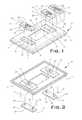
- FIG. 1is a top perspective view of an electrical switch identification plate of the present invention illustrating how indica marking inserts attach to the plate;
- FIG. 2is a bottom perspective view of the electrical switch identification plate illustrating how the indica marking inserts attach to the plate;
- FIG. 3is a top side elevational view of the electrical switch identification plate of the present invention having no indicia marking inserts inserted therein;
- FIG. 4is a cross-sectional view of the electrical switch plate along lines 4 - 4 of FIG. 3;
- FIG. 5is a side elevational view of an indicia marking insert employed with the electrical switch identification plate
- FIG. 6is a bottom plan view of a preferred indicia marking insert employed with the electrical switch identification plate
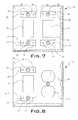
- FIG. 7is a top elevational view of a first alternate embodiment of the electrical switch identification plate of the present invention having no indicia marking inserts inserted therein;
- FIG. 8is a top elevational view of a second alternate embodiment of the electrical switch identification plate of the present invention having no indicia marking inserts inserted therein;
- FIG. 9is a top elevational view of a third alternate embodiment of the electrical switch identification plate of the present invention having indicia marking inserts inserted therein;
- FIG. 10is a fourth alternate embodiment of the electrical switch identification plate of the present invention which is employed with an electrical breaker panel.
- FIG. 11is a side elevational view of a first alternate embodiment of an indicia marking insert employed with the electrical switch identification plate of the present invention which includes a light source for illuminating the indicia marking device when inserted within electrical switch identification plate.
- Plate 10 of FIG. 1represents the preferred embodiment for the subject invention.
- Plate 10has a generally rectangular shape with beveled edges 12 surrounding its outer peripheral such that its side edges are longer in length then its top and bottom edge when vertically employed.
- a rectangular shaped opening 14is formed in a center section 16 of plate 10 and surrounds a rocker style light switch (not shown).
- Formed above and below opening 14are a pair of horizontally disposed rectangular shaped cavities 18 .
- the shape of the cavity and insertscan be, but are not limited to, oval, circular, square and other known shapes.
- Each cavity 18is provided with screw hole 20 formed through at a center portion for mounting plate 10 to a wall. The position of each screw hole 20 is placed such that plate 10 can be used with any standard rocker style switch attached to an electrical scheme.
- Inserts 22can be inserted into cavities 18 .
- Inserts 22have a generally rectangular shape that correspond to the shape of cavities 18 .
- Inserts 22have beveled edges 24 which surround at outer peripheral of each insert 22 .
- a small notch 26is formed along a bottom edge of each insert for permitting the insert to be “popped” out of plate 10 when desired by the use of a small flat bladed screw driver, for example.
- Formed on opposed sides of each screw hole 20are bores 34 for receiving reciprocal pins 36 (see FIG. 2) positioned along insert bottom side 30 .
- Each inserthas a top side 28 (see FIG. 1) and the bottom side 30 (see FIG. 2).
- Indicia 32can be stenciled, or affixed in a bevy of different manners, upon insert top side 28 depending on what the user wants to identify.
- examplesinclude the words light, kitchen, living room, disposal, hall, outside, bedroom, game room, family room, porch, garage, laundry, stairs, chandelier, TV, stereo, computer, lamp, closet, fan, fan light, bathroom, den, desk light, phone, on, and off.
- these wordscould also be substituted for words marked using brail for those who are visually impaired.
- pins 36are positioned at a perpendicular angle to insert bottom side 30 and insert within bores 34 thereby retaining insert 22 within cavity 18 by a friction fit.
- pins 36 of insert 22include a flange member 38 along a tip portion 40 thereby assisting in retaining insert 22 within cavity 18 .
- pins 36are not employed and insert 22 is retained in cavity 18 by friction along its peripheral edges.
- FIGS. 1 - 3 , and 7 - 9all illustrate plates used with the subject invention with an opening 14 which accommodates a rocker style switch, nothing herein limits the use of the subject invention with a pole style switch. In such embodiments, which are not shown in the figures, the opening is significantly smaller to accommodate the pole switch.
- FIG. 7illustrates a first alternate electrical switch plate 40 wherein a pair of openings 14 are employed to surround a pair of switches grouped in close proximity to one another.
- FIG. 8illustrates a second alternate electrical switch plate 42 wherein a single opening 14 is employed for surrounding a single switch mounted in close proximity to an AC outlet.
- second alternate plate 42employs a pair of AC outlet openings 44 formed in plate 42 in a parallel relationship to opening 14 .
- openings 14 and AC outlet openings 44such as, for example, a pair of openings 14 and one set of AC outlet openings.
- third alternate electrical switch plate 46is shown wherein, disposed above opening 14 , are a pair of cavities 18 (not shown) for receiving and retaining a pair of inserts 22 . This is in addition to the insert 22 inserted below opening 14 .
- third alternate platecan include an identifying insert 22 for the switch purpose (i.e., a fan), as well as indicating which position is the “on” position and which position is the “off” position.
- FIG. 10a fourth alternate embodiment is shown.
- a breaker panel plate 48is employed over a breaker panel box 50 .
- Each breaker 52can then be identified by utilizing inserts 22 in the same manner as the preferred and other alternate embodiments described hereinabove.
- an alternate insert 54is shown wherein an LED 56 is employed for illuminating insert 54 .
- LED 56receives its power from the AC electrical lines of the electrical power scheme of the building in which the plate and insert 54 is employed.
- plates which identify computer network related devices and connection devicescan be employed. More particularly, a plate could identify a computer work station network connection (i.e., comp1, comp2, comp3, etc. . . . ). Further, an intranet or internet connection location could be identified (i.e., DSL, cable, satellite, phone, CAT5, etc. . . . ).
Landscapes
- Engineering & Computer Science (AREA)
- Architecture (AREA)
- Civil Engineering (AREA)
- Structural Engineering (AREA)
- Details Of Indoor Wiring (AREA)
Abstract
Description
- 1. Field of the Invention[0001]
- This invention relates to electrical switch plates. More particularly, it relates to a device, in the form of a small plate, for installing around an electrical switch or breaker panel for identifying the electrical device, outlet or breaker associated therewith.[0002]
- 2. Description of Prior Art[0003]
- In all homes and business, electrical switches and outlets are used extensively throughout the respective structure for supplying a source of AC current to the structure. Further, all employ breaker panels. Of course, it is well known that the AC current supplied to a structure is used to power a multitude of different devices and are spaced through the structure in an electrical scheme typically designed by a general contractor, electrical contractor, or architect.[0004]
- In a home environment, the multitude of different devices includes, but are not limited to, lights, fans, computers, kitchen appliances and random AC outlets throughout the home. In many instances, a plurality of electrical switches are grouped together at one location to control a bevy of different devices and outlets. As stated before, this grouping is most likely designed by the architect, general contractor or electrical contractor. It is not common for someone building a new home to become integrally involved in the designing of the electrical scheme of the new home. Discretion is typically left with the expertise of the architect or contractor. However, upon completion of the home, the new home owner may wish to understand the electrical scheme, insofar as understanding which switches control which outlets and devices (i.e., lights and ceiling fans). The home owner could of course review the electrical blueprints to obtain an understanding of the electrical scheme. However, most people would find that reading such a blueprint to be difficult and essentially useless. It would therefore be useful to have a device or system which permits the home owner to identify which switches control which devices and outlets throughout their home.[0005]
- The problem with not knowing which switches control which devices and outlets is exacerbated when someone buys an existing built home. The new owner does not have the architect, electrical contractor or general contractor at their disposal to explain which switches control which devices and outlets. It would therefore be extremely useful to have a device or system that identifies which switches control which devices and outlets.[0006]
- Various labeling devices are well known in the prior art. Theses device typically employ a ribbon-like material which is capable of being imprinted with a word. The ribbon material is loaded on a spool located within a housing of the labeling device having a keyboard. A user types the word to be printed on the keyboard and then engages a print command which in turn ejects a piece of ribbon material having the word printed thereupon. The ribbon material usually has an adhesive backing which can be used to affix the indicia to a desired location. These labeling devices could of course be used to identify switches and outlets, but have inherent disadvantages. Most noticeable is that the adhesive will loosen over time resulting in the indicia falling from its adhered location. Further, the use of an indicia marking device does not provide an aesthetically pleasing appearance since the ribbon print-outs can vary in look and size. What is needed is a device or system which permits the identification of switches and outlets which is permanent, consistent in look as well as aesthetically pleasing to the end user.[0007]
- Similar problems exist in breaker panel boxes wherein a multitude of breakers are located with little or no identification indicia. Typically, upon installation of the breaker panel, an electrical contractor will “pencil-in” a few identifiers for some of the more critical breakers, such as, for example, the clothes washer and dryer, the dishwasher, the water heater and the AC unit. However, most of the remainder of outlets and devices within the electrical scheme are disregarded. This causes a problem for a new home builder as well as a used home buyer.[0008]
- In a large manufacturing facility, wherein an extensive amount of breaker panels are employed, non-marking of the breakers, or electrical switches and outlets, can cause serious problems. One can easily see that a device or system that properly identifies the breaker panel of a hospital, for example, is almost critical. Improper marking, or non-marking could be life threatening in a hospital environment. Further, in a manufacturing facility, mis-marked or non-marked breaker panels could result in cutting power to a machine which could overload and/or cause injury due to the loss of power.[0009]
- A device or system for identifying switches, power outlets and breaker panel boxes is clearly needed. Such a device would be even more useful if it employed a lighting element to enhance its capabilities to identify the switch, outlet or breaker in a low light situation.[0010]
- I have invented an electrical switch and fuse breaker identification plate having an interchangeable indicia insert member. In the preferred electrical switch embodiment, a rectangular plate has a vertically disposed rectangular-shaped opening formed within the plate in a generally middle portion.[0011]
- The plate fits over an electrical switch, such as those known as rocker panels, and can be affixed to a wall. Disposed above and below the vertically disposed opening are a pair of horizontally disposed rectangular cavities formed therein. Screw holes are provided within the cavities for affixing the plate to the wall in the standard location for switches. A pair of small bores are formed on opposed sides of each screw hole within each cavity. An indicia marking insert has a shape that is substantially identical to that of the horizontally disposed cavities. Positioned on a bottom side are a pair of pins which insert within the bores formed in the cavities which causes the insert to be retained therein. Indicia is stenciled on a top side of the insert and acts to identify the use of the switch. A small notch is formed along a side wall of the insert for permitting the insert to be “popped” out when desired.[0012]
- Alternate embodiments for electrical switches can be used with the present invention to accomplish the same desired result. For example, the switch does not need to be a rocker panel style switch, but could be a traditional pole switch, a potentiometer style switch or other known types of switches as well as other wall plate covers for other uses such as cabling applications. Further, alternate embodiments may include plates that are more generally square-shaped for surrounding a pair of switches grouped closely together. Or, a generally square-shaped plate may surround one switch and one outlet (which typically includes a pair of outlets stacked in a vertical position whereby one is disposed over the other).[0013]
- Yet further, an alternate embodiment for switch plates of the present invention could include a total of three indicia marking inserts so that the switch could be marked for its purpose, for example, a “light”’ and also include indicia for “on” and “off”.[0014]
- Yet still further, a breaker panel plate could be used to surround a set of breakers located within a breaker panel. In such an embodiment, each breaker could be labeled by attaching the proper identification indicia insert.[0015]
- Yet still even further, the indicia marking insert could be illuminated, for example, by an LED to permit a person to see the switch or breaker in low light situations. Other known types of illumination can be used, such as, for example, LCD displays and other filament or gas based lighting devices or chemiluminescence based materials.[0016]
- The invention may be best understood by those having ordinary skill in the art by reference to the following detailed description when considered in conjunction with the accompanying drawings in which:[0017]
- FIG. 1 is a top perspective view of an electrical switch identification plate of the present invention illustrating how indica marking inserts attach to the plate;[0018]
- FIG. 2 is a bottom perspective view of the electrical switch identification plate illustrating how the indica marking inserts attach to the plate;[0019]
- FIG. 3 is a top side elevational view of the electrical switch identification plate of the present invention having no indicia marking inserts inserted therein;[0020]
- FIG. 4 is a cross-sectional view of the electrical switch plate along lines[0021]4-4 of FIG. 3;
- FIG. 5 is a side elevational view of an indicia marking insert employed with the electrical switch identification plate;[0022]
- FIG. 6 is a bottom plan view of a preferred indicia marking insert employed with the electrical switch identification plate;[0023]
- FIG. 7 is a top elevational view of a first alternate embodiment of the electrical switch identification plate of the present invention having no indicia marking inserts inserted therein;[0024]
- FIG. 8 is a top elevational view of a second alternate embodiment of the electrical switch identification plate of the present invention having no indicia marking inserts inserted therein;[0025]
- FIG. 9 is a top elevational view of a third alternate embodiment of the electrical switch identification plate of the present invention having indicia marking inserts inserted therein;[0026]
- FIG. 10 is a fourth alternate embodiment of the electrical switch identification plate of the present invention which is employed with an electrical breaker panel; and[0027]
- FIG. 11 is a side elevational view of a first alternate embodiment of an indicia marking insert employed with the electrical switch identification plate of the present invention which includes a light source for illuminating the indicia marking device when inserted within electrical switch identification plate.[0028]
- Throughout the following detailed description, the same reference numerals refer to the same elements in all figures.[0029]
- Referring to FIG. 1, an electrical[0030]
switch identification plate 10 of the present invention is shown.Plate 10 of FIG. 1 represents the preferred embodiment for the subject invention.Plate 10 has a generally rectangular shape withbeveled edges 12 surrounding its outer peripheral such that its side edges are longer in length then its top and bottom edge when vertically employed. A rectangular shapedopening 14 is formed in acenter section 16 ofplate 10 and surrounds a rocker style light switch (not shown). Formed above and below opening14 are a pair of horizontally disposed rectangular shapedcavities 18. In alternate embodiments, the shape of the cavity and inserts can be, but are not limited to, oval, circular, square and other known shapes. Eachcavity 18 is provided withscrew hole 20 formed through at a center portion for mountingplate 10 to a wall. The position of eachscrew hole 20 is placed such thatplate 10 can be used with any standard rocker style switch attached to an electrical scheme. - With continuing reference to FIG. 1, it is shown[0031]
indicia marking inserts 22 can be inserted intocavities 18.Inserts 22 have a generally rectangular shape that correspond to the shape ofcavities 18.Inserts 22 have bevelededges 24 which surround at outer peripheral of eachinsert 22. Asmall notch 26 is formed along a bottom edge of each insert for permitting the insert to be “popped” out ofplate 10 when desired by the use of a small flat bladed screw driver, for example. Formed on opposed sides of eachscrew hole 20 arebores 34 for receiving reciprocal pins36 (see FIG. 2) positioned alonginsert bottom side 30. - Each insert has a top side[0032]28 (see FIG. 1) and the bottom side30 (see FIG. 2).
Indicia 32 can be stenciled, or affixed in a bevy of different manners, uponinsert top side 28 depending on what the user wants to identify. Although not fully illustrative, examples include the words light, kitchen, living room, disposal, hall, outside, bedroom, game room, family room, porch, garage, laundry, stairs, chandelier, TV, stereo, computer, lamp, closet, fan, fan light, bathroom, den, desk light, phone, on, and off. Although not shown, these words could also be substituted for words marked using brail for those who are visually impaired. - Referring to FIG. 2, it is shown that pins[0033]36 are positioned at a perpendicular angle to insert
bottom side 30 and insert withinbores 34 thereby retaininginsert 22 withincavity 18 by a friction fit. As shown in FIG. 5, pins36 ofinsert 22 include aflange member 38 along atip portion 40 thereby assisting in retaininginsert 22 withincavity 18. In an alternate embodiment, pins36 are not employed and insert22 is retained incavity 18 by friction along its peripheral edges. - Although FIGS.[0034]1-3, and7-9 all illustrate plates used with the subject invention with an
opening 14 which accommodates a rocker style switch, nothing herein limits the use of the subject invention with a pole style switch. In such embodiments, which are not shown in the figures, the opening is significantly smaller to accommodate the pole switch. - Referring to FIGS.[0035]7-10, alternate embodiments of the present invention are shown. FIG. 7 illustrates a first alternate
electrical switch plate 40 wherein a pair ofopenings 14 are employed to surround a pair of switches grouped in close proximity to one another. FIG. 8 illustrates a second alternateelectrical switch plate 42 wherein asingle opening 14 is employed for surrounding a single switch mounted in close proximity to an AC outlet. Accordingly, secondalternate plate 42 employs a pair ofAC outlet openings 44 formed inplate 42 in a parallel relationship toopening 14. Of course, nothing herein limits other combinations ofopenings 14 andAC outlet openings 44, such as, for example, a pair ofopenings 14 and one set of AC outlet openings. - Referring to FIG. 9, a third alternate[0036]
electrical switch plate 46 is shown wherein, disposed above opening14, are a pair of cavities18 (not shown) for receiving and retaining a pair ofinserts 22. This is in addition to theinsert 22 inserted belowopening 14. As illustrated, although not limited herein in any manner by FIG. 9, third alternate plate can include an identifyinginsert 22 for the switch purpose (i.e., a fan), as well as indicating which position is the “on” position and which position is the “off” position. - Referring to FIG. 10, a fourth alternate embodiment is shown. In particular, a[0037]
breaker panel plate 48 is employed over abreaker panel box 50. Eachbreaker 52 can then be identified by utilizinginserts 22 in the same manner as the preferred and other alternate embodiments described hereinabove. - Referring to FIG. 11, an[0038]
alternate insert 54 is shown wherein anLED 56 is employed for illuminatinginsert 54.LED 56 receives its power from the AC electrical lines of the electrical power scheme of the building in which the plate and insert54 is employed. - Although not shown, additional alternate embodiments for the subject invention can be provided. For instance, plates which identify computer network related devices and connection devices can be employed. More particularly, a plate could identify a computer work station network connection (i.e., comp1, comp2, comp3, etc. . . . ). Further, an intranet or internet connection location could be identified (i.e., DSL, cable, satellite, phone, CAT5, etc. . . . ).[0039]
- Equivalent elements can be substituted for the ones set forth above such that they perform the same function in the same way for achieving the same result.[0040]
Claims (20)
1. An identification plate mounted to a substrate comprising:
a) the plate having a generally flat shape, a top and bottom surface and at least one opening formed therein,
b) at least two cavities formed in the plate and disposed proximal to the at least one opening,
c) at least one screw hole formed through the plate for receiving at least one screw and attaching the plate to the substrate,
d) a pair of bores formed in each cavity,
e) at least two removable indicia insert members, each having a top and bottom surface and a pair of pins inserting into the pair of bores formed in each cavity, each pair of pins attached to each insert member bottom surface at a perpendicular angle thereto, and
f) indicia mounted on the top surface of each removable indicia insert member.
2. The identification plate ofclaim 1 , wherein one opening and two cavities are employed, a first cavity disposed above the opening and a second cavity disposed below the opening.
3. The identification plate ofclaim 2 , wherein a pair of screw holes are employed, one each formed through each cavity.
4. The identification plate ofclaim 1 , wherein the plate has four beveled edges.
5. The identification plate ofclaim 2 , wherein the plate is generally rectangular shaped.
6. The identification plate ofclaim 5 , wherein the one opening is formed in the plate at a center portion thereof, the one opening having a generally rectangular shape and is disposed in a vertical position such that vertical side edges of the one opening are longer in length than top and bottom edges of the one opening.
7. The identification plate ofclaim 1 , wherein the plate is generally square shaped.
8. The identification plate ofclaim 7 , wherein a pair of openings are employed, each opening having a generally rectangular shape and disposed in a vertical position such that vertical side edges of each opening are longer in length than respective top and bottom edges thereof, the pair of openings juxtaposed in a parallel spaced relationship to one another.
9. The identification plate ofclaim 8 , wherein two pair of cavities are employed, a first pair of cavities formed above and below a first of the pair openings and a second pair of cavities formed above and below a second of the pair of openings.
10. The identification plate ofclaim 9 , wherein two pair of removable indicia insert members are employed, a first pair of insert members inserted within the first pair of cavities and a second pair of insert members inserted within the second pair of cavities.
11. The identification plate ofclaim 7 , wherein a generally rectangular shaped opening is formed in the plate disposed in a vertical position such that vertical side edges of the generally rectangular shaped opening are longer in length than top and bottom edges thereof, and a pair of generally circular openings are formed in the plate such that a first circular opening is disposed above a second circular opening, the first and second circular openings surrounding a pair of electrical sockets mounted within the substrate, the generally rectangular shaped opening positioned juxtaposed the pair of generally circular shaped openings in a parallel spaced relationship.
12. The identification plate ofclaim 1 , wherein a light means is mounted to each removable indicia insert member on the bottom surface thereof, each insert member being translucent for permitting the light means to illuminate the indicia mounted upon the top surface, the light means coupled to an electrical circuit mounted within the substrate.
13. The identification plate ofclaim 1 , wherein the at least one opening surrounds an electrical switch.
14. The identification plate ofclaim 1 , wherein a plurality of openings are formed in the plate in two columns.
15. The identification plate ofclaim 14 , wherein a plurality of cavities are employed, one each for each opening formed in the plate.
16. The identification plate ofclaim 15 , wherein each opening surrounds an electrical breaker switch.
17. An electrical switch identification plate mounted to a wall comprising:
a) the plate having a generally flat shape, a top and bottom surface and at least one opening formed therein,
b) at least two cavities formed in the plate and disposed above and below the at least one opening,
c) at least one screw hole formed through the plate for receiving at least one screw and attaching the switch plate to the wall,
d) a pair of bores formed in each cavity,
e) at least two removable indicia insert members, each having a top and bottom surface and a pair of pins inserting into the pair of bores formed in each cavity, each pair of pins attached to each insert member bottom surface at a perpendicular angle thereto, and
f) indicia mounted on the top surface of each removable indicia insert member.
18. The identification plate ofclaim 17 , wherein one opening and two cavities are employed, a first cavity disposed above the opening and a second cavity disposed below the opening.
19. The identification plate ofclaim 17 , wherein a pair of openings are employed, each opening having a generally rectangular shape and disposed in a vertical position such that vertical side edges of each opening are longer in length than respective top and bottom edges thereof, the pair of openings juxtaposed in a parallel spaced relationship to one another.
20. The identification plate ofclaim 17 , wherein a generally rectangular shaped opening is formed in the plate disposed in a vertical position such that vertical side edges of the generally rectangular shaped opening are longer in length than top and bottom edges thereof, and a pair of generally circular openings are formed in the plate such that a first circular opening is disposed above a second circular opening, the first and second circular openings surrounding a pair of electrical sockets mounted within the wall, the generally rectangular shaped opening positioned juxtaposed the pair of generally circular shaped openings in a parallel spaced relationship.
Priority Applications (1)
| Application Number | Priority Date | Filing Date | Title |
|---|---|---|---|
| US09/916,055US6593530B2 (en) | 2001-07-26 | 2001-07-26 | Electrical switch identification plate with replaceable insert members |
Applications Claiming Priority (1)
| Application Number | Priority Date | Filing Date | Title |
|---|---|---|---|
| US09/916,055US6593530B2 (en) | 2001-07-26 | 2001-07-26 | Electrical switch identification plate with replaceable insert members |
Publications (2)
| Publication Number | Publication Date |
|---|---|
| US20030019732A1true US20030019732A1 (en) | 2003-01-30 |
| US6593530B2 US6593530B2 (en) | 2003-07-15 |
Family
ID=25436631
Family Applications (1)
| Application Number | Title | Priority Date | Filing Date |
|---|---|---|---|
| US09/916,055Expired - Fee RelatedUS6593530B2 (en) | 2001-07-26 | 2001-07-26 | Electrical switch identification plate with replaceable insert members |
Country Status (1)
| Country | Link |
|---|---|
| US (1) | US6593530B2 (en) |
Cited By (9)
| Publication number | Priority date | Publication date | Assignee | Title |
|---|---|---|---|---|
| EP1848070A1 (en)* | 2006-04-18 | 2007-10-24 | Albrecht Jung GmbH & Co. KG | Electric/electronic installation device |
| US20100022600A1 (en)* | 2006-08-28 | 2010-01-28 | Landreth Gary E | Methods and compositions for treating central nervous system tumors |
| US20110000115A1 (en)* | 2009-07-06 | 2011-01-06 | Tyco Electronics Corporation | Faceplate assembly and label cover |
| WO2011035436A1 (en)* | 2009-09-23 | 2011-03-31 | William James Ekins | Electrical system devices, indicia-bearing bodies, and kits including same |
| CN104024022A (en)* | 2011-12-29 | 2014-09-03 | 英特尔公司 | control Panel |
| US20160268071A1 (en)* | 2015-03-10 | 2016-09-15 | Hubbell Incorporated | Wall plate assemblies for identifying electrical devices |
| USD847608S1 (en)* | 2017-06-20 | 2019-05-07 | Snaprays, Llc | Light switch cover plate |
| US20200059018A1 (en)* | 2018-08-14 | 2020-02-20 | Anthony Cerniglia | System and method for identifying and matching corresponding components in an apparatus |
| US11151906B2 (en)* | 2018-08-14 | 2021-10-19 | Anthony Cerniglia | System and method for identifying and matching corresponding components in an apparatus |
Families Citing this family (64)
| Publication number | Priority date | Publication date | Assignee | Title |
|---|---|---|---|---|
| US6660948B2 (en) | 2001-02-28 | 2003-12-09 | Vip Investments Ltd. | Switch matrix |
| US6718674B2 (en)* | 2002-03-21 | 2004-04-13 | Panduit Corp. | Apparatus and system for identification labeling |
| US7279636B2 (en)* | 2002-06-06 | 2007-10-09 | Leviton Manufacturing Co., Inc. | Multifunction clips and ground/mounting strap for wiring device |
| USRE43156E1 (en) | 2002-06-06 | 2012-02-07 | Leviton Manufacturing Co., Inc. | Receptacle with shaped surface |
| US7250580B2 (en)* | 2002-06-06 | 2007-07-31 | Leviton Manufacturing Co., Inc. | Switch with shaped face |
| US7285723B2 (en)* | 2002-06-06 | 2007-10-23 | Leviton Manufacturing Co., Inc. | Receptacle with shaped surface |
| US7030318B2 (en)* | 2002-06-06 | 2006-04-18 | Leviton Manufacturing Co., Inc. | Alignment plate for wiring device |
| US20030226683A1 (en)* | 2002-06-06 | 2003-12-11 | Anthony Tufano | Robust wiring device cover plate |
| US7247792B2 (en)* | 2002-06-06 | 2007-07-24 | Leviton Manufacturing Co., Ltd. | Wall plate with one opening for one or more wiring devices |
| US7244891B2 (en)* | 2002-06-06 | 2007-07-17 | Leviton Manufacturing Co., Inc. | Shaped wall plate for wiring device |
| US7282642B2 (en)* | 2002-06-06 | 2007-10-16 | Leviton Manufacturing Co., Inc. | Shaped wall plate for wiring device |
| US8011937B2 (en)* | 2002-09-17 | 2011-09-06 | Leviton Manufacturing Co., Inc. | Unitary member with multiple outlets having surge protection circuitry |
| USD516411S1 (en) | 2003-09-03 | 2006-03-07 | Vip Investments, Ltd. | Faceplate |
| USD521849S1 (en) | 2003-09-03 | 2006-05-30 | Vip Investments, Ltd. | Faceplate |
| USD505855S1 (en) | 2003-09-03 | 2005-06-07 | Vip Investments, Ltd. | Faceplate |
| US7755506B1 (en) | 2003-09-03 | 2010-07-13 | Legrand Home Systems, Inc. | Automation and theater control system |
| US7394451B1 (en) | 2003-09-03 | 2008-07-01 | Vantage Controls, Inc. | Backlit display with motion sensor |
| US7307542B1 (en) | 2003-09-03 | 2007-12-11 | Vantage Controls, Inc. | System and method for commissioning addressable lighting systems |
| USD509127S1 (en) | 2003-09-03 | 2005-09-06 | Vip Investments, Ltd. | Faceplate |
| USD503607S1 (en) | 2003-09-03 | 2005-04-05 | Vip Investments, Ltd. | Faceplate |
| DE102005015315B4 (en)* | 2005-04-01 | 2014-06-12 | Sew-Eurodrive Gmbh & Co Kg | Device with two-part housing and nameplate |
| US7778262B2 (en) | 2005-09-07 | 2010-08-17 | Vantage Controls, Inc. | Radio frequency multiple protocol bridge |
| US7586040B1 (en)* | 2005-10-11 | 2009-09-08 | Pass & Seymour, Inc. | Multiple component wall plate |
| US7183487B1 (en)* | 2006-01-31 | 2007-02-27 | Panduit Corp. | Stainless steel faceplates with labels |
| US7862350B2 (en)* | 2007-08-20 | 2011-01-04 | Leviton Manufacturing Company, Inc. | Combination device including a guide light and an electrical component |
| CA123790S (en) | 2007-12-04 | 2009-06-01 | Lutron Electronics Co | Lighting control keypad |
| USD595241S1 (en)* | 2008-01-28 | 2009-06-30 | Panasonic Electric Works Co., Ltd. | Switch |
| USD595672S1 (en)* | 2008-01-28 | 2009-07-07 | Panasonic Electric Works Co., Ltd. | Switch |
| USD634866S1 (en)* | 2008-05-16 | 2011-03-22 | Leviton Manufacturing Co., Inc. | Nightlight for an electrical device |
| USD603985S1 (en)* | 2008-05-16 | 2009-11-10 | Leviton Manufacturing Co., Inc. | Nightlight for an electrical device |
| USD603983S1 (en)* | 2008-05-16 | 2009-11-10 | Leviton Manufacturing Co., Inc. | Nightlight for an electrical device |
| USD603984S1 (en)* | 2008-05-16 | 2009-11-10 | Leviton Manufacturing Co., Inc. | Nightlight for an electrical device |
| USD604873S1 (en)* | 2008-05-16 | 2009-11-24 | Leviton Manufacturing Co., Inc. | Nightlight for an electrical device |
| GB2466470A (en)* | 2008-12-22 | 2010-06-23 | Eaton Electric Ltd | A component for a modular electrical assembly |
| USD626092S1 (en)* | 2010-02-23 | 2010-10-26 | Lutron Electronics Co., Inc. | Tabletop remote control keypad |
| USD631852S1 (en)* | 2010-02-23 | 2011-02-01 | Lutron Electronics Co., Inc. | Tabletop remote control keypad |
| USD638805S1 (en)* | 2010-02-23 | 2011-05-31 | Lutron Electronics Co., Inc. | Remote control keypad |
| USD638375S1 (en)* | 2010-02-23 | 2011-05-24 | Lutron Electronics Co., Inc. | Remote control keypad |
| US8444309B2 (en) | 2010-08-13 | 2013-05-21 | Leviton Manufacturing Company, Inc. | Wiring device with illumination |
| USD674753S1 (en) | 2010-08-13 | 2013-01-22 | Leviton Manufacturing Co., Inc. | Wiring device with illumination |
| US8653364B2 (en)* | 2010-12-10 | 2014-02-18 | Brian Joseph Roban | Frame for graphic images |
| TW201301685A (en)* | 2011-06-27 | 2013-01-01 | Hon Hai Prec Ind Co Ltd | Electrical connector and electronic device using same |
| CN104010864B (en)* | 2011-12-29 | 2016-10-26 | 英特尔公司 | Configurable control panel |
| US9065263B2 (en)* | 2012-05-10 | 2015-06-23 | Justin D Porcano | Multifunctional and configurable wall plates |
| DE102013100987B4 (en)* | 2013-01-31 | 2023-06-29 | Phoenix Contact Gmbh & Co. Kg | connection module |
| USD733068S1 (en) | 2013-03-07 | 2015-06-30 | Christopher Johnson | Power controller labeling apparatus |
| US20140317978A1 (en)* | 2013-04-29 | 2014-10-30 | Kyung Tae Kim | Electric Wiring Device Marking System |
| USD714736S1 (en)* | 2013-08-01 | 2014-10-07 | Lutron Electronics Co., Inc. | Load control keypad |
| USD715231S1 (en)* | 2013-08-01 | 2014-10-14 | Lutron Electronics Co., Inc. | Button for a load control device |
| CA2987406C (en)* | 2015-05-26 | 2022-06-14 | Lutron Electronics Co., Inc. | Control device having an integral reflecting structure for a sensing circuit |
| US20170169963A1 (en)* | 2015-12-15 | 2017-06-15 | John Schlick | Light switch indicator |
| USD799432S1 (en)* | 2016-10-27 | 2017-10-10 | Hunter Fan Company | Wall controller |
| US10923889B2 (en) | 2017-10-17 | 2021-02-16 | Crestron Electronics, Inc. | Ganging a plurality of wall mounted electric devices |
| US10401431B1 (en) | 2018-11-30 | 2019-09-03 | Arthur T. Schmidt, III | Methods of making and using an identification tag system for use with an electrical breaker panel and an electrical outlet |
| US10720737B2 (en) | 2017-12-11 | 2020-07-21 | Arthur T. Schmidt, III | Methods of making and using an identification tag system for use with an electrical breaker panel and an electrical outlet |
| US10325192B1 (en) | 2017-12-11 | 2019-06-18 | Hayden T. Schmidt | Electrical outlet/electrical switch identification system for use with an electrical breaker panel and method of making and using the same |
| US10540528B1 (en) | 2017-12-11 | 2020-01-21 | Trexler Technologies, Inc. | Methods of making and using an identification tag system for use with an electromagnetic energy cable |
| US10943749B2 (en) | 2018-03-15 | 2021-03-09 | Crestron Electronics, Inc. | Wall mounted control device with interchangeable buttons |
| US10998705B2 (en)* | 2018-04-04 | 2021-05-04 | SmartPlate LLC | Smart switch faceplate |
| US10362694B1 (en)* | 2018-04-27 | 2019-07-23 | Nanning Fugui Precision Industrial Co., Ltd. | Electronic device with anti-detachment structure |
| WO2023055977A1 (en)* | 2021-10-01 | 2023-04-06 | Hubbell Incorporated | Identification system for recessed floor fitting |
| WO2023086838A1 (en)* | 2021-11-11 | 2023-05-19 | Preddio Technologies Inc. | Contact identification attachment for electrical connectors |
| US20250166945A1 (en)* | 2022-02-22 | 2025-05-22 | Luemelit Llc | Label access mechanisms for rocker switch |
| US20250219371A1 (en)* | 2022-04-05 | 2025-07-03 | Thomas P. Cox | Electrical switch plate cover with replaceable indicia inserts |
Family Cites Families (13)
| Publication number | Priority date | Publication date | Assignee | Title |
|---|---|---|---|---|
| US1930610A (en)* | 1933-02-20 | 1933-10-17 | Pass & Seymour Inc | Card holder |
| US4004120A (en) | 1975-07-17 | 1977-01-18 | C & K Components, Inc. | Switch bezel with visual indicator |
| US4566185A (en) | 1984-06-04 | 1986-01-28 | Horace Bryan | Device and method for firming-up a plug-socket connection |
| AU645088B2 (en) | 1990-08-10 | 1994-01-06 | Siemon Company, The | Panel yoke |
| US5295869A (en) | 1992-12-18 | 1994-03-22 | The Siemon Company | Electrically balanced connector assembly |
| US5807139A (en) | 1994-11-04 | 1998-09-15 | The Siemon Company | Surface mount multimedia outlet |
| US5620335C1 (en) | 1995-03-17 | 2001-02-06 | Siemon Co | Boot with icon holder |
| US5613874A (en) | 1995-05-05 | 1997-03-25 | Ortronics Inc. | Snap-in designation strip for modular information management oulet |
| US5832641A (en) | 1996-01-22 | 1998-11-10 | Pass & Seymour, Inc. | Wiring device circuit identification |
| US5735708A (en) | 1996-04-03 | 1998-04-07 | Lucent Technologies Inc. | Apparatus and method for displaying information at a wall face plate |
| US5977481A (en)* | 1997-12-05 | 1999-11-02 | The Whitaker Corporation | Faceplate with provision for optional icons |
| US6172301B1 (en)* | 1999-07-14 | 2001-01-09 | Hubbell Incorporated | Receptacle faceplate |
| US6421941B1 (en)* | 2000-06-30 | 2002-07-23 | Adc Telecommunications, Inc. | Designation window |
- 2001
- 2001-07-26USUS09/916,055patent/US6593530B2/ennot_activeExpired - Fee Related
Cited By (14)
| Publication number | Priority date | Publication date | Assignee | Title |
|---|---|---|---|---|
| EP1848070A1 (en)* | 2006-04-18 | 2007-10-24 | Albrecht Jung GmbH & Co. KG | Electric/electronic installation device |
| US20100022600A1 (en)* | 2006-08-28 | 2010-01-28 | Landreth Gary E | Methods and compositions for treating central nervous system tumors |
| TWI508401B (en)* | 2009-07-06 | 2015-11-11 | Tyco Electronics Corp | Faceplate assembly and label cover |
| US20110000115A1 (en)* | 2009-07-06 | 2011-01-06 | Tyco Electronics Corporation | Faceplate assembly and label cover |
| WO2011005296A3 (en)* | 2009-07-06 | 2011-12-01 | Tyco Electronics Corporation | Faceplate assembly and label cover |
| US8230629B2 (en) | 2009-07-06 | 2012-07-31 | Tyco Electronics Corporation | Faceplate assembly and label cover |
| WO2011035436A1 (en)* | 2009-09-23 | 2011-03-31 | William James Ekins | Electrical system devices, indicia-bearing bodies, and kits including same |
| CN104024022A (en)* | 2011-12-29 | 2014-09-03 | 英特尔公司 | control Panel |
| US9302679B2 (en) | 2011-12-29 | 2016-04-05 | Intel Corporation | Control panels |
| US20160268071A1 (en)* | 2015-03-10 | 2016-09-15 | Hubbell Incorporated | Wall plate assemblies for identifying electrical devices |
| USD847608S1 (en)* | 2017-06-20 | 2019-05-07 | Snaprays, Llc | Light switch cover plate |
| US20200059018A1 (en)* | 2018-08-14 | 2020-02-20 | Anthony Cerniglia | System and method for identifying and matching corresponding components in an apparatus |
| US10756460B2 (en)* | 2018-08-14 | 2020-08-25 | Anthony Cerniglia | System and method for identifying and matching corresponding components in an apparatus |
| US11151906B2 (en)* | 2018-08-14 | 2021-10-19 | Anthony Cerniglia | System and method for identifying and matching corresponding components in an apparatus |
Also Published As
| Publication number | Publication date |
|---|---|
| US6593530B2 (en) | 2003-07-15 |
Similar Documents
| Publication | Publication Date | Title |
|---|---|---|
| US6593530B2 (en) | Electrical switch identification plate with replaceable insert members | |
| AU2020244598B2 (en) | Consumer product system | |
| US7036961B2 (en) | Recessed lighting fixture with battery backup | |
| US5727867A (en) | Canopy mounting device for exit signs and the like | |
| US6042248A (en) | LED assembly for illuminated signs | |
| CA2047830C (en) | Exit sign with removable emergency power pack module | |
| US7064269B2 (en) | Quick connect electrical junction box assembly | |
| US10539309B2 (en) | Low voltage LED under cabinet light bar | |
| US6908334B2 (en) | Interlining panel structure for multiple socket | |
| US6290365B1 (en) | Lighting device adapted to be removably positioned at any point along an electrical cord | |
| US5811729A (en) | Light switch cover | |
| US5811730A (en) | Light switch cover | |
| US20030042038A1 (en) | Lighted switch or outlet plate with labeling designation | |
| CA2276350A1 (en) | A demonstration display for lighting controls | |
| JP2008214966A (en) | Decorative board | |
| KR200324418Y1 (en) | The Switch on the Power Cord | |
| JP2001309822A (en) | Table of illuminator detachable model | |
| US7731408B2 (en) | Light source shining through a template on to a base | |
| CN207557839U (en) | Power supply module and electronic computer | |
| AU2007100181B4 (en) | Emergency lighting exit signage | |
| CA2047924C (en) | Canopy mounting device for exit signs and the like | |
| TWM445251U (en) | With night vision illumination switch back plate | |
| JP3075979U (en) | Outlet installation structure | |
| KR200237884Y1 (en) | Compact type free standing power distribution panel | |
| CN2187340Y (en) | Electrical connector |
Legal Events
| Date | Code | Title | Description |
|---|---|---|---|
| FEPP | Fee payment procedure | Free format text:PAT HOLDER CLAIMS SMALL ENTITY STATUS, ENTITY STATUS SET TO SMALL (ORIGINAL EVENT CODE: LTOS); ENTITY STATUS OF PATENT OWNER: SMALL ENTITY | |
| FPAY | Fee payment | Year of fee payment:4 | |
| FPAY | Fee payment | Year of fee payment:8 | |
| REMI | Maintenance fee reminder mailed | ||
| LAPS | Lapse for failure to pay maintenance fees | ||
| STCH | Information on status: patent discontinuation | Free format text:PATENT EXPIRED DUE TO NONPAYMENT OF MAINTENANCE FEES UNDER 37 CFR 1.362 | |
| FP | Lapsed due to failure to pay maintenance fee | Effective date:20150715 |