US20030002055A1 - Method of calibrating the optical system of a laser machine for processing electrical circuit substrates - Google Patents
Method of calibrating the optical system of a laser machine for processing electrical circuit substratesDownload PDFInfo
- Publication number
- US20030002055A1 US20030002055A1US10/121,731US12173102AUS2003002055A1US 20030002055 A1US20030002055 A1US 20030002055A1US 12173102 AUS12173102 AUS 12173102AUS 2003002055 A1US2003002055 A1US 2003002055A1
- Authority
- US
- United States
- Prior art keywords
- correction values
- plane
- sample plate
- positions
- target points
- Prior art date
- Legal status (The legal status is an assumption and is not a legal conclusion. Google has not performed a legal analysis and makes no representation as to the accuracy of the status listed.)
- Granted
Links
- 230000003287optical effectEffects0.000titleclaimsabstractdescription15
- 238000012545processingMethods0.000titleclaimsdescription55
- 238000000034methodMethods0.000titleclaimsdescription21
- 239000000758substrateSubstances0.000titleclaimsdescription5
- 238000012937correctionMethods0.000claimsabstractdescription112
- 230000004913activationEffects0.000claimsabstractdescription12
- 238000003384imaging methodMethods0.000claimsabstractdescription10
- 238000013213extrapolationMethods0.000claimsdescription6
- 230000008685targetingEffects0.000claims4
- 230000002093peripheral effectEffects0.000description5
- 238000005553drillingMethods0.000description3
- 238000011161developmentMethods0.000description2
- 241000226585Antennaria plantaginifoliaSpecies0.000description1
- 230000003213activating effectEffects0.000description1
- 230000008901benefitEffects0.000description1
- 239000011248coating agentSubstances0.000description1
- 238000000576coating methodMethods0.000description1
- 238000010586diagramMethods0.000description1
- 230000000694effectsEffects0.000description1
- 238000005530etchingMethods0.000description1
- 239000011521glassSubstances0.000description1
- 238000005286illuminationMethods0.000description1
- 230000006872improvementEffects0.000description1
- 238000003754machiningMethods0.000description1
- 238000013507mappingMethods0.000description1
- 238000012986modificationMethods0.000description1
- 230000004048modificationEffects0.000description1
- 230000008569processEffects0.000description1
- 229910000679solderInorganic materials0.000description1
Images

Classifications
- H—ELECTRICITY
- H05—ELECTRIC TECHNIQUES NOT OTHERWISE PROVIDED FOR
- H05K—PRINTED CIRCUITS; CASINGS OR CONSTRUCTIONAL DETAILS OF ELECTRIC APPARATUS; MANUFACTURE OF ASSEMBLAGES OF ELECTRICAL COMPONENTS
- H05K3/00—Apparatus or processes for manufacturing printed circuits
- B—PERFORMING OPERATIONS; TRANSPORTING
- B23—MACHINE TOOLS; METAL-WORKING NOT OTHERWISE PROVIDED FOR
- B23K—SOLDERING OR UNSOLDERING; WELDING; CLADDING OR PLATING BY SOLDERING OR WELDING; CUTTING BY APPLYING HEAT LOCALLY, e.g. FLAME CUTTING; WORKING BY LASER BEAM
- B23K26/00—Working by laser beam, e.g. welding, cutting or boring
- B23K26/02—Positioning or observing the workpiece, e.g. with respect to the point of impact; Aligning, aiming or focusing the laser beam
- B23K26/04—Automatically aligning, aiming or focusing the laser beam, e.g. using the back-scattered light
- B—PERFORMING OPERATIONS; TRANSPORTING
- B23—MACHINE TOOLS; METAL-WORKING NOT OTHERWISE PROVIDED FOR
- B23K—SOLDERING OR UNSOLDERING; WELDING; CLADDING OR PLATING BY SOLDERING OR WELDING; CUTTING BY APPLYING HEAT LOCALLY, e.g. FLAME CUTTING; WORKING BY LASER BEAM
- B23K26/00—Working by laser beam, e.g. welding, cutting or boring
- B23K26/02—Positioning or observing the workpiece, e.g. with respect to the point of impact; Aligning, aiming or focusing the laser beam
- B—PERFORMING OPERATIONS; TRANSPORTING
- B23—MACHINE TOOLS; METAL-WORKING NOT OTHERWISE PROVIDED FOR
- B23K—SOLDERING OR UNSOLDERING; WELDING; CLADDING OR PLATING BY SOLDERING OR WELDING; CUTTING BY APPLYING HEAT LOCALLY, e.g. FLAME CUTTING; WORKING BY LASER BEAM
- B23K26/00—Working by laser beam, e.g. welding, cutting or boring
- B23K26/70—Auxiliary operations or equipment
- B23K26/702—Auxiliary equipment
- B23K26/705—Beam measuring device
- H—ELECTRICITY
- H05—ELECTRIC TECHNIQUES NOT OTHERWISE PROVIDED FOR
- H05K—PRINTED CIRCUITS; CASINGS OR CONSTRUCTIONAL DETAILS OF ELECTRIC APPARATUS; MANUFACTURE OF ASSEMBLAGES OF ELECTRICAL COMPONENTS
- H05K3/00—Apparatus or processes for manufacturing printed circuits
- H05K3/0011—Working of insulating substrates or insulating layers
- H05K3/0017—Etching of the substrate by chemical or physical means
- H05K3/0026—Etching of the substrate by chemical or physical means by laser ablation
Definitions
- the inventiongenerally relates to a method of calibrating an optical system of a laser machine for processing electrical circuit substrates.
- itrelates to one in which the laser beam of a laser source is directed at target points of a processing surface via a deflecting unit and an imaging unit, the positions of markings on the processing surface being registered and measured with the aid of a camera.
- One aim of an embodiment of the inventionis to specify a method of calibrating the optical system of a laser machine for processing electrical circuit substrates. This can make it possible to process as large an area as possible with the laser and preferably at the same time, position the laser beam with greatest accuracy in the entire processing area and at different working heights with respect to the focal plane.
- a methodmay have the following steps:
- a first sample plate with a prescribed processing surfaceis arranged in the focal plane of the imaging unit as a first calibrating plane, after that target points prescribed on this sample plate are targeted with the laser beam in a grid covering the processing surface and are provided with markings,
- the positions of the markings of the first sample plateare measured with the aid of the camera and compared with the positions of the prescribed target points, first correction values from the deviations being stored in each case in a first correction table;
- a second sample plate with the prescribed processing surfaceis arranged in a second calibrating plane parallel to and at a prescribed distance from the focal plane, after that the target points on this second sample plate are likewise targeted with the laser beam in the same grid as in the case of the first sample plate and provided with markings,
- the positions of the markings of the second sample plateare likewise measured and compared with the positions of the prescribed target points, second correction values being determined from the deviations and stored in each case in a second correction table, and
- the correction values from the first correction table and the second correction tableare fed to a control unit, which determines as required for each target point in each arbitrary processing plane lying between the focal plane and the second calibrating plane in each case current correction values by interpolation from the first correction values and the second correction values and makes them available for the activation of the deflecting unit.
- a calibrationcan be performed in at least two different planes, that is to say in the two extreme positions for the processing plane. This can involve determining the pincushion/barrel recordings and the angular errors of the telecentric lens in the two planes and practically converting them into a three-dimensional correction table. In this way, not only is a horizontal interpolation of the correction values possible in the two planes measured for the calibration, but any desired processing heights lying in between can also be interpolated. Consequently, a large recording area, for example 50 mm ⁇ 50 mm, can also be used outside the focal plane, the advantage in terms of speed being accompanied by a consistent accuracy during processing.
- the beam of the camerais directed over the same optical path as the laser beam.
- an additional optical errormay be caused by the illumination for the camera image having a different wavelength than the laser beam.
- a pattern plate(mapping plate) with the prescribed target points of corresponding, highly accurately marked grid points is arranged in the focal plane, that then the positions of the grid points are measured with the aid of the camera and that the deviations of the measured positions from the prescribed positions of the grid points are stored in a camera correction table and are taken into account during the determination of the correction values for the activation of the deflecting unit.
- a third sample plate with the prescribed processing surfaceis arranged in a third calibrating plane, parallel to the focal plane and at a prescribed distance from it, but lying opposite from the second calibrating plane with respect to the focal plane,
- the target points on this sample plateare likewise targeted with the laser beam in the same grid as in the case of the first sample plate and the second sample plate and provided with markings,
- the positions of the markings of the third sample plateare measured with the aid of the camera and compared with the positions of the prescribed target points, third correction values being obtained from the deviations and stored in each case in a third correction table, and
- the correction values from the first correction table and the third correction tableare fed to the control unit, which determines as required for each target point in each arbitrary processing plane lying between the focal plane and the third calibrating plane correction values by interpolation from the first correction values and the third correction values and makes them available for the activation of the deflecting unit.
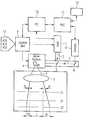
- the single FIGUREshows a schematic representation of the various calibrating planes in conjunction with a block diagram of the laser processing arrangement.
- the figureshows in block representation the main parts of a laser processing machine.
- the centerpieceis a laser source, the laser beam 2 of which is deflected via a dichroic mirror 3 and is fed to a galvanometer-mirror deflecting unit 4 .
- Thishas two mirrors, which are movable about mutually perpendicular axes and with which the beam can be directed to any point of a processing area.
- a telecentric lens 5which focuses the beam into the desired plane, is arranged between the deflecting system 4 and the actual processing area.
- the focal planeis denoted in the present example by Z 1 . Ideally, this would cover an area with the side length L.
- the lens 5increasingly has deflection errors toward its peripheral region and, what is more, the deflecting system 4 is also affected by errors
- the area actually reached by the laser beamis deformed in an approximately pincushion-shaped or barrel-shaped manner, so that, for example, deflecting errors f 1 and f 2 occur beyond the side length L in the peripheral regions of the processing area in the focal plane Z 1 , but in addition to that greater deflecting errors f 3 and f 4 occur in the peripheral regions of the processing surface in a processing plane Z 2 remote from the focal plane.
- These deviationsare also generally not symmetrical, but of different magnitudes to all sides.
- the processing surfaceis measured by means of a camera 6 , which receives a laser beam 7 over the optical path of the laser beam, that is to say via the lens 5 and the deflecting unit 4 and also via the dichroic mirror 3 .
- This beam 7is directed into the camera by means of a further mirror 8 .
- a control unit 9which is generally part of a computer 10 , serves for controlling the laser source 1 and the deflecting unit 4 .
- a stored-program controller 11is provided, which controls both the camera and the robot 12 serving for the movement of the processing surface.
- a pattern plateon which a grid of highly accurately arranged marking points covering the entire machining surface is recorded, is arranged over the focal plane Z 1 .
- These grid pointsare illuminated by means of an illuminating device (not represented), which contains, for example, light-emitting diodes of a wavelength of 800 nm, and is measured with the aid of the camera.
- the obtained coordinates of each individual marking pointare compared with their known position values; deviations are stored in a camera correction table KTK, preferably in a memory 13 of the computer 10 .
- a first sample plateis then arranged in the focal plane Z 1 .
- Thisis, for example, a glass plate provided with a white coating.
- all the grid points of the prescribed processing areaare then targeted as target points with the laser beam and marked, for example by a cross being burned in by the laser beam.
- These markingsare subsequently scanned and measured with the camera 6 , the measured coordinates being compared with the target coordinates of the individual grid points.
- the deviationsare entered in the form of correction values into a first correction table KT 1 in the memory 13 .
- a blank second sample plateis then in turn arranged in a second processing plane Z 2 , which is remote from the focal plane Z 1 by a prescribed amount.
- a second processing plane Z 2which is remote from the focal plane Z 1 by a prescribed amount.
Landscapes
- Engineering & Computer Science (AREA)
- Physics & Mathematics (AREA)
- Optics & Photonics (AREA)
- Plasma & Fusion (AREA)
- Mechanical Engineering (AREA)
- Manufacturing & Machinery (AREA)
- Microelectronics & Electronic Packaging (AREA)
- Laser Beam Processing (AREA)
- Mechanical Optical Scanning Systems (AREA)
Abstract
Description
- This application claims priority under[0001]35 U.S.C. Section 119 on German application number DE 10131610.0, filed on Jun. 29, 2001, the entire contents of which are hereby incorporated herein by reference.
- The invention generally relates to a method of calibrating an optical system of a laser machine for processing electrical circuit substrates. Preferably, it relates to one in which the laser beam of a laser source is directed at target points of a processing surface via a deflecting unit and an imaging unit, the positions of markings on the processing surface being registered and measured with the aid of a camera.[0002]
- For the processing of electrical circuit substrates, for example printed circuit boards, lasers are being increasingly used whenever very fine structures are to be processed at great speed. This concerns, for example, the drilling of through-holes or blind holes for plating-through between various layers of a printed circuit board, the structuring of conducting layers or else non-conducting layers, of solder resists, etching resist layers and the like. In this case, for example, blind holes are drilled in a number of steps, it being possible for the actual processing plane to lie at a different height in relation to the focal plane of the optical system, in order for example to make different energy densities take effect.[0003]
- As long as the laser beam is deflected only over a small processing surface, good positioning accuracy can be achieved, since in this case only the middle part of the telecentric lens necessary for the focusing of the laser beam is used. Since the optical axis of the f-theta lens always conforms well to telecentrics, there are also no problems when drilling or structuring is carried out outside the focal plane.[0004]
- However, the wish to cover a greater processing area, in order to increase the working speed and yield with the laser beam, is increasingly arising, it then also being necessary to use the peripheral regions of the telecentric lens. Since, however, these lenses have an angular error that increases toward the peripheral region, the positioning errors increase all the more the further beam is used away from the optical axis.[0005]
- A certain improvement can be achieved by measuring with the camera a pattern plate with precisely prescribed markings, deriving correction values from this and taking these into account when activating the deflecting system. However, it has been found that such correction values become increasingly inadequate for exact positioning the more the processing plane lies outside the focal plane.[0006]
- One aim of an embodiment of the invention is to specify a method of calibrating the optical system of a laser machine for processing electrical circuit substrates. This can make it possible to process as large an area as possible with the laser and preferably at the same time, position the laser beam with greatest accuracy in the entire processing area and at different working heights with respect to the focal plane.[0007]
- According to an embodiment of the invention, a method may have the following steps:[0008]
- a first sample plate with a prescribed processing surface is arranged in the focal plane of the imaging unit as a first calibrating plane, after that target points prescribed on this sample plate are targeted with the laser beam in a grid covering the processing surface and are provided with markings,[0009]
- the positions of the markings of the first sample plate are measured with the aid of the camera and compared with the positions of the prescribed target points, first correction values from the deviations being stored in each case in a first correction table;[0010]
- a second sample plate with the prescribed processing surface is arranged in a second calibrating plane parallel to and at a prescribed distance from the focal plane, after that the target points on this second sample plate are likewise targeted with the laser beam in the same grid as in the case of the first sample plate and provided with markings,[0011]
- the positions of the markings of the second sample plate are likewise measured and compared with the positions of the prescribed target points, second correction values being determined from the deviations and stored in each case in a second correction table, and[0012]
- the correction values from the first correction table and the second correction table are fed to a control unit, which determines as required for each target point in each arbitrary processing plane lying between the focal plane and the second calibrating plane in each case current correction values by interpolation from the first correction values and the second correction values and makes them available for the activation of the deflecting unit.[0013]
- Consequently, in the method according to an embodiment of the invention, a calibration can be performed in at least two different planes, that is to say in the two extreme positions for the processing plane. This can involve determining the pincushion/barrel recordings and the angular errors of the telecentric lens in the two planes and practically converting them into a three-dimensional correction table. In this way, not only is a horizontal interpolation of the correction values possible in the two planes measured for the calibration, but any desired processing heights lying in between can also be interpolated. Consequently, a large recording area, for example 50 mm×50 mm, can also be used outside the focal plane, the advantage in terms of speed being accompanied by a consistent accuracy during processing.[0014]
- In an advantageous refinement of the laser drilling machine, it is provided in a known way that the beam of the camera is directed over the same optical path as the laser beam. In this case, an additional optical error may be caused by the illumination for the camera image having a different wavelength than the laser beam. In this case, it is provided in a development of the invention that, before the irradiation of the first sample plate, a pattern plate (mapping plate) with the prescribed target points of corresponding, highly accurately marked grid points is arranged in the focal plane, that then the positions of the grid points are measured with the aid of the camera and that the deviations of the measured positions from the prescribed positions of the grid points are stored in a camera correction table and are taken into account during the determination of the correction values for the activation of the deflecting unit.[0015]
- For special cases, it may also be desired to shift the processing plane not only toward one side of the focal plane, but also toward the other side of the focal plane. For this case, the following additional steps may be provided in a development:[0016]
- a third sample plate with the prescribed processing surface is arranged in a third calibrating plane, parallel to the focal plane and at a prescribed distance from it, but lying opposite from the second calibrating plane with respect to the focal plane,[0017]
- after that, the target points on this sample plate are likewise targeted with the laser beam in the same grid as in the case of the first sample plate and the second sample plate and provided with markings,[0018]
- the positions of the markings of the third sample plate are measured with the aid of the camera and compared with the positions of the prescribed target points, third correction values being obtained from the deviations and stored in each case in a third correction table, and[0019]
- the correction values from the first correction table and the third correction table are fed to the control unit, which determines as required for each target point in each arbitrary processing plane lying between the focal plane and the third calibrating plane correction values by interpolation from the first correction values and the third correction values and makes them available for the activation of the deflecting unit.[0020]
- In a further refinement, it is also possible, if required, to use a processing plane beyond the region of the second and possibly third calibrating planes used for the calibration, the correction values from the first correction table and the second and/or third correction tables then also being used to determine correction values by extrapolation for target points outside the region given by the focal plane and the second and/or third calibrating plane.[0021]
- The invention is explained in more detail below on the basis of an exemplary embodiment with reference to the drawing.[0022]
- The single FIGURE shows a schematic representation of the various calibrating planes in conjunction with a block diagram of the laser processing arrangement.[0023]
- The figure shows in block representation the main parts of a laser processing machine. The centerpiece is a laser source, the[0024]
laser beam 2 of which is deflected via adichroic mirror 3 and is fed to a galvanometer-mirror deflecting unit 4. This has two mirrors, which are movable about mutually perpendicular axes and with which the beam can be directed to any point of a processing area. For focusing, atelecentric lens 5, which focuses the beam into the desired plane, is arranged between thedeflecting system 4 and the actual processing area. The focal plane is denoted in the present example by Z1. Ideally, this would cover an area with the side length L. Since, however, thelens 5 increasingly has deflection errors toward its peripheral region and, what is more, thedeflecting system 4 is also affected by errors, the area actually reached by the laser beam is deformed in an approximately pincushion-shaped or barrel-shaped manner, so that, for example, deflecting errors f1 and f2 occur beyond the side length L in the peripheral regions of the processing area in the focal plane Z1, but in addition to that greater deflecting errors f3 and f4 occur in the peripheral regions of the processing surface in a processing plane Z2 remote from the focal plane. These deviations are also generally not symmetrical, but of different magnitudes to all sides. - The processing surface is measured by means of a camera[0025]6, which receives a
laser beam 7 over the optical path of the laser beam, that is to say via thelens 5 and thedeflecting unit 4 and also via thedichroic mirror 3. Thisbeam 7 is directed into the camera by means of afurther mirror 8. Acontrol unit 9, which is generally part of acomputer 10, serves for controlling thelaser source 1 and thedeflecting unit 4. Furthermore, a stored-program controller 11 is provided, which controls both the camera and therobot 12 serving for the movement of the processing surface. - To calibrate the system, firstly a pattern plate, on which a grid of highly accurately arranged marking points covering the entire machining surface is recorded, is arranged over the focal plane Z[0026]1. These grid points are illuminated by means of an illuminating device (not represented), which contains, for example, light-emitting diodes of a wavelength of 800 nm, and is measured with the aid of the camera. The obtained coordinates of each individual marking point are compared with their known position values; deviations are stored in a camera correction table KTK, preferably in a
memory 13 of thecomputer 10. - In the first actual calibrating step for the deflection of the laser beam, a first sample plate is then arranged in the focal plane Z[0027]1. This is, for example, a glass plate provided with a white coating. On this first sample plate, all the grid points of the prescribed processing area are then targeted as target points with the laser beam and marked, for example by a cross being burned in by the laser beam. These markings are subsequently scanned and measured with the camera6, the measured coordinates being compared with the target coordinates of the individual grid points. The deviations are entered in the form of correction values into a first correction table KT1 in the
memory 13. - In a further calibrating step, a blank second sample plate is then in turn arranged in a second processing plane Z[0028]2, which is remote from the focal plane Z1 by a prescribed amount. As in the case of the previous calibrating step, this time again each grid point of the processing area is targeted with the laser beam and burned in in the form of a marking. After that, again all the markings are scanned and measured by the camera6; the deviations from the positional data of the target points are entered as second correction values into a second correction table KT2 in the
memory 13. - With the correction values obtained and stored in this way, a correction value for each target point of an arbitrary plane Zi in the spatial region between the focal plane Z[0029]1 and the second calibrating plane Z2 can be derived by interpolation from the two correction tables KT1 and KT2. Consequently, for example, bores can be positioned with an accuracy of +5 m.
- The invention being thus described, it will be obvious that the same may be varied in many ways. Such variations are not to be regarded as a departure from the spirit and scope of the invention, and all such modifications as would be obvious to one skilled in the art are intended to be included within the scope of the following claims.[0030]
Claims (14)
Applications Claiming Priority (3)
| Application Number | Priority Date | Filing Date | Title |
|---|---|---|---|
| DE10131610 | 2001-06-29 | ||
| DE10131610.0 | 2001-06-29 | ||
| DE10131610ADE10131610C1 (en) | 2001-06-29 | 2001-06-29 | Method for calibrating the optical system of a laser machine for processing electrical circuit substrates |
Publications (2)
| Publication Number | Publication Date |
|---|---|
| US20030002055A1true US20030002055A1 (en) | 2003-01-02 |
| US6678061B2 US6678061B2 (en) | 2004-01-13 |
Family
ID=7690057
Family Applications (1)
| Application Number | Title | Priority Date | Filing Date |
|---|---|---|---|
| US10/121,731Expired - Fee RelatedUS6678061B2 (en) | 2001-06-29 | 2002-04-15 | Method of calibrating the optical system of a laser machine for processing electrical circuit substrates |
Country Status (7)
| Country | Link |
|---|---|
| US (1) | US6678061B2 (en) |
| EP (1) | EP1401609B1 (en) |
| JP (1) | JP2004532740A (en) |
| KR (1) | KR20040045404A (en) |
| CN (1) | CN1246116C (en) |
| DE (2) | DE10131610C1 (en) |
| WO (1) | WO2003004212A1 (en) |
Cited By (35)
| Publication number | Priority date | Publication date | Assignee | Title |
|---|---|---|---|---|
| WO2005016587A1 (en)* | 2003-08-11 | 2005-02-24 | Hitachi Via Mechanics, Ltd. | Method for determining the position of the surface of a workpiece inside a laser machining unit |
| US20090261910A1 (en)* | 2006-04-12 | 2009-10-22 | Nxp B.V. | Method and system for configuration of a phase-locked loop circuit |
| US20090315222A1 (en)* | 2005-11-22 | 2009-12-24 | Andrewlavage Jr Edward Francis | Apparatus, System And Method For Manufacturing A Plugging Mask For A Honeycomb Substrate |
| US20120182376A1 (en)* | 2011-01-19 | 2012-07-19 | Keyence Corporation | Laser Processing Device |
| US20120260512A1 (en)* | 2010-01-20 | 2012-10-18 | Faro Technologies, Inc. | Coordinate measurement machines with removable accessories |
| US20130186871A1 (en)* | 2011-10-21 | 2013-07-25 | Kataoka Corporation | Laser processing machine |
| US8942940B2 (en) | 2010-01-20 | 2015-01-27 | Faro Technologies, Inc. | Portable articulated arm coordinate measuring machine and integrated electronic data processing system |
| US9074883B2 (en) | 2009-03-25 | 2015-07-07 | Faro Technologies, Inc. | Device for optically scanning and measuring an environment |
| US9113023B2 (en) | 2009-11-20 | 2015-08-18 | Faro Technologies, Inc. | Three-dimensional scanner with spectroscopic energy detector |
| US9163922B2 (en) | 2010-01-20 | 2015-10-20 | Faro Technologies, Inc. | Coordinate measurement machine with distance meter and camera to determine dimensions within camera images |
| US9168654B2 (en) | 2010-11-16 | 2015-10-27 | Faro Technologies, Inc. | Coordinate measuring machines with dual layer arm |
| US9210288B2 (en) | 2009-11-20 | 2015-12-08 | Faro Technologies, Inc. | Three-dimensional scanner with dichroic beam splitters to capture a variety of signals |
| CN105328350A (en)* | 2015-10-09 | 2016-02-17 | 江苏大金激光科技有限公司 | Laser cutting head with automatic perforation detection function |
| WO2016026664A1 (en)* | 2014-08-20 | 2016-02-25 | Arcam Ab | Energy beam size verification |
| WO2016026666A1 (en)* | 2014-08-20 | 2016-02-25 | Arcam Ab | Energy beam position verification |
| WO2016026663A1 (en)* | 2014-08-20 | 2016-02-25 | Arcam Ab | Energy beam deflection speed verification |
| US9329271B2 (en) | 2010-05-10 | 2016-05-03 | Faro Technologies, Inc. | Method for optically scanning and measuring an environment |
| US9372265B2 (en) | 2012-10-05 | 2016-06-21 | Faro Technologies, Inc. | Intermediate two-dimensional scanning with a three-dimensional scanner to speed registration |
| EP3045256A1 (en)* | 2014-11-20 | 2016-07-20 | Industrial Technology Research Institute | Three-dimensional laser processing apparatus and positioning error correction method |
| US9417316B2 (en) | 2009-11-20 | 2016-08-16 | Faro Technologies, Inc. | Device for optically scanning and measuring an environment |
| US9417056B2 (en) | 2012-01-25 | 2016-08-16 | Faro Technologies, Inc. | Device for optically scanning and measuring an environment |
| US9513107B2 (en) | 2012-10-05 | 2016-12-06 | Faro Technologies, Inc. | Registration calculation between three-dimensional (3D) scans based on two-dimensional (2D) scan data from a 3D scanner |
| US9529083B2 (en) | 2009-11-20 | 2016-12-27 | Faro Technologies, Inc. | Three-dimensional scanner with enhanced spectroscopic energy detector |
| US9551575B2 (en) | 2009-03-25 | 2017-01-24 | Faro Technologies, Inc. | Laser scanner having a multi-color light source and real-time color receiver |
| US9607239B2 (en) | 2010-01-20 | 2017-03-28 | Faro Technologies, Inc. | Articulated arm coordinate measurement machine having a 2D camera and method of obtaining 3D representations |
| US9628775B2 (en) | 2010-01-20 | 2017-04-18 | Faro Technologies, Inc. | Articulated arm coordinate measurement machine having a 2D camera and method of obtaining 3D representations |
| US9879976B2 (en) | 2010-01-20 | 2018-01-30 | Faro Technologies, Inc. | Articulated arm coordinate measurement machine that uses a 2D camera to determine 3D coordinates of smoothly continuous edge features |
| WO2018086996A1 (en) | 2016-11-11 | 2018-05-17 | Trumpf Laser- Und Systemtechnik Gmbh | Method for calibrating a scanner, and machining device |
| US10067231B2 (en) | 2012-10-05 | 2018-09-04 | Faro Technologies, Inc. | Registration calculation of three-dimensional scanner data performed between scans based on measurements by two-dimensional scanner |
| US10175037B2 (en) | 2015-12-27 | 2019-01-08 | Faro Technologies, Inc. | 3-D measuring device with battery pack |
| WO2019025328A1 (en)* | 2017-08-03 | 2019-02-07 | Trumpf Werkzeugmaschinen Gmbh + Co. Kg | METHOD FOR LASER MATERIAL PROCESSING AND LASER MACHINE |
| EP3815820A1 (en)* | 2019-10-31 | 2021-05-05 | Concept Laser GmbH | Method for calibration of at least one irradiation device of an apparatus for additively manufacturing three-dimensional objects |
| US11110301B2 (en) | 2017-08-21 | 2021-09-07 | Shanghai United Imaging Healthcare Co., Ltd. | Systems and methods for calibrating an alignment device |
| US12128478B2 (en) | 2019-05-17 | 2024-10-29 | Nikon Slm Solutions Ag | Method and apparatus for calibrating optical elements |
| CN119246471A (en)* | 2024-09-30 | 2025-01-03 | 华南师范大学 | A system and method for measuring reflectivity of high-reflectivity materials in optical cavity ring-down |
Families Citing this family (28)
| Publication number | Priority date | Publication date | Assignee | Title |
|---|---|---|---|---|
| US7723642B2 (en) | 1999-12-28 | 2010-05-25 | Gsi Group Corporation | Laser-based system for memory link processing with picosecond lasers |
| US7838794B2 (en) | 1999-12-28 | 2010-11-23 | Gsi Group Corporation | Laser-based method and system for removing one or more target link structures |
| US20060141681A1 (en)* | 2000-01-10 | 2006-06-29 | Yunlong Sun | Processing a memory link with a set of at least two laser pulses |
| US20030222324A1 (en)* | 2000-01-10 | 2003-12-04 | Yunlong Sun | Laser systems for passivation or link processing with a set of laser pulses |
| US7671295B2 (en)* | 2000-01-10 | 2010-03-02 | Electro Scientific Industries, Inc. | Processing a memory link with a set of at least two laser pulses |
| US20030024913A1 (en)* | 2002-04-15 | 2003-02-06 | Downes Joseph P. | Laser scanning method and system for marking articles such as printed circuit boards, integrated circuits and the like |
| DE10206183A1 (en)* | 2002-02-14 | 2003-08-28 | Siemens Ag | Process for determining the accuracy of machine tools |
| US7015418B2 (en) | 2002-05-17 | 2006-03-21 | Gsi Group Corporation | Method and system for calibrating a laser processing system and laser marking system utilizing same |
| KR100486088B1 (en)* | 2002-08-21 | 2005-04-29 | 주식회사 이오테크닉스 | Calibrating method of marking for lazer marking system using post vision camera |
| DE10317322B4 (en)* | 2003-04-15 | 2007-01-25 | Lasertec Gmbh | Method and device for determining the removal rate of a laser beam and for producing a die in a workpiece |
| JP2005028423A (en)* | 2003-07-09 | 2005-02-03 | Disco Abrasive Syst Ltd | Laser processing method and laser processing apparatus |
| EP1766326B1 (en)* | 2004-03-19 | 2009-04-29 | JRB Engineering Pty Ltd | Optical method of determining a dimension or orientation of a moving object |
| US7265082B2 (en)* | 2004-08-04 | 2007-09-04 | Honeywell International Inc. | Azeotrope-like compositions of 1,1,1,3,3-pentachloropropane and carbon tetrachloride |
| US20060191884A1 (en)* | 2005-01-21 | 2006-08-31 | Johnson Shepard D | High-speed, precise, laser-based material processing method and system |
| EP1750891B1 (en) | 2005-06-23 | 2007-10-24 | Trumpf Werkzeugmaschinen GmbH + Co. KG | Method for determining the focal position of a laser beam |
| DE102007025463A1 (en)* | 2007-09-09 | 2009-03-12 | Atn Automatisierungstechnik Niemeier Gmbh | Method for processing material with laser having scanner mirrors by temperature sensor coupled in the beam path, comprises correcting the optical distortion between radiation source and sensor depending on the deflection of the mirrors |
| CN101504491B (en)* | 2008-02-05 | 2012-04-11 | 中茂电子(深圳)有限公司 | Optical contraposition apparatus for joint of circuit apparatus and substrates, and system having the same |
| DE102008027891A1 (en)* | 2008-03-12 | 2009-04-23 | Rofin Sinar Laser Gmbh | Laser machine for simultaneously working on several workpieces using separate laser beams has galvoheads which deflect beams outwards, beams then passing through focusing system which focuses them on working plane |
| CN101733561B (en)* | 2009-11-04 | 2012-04-11 | 中国科学院长春光学精密机械与物理研究所 | Method for quickly and precisely adjusting focal plane in laser trimming membrane resistance |
| CN102248817B (en)* | 2010-05-21 | 2013-07-03 | 深圳泰德激光科技有限公司 | Correction method and correction apparatus for laser marking and laser marking system |
| JP6030299B2 (en)* | 2011-12-20 | 2016-11-24 | 株式会社ディスコ | Laser processing equipment |
| TWI555599B (en)* | 2013-02-25 | 2016-11-01 | 先進科技新加坡有限公司 | Method for performing beam characterization in a laser scribe device, and laser scribe device capable of performing the same |
| US10262429B2 (en)* | 2013-09-30 | 2019-04-16 | National Institute Of Advanced Industrial Science | Marker image processing system |
| US9766473B1 (en) | 2014-02-03 | 2017-09-19 | Automation Engineering, Inc. | Automated UV calibration, motorized optical target and automatic surface finder for optical alignment and assembly robot |
| CN105642894B (en)* | 2015-10-14 | 2018-09-07 | 哈尔滨福沃德多维智能装备有限公司 | Galvanometer controls laser scanning accuracy correcting method |
| US10667949B2 (en) | 2015-10-21 | 2020-06-02 | Amo Development, Llc | Laser beam calibration and beam quality measurement in laser surgery systems |
| US10919111B2 (en) | 2018-12-05 | 2021-02-16 | Robert Bosch Tool Corporation | Laser engraver mirror adjustment system |
| US11733187B2 (en) | 2021-02-12 | 2023-08-22 | Arcam Ab | Verification plates with automated evaluation of melt performance |
Citations (7)
| Publication number | Priority date | Publication date | Assignee | Title |
|---|---|---|---|---|
| US4682894A (en)* | 1985-03-21 | 1987-07-28 | Robotic Vision Systems, Inc. | Calibration of three-dimensional space |
| US5530548A (en)* | 1994-11-07 | 1996-06-25 | Automotive Systems Laboratory, Inc. | Calibratable optical distance sensing system and method |
| US5557410A (en)* | 1994-05-26 | 1996-09-17 | Lockheed Missiles & Space Company, Inc. | Method of calibrating a three-dimensional optical measurement system |
| US5663795A (en)* | 1995-09-07 | 1997-09-02 | Virtek Vision Corp. | Method of calibrating laser positions relative to workpieces |
| US5772656A (en)* | 1993-06-04 | 1998-06-30 | Summit Technology, Inc. | Calibration apparatus for laser ablative systems |
| US5867261A (en)* | 1997-04-28 | 1999-02-02 | International Business Machines Corporation | Surface inspection tool |
| US6101455A (en)* | 1998-05-14 | 2000-08-08 | Davis; Michael S. | Automatic calibration of cameras and structured light sources |
Family Cites Families (2)
| Publication number | Priority date | Publication date | Assignee | Title |
|---|---|---|---|---|
| DE4437284A1 (en)* | 1994-10-18 | 1996-04-25 | Eos Electro Optical Syst | Method for calibrating a controller to deflect a laser beam |
| DE19831340C1 (en)* | 1998-07-13 | 2000-03-02 | Siemens Ag | Method and arrangement for calibrating a laser processing machine for processing workpieces |
- 2001
- 2001-06-29DEDE10131610Apatent/DE10131610C1/ennot_activeExpired - Fee Related
- 2002
- 2002-04-15USUS10/121,731patent/US6678061B2/ennot_activeExpired - Fee Related
- 2002-05-27WOPCT/DE2002/001950patent/WO2003004212A1/enactiveIP Right Grant
- 2002-05-27CNCNB028130383Apatent/CN1246116C/ennot_activeExpired - Fee Related
- 2002-05-27KRKR10-2003-7016862Apatent/KR20040045404A/ennot_activeCeased
- 2002-05-27JPJP2003510213Apatent/JP2004532740A/enactivePending
- 2002-05-27EPEP02740382Apatent/EP1401609B1/ennot_activeExpired - Lifetime
- 2002-05-27DEDE50202123Tpatent/DE50202123D1/ennot_activeExpired - Fee Related
Patent Citations (7)
| Publication number | Priority date | Publication date | Assignee | Title |
|---|---|---|---|---|
| US4682894A (en)* | 1985-03-21 | 1987-07-28 | Robotic Vision Systems, Inc. | Calibration of three-dimensional space |
| US5772656A (en)* | 1993-06-04 | 1998-06-30 | Summit Technology, Inc. | Calibration apparatus for laser ablative systems |
| US5557410A (en)* | 1994-05-26 | 1996-09-17 | Lockheed Missiles & Space Company, Inc. | Method of calibrating a three-dimensional optical measurement system |
| US5530548A (en)* | 1994-11-07 | 1996-06-25 | Automotive Systems Laboratory, Inc. | Calibratable optical distance sensing system and method |
| US5663795A (en)* | 1995-09-07 | 1997-09-02 | Virtek Vision Corp. | Method of calibrating laser positions relative to workpieces |
| US5867261A (en)* | 1997-04-28 | 1999-02-02 | International Business Machines Corporation | Surface inspection tool |
| US6101455A (en)* | 1998-05-14 | 2000-08-08 | Davis; Michael S. | Automatic calibration of cameras and structured light sources |
Cited By (53)
| Publication number | Priority date | Publication date | Assignee | Title |
|---|---|---|---|---|
| WO2005016587A1 (en)* | 2003-08-11 | 2005-02-24 | Hitachi Via Mechanics, Ltd. | Method for determining the position of the surface of a workpiece inside a laser machining unit |
| US20090315222A1 (en)* | 2005-11-22 | 2009-12-24 | Andrewlavage Jr Edward Francis | Apparatus, System And Method For Manufacturing A Plugging Mask For A Honeycomb Substrate |
| US20090261910A1 (en)* | 2006-04-12 | 2009-10-22 | Nxp B.V. | Method and system for configuration of a phase-locked loop circuit |
| US8174327B2 (en) | 2006-04-12 | 2012-05-08 | Nxp B.V. | Method and system for configuration of a phase-locked loop circuit |
| US9551575B2 (en) | 2009-03-25 | 2017-01-24 | Faro Technologies, Inc. | Laser scanner having a multi-color light source and real-time color receiver |
| US9074883B2 (en) | 2009-03-25 | 2015-07-07 | Faro Technologies, Inc. | Device for optically scanning and measuring an environment |
| US9113023B2 (en) | 2009-11-20 | 2015-08-18 | Faro Technologies, Inc. | Three-dimensional scanner with spectroscopic energy detector |
| US9529083B2 (en) | 2009-11-20 | 2016-12-27 | Faro Technologies, Inc. | Three-dimensional scanner with enhanced spectroscopic energy detector |
| US9417316B2 (en) | 2009-11-20 | 2016-08-16 | Faro Technologies, Inc. | Device for optically scanning and measuring an environment |
| US9210288B2 (en) | 2009-11-20 | 2015-12-08 | Faro Technologies, Inc. | Three-dimensional scanner with dichroic beam splitters to capture a variety of signals |
| US20120260512A1 (en)* | 2010-01-20 | 2012-10-18 | Faro Technologies, Inc. | Coordinate measurement machines with removable accessories |
| US9163922B2 (en) | 2010-01-20 | 2015-10-20 | Faro Technologies, Inc. | Coordinate measurement machine with distance meter and camera to determine dimensions within camera images |
| US8942940B2 (en) | 2010-01-20 | 2015-01-27 | Faro Technologies, Inc. | Portable articulated arm coordinate measuring machine and integrated electronic data processing system |
| US8875409B2 (en)* | 2010-01-20 | 2014-11-04 | Faro Technologies, Inc. | Coordinate measurement machines with removable accessories |
| US9879976B2 (en) | 2010-01-20 | 2018-01-30 | Faro Technologies, Inc. | Articulated arm coordinate measurement machine that uses a 2D camera to determine 3D coordinates of smoothly continuous edge features |
| US9628775B2 (en) | 2010-01-20 | 2017-04-18 | Faro Technologies, Inc. | Articulated arm coordinate measurement machine having a 2D camera and method of obtaining 3D representations |
| US9607239B2 (en) | 2010-01-20 | 2017-03-28 | Faro Technologies, Inc. | Articulated arm coordinate measurement machine having a 2D camera and method of obtaining 3D representations |
| US10060722B2 (en) | 2010-01-20 | 2018-08-28 | Faro Technologies, Inc. | Articulated arm coordinate measurement machine having a 2D camera and method of obtaining 3D representations |
| US10281259B2 (en) | 2010-01-20 | 2019-05-07 | Faro Technologies, Inc. | Articulated arm coordinate measurement machine that uses a 2D camera to determine 3D coordinates of smoothly continuous edge features |
| US9684078B2 (en) | 2010-05-10 | 2017-06-20 | Faro Technologies, Inc. | Method for optically scanning and measuring an environment |
| US9329271B2 (en) | 2010-05-10 | 2016-05-03 | Faro Technologies, Inc. | Method for optically scanning and measuring an environment |
| US9168654B2 (en) | 2010-11-16 | 2015-10-27 | Faro Technologies, Inc. | Coordinate measuring machines with dual layer arm |
| US20120182376A1 (en)* | 2011-01-19 | 2012-07-19 | Keyence Corporation | Laser Processing Device |
| US9492889B2 (en)* | 2011-10-21 | 2016-11-15 | Kataoka Corporation | Laser processing machine |
| US20130186871A1 (en)* | 2011-10-21 | 2013-07-25 | Kataoka Corporation | Laser processing machine |
| US9417056B2 (en) | 2012-01-25 | 2016-08-16 | Faro Technologies, Inc. | Device for optically scanning and measuring an environment |
| US9618620B2 (en) | 2012-10-05 | 2017-04-11 | Faro Technologies, Inc. | Using depth-camera images to speed registration of three-dimensional scans |
| US11112501B2 (en) | 2012-10-05 | 2021-09-07 | Faro Technologies, Inc. | Using a two-dimensional scanner to speed registration of three-dimensional scan data |
| US10203413B2 (en) | 2012-10-05 | 2019-02-12 | Faro Technologies, Inc. | Using a two-dimensional scanner to speed registration of three-dimensional scan data |
| US9372265B2 (en) | 2012-10-05 | 2016-06-21 | Faro Technologies, Inc. | Intermediate two-dimensional scanning with a three-dimensional scanner to speed registration |
| US11035955B2 (en) | 2012-10-05 | 2021-06-15 | Faro Technologies, Inc. | Registration calculation of three-dimensional scanner data performed between scans based on measurements by two-dimensional scanner |
| US9739886B2 (en) | 2012-10-05 | 2017-08-22 | Faro Technologies, Inc. | Using a two-dimensional scanner to speed registration of three-dimensional scan data |
| US9746559B2 (en) | 2012-10-05 | 2017-08-29 | Faro Technologies, Inc. | Using two-dimensional camera images to speed registration of three-dimensional scans |
| US10739458B2 (en) | 2012-10-05 | 2020-08-11 | Faro Technologies, Inc. | Using two-dimensional camera images to speed registration of three-dimensional scans |
| US11815600B2 (en) | 2012-10-05 | 2023-11-14 | Faro Technologies, Inc. | Using a two-dimensional scanner to speed registration of three-dimensional scan data |
| US9513107B2 (en) | 2012-10-05 | 2016-12-06 | Faro Technologies, Inc. | Registration calculation between three-dimensional (3D) scans based on two-dimensional (2D) scan data from a 3D scanner |
| US10067231B2 (en) | 2012-10-05 | 2018-09-04 | Faro Technologies, Inc. | Registration calculation of three-dimensional scanner data performed between scans based on measurements by two-dimensional scanner |
| WO2016026666A1 (en)* | 2014-08-20 | 2016-02-25 | Arcam Ab | Energy beam position verification |
| WO2016026663A1 (en)* | 2014-08-20 | 2016-02-25 | Arcam Ab | Energy beam deflection speed verification |
| WO2016026664A1 (en)* | 2014-08-20 | 2016-02-25 | Arcam Ab | Energy beam size verification |
| EP3045256A1 (en)* | 2014-11-20 | 2016-07-20 | Industrial Technology Research Institute | Three-dimensional laser processing apparatus and positioning error correction method |
| CN105328350A (en)* | 2015-10-09 | 2016-02-17 | 江苏大金激光科技有限公司 | Laser cutting head with automatic perforation detection function |
| US10175037B2 (en) | 2015-12-27 | 2019-01-08 | Faro Technologies, Inc. | 3-D measuring device with battery pack |
| WO2018086996A1 (en) | 2016-11-11 | 2018-05-17 | Trumpf Laser- Und Systemtechnik Gmbh | Method for calibrating a scanner, and machining device |
| US11899421B2 (en) | 2016-11-11 | 2024-02-13 | Trumpf Laser- Und Systemtechnik Gmbh | Calibrating a scanner device |
| US20200156184A1 (en)* | 2017-08-03 | 2020-05-21 | Trumpf Werkzeugmaschinen Gmbh + Co. Kg | Laser-beam material machining |
| US11612954B2 (en)* | 2017-08-03 | 2023-03-28 | TRUMPF Werkzeugmaschinen SE + Co. KG | Laser-beam material machining |
| WO2019025328A1 (en)* | 2017-08-03 | 2019-02-07 | Trumpf Werkzeugmaschinen Gmbh + Co. Kg | METHOD FOR LASER MATERIAL PROCESSING AND LASER MACHINE |
| US11110301B2 (en) | 2017-08-21 | 2021-09-07 | Shanghai United Imaging Healthcare Co., Ltd. | Systems and methods for calibrating an alignment device |
| US11400317B2 (en)* | 2017-08-21 | 2022-08-02 | Shanghai United Imaging Healthcare Co., Ltd. | Systems and methods for calibrating an alignment device |
| US12128478B2 (en) | 2019-05-17 | 2024-10-29 | Nikon Slm Solutions Ag | Method and apparatus for calibrating optical elements |
| EP3815820A1 (en)* | 2019-10-31 | 2021-05-05 | Concept Laser GmbH | Method for calibration of at least one irradiation device of an apparatus for additively manufacturing three-dimensional objects |
| CN119246471A (en)* | 2024-09-30 | 2025-01-03 | 华南师范大学 | A system and method for measuring reflectivity of high-reflectivity materials in optical cavity ring-down |
Also Published As
| Publication number | Publication date |
|---|---|
| CN1246116C (en) | 2006-03-22 |
| DE50202123D1 (en) | 2005-03-03 |
| KR20040045404A (en) | 2004-06-01 |
| EP1401609B1 (en) | 2005-01-26 |
| WO2003004212A1 (en) | 2003-01-16 |
| DE10131610C1 (en) | 2003-02-20 |
| US6678061B2 (en) | 2004-01-13 |
| EP1401609A1 (en) | 2004-03-31 |
| CN1522187A (en) | 2004-08-18 |
| JP2004532740A (en) | 2004-10-28 |
Similar Documents
| Publication | Publication Date | Title |
|---|---|---|
| US6678061B2 (en) | Method of calibrating the optical system of a laser machine for processing electrical circuit substrates | |
| CN100479968C (en) | Laser beam positioning device for laser machining apparatus | |
| KR101698269B1 (en) | Laser processing machine and calibration method for laser processing machine according to distortion of workpiece | |
| JP5288987B2 (en) | Laser processing equipment | |
| JP3605359B2 (en) | METHOD AND APPARATUS FOR CALIBRATION OF LASER PROCESSING MACHINE FOR PROCESSING WORKING MATERIAL | |
| KR20030014217A (en) | Machining device and machining method | |
| US7181089B2 (en) | Method and apparatus for searching for fiducial marks, and method of detecting positions of the fiducial marks | |
| KR102127109B1 (en) | Substrate measuring device and laser processing system | |
| JP6793892B1 (en) | Laser processing method and laser processing equipment | |
| US6658313B1 (en) | Apparatus for adjusting the origins of module heads of a surface mounting apparatus and method therefor | |
| US6683684B1 (en) | Device for measuring relative position error | |
| JP4091494B2 (en) | Laser machining apparatus and machining position deviation correction method thereof | |
| JP4048873B2 (en) | Positioning method | |
| JP2003220483A (en) | Laser beam machining device and deviation correction method for use therein | |
| JP2010274267A (en) | Laser processing machine | |
| JP3419870B2 (en) | Calibration method of optical system for recognition of visual recognition device and visual recognition device using the method | |
| KR20160107992A (en) | Laser Marking Apparatus | |
| JP3209078B2 (en) | Laser processing equipment | |
| JP2664424B2 (en) | Laser processing machine | |
| KR101937212B1 (en) | A Laser Marking Apparatus Having a Structure of Detecting a Focus Length and a Method for Adjusting the Focus Length Automatically and Detecting a Marking Defect | |
| JP7283982B2 (en) | LASER PROCESSING APPARATUS AND LASER PROCESSING METHOD | |
| JP7451049B2 (en) | Laser processing equipment and laser processing method | |
| US20250303496A1 (en) | Laser processing apparatus | |
| JP2708184B2 (en) | Laser processing machine | |
| JPS6356380A (en) | Laser beam processing machine |
Legal Events
| Date | Code | Title | Description |
|---|---|---|---|
| AS | Assignment | Owner name:SIEMENS AKTIENGESELLSCHAFT, GERMANY Free format text:ASSIGNMENT OF ASSIGNORS INTEREST;ASSIGNORS:KILTHAU, ALEXANDER;KLETTI, ANDRE;MAYER, HANS JUERGEN;AND OTHERS;REEL/FRAME:012945/0075;SIGNING DATES FROM 20020411 TO 20020426 | |
| AS | Assignment | Owner name:HITACHI VIA MECHANICS, LTD., JAPAN Free format text:ASSIGNMENT OF ASSIGNORS INTEREST;ASSIGNOR:SIEMENS AKTIENGESELLSCHAFT;REEL/FRAME:017198/0048 Effective date:20050816 | |
| AS | Assignment | Owner name:HITACHI VIA MECHANICS, LTD., JAPAN Free format text:ASSIGNMENT OF ASSIGNORS INTEREST;ASSIGNOR:SIEMENS AKTIENGESELLSCHAFT;REEL/FRAME:017666/0270 Effective date:20050816 | |
| FEPP | Fee payment procedure | Free format text:PAYOR NUMBER ASSIGNED (ORIGINAL EVENT CODE: ASPN); ENTITY STATUS OF PATENT OWNER: LARGE ENTITY Free format text:PAYER NUMBER DE-ASSIGNED (ORIGINAL EVENT CODE: RMPN); ENTITY STATUS OF PATENT OWNER: LARGE ENTITY | |
| FPAY | Fee payment | Year of fee payment:4 | |
| REMI | Maintenance fee reminder mailed | ||
| LAPS | Lapse for failure to pay maintenance fees | ||
| STCH | Information on status: patent discontinuation | Free format text:PATENT EXPIRED DUE TO NONPAYMENT OF MAINTENANCE FEES UNDER 37 CFR 1.362 | |
| FP | Lapsed due to failure to pay maintenance fee | Effective date:20120113 |