US20030000355A1 - Tools with orientation detection - Google Patents
Tools with orientation detectionDownload PDFInfo
- Publication number
- US20030000355A1 US20030000355A1US10/081,865US8186502AUS2003000355A1US 20030000355 A1US20030000355 A1US 20030000355A1US 8186502 AUS8186502 AUS 8186502AUS 2003000355 A1US2003000355 A1US 2003000355A1
- Authority
- US
- United States
- Prior art keywords
- tool
- guide
- component
- action component
- orientation information
- Prior art date
- Legal status (The legal status is an assumption and is not a legal conclusion. Google has not performed a legal analysis and makes no representation as to the accuracy of the status listed.)
- Granted
Links
- 238000001514detection methodMethods0.000titledescription5
- 230000009471actionEffects0.000claimsabstractdescription117
- 238000005520cutting processMethods0.000claimsabstractdescription25
- 230000007246mechanismEffects0.000claimsdescription54
- 238000010304firingMethods0.000claimsdescription44
- 238000004891communicationMethods0.000claimsdescription43
- 230000004044responseEffects0.000claimsdescription32
- 238000006073displacement reactionMethods0.000claimsdescription27
- 238000000034methodMethods0.000claimsdescription23
- 238000003860storageMethods0.000claimsdescription16
- 230000008859changeEffects0.000claimsdescription2
- 230000015654memoryEffects0.000description17
- 230000003287optical effectEffects0.000description17
- 230000008569processEffects0.000description10
- 238000010586diagramMethods0.000description9
- 238000013461designMethods0.000description6
- 238000012545processingMethods0.000description6
- 230000002093peripheral effectEffects0.000description5
- 238000005096rolling processMethods0.000description5
- 238000005259measurementMethods0.000description3
- 230000011664signalingEffects0.000description3
- 230000008901benefitEffects0.000description2
- 238000012937correctionMethods0.000description2
- 230000006870functionEffects0.000description2
- 238000012986modificationMethods0.000description2
- 230000004048modificationEffects0.000description2
- 239000002023woodSubstances0.000description2
- 238000003491arrayMethods0.000description1
- 238000013479data entryMethods0.000description1
- 238000013500data storageMethods0.000description1
- 238000005553drillingMethods0.000description1
- 230000009977dual effectEffects0.000description1
- 230000003116impacting effectEffects0.000description1
- 239000004973liquid crystal related substanceSubstances0.000description1
- 238000007726management methodMethods0.000description1
- 239000005445natural materialSubstances0.000description1
- 239000011120plywoodSubstances0.000description1
- 108090000623proteins and genesProteins0.000description1
- 238000004549pulsed laser depositionMethods0.000description1
- 239000011435rockSubstances0.000description1
- 238000009987spinningMethods0.000description1
Images


Classifications
- B—PERFORMING OPERATIONS; TRANSPORTING
- B25—HAND TOOLS; PORTABLE POWER-DRIVEN TOOLS; MANIPULATORS
- B25H—WORKSHOP EQUIPMENT, e.g. FOR MARKING-OUT WORK; STORAGE MEANS FOR WORKSHOPS
- B25H1/00—Work benches; Portable stands or supports for positioning portable tools or work to be operated on thereby
- B25H1/0021—Stands, supports or guiding devices for positioning portable tools or for securing them to the work
- B25H1/0078—Guiding devices for hand tools
- B—PERFORMING OPERATIONS; TRANSPORTING
- B23—MACHINE TOOLS; METAL-WORKING NOT OTHERWISE PROVIDED FOR
- B23D—PLANING; SLOTTING; SHEARING; BROACHING; SAWING; FILING; SCRAPING; LIKE OPERATIONS FOR WORKING METAL BY REMOVING MATERIAL, NOT OTHERWISE PROVIDED FOR
- B23D59/00—Accessories specially designed for sawing machines or sawing devices
- B23D59/001—Measuring or control devices, e.g. for automatic control of work feed pressure on band saw blade
- B23D59/002—Measuring or control devices, e.g. for automatic control of work feed pressure on band saw blade for the position of the saw blade
- B—PERFORMING OPERATIONS; TRANSPORTING
- B23—MACHINE TOOLS; METAL-WORKING NOT OTHERWISE PROVIDED FOR
- B23Q—DETAILS, COMPONENTS, OR ACCESSORIES FOR MACHINE TOOLS, e.g. ARRANGEMENTS FOR COPYING OR CONTROLLING; MACHINE TOOLS IN GENERAL CHARACTERISED BY THE CONSTRUCTION OF PARTICULAR DETAILS OR COMPONENTS; COMBINATIONS OR ASSOCIATIONS OF METAL-WORKING MACHINES, NOT DIRECTED TO A PARTICULAR RESULT
- B23Q17/00—Arrangements for observing, indicating or measuring on machine tools
- B23Q17/22—Arrangements for observing, indicating or measuring on machine tools for indicating or measuring existing or desired position of tool or work
- B23Q17/2233—Arrangements for observing, indicating or measuring on machine tools for indicating or measuring existing or desired position of tool or work for adjusting the tool relative to the workpiece
- B—PERFORMING OPERATIONS; TRANSPORTING
- B25—HAND TOOLS; PORTABLE POWER-DRIVEN TOOLS; MANIPULATORS
- B25C—HAND-HELD NAILING OR STAPLING TOOLS; MANUALLY OPERATED PORTABLE STAPLING TOOLS
- B25C7/00—Accessories for nailing or stapling tools, e.g. supports
- B—PERFORMING OPERATIONS; TRANSPORTING
- B25—HAND TOOLS; PORTABLE POWER-DRIVEN TOOLS; MANIPULATORS
- B25F—COMBINATION OR MULTI-PURPOSE TOOLS NOT OTHERWISE PROVIDED FOR; DETAILS OR COMPONENTS OF PORTABLE POWER-DRIVEN TOOLS NOT PARTICULARLY RELATED TO THE OPERATIONS PERFORMED AND NOT OTHERWISE PROVIDED FOR
- B25F5/00—Details or components of portable power-driven tools not particularly related to the operations performed and not otherwise provided for
- B25F5/003—Stops for limiting depth in rotary hand tools
- B—PERFORMING OPERATIONS; TRANSPORTING
- B25—HAND TOOLS; PORTABLE POWER-DRIVEN TOOLS; MANIPULATORS
- B25H—WORKSHOP EQUIPMENT, e.g. FOR MARKING-OUT WORK; STORAGE MEANS FOR WORKSHOPS
- B25H1/00—Work benches; Portable stands or supports for positioning portable tools or work to be operated on thereby
- B25H1/0021—Stands, supports or guiding devices for positioning portable tools or for securing them to the work
- B25H1/0078—Guiding devices for hand tools
- B25H1/0092—Guiding devices for hand tools by optical means
- G—PHYSICS
- G01—MEASURING; TESTING
- G01V—GEOPHYSICS; GRAVITATIONAL MEASUREMENTS; DETECTING MASSES OR OBJECTS; TAGS
- G01V8/00—Prospecting or detecting by optical means
- G01V8/10—Detecting, e.g. by using light barriers
- G01V8/20—Detecting, e.g. by using light barriers using multiple transmitters or receivers
- Y—GENERAL TAGGING OF NEW TECHNOLOGICAL DEVELOPMENTS; GENERAL TAGGING OF CROSS-SECTIONAL TECHNOLOGIES SPANNING OVER SEVERAL SECTIONS OF THE IPC; TECHNICAL SUBJECTS COVERED BY FORMER USPC CROSS-REFERENCE ART COLLECTIONS [XRACs] AND DIGESTS
- Y10—TECHNICAL SUBJECTS COVERED BY FORMER USPC
- Y10T—TECHNICAL SUBJECTS COVERED BY FORMER US CLASSIFICATION
- Y10T408/00—Cutting by use of rotating axially moving tool
- Y10T408/16—Cutting by use of rotating axially moving tool with control means energized in response to activator stimulated by condition sensor
- Y10T408/175—Cutting by use of rotating axially moving tool with control means energized in response to activator stimulated by condition sensor to control relative positioning of Tool and work
- Y—GENERAL TAGGING OF NEW TECHNOLOGICAL DEVELOPMENTS; GENERAL TAGGING OF CROSS-SECTIONAL TECHNOLOGIES SPANNING OVER SEVERAL SECTIONS OF THE IPC; TECHNICAL SUBJECTS COVERED BY FORMER USPC CROSS-REFERENCE ART COLLECTIONS [XRACs] AND DIGESTS
- Y10—TECHNICAL SUBJECTS COVERED BY FORMER USPC
- Y10T—TECHNICAL SUBJECTS COVERED BY FORMER US CLASSIFICATION
- Y10T408/00—Cutting by use of rotating axially moving tool
- Y10T408/21—Cutting by use of rotating axially moving tool with signal, indicator, illuminator or optical means
- Y—GENERAL TAGGING OF NEW TECHNOLOGICAL DEVELOPMENTS; GENERAL TAGGING OF CROSS-SECTIONAL TECHNOLOGIES SPANNING OVER SEVERAL SECTIONS OF THE IPC; TECHNICAL SUBJECTS COVERED BY FORMER USPC CROSS-REFERENCE ART COLLECTIONS [XRACs] AND DIGESTS
- Y10—TECHNICAL SUBJECTS COVERED BY FORMER USPC
- Y10T—TECHNICAL SUBJECTS COVERED BY FORMER US CLASSIFICATION
- Y10T83/00—Cutting
- Y10T83/04—Processes
- Y—GENERAL TAGGING OF NEW TECHNOLOGICAL DEVELOPMENTS; GENERAL TAGGING OF CROSS-SECTIONAL TECHNOLOGIES SPANNING OVER SEVERAL SECTIONS OF THE IPC; TECHNICAL SUBJECTS COVERED BY FORMER USPC CROSS-REFERENCE ART COLLECTIONS [XRACs] AND DIGESTS
- Y10—TECHNICAL SUBJECTS COVERED BY FORMER USPC
- Y10T—TECHNICAL SUBJECTS COVERED BY FORMER US CLASSIFICATION
- Y10T83/00—Cutting
- Y10T83/141—With means to monitor and control operation [e.g., self-regulating means]
- Y10T83/148—Including means to correct the sensed operation
- Y—GENERAL TAGGING OF NEW TECHNOLOGICAL DEVELOPMENTS; GENERAL TAGGING OF CROSS-SECTIONAL TECHNOLOGIES SPANNING OVER SEVERAL SECTIONS OF THE IPC; TECHNICAL SUBJECTS COVERED BY FORMER USPC CROSS-REFERENCE ART COLLECTIONS [XRACs] AND DIGESTS
- Y10—TECHNICAL SUBJECTS COVERED BY FORMER USPC
- Y10T—TECHNICAL SUBJECTS COVERED BY FORMER US CLASSIFICATION
- Y10T83/00—Cutting
- Y10T83/828—With illuminating or viewing means for work
Definitions
- the present inventionis directed to a tool system with orientation detection.
- Power tool operatorsoften need to perform precise operations with their tools. Examples of such operations include the following: cutting a surface along a straight line, routing a detailed pattern into a surface, and driving nails into a surface in conformance with a predefined pattern or spacing.
- the present inventionpertains to a tool that detects its orientation on a work piece.
- the toolself adjusts or assists users in making tool adjustments, based on the detected orientation.
- Nail guns, jigsaws, circular saws, and routersserve as a partial list of tools in which this functionality is useful.
- a toolis employed along with a guide system that supplies a guide signal to identify a line on a work piece, such as a wood surface.
- the tooldetects the guide signal and determines the tool's orientation with respect to the line on the work piece.
- the guide systemsupplies the tool with guide signals that enable the tool to determine its absolute position on the work piece.
- the toolcan employ the guide signals to determine the tool's (x, y) coordinate orientation on a surface.
- a guide systemis a laser projector that supplies one or multiple laser beams.
- the toolincludes an array of photo diode detectors to detect the positions of the laser beams relative to the tool. The tool determines its orientation, based on the detected laser beam positions.
- Alternate guide systemsinclude guide wires, track balls, and range finders.
- the toolemploys its detected orientation to enhance tool performance.
- the tooladjusts its orientation. For example, a jigsaw rotates its blade after determining that the current orientation will not yield the desired cut.
- the toolprovides a user with steering directions, based on the determined orientation.
- a nail gunemploys a set of directional indicators to show a user the necessary movement of the gun to reach a desired target.
- toolsmake alternate adjustments based on the determined orientation.
- a routeradjusts the vertical displacement of its cutting head, based on the router's orientation on a work piece.
- a nail gunenables and disables its nail firing mechanism, based on the gun's orientation on a work piece.
- the present inventioncan be accomplished using hardware, software, or a combination of both hardware and software.
- the software used for the present inventionis stored on one or more processor readable storage media including hard disk drives, CD-ROMs, DVDs, optical disks, floppy disks, tape drives, RAM, ROM, memory sticks or other suitable storage devices.
- processor readable storage mediaincluding hard disk drives, CD-ROMs, DVDs, optical disks, floppy disks, tape drives, RAM, ROM, memory sticks or other suitable storage devices.
- some or all of the softwarecan be replaced by dedicated hardware including custom integrated circuits, gate arrays, FPGAs, PLDs, and special purpose computers.
- FIG. 1depicts a block diagram of a tool in accordance with the present invention.
- FIG. 2illustrates a series of operations performed by the tool shown in FIG. 1.
- FIG. 3shows a block diagram of a tool operating with a laser system in accordance with the present invention.
- FIG. 4depicts a block diagram of a tool operating with a pair of laser systems in accordance with the present invention.
- FIG. 5shows a block diagram of a tool operating with a pair of guide wires in accordance with the present invention.
- FIG. 6illustrates a block diagram of a tool operating with a track ball mechanism in accordance with the present invention.
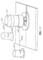
- FIG. 7depicts a block diagram of a tool operating with range finder in accordance with the present invention.
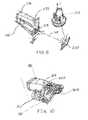
- FIG. 8depicts a nail gun operating with a laser system in accordance with the present invention.
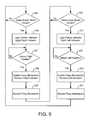
- FIG. 9shows a sequence of steps performed by the nail gun shown in FIG. 8.
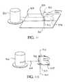
- FIG. 10illustrates a nail gun employing a track ball mechanism in accordance with the present invention.
- FIGS. 11 and 11Adepict a jigsaw operating with a laser system in accordance with the present invention.
- FIG. 12illustrates a circular saw operating with a laser system in accordance with the present invention.
- FIG. 13depicts a router operating with a pair of laser systems in accordance with the present invention.
- FIG. 14shows a router operating with a pair of guide wires in accordance with the present invention.
- FIG. 15shows a drill, including alignment and depth detectors in accordance with the present invention.
- FIGS. 15A and 15Bshow one embodiment of an alignment detector.
- FIG. 16shows one implementation of a depth detector.
- FIG. 16Aillustrates a series of laser patterns provided by the depth detector in FIG. 16.
- FIG. 17shows an alternate implementation of a depth detector.
- FIG. 17Aillustrates a series of laser patterns provided by the depth detector in FIG. 17.
- FIG. 18shows one embodiment of a level detector.
- FIG. 18Ashows laser patterns provided by the level detector in FIG. 18.
- FIG. 19illustrates hardware employed in a tool in one embodiment of the present invention to carry out sequences of operation described below with reference to FIGS. 1 - 14 .
- FIG. 1shows a block diagram of tool 10 , which represents one embodiment of the present invention.
- Nail guns, jigsaws, circular saws, and routersare non-exhaustive examples of the types of tools that tool 10 can be.
- the implementation of nail guns, jigsaws, circular saws, and routers in accordance with the present inventionare described later in greater detail with reference to FIGS. 8 - 14 .
- Tool 10includes action component 22 , which operates on a work piece.
- action component 22include saw blades, router cutting heads, and nail gun firing mechanisms.
- Component controller 16is coupled to action component 22 to control the operation of action component 22 —directing the operation of action component 22 in response to an orientation of tool 10 .
- tool 10does not include component controller 16 , since tool 10 does not adjust the orientation of action component 22 .
- Guide detector 12receives guides from a guide system (not shown) and ascertains the position of the guides relative to tool 10 .
- guide detector 12is a pair of photo diode detectors used to detect the position of laser beams from a laser guidance system.
- Guide detector 12is coupled to location detector 14 to provide position data reflecting the guide positions.
- Location detector 14determines an orientation of tool 10 relative to a work piece on which action component 22 will operate.
- Location detector 14is coupled to component controller 16 to supply information identifying the tool orientation. Controller 16 then uses this orientation information to make adjustments to action component 22 , such as changing the orientation or state of component 22 .
- the orientation informationcorresponds to tool adjustments that component controller 16 must make.
- Location controller 14is also coupled to communication port 18 and indicator set 20 .
- Communication port 18enables location detector 14 to share orientation information with external devices, such as the guide system.
- Indicator set 20provides directional signals to tool operators to assist in steering or aiming tool 10 .
- Indicator set 20is coupled to location detector 14 to receive tool orientation information that controls which indicators are asserted.
- Alternate implementations of tool 10include either indicator set 20 or action component 22 , but not both. Some versions of tool 10 do not include communication port 18 .
- FIG. 1Applications of the block diagram architecture shown in FIG. 1 to specific types of tools, including nail guns, power saws, and routers are described below with reference to FIGS. 8 - 14 .
- FIG. 2shows a sequence of operations performed by one version of tool 10 .
- Guide detector 12receives one or more guide inputs from one or more guide systems, such as a laser beam from a laser system (step 40 ).
- Guide detector 12detects the positions of the guides relative to tool 10 and forwards data identifying the position to location detector 14 (step 42 ).
- Location detector 14employs the position data to determine the orientation of tool 10 with respect to a work piece, such as a piece of wood to be routed by tool 10 (step 44 ).
- the one or more guide systemshave a predefined physical relationship to the work piece. Examples of different guide systems are provided below.
- location detector 14By detecting the orientation of tool 10 , location detector 14 inherently determines the orientation of action component 22 . In this application, the operation of determining the orientation of tool 10 is considered interchangeable with the operation of determining the orientation of action component 22 .
- Action component 22has a known physical displacement from guide detector 12 .
- location detector 14determines the orientation of guide detector 12 , based on the position data, and applies the known physical displacement to determine the orientation of action component 22 .
- Location detector 14determines whether any adjustment needs to be made to tool 10 , based on the identified orientation (step 46 ). Examples of situations where tool adjustments are needed include the following: 1) a jigsaw blade's orientation being out of alignment with a desired cutting line on a work piece, 2) a nail gun's orientation corresponding to a position on a work piece where the gun's firing mechanism should not be enabled, and 3) a router cutting head's orientation corresponding to a location on a work piece where the head's vertical displacement needs to be adjusted.
- step 48If an adjustment is needed, the state of tool 10 is adjusted (step 48 ). Otherwise, no adjustment is made. In either instance, tool 10 continually repeats the process shown in FIG. 2. On example of an adjustment made by tool 10 (step 48 ) is changing the orientation of action component 48 .
- Component controller 16recognizes that the orientation of action component 22 needs to be adjusted, based on orientation information supplied by location detector 14 .
- Component controller 16continues to adjust the orientation of action component 22 , until the orientation information from location detector 14 no longer indicates any adjustment is necessary. For example, component controller 16 continues to adjust the orientation of a jigsaw's blade until location detector 16 indicates that the blade is in line with a desired cutting line.
- step 48Another type of adjustment made by tool 10 is altering the state of action component 22 , based on orientation information supplied by location detector 14 .
- location detector 14recognizes the orientation of tool 10 as corresponding to a desired state of action component 22 .
- Location detector 14then supplies orientation information to component controller 16 —causing controller 16 to place component 22 in the desired state.
- component controller 16enables or disables the firing mechanism of a nail gun, based on the firing mechanism's orientation.
- Tool adjustmentsalso include asserting and deasserting indicators that direct a tool user's operation of tool 10 .
- Indicator set 20 in tool 10responds to the tool orientation provided by location detector 14 to provide the tool's user with proper signaling.
- a router indicator set 20provides directional signals to the tool user—indicating the direction the user should steer the router, based on the router's current orientation on a work piece.
- a light emitting diodeis one type of indicator that can be employed in tool 10 .
- FIG. 3shows tool 10 in use with a single laser system 50 that provides a single laser beam 52 as a guide.
- Examples of a laser projection systems that can be employed as laser system 50are described in U.S. Pat. No. 5,680,208, issued Oct. 21, 1997; 08/953,935, filed Oct. 20, 1997; U.S. Pat. No. 5,903,345, issued May 11, 1999; U.S. Pat. Ser. No. 09/247,750, filed Feb. 9, 1999; U.S. Ser. No. 09/571,482, filed May 16, 2000, and U.S. Pat. Ser. No. 09/928,244, filed Aug. 10, 2001 all of which are included herein by reference.
- Laser system 50can be self-leveling or non-self-leveling.
- the central axis of laser beam 52identifies a path on a work piece, such as a cutting line to be followed by a jigsaw's blade.
- Guide detector 12receives laser beam 52 and identifies the position of laser beam 52 relative to tool 10 .
- guide detector 12includes an array of photo diode detectors. The photo diode detectors are arranged so that each photo diode provides the same signal when tool 10 is oriented with action component 22 in line with the work piece path. When tool 10 is not oriented in this fashion, the photo diode detectors supply unequal signals.
- Location detector 14receives the output of the photo diode detectors. Location detector 14 determines the orientation of tool 10 with respect to the work piece path, based on the position data supplied as output signals from the photo diodes. If all the signals are equal, location detector 14 determines that tool 10 is oriented so that action component 22 is in line with the desired path on the work piece. If the photo diode signals are not all equal, location detector 14 identifies tool 10 as being offset from the work piece path in a direction that corresponds to the strongest photo diode signals. For example, if guide detector 12 has two photo diode to detect beam 52 , the tool is offset to the right of the work piece path if the right most photo diode detector provides a stronger signal than the other detector.
- tool 10does not include communications port 18 .
- communications port 18is included in tool 10 .
- FIG. 4shows tool 10 in use with laser systems 60 and 62 , which provide laser beams 64 and 66 , respectively.
- Tool 10employs beams 64 and 62 to identify the orientation of tool 10 on a work piece in terms of an absolute position, such as an (x,y) coordinate.
- Laser systems 60 and 62are the same as laser system 50 in FIG. 3. In one embodiment, Laser systems 60 and 62 are rotating laser systems. Laser systems 60 and 62 are positioned so that laser beams 64 and 66 each have a predefined point of origin within a coordinate system covering the work piece. For example, a wooden surface to be routed can be described in terms of a two dimensional orthogonal (x,y) coordinate system that includes the points of origin for laser beams 64 and 68 .
- Guide detector 12includes an array of photo diode detectors, as described above with reference to FIG. 3.
- Guide detector 12detects when tool 10 is oriented in a position where laser beams 64 and 66 each intercept the same predetermined location in the array, such as the array's center. This indication is provided as position data in the form of photo diode signal intensity, as described above for guide detector 12 in FIG. 3.
- Guide detector 12also determines the time required for laser beams 64 and 66 to each rotate between the predefined location on the photo diode detector array and axis 68 —the axis line passing through the origin points of laser beams 64 and 66 .
- axis line 68is parallel to one axis in a two dimensional coordinate system encompassing the work piece and perpendicular to the other axis in the two dimensional coordinate system.
- Guide detector 12passes the time measurements to location detector 14 to serve as position data—identifying the positions of laser beams 64 and 66 relative to tool 10 .
- Location detector 14uses the time measurements to determine the orientation of tool 10 .
- Location detector 14determines a (x, y) coordinate for guide detector 12 . This coordinate corresponds to a (x, y) coordinate for action component 22 , which has a known displacement from guide detector 12 .
- the (x, y) coordinate of guide detector 12resides at the intersection of laser beams 64 and 66 .
- Location detector 14employs the laser rotation times to determine x and y displacements for the lines formed by laser beams 64 and 66 .
- the x and y displacementsare then employed by location detector 14 to calculate the x; y offset of guide detector 12 from the known x, y coordinates of the origins of laser beams 64 and 66 .
- location detector 14In order to determine the x, y displacements from laser beams 64 and 66 , location detector 14 employs the following relationships in one embodiment:
- ⁇ 60is the angle between axis line 68 and laser beam 64 within the triangle formed by laser beam 64 , laser beam 62 , and axis line 68 .
- ⁇ 62is the angle between axis line 68 and laser beam 66 within the triangle formed by laser beam 64 , laser beam 62 , and axis line 68 .
- t 60is the time required for laser beam 64 to make a complete revolution.
- t 62is the time required for laser beam 62 to make a complete revolution.
- t 64is the time required for laser beam 64 to traverse angle ⁇ 60 .
- t 66is the time required for laser beam 66 to traverse angle ⁇ 62 .
- L 64is the length of laser beam 64 .
- L 66is the length of laser beam 66 .
- Bis a known distance between the points of origin for laser beam 64 and laser beam 66 .
- x 64is the x axis displacement from the origin of laser beam 64 to the point where laser beam 64 is incident on guide detector 12 .
- y 64is the y axis displacement from the origin of laser beam 64 to the point where laser beam 64 is incident on guide detector 12 .
- x 66is the x axis displacement from the origin of laser beam 66 to the point where laser beam 66 is incident on guide detector 12 .
- y 66is the y axis displacement from the origin of laser beam 66 to the point where laser beam 66 is incident on guide detector 12 .
- location detector 14includes a look-up table that converts time measurements pairs for laser beams 64 and 66 into (x, y) coordinates.
- tool 10receives values for t 64 , t 66 , and B from laser systems 60 and 62 via communications port 18 .
- Communication port 18can communicate with laser systems 60 and 62 using many well-known communication media and protocols.
- Example mediainclude radio frequency, infrared and cable signaling.
- values for t 60 , t 62 , and Bare stored in tool 10 —eliminating the need to use communication port 18 .
- FIG. 5illustrates tool 10 in use with guide wire systems 80 and 82 to determine the orientation of tool 10 .
- tool 10obtains a (x, y) coordinate to serve as the orientation of tool 10 .
- Guide wire system 80anchors guide wire 84
- guide wire system 82anchors guide wire 86 .
- the anchorsreside on axis line 83 , which is the same as axis line 68 in FIG. 4.
- the distance B between the anchor pointsis known to location detector 14 .
- Wires 84 and 86are each coupled to guide detector 12 with a two-spring tension wire real device in guide detector 12 .
- Guide detector 12has a device to measure the displacement distance of wires 84 and 86 .
- the displacement measuring deviceis an encoder attached to the real device to detect the extension of wires 84 and 86 .
- Guide detector 12supplies the wire lengths to location detector 14 as position data that identifies the position of tool 10 relative to guide wire systems 80 and 82 .
- Location detector 14determines the orientation of tool 10 using the wire lengths and the trigonometric principles described above with reference to FIG. 5. Using the law of cosines, the angles between (1) wire 84 and axis 83 and (2) wire 86 and axis 83 can be found. Once the angles are known, location detector 14 can solve for the x and y displacements of wires 84 and 86 to obtain a coordinate for tool 10 .
- FIG. 6depicts tool 10 in operation with track ball mechanism 100 serving as a guide system.
- track ball mechanism 100is a well known rolling sensor used in a computer mouse to determine movements.
- optical tracking systemslike those used in an optical computer mouse can be employed.
- Track ball mechanism 100is attached to tool 10 and provides information identifying changes in the two dimensional (x, y) orientation of the track ball.
- Guide detector 12receives this information and passes it to location detector 14 as position data identifying the position of track ball mechanism 100 .
- Location detector 14employs the two dimensional position data to determine a tool orientation. In one embodiment, location detector 14 applies the x, y changes to the tool's prior x, y coordinates.
- FIG. 7illustrates tool 10 operating with range and angle finder 110 as a guide system.
- Range and angle finder 110determines the displacement of tool 10 from finder 110 and communicates the displacement to communication port 18 .
- a standard range and angle findercan be employed, such as a range and angle finder employing laser, infra red, or radio frequency signaling.
- range and angle finder 110has a rotating range and angle finding signal, while in other embodiments, the range and angle finder signal does not rotate.
- Location detector 14receives the displacement information from communications port 18 and determines the orientation of tool 10 .
- range and angle finder 110supplies the displacement information as a two-dimensional polar coordinate ( ⁇ , r). As shown in FIG. 7, guide detector 12 is not included in tool 10 in the range and angle finder embodiment, since range and angle finder 110 provides coordinates.
- FIG. 8shows nail gun 216 in use with laser system 212 in accordance with the present invention.
- Nail gun 216has the functionality and design described above for tool 10 with reference to FIG. 3.
- Laser system 212operates as described above for laser system 50 in FIG. 3.
- Laser system 212provides laser beam 218 as a guide signal to nail gun 216 .
- beam 218reflects off mirror 220 , but in alternate implementations laser beam 218 is provided directly to nail gun 216 .
- Photo diode detector array 214is mounted on the head of a nail gun 216 to operate as guide detector 12 .
- nail gun 216automatically fires.
- detector array 214is not properly aligned with laser beam 218
- nail gun 216will not fire. This arrangement allows for nail gun 216 to be fired along a line defined by laser beam 218 .
- Nail gun 216includes component controller 16 to set the firing state of the nail firing mechanism in gun 216 based on the gun's orientation.
- nail gun 216only fires nails when the gun is offset from laser beam 218 —creating a staggered nail pattern that avoids splitting natural material such as a rafter or joist member.
- nail gun 216includes directional light emitting diodes (“LEDs”) 232 on top of the gun to serve as indicator set 20 .
- LEDsdirectional light emitting diodes
- Nail gun 216lights a center LED when the gun is directly in line with laser beam 218 and lights either a right or left LED to direct the user to one side of laser beam 218 .
- FIG. 9depicts a series of operation taken by nail gun 216 to create a staggered nail pattern.
- Photo diode array 214combines with location detector 14 to determine whether nail gun 216 is oriented in line with the center of laser beam 218 (step 224 ). Once nail gun 216 is oriented on the center of laser beam 218 , indicator set 20 lights a center LED and a right LED (step 226 ). The right LED shows the tool operator to steer gun 216 to the right.
- Photo diode array 214combines with location detector 14 to determine when nail gun 216 is oriented to the right of laser beam 218 in a position for firing (step 227 ). Once nail gun 216 is in a firing position, component controller 16 enables the gun's firing mechanism, and indicator set 20 deasserts the right LED (step 228 ). In operation, a user has the nail gun trigger pulled when the firing mechanism is enabled—resulting in a nail being driven into the work piece. After the nail is fired, component controller 16 disables the nail gun firing mechanism (step 229 ).
- Photo diode array 214once again combines with location detector 14 to determine whether nail gun 216 is oriented in line with the center of laser beam 218 (step 230 ). Once nail gun 216 is centered, indicator set 20 lights the center LED and a left LED (step 231 ). The left LED shows the tool operator to steer gun 216 to the left.
- Array 214combines with detector 14 to determine when nail gun 216 is oriented to the left of laser beam 218 in a position for firing (step 232 ). Once nail gun 216 is in a firing position, component controller 16 enables the gun's firing mechanism, and indicator set 20 deasserts the left LED (step 233 ). After the nail is fired, component controller 16 disables the nail gun firing mechanism (step 234 ). The above-described process in FIG. 9 is performed repeatedly until all nails are driven into the work piece.
- a two-dimensional array of nailing patternsis preprogrammed into nail gun 216 . This can be done at a factory where gun 216 is manufactured or a job site.
- Key pad 234is mounted to nail gun 216 to facilitate data entry by the tool user. A user employs key pad 234 to enter a nailing pattern or select a preprogrammed nailing pattern.
- nail gun 216operates with a guide system that provides for identifying a coordinate position.
- guide systemsinclude the guide wire system shown in FIG. 5 and the dual laser system shown in FIG. 4.
- Nail gun 216operates as described above for tool 10 in FIGS. 4 and 5 to identify when gun 216 is oriented in line with a position where a nail is to be driven into a work piece.
- component controller 16enables the gun's firing mechanism when location detector 14 indicates gun 216 is oriented in line with a desired nail target.
- the guncan also be programmed for “keep out” areas. On the keep out areas, the gun would not fire, even if the trigger were pulled.
- the keep out areascould be programmed by positioning the nail gun on the periphery of the keep out area and pushing a button on key pad 234 —programming the position of the nailing gun as determined by guide detector 12 and location detector 14 .
- a memory in gun 216records every position where a nail is fired into a work piece—making nail gun 216 self-auditing.
- the nailing patterncan be verified without the use of an inspector by downloading the nail pattern from the memory of nailing gun 216 .
- Such self-auditingmight be quite helpful in situations where precise nailing patterns are desirable.
- a related exampleis a similar application of placing rivets on an aircraft wing.
- FIG. 10depicts an embodiment of the present invention with nail gun 302 employing rolling sensor 304 as a guide system.
- rolling sensor 304is track ball mechanism 100 shown in FIG. 6.
- Nail gun 302includes the functionality and design described for tool 10 in FIG. 6, as well as key pad 306 .
- Nail gun 302allows a user to select a nail spacing pattern and only enables the gun's firing mechanism once rolling sensor 304 indicates the nailing gun is in the right position.
- Nail gun 302determines its orientation by evaluating the guide signals from rolling sensor 304 using guide detector 12 and location detector 14 , as described above with reference to FIG. 6. Location detector 14 then compares the detected orientation to the desired nail target.
- indicator set 20(FIG. 6) lights LED 308 to inform the user to pull the gun's trigger.
- nail gun 302When nailing a piece of plywood or sheet rock with nail gun 302 , a user can hold onto the trigger of gun 302 , and slide gun 302 in a straight line. Nail gun 302 only fires in exact spacing increments, such as for example, every six inches. In another embodiment, a stud sensing system 310 , which is known in the art, is added to nail gun 302 . Nail gun 302 does not fire unless appropriately aligned with a stud underneath. In another implementation, nail gun 302 includes electrical voltage sensor 312 so that gun 302 does not fire if the nailing pattern interrupts an electric wire.
- FIGS. 11 and 11Adepict jigsaw 404 in use with laser system 402 to ensure that jigsaw 404 follows a cutting line defined by laser beam 408 .
- Jigsaw 404includes the functionality and design of tool 10 described in FIG. 3, and laser system 402 is the same as laser system 50 in FIG. 3.
- Jigsaw 404employs photo diode detector array 406 to detect laser beam 408 in the same way guide detector 12 was described to operate in FIG. 3.
- Jigsaw 404also includes location detector 14 to determine the orientation of jigsaw 404 and determine whether an orientation adjustment is necessary.
- jigsaw 404is a scroll type jigsaw with manual handle 410 , which can direct the orientation of blade 412 .
- Component controller 16 in saw 404also controls the orientation of blade 412 —driving a steering motor (not shown) attached to blade 412 to rotate blade 412 about its longitude axis 414 .
- location detector 14detects this occurrence and instructs component controller 16 to adjust the orientation of blade 412 .
- Component controller 16drives the steering motor to rotate blade 412 —keeping blade 412 in line with laser beam 408 .
- FIG. 12shows circular saw 502 operating in conjunction with laser system 504 to ensure that saw 502 follows a predetermined cutting line defined by laser beam 508 .
- Circular saw 502 and laser system 504are the same as tool 10 and laser system 50 from FIG. 3.
- Circular saw 502includes photo diode detector array 506 to serve as guide detector 12 .
- Photo diode detector array 304is mounted on the front of a circular saw 502 , such that the position of beam 508 relative to saw 502 is detected.
- Array 506combines with location detector 14 to determine the orientation of saw 502 and whether any orientation corrections need to be made for the saw's blade to stay in line with laser beam 508 .
- a userprovides a manual push to propel saw 502 .
- location detector 14signals component controller 16 .
- component controller 16drives motor steering mechanism 510 to change the orientation of the saw's blade to come in line with laser beam 508 .
- a blade velocity gaugereplaces motor steering mechanism 510 to implement angular velocity ripple.
- One half of the bladehas teeth bent to the right, and the other half of the blade as teeth bent to the left.
- the velocity gaugeresponds to an orientation correction signal from component controller 16 by increasing the rotational speed of the blade for half a rotation. The increased speed steers the saw toward the direction of the teeth with enhanced speed.
- alignment pistons 512 and 514are employed in lieu of motor steering mechanism 510 and the above-described velocity gauge. Pistons 512 and 514 are positioned between circular saw 502 and handle 516 , which a user employs to propel and steer saw 502 . Component controller 16 issues signals to control alignment pistons 512 and 514 —causing pistons 512 to 514 to adjust their lengths to bring the saw blade in line with laser beam 508 . Examples of pistons 512 and 514 include pneumatic pistons and hydraulic pistons for a large saw arrangement. Alternatively, pistons 512 and 514 are mechanical pistons, extending or retracting in response to a rack and pinion arrangement driven by a motor.
- FIG. 13shows router 601 in use with lasers 602 a and 602 b to ensure the proper orientation of the router's cutting head.
- Router 601includes the functionality and design of tool 10 in FIG. 4, and laser systems 602 a and 602 b are the same as laser systems 60 and 62 in FIG. 4.
- Photo diode detector array 604is mounted on router 601 to serve as guide detector 12 .
- Array 604combines with location detector 14 to receive laser beams 603 a and 603 b from lasers 602 a and 602 b and determine the orientation of router 601 .
- location detector 14determines the orientation of router 601 in terms of an absolute position, such as a (x, y) coordinate. Based on the router's orientation, location detector 14 determines whether any tool adjustments are needed.
- location detector 14instructs component controller 16 to adjust the vertical displacement of the router's cutting head, based on the detected orientation.
- Component controller 16directs the operation of a motor that moves the cutting head along a vertical axis.
- a memory in router 601stores relief patterns, such as those used for carvings or cabinet face panel configurations. The vertical displacement of the cutting head is set to follow the desired depth of cut for each position in the relief pattern. This allows a user to simply move router 601 back and forth across a work piece, while router 601 automatically adjusts the height of the router cutting head.
- location detector 14sends control signals to indicator set 20 —showing a user the direction to steer router 601 for a selected relief pattern by illuminating lights 606 .
- router 601only employs a single laser system, such as laser system 602 a .
- Router 601uses array 604 and location controller 14 to control lights 606 , so a user receives steering directions for keeping router 601 in line with laser beam 603 a.
- FIG. 14shows router 702 in use with guide wires 704 and 706 to achieve the same functionality as described above for router 601 .
- Router 702has the same functionality and design as router 10 in FIG. 5, and guide wires 704 and 706 operate the same as guide wires 84 and 86 in FIG. 5.
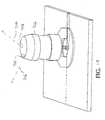
- FIG. 15shows tool 802 with depth detector 812 and alignment detector 804 .
- tool 802is shown as a drill. In alternate embodiments, however, tool 802 can be a variety of different tools, such as a nail gun.
- tool 802includes the functionality and design described for tool 10 in FIGS. 1 - 7 . In alternate embodiments, tool 802 only includes a subset or none of the functionality described for tool 10 above.
- Alignment detector 804is attached to the head of the drill 804 and provides laser light grid 806 .
- Grid 806appears on a work piece as a set of perpendicular lines, resembling a tic-tac-toe grid, when face 799 of alignment detector 804 is parallel to the surface of the work piece.
- Alignment detector 804is attached to drill 802 so the tic-tac-toe grid appears when the drill bit in drill 802 is normal to the surface of the work piece.
- Grid 806includes parallel lines 805 and 807 , which are perpendicular to parallel grid lines 801 and 803 .
- a set of laser planes extending from alignment guide 804form laser lines 801 and 803 .
- Another set of laser planes extending from alignment guide 804form laser lines 805 and 807 .
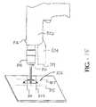
- FIG. 15Ashows a side view of hardware employed in alignment detector 804 to form grid 806 .
- FIG. 15Bshows a side view of the same hardware in FIG. 15A rotated by 90 degrees.
- Alignment detector 804includes laser sources 810 , 1810 , 2810 , and 3810 and optical elements 809 , 1809 , 2809 , and 3809 mounted in a housing (not shown).
- laser sources 810 , 1810 , 2810 , and 3810are laser diodes
- optical elements 809 , 1809 , 2809 , and 3809are holographic elements.
- optical elements 809 , 1809 , 2809 , and 3809can be cylindrical lenses in alternate embodiments.
- Laser diodes 810 , 1810 , 2810 , and 3810deliver laser beams 811 , 1811 , 2811 , and 3811 to holographic plates 809 , 1809 , 2809 , and 3809 , respectively.
- Laser beams 811 , 1811 , 2811 , and 3811are schematic representations of the actual laser beams from diodes 810 , 1810 , 2810 , and 3810 .
- laser diodes 810 , 1810 , 2810 , and 3810each output a diverging laser beam that impacts a substantial portion or all of holographic plates 809 , 1809 , 2809 , and 3809 , respectively.
- Holographic plates 809 , 1809 , 2809 , and 3809convert laser beams 811 , 1811 , 2811 , and 3811 into a first laser plane set including converging laser planes 801 and 803 , and a second laser plane set including converging laser planes 805 and 807 .
- the planes from optical element 2809is not shown in FIG. 15A, and the plane for optical element 809 is not shown in FIG. 15B.
- Planes 801 , 803 , 805 , and 807form laser lines 801 , 803 , 805 , and 807 , respectively, on the incident surface of a work piece.
- Alignment detector 804can be aligned so that planes 801 , 803 , 805 , and 807 are incident on a surface either before or after the location where the planes intersect.
- alignment detector 804includes collimating lenses between lasers 810 , 1810 , 2810 , and 3810 and holographic plates 809 , 1809 , 2809 and 3809 , respectively.
- planes 801 and 803originate from their respective optical elements as diverging planes. This is also true for planes 805 and 807 .
- convergingis used in this application to explain planes' initial orientation to each other at one point in space. As those skilled in the art recognize, converging planes, like those shown in FIGS. 15A and 15B, begin to diverge from each other after intersecting.
- spinning laserscan be employed to create laser lines 801 , 803 , 805 , and 807 .
- fewer than four laser sourcesare employed to generate laser beams 811 , 1811 , 2811 , and 3811 .
- one laser sourcecan be employed with multiple beam splitters, or other mechanisms for dividing a laser beam, to form beams 811 , 1811 , 2811 , and 3811 . Numerous combinations of laser sources and beam dividing mechanisms are possible.
- Depth detector 812determines the work piece depth reached by the bit on drill 802 . Depth detector 812 is mounted to rotating chuck 814 of drill 802 . Depth detector 812 determines when a preset depth has been reached and illuminates light 816 on drill 802 to inform the user that the appropriate depth had been obtained.
- depth detector 812includes a sonar system similar to those employed in camera systems or a pin diode system.
- a deviceis provided in drill 802 to measure the revolutions per minute of drill chuck 814 .
- Computational meanssuch as a microprocessor, can then be provided to calculate the depth of the drilling action and the orientation of the drill bit relative to the work surface by knowing the angular speed and position of chuck 814 .
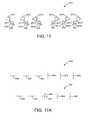
- FIGS. 16 and 17show an alternate embodiment of a depth detector 813 that can be attached to tool 802 .
- the depth detector shown in FIGS. 16 and 17is mounted to tool 802 on a stationary portion of the tool, like the way alignment detector 804 is attached to tool 802 .
- Depth detector 813generates laser patterns, as shown in FIGS. 16A and 17A, to indicate the depth of tool 802 .
- Depth detector 813includes laser sources 815 , 1815 , 2815 , 3815 , 4815 , and 5815 and optical elements 819 , 1819 , 2819 , 3819 , 4819 , and 5819 mounted in a housing (not shown).
- laser sources 815 , 1815 , 2815 , 3815 , 4815 , and 5815are laser diodes
- optical elements 819 , 1819 , 2819 , 3819 , 4819 , and 5819are holographic plates.
- Laser diodes 815 , 1815 , 2815 , 3815 , 4815 , and 5815supply laser beams 817 , 1817 , 2817 , 3817 , 4817 , and 5817 to holographic plates 819 , 1819 , 2819 , 3819 , 4819 , and 5819 , which generate a set of laser planes.
- the laser planesimpact on a work piece surface they form patterns that correspond to the distance between depth detector 813 and the work piece.
- FIGS. 16A and 17Ashow example laser patterns.
- depth detector 813employs optical elements other than holographic plates, such as cylindrical lenses, to generate the patterns in FIGS. 16A and 17A.
- depth detector 813includes a collimating lens between the laser sources and optical elements.
- Laser pattern 820 in FIG. 16Aincludes a first set of lines 828 , 830 and 832 and a second set of lines 826 , 824 , and 822 .
- Depth detector 813generates pattern 820 by emitting two sets of converging laser planes. As shown in FIGS. 16 and 16A, the three planes in the first set are parallel to each other and form lines 828 , 830 , and 832 when they impact on a work piece.
- the three planes in the second setare parallel to each other and form lines 826 , 824 , and 822 when they impact on a work piece. Planes in the first set forming lines 828 , 830 , and 832 converge with the planes in the second set forming lines 826 , 824 , and 822 .
- the lines from the first set of laser planes and the lines from the second set of laser planesbegin to move towards each other and eventually overlap, as shown in pattern 834 .
- the tool operatordetermines the depth reached by tool 802 , based on the laser line pattern produced by depth detector 812 .
- the appearance of lines 828 , 830 , and 832are differentiated from the appearance of lines 826 , 824 , and 822 .
- one set of laser linesis generated as dashed lines.
- pattern 840 from depth detector 813includes a set of horizontal lines 848 , 850 , and 852 and a set of vertical lines 842 , 844 , and 846 .
- Each line in pattern 840comes from a laser plane from depth detector 813 impacting a work piece surface. As shown in FIG. 17A,
- 17, depth detector 813includes holographic plates 819 , 1819 , 2819 , 3819 , 4819 , and 5819 to convert laser beams 817 , 1817 , 2817 , 3817 , 4817 , and 5817 , respectively, into the following: a first set of planes that form horizontal lines 848 , 850 , and 852 on a work piece and a second set of laser planes that form vertical lines 842 , 844 , and 846 on a work piece.
- the first set of planesis angled to converge with the second set of planes.
- Pattern 841shows how the set of vertical lines overlaps with the set of horizontal lines as depth detector 813 moves closer to the work piece.
- depth detector 813is designed so a vertical line and horizontal line form a cross when tool 802 reaches a predefined depth.
- demarcations other than linescan be employed, such as crosses or stars.
- FIG. 18shows a level detector 860 employed on a tool in one embodiment of the present invention.
- level detector 860is included on a tool with the functionality described above for tools 10 and 802 .
- level detector 860is included on a tool with a subset or none of the functionality described for tools 10 and 802 .
- level detector 860is included in a leveling tool that only performs level detection operations.
- Level detector 860includes laser sources 862 and 1862 providing laser beams 864 and 1864 to optical elements 866 and 1866 , respectively.
- the components of laser detector 860are mounted in a housing (not shown).
- laser sources 862 and 1862are laser diodes
- optical elements 866 and 1866are holographic plates.
- a collimating lensis inserted between holographic plates 866 and 1866 and laser diodes 862 and 1862 , respectively.
- Holographic plates 866 and 1866convert laser beams 864 and 1864 into converging laser planes 870 and 868 , respectively. Planes 868 and 870 intersect along line 872 .
- level detector 860is suspended above the surface of a work piece, such as the top of a counter.
- level detector 860is adjustably mounted on a tool, so its position with respect to a work surface can be modified.
- Level detector 860is positioned so intersection line 872 is incident on the work piece surface. As shown in FIG. 18A, this creates single laser line 872 on the work piece surface—showing the tool user that the surface is level in the area where line 872 appears.
- single laser line 872diverges into laser line segments 868 and 870 —indicating a surface area section that is not level with the area where line 872 appears.
- the diverging diagonal portions of laser line segments 868 and 870indicate that the work piece surface is sloped.
- the parallel portions of laser line segments 868 and 870indicate that the work piece surface is level, but offset from the area where line 872 exists.
- Level detector 860 in FIG. 18has broad applicability.
- level detector 860is mounted on a laser guide, as described above, to ensure that a rotating laser plane provided by the guide is perpendicular to a surface.
- level detector 860is mounted to the laser device so intersection line 872 appears on the target surface, or a parallel surface, when the laser plane is perpendicular.
- level detector 860is employed when shimming a counter top.
- the counteris shimmed, until only intersection line 872 appears on the counter. If multiple lines 868 and 870 appear additional wedges are added under the counter surface.
- Leveling a counter top in multiple directionscan be achieved by using multiple level detectors or a modified version of level detector 860 .
- the modified versionincludes multiple level detectors, like the one shown in FIG. 18, to produce laser leveling signal's from multiple sides of the device.
- Level detector 860can also be used to determine whether a wall is plumb, by placing the detector at the wall's base or top. If only intersection line 872 appears, the wall in plumb. If multiple diverging laser lines appear, the wall is not plumb.
- FIG. 19illustrates a high level block diagram of general purpose computer system 900 .
- System 900may be employed in embodiments of the present invention to provide the functionality for guide detector 12 , location detector 14 , component controller 16 , communications port 18 , and indicator set 20 .
- System 900may be employed on tool 10 or remote from tool 10 , but in either circumstance is considered to be part of tool 10 . Accordingly, computer system 900 may be employed for performing a number of processes, including those described above with reference to FIGS. 1 - 14 .
- Computer system 900contains processing unit 905 , main memory 910 , and interconnect bus 925 .
- Processing unit 905may contain a single microcontroller, single microprocessor, or a plurality of microcontrollers or microprocessors for configuring computer system 900 as a multi-processor system.
- Processing unit 905is employed in conjunction with a memory or other data storage medium containing application specific program code instructions to implement the functionality of guide detector 12 , location detector 14 , and component controller 16 .
- Main memory 910stores, in part, instructions and data for execution by processing unit 905 . If a process, such as the processes described with reference to FIGS. 1 - 14 , is wholly or partially implemented in software, main memory 910 can store the executable instructions for implementing the process when the computer is in operation. For example, main memory 910 can store program code instructions employed by guide detector 12 , location detector 14 , and component controller 16 . In one implementation, main memory 910 includes banks of dynamic random access memory (DRAM) as well as high speed cache memory.
- DRAMdynamic random access memory
- computer system 900further include mass storage device 920 , peripheral device(s) 930 , portable storage medium drive(s) 940 , input control device(s) 970 , graphics subsystem 950 , and output display 960 .
- computer system 900does not include all of the devices shown in FIG. 19.
- computer system 900may be connected through one or more data transport means in alternate implementations.
- processing unit 905 and main memory 910may be connected via a local microprocessor bus
- mass storage device 920 , peripheral device(s) 930 , portable storage medium drive(s) 940 , and graphics subsystem 950may be connected via one or more input/output busses.
- Mass storage device 920is a non-volatile storage device for storing data and instructions for use by processing unit 905 .
- Mass storage device 920can be implemented in a variety of ways, including a magnetic disk drive or an optical disk drive.
- mass storage device 920stores the instructions executed by computer system 900 to perform processes such as those described with reference to FIGS. 1 - 14 .
- Portable storage medium drive 940operates in conjunction with a portable non-volatile storage medium to input and output data and code to and from computer system 900 .
- storage mediumsinclude floppy disks, compact disc read only memories (CD-ROM), memory sticks, and integrated circuit non-volatile memory adapters (i.e. PC-MCIA adapter).
- the instructions for enabling computer system 900 to execute processes, such as those described with reference to FIGS. 1 - 14are stored on such a portable medium, and are input to computer system 900 via portable storage medium drive 940 .
- Peripheral device(s) 930may include any type of computer support device, such as an input/output interface, to add additional functionality to computer system 900 .
- peripheral device(s) 930may include a communications controller, such as a network interface card or integrated circuit, for interfacing computer system 900 to a communications network or point-to-point links with other devices.
- Instructions for enabling computer system 900 to perform processes, such as those described with reference to FIGS. 1 - 14may be downloaded into the computer system's main memory 910 over a communications network.
- Computer system 900may also interface to a database management system over a communications network or other medium that is supported by peripheral device(s) 930 .
- Input control device(s) 970provide a portion of the user interface for a user of computer system 900 .
- Input control device(s) 970may include an alphanumeric keypad for inputting alphanumeric and other key information, a cursor control device, such as a mouse, a track ball, stylus, or cursor direction keys.
- computer system 900contains graphics subsystem 950 and output display 960 .
- Output display 960can include a cathode ray tube display or liquid crystal display.
- Graphics subsystem 950receives textual and graphical information, and processes the information for output to output display 960 .
- the components contained in computer system 900are those typically found in general purpose computer systems. In fact, these components are intended to represent a broad category of such computer components that are well known in the art.
- the process steps and other functions described above with respect to embodiments of the present inventionmay be implemented as software instructions. More particularly, the process steps described with reference to FIGS. 1 - 14 may be implemented as software instructions.
- the softwareincludes a plurality of computer executable instructions for implementation on a general purpose or application specific computer system. Prior to loading into a computer system, the software instructions may reside as encoded information on a computer readable medium, such as a magnetic floppy disk, magnetic tape, and compact disc read only memory (CD-ROM).
- circuitsmay be developed to perform the process steps and other functions described herein.
Landscapes
- Engineering & Computer Science (AREA)
- Mechanical Engineering (AREA)
- Physics & Mathematics (AREA)
- Life Sciences & Earth Sciences (AREA)
- General Life Sciences & Earth Sciences (AREA)
- General Physics & Mathematics (AREA)
- Geophysics (AREA)
- Length Measuring Devices By Optical Means (AREA)
- Machine Tool Sensing Apparatuses (AREA)
- Conveying And Assembling Of Building Elements In Situ (AREA)
- Numerical Control (AREA)
Abstract
Description
- This application claims the benefit of U.S. Provisional Application No. 60/270,733, “Manually Guided, Self-Correcting, Power Tools,” filed on Feb. 22, 2001, and U.S. Provisional Application No. 60/271,844, “Manually Guided, Self-Correcting, Power Tools,” filed on Feb. 27, 2001, both of which are incorporated herein by reference.[0001]
- This Application is related to the following Application:[0002]
- “Detecting Tool Orientation, Alignment, Depth, and Leveling,” by Andrew Butler, Christopher A. Tacklind, Lance Reisman, Aragon Burlingham, Dan Adams, Gene Duval, William Scott, Rick Feffer, and Jon Carver, Attorney Docket No. TOOLZ-01104US0, filed the same day as the present application, and incorporated herein by reference.[0003]
- 1. Field of the Invention[0004]
- The present invention is directed to a tool system with orientation detection.[0005]
- 2. Description of the Related Art[0006]
- Power tool operators often need to perform precise operations with their tools. Examples of such operations include the following: cutting a surface along a straight line, routing a detailed pattern into a surface, and driving nails into a surface in conformance with a predefined pattern or spacing.[0007]
- Current power tools don't provide efficient mechanisms for aiding operational accuracy. For example, a circular saw operator can restrict the saw's blade to a desired line by mounting a heavy set of guide rails to a cutting surface. This type of guidance mechanism is cumbersome to transport and limited in the number of applications it supports.[0008]
- In many instances, tool operators must rely on their own hand-eye coordination to make orientation adjustments during a tool's operation. No mechanism is provided to dynamically orient or assist in the orientation of the tool's operational action component, such as a saw blade, nail gun firing mechanism, or router cutting head.[0009]
- Accordingly, there is a need for a power tool that dynamically adjusts or assists users in adjusting tool orientation.[0010]
- The present invention, roughly described, pertains to a tool that detects its orientation on a work piece. In some implementations, the tool self adjusts or assists users in making tool adjustments, based on the detected orientation. Nail guns, jigsaws, circular saws, and routers serve as a partial list of tools in which this functionality is useful.[0011]
- In one embodiment, a tool is employed along with a guide system that supplies a guide signal to identify a line on a work piece, such as a wood surface. The tool detects the guide signal and determines the tool's orientation with respect to the line on the work piece. In a further embodiment, the guide system supplies the tool with guide signals that enable the tool to determine its absolute position on the work piece. For example, the tool can employ the guide signals to determine the tool's (x, y) coordinate orientation on a surface.[0012]
- One example of a guide system is a laser projector that supplies one or multiple laser beams. The tool includes an array of photo diode detectors to detect the positions of the laser beams relative to the tool. The tool determines its orientation, based on the detected laser beam positions. Alternate guide systems include guide wires, track balls, and range finders.[0013]
- The tool employs its detected orientation to enhance tool performance. In one implementation, the tool adjusts its orientation. For example, a jigsaw rotates its blade after determining that the current orientation will not yield the desired cut. In another implementation, the tool provides a user with steering directions, based on the determined orientation. In one instance, a nail gun employs a set of directional indicators to show a user the necessary movement of the gun to reach a desired target.[0014]
- In further embodiments, tools make alternate adjustments based on the determined orientation. A router adjusts the vertical displacement of its cutting head, based on the router's orientation on a work piece. A nail gun enables and disables its nail firing mechanism, based on the gun's orientation on a work piece. Those skilled in the art will recognize that the application of the present invention to nail guns, saws, and routers are only exemplars of the invention's utility. Embodiments of the present invention can be implemented in a variety of tools.[0015]
- The present invention can be accomplished using hardware, software, or a combination of both hardware and software. The software used for the present invention is stored on one or more processor readable storage media including hard disk drives, CD-ROMs, DVDs, optical disks, floppy disks, tape drives, RAM, ROM, memory sticks or other suitable storage devices. In alternative embodiments, some or all of the software can be replaced by dedicated hardware including custom integrated circuits, gate arrays, FPGAs, PLDs, and special purpose computers.[0016]
- These and other objects and advantages of the present invention will appear more clearly from the following description.[0017]
- FIG. 1 depicts a block diagram of a tool in accordance with the present invention.[0018]
- FIG. 2 illustrates a series of operations performed by the tool shown in FIG. 1.[0019]
- FIG. 3 shows a block diagram of a tool operating with a laser system in accordance with the present invention.[0020]
- FIG. 4 depicts a block diagram of a tool operating with a pair of laser systems in accordance with the present invention.[0021]
- FIG. 5 shows a block diagram of a tool operating with a pair of guide wires in accordance with the present invention.[0022]
- FIG. 6 illustrates a block diagram of a tool operating with a track ball mechanism in accordance with the present invention.[0023]
- FIG. 7 depicts a block diagram of a tool operating with range finder in accordance with the present invention.[0024]
- FIG. 8 depicts a nail gun operating with a laser system in accordance with the present invention.[0025]
- FIG. 9 shows a sequence of steps performed by the nail gun shown in FIG. 8.[0026]
- FIG. 10 illustrates a nail gun employing a track ball mechanism in accordance with the present invention.[0027]
- FIGS. 11 and 11A depict a jigsaw operating with a laser system in accordance with the present invention.[0028]
- FIG. 12 illustrates a circular saw operating with a laser system in accordance with the present invention.[0029]
- FIG. 13 depicts a router operating with a pair of laser systems in accordance with the present invention.[0030]
- FIG. 14 shows a router operating with a pair of guide wires in accordance with the present invention.[0031]
- FIG. 15 shows a drill, including alignment and depth detectors in accordance with the present invention.[0032]
- FIGS. 15A and 15B show one embodiment of an alignment detector.[0033]
- FIG. 16 shows one implementation of a depth detector.[0034]
- FIG. 16A illustrates a series of laser patterns provided by the depth detector in FIG. 16.[0035]
- FIG. 17 shows an alternate implementation of a depth detector.[0036]
- FIG. 17A illustrates a series of laser patterns provided by the depth detector in FIG. 17.[0037]
- FIG. 18 shows one embodiment of a level detector.[0038]
- FIG. 18A shows laser patterns provided by the level detector in FIG. 18.[0039]
- FIG. 19 illustrates hardware employed in a tool in one embodiment of the present invention to carry out sequences of operation described below with reference to FIGS.[0040]1-14.
- A. Tool Architecture and Operation[0041]
- FIG. 1 shows a block diagram of[0042]
tool 10, which represents one embodiment of the present invention. Nail guns, jigsaws, circular saws, and routers are non-exhaustive examples of the types of tools thattool 10 can be. The implementation of nail guns, jigsaws, circular saws, and routers in accordance with the present invention are described later in greater detail with reference to FIGS.8-14. - [0043]
Tool 10 includesaction component 22, which operates on a work piece. Examples ofaction component 22 include saw blades, router cutting heads, and nail gun firing mechanisms.Component controller 16 is coupled toaction component 22 to control the operation ofaction component 22—directing the operation ofaction component 22 in response to an orientation oftool 10. In alternate implementations,tool 10 does not includecomponent controller 16, sincetool 10 does not adjust the orientation ofaction component 22. - [0044]
Guide detector 12 receives guides from a guide system (not shown) and ascertains the position of the guides relative totool 10. In one embodiment,guide detector 12 is a pair of photo diode detectors used to detect the position of laser beams from a laser guidance system.Guide detector 12 is coupled tolocation detector 14 to provide position data reflecting the guide positions.Location detector 14 determines an orientation oftool 10 relative to a work piece on whichaction component 22 will operate.Location detector 14 is coupled tocomponent controller 16 to supply information identifying the tool orientation.Controller 16 then uses this orientation information to make adjustments toaction component 22, such as changing the orientation or state ofcomponent 22. In some embodiments, the orientation information corresponds to tool adjustments thatcomponent controller 16 must make. - [0045]
Location controller 14 is also coupled tocommunication port 18 and indicator set20.Communication port 18 enableslocation detector 14 to share orientation information with external devices, such as the guide system. Indicator set20 provides directional signals to tool operators to assist in steering or aimingtool 10. Indicator set20 is coupled tolocation detector 14 to receive tool orientation information that controls which indicators are asserted. Alternate implementations oftool 10 include either indicator set20 oraction component 22, but not both. Some versions oftool 10 do not includecommunication port 18. - Applications of the block diagram architecture shown in FIG. 1 to specific types of tools, including nail guns, power saws, and routers are described below with reference to FIGS.[0046]8-14.
- FIG. 2 shows a sequence of operations performed by one version of[0047]
tool 10.Guide detector 12 receives one or more guide inputs from one or more guide systems, such as a laser beam from a laser system (step40).Guide detector 12 detects the positions of the guides relative totool 10 and forwards data identifying the position to location detector14 (step42).Location detector 14 employs the position data to determine the orientation oftool 10 with respect to a work piece, such as a piece of wood to be routed by tool10 (step44). In order to facilitate the orientation determination bylocation detector 14, the one or more guide systems have a predefined physical relationship to the work piece. Examples of different guide systems are provided below. - By detecting the orientation of[0048]
tool 10,location detector 14 inherently determines the orientation ofaction component 22. In this application, the operation of determining the orientation oftool 10 is considered interchangeable with the operation of determining the orientation ofaction component 22.Action component 22 has a known physical displacement fromguide detector 12. When detecting the orientation oftool 10 in one embodiment,location detector 14 determines the orientation ofguide detector 12, based on the position data, and applies the known physical displacement to determine the orientation ofaction component 22. - [0049]
Location detector 14 determines whether any adjustment needs to be made totool 10, based on the identified orientation (step46). Examples of situations where tool adjustments are needed include the following: 1) a jigsaw blade's orientation being out of alignment with a desired cutting line on a work piece, 2) a nail gun's orientation corresponding to a position on a work piece where the gun's firing mechanism should not be enabled, and 3) a router cutting head's orientation corresponding to a location on a work piece where the head's vertical displacement needs to be adjusted. - If an adjustment is needed, the state of[0050]
tool 10 is adjusted (step48). Otherwise, no adjustment is made. In either instance,tool 10 continually repeats the process shown in FIG. 2. On example of an adjustment made by tool10 (step48) is changing the orientation ofaction component 48.Component controller 16 recognizes that the orientation ofaction component 22 needs to be adjusted, based on orientation information supplied bylocation detector 14.Component controller 16 continues to adjust the orientation ofaction component 22, until the orientation information fromlocation detector 14 no longer indicates any adjustment is necessary. For example,component controller 16 continues to adjust the orientation of a jigsaw's blade untillocation detector 16 indicates that the blade is in line with a desired cutting line. - Another type of adjustment made by tool[0051]10 (step48) is altering the state of
action component 22, based on orientation information supplied bylocation detector 14. In this embodiment,location detector 14 recognizes the orientation oftool 10 as corresponding to a desired state ofaction component 22.Location detector 14 then supplies orientation information tocomponent controller 16—causingcontroller 16 to placecomponent 22 in the desired state. For example,component controller 16 enables or disables the firing mechanism of a nail gun, based on the firing mechanism's orientation. - Tool adjustments (step[0052]48) also include asserting and deasserting indicators that direct a tool user's operation of
tool 10. Indicator set20 intool 10 responds to the tool orientation provided bylocation detector 14 to provide the tool's user with proper signaling. For example, in a router indicator set20 provides directional signals to the tool user—indicating the direction the user should steer the router, based on the router's current orientation on a work piece. A light emitting diode is one type of indicator that can be employed intool 10. - B. Employing Different Guide Systems[0053]
- FIG. 3 shows[0054]
tool 10 in use with asingle laser system 50 that provides asingle laser beam 52 as a guide. Examples of a laser projection systems that can be employed aslaser system 50 are described in U.S. Pat. No. 5,680,208, issued Oct. 21, 1997; 08/953,935, filed Oct. 20, 1997; U.S. Pat. No. 5,903,345, issued May 11, 1999; U.S. Pat. Ser. No. 09/247,750, filed Feb. 9, 1999; U.S. Ser. No. 09/571,482, filed May 16, 2000, and U.S. Pat. Ser. No. 09/928,244, filed Aug. 10, 2001 all of which are included herein by reference. - [0055]
Laser system 50 can be self-leveling or non-self-leveling. The central axis oflaser beam 52 identifies a path on a work piece, such as a cutting line to be followed by a jigsaw's blade.Guide detector 12 receiveslaser beam 52 and identifies the position oflaser beam 52 relative totool 10. In one implementation,guide detector 12 includes an array of photo diode detectors. The photo diode detectors are arranged so that each photo diode provides the same signal whentool 10 is oriented withaction component 22 in line with the work piece path. Whentool 10 is not oriented in this fashion, the photo diode detectors supply unequal signals. - [0056]
Location detector 14 receives the output of the photo diode detectors.Location detector 14 determines the orientation oftool 10 with respect to the work piece path, based on the position data supplied as output signals from the photo diodes. If all the signals are equal,location detector 14 determines thattool 10 is oriented so thataction component 22 is in line with the desired path on the work piece. If the photo diode signals are not all equal,location detector 14 identifiestool 10 as being offset from the work piece path in a direction that corresponds to the strongest photo diode signals. For example, ifguide detector 12 has two photo diode to detectbeam 52, the tool is offset to the right of the work piece path if the right most photo diode detector provides a stronger signal than the other detector. - Those of ordinary skill in the art will recognize that numerous types and arrangements of laser beam detectors can be employed in[0057]
guide detector 12 to achieve the above-described operation oftool 10. As shown in FIG. 3,tool 10 does not includecommunications port 18. In alternate embodiments of a single laser application,communications port 18 is included intool 10. - FIG. 4 shows[0058]
tool 10 in use withlaser systems laser beams Tool 10 employsbeams tool 10 on a work piece in terms of an absolute position, such as an (x,y) coordinate.Laser systems laser system 50 in FIG. 3. In one embodiment,Laser systems Laser systems laser beams laser beams - [0059]
Guide detector 12 includes an array of photo diode detectors, as described above with reference to FIG. 3.Guide detector 12 detects whentool 10 is oriented in a position wherelaser beams guide detector 12 in FIG. 3.Guide detector 12 also determines the time required forlaser beams axis 68—the axis line passing through the origin points oflaser beams axis line 68 is parallel to one axis in a two dimensional coordinate system encompassing the work piece and perpendicular to the other axis in the two dimensional coordinate system.Guide detector 12 passes the time measurements tolocation detector 14 to serve as position data—identifying the positions oflaser beams tool 10.Location detector 14 uses the time measurements to determine the orientation oftool 10.Location detector 14 determines a (x, y) coordinate forguide detector 12. This coordinate corresponds to a (x, y) coordinate foraction component 22, which has a known displacement fromguide detector 12. - The (x, y) coordinate of[0060]
guide detector 12 resides at the intersection oflaser beams Location detector 14 employs the laser rotation times to determine x and y displacements for the lines formed bylaser beams location detector 14 to calculate the x; y offset ofguide detector 12 from the known x, y coordinates of the origins oflaser beams - In order to determine the x, y displacements from[0061]
laser beams location detector 14 employs the following relationships in one embodiment: - wherein:[0063]
- θ[0064]60is the angle between
axis line 68 andlaser beam 64 within the triangle formed bylaser beam 64,laser beam 62, andaxis line 68. - θ[0065]62is the angle between
axis line 68 andlaser beam 66 within the triangle formed bylaser beam 64,laser beam 62, andaxis line 68. - t[0066]60is the time required for
laser beam 64 to make a complete revolution. - t[0067]62is the time required for
laser beam 62 to make a complete revolution. - t[0068]64is the time required for
laser beam 64 to traverse angle θ60. - t[0069]66is the time required for
laser beam 66 to traverse angle θ62. - From the law of cosines the lengths of[0070]
laser beams - L642=B2+L662−2(B)(L66)cos θ62
- L662=B2+L642−2(B)(L64)cos θ60
- wherein:[0071]
- L[0072]64is the length of
laser beam 64. - L[0073]66is the length of
laser beam 66. - B is a known distance between the points of origin for[0074]
laser beam 64 andlaser beam 66. - From trigonometry, the x and y displacements of[0075]
laser beams axis 68 is parallel to the x axis: - x64=L64sin(90°−θ60)
- y64=L64cos(90°−θ60)
- x66=L66sin(90°−θ62)
- y66=L66cos(90°−θ62)
- wherein:[0076]
- x[0077]64is the x axis displacement from the origin of
laser beam 64 to the point wherelaser beam 64 is incident onguide detector 12. - y[0078]64is the y axis displacement from the origin of
laser beam 64 to the point wherelaser beam 64 is incident onguide detector 12. - x[0079]66is the x axis displacement from the origin of
laser beam 66 to the point wherelaser beam 66 is incident onguide detector 12. - y[0080]66is the y axis displacement from the origin of
laser beam 66 to the point wherelaser beam 66 is incident onguide detector 12. - In alternate embodiments,[0081]
location detector 14 includes a look-up table that converts time measurements pairs forlaser beams - In one implementation,[0082]
tool 10 receives values for t64, t66, and B fromlaser systems communications port 18.Communication port 18 can communicate withlaser systems tool 10—eliminating the need to usecommunication port 18. - In other versions of[0083]
tool 10, different well-known methods are employed for ascertaining x, y displacements forlaser beams - FIG. 5 illustrates[0084]
tool 10 in use withguide wire systems tool 10. In this embodiment,tool 10 obtains a (x, y) coordinate to serve as the orientation oftool 10.Guide wire system 80 anchors guidewire 84, and guidewire system 82 anchors guidewire 86. The anchors reside onaxis line 83, which is the same asaxis line 68 in FIG. 4. The distance B between the anchor points is known tolocation detector 14. - [0085]
Wires detector 12 with a two-spring tension wire real device inguide detector 12.Guide detector 12 has a device to measure the displacement distance ofwires wires - [0086]
Guide detector 12 supplies the wire lengths tolocation detector 14 as position data that identifies the position oftool 10 relative to guidewire systems Location detector 14 determines the orientation oftool 10 using the wire lengths and the trigonometric principles described above with reference to FIG. 5. Using the law of cosines, the angles between (1)wire 84 andaxis 83 and (2)wire 86 andaxis 83 can be found. Once the angles are known,location detector 14 can solve for the x and y displacements ofwires tool 10. - FIG. 6 depicts[0087]
tool 10 in operation withtrack ball mechanism 100 serving as a guide system. In one embodiment,track ball mechanism 100 is a well known rolling sensor used in a computer mouse to determine movements. In alternate implementations, optical tracking systems like those used in an optical computer mouse can be employed. - [0088]
Track ball mechanism 100 is attached totool 10 and provides information identifying changes in the two dimensional (x, y) orientation of the track ball.Guide detector 12 receives this information and passes it tolocation detector 14 as position data identifying the position oftrack ball mechanism 100.Location detector 14 employs the two dimensional position data to determine a tool orientation. In one embodiment,location detector 14 applies the x, y changes to the tool's prior x, y coordinates. - FIG. 7 illustrates[0089]
tool 10 operating with range andangle finder 110 as a guide system. Range andangle finder 110 determines the displacement oftool 10 fromfinder 110 and communicates the displacement tocommunication port 18. Those skilled in the art will recognize that a standard range and angle finder can be employed, such as a range and angle finder employing laser, infra red, or radio frequency signaling. In one implementation, range andangle finder 110 has a rotating range and angle finding signal, while in other embodiments, the range and angle finder signal does not rotate. - [0090]
Location detector 14 receives the displacement information fromcommunications port 18 and determines the orientation oftool 10. In one implementation, range andangle finder 110 supplies the displacement information as a two-dimensional polar coordinate (θ, r). As shown in FIG. 7, guidedetector 12 is not included intool 10 in the range and angle finder embodiment, since range andangle finder 110 provides coordinates. - The above-described guide systems are not an exhaustive list of guide systems. Those skilled in the art will recognize that numerous alternative guide systems can be employed in embodiments of the present invention.[0091]
- C. Example Embodiments[0092]
- The following provides example embodiments of the above-described[0093]
tool 10. - 1. Nail Gun Embodiments[0094]
- FIG. 8 shows nail[0095]
gun 216 in use withlaser system 212 in accordance with the present invention.Nail gun 216 has the functionality and design described above fortool 10 with reference to FIG. 3.Laser system 212 operates as described above forlaser system 50 in FIG. 3.Laser system 212 provideslaser beam 218 as a guide signal to nailgun 216. In the embodiment shown in FIG. 8,beam 218 reflects offmirror 220, but in alternateimplementations laser beam 218 is provided directly to nailgun 216. - Photo[0096]
diode detector array 214 is mounted on the head of anail gun 216 to operate asguide detector 12. Whendetector array 214 has a predetermined alignment withlaser beam 218 and the nail gun's trigger is squeezed,nail gun 216 automatically fires. Whendetector array 214 is not properly aligned withlaser beam 218,nail gun 216 will not fire. This arrangement allows fornail gun 216 to be fired along a line defined bylaser beam 218.Nail gun 216 includescomponent controller 16 to set the firing state of the nail firing mechanism ingun 216 based on the gun's orientation. - In an alternate embodiment,[0097]
nail gun 216 only fires nails when the gun is offset fromlaser beam 218—creating a staggered nail pattern that avoids splitting natural material such as a rafter or joist member. In order to further assist tool operators,nail gun 216 includes directional light emitting diodes (“LEDs”)232 on top of the gun to serve as indicator set20.Nail gun 216 lights a center LED when the gun is directly in line withlaser beam 218 and lights either a right or left LED to direct the user to one side oflaser beam 218. - FIG. 9 depicts a series of operation taken by[0098]
nail gun 216 to create a staggered nail pattern.Photo diode array 214 combines withlocation detector 14 to determine whethernail gun 216 is oriented in line with the center of laser beam218 (step224). Oncenail gun 216 is oriented on the center oflaser beam 218, indicator set20 lights a center LED and a right LED (step226). The right LED shows the tool operator to steergun 216 to the right. - [0099]
Photo diode array 214 combines withlocation detector 14 to determine whennail gun 216 is oriented to the right oflaser beam 218 in a position for firing (step227). Oncenail gun 216 is in a firing position,component controller 16 enables the gun's firing mechanism, and indicator set20 deasserts the right LED (step228). In operation, a user has the nail gun trigger pulled when the firing mechanism is enabled—resulting in a nail being driven into the work piece. After the nail is fired,component controller 16 disables the nail gun firing mechanism (step229). - [0100]
Photo diode array 214 once again combines withlocation detector 14 to determine whethernail gun 216 is oriented in line with the center of laser beam218 (step230). Oncenail gun 216 is centered, indicator set20 lights the center LED and a left LED (step231). The left LED shows the tool operator to steergun 216 to the left.Array 214 combines withdetector 14 to determine whennail gun 216 is oriented to the left oflaser beam 218 in a position for firing (step232). Oncenail gun 216 is in a firing position,component controller 16 enables the gun's firing mechanism, and indicator set20 deasserts the left LED (step233). After the nail is fired,component controller 16 disables the nail gun firing mechanism (step234). The above-described process in FIG. 9 is performed repeatedly until all nails are driven into the work piece. - In another embodiment, a two-dimensional array of nailing patterns is preprogrammed into[0101]
nail gun 216. This can be done at a factory wheregun 216 is manufactured or a job site.Key pad 234 is mounted to nailgun 216 to facilitate data entry by the tool user. A user employskey pad 234 to enter a nailing pattern or select a preprogrammed nailing pattern. - In this embodiment,[0102]
nail gun 216 operates with a guide system that provides for identifying a coordinate position. These guide systems include the guide wire system shown in FIG. 5 and the dual laser system shown in FIG. 4.Nail gun 216 operates as described above fortool 10 in FIGS. 4 and 5 to identify whengun 216 is oriented in line with a position where a nail is to be driven into a work piece. Ingun 216,component controller 16 enables the gun's firing mechanism whenlocation detector 14 indicatesgun 216 is oriented in line with a desired nail target. - Those of ordinary skill in the art understand that as patterns for nailing can be established, the gun can also be programmed for “keep out” areas. On the keep out areas, the gun would not fire, even if the trigger were pulled. The keep out areas could be programmed by positioning the nail gun on the periphery of the keep out area and pushing a button on[0103]
key pad 234—programming the position of the nailing gun as determined byguide detector 12 andlocation detector 14. - In other versions of[0104]
nail gun 216, a memory ingun 216 records every position where a nail is fired into a work piece—makingnail gun 216 self-auditing. The nailing pattern can be verified without the use of an inspector by downloading the nail pattern from the memory of nailinggun 216. Such self-auditing might be quite helpful in situations where precise nailing patterns are desirable. A related example is a similar application of placing rivets on an aircraft wing. - FIG. 10 depicts an embodiment of the present invention with[0105]
nail gun 302 employing rollingsensor 304 as a guide system. One example of rollingsensor 304 istrack ball mechanism 100 shown in FIG. 6.Nail gun 302 includes the functionality and design described fortool 10 in FIG. 6, as well askey pad 306.Nail gun 302 allows a user to select a nail spacing pattern and only enables the gun's firing mechanism once rollingsensor 304 indicates the nailing gun is in the right position.Nail gun 302 determines its orientation by evaluating the guide signals from rollingsensor 304 usingguide detector 12 andlocation detector 14, as described above with reference to FIG. 6.Location detector 14 then compares the detected orientation to the desired nail target. Whennail gun 302 is in the desired position, indicator set20 (FIG. 6) lights LED308 to inform the user to pull the gun's trigger. - When nailing a piece of plywood or sheet rock with[0106]
nail gun 302, a user can hold onto the trigger ofgun 302, andslide gun 302 in a straight line.Nail gun 302 only fires in exact spacing increments, such as for example, every six inches. In another embodiment, astud sensing system 310, which is known in the art, is added to nailgun 302.Nail gun 302 does not fire unless appropriately aligned with a stud underneath. In another implementation,nail gun 302 includeselectrical voltage sensor 312 so thatgun 302 does not fire if the nailing pattern interrupts an electric wire. - 2. Jigsaw Embodiments[0107]
- FIGS. 11 and 11A depict[0108]
jigsaw 404 in use withlaser system 402 to ensure thatjigsaw 404 follows a cutting line defined bylaser beam 408.Jigsaw 404 includes the functionality and design oftool 10 described in FIG. 3, andlaser system 402 is the same aslaser system 50 in FIG. 3.Jigsaw 404 employs photodiode detector array 406 to detectlaser beam 408 in the sameway guide detector 12 was described to operate in FIG. 3.Jigsaw 404 also includeslocation detector 14 to determine the orientation ofjigsaw 404 and determine whether an orientation adjustment is necessary. - In one implementation,[0109]
jigsaw 404 is a scroll type jigsaw withmanual handle 410, which can direct the orientation ofblade 412.Component controller 16 insaw 404 also controls the orientation ofblade 412—driving a steering motor (not shown) attached toblade 412 to rotateblade 412 about itslongitude axis 414. Whenjigsaw blade 412 starts to drift off the center line oflaser beam 408,location detector 14 detects this occurrence and instructscomponent controller 16 to adjust the orientation ofblade 412.Component controller 16 drives the steering motor to rotateblade 412—keepingblade 412 in line withlaser beam 408. - 3. Circular Saw Embodiments[0110]
- FIG. 12 shows[0111]
circular saw 502 operating in conjunction withlaser system 504 to ensure thatsaw 502 follows a predetermined cutting line defined bylaser beam 508. Circular saw502 andlaser system 504 are the same astool 10 andlaser system 50 from FIG. 3. Circular saw502 includes photodiode detector array 506 to serve asguide detector 12. Photodiode detector array 304 is mounted on the front of acircular saw 502, such that the position ofbeam 508 relative to saw502 is detected.Array 506 combines withlocation detector 14 to determine the orientation ofsaw 502 and whether any orientation corrections need to be made for the saw's blade to stay in line withlaser beam 508. - In operation, a user provides a manual push to propel[0112]
saw 502. When the orientation ofsaw 502 needs to be adjusted,location detector 14signals component controller 16. In one implementation,component controller 16 drivesmotor steering mechanism 510 to change the orientation of the saw's blade to come in line withlaser beam 508. - In an alternate embodiment, a blade velocity gauge (not shown) replaces[0113]
motor steering mechanism 510 to implement angular velocity ripple. One half of the blade has teeth bent to the right, and the other half of the blade as teeth bent to the left. The velocity gauge responds to an orientation correction signal fromcomponent controller 16 by increasing the rotational speed of the blade for half a rotation. The increased speed steers the saw toward the direction of the teeth with enhanced speed. - In another implementation,[0114]
alignment pistons motor steering mechanism 510 and the above-described velocity gauge.Pistons circular saw 502 and handle516, which a user employs to propel and steer saw502.Component controller 16 issues signals to controlalignment pistons pistons 512 to514 to adjust their lengths to bring the saw blade in line withlaser beam 508. Examples ofpistons pistons - 4. Router Embodiments[0115]
- FIG. 13[0116]
shows router 601 in use withlasers Router 601 includes the functionality and design oftool 10 in FIG. 4, andlaser systems laser systems diode detector array 604 is mounted onrouter 601 to serve asguide detector 12.Array 604 combines withlocation detector 14 to receive laser beams603aand603bfromlasers router 601. As described with reference to FIG. 4,location detector 14 determines the orientation ofrouter 601 in terms of an absolute position, such as a (x, y) coordinate. Based on the router's orientation,location detector 14 determines whether any tool adjustments are needed. - In one implementation,[0117]
location detector 14 instructscomponent controller 16 to adjust the vertical displacement of the router's cutting head, based on the detected orientation.Component controller 16 directs the operation of a motor that moves the cutting head along a vertical axis. A memory inrouter 601 stores relief patterns, such as those used for carvings or cabinet face panel configurations. The vertical displacement of the cutting head is set to follow the desired depth of cut for each position in the relief pattern. This allows a user to simply moverouter 601 back and forth across a work piece, whilerouter 601 automatically adjusts the height of the router cutting head. In a further embodiment,location detector 14 sends control signals to indicator set20—showing a user the direction to steerrouter 601 for a selected relief pattern by illuminatinglights 606. - In another embodiment,[0118]
router 601 only employs a single laser system, such aslaser system 602a.Router 601 usesarray 604 andlocation controller 14 to controllights 606, so a user receives steering directions for keepingrouter 601 in line with laser beam603a. - FIG. 14[0119]
shows router 702 in use withguide wires router 601.Router 702 has the same functionality and design asrouter 10 in FIG. 5, and guidewires guide wires - D. Tool Alignment, Depth Detection, and Leveling[0120]
- FIG. 15[0121]
shows tool 802 withdepth detector 812 andalignment detector 804. In FIG. 15tool 802 is shown as a drill. In alternate embodiments, however,tool 802 can be a variety of different tools, such as a nail gun. In one embodiment,tool 802 includes the functionality and design described fortool 10 in FIGS.1-7. In alternate embodiments,tool 802 only includes a subset or none of the functionality described fortool 10 above. - [0122]
Alignment detector 804 is attached to the head of thedrill 804 and provides laserlight grid 806.Grid 806 appears on a work piece as a set of perpendicular lines, resembling a tic-tac-toe grid, whenface 799 ofalignment detector 804 is parallel to the surface of the work piece.Alignment detector 804 is attached to drill802 so the tic-tac-toe grid appears when the drill bit indrill 802 is normal to the surface of the work piece.Grid 806 includesparallel lines parallel grid lines alignment guide 804form laser lines alignment guide 804form laser lines - When[0123]
drill 802 is not normal to the work piece surface,lines lines drill 802 untillines lines lines lines - FIG. 15A shows a side view of hardware employed in[0124]
alignment detector 804 to formgrid 806. FIG. 15B shows a side view of the same hardware in FIG. 15A rotated by90 degrees.Alignment detector 804 includeslaser sources optical elements laser sources optical elements optical elements Laser diodes laser beams holographic plates Laser beams diodes laser diodes holographic plates - [0125]
Holographic plates convert laser beams laser planes laser planes optical element 2809 is not shown in FIG. 15A, and the plane foroptical element 809 is not shown in FIG. 15B.Planes form laser lines Alignment detector 804 can be aligned so thatplanes - Methods for designing and fabricating holographic plates, such as[0126]
plates alignment detector 804 includes collimating lenses betweenlasers holographic plates - In further embodiments,[0127]
planes planes laser lines - In other implementations, fewer than four laser sources are employed to generate[0128]
laser beams beams - Depth detector[0129]812 (FIG. 15) determines the work piece depth reached by the bit on
drill 802.Depth detector 812 is mounted torotating chuck 814 ofdrill 802.Depth detector 812 determines when a preset depth has been reached and illuminates light816 ondrill 802 to inform the user that the appropriate depth had been obtained. - In one embodiment,[0130]
depth detector 812 includes a sonar system similar to those employed in camera systems or a pin diode system. Alternatively, in conjunction withdetector 812, a device is provided indrill 802 to measure the revolutions per minute ofdrill chuck 814. Computational means, such as a microprocessor, can then be provided to calculate the depth of the drilling action and the orientation of the drill bit relative to the work surface by knowing the angular speed and position ofchuck 814. - FIGS. 16 and 17 show an alternate embodiment of a[0131]
depth detector 813 that can be attached totool 802. The depth detector shown in FIGS. 16 and 17 is mounted totool 802 on a stationary portion of the tool, like theway alignment detector 804 is attached totool 802.Depth detector 813 generates laser patterns, as shown in FIGS. 16A and 17A, to indicate the depth oftool 802. - [0132]
Depth detector 813 includeslaser sources optical elements laser sources optical elements Laser diodes supply laser beams holographic plates depth detector 813 and the work piece. FIGS. 16A and 17A show example laser patterns. In further embodiments,depth detector 813 employs optical elements other than holographic plates, such as cylindrical lenses, to generate the patterns in FIGS. 16A and 17A. In other embodiments,depth detector 813 includes a collimating lens between the laser sources and optical elements. - [0133]
Laser pattern 820 in FIG. 16A includes a first set oflines lines Depth detector 813 generatespattern 820 by emitting two sets of converging laser planes. As shown in FIGS. 16 and 16A, the three planes in the first set are parallel to each other and formlines lines set forming lines set forming lines - As[0134]
drill 802 is lowered into the work piece, the lines from the first set of laser planes and the lines from the second set of laser planes begin to move towards each other and eventually overlap, as shown inpattern 834. The tool operator determines the depth reached bytool 802, based on the laser line pattern produced bydepth detector 812. In alternate embodiments, the appearance oflines lines - In FIG. 17A,[0135]
pattern 840 fromdepth detector 813 includes a set ofhorizontal lines vertical lines pattern 840 comes from a laser plane fromdepth detector 813 impacting a work piece surface. As shown in FIG. 17,depth detector 813 includesholographic plates laser beams horizontal lines vertical lines - The resulting pattern on the work piece informs a tool operator of the depth reached by[0136]
tool 802.Pattern 841 shows how the set of vertical lines overlaps with the set of horizontal lines asdepth detector 813 moves closer to the work piece. In one embodiment,depth detector 813 is designed so a vertical line and horizontal line form a cross whentool 802 reaches a predefined depth. In further implementations, demarcations other than lines can be employed, such as crosses or stars. - FIG. 18 shows a[0137]
level detector 860 employed on a tool in one embodiment of the present invention. In one implementation,level detector 860 is included on a tool with the functionality described above fortools level detector 860 is included on a tool with a subset or none of the functionality described fortools level detector 860 is included in a leveling tool that only performs level detection operations. - [0138]
Level detector 860 includeslaser sources laser beams 864 and1864 tooptical elements laser detector 860 are mounted in a housing (not shown). In one implementation,laser sources optical elements holographic plates laser diodes Holographic plates convert laser beams 864 and1864 into converginglaser planes Planes line 872. - In operation,[0139]
level detector 860 is suspended above the surface of a work piece, such as the top of a counter. In one implementation,level detector 860 is adjustably mounted on a tool, so its position with respect to a work surface can be modified.Level detector 860 is positioned sointersection line 872 is incident on the work piece surface. As shown in FIG. 18A, this createssingle laser line 872 on the work piece surface—showing the tool user that the surface is level in the area whereline 872 appears. - If the work piece surface is not level, two laser lines appear on the surface. In FIG. 18A,[0140]
single laser line 872 diverges intolaser line segments line 872 appears. The diverging diagonal portions oflaser line segments laser line segments line 872 exists. - [0141]
Level detector 860 in FIG. 18 has broad applicability. In one instance,level detector 860 is mounted on a laser guide, as described above, to ensure that a rotating laser plane provided by the guide is perpendicular to a surface. In thisapplication level detector 860 is mounted to the laser device sointersection line 872 appears on the target surface, or a parallel surface, when the laser plane is perpendicular. - In another embodiment,[0142]
level detector 860 is employed when shimming a counter top. The counter is shimmed, untilonly intersection line 872 appears on the counter. Ifmultiple lines level detector 860. The modified version includes multiple level detectors, like the one shown in FIG. 18, to produce laser leveling signal's from multiple sides of the device. - [0143]
Level detector 860 can also be used to determine whether a wall is plumb, by placing the detector at the wall's base or top. Ifonly intersection line 872 appears, the wall in plumb. If multiple diverging laser lines appear, the wall is not plumb. - E. Tool Control System[0144]
- FIG. 19 illustrates a high level block diagram of general[0145]
purpose computer system 900.System 900 may be employed in embodiments of the present invention to provide the functionality forguide detector 12,location detector 14,component controller 16,communications port 18, and indicator set20.System 900 may be employed ontool 10 or remote fromtool 10, but in either circumstance is considered to be part oftool 10. Accordingly,computer system 900 may be employed for performing a number of processes, including those described above with reference to FIGS.1-14. - [0146]
Computer system 900 containsprocessing unit 905,main memory 910, andinterconnect bus 925.Processing unit 905 may contain a single microcontroller, single microprocessor, or a plurality of microcontrollers or microprocessors for configuringcomputer system 900 as a multi-processor system.Processing unit 905 is employed in conjunction with a memory or other data storage medium containing application specific program code instructions to implement the functionality ofguide detector 12,location detector 14, andcomponent controller 16. - [0147]
Main memory 910 stores, in part, instructions and data for execution by processingunit 905. If a process, such as the processes described with reference to FIGS.1-14, is wholly or partially implemented in software,main memory 910 can store the executable instructions for implementing the process when the computer is in operation. For example,main memory 910 can store program code instructions employed byguide detector 12,location detector 14, andcomponent controller 16. In one implementation,main memory 910 includes banks of dynamic random access memory (DRAM) as well as high speed cache memory. - In one implementation,[0148]
computer system 900 further includemass storage device 920, peripheral device(s)930, portable storage medium drive(s)940, input control device(s)970,graphics subsystem 950, andoutput display 960. In alternate implementations,computer system 900 does not include all of the devices shown in FIG. 19. - For purposes of simplicity, all components in[0149]
computer system 900 are shown in FIG. 19 as being connected viabus 925. However,computer system 900 may be connected through one or more data transport means in alternate implementations. For example, processingunit 905 andmain memory 910 may be connected via a local microprocessor bus, andmass storage device 920, peripheral device(s)930, portable storage medium drive(s)940, and graphics subsystem950 may be connected via one or more input/output busses. - [0150]
Mass storage device 920 is a non-volatile storage device for storing data and instructions for use by processingunit 905.Mass storage device 920 can be implemented in a variety of ways, including a magnetic disk drive or an optical disk drive. In software embodiments of the present invention,mass storage device 920 stores the instructions executed bycomputer system 900 to perform processes such as those described with reference to FIGS.1-14. - Portable[0151]
storage medium drive 940 operates in conjunction with a portable non-volatile storage medium to input and output data and code to and fromcomputer system 900. Examples of such storage mediums include floppy disks, compact disc read only memories (CD-ROM), memory sticks, and integrated circuit non-volatile memory adapters (i.e. PC-MCIA adapter). In one embodiment, the instructions for enablingcomputer system 900 to execute processes, such as those described with reference to FIGS.1-14, are stored on such a portable medium, and are input tocomputer system 900 via portablestorage medium drive 940. - Peripheral device(s)[0152]930 may include any type of computer support device, such as an input/output interface, to add additional functionality to
computer system 900. For example, peripheral device(s)930 may include a communications controller, such as a network interface card or integrated circuit, for interfacingcomputer system 900 to a communications network or point-to-point links with other devices. Instructions for enablingcomputer system 900 to perform processes, such as those described with reference to FIGS.1-14, may be downloaded into the computer system'smain memory 910 over a communications network.Computer system 900 may also interface to a database management system over a communications network or other medium that is supported by peripheral device(s)930. - Input control device(s)[0153]970 provide a portion of the user interface for a user of
computer system 900. Input control device(s)970 may include an alphanumeric keypad for inputting alphanumeric and other key information, a cursor control device, such as a mouse, a track ball, stylus, or cursor direction keys. In order to display textual and graphical information,computer system 900 containsgraphics subsystem 950 andoutput display 960.Output display 960 can include a cathode ray tube display or liquid crystal display. Graphics subsystem950 receives textual and graphical information, and processes the information for output tooutput display 960. - The components contained in[0154]
computer system 900 are those typically found in general purpose computer systems. In fact, these components are intended to represent a broad category of such computer components that are well known in the art. - The process steps and other functions described above with respect to embodiments of the present invention may be implemented as software instructions. More particularly, the process steps described with reference to FIGS.[0155]1-14 may be implemented as software instructions. For one software implementation, the software includes a plurality of computer executable instructions for implementation on a general purpose or application specific computer system. Prior to loading into a computer system, the software instructions may reside as encoded information on a computer readable medium, such as a magnetic floppy disk, magnetic tape, and compact disc read only memory (CD-ROM). In one hardware implementation, circuits may be developed to perform the process steps and other functions described herein.
- The foregoing detailed description of the invention has been presented for purposes of illustration and description. It is not intended to be exhaustive or to limit the invention to the precise form disclosed. Many modifications and variations are possible in light of the above teaching. The described embodiments were chosen in order to best explain the principles of the invention and its practical application to thereby enable others skilled in the art to best utilize the invention in various embodiments and with various modifications as are suited to the particular use contemplated. It is intended that the scope of the invention be defined by the claims appended hereto.[0156]

Claims (84)
Priority Applications (1)
| Application Number | Priority Date | Filing Date | Title |
|---|---|---|---|
| US10/081,865US7170076B2 (en) | 2001-02-22 | 2002-02-22 | Tools with orientation detection |
Applications Claiming Priority (3)
| Application Number | Priority Date | Filing Date | Title |
|---|---|---|---|
| US27073301P | 2001-02-22 | 2001-02-22 | |
| US27184401P | 2001-02-27 | 2001-02-27 | |
| US10/081,865US7170076B2 (en) | 2001-02-22 | 2002-02-22 | Tools with orientation detection |
Publications (2)
| Publication Number | Publication Date |
|---|---|
| US20030000355A1true US20030000355A1 (en) | 2003-01-02 |
| US7170076B2 US7170076B2 (en) | 2007-01-30 |
Family
ID=26954463
Family Applications (2)
| Application Number | Title | Priority Date | Filing Date |
|---|---|---|---|
| US10/081,866Expired - Fee RelatedUS6878954B2 (en) | 2001-02-22 | 2002-02-22 | Detecting tool orientation, alignment, depth, and leveling |
| US10/081,865Expired - LifetimeUS7170076B2 (en) | 2001-02-22 | 2002-02-22 | Tools with orientation detection |
Family Applications Before (1)
| Application Number | Title | Priority Date | Filing Date |
|---|---|---|---|
| US10/081,866Expired - Fee RelatedUS6878954B2 (en) | 2001-02-22 | 2002-02-22 | Detecting tool orientation, alignment, depth, and leveling |
Country Status (4)
| Country | Link |
|---|---|
| US (2) | US6878954B2 (en) |
| EP (2) | EP1393140A4 (en) |
| AU (2) | AU2002250142A1 (en) |
| WO (2) | WO2002068983A2 (en) |
Cited By (40)
| Publication number | Priority date | Publication date | Assignee | Title |
|---|---|---|---|---|
| US20030202091A1 (en)* | 2002-04-18 | 2003-10-30 | Jaime Garcia | Modular assisted visualization system |
| US20040032587A1 (en)* | 2002-08-15 | 2004-02-19 | Garcia Jaime E. | Optical alignment system for power tool |
| WO2005001497A1 (en)* | 2003-06-30 | 2005-01-06 | Koninklijke Philips Electronics N.V. | Table position sensing for magnetic resonance imaging |
| US20050094386A1 (en)* | 2003-10-10 | 2005-05-05 | Ross Zhang | Sawing direction positioning system for a bench saw |
| US20050126356A1 (en)* | 2002-06-19 | 2005-06-16 | Delta International Machinery Corp. | Cutter with optical alignment system |
| US20050160895A1 (en)* | 2002-10-31 | 2005-07-28 | Garcia Jaime E. | Dual bevel table saw |
| US20050188806A1 (en)* | 2002-10-31 | 2005-09-01 | Garcia Jaime E. | Riving knife assembly for a dual bevel table saw |
| US20050270531A1 (en)* | 2004-06-02 | 2005-12-08 | Garcia Jaime E | Optical alignment system for power tools |
| US20060076385A1 (en)* | 2002-04-18 | 2006-04-13 | Etter Mark A | Power tool control system |
| US20060075867A1 (en)* | 2002-11-27 | 2006-04-13 | Etter Mark A | Laser apparatus |
| US20060096425A1 (en)* | 2003-04-29 | 2006-05-11 | Keller David V | System and method for rapidly stopping a spinning table saw blade |
| US20060101961A1 (en)* | 2002-04-18 | 2006-05-18 | Etter Mark A | Power tool control system |
| US20060101958A1 (en)* | 2003-07-31 | 2006-05-18 | Garcia Jaime E | Table saw |
| US20060104731A1 (en)* | 2002-04-18 | 2006-05-18 | Etter Mark A | Drill press |
| US20060111809A1 (en)* | 2002-04-18 | 2006-05-25 | Etter Mark A | Graphical user interface |
| US20060116787A1 (en)* | 2002-04-18 | 2006-06-01 | Etter Mark A | Power tool control system |
| US7073268B1 (en) | 2002-04-18 | 2006-07-11 | Black & Decker Inc. | Level apparatus |
| US7243440B2 (en) | 2004-10-06 | 2007-07-17 | Black & Decker Inc. | Gauge for use with power tools |
| US20090025233A1 (en)* | 2006-11-09 | 2009-01-29 | Hans Kaiser | Hand-held jigsaw |
| US20090077819A1 (en)* | 2007-09-21 | 2009-03-26 | Black & Decker Inc. | Cutting Angle Indicator in Jigsaw Housing with Positive Lock in Separately Assembled Shoe Sub-Assembly |
| US20090077816A1 (en)* | 2007-09-21 | 2009-03-26 | Black & Decker Inc. | Adjustable and removable keel assembly and blade guide for a jigsaw |
| US20090077818A1 (en)* | 2007-09-21 | 2009-03-26 | Black & Decker Inc. | Housing of a cutting tool including blade storage, integral blade guard and motor ventilation pathway |
| US20090077814A1 (en)* | 2007-09-21 | 2009-03-26 | Black & Decker Inc. | Cutting Angle Indicator in Jigsaw Housing with Dust Extraction |
| US7523558B2 (en) | 2002-10-22 | 2009-04-28 | Black And Decker | Tool incorporating a light line generating device |
| US8004664B2 (en) | 2002-04-18 | 2011-08-23 | Chang Type Industrial Company | Power tool control system |
| US20120006877A1 (en)* | 2010-07-09 | 2012-01-12 | Hon Hai Precision Industry Co., Ltd. | Safety system, method, and nail gun with the safety system |
| US20120318113A1 (en)* | 2011-06-20 | 2012-12-20 | Dan Coble | Optical Aid for Power Tools |
| US20130138606A1 (en)* | 2011-11-29 | 2013-05-30 | Trimble Navigation Limited | Managing information at a construction site |
| US8578615B2 (en) | 2011-09-12 | 2013-11-12 | Black & Decker Inc. | Jigsaw with deployable keel and tiltable shoe |
| US9026242B2 (en) | 2011-05-19 | 2015-05-05 | Taktia Llc | Automatically guided tools |
| US9827623B2 (en) | 2007-09-21 | 2017-11-28 | Black & Decker Inc. | Control of reciprocation speed and orbital magnitude of a jigsaw with a plurality of material and/or task descriptive icons |
| US9899899B2 (en) | 2013-10-25 | 2018-02-20 | Black & Decker Inc. | Handheld power tool with compact AC switch |
| WO2019157226A1 (en)* | 2018-02-09 | 2019-08-15 | Delorenzo Joseph Frank | Leveling system |
| US10456883B2 (en) | 2015-05-13 | 2019-10-29 | Shaper Tools, Inc. | Systems, methods and apparatus for guided tools |
| US20200039046A1 (en)* | 2017-05-03 | 2020-02-06 | Signode Industrial Group Llc | Stapling Device |
| US10556356B2 (en) | 2012-04-26 | 2020-02-11 | Sharper Tools, Inc. | Systems and methods for performing a task on a material, or locating the position of a device relative to the surface of the material |
| WO2020077195A1 (en)* | 2018-10-12 | 2020-04-16 | Ingersoll-Rand Company | Assembly tool orientation detection smart configuration selector |
| US20220196870A1 (en)* | 2020-12-17 | 2022-06-23 | Omron Corporation | Metal detector, handheld power tool comprising this metal detector, metal detection method, and metal detection program |
| US20220193846A1 (en)* | 2020-12-17 | 2022-06-23 | Omron Corporation | Handheld power tool, and working method using handheld power tool and working program |
| US11537099B2 (en) | 2016-08-19 | 2022-12-27 | Sharper Tools, Inc. | Systems, methods and apparatus for sharing tool fabrication and design data |
Families Citing this family (58)
| Publication number | Priority date | Publication date | Assignee | Title |
|---|---|---|---|---|
| WO2002068983A2 (en)* | 2001-02-22 | 2002-09-06 | Toolz, Ltd. | Detecting tool orientation alignment depth and leveling |
| US7403294B2 (en)* | 2003-03-07 | 2008-07-22 | Boxboro Systems, Llc | Optical measurement device and method |
| GB0403479D0 (en)* | 2004-02-17 | 2004-03-24 | Airbus Uk Ltd | Alignment device |
| DE102004024990A1 (en)* | 2004-05-21 | 2005-12-08 | Robert Bosch Gmbh | Eindringtiefenbestimmungsvorrichtung |
| US7181854B2 (en) | 2004-08-17 | 2007-02-27 | Eastway Fair Company Limited | Laser leveling device having a suction mounting arrangement |
| DE102004053219B3 (en)* | 2004-11-04 | 2006-04-06 | Leuze Electronic Gmbh & Co Kg | Optical sensor for determining position of object in surveillance field has square matrix-type optical sensor and has transmitters shining beams of light onto object |
| US20060112581A1 (en)* | 2004-12-01 | 2006-06-01 | Bernhard Nortmann | Alignment guide for a power tool |
| US8253619B2 (en) | 2005-02-15 | 2012-08-28 | Techtronic Power Tools Technology Limited | Electromagnetic scanning imager |
| DE102005000013A1 (en)* | 2005-02-22 | 2006-08-31 | Hilti Ag | Controllable wall saw and control method |
| GB2424071A (en)* | 2005-03-08 | 2006-09-13 | David Fred Bentham | Laser level measuring tool |
| DE102005000060A1 (en)* | 2005-05-12 | 2006-11-16 | Hilti Ag | Manageable surface coordinate measuring device |
| US20070107235A1 (en)* | 2005-11-15 | 2007-05-17 | Eastway Fair Company Limited Of Trident Chambers | Light assembly for circular saw |
| US7670342B2 (en)* | 2006-01-25 | 2010-03-02 | Warsaw Orthopedic, Inc. | Osteochondral implant procedure and device |
| US8272813B1 (en)* | 2006-01-30 | 2012-09-25 | Wise Robert W | Combination power tool and object sensor |
| US20100135707A1 (en)* | 2006-09-01 | 2010-06-03 | Xerox Corporation | Scanner page alignment tools |
| US20080062669A1 (en)* | 2006-09-07 | 2008-03-13 | Parel Thomas M | Gravity dial level indicator for line generator |
| US20080302226A1 (en)* | 2007-06-07 | 2008-12-11 | Credo Technology Corporation | Power tool having imaging device and display device |
| US7894930B2 (en)* | 2008-02-07 | 2011-02-22 | Dp Technology, Corp. | Method and device for composite machining based on tool-path pattern types with tool axis orientation rules |
| CA2717860C (en) | 2008-03-07 | 2016-11-08 | Milwaukee Electric Tool Corporation | Battery pack for use with a power tool and a non-motorized sensing tool |
| DE102009014301A1 (en) | 2008-03-28 | 2009-10-01 | Marquardt Gmbh | Machining process with power tool |
| US8193802B2 (en) | 2008-04-09 | 2012-06-05 | Milwaukee Electric Tool Corporation | Slidably attachable non-contact voltage detector |
| DE102008001757A1 (en)* | 2008-05-14 | 2009-11-19 | Robert Bosch Gmbh | Machine tool, in particular hand-held machine tool |
| DE102008001809A1 (en)* | 2008-05-15 | 2009-11-19 | Robert Bosch Gmbh | Working method for a machine tool, in particular a hand-held machine tool |
| DE102008040774A1 (en)* | 2008-07-28 | 2010-02-04 | Robert Bosch Gmbh | Hand held power tool |
| DE102008055061A1 (en)* | 2008-12-22 | 2010-06-24 | Robert Bosch Gmbh | Guiding system for machine tools |
| US9664808B2 (en)* | 2009-03-06 | 2017-05-30 | Milwaukee Electric Tool Corporation | Wall scanner |
| DE102009054976A1 (en)* | 2009-12-18 | 2011-06-22 | Robert Bosch GmbH, 70469 | Machine tool system, in particular jigsaw system |
| US8763720B2 (en)* | 2010-05-18 | 2014-07-01 | Jason Lee Moore | Interactive tools |
| TW201201972A (en)* | 2010-07-09 | 2012-01-16 | Hon Hai Prec Ind Co Ltd | Avoiding hurt system and method, and shooting apparatus including the avoiding hurt system |
| EP2502712A1 (en)* | 2011-03-23 | 2012-09-26 | Hexagon Technology Center GmbH | Working tool positioning system |
| DE102011053798A1 (en)* | 2011-09-20 | 2013-03-21 | Dritte Patentportfolio Beteiligungsgesellschaft Mbh & Co.Kg | Method for determining a change in position of a tool and the tool and the tool control |
| CN102581694B (en)* | 2012-02-02 | 2015-03-11 | 哈尔滨飞机工业集团有限责任公司 | Method for adjusting coordinate system for machining composite material components |
| DE102012011412A1 (en)* | 2012-06-08 | 2013-12-12 | Robert Bosch Gmbh | Manual workstation and procedure for worker guidance |
| US20140005807A1 (en)* | 2012-06-29 | 2014-01-02 | Black & Decker Inc. | System for Enhancing Operation of Power Tools |
| DE102012219397A1 (en)* | 2012-07-04 | 2014-01-09 | Robert Bosch Gmbh | Cutting length indicator |
| JP2014053510A (en)* | 2012-09-07 | 2014-03-20 | Toshiba Corp | End face processing method and end face processing device |
| CN103921261A (en)* | 2013-01-14 | 2014-07-16 | 苏州宝时得电动工具有限公司 | Drill tool and laser generator |
| DE102013202445A1 (en)* | 2013-02-14 | 2014-08-14 | Hilti Aktiengesellschaft | Method for controlling a device system when separating a workpiece along a parting line |
| DE102013202754A1 (en)* | 2013-02-20 | 2014-08-21 | Hilti Aktiengesellschaft | Device for separating a workpiece along a parting line |
| US9603676B1 (en) | 2013-03-13 | 2017-03-28 | Antoine Bochi | Instrument with laser proximity sensor |
| US9114494B1 (en) | 2013-03-14 | 2015-08-25 | Kenneth Jack Mah | Electronic drill guide |
| US9645570B2 (en)* | 2013-03-22 | 2017-05-09 | Pegatron Corporation | Monitoring system |
| DE102013212562B4 (en)* | 2013-06-28 | 2025-02-13 | Robert Bosch Gmbh | Cutting length display device for a hand tool |
| US9778650B2 (en) | 2013-12-11 | 2017-10-03 | Honda Motor Co., Ltd. | Apparatus, system and method for kitting and automation assembly |
| US20150165580A1 (en)* | 2013-12-13 | 2015-06-18 | James Holland | Power Drill Alignment and Depth Measurement Device |
| WO2015106304A1 (en)* | 2014-01-20 | 2015-07-23 | Jawhar Yousef | Arrangement for measuring the poise of a handheld tool |
| CN104029206B (en)* | 2014-06-19 | 2015-12-02 | 昆山华恒焊接股份有限公司 | The cutting method of the automatic perforate of end socket |
| AU2016244330A1 (en)* | 2015-10-30 | 2017-05-18 | Black & Decker Inc. | System for enhancing operation of power tools |
| US10377008B2 (en) | 2015-10-30 | 2019-08-13 | Transform Sr Brands Llc | Position feedback control method and power tool |
| US10807219B2 (en)* | 2016-09-07 | 2020-10-20 | Milwaukee Electric Tool Corporation | Depth and angle sensor attachment for a power tool |
| DE102018107726B4 (en)* | 2018-03-31 | 2024-02-29 | Natev GmbH | Tool for machining a workpiece and recording machining points |
| US11806854B2 (en)* | 2019-02-19 | 2023-11-07 | Brahma Industries LLC | Insert for palm stapler, a palm stapler and a method of use thereof |
| MX2021011834A (en) | 2019-03-29 | 2022-02-22 | Saint Gobain Abrasives Inc | PERFORMANCE GRINDING SOLUTIONS. |
| CA3135979C (en) | 2019-04-03 | 2023-12-19 | Saint-Gobain Abrasives, Inc. | Abrasive article, abrasive system and method for using and forming same |
| JP7300969B2 (en)* | 2019-11-19 | 2023-06-30 | 京セラ株式会社 | driving tool |
| US20230264339A1 (en)* | 2020-07-22 | 2023-08-24 | John Cerwin | Visual alignment system for rotary boring tools |
| WO2023081284A1 (en)* | 2021-11-03 | 2023-05-11 | Brand Shared Services Llc | Light-projecting of installation-location patterns onto installation surfaces |
| CN116428476B (en)* | 2023-06-14 | 2023-09-19 | 深圳市易天自动化设备股份有限公司 | Alignment platform and control method thereof |
Citations (14)
| Publication number | Priority date | Publication date | Assignee | Title |
|---|---|---|---|---|
| US5461790A (en)* | 1994-02-16 | 1995-10-31 | Olstowski; Franek | Circular saws with laser guides for more precise movement during cutting |
| US5522683A (en)* | 1993-12-27 | 1996-06-04 | Uht Corporation | Drilling apparatus |
| US5675899A (en)* | 1996-05-28 | 1997-10-14 | Webb; James | Rotary saw with laser beam alignment |
| US5741096A (en)* | 1995-11-30 | 1998-04-21 | The Boeing Company | Line-laser assisted alignment apparatus |
| US5947805A (en)* | 1994-05-03 | 1999-09-07 | Norton Company | Accessory for an angle grinder |
| US6062778A (en)* | 1997-08-15 | 2000-05-16 | Unova Ip Corp. | Precision positioner for a cutting tool insert |
| US6072583A (en)* | 1996-12-06 | 2000-06-06 | General Electro Mechanical Corp. | Apparatus and method for detecting mis-oriented fasteners |
| US6084679A (en)* | 1999-04-02 | 2000-07-04 | Advanced Micro Devices, Inc. | Universal alignment marks for semiconductor defect capture and analysis |
| US6301997B1 (en)* | 2000-09-11 | 2001-10-16 | Gregory A. Welte | Positioning device for power-driven fastener |
| US6301763B1 (en)* | 1981-05-11 | 2001-10-16 | Great Lakes Intellectual Property Ltd. | Determining position or orientation of object in three dimensions |
| US6375395B1 (en)* | 1999-07-30 | 2002-04-23 | Michael G. Heintzeman | Laser guide for hand held power drill |
| US6459483B1 (en)* | 1998-02-10 | 2002-10-01 | Toolz, Ltd. | Level with angle and distance measurement apparatus |
| US6474378B1 (en)* | 2001-05-07 | 2002-11-05 | S-B Power Tool Company | Plunge router having electronic depth adjustment |
| US20040265079A1 (en)* | 2000-02-10 | 2004-12-30 | Dils Jeffrey M. | Hand-held tool containing a removably attachable object sensor |
Family Cites Families (24)
| Publication number | Priority date | Publication date | Assignee | Title |
|---|---|---|---|---|
| US2855679A (en)* | 1955-11-08 | 1958-10-14 | Howard G Gibble | Gage attachment for drills |
| US4113036A (en) | 1976-04-09 | 1978-09-12 | Stout Daniel W | Laser drilling method and system of fossil fuel recovery |
| US4422150A (en)* | 1980-05-23 | 1983-12-20 | The Boeing Company | Machine tool controller and part inspection monitor |
| JPS57142612A (en) | 1981-02-27 | 1982-09-03 | Nippon Kogaku Kk <Nikon> | Alignment optical system of projection type exposure device |
| DE3405498A1 (en)* | 1984-02-16 | 1984-10-11 | Hautmann, Hans, 6703 Limburgerhof | Method and apparatus for the production of vertical holes by means of a hand drill |
| DE3615875A1 (en)* | 1986-05-10 | 1987-11-12 | Bosch Gmbh Robert | HAND MACHINE TOOL, PREFERABLY DRILLING MACHINE |
| AU578209B3 (en)* | 1988-08-23 | 1988-09-29 | Darrell Conway O'Reilly | Alignment indicator for portable electric drills |
| JPH02148016A (en)* | 1988-11-30 | 1990-06-06 | Fuji Elelctrochem Co Ltd | Beam adjustment method |
| US5224052A (en) | 1989-10-26 | 1993-06-29 | Hamar M R | Laser alignment control system |
| JPH05152186A (en) | 1991-05-01 | 1993-06-18 | Canon Inc | Measuring apparatus, exposure apparatus, and positioning method for exposure apparatus |
| US5212505A (en) | 1991-12-16 | 1993-05-18 | General Electric Company | Alignment system for keratograph |
| US5383118A (en) | 1992-09-23 | 1995-01-17 | At&T Corp. | Device alignment methods |
| US5484026A (en)* | 1993-09-03 | 1996-01-16 | Nikon Corporation | Handheld electromotive tool with sensor |
| DE4336730A1 (en)* | 1993-10-28 | 1995-05-04 | Marquardt Gmbh | Electric tool (power tool) |
| WO1996005477A1 (en)* | 1994-08-11 | 1996-02-22 | Cyberoptics Corporation | High precision semiconductor component alignment systems |
| DE4435573A1 (en)* | 1994-10-05 | 1996-04-11 | Zeiss Carl Jena Gmbh | Device for illuminating target area of work piece |
| JP3303595B2 (en) | 1995-03-24 | 2002-07-22 | キヤノン株式会社 | Illumination device and observation device using the same |
| DE29509354U1 (en)* | 1995-05-30 | 1995-09-21 | Mahdjour, Hooshiar, 10589 Berlin | Optical vertical knife |
| JPH10199784A (en)* | 1997-01-06 | 1998-07-31 | Mitsubishi Electric Corp | Alignment correction method and semiconductor device |
| US6088623A (en) | 1997-10-17 | 2000-07-11 | Spectra Precision, Inc. | System and method for leveling an apparatus |
| US6246924B1 (en)* | 1998-11-30 | 2001-06-12 | Honda Of America Mfg., Inc. | Apparatus and method for automatically realigning an end effector of an automated equipment to prevent a crash |
| WO2001009927A1 (en)* | 1999-07-28 | 2001-02-08 | Infineon Technologies North America Corp. | Semiconductor structures and manufacturing methods |
| AU7145000A (en)* | 1999-11-03 | 2001-05-10 | Avos Developments Limited | Guiding accessories for power tools |
| WO2002068983A2 (en) | 2001-02-22 | 2002-09-06 | Toolz, Ltd. | Detecting tool orientation alignment depth and leveling |
- 2002
- 2002-02-22WOPCT/US2002/005066patent/WO2002068983A2/ennot_activeApplication Discontinuation
- 2002-02-22USUS10/081,866patent/US6878954B2/ennot_activeExpired - Fee Related
- 2002-02-22EPEP02717472.1Apatent/EP1393140A4/ennot_activeWithdrawn
- 2002-02-22EPEP20020719035patent/EP1384091B1/ennot_activeExpired - Lifetime
- 2002-02-22AUAU2002250142Apatent/AU2002250142A1/ennot_activeAbandoned
- 2002-02-22USUS10/081,865patent/US7170076B2/ennot_activeExpired - Lifetime
- 2002-02-22AUAU2002248470Apatent/AU2002248470A1/ennot_activeAbandoned
- 2002-02-22WOPCT/US2002/005065patent/WO2002068982A2/ennot_activeApplication Discontinuation
Patent Citations (14)
| Publication number | Priority date | Publication date | Assignee | Title |
|---|---|---|---|---|
| US6301763B1 (en)* | 1981-05-11 | 2001-10-16 | Great Lakes Intellectual Property Ltd. | Determining position or orientation of object in three dimensions |
| US5522683A (en)* | 1993-12-27 | 1996-06-04 | Uht Corporation | Drilling apparatus |
| US5461790A (en)* | 1994-02-16 | 1995-10-31 | Olstowski; Franek | Circular saws with laser guides for more precise movement during cutting |
| US5947805A (en)* | 1994-05-03 | 1999-09-07 | Norton Company | Accessory for an angle grinder |
| US5741096A (en)* | 1995-11-30 | 1998-04-21 | The Boeing Company | Line-laser assisted alignment apparatus |
| US5675899A (en)* | 1996-05-28 | 1997-10-14 | Webb; James | Rotary saw with laser beam alignment |
| US6072583A (en)* | 1996-12-06 | 2000-06-06 | General Electro Mechanical Corp. | Apparatus and method for detecting mis-oriented fasteners |
| US6062778A (en)* | 1997-08-15 | 2000-05-16 | Unova Ip Corp. | Precision positioner for a cutting tool insert |
| US6459483B1 (en)* | 1998-02-10 | 2002-10-01 | Toolz, Ltd. | Level with angle and distance measurement apparatus |
| US6084679A (en)* | 1999-04-02 | 2000-07-04 | Advanced Micro Devices, Inc. | Universal alignment marks for semiconductor defect capture and analysis |
| US6375395B1 (en)* | 1999-07-30 | 2002-04-23 | Michael G. Heintzeman | Laser guide for hand held power drill |
| US20040265079A1 (en)* | 2000-02-10 | 2004-12-30 | Dils Jeffrey M. | Hand-held tool containing a removably attachable object sensor |
| US6301997B1 (en)* | 2000-09-11 | 2001-10-16 | Gregory A. Welte | Positioning device for power-driven fastener |
| US6474378B1 (en)* | 2001-05-07 | 2002-11-05 | S-B Power Tool Company | Plunge router having electronic depth adjustment |
Cited By (68)
| Publication number | Priority date | Publication date | Assignee | Title |
|---|---|---|---|---|
| US20060101961A1 (en)* | 2002-04-18 | 2006-05-18 | Etter Mark A | Power tool control system |
| US7346847B2 (en) | 2002-04-18 | 2008-03-18 | Black & Decker Inc. | Power tool control system user interface |
| US8004664B2 (en) | 2002-04-18 | 2011-08-23 | Chang Type Industrial Company | Power tool control system |
| US20060104731A1 (en)* | 2002-04-18 | 2006-05-18 | Etter Mark A | Drill press |
| US20060116787A1 (en)* | 2002-04-18 | 2006-06-01 | Etter Mark A | Power tool control system |
| US20030202091A1 (en)* | 2002-04-18 | 2003-10-30 | Jaime Garcia | Modular assisted visualization system |
| US20060111809A1 (en)* | 2002-04-18 | 2006-05-25 | Etter Mark A | Graphical user interface |
| US20060076385A1 (en)* | 2002-04-18 | 2006-04-13 | Etter Mark A | Power tool control system |
| US7359762B2 (en) | 2002-04-18 | 2008-04-15 | Black & Decker Inc. | Measurement and alignment device including a display system |
| US7369916B2 (en) | 2002-04-18 | 2008-05-06 | Black & Decker Inc. | Drill press |
| US7073268B1 (en) | 2002-04-18 | 2006-07-11 | Black & Decker Inc. | Level apparatus |
| US20050126356A1 (en)* | 2002-06-19 | 2005-06-16 | Delta International Machinery Corp. | Cutter with optical alignment system |
| US20060101969A1 (en)* | 2002-06-19 | 2006-05-18 | Garcia Jaime E | Optical alignment system |
| US7926398B2 (en) | 2002-06-19 | 2011-04-19 | Black & Decker Inc. | Cutter with optical alignment system |
| US6937336B2 (en) | 2002-08-15 | 2005-08-30 | Black & Decker, Inc. | Optical alignment system for power tool |
| US20040032587A1 (en)* | 2002-08-15 | 2004-02-19 | Garcia Jaime E. | Optical alignment system for power tool |
| US7523558B2 (en) | 2002-10-22 | 2009-04-28 | Black And Decker | Tool incorporating a light line generating device |
| US7137327B2 (en) | 2002-10-31 | 2006-11-21 | Black & Decker Inc. | Riving knife assembly for a dual bevel table saw |
| US20050160895A1 (en)* | 2002-10-31 | 2005-07-28 | Garcia Jaime E. | Dual bevel table saw |
| US20050188806A1 (en)* | 2002-10-31 | 2005-09-01 | Garcia Jaime E. | Riving knife assembly for a dual bevel table saw |
| US20060075867A1 (en)* | 2002-11-27 | 2006-04-13 | Etter Mark A | Laser apparatus |
| US7290474B2 (en) | 2003-04-29 | 2007-11-06 | Black & Decker Inc. | System for rapidly stopping a spinning table saw blade |
| US20060096425A1 (en)* | 2003-04-29 | 2006-05-11 | Keller David V | System and method for rapidly stopping a spinning table saw blade |
| US20060142655A1 (en)* | 2003-06-30 | 2006-06-29 | Petot Bradford W | Table position sensing for magnetic resonance imaging |
| US7319325B2 (en) | 2003-06-30 | 2008-01-15 | Koninklijke Philips Electronics N.V. | Table position sensing for magnetic resonance imaging |
| CN1816753B (en)* | 2003-06-30 | 2010-10-06 | 皇家飞利浦电子股份有限公司 | Magnetic resonance imaging apparatus and method |
| WO2005001497A1 (en)* | 2003-06-30 | 2005-01-06 | Koninklijke Philips Electronics N.V. | Table position sensing for magnetic resonance imaging |
| US20060101958A1 (en)* | 2003-07-31 | 2006-05-18 | Garcia Jaime E | Table saw |
| US20050094386A1 (en)* | 2003-10-10 | 2005-05-05 | Ross Zhang | Sawing direction positioning system for a bench saw |
| US20050270531A1 (en)* | 2004-06-02 | 2005-12-08 | Garcia Jaime E | Optical alignment system for power tools |
| US20070295777A1 (en)* | 2004-10-06 | 2007-12-27 | Black & Decker Inc. | Gauge for use with power tools |
| US7243440B2 (en) | 2004-10-06 | 2007-07-17 | Black & Decker Inc. | Gauge for use with power tools |
| US20090025233A1 (en)* | 2006-11-09 | 2009-01-29 | Hans Kaiser | Hand-held jigsaw |
| US8826548B2 (en)* | 2006-11-09 | 2014-09-09 | Robert Bosch Gmbh | Hand-held jigsaw |
| US9827623B2 (en) | 2007-09-21 | 2017-11-28 | Black & Decker Inc. | Control of reciprocation speed and orbital magnitude of a jigsaw with a plurality of material and/or task descriptive icons |
| US20090077818A1 (en)* | 2007-09-21 | 2009-03-26 | Black & Decker Inc. | Housing of a cutting tool including blade storage, integral blade guard and motor ventilation pathway |
| US20090077816A1 (en)* | 2007-09-21 | 2009-03-26 | Black & Decker Inc. | Adjustable and removable keel assembly and blade guide for a jigsaw |
| US8033026B2 (en) | 2007-09-21 | 2011-10-11 | Black & Decker Inc. | Adjustable and removable keel assembly and blade guide for a jigsaw |
| US20090077819A1 (en)* | 2007-09-21 | 2009-03-26 | Black & Decker Inc. | Cutting Angle Indicator in Jigsaw Housing with Positive Lock in Separately Assembled Shoe Sub-Assembly |
| US10029322B2 (en) | 2007-09-21 | 2018-07-24 | Black & Decker Inc. | Housing of a cutting tool including blade storage, integral blade guard and motor ventilation pathway |
| US9981327B2 (en) | 2007-09-21 | 2018-05-29 | Black & Decker Inc. | Cutting angle indicator in jigsaw housing with dust extraction |
| US20090077814A1 (en)* | 2007-09-21 | 2009-03-26 | Black & Decker Inc. | Cutting Angle Indicator in Jigsaw Housing with Dust Extraction |
| US9844823B2 (en) | 2007-09-21 | 2017-12-19 | Black & Decker Inc. | Jigsaw with cutting angle indicator in jigsaw housing assembly |
| US20120006877A1 (en)* | 2010-07-09 | 2012-01-12 | Hon Hai Precision Industry Co., Ltd. | Safety system, method, and nail gun with the safety system |
| US10067495B2 (en) | 2011-05-19 | 2018-09-04 | Shaper Tools, Inc. | Automatically guided tools |
| US10788804B2 (en) | 2011-05-19 | 2020-09-29 | Shaper Tools, Inc. | Automatically guided tools |
| US20150277421A1 (en)* | 2011-05-19 | 2015-10-01 | Taktia Llc | Automatically guided tools |
| US9026242B2 (en) | 2011-05-19 | 2015-05-05 | Taktia Llc | Automatically guided tools |
| US10078320B2 (en)* | 2011-05-19 | 2018-09-18 | Shaper Tools, Inc. | Automatically guided tools |
| US10795333B2 (en) | 2011-05-19 | 2020-10-06 | Shaper Tools, Inc. | Automatically guided tools |
| US20120318113A1 (en)* | 2011-06-20 | 2012-12-20 | Dan Coble | Optical Aid for Power Tools |
| US8578615B2 (en) | 2011-09-12 | 2013-11-12 | Black & Decker Inc. | Jigsaw with deployable keel and tiltable shoe |
| US20130138606A1 (en)* | 2011-11-29 | 2013-05-30 | Trimble Navigation Limited | Managing information at a construction site |
| US9817839B2 (en)* | 2011-11-29 | 2017-11-14 | Trimble Inc. | Managing information at a construction site |
| US10556356B2 (en) | 2012-04-26 | 2020-02-11 | Sharper Tools, Inc. | Systems and methods for performing a task on a material, or locating the position of a device relative to the surface of the material |
| US9899899B2 (en) | 2013-10-25 | 2018-02-20 | Black & Decker Inc. | Handheld power tool with compact AC switch |
| US10456883B2 (en) | 2015-05-13 | 2019-10-29 | Shaper Tools, Inc. | Systems, methods and apparatus for guided tools |
| US11537099B2 (en) | 2016-08-19 | 2022-12-27 | Sharper Tools, Inc. | Systems, methods and apparatus for sharing tool fabrication and design data |
| US20200039046A1 (en)* | 2017-05-03 | 2020-02-06 | Signode Industrial Group Llc | Stapling Device |
| US11865686B2 (en) | 2017-05-03 | 2024-01-09 | Signode Industrial Group Llc | Stapling device |
| US10422635B1 (en) | 2018-02-09 | 2019-09-24 | Joseph Frank DeLorenzo | Leveling system |
| US10408614B1 (en) | 2018-02-09 | 2019-09-10 | Joseph Frank DeLorenzo | Leveling system |
| WO2019157226A1 (en)* | 2018-02-09 | 2019-08-15 | Delorenzo Joseph Frank | Leveling system |
| WO2020077195A1 (en)* | 2018-10-12 | 2020-04-16 | Ingersoll-Rand Company | Assembly tool orientation detection smart configuration selector |
| US20220196870A1 (en)* | 2020-12-17 | 2022-06-23 | Omron Corporation | Metal detector, handheld power tool comprising this metal detector, metal detection method, and metal detection program |
| US20220193846A1 (en)* | 2020-12-17 | 2022-06-23 | Omron Corporation | Handheld power tool, and working method using handheld power tool and working program |
| US12140723B2 (en)* | 2020-12-17 | 2024-11-12 | Omron Corporation | Metal detector, handheld power tool comprising this metal detector, metal detection method, and metal detection program |
| US12194584B2 (en)* | 2020-12-17 | 2025-01-14 | Omron Corporation | Handheld power tool, and working method using handheld power tool and working program |
Also Published As
| Publication number | Publication date |
|---|---|
| AU2002250142A1 (en) | 2002-09-12 |
| WO2002068983A2 (en) | 2002-09-06 |
| US20020162978A1 (en) | 2002-11-07 |
| EP1384091B1 (en) | 2013-04-10 |
| WO2002068983A3 (en) | 2003-03-20 |
| AU2002248470A1 (en) | 2002-09-12 |
| EP1393140A4 (en) | 2013-04-24 |
| US6878954B2 (en) | 2005-04-12 |
| WO2002068982A2 (en) | 2002-09-06 |
| EP1393140A2 (en) | 2004-03-03 |
| US7170076B2 (en) | 2007-01-30 |
| WO2002068982A3 (en) | 2003-03-20 |
| EP1384091A2 (en) | 2004-01-28 |
| EP1384091A4 (en) | 2009-07-08 |
Similar Documents
| Publication | Publication Date | Title |
|---|---|---|
| US7170076B2 (en) | Tools with orientation detection | |
| US10935369B2 (en) | Automated layout and point transfer system | |
| US8745884B2 (en) | Three dimensional layout and point transfer system | |
| US7552539B2 (en) | Method and apparatus for machine element control | |
| US8595946B2 (en) | Two dimension layout and point transfer system | |
| EP2068116B1 (en) | Surveying system | |
| US6462810B1 (en) | Surveying system | |
| CN110192082A (en) | Dot placement system using a single laser emitter | |
| JP3418682B2 (en) | Integrated surveying system for tunnels | |
| JP4210792B2 (en) | Position detection device | |
| US7115852B2 (en) | Photodetection device for rotary laser system | |
| WO2018050125A1 (en) | Hand-held tool system | |
| JPH09210687A (en) | Laser level device | |
| JPH068733B2 (en) | Laser positioner and fixed point marking method using the same | |
| JP5642652B2 (en) | Tunnel construction method | |
| US20030009891A1 (en) | Laser sighting device | |
| JP4315860B2 (en) | Construction machine control system | |
| JPH08271251A (en) | Method and device for measuring position and orientation of tunnel machine | |
| JP2002188389A (en) | Tunnel blasting and drilling method and drilling system | |
| JP4328653B2 (en) | Laser measurement system | |
| JP7446179B2 (en) | Target device and vertical measurement system | |
| JP7594310B2 (en) | Drilling machine positioning device, drilling machine positioning method, and drilling machine | |
| JP6112927B2 (en) | Surveying target, surveying system, and surveying instrument | |
| CN120303089A (en) | Method for controlling a construction robot and construction robot | |
| JP2005265832A (en) | Coordinate measurement system |
Legal Events
| Date | Code | Title | Description |
|---|---|---|---|
| AS | Assignment | Owner name:TOOLZ, LTD., HONG KONG Free format text:ASSIGNMENT OF ASSIGNORS INTEREST;ASSIGNORS:BUTLER, ANDREW G.;TACKLIND, CHRISOPHER A.;REISMAN, LANCE;AND OTHERS;REEL/FRAME:012968/0064;SIGNING DATES FROM 20020405 TO 20020422 | |
| AS | Assignment | Owner name:WELLS FARGO BUSINESS CREDIT, INC., CALIFORNIA Free format text:SECURITY AGREEMENT;ASSIGNOR:TLZ, INC.;REEL/FRAME:013029/0484 Effective date:20020523 Owner name:WELLS FARGO BUSINESS CREDIT, INC., CALIFORNIA Free format text:SECURITY INTEREST;ASSIGNOR:TOOLZ LIMITED;REEL/FRAME:013029/0454 Effective date:20020523 | |
| AS | Assignment | Owner name:ABBOTT L. STILLMAN 1982 FAMILY TRUST, NEW YORK Free format text:MEMORANDUM OF SECURITY INTEREST AND LIEN IN PATENT RIGHTS;ASSIGNOR:TOOLZ LIMITED;REEL/FRAME:013678/0811 Effective date:20030521 | |
| AS | Assignment | Owner name:ROBOTOOLZ LIMITED, HONG KONG Free format text:CHANGE OF NAME;ASSIGNOR:TOOLZ LIMITED;REEL/FRAME:016087/0894 Effective date:20050119 | |
| AS | Assignment | Owner name:INSTREAM INVESTMENT PARTNERS LLC, CALIFORNIA Free format text:SECURITY AGREEMENT;ASSIGNOR:ROBOTOOLZ LIMITED;REEL/FRAME:016097/0627 Effective date:20050408 | |
| AS | Assignment | Owner name:INSTREAM INVESTMENT PARTNERS LLC, CALIFORNIA Free format text:SECURITY AGREEMENT;ASSIGNOR:ROBOTOOLZ, INC.;REEL/FRAME:016105/0001 Effective date:20050408 | |
| AS | Assignment | Owner name:ROBOTOOLZ LIMITED, HONG KONG Free format text:CHANGE OF NAME;ASSIGNOR:TOOLZ LTD.;REEL/FRAME:018636/0671 Effective date:20050112 | |
| STCF | Information on status: patent grant | Free format text:PATENTED CASE | |
| CC | Certificate of correction | ||
| AS | Assignment | Owner name:ROBERT BOSCH COMPANY LIMITED, CHINA Free format text:ASSIGNMENT OF ASSIGNORS INTEREST;ASSIGNOR:ROBOTOOLZ LIMITED;REEL/FRAME:021679/0628 Effective date:20071231 | |
| FPAY | Fee payment | Year of fee payment:4 | |
| FPAY | Fee payment | Year of fee payment:8 | |
| MAFP | Maintenance fee payment | Free format text:PAYMENT OF MAINTENANCE FEE, 12TH YR, SMALL ENTITY (ORIGINAL EVENT CODE: M2553) Year of fee payment:12 | |
| FEPP | Fee payment procedure | Free format text:ENTITY STATUS SET TO UNDISCOUNTED (ORIGINAL EVENT CODE: BIG.); ENTITY STATUS OF PATENT OWNER: LARGE ENTITY |