US20020180592A1 - In-line power tap device for ethernet data signal - Google Patents
In-line power tap device for ethernet data signalDownload PDFInfo
- Publication number
- US20020180592A1 US20020180592A1US10/135,783US13578302AUS2002180592A1US 20020180592 A1US20020180592 A1US 20020180592A1US 13578302 AUS13578302 AUS 13578302AUS 2002180592 A1US2002180592 A1US 2002180592A1
- Authority
- US
- United States
- Prior art keywords
- coupled
- terminal
- signal
- transformer
- tap
- Prior art date
- Legal status (The legal status is an assumption and is not a legal conclusion. Google has not performed a legal analysis and makes no representation as to the accuracy of the status listed.)
- Granted
Links
- 230000006854communicationEffects0.000claimsabstractdescription64
- 238000004891communicationMethods0.000claimsabstractdescription58
- 238000012544monitoring processMethods0.000claimsdescription12
- 230000005540biological transmissionEffects0.000abstractdescription12
- 239000013256coordination polymerSubstances0.000description15
- 239000008186active pharmaceutical agentSubstances0.000description8
- 238000010586diagramMethods0.000description5
- 239000004020conductorSubstances0.000description4
- 230000000694effectsEffects0.000description4
- 238000000034methodMethods0.000description3
- 238000004804windingMethods0.000description2
- RYGMFSIKBFXOCR-UHFFFAOYSA-NCopperChemical compound[Cu]RYGMFSIKBFXOCR-UHFFFAOYSA-N0.000description1
- 229910052802copperInorganic materials0.000description1
- 239000010949copperSubstances0.000description1
- 230000001419dependent effectEffects0.000description1
- 238000001514detection methodMethods0.000description1
- 238000005516engineering processMethods0.000description1
- 239000002360explosiveSubstances0.000description1
- 238000000605extractionMethods0.000description1
- 230000000135prohibitive effectEffects0.000description1
Images


Classifications
- H—ELECTRICITY
- H04—ELECTRIC COMMUNICATION TECHNIQUE
- H04L—TRANSMISSION OF DIGITAL INFORMATION, e.g. TELEGRAPHIC COMMUNICATION
- H04L43/00—Arrangements for monitoring or testing data switching networks
- H—ELECTRICITY
- H04—ELECTRIC COMMUNICATION TECHNIQUE
- H04B—TRANSMISSION
- H04B3/00—Line transmission systems
- H04B3/54—Systems for transmission via power distribution lines
- H04B3/548—Systems for transmission via power distribution lines the power on the line being DC
- H—ELECTRICITY
- H04—ELECTRIC COMMUNICATION TECHNIQUE
- H04B—TRANSMISSION
- H04B2203/00—Indexing scheme relating to line transmission systems
- H04B2203/54—Aspects of powerline communications not already covered by H04B3/54 and its subgroups
- H04B2203/5429—Applications for powerline communications
- H04B2203/5437—Wired telephone
- H—ELECTRICITY
- H04—ELECTRIC COMMUNICATION TECHNIQUE
- H04B—TRANSMISSION
- H04B2203/00—Indexing scheme relating to line transmission systems
- H04B2203/54—Aspects of powerline communications not already covered by H04B3/54 and its subgroups
- H04B2203/5429—Applications for powerline communications
- H04B2203/5445—Local network
- H—ELECTRICITY
- H04—ELECTRIC COMMUNICATION TECHNIQUE
- H04B—TRANSMISSION
- H04B2203/00—Indexing scheme relating to line transmission systems
- H04B2203/54—Aspects of powerline communications not already covered by H04B3/54 and its subgroups
- H04B2203/5462—Systems for power line communications
- H04B2203/547—Systems for power line communications via DC power distribution
- H—ELECTRICITY
- H04—ELECTRIC COMMUNICATION TECHNIQUE
- H04B—TRANSMISSION
- H04B2203/00—Indexing scheme relating to line transmission systems
- H04B2203/54—Aspects of powerline communications not already covered by H04B3/54 and its subgroups
- H04B2203/5462—Systems for power line communications
- H04B2203/5483—Systems for power line communications using coupling circuits
- H—ELECTRICITY
- H04—ELECTRIC COMMUNICATION TECHNIQUE
- H04B—TRANSMISSION
- H04B2203/00—Indexing scheme relating to line transmission systems
- H04B2203/54—Aspects of powerline communications not already covered by H04B3/54 and its subgroups
- H04B2203/5462—Systems for power line communications
- H04B2203/5491—Systems for power line communications using filtering and bypassing
- H—ELECTRICITY
- H04—ELECTRIC COMMUNICATION TECHNIQUE
- H04L—TRANSMISSION OF DIGITAL INFORMATION, e.g. TELEGRAPHIC COMMUNICATION
- H04L43/00—Arrangements for monitoring or testing data switching networks
- H04L43/18—Protocol analysers
- Y—GENERAL TAGGING OF NEW TECHNOLOGICAL DEVELOPMENTS; GENERAL TAGGING OF CROSS-SECTIONAL TECHNOLOGIES SPANNING OVER SEVERAL SECTIONS OF THE IPC; TECHNICAL SUBJECTS COVERED BY FORMER USPC CROSS-REFERENCE ART COLLECTIONS [XRACs] AND DIGESTS
- Y04—INFORMATION OR COMMUNICATION TECHNOLOGIES HAVING AN IMPACT ON OTHER TECHNOLOGY AREAS
- Y04S—SYSTEMS INTEGRATING TECHNOLOGIES RELATED TO POWER NETWORK OPERATION, COMMUNICATION OR INFORMATION TECHNOLOGIES FOR IMPROVING THE ELECTRICAL POWER GENERATION, TRANSMISSION, DISTRIBUTION, MANAGEMENT OR USAGE, i.e. SMART GRIDS
- Y04S40/00—Systems for electrical power generation, transmission, distribution or end-user application management characterised by the use of communication or information technologies, or communication or information technology specific aspects supporting them
- Y—GENERAL TAGGING OF NEW TECHNOLOGICAL DEVELOPMENTS; GENERAL TAGGING OF CROSS-SECTIONAL TECHNOLOGIES SPANNING OVER SEVERAL SECTIONS OF THE IPC; TECHNICAL SUBJECTS COVERED BY FORMER USPC CROSS-REFERENCE ART COLLECTIONS [XRACs] AND DIGESTS
- Y10—TECHNICAL SUBJECTS COVERED BY FORMER USPC
- Y10S—TECHNICAL SUBJECTS COVERED BY FORMER USPC CROSS-REFERENCE ART COLLECTIONS [XRACs] AND DIGESTS
- Y10S379/00—Telephonic communications
- Y10S379/90—Internet, e.g. Internet phone, webphone, internet-based telephony
Definitions
- This inventionbroadly relates to data communication. More particularly, the invention relates to an apparatus that passes electrical power and monitors data signals of a data communication network.
- An Ethernet communication networkcomprises a hub or PBX (private branch exchange) coupled to a channel and to many stations.
- PBXprivate branch exchange
- the PBXreceives data signals from stations and connects stations that are in communication with one another.
- backup electrical poweris provided at each network center, but not at each local station because the cost to provide backup electrical power at each station is prohibitive.
- Ethernet data communication networksfollow the IEEE 802.3 standard in which electrical power is provided in-line with the data signals.
- the IEEE 802.3 standardrequires that the Ethernet data communication networks use UTP (unshielded twisted pair) cables to transport data signals and electrical power together to provide power and data signals to each station.
- UTPunshielded twisted pair
- a first twisted pair conductoris connected across the first secondary, a second twisted pair conductor is connected across the second secondary and a DC-bias is provided between respective center taps of the first and second secondary.
- an output transformerincludes a first and a second center-tapped primary and a first and secondary connection to the load device.
- the first and second primary center tapsare connected to a power processor for extraction of DC power.
- the '468 patentprovides DC electrical power to the Ethernet line and overcomes the problem of net current flow that limits the choice of wire gauge. In this invention, the power is split into separate transmitting and receiving lines; and therefore, the power delivered to the load device is split equally over four wires.
- the invention in '468 patentdoes not monitor signal activities at the port; it only provides power for Ethernet telephones via an Ethernet link.
- each load of the apparatus described in the '468 patentneeds a separate power processor, making this invention bulky and expensive.
- the apparatus of the '930 patentcannot monitor the consistency of the power supply of a remote device and signal activities of a port.
- the apparatus of the '930 patentdetects a remote device and provides phantom power thereto, it cannot monitor whether there is a temporary power surge or not.
- the apparatus of the '930 patentmay mistakenly determine that the device has been disconnected and cut off the power to it. This may damage the remote device and cause a loss of critical signals.
- the apparatus of the '930 patentcannot monitor the data signals and the electrical power supply of the remote station.
- the power and data decouplerseparates the power signal from the network data signal and supplies those signals to a power output port and a data output port, respectively, for use by a wireless access node.
- the power signalmay be modulated at a low frequency relative to the frequency of the data signal.
- the electrical supply current of the invention described in the '911 patentdoes not tap into an in-line power supply to monitor and maintain a constant electrical power supply.
- prior art technologieshave improved in-line power supply problems.
- the prior artdoes not provide both an in-line DC electrical power supply to the Ethernet communication network and a monitor for data signals at the same time without disturbing the communication process.
- the above objecthas been achieved by an in-line power tap device for monitoring data signals and allowing DC electrical power to go through a data communication network uninterrupted.
- the in-line power tap devicecomprises a plurality of signal ports coupled to communicating nodes of the data communication network, at least one tap port coupled to a plurality of signal ports for monitoring data signals, means for transmitting the data signals, and means for passing the DC power between signal ports.
- the data signalsare transmitted between the pins of the plurality of the signal ports and monitored on the pins of at least one tap port, and the DC power is passed through on a separate power line between the plurality of the signal ports inside a tap port.
- the means for transmitting the data signalscomprises a plurality of input transformers, a plurality of amplifiers, a plurality of output transformers, and a plurality of tap transformers.
- the means for transmitting the data signalsincludes a plurality of relays coupled to input transformers.
- the input transformersare coupled to a plurality of amplifiers, which are coupled to a plurality of output transformers to transmit data signals in a network.
- the devicealso monitors data signals without disturbing the in-line power transmission and maintains the integrity of the signal data transmitted.
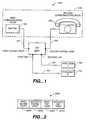
- FIG. 1is a block diagram of a communication system having a full duplex in-line power tap device coupled to a data communication network and analyzers for passing in-line power to the data communication network and for monitoring data signals thereof.
- FIG. 2illustrates a front panel of a full duplex in-line tap power device with four ports: a first signal port, second signal port, a first tap port, and a second tap port.
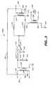
- FIG. 3is a schematic diagram of a first embodiment of the half duplex in-line power tap device.
- FIG. 4is a schematic diagram of a second embodiment of the half duplex in-line power tap device.
- FIG. 5is a schematic diagram of an embodiment of the full-duplex in-line power tap device.
- FIG. 1illustrates a communication system 1000 in which the in-line power tap device 5000 is coupled to a data communication network 100 to monitor data signals and to pass electrical power thereto.
- the system 1000includes a data communication network 100 , the in-line power tap device 5000 , a first analyzer 108 , and a second analyzer 110 coupled to the in-line power tap device 5000 to monitor the data signals and pass in-line power.
- the data communication network 100is well known to a person of ordinary skill in the pertinent art. Examples of the data communication network 100 are Ethernet, local area network (LAN), or an internet system.
- the in-line power tap device 5000is deployed between two communicating nodes of an Ethernet data communication network to monitor data signals and pass along the in-line power.
- the Ethernet data communication network 100includes at least one first communicating node 102 , a plurality of channels 104 , and at least one second communicating node 106 .
- the system 1000 in FIG. 1only shows two communicating nodes of the network 100 because the analysis of these two communicating nodes is sufficient to understand the whole system.
- the first communicating node 102can be a hub or a switching network (switch) such as PBX (personal branch exchange) that connects an incoming signal to a particular destination. It is well known in the data communication art that the first communicating node 102 is represented by one switch as shown in FIG. 1.
- the first communicating node 102has two states of either ON or OFF. When the first communicating node 102 is ON, data signals are transmitted to the second communicating node 106 via the medium 104 . Conversely, when the first communicating node 102 is OFF, no data signal is transmitted.
- the medium 104can be coaxial, unshielded twisted pair (UTP), or shielded twisted pair (STP) cables.
- UTPunshielded twisted pair
- STPshielded twisted pair
- a 10 Base-T cableis commonly used.
- the length of a 10 Base-T cablecan be up to 100 meters from the first communicating node 102 to the second communicating node 106 , and the rate of data transfer is 10 Mbps.
- Faster Ethernet version with a 100 Mbpsuses 100B-X and 100 Base-FX.
- Both 10Base-T and 100Base-TX copper cablescan be either UTP or STP.
- the full duplex in-line power tap device 5000uses UTP cables for both 10 Mbps and 100 Mbps speed, or in short, Ethernet 10/100.
- the second communicating node 106are linked into the first communicating node 102 by four pairs of category 5 cable.
- a category 5 cablehas four unshielded twisted pairs of wires, or a total of 8 wires unshielded twisted-pair cable terminating each end in a RJ-45 much like a telephone jack.
- the second communicating node 106can be a data terminal equipment (DTE) such as a IT telephone, a computer station or a data communicating equipment (DCE) such as, a meter, a switch, or a hub.
- DTEdata terminal equipment
- DCEdata communicating equipment
- the in-line power tap device 5000is a device that provides a way of directly viewing traffic on a full-duplex 10/100 Ethernet segment from the first analyzer 108 and the second analyzer 110 .
- the in-line power tap device 5000is deployed on a critical link between two communicating nodes in the network 100 where network monitoring and analysis are important.
- the first and second analyzers 108 and 110can be coupled to the in-line power tap device 5000 to collect data from any communicating nodes of the data communicating network 100 .
- the propagation of an in-line power between two communicating nodes 102 and 106is performed in accordance with the IEEE 802.3 af which is an Ethernet protocol standard for applying DC power to Ethernet devices via a Medium Dependent Interface (MDI) to guarantee the interoperability between devices.
- MDIMedium Dependent Interface
- FIG. 1shows that the in-line power tap device 5000 can both pass an in-line power to the Ethernet data communication system 100 and monitor the data signals at the same time.
- the in-line power tap device 5000includes four ports: a first signal port 5040 , a second signal port 5030 , a first tap port 5020 , and a second tap port 5010 . All ports, 5040 , 5030 , 5020 , and 5010 , of the device 5000 preferably use a RJ-45 type connector that resembles a telephone connector.
- the RJ-45 type connectoris described in the Ethernet (IEEE 802.3) standard for Local Area Networks (LANs).
- the device 5000is coupled to an Ethernet data communication system 100 between any communicating nodes to pass in-line electrical power, transmit and monitor data signals.
- the in-line power tap device 5000comprises a plurality of signals ports that can be coupled to the first communicating node 102 at the signal port 5040 and to the second communicating node 106 at the second signal port 5030 of the Ethernet data communication network 100 .
- the first signal port 5040 and the second signal port 5030provide means for transmitting data signals between the first communicating node 102 and the second communicating node 106 .
- the first tap port 5020is coupled to the first analyzer 108 and the second tap port 5010 is coupled to the second analyzer 110 for monitoring data signals.
- the power tap device 5000 described aboveis a full-duplex device comprised of two half duplex in-line power tap devices. Each half-duplex device is responsible for one direction of communication.
- the internal structure of a half duplex in-line power tap device 200 ais described in FIG. 3.
- the in-line power tap device 200passes an in-line power between the input and output transformers.
- the first communicating node 102is coupled to the device 200 a at a first signal transformer
- the station 106is coupled to the device 200 at a second signal transformer.
- a power linecoupled to the center taps of the first and second transformers to pass the in-line power between the first communicating node 102 and the second communicating node 106 .
- Data signals of the Ethernet system 100can be monitored at a tap transformer.
- the device 200 acan monitor data signals without taking up a router port and allow an in-line power to pass from the router to network device or any two communicating nodes without interrupting the transmission of data signals.
- the in-line power device 200comprises a first signal port 302 ; a first signal transformer 304 with a primary coil 306 , a center tap 308 , and a secondary coil 309 ; an electrical ground terminal 310 ; an op-amp 312 having a negative input terminal 312 V ⁇ , a positive input terminal 312 V+, and an output terminal 3120 ; an output resistor 340 ; an output resistor 314 ; a tap-port resistor 316 ; a second transformer 318 with a primary coil 320 , a center tap 323 , and a secondary lead 322 ; a tap-port transformer 324 with a primary coil 326 and a secondary coil 328 ; a power line 330 ; a destination port 332 ; and a tap port 334 .
- the in-line power tap device 200monitors the data signal at the tap-port 334 , and passes an in-line power in between both first signal and second signal ports via the power line 330 at the center tap 308 and 323 of the input transformer 304 and the output transformer 318 respectively.
- the first signal transformer 304is a center-tapped transformer having a primary coil 306 for connection to a communicating node of Ethernet data communication system. As described in FIG. 2, either first signal port 210 or second signal port 220 can be coupled to the primary coil 306 of the first signal transformer 304 . One end of the secondary coil is coupled to an electrical ground 310 . The center tap 308 of the first signal transformer 304 is coupled to an the power line 330 . The other end of the secondary coil 309 is coupled to the positive input terminal 312 V+ of the op-amp 312 . One terminal of the input resistor 340 is coupled to the positive input terminal 312 V+ of the op-amp 312 .
- the negative input terminal 312 V ⁇ of the op-amp 312is coupled to the electrical ground 310 .
- the op-amp 312has a gain of 2 or 3 dB.
- the output terminal 3120 of the op-amp 312is coupled to the output resistor 314 and the tap resistor 316 .
- the output 3120 of the op-amp 312is split into two different ports: one port is for the second signal port 332 , and the other is for the tap port 334 .
- the second signal port 332is coupled to the second signal transformer 318
- the tap port 334is coupled to the tap transformer 324 .
- One terminal of the primary coil 320 of the second signal transformer 318is coupled to the output resistor 314 , and the other terminal is coupled to the electrical ground 310 .
- the secondary coil 322 of the transformer 318is coupled to the second signal port 332 .
- the second signal port 332is a two-wired conductor of a RJ-45 type connector.
- One end of the primary coil 326 of the tap transformer 324is coupled to one end of the tap resistor 316 while the other end of the primary coil 326 is grounded.
- the other end of the tap resistor 316is coupled to the output 3120 of the op-amp 312 .
- the secondary coil 328 of the tap transformer 324is coupled to the tap port 334 .
- the in-line poweris passed between to the center taps 208 and 323 of the first signal 302 and second signal port 332 via the power line 330 .
- the first signal port 302is coupled to the first communicating node 102
- the second signal port 332is coupled to the second communicating node 106
- the tap port 334is coupled to the first analyzer 108 .
- the first communicating node 102can also connect to the second signal port 332 and the second communicating node 306 can connect to the first communicating node 102 and the analysis is the same.
- the transformer 304couples the data signal into its secondary coil 309 and feeds it to the positive input terminal 312 V+ of the op-amps amplifier 312 .
- the first signal transformer 302has the primary to secondary ratio (PTSR) of 1. Therefore, at the positive input 312 V+ of the op-amp 312 , the amplitude of the data signal remains the same.
- the data signalis amplified by a factor of 2 because the gain of the op-amp amplifier 312 is set at 3 dB.
- the data signalis split into two signals with the same amplitude, one signal to the second signal port 332 and the other signal to the tap port 334 .
- the data signalis coupled to the secondary coil 322 of the second signal transformer 318 .
- the second signal transformer 318 and the tap port transformer 324both have the PTSR of 1. Because the center tap 322 of the second signal transformer 318 is connected to the power line 330 , the second signal port 332 includes the data signal and the in-line power.
- the half duplex in-line power tap device 200 apasses an in-line power in between two communicating node of the IEEE Ethernet network segment 100 in accordance with the 802.3 af standard.
- data signalscan be monitored without disturbing the data transmission between the first communicating node 102 and the second communicating node 106 .
- the half duplex in-line power tap device 200 apasses the in-line power between the first communicating node 102 and the second communicating node 106 along with the data signal without disturbing the transmission in the medium 104 .
- the data signalcan be monitored independently from the tap port 334 .
- FIG. 4illustrates another embodiment of the present invention.
- This alternative embodiment 200 bis similar to the first embodiment shown in FIG. 3 except that a relay is added to the circuitry of the in-line power device 200 a to allow the communication of data signals continue when the amplifier's power fails.
- a delaywould bypass the amplifier and feed the data signals to the second signal transformer when the amplifier is down. Without this delay, a powerless amplifier would significantly hinder the data transmission of the system 100 . Therefore, a relay would help passing data signals from the first signal port to the second signal port in case the power source of the amplifier fails.
- the relay 340has a power-up state and a power-down state. In the power-up state the relay 340 is connected to the amplifier 312 and behaves exactly as described in FIG. 3 above. However, in the power-down state, the relay 340 bypasses the amplifier and feeds the data signals from the first signal transformer 306 to the second signal transformer. 312 .
- the relay 340comprises two single-pole double-throw switches (SPDT) switches.
- a first SPDT switch 340 S 1includes one input terminal 341 and two output 342 and 343 . The input 341 is connected to the first lead of the secondary coil 309 of the first signal transformer 304 .
- the first output 342is connected to the positive terminal 312 V+ of the op-amp 312 .
- the second SPDT switch 340 S 2includes an input 344 coupled to the primary coil of 320 of the second signal transformer 318 , a first output 345 coupled to the second terminal of the signal resistor 314 .
- the second output 343 of the first SPDT switch 340 S 1is connected to a second output terminal 346 of the second switch 340 S 2 .
- the switching of the relay 340is controlled by the power source of the amplifier 312 .
- the first SPDT switch 340 S 1 and the second SPDT switch 340 S 2switch to their first output terminal positions 342 and 345 respectively, connecting to amplifier 312 to the first signal port 302 and the second signal port 332 and the device 200 b works similarly to the device 200 a described in FIG. 3.
- the first SPDT switch 340 S 1 and the second SPDT switch 340 S 2switch to their second output terminal positions 343 and 346 respectively, bypassing the failed amplifier 312 .
- the relay 340connects the first signal port 302 directly to the second signal port 332 .
- the device 200 bhas a relay so that it can be set to bypass the op-amp in the event that the power source of the op-amp fails. Thus, the device 200 b always operates even when the power to the amplifier 312 fails.
- the relaycan be omitted.
- FIG. 5illustrates a detailed schematic diagram of an in-line power tap device having two channels for monitoring an Ethernet data communication network.
- the two-channel in-line power tap device 5000works similar to the combination of the one-channel device 200 b, as described in FIG. 4 above.
- Each device 200 bis communicating with the system 100 in one direction.
- the data communication from the first communicating node 102 to the second communicating node 106 as shown in FIG. 4is exactly the same as that from the second communicating node 106 to the first communicating node 102 .
- a in-line poweris passed along a power line between two communicating nodes of the full duplex Ethernet data communication network; whereas the data signals are transmitted between two communicating nodes and are monitored separately at the tap ports.
- the duplex in-line power tap device 5000comprises two one-channel in-line power tap devices with the relay option 200 b put together in opposite direction.
- the in-line power tap device 5000always communicating works in full duplex communication: in a TRANS+/RECEIV+, the first node transmits the second node receives. In the TRANS ⁇ /RECEIV ⁇ communicating, the communication is in the opposite direction from the second node to the first node.
- the full duplex in-line power tap device 5000comprises a first signal port 5040 , a second signal port 5030 , a first tap port 5020 , a second tap port 5010 , first signal transformer 5100 , second signal transformer 5200 , a first tap-transformer 5300 , a second tap-transformer 5400 , a first relay 5500 , a second relay 5600 , a first op-amp 5700 , a second op-amp 5800 , an electrical ground 5900 , a in-line power line 5930 , and a power source 5940 for the op-amps and the relays.
- the first signal port 5040is the IEEE 802.3 standard-type connector with 8 pins: pins 5041 through 5048 .
- the pin 5047is connected to pin 5048 and to the DC electrical power line 5930 .
- the pin 5044is connected to pin 5045 .
- the electrical ground 5900is preferably coupled to the chassis of the in-line power tap device 5000 .
- the second signal port 5030comprises 8 pins 5031 to 5038 and has the same connection configuration among pins as the first signal port 5040 .
- Pin 5037is connected to pin 5038 and to the DC electrical power line 5930 .
- the power line 5930is preferably a power trace in a printed circuit board (PCB) connecting the first signal port 5040 , the second signal port 5030 .
- the pin 5034is connected to pin 5035 .
- the first tap port 5020is also an IEEE 802.3 RJ-45 type connector with 8 pins: pins 5021 through 5028 .
- the pin 5027is connected to pin 5028 and to the electrical ground 5900 .
- Pin 5024is connected to pin 5025 .
- the second tap port 5010comprises 8 pins 5011 to 5018 and has the same connection configuration among pins as the tap port A 5020 .
- the pin 5017is connected to pin 5018 and to the electrical ground 5900 .
- Pin 5014is connected to pin 5015 .
- the first signal transformer 5100is an IC type transformer that has 24 pins and contains four center-tapped transformers 5100 A, 5100 B, 5100 C, and 5100 D, respectively.
- the pin-out arrangement of the first signal transformer 5100is as follows: each center-tapped transformer occupies 6 pins out of the 24 pins of the transformer A 5100 .
- the first transformer 5100 Ahas a primary coil 5100 AP and a secondary coil 5100 AS.
- the primary coil 5100 APincludes a top pin 5124 , a center-tapped pin 5123 , and a bottom pin 5122 .
- the secondary 5100 ASincludes a top pin 5101 , a center-tapped pin 5102 , and a bottom pin 5103 .
- the second transformer 5100 B of the first signal transformer 5100has a primary coil 5100 BP and a secondary coil 5100 BS.
- the primary 5100 BPincludes a top pin 5121 , a center-tapped pin 5120 , and a bottom pin 5119 .
- the secondary coil 5100 BSincludes a top pin 5104 , a center-tapped pin 5105 , and a bottom pin 5106 .
- the transformer 5100 C of the input transformer A 5100has a primary coil 5100 CP and a secondary coil 5100 CS.
- the primary coil 5100 CPincludes a top pin 5118 , a center-tapped pin 5117 , and a bottom pin 5116 .
- the secondary coil 5100 CSincludes a top pin 5107 , a center-tapped pin 5108 , and a bottom pin 5109 .
- the fourth transformer 5100 D of the first signal transformer 5100has a primary coil 5100 DP and a secondary coil 5100 DS.
- the primary coil 510 ODPincludes a top pin 5115 , a center-tapped pin 5114 , and a bottom pin 5113 .
- the secondary 5100 DSincludes a top pin 5110 , a center-tapped pin 5111 , and a bottom pin 5112 .
- the primary coil of the first transformer 5100 AP, the primary coil of the second transformer 5100 BP, and the secondary coil of the second transformer 5100 CSare coupled together to form a center-tapped transformer with the PTSR of 1:1 in the following manner: the bottom pin 5122 of the first transformer 5100 A is coupled to the center-tapped pin 5120 of the second transformer 5100 B.
- the top pin 5104 of the secondary 5100 BS of the second transformer 5100 Bis coupled to the electrical ground 5900 .
- the top pin 5121 of the primary 5100 BP of the first transformer 5100 Bis coupled to pin 5046 of the first signal connector 5040
- the bottom pin 5119 of the primary coil 5100 BPis coupled to pin 5043 of the first signal connector 5040 .
- the primary coil of the third transformer 5100 CP, the primary coil of the fourth transformer 5100 DP, and the secondary coil of the fourth transformer 5100 CSare coupled together to form a center-tapped transformer with the PTSR of 1:1 in the following manner: the top pin 5115 of the fourth transformer 5100 D is coupled to the center-tapped pin 5117 of the third transformer 5100 C.
- the top pin 5107 of the secondary 5100 CS of the third transformer 5100 Cis coupled to the electrical ground 5900 .
- the top pin 5118 of the primary coil 5100 CP of the third transformer 5100 Cis coupled to pin 5042 of the first signal 5040
- the bottom pin 5116 of the primary coil 5100 CPis coupled to pin 5041 of the first signal 5040 .
- the second signal transformer 5200is an IC type transformer that has 24 pins and contains four center-tapped transformers 5200 A, 5200 B, 5200 C, and 5200 D, respectively.
- the pin-out of the transformer B 5200is as follows: each center-tapped transformer occupies 6 pins out of the 24 pins of the second signal transformer 5200 .
- the first transformer 5200 Ahas a primary coil 5200 AP and a secondary coil 5200 AS.
- the primary coil 5200 APincludes a top pin 5224 , a center-tapped pin 5223 , and a bottom pin 5222 .
- the secondary coil 5200 ASincludes a top pin 5201 , a center-tapped pin 5202 , and a bottom pin 5203 .
- the second transformer 5200 B of the second signal transformer 5200has a primary coil 5200 BP and a secondary coil 5200 BS.
- the primary coil 5200 BPincludes a top pin 5221 , a center-tapped pin 5220 , and a bottom pin 5219 .
- the secondary coil 5200 BSincludes a top pin 5204 , a center-tapped pin 5205 , and a bottom pin 5206 .
- the transformer 5200 C of the second signal transformer 5200has a primary coil 5200 CP and a secondary 5200 CS.
- the primary coil 5200 CPincludes a top pin 5218 , a center-tapped pin 5217 , and a bottom pin 5216 .
- the secondary coil 5200 CSincludes a top pin 5207 , a center-tapped pin 5208 , and a bottom pin 5209 .
- the fourth transformer 5200 D of the second signal transformer B 5100has a primary coil 5200 DP and a secondary coil 5200 DS.
- the primary coil 5200 DPincludes a top pin 5215 , a center-tapped pin 5214 , and a bottom pin 5213 .
- the secondary coil 5200 DSincludes a top pin 5210 , a center-tapped pin 5211 , and a bottom pin 5212 .
- the primary coil of the first transformer 5200 AP, the primary coil of the second transformer 5200 BP, and the secondary coil of the second transformer 5200 CSare coupled together to form a center-tapped transformer with the PTSR of 1:1 in the following manner: the bottom pin 5222 of the first transformer 5200 A is coupled to the center-tapped pin 5220 of the second transformer 5200 B.
- the top pin 5204 of the secondary coil 5200 BS of the second transformer 5200 Bis coupled to the electrical ground 5900 .
- the top pin 5221 of the primary coil 5200 BP of the first transformer 5200 Bis coupled to pin 5036 of the second signal port 5030
- the bottom pin 5219 of the primary coil 5200 BPis coupled to pin 5033 of the second signal connector 5030 .
- the primary coil of the third transformer 5200 CP, the primary coil of the fourth transformer 5200 DP, and the secondary coil of the fourth transformer 5200 CSare coupled together to form a center-tapped transformer with the PTSR of 1:1 in the following manner: the top pin 5215 of the fourth transformer 5200 D is coupled to the center-tapped pin 5217 of the third transformer 5200 C.
- the top pin 5207 of the secondary coil 5200 CS of the third transformer 5200 Cis coupled to the electrical ground 5900 .
- the top pin 5218 of the primary 5200 CP of the third transformer 5200 Cis coupled to pin 5032 of the input A 5030
- the bottom pin 5216 of the primary 5200 CPis coupled to pin 5031 of the input A 5030
- the DC electrical power 5930connects the top pin 5124 to the first signal transformer 5100 to he top pin 5224 of the second signal transformer 5200
- the DC electrical power 5930also connects the bottom pin 5113 and the first signal transformer 5100 to the bottom pin 5213 of the second signal transformer 5200 .
- the first tap transformer 5300is also an IC type transformer that has 24 pins and contains four center-tapped transformers 5300 A, 5300 B, 5300 C, and 5300 D, respectively.
- the pin-out of the first transformer 5300is as follows: each center-tapped transformer occupies 6 pins out of the 24 pins of the tap-transformer B 5300 .
- the first transformer 5300 Ahas a primary coil 5300 AP and a secondary coil 5300 AS.
- the primary 5300 APincludes a top pin 5324 , a center-tapped pin 5323 , and a bottom pin 5322 .
- the secondary coil 5300 ASincludes a top pin 5301 , a center-tapped pin 5302 , and a bottom pin 5303 .
- the second transformer 5300 B of the tap-transformer B 5300has a primary coil 5300 BP and a secondary coil 5300 BS.
- the primary coil 5300 BPincludes a top pin 5321 , a center-tapped pin 5320 , and a bottom pin 5319 .
- the secondary 5300 BSincludes a top pin 5304 , a center-tapped pin 5305 , and a bottom pin 5306 .
- the transformer 5300 C of the tap-transformer B 5300has a primary coil 5300 CA and a secondary coil 5300 CS.
- the primary coil 5300 CPincludes a top pin 5318 , a center tap pin 5317 , and a bottom pin 5316 .
- the secondary coil 5300 CSincludes a top pin 5307 , a center-tapped pin 5308 , and a bottom pin 5309 .
- the fourth transformer 5300 D of the tap-transformer B 5300has a primary coil 5300 DP and a secondary coil 5300 DS.
- the primary 5300 DPincludes a top pin 5315 , a center-tapped pin 5314 , and a bottom pin 5313 .
- the secondary coil 5300 DSincludes a top pin 5310 , a center tap pin 5311 , and a bottom pin 5312 .
- the top pin 5321 of the primary coil 5300 BP of the second transformer 5300 Bis coupled to pin 5026 of the second tap port 5020 .
- the center-tapped pin 5320 of the same transformeris coupled to pin 5025 and 5024 of the first tap port 5020 ; and the bottom pin 5319 is connected to pin 5023 of the first tap port 5020 .
- the top pin 5318 and the bottom pin 5316 of the third transformer 5300 CPare connected to pin 5022 and 5021 respectively.
- the center-tapped pin 5317is coupled to the electrical ground 5900 .
- the top pin 5304 of the second transformer 5300 BSis coupled to the electrical ground 5900 .
- the second transformer 5300 Bhas the PTSR of 1:1.
- the second tap transformer 5400is also an IC type transformer that has 24 pins and contains four center-tapped transformers 5400 A, 5400 B, 5400 C, and 5400 D, respectively.
- the pin-out of the first tap transformer 5400is as follows: each center-tapped transformer occupies 6 pins out of the 24 pins of the transformer D 5400 .
- the first transformer 5400 Ahas a primary coil 5400 AP and a secondary coil 5400 AS.
- the primary coil 5400 APincludes a top pin 5424 , a center-tapped pin 5423 , and a bottom pin 5422 .
- the secondary coil 5400 ASincludes a top pin 5401 , a center-tapped pin 5402 , and a bottom pin 5403 .
- the second transformer 5400 B of the second tap transformer 5400has a primary coil 5400 BP and a secondary coil 5400 BS.
- the primary coil 5400 BPincludes a top pin 5421 , a center-tapped pin 5420 , and a bottom pin 5419 .
- the secondary coil 5400 BSincludes a top pin 5404 , a center-tapped pin 5405 , and a bottom pin 5406 .
- the transformer 5400 C of the second tap transformer 5400has a primary 5400 CP and a secondary 5400 CS.
- the primary coil 5400 CPincludes a top pin 5418 , a center-tapped pin 5417 , and a bottom pin 5416 .
- the secondary coil 5400 CSincludes a top pin 5407 , a center-tapped pin 5408 , and a bottom pin 5409 .
- the fourth transformer 5400 D of the second tap transformer 5400has a primary coil 5400 DP and a secondary coil 5400 DS.
- the primary coil 5400 DPincludes a top pin 5415 , a center-tapped pin 5414 , and a bottom pin 5413 .
- the secondary 5400 DSincludes a top pin 5410 , a center-tapped pin 5411 , and a bottom pin 5412 .
- the top pin 5421 of the primary coil 5400 BP of the second transformer 5400 Bis coupled to pin 5016 of the second tap port 5010 .
- the center tap pin 5420 of the same transformeris coupled to pin 5015 and 5014 of the second tap port 5010 ; and the bottom pin 5419 is connected to pin 5013 of the second tap port 5010 .
- the top pin 5418 and the bottom pin 5416 of the third transformer 5400 CPare connected to pin 5012 and 5011 respectively.
- the center-tapped pin 5417is coupled to the electrical ground 5900 .
- the top pin 5404 of the second transformer 5400 BSis coupled to the electrical ground 5900 .
- the second transformer 5400 Bhas the PTSR of 1:1.
- the first relay 5500 and the second relay 5600are of the same type. Each relay has two single-pole double-throw (SPDT) switches with two input terminals and 4 output terminals as described in FIG. 4. Terminals 3 and 8 are two input terminals and 2 , 4 , 7 , and 9 are output terminals.
- the first relay 5500has two input terminals 5503 and 5508 with four output terminals 5502 , 5504 , 5507 , and 5509 .
- the input terminal 5503switches between the output 5502 and 5504 ; while the input terminal 5508 switches between the output 5507 and 5509 .
- the second relay 5600has two input terminals 5603 and 5608 with four output terminals 5602 , 5604 , 5607 , and 5609 .
- the input terminal 5603switches between the output 5602 and 5604 ; while the input terminal 5608 switches between the output 5607 and 5609 .
- the input terminal 5503 of the first relay 5500is coupled to the bottom pin 5109 of the secondary coil of the third transformer 5100 CS, and the input terminal 5508 is coupled to the bottom pin 5209 of the secondary coil 5200 CS of the third transformer 5200 C of the second signal transformer 5200 .
- the output pins 5502 , 5504 , and 5509are coupled together and to a first terminal 5530 A of the resistor 5530 .
- a second terminal 5530 B of the resistor 5530is coupled to the electrical ground 5900 .
- the input terminal 5503has only one value regardless of what output it switches to because the output pins 5502 is coupled to the output terminals 5504 , and 5509 .
- the input terminal 5603 of the second relay 5600is coupled to the bottom pin 5206 of the secondary coil of the second transformer 5200 BS, and the input pin 5608 is coupled to the bottom pin 5106 of the secondary coil 5100 BS of the second transformer 5100 B of the first signal transformer 5100 .
- the output terminals 5602 , 5604 , and 5609are coupled together and to a first terminal 5630 A of the resistor 5630 .
- a second terminal 5630 B of the resistor 5630is coupled to the electrical ground 5900 .
- the input terminal 5603has only one value regardless of what output it switches to because the output pins 5602 is coupled to the output pin 5604 , and pin 5609 .
- Both first and second relays 5500 and 5600are controlled by a second power 5940 .
- the first relay 550 and the second relay 5600switch to bypass the op-amp 5700 and 5800 .
- the power 5940is up the first and second relays 5500 and 5600 respectively, switch to connect the op-amps.
- the op-amps 5700 and 5800each is an 8-pin IC.
- the VIN ⁇is pin 2 and the VIN+ is pin 3 .
- the output VOis pin 8 .
- the power supplyis pin 7 and the ground is pin 1 .
- the op-amp 5700has a negative input terminal VIN ⁇ 5702 , and a positive input terminal VIN+ 5703 , and an output terminal VO 5706 .
- the op-amp 5800has an input terminal VIN ⁇ 5802 , a positive input terminal VIN+ 5803 , and an output terminal VO 5806 .
- Both negative input terminals 5702 and 5802are coupled to the electrical ground 5900 .
- Both power supply pins 5707 and 5807are coupled to the second power 5940 of 10 VDC.
- the positive input terminal VIN+ 5703 of the op-amp 5700is coupled to the output pins 5502 , 5504 and 5509 of the relay D 3 5500 and to the first terminal 5530 A of the resistor 5530 .
- the output pin 5507 of the relay D 3 5500is coupled to a first terminal 5710 A of the resistor 5710 ;
- a second terminal 5710 B of the resistor 5710is coupled to the output pin VO 5706 of the op-amp 5700 and to a first terminal 5720 A of the resistor 5720 .
- a second terminal 5720 B of the resistor 5720is coupled to the bottom pin 5306 of the secondary 5300 BS of the second transformer 5300 B of the second tap transformer 5300 .
- the positive terminal VIN+ 5803 of the op-amp 5800is coupled to the output pins 5602 , 5604 , and 5609 of the relay D 4 5600 and to the first terminal 5630 A of the resistor 5630 .
- the output pin 5607 of the relay D 4 5600is coupled to a first terminal 5810 B of a resistor 5810 ;
- a second terminal 5810 A of the resistor 5810is coupled to the output pin 5806 of the op-amp 5800 and to a first terminal 5820 A of a resistor 5820 .
- a second terminal 5820 B of the resistor 5820is coupled to the bottom pin 5406 of the secondary coil 5400 BS of the second transformer 5400 B of the first tap transformer 5400 .
- pins 5041 and 5042 of the first signal port 5040are transmitted signals from the first node 102 to the second node 106 , or TRANS+ data signal; and, pins 5031 and 5032 of the second signal port 5030 are received data signals at the second node 106 , or RECEIV+ data signal.
- Pins 5033 , and 5036 of the second signal port 5030transmit signals from the opposite direction from the second communicating node 106 to the first communicating node 102 , or TRANS ⁇ data signal; whereas pins 5043 , 5046 of the first signal port 5040 are received signals, or RECEIV ⁇ data signal.
- the signal transformer pairs 5100 B and 5100 Ccouple the TRANS+ data signal at the top pin 5121 into the primary coil at pins 5116 and 5118 . While the in-line power is passed from the first signal port 5040 to the second signal port 5030 via the power line 5930 connecting pin 5113 to pin 5213 .
- the data signal TRANS+ at pin 5109is same as that of the original TRANS+ signal because the primary to secondary ratio is 1:1.
- the TRANS+ data signal of the same amplitudeis then fed to the input port 5503 of the first relay 5500 .
- RECEIV+ data signalsare observed at pins 5031 and 5032 of the second signal port 5030 .
- This RECEIV + data signalis coupled to the third transformer 5200 C.
- the RECEIV+ data signal's amplituderemains the same because the PTSR of the third and fourth transformer 5200 C and 5200 D is 1:1.
- RECEIV+ data signalsare fed to the input port 5508 of the first relay 5500 .
- both first and second relays 5500 and 5600are controlled by a second power 5940 .
- the first relay 550 and the second relay 5600switch to bypass the op-amps 5700 and 5800 .
- the power 5940is up the first and second relays 5500 and 5600 respectively, switch to connect the op-amps.
- the input terminal 5508is switched to the output 5509 and the input terminal 5503 is switched to the position pin 5504 . Therefore, both TRANS+/RECEIV+ data signals appear at the positive input VIN+ 5703 of the op-amp 5700 . Because the gain of the op-amp 5700 is set at 2, the output data signals TRANS+/RECEIV+ signals at the output terminal 5706 of the op-amp 5700 are now twice their original values.
- the TRANS+/RECEIV+ data signals at the second terminals of the resistors 5710 and 5720are restored to their original amplitude.
- the TRANS+/RECEIV+ data signalsare received at pin 5306 of the secondary coil 5300 BS and coupled to the primary coil 5300 BP of the second tap transformer 5300 at pins 5319 , 5320 and 5321 .
- the primary to secondary ratio of the second transformer 5300is 1:1, the TRANS+/RECEIV+ data signals at pins 5321 and 5319 are at the same amplitude as the original signal data.
- the second tap transformersplits the TRANS+/RECEIV+ signals at pin 5023 and pin 5026 .
- the TRANS+ data signals at the first communicating node 102can be monitored at pin 5023
- the RECEIV+ signals at the second communicating node 106can be monitored at pin 5026 or vice versa.
- the input 5508is switched to the output 5507 of the first relay 5500 , and, the first 5503 switches to 5502 , thus bypassing the op-amp 5700 .
- the first relay 5500guarantees that the TRANS+/RECEIV+ signals always passed through from the first communicating node 102 to the second communicating node 106 and vice versa.
- pins 5033 and 5036 of the second signal port 5030are TRANS ⁇ data signals
- pins 5043 , 5046 of the input port 5040are RECEIV ⁇ data signal.
- the TRANS ⁇ data signalis coupled to pins 5219 and 5220 of the primary coil 5100 BP and appears at pin 5206 of the second transformer 5200 B of the transformer 5200 . Again, because the primary to secondary ratio of this transformer is 1:1, the output TRANS ⁇ at pin 5206 is equal in amplitude.
- the in-line poweris passed from the first signal connector 5040 to the second signal connector 5030 by the power line 5930 connecting pin 5124 the first signal transformer 5100 to the pin 5224 of the second signal transformer 5200 .
- the RECEIV ⁇ data signalappears at pin 5106 of the second transformer 5100 BS.
- the TRANS ⁇ data signalis coupled to the input pin 5603 and the RECEIV ⁇ data signal is coupled to the input terminal 5608 of the second relay 5600 .
- the input 5608is switched to the output 5609 or the positive terminal VIN+ 5803 of the op-amp 5800 .
- the input 5603is also switched to the positive terminal VIN+ 5802 so that the TRANS ⁇ and RECEIV ⁇ signals are input to the op-amp 5800 .
- the TRANS ⁇ /RECEIV ⁇ signalsare amplified by 3 dB.
- TRANS ⁇ and RECEIV ⁇ data signalsare restored to their original values of the second terminal 5820 B of the resistor 5820 and coupled to the second tap-transformer 5400 via the secondary coil 5400 BS of the second transformer 5400 B.
- the TRANS ⁇ and RECEIV ⁇ data signalscan be monitored at pins 5012 and 5016 of the second tap port 5010 .
- the second relay 5600guarantees the TRANS ⁇ /RECEIV ⁇ signals are always passed through the device 200 from the first communicating node 102 to the second communicating node 106 .
Landscapes
- Engineering & Computer Science (AREA)
- Computer Networks & Wireless Communication (AREA)
- Signal Processing (AREA)
- Power Engineering (AREA)
- Cable Transmission Systems, Equalization Of Radio And Reduction Of Echo (AREA)
Abstract
Description
- This application claims the benefit of two prior filed provisional applications: provisional application Serial No. 60/287,833, filed on Apr. 30, 2001 and provisional application Serial No. 60/288,981, filed on May 3, 2001.[0001]
- This invention broadly relates to data communication. More particularly, the invention relates to an apparatus that passes electrical power and monitors data signals of a data communication network.[0002]
- The explosive growth of the Internet, E-commerce, business critical network applications, and the convergence of voice, video and data, has made network performance and reliability central to the successes of most companies. Many companies today transmit and receive important data signals over the Ethernet data communication networks. An Ethernet communication network comprises a hub or PBX (private branch exchange) coupled to a channel and to many stations. The PBX receives data signals from stations and connects stations that are in communication with one another. Usually, in an Ethernet data communication network, backup electrical power is provided at each network center, but not at each local station because the cost to provide backup electrical power at each station is prohibitive. When companies are in the process of communicating to one another, power failure or even a brief power blackout would cause loss of critical information and great damage. Ethernet data communication networks follow the IEEE 802.3 standard in which electrical power is provided in-line with the data signals. The IEEE 802.3 standard requires that the Ethernet data communication networks use UTP (unshielded twisted pair) cables to transport data signals and electrical power together to provide power and data signals to each station. A similar arrangement exists for telephone loops from a central office.[0003]
- To guarantee the reliability and quality of the data signals in an IEEE 802.3 af UTP Ethernet data communications link, engineers and technicians need to monitor the data signals and the electrical power of each communication port without disturbing the ongoing communication process of that port. To achieve that goal, engineers and technicians have to disconnect a port and insert in its place a measuring instrument to monitor the quality and reliability of that particular port, thus interrupting the communication process of that port. In addition, when a channel port is disconnected, electrical power to the station is also disconnected.[0004]
- Therefore, there is a need for an apparatus that can provide electrical power to Ethernet data communication networks and to monitor the data signal quality of such networks without disturbing the communication process between stations.[0005]
- There have been many attempts to solve and improve in-line power for signal activities for Ethernet data communication links, but none provides both the in-line power and monitoring signals at the same time without disturbing the communication process. In the U.S. Pat. No. 6,115,468 entitled “Power Feed for Ethernet Telephones Via Ethernet Link” by Maurillio Tazio De Dicolo (hereinafter ‘468 patent’), the inventor discloses an Ethernet device power transmission system that includes an input transformer, an output transformer, and a pair of twisted pair conductors. The input transformer includes a pair of primary windings for connection to a source Ethernet data, and a pair of secondary windings for connection to the Ethernet telephone line. Each transformer has a center tap. A first twisted pair conductor is connected across the first secondary, a second twisted pair conductor is connected across the second secondary and a DC-bias is provided between respective center taps of the first and second secondary. At the local end, an output transformer includes a first and a second center-tapped primary and a first and secondary connection to the load device. The first and second primary center taps are connected to a power processor for extraction of DC power. The '468 patent provides DC electrical power to the Ethernet line and overcomes the problem of net current flow that limits the choice of wire gauge. In this invention, the power is split into separate transmitting and receiving lines; and therefore, the power delivered to the load device is split equally over four wires. However, the invention in '468 patent does not monitor signal activities at the port; it only provides power for Ethernet telephones via an Ethernet link. In addition, each load of the apparatus described in the '468 patent needs a separate power processor, making this invention bulky and expensive.[0006]
- Another attempt to solve signal monitoring and electrical power supply problems in an Ethernet data communication system is provided by U.S. Pat. No. 6,218,930 entitled “Apparatus and Method for Remotely Powering Access Equipment Over a 10/100 Switched Ethernet Network” by Boris Katzenberg, and Joseph A. Deptulla, (hereinafter '930 patent). The invention described in the '930 patent discloses an apparatus and method for remotely powering access equipment over a 10/100 switched Ethernet network comprising an Ethernet switch card with a phantom power supply for remote access equipment and added circuitry for automatic detection of remote equipment being connected to the network. The apparatus described in the '930 patent can only sense whether there is a remote apparatus connected to the system and provides a phantom power supply thereto. However, it cannot monitor the consistency of the power supply of a remote device and signal activities of a port. In other words, once the apparatus of the '930 patent detects a remote device and provides phantom power thereto, it cannot monitor whether there is a temporary power surge or not. When the power surge is sufficiently large, the apparatus of the '930 patent may mistakenly determine that the device has been disconnected and cut off the power to it. This may damage the remote device and cause a loss of critical signals. Finally, the apparatus of the '930 patent cannot monitor the data signals and the electrical power supply of the remote station.[0007]
- Yet another attempt to solve the signal monitoring and electrical power supply problem for the Ethernet data communication system is found in the U.S. Pat. No. 6,140,911 entitled “Power Transfer Apparatus for Concurrently Transmitting Data and Power Over Data Wires” by David A. Fisher (hereinafter '911 patent). This invention provides an electric power supply to a network device across a transmission line. The patent discloses use of an electrical supply current sufficient to power a wireless access point. Power is transmitted concurrently with a network data signal across a transmission line. A power and data coupler couples the network data input and a power input respectively, and transmits the coupled signal, to a distance of three meters or more, over the transmission line to a power and data coupler. The power and data decoupler separates the power signal from the network data signal and supplies those signals to a power output port and a data output port, respectively, for use by a wireless access node. The power signal may be modulated at a low frequency relative to the frequency of the data signal. The electrical supply current of the invention described in the '911 patent does not tap into an in-line power supply to monitor and maintain a constant electrical power supply.[0008]
- In conclusion, prior art technologies have improved in-line power supply problems. However, the prior art does not provide both an in-line DC electrical power supply to the Ethernet communication network and a monitor for data signals at the same time without disturbing the communication process. Accordingly, it is the object of the present invention to provide an apparatus that can provide both an in-line power supply and a monitor for data signals of an Ethernet data communication network without disturbing the communication process of such system.[0009]
- The above object has been achieved by an in-line power tap device for monitoring data signals and allowing DC electrical power to go through a data communication network uninterrupted. The in-line power tap device comprises a plurality of signal ports coupled to communicating nodes of the data communication network, at least one tap port coupled to a plurality of signal ports for monitoring data signals, means for transmitting the data signals, and means for passing the DC power between signal ports. The data signals are transmitted between the pins of the plurality of the signal ports and monitored on the pins of at least one tap port, and the DC power is passed through on a separate power line between the plurality of the signal ports inside a tap port. In one embodiment of the present invention, the means for transmitting the data signals comprises a plurality of input transformers, a plurality of amplifiers, a plurality of output transformers, and a plurality of tap transformers.[0010]
- In another embodiment of the invention, the means for transmitting the data signals includes a plurality of relays coupled to input transformers. The input transformers are coupled to a plurality of amplifiers, which are coupled to a plurality of output transformers to transmit data signals in a network. The device also monitors data signals without disturbing the in-line power transmission and maintains the integrity of the signal data transmitted.[0011]
- FIG. 1 is a block diagram of a communication system having a full duplex in-line power tap device coupled to a data communication network and analyzers for passing in-line power to the data communication network and for monitoring data signals thereof.[0012]
- FIG. 2 illustrates a front panel of a full duplex in-line tap power device with four ports: a first signal port, second signal port, a first tap port, and a second tap port.[0013]
- FIG. 3 is a schematic diagram of a first embodiment of the half duplex in-line power tap device.[0014]
- FIG. 4 is a schematic diagram of a second embodiment of the half duplex in-line power tap device.[0015]
- FIG. 5, consisting of FIGS. 5A and 5B, is a schematic diagram of an embodiment of the full-duplex in-line power tap device.[0016]
- FIG. 1 illustrates a[0017]
communication system 1000 in which the in-linepower tap device 5000 is coupled to adata communication network 100 to monitor data signals and to pass electrical power thereto. Thesystem 1000 includes adata communication network 100, the in-linepower tap device 5000, afirst analyzer 108, and asecond analyzer 110 coupled to the in-linepower tap device 5000 to monitor the data signals and pass in-line power. Thedata communication network 100 is well known to a person of ordinary skill in the pertinent art. Examples of thedata communication network 100 are Ethernet, local area network (LAN), or an internet system. The in-linepower tap device 5000 is deployed between two communicating nodes of an Ethernet data communication network to monitor data signals and pass along the in-line power. Generally, the Ethernetdata communication network 100 includes at least one first communicatingnode 102, a plurality ofchannels 104, and at least one second communicatingnode 106. Thesystem 1000 in FIG. 1 only shows two communicating nodes of thenetwork 100 because the analysis of these two communicating nodes is sufficient to understand the whole system. In an Ethernet data communication network, the first communicatingnode 102 can be a hub or a switching network (switch) such as PBX (personal branch exchange) that connects an incoming signal to a particular destination. It is well known in the data communication art that the first communicatingnode 102 is represented by one switch as shown in FIG. 1. The first communicatingnode 102 has two states of either ON or OFF. When the first communicatingnode 102 is ON, data signals are transmitted to the second communicatingnode 106 via the medium104. Conversely, when the first communicatingnode 102 is OFF, no data signal is transmitted. - The medium[0018]104 can be coaxial, unshielded twisted pair (UTP), or shielded twisted pair (STP) cables. In an Ethernet data communication, a 10 Base-T cable is commonly used. Typically, the length of a 10 Base-T cable can be up to 100 meters from the first communicating
node 102 to the second communicatingnode 106, and the rate of data transfer is 10 Mbps. Faster Ethernet version with a 100 Mbps uses 100B-X and 100 Base-FX. Both 10Base-T and 100Base-TX copper cables can be either UTP or STP. In the preferred embodiment, the full duplex in-linepower tap device 5000 uses UTP cables for both 10 Mbps and 100 Mbps speed, or in short, Ethernet 10/100. In a typical Ethernet data communication, the second communicatingnode 106 are linked into the first communicatingnode 102 by four pairs of category 5 cable. As discussed above, a category5 cable has four unshielded twisted pairs of wires, or a total of 8 wires unshielded twisted-pair cable terminating each end in a RJ-45 much like a telephone jack. - The second communicating[0019]
node 106 can be a data terminal equipment (DTE) such as a IT telephone, a computer station or a data communicating equipment (DCE) such as, a meter, a switch, or a hub. - The in-line[0020]
power tap device 5000 is a device that provides a way of directly viewing traffic on a full-duplex 10/100 Ethernet segment from thefirst analyzer 108 and thesecond analyzer 110. Typically, the in-linepower tap device 5000 is deployed on a critical link between two communicating nodes in thenetwork 100 where network monitoring and analysis are important. - In a multi-channel Ethernet data communication system, the first and[0021]
second analyzers power tap device 5000 to collect data from any communicating nodes of thedata communicating network 100. The propagation of an in-line power between two communicatingnodes - Therefore, FIG. 1 shows that the in-line[0022]
power tap device 5000 can both pass an in-line power to the Ethernetdata communication system 100 and monitor the data signals at the same time. - With reference to FIG. 2, the in-line[0023]
power tap device 5000 includes four ports: afirst signal port 5040, asecond signal port 5030, afirst tap port 5020, and asecond tap port 5010. All ports,5040,5030,5020, and5010, of thedevice 5000 preferably use a RJ-45 type connector that resembles a telephone connector. The RJ-45 type connector is described in the Ethernet (IEEE 802.3) standard for Local Area Networks (LANs). Thedevice 5000 is coupled to an Ethernetdata communication system 100 between any communicating nodes to pass in-line electrical power, transmit and monitor data signals. The in-linepower tap device 5000 comprises a plurality of signals ports that can be coupled to the first communicatingnode 102 at thesignal port 5040 and to the second communicatingnode 106 at thesecond signal port 5030 of the Ethernetdata communication network 100. Thefirst signal port 5040 and thesecond signal port 5030 provide means for transmitting data signals between the first communicatingnode 102 and the second communicatingnode 106. Thefirst tap port 5020 is coupled to thefirst analyzer 108 and thesecond tap port 5010 is coupled to thesecond analyzer 110 for monitoring data signals. Conversely, thefirst signal port 5040 of the in-line power 5000 can also connect to the second communicatingnode 106, and thesecond signal port 5030 can connect to the first communicatingnode 102 but the wiring within the connector RJ-45 has to be changed accordingly. Thepower tap device 5000 described above is a full-duplex device comprised of two half duplex in-line power tap devices. Each half-duplex device is responsible for one direction of communication. The internal structure of a half duplex in-linepower tap device 200ais described in FIG. 3. - With reference to FIG. 3, the in-line power tap device[0024]200 passes an in-line power between the input and output transformers. The first communicating
node 102 is coupled to thedevice 200aat a first signal transformer, and thestation 106 is coupled to the device200 at a second signal transformer. A power line coupled to the center taps of the first and second transformers to pass the in-line power between the first communicatingnode 102 and the second communicatingnode 106. Data signals of theEthernet system 100 can be monitored at a tap transformer. With this arrangement thedevice 200acan monitor data signals without taking up a router port and allow an in-line power to pass from the router to network device or any two communicating nodes without interrupting the transmission of data signals. - The in-line power device[0025]200 comprises a
first signal port 302; afirst signal transformer 304 with aprimary coil 306, acenter tap 308, and asecondary coil 309; anelectrical ground terminal 310; an op-amp 312 having anegative input terminal 312V−, a positive input terminal312V+, and anoutput terminal 3120; anoutput resistor 340; anoutput resistor 314; a tap-port resistor 316; asecond transformer 318 with aprimary coil 320, acenter tap 323, and asecondary lead 322; a tap-port transformer 324 with aprimary coil 326 and asecondary coil 328; apower line 330; adestination port 332; and atap port 334. The in-line power tap device200 monitors the data signal at the tap-port 334, and passes an in-line power in between both first signal and second signal ports via thepower line 330 at thecenter tap input transformer 304 and theoutput transformer 318 respectively. - The[0026]
first signal transformer 304 is a center-tapped transformer having aprimary coil 306 for connection to a communicating node of Ethernet data communication system. As described in FIG. 2, either first signal port210 or second signal port220 can be coupled to theprimary coil 306 of thefirst signal transformer 304. One end of the secondary coil is coupled to anelectrical ground 310. Thecenter tap 308 of thefirst signal transformer 304 is coupled to an thepower line 330. The other end of thesecondary coil 309 is coupled to the positive input terminal312V+ of the op-amp 312. One terminal of theinput resistor 340 is coupled to the positive input terminal312V+ of the op-amp 312. Thenegative input terminal 312V− of the op-amp 312 is coupled to theelectrical ground 310. In a preferred embodiment, the op-amp 312 has a gain of 2 or 3 dB. Theoutput terminal 3120 of the op-amp 312 is coupled to theoutput resistor 314 and thetap resistor 316. Thus, theoutput 3120 of the op-amp 312 is split into two different ports: one port is for thesecond signal port 332, and the other is for thetap port 334. Thesecond signal port 332 is coupled to thesecond signal transformer 318, and thetap port 334 is coupled to thetap transformer 324. One terminal of theprimary coil 320 of thesecond signal transformer 318 is coupled to theoutput resistor 314, and the other terminal is coupled to theelectrical ground 310. Thesecondary coil 322 of thetransformer 318 is coupled to thesecond signal port 332. Like thefirst signal port 302, thesecond signal port 332 is a two-wired conductor of a RJ-45 type connector. One end of theprimary coil 326 of thetap transformer 324 is coupled to one end of thetap resistor 316 while the other end of theprimary coil 326 is grounded. The other end of thetap resistor 316 is coupled to theoutput 3120 of the op-amp 312. Thesecondary coil 328 of thetap transformer 324 is coupled to thetap port 334. The in-line power is passed between to the center taps208 and323 of thefirst signal 302 andsecond signal port 332 via thepower line 330. - Referring to both FIGS. 1 and 3, when the half duplex in-line power tap device[0027]200 is coupled to the
data communication network 100 to pass an in-line power and to monitor signal activities of thenetwork segment 100, thefirst signal port 302 is coupled to the first communicatingnode 102, thesecond signal port 332 is coupled to the second communicatingnode 106, and thetap port 334 is coupled to thefirst analyzer 108. As mentioned above, the first communicatingnode 102 can also connect to thesecond signal port 332 and the second communicatingnode 306 can connect to the first communicatingnode 102 and the analysis is the same. When the first communicatingnode 102 is closed or ON, i.e., when there is a data signal transmitted through the medium104 to the second communicatingnode 106, thetransformer 304 couples the data signal into itssecondary coil 309 and feeds it to the positive input terminal312V+ of the op-amps amplifier 312. Thefirst signal transformer 302 has the primary to secondary ratio (PTSR) of 1. Therefore, at the positive input312V+ of the op-amp 312, the amplitude of the data signal remains the same. At the output312VO of the op-amp 312, the data signal is amplified by a factor of 2 because the gain of the op-amp amplifier 312 is set at 3 dB. At theoutput 3120 of the op-amp 312, the data signal is split into two signals with the same amplitude, one signal to thesecond signal port 332 and the other signal to thetap port 334. At the second signal or output path, the data signal is coupled to thesecondary coil 322 of thesecond signal transformer 318. Thesecond signal transformer 318 and thetap port transformer 324 both have the PTSR of 1. Because thecenter tap 322 of thesecond signal transformer 318 is connected to thepower line 330, thesecond signal port 332 includes the data signal and the in-line power. Thus, the half duplex in-linepower tap device 200apasses an in-line power in between two communicating node of the IEEEEthernet network segment 100 in accordance with the 802.3 af standard. At thetap port 334, data signals can be monitored without disturbing the data transmission between the first communicatingnode 102 and the second communicatingnode 106. - Thus, as shown above in FIG. 3, the half duplex in-line[0028]
power tap device 200apasses the in-line power between the first communicatingnode 102 and the second communicatingnode 106 along with the data signal without disturbing the transmission in the medium104. In addition, the data signal can be monitored independently from thetap port 334. - FIG. 4 illustrates another embodiment of the present invention. This[0029]
alternative embodiment 200bis similar to the first embodiment shown in FIG. 3 except that a relay is added to the circuitry of the in-line power device 200ato allow the communication of data signals continue when the amplifier's power fails. A delay would bypass the amplifier and feed the data signals to the second signal transformer when the amplifier is down. Without this delay, a powerless amplifier would significantly hinder the data transmission of thesystem 100. Therefore, a relay would help passing data signals from the first signal port to the second signal port in case the power source of the amplifier fails. - In reference to FIG. 4, the[0030]
relay 340 has a power-up state and a power-down state. In the power-up state therelay 340 is connected to theamplifier 312 and behaves exactly as described in FIG. 3 above. However, in the power-down state, therelay 340 bypasses the amplifier and feeds the data signals from thefirst signal transformer 306 to the second signal transformer.312. In order to achieve this goal, therelay 340 comprises two single-pole double-throw switches (SPDT) switches. A first SPDT switch340S1 includes oneinput terminal 341 and twooutput input 341 is connected to the first lead of thesecondary coil 309 of thefirst signal transformer 304. Thefirst output 342 is connected to the positive terminal312V+ of the op-amp 312. The second SPDT switch340S2 includes aninput 344 coupled to the primary coil of320 of thesecond signal transformer 318, afirst output 345 coupled to the second terminal of thesignal resistor 314. Thesecond output 343 of the first SPDT switch340S1 is connected to a second output terminal346 of the second switch340S2. The switching of therelay 340 is controlled by the power source of theamplifier 312. When the power source of theamplifier 312 is ON, the first SPDT switch340S1 and the second SPDT switch340S2 switch to their firstoutput terminal positions amplifier 312 to thefirst signal port 302 and thesecond signal port 332 and thedevice 200bworks similarly to thedevice 200adescribed in FIG. 3. - When the power source of the[0031]
amplifier 312 fails, the first SPDT switch340S1 and the second SPDT switch340S2 switch to their secondoutput terminal positions 343 and346 respectively, bypassing the failedamplifier 312. In this case therelay 340 connects thefirst signal port 302 directly to thesecond signal port 332. - The above description illustrates the principle of operation of the half duplex in-line power tap device in two different embodiments. In one embodiment, the[0032]
device 200bhas a relay so that it can be set to bypass the op-amp in the event that the power source of the op-amp fails. Thus, thedevice 200b always operates even when the power to theamplifier 312 fails. Alternatively, in anotherembodiment 200a,the relay can be omitted. - FIG. 5 illustrates a detailed schematic diagram of an in-line power tap device having two channels for monitoring an Ethernet data communication network. In principle, the two-channel in-line[0033]
power tap device 5000 works similar to the combination of the one-channel device 200b,as described in FIG. 4 above. Eachdevice 200bis communicating with thesystem 100 in one direction. The data communication from the first communicatingnode 102 to the second communicatingnode 106 as shown in FIG. 4 is exactly the same as that from the second communicatingnode 106 to the first communicatingnode 102. A in-line power is passed along a power line between two communicating nodes of the full duplex Ethernet data communication network; whereas the data signals are transmitted between two communicating nodes and are monitored separately at the tap ports. The duplex in-linepower tap device 5000 comprises two one-channel in-line power tap devices with therelay option 200bput together in opposite direction. Thus, the in-linepower tap device 5000 always communicating works in full duplex communication: in a TRANS+/RECEIV+, the first node transmits the second node receives. In the TRANS−/RECEIV− communicating, the communication is in the opposite direction from the second node to the first node. - Turning to FIG. 5, the full duplex in-line[0034]
power tap device 5000 comprises afirst signal port 5040, asecond signal port 5030, afirst tap port 5020, asecond tap port 5010,first signal transformer 5100,second signal transformer 5200, a first tap-transformer 5300, a second tap-transformer 5400, afirst relay 5500, asecond relay 5600, a first op-amp 5700, a second op-amp 5800, anelectrical ground 5900, a in-line power line 5930, and apower source 5940 for the op-amps and the relays. - The[0035]
first signal port 5040 is the IEEE 802.3 standard-type connector with 8 pins:pins 5041 through5048. Thepin 5047 is connected to pin5048 and to the DCelectrical power line 5930. Thepin 5044 is connected to pin5045. Theelectrical ground 5900 is preferably coupled to the chassis of the in-linepower tap device 5000. Thesecond signal port 5030 comprises 8pins 5031 to5038 and has the same connection configuration among pins as thefirst signal port 5040.Pin 5037 is connected to pin5038 and to the DCelectrical power line 5930. Thepower line 5930 is preferably a power trace in a printed circuit board (PCB) connecting thefirst signal port 5040, thesecond signal port 5030. Thepin 5034 is connected to pin5035. - The[0036]
first tap port 5020 is also an IEEE 802.3 RJ-45 type connector with 8 pins:pins 5021 through5028. Thepin 5027 is connected to pin5028 and to theelectrical ground 5900.Pin 5024 is connected to pin5025. Thesecond tap port 5010 comprises 8pins 5011 to5018 and has the same connection configuration among pins as thetap port A 5020. Thepin 5017 is connected to pin5018 and to theelectrical ground 5900. Pin5014 is connected to pin5015. - The[0037]
first signal transformer 5100 is an IC type transformer that has24 pins and contains four center-tapped transformers5100A,5100B,5100C, and5100D, respectively. The pin-out arrangement of thefirst signal transformer 5100 is as follows: each center-tapped transformer occupies6 pins out of the24 pins of thetransformer A 5100. The first transformer5100A has aprimary coil 5100 AP and asecondary coil 5100 AS. The primary coil5100AP includes atop pin 5124, a center-tappedpin 5123, and abottom pin 5122. The secondary5100AS includes atop pin 5101, a center-tappedpin 5102, and abottom pin 5103. Similarly, the second transformer5100B of thefirst signal transformer 5100 has a primary coil5100BP and a secondary coil5100BS. The primary5100BP includes atop pin 5121, a center-tappedpin 5120, and abottom pin 5119. The secondary coil5100BS includes atop pin 5104, a center-tappedpin 5105, and abottom pin 5106. The transformer5100C of theinput transformer A 5100 has a primary coil5100CP and a secondary coil5100CS. The primary coil5100CP includes atop pin 5118, a center-tappedpin 5117, and abottom pin 5116. Thesecondary coil 5100 CS includes atop pin 5107, a center-tappedpin 5108, and abottom pin 5109. The fourth transformer5100D of thefirst signal transformer 5100 has a primary coil5100DP and a secondary coil5100DS. The primary coil510ODP includes atop pin 5115, a center-tappedpin 5114, and abottom pin 5113. The secondary5100DS includes atop pin 5110, a center-tappedpin 5111, and abottom pin 5112. - Within the[0038]
first signal transformer 5100, the primary coil of the first transformer5100AP, the primary coil of the second transformer5100BP, and the secondary coil of the second transformer5100CS are coupled together to form a center-tapped transformer with the PTSR of 1:1 in the following manner: thebottom pin 5122 of the first transformer5100A is coupled to the center-tappedpin 5120 of the second transformer5100B. Thetop pin 5104 of the secondary5100BS of the second transformer5100B is coupled to theelectrical ground 5900. - The[0039]
top pin 5121 of the primary5100BP of the first transformer5100B is coupled to pin5046 of thefirst signal connector 5040, and thebottom pin 5119 of the primary coil5100BP is coupled to pin5043 of thefirst signal connector 5040. - The primary coil of the third transformer[0040]5100CP, the primary coil of the fourth transformer5100DP, and the secondary coil of the fourth transformer5100CS are coupled together to form a center-tapped transformer with the PTSR of 1:1 in the following manner: the
top pin 5115 of the fourth transformer5100D is coupled to the center-tappedpin 5117 of the third transformer5100C. Thetop pin 5107 of the secondary5100CS of the third transformer5100C is coupled to theelectrical ground 5900. - The[0041]
top pin 5118 of the primary coil5100CP of the third transformer5100C is coupled to pin5042 of thefirst signal 5040, and thebottom pin 5116 of the primary coil5100CP is coupled to pin5041 of thefirst signal 5040. - The[0042]
second signal transformer 5200 is an IC type transformer that has 24 pins and contains four center-tapped transformers5200A,5200B,5200C, and5200D, respectively. The pin-out of thetransformer B 5200 is as follows: each center-tapped transformer occupies 6 pins out of the 24 pins of thesecond signal transformer 5200. The first transformer5200A has a primary coil5200AP and a secondary coil5200AS. The primary coil5200AP includes atop pin 5224, a center-tappedpin 5223, and abottom pin 5222. Thesecondary coil 5200 AS includes atop pin 5201, a center-tappedpin 5202, and abottom pin 5203. Similarly, the second transformer5200B of thesecond signal transformer 5200 has a primary coil5200BP and a secondary coil5200BS. The primary coil5200BP includes atop pin 5221, a center-tappedpin 5220, and abottom pin 5219. Thesecondary coil 5200 BS includes atop pin 5204, a center-tappedpin 5205, and abottom pin 5206. The transformer5200C of thesecond signal transformer 5200 has a primary coil5200CP and a secondary5200CS. The primary coil5200CP includes atop pin 5218, a center-tappedpin 5217, and abottom pin 5216. Thesecondary coil 5200 CS includes atop pin 5207, a center-tappedpin 5208, and abottom pin 5209. The fourth transformer5200D of the secondsignal transformer B 5100 has a primary coil5200DP and a secondary coil5200DS. The primary coil5200DP includes atop pin 5215, a center-tappedpin 5214, and abottom pin 5213. Thesecondary coil 5200 DS includes atop pin 5210, a center-tappedpin 5211, and abottom pin 5212. - Within the[0043]
second signal transformer 5200, the primary coil of the first transformer5200AP, the primary coil of the second transformer5200BP, and the secondary coil of the second transformer5200CS are coupled together to form a center-tapped transformer with the PTSR of 1:1 in the following manner: thebottom pin 5222 of the first transformer5200A is coupled to the center-tappedpin 5220 of the second transformer5200B. Thetop pin 5204 of the secondary coil5200BS of the second transformer5200B is coupled to theelectrical ground 5900. - The[0044]
top pin 5221 of the primary coil5200BP of the first transformer5200B is coupled to pin5036 of thesecond signal port 5030, and thebottom pin 5219 of the primary coil5200BP is coupled to pin5033 of thesecond signal connector 5030. - The primary coil of the third transformer[0045]5200CP, the primary coil of the fourth transformer5200DP, and the secondary coil of the fourth transformer5200CS are coupled together to form a center-tapped transformer with the PTSR of 1:1 in the following manner: the
top pin 5215 of the fourth transformer5200D is coupled to the center-tappedpin 5217 of the third transformer5200C. Thetop pin 5207 of the secondary coil5200CS of the third transformer5200C is coupled to theelectrical ground 5900. - The[0046]
top pin 5218 of the primary5200CP of the third transformer5200C is coupled to pin5032 of theinput A 5030, and thebottom pin 5216 of the primary5200CP is coupled to pin5031 of theinput A 5030. The DCelectrical power 5930 connects thetop pin 5124 to thefirst signal transformer 5100 to he toppin 5224 of thesecond signal transformer 5200. The DCelectrical power 5930 also connects thebottom pin 5113 and thefirst signal transformer 5100 to thebottom pin 5213 of thesecond signal transformer 5200. - The[0047]
first tap transformer 5300 is also an IC type transformer that has 24 pins and contains four center-tapped transformers5300A,5300B,5300C, and5300D, respectively. The pin-out of thefirst transformer 5300 is as follows: each center-tapped transformer occupies 6 pins out of the 24 pins of the tap-transformer B 5300. The first transformer5300A has a primary coil5300AP and a secondary coil5300AS. The primary5300AP includes atop pin 5324, a center-tappedpin 5323, and abottom pin 5322. Thesecondary coil 5300 AS includes atop pin 5301, a center-tappedpin 5302, and abottom pin 5303. Similarly, the second transformer5300B of the tap-transformer B 5300 has a primary coil5300BP and a secondary coil5300BS. The primary coil5300BP includes atop pin 5321, a center-tappedpin 5320, and abottom pin 5319. The secondary5300 BS includes atop pin 5304, a center-tappedpin 5305, and abottom pin 5306. The transformer5300C of the tap-transformer B 5300 has a primary coil5300CA and a secondary coil5300CS. The primary coil5300CP includes atop pin 5318, acenter tap pin 5317, and abottom pin 5316. The secondary coil5300CS includes atop pin 5307, a center-tappedpin 5308, and abottom pin 5309. The fourth transformer5300D of the tap-transformer B 5300 has a primary coil5300DP and a secondary coil5300DS. The primary5300DP includes atop pin 5315, a center-tappedpin 5314, and abottom pin 5313. Thesecondary coil 5300 DS includes atop pin 5310, acenter tap pin 5311, and abottom pin 5312. - Within the first tap-[0048]
transformer 5300, thetop pin 5321 of the primary coil5300BP of the second transformer5300B is coupled to pin5026 of thesecond tap port 5020. The center-tappedpin 5320 of the same transformer is coupled topin first tap port 5020; and thebottom pin 5319 is connected to pin5023 of thefirst tap port 5020. Thetop pin 5318 and thebottom pin 5316 of the third transformer5300CP are connected to pin5022 and5021 respectively. The center-tappedpin 5317 is coupled to theelectrical ground 5900. On the secondary side, thetop pin 5304 of the second transformer5300BS is coupled to theelectrical ground 5900. Thus, within thefirst tap transformer 5300, the second transformer5300B has the PTSR of 1:1. - The[0049]
second tap transformer 5400 is also an IC type transformer that has 24 pins and contains four center-tapped transformers5400A,5400B,5400C, and5400D, respectively. The pin-out of thefirst tap transformer 5400 is as follows: each center-tapped transformer occupies 6 pins out of the 24 pins of thetransformer D 5400. The first transformer5400A has a primary coil5400AP and a secondary coil5400AS. The primary coil5400AP includes atop pin 5424, a center-tappedpin 5423, and abottom pin 5422. Thesecondary coil 5400 AS includes atop pin 5401, a center-tappedpin 5402, and abottom pin 5403. Similarly, the second transformer5400B of thesecond tap transformer 5400 has a primary coil5400BP and a secondary coil5400BS. The primary coil5400BP includes atop pin 5421, a center-tappedpin 5420, and abottom pin 5419. Thesecondary coil 5400 BS includes atop pin 5404, a center-tappedpin 5405, and abottom pin 5406. The transformer5400C of thesecond tap transformer 5400 has a primary5400CP and a secondary5400CS. The primary coil5400CP includes atop pin 5418, a center-tappedpin 5417, and abottom pin 5416. The secondary coil5400CS includes atop pin 5407, a center-tappedpin 5408, and abottom pin 5409. The fourth transformer5400D of thesecond tap transformer 5400 has a primary coil5400DP and a secondary coil5400DS. The primary coil5400DP includes atop pin 5415, a center-tappedpin 5414, and abottom pin 5413. The secondary5400 DS includes atop pin 5410, a center-tappedpin 5411, and abottom pin 5412. - Within the second tap-[0050]
transformer 5400, thetop pin 5421 of the primary coil5400BP of the second transformer5400B is coupled to pin5016 of thesecond tap port 5010. Thecenter tap pin 5420 of the same transformer is coupled topin 5015 and5014 of thesecond tap port 5010; and thebottom pin 5419 is connected to pin5013 of thesecond tap port 5010. Thetop pin 5418 and thebottom pin 5416 of the third transformer5400CP are connected to pin5012 and5011 respectively. The center-tappedpin 5417 is coupled to theelectrical ground 5900. On the secondary side, thetop pin 5404 of the second transformer5400BS is coupled to theelectrical ground 5900. Thus, within thesecond tap transformer 5400, the second transformer5400B has the PTSR of 1:1. - The[0051]
first relay 5500 and thesecond relay 5600 are of the same type. Each relay has two single-pole double-throw (SPDT) switches with two input terminals and 4 output terminals as described in FIG. 4.Terminals first relay 5500 has twoinput terminals output terminals input terminal 5503 switches between theoutput input terminal 5508 switches between theoutput second relay 5600 has twoinput terminals output terminals input terminal 5603 switches between theoutput 5602 and5604; while theinput terminal 5608 switches between theoutput - The[0052]
input terminal 5503 of thefirst relay 5500 is coupled to thebottom pin 5109 of the secondary coil of the third transformer5100CS, and theinput terminal 5508 is coupled to thebottom pin 5209 of the secondary coil5200CS of the third transformer5200C of thesecond signal transformer 5200. The output pins5502,5504, and5509 are coupled together and to a first terminal5530A of theresistor 5530. Asecond terminal 5530B of theresistor 5530 is coupled to theelectrical ground 5900. Thus, theinput terminal 5503 has only one value regardless of what output it switches to because the output pins5502 is coupled to theoutput terminals - The[0053]
input terminal 5603 of thesecond relay 5600 is coupled to thebottom pin 5206 of the secondary coil of the second transformer5200BS, and theinput pin 5608 is coupled to thebottom pin 5106 of the secondary coil5100BS of the second transformer5100B of thefirst signal transformer 5100. Theoutput terminals resistor 5630. Asecond terminal 5630B of theresistor 5630 is coupled to theelectrical ground 5900. Thus, theinput terminal 5603 has only one value regardless of what output it switches to because the output pins5602 is coupled to theoutput pin 5604, andpin 5609. - Both first and[0054]
second relays second power 5940. When thepower 5940 is down, the first relay550 and thesecond relay 5600 switch to bypass the op-amp power 5940 is up the first andsecond relays - The op-[0055]
amps pin 2 and the VIN+ ispin 3. The output VO ispin 8. The power supply ispin 7 and the ground ispin 1. The op-amp 5700 has a negative input terminal VIN−5702, and a positiveinput terminal VIN+ 5703, and anoutput terminal VO 5706. Similarly, the op-amp 5800 has an input terminal VIN−5802, a positiveinput terminal VIN+ 5803, and anoutput terminal VO 5806. Bothnegative input terminals electrical ground 5900. Both power supply pins5707 and5807 are coupled to thesecond power 5940 of 10 VDC. - The positive[0056]
input terminal VIN+ 5703 of the op-amp 5700 is coupled to the output pins5502,5504 and5509 of therelay D3 5500 and to the first terminal5530A of theresistor 5530. Theoutput pin 5507 of therelay D3 5500 is coupled to a first terminal5710A of theresistor 5710; a second terminal5710B of theresistor 5710 is coupled to theoutput pin VO 5706 of the op-amp 5700 and to a first terminal5720A of theresistor 5720. Asecond terminal 5720B of theresistor 5720 is coupled to thebottom pin 5306 of the secondary5300BS of the second transformer5300B of thesecond tap transformer 5300. - In the same fashion, the[0057]
positive terminal VIN+ 5803 of the op-amp 5800 is coupled to the output pins5602,5604, and5609 of therelay D4 5600 and to the first terminal5630A of theresistor 5630. Theoutput pin 5607 of therelay D4 5600 is coupled to a first terminal5810B of aresistor 5810; a second terminal5810A of theresistor 5810 is coupled to theoutput pin 5806 of the op-amp 5800 and to a first terminal5820A of aresistor 5820. Asecond terminal 5820B of theresistor 5820 is coupled to thebottom pin 5406 of the secondary coil5400BS of the second transformer5400B of thefirst tap transformer 5400. - The above is a description of the manner the in-line[0058]
power tap device 5000 is connected together. In the case where the first communicatingnode 102 connected to he first signalport 5040 and the second communicating node connected to thesecond signal port 5030, pins5041 and5042 of thefirst signal port 5040 are transmitted signals from thefirst node 102 to thesecond node 106, or TRANS+ data signal; and,pins second signal port 5030 are received data signals at thesecond node 106, or RECEIV+ data signal.Pins second signal port 5030 transmit signals from the opposite direction from the second communicatingnode 106 to the first communicatingnode 102, or TRANS− data signal; whereaspins 5043,5046 of thefirst signal port 5040 are received signals, or RECEIV− data signal. - When a signal TRANS+ data signals is transmitted from the first communicating[0059]
node 102, thefirst signal port 5040 observes these signals atpin 5041 andpin 5042. Turning to FIG. 5 and to the connection descriptions above, the following happens: - First, the signal transformer pairs[0060]5100B and5100C couple the TRANS+ data signal at the
top pin 5121 into the primary coil atpins first signal port 5040 to thesecond signal port 5030 via thepower line 5930 connectingpin 5113 to pin5213. The data signal TRANS+ atpin 5109 is same as that of the original TRANS+ signal because the primary to secondary ratio is 1:1. The TRANS+ data signal of the same amplitude is then fed to theinput port 5503 of thefirst relay 5500. - In the meantime, RECEIV+ data signals are observed at[0061]
pins second signal port 5030. This RECEIV + data signal is coupled to the third transformer5200C. At theoutput pin 5209 of the secondary coil5200CS of the third transformer5200C, the RECEIV+ data signal's amplitude remains the same because the PTSR of the third and fourth transformer5200C and5200D is 1:1. RECEIV+ data signals are fed to theinput port 5508 of thefirst relay 5500. - Second, both first and[0062]
second relays second power 5940. When thepower 5940 is down, the first relay550 and thesecond relay 5600 switch to bypass the op-amps power 5940 is up the first andsecond relays first delay 5500, theinput terminal 5508 is switched to theoutput 5509 and theinput terminal 5503 is switched to theposition pin 5504. Therefore, both TRANS+/RECEIV+ data signals appear at thepositive input VIN+ 5703 of the op-amp 5700. Because the gain of the op-amp 5700 is set at 2, the output data signals TRANS+/RECEIV+ signals at theoutput terminal 5706 of the op-amp 5700 are now twice their original values. - The TRANS+/RECEIV+ data signals at the second terminals of the[0063]
resistors pin 5306 of the secondary coil5300BS and coupled to the primary coil5300BP of thesecond tap transformer 5300 atpins second transformer 5300 is 1:1, the TRANS+/RECEIV+ data signals atpins pin 5023 orpin 5026 of thefirst tap port 5020 to the electrical ground5900 (or pins5024 and5035), the second tap transformer splits the TRANS+/RECEIV+ signals atpin 5023 andpin 5026. In another word, the TRANS+ data signals at the first communicatingnode 102 can be monitored atpin 5023, and the RECEIV+ signals at the second communicatingnode 106 can be monitored atpin 5026 or vice versa. - When the[0064]
power source 5940 is down, theinput 5508 is switched to theoutput 5507 of thefirst relay 5500, and, the first5503 switches to5502, thus bypassing the op-amp 5700. Thus, thefirst relay 5500 guarantees that the TRANS+/RECEIV+ signals always passed through from the first communicatingnode 102 to the second communicatingnode 106 and vice versa. - When the second communicating[0065]
node 106 transmits and the first communicatingnode 102 receives, pins5033 and5036 of thesecond signal port 5030 are TRANS− data signals, and pins5043,5046 of theinput port 5040 are RECEIV− data signal. During this cycle, the following happens: - First, the TRANS− data signal is coupled to[0066]
pins pin 5206 of the second transformer5200B of thetransformer 5200. Again, because the primary to secondary ratio of this transformer is 1:1, the output TRANS− atpin 5206 is equal in amplitude. The in-line power is passed from thefirst signal connector 5040 to thesecond signal connector 5030 by thepower line 5930 connectingpin 5124 thefirst signal transformer 5100 to thepin 5224 of thesecond signal transformer 5200. The RECEIV− data signal appears atpin 5106 of the second transformer5100BS. The TRANS− data signal is coupled to theinput pin 5603 and the RECEIV− data signal is coupled to theinput terminal 5608 of thesecond relay 5600. Second, theinput 5608 is switched to theoutput 5609 or thepositive terminal VIN+ 5803 of the op-amp 5800. Theinput 5603 is also switched to thepositive terminal VIN+ 5802 so that the TRANS− and RECEIV− signals are input to the op-amp 5800. At theoutput 5806 of the op-amp 5800, the TRANS−/RECEIV− signals are amplified by 3 dB. Similarly to the TRANS+/RECEIV+ case, TRANS− and RECEIV− data signals are restored to their original values of the second terminal5820B of theresistor 5820 and coupled to the second tap-transformer 5400 via the secondary coil5400BS of the second transformer5400B. The TRANS− and RECEIV− data signals can be monitored at pins5012 and5016 of thesecond tap port 5010. - When the[0067]
power source 5940 is down, theinput 5608 is switched to5607 and theinput 5603 is switched to5602, bypassing the op-amp 5800. Thus, thesecond relay 5600 guarantees the TRANS−/RECEIV− signals are always passed through the device200 from the first communicatingnode 102 to the second communicatingnode 106. - In the case where the first communicating[0068]
node 102 is connected to thesecond signal port 5030 and the second communicatingnode 106 is connected to thefirst signal port 5040, the analysis is the same as above.
Claims (22)
Priority Applications (1)
| Application Number | Priority Date | Filing Date | Title |
|---|---|---|---|
| US10/135,783US6975209B2 (en) | 2001-04-30 | 2002-04-30 | In-line power tap device for Ethernet data signal |
Applications Claiming Priority (3)
| Application Number | Priority Date | Filing Date | Title |
|---|---|---|---|
| US28788301P | 2001-04-30 | 2001-04-30 | |
| US28898101P | 2001-05-03 | 2001-05-03 | |
| US10/135,783US6975209B2 (en) | 2001-04-30 | 2002-04-30 | In-line power tap device for Ethernet data signal |
Publications (2)
| Publication Number | Publication Date |
|---|---|
| US20020180592A1true US20020180592A1 (en) | 2002-12-05 |
| US6975209B2 US6975209B2 (en) | 2005-12-13 |
Family
ID=26964701
Family Applications (1)
| Application Number | Title | Priority Date | Filing Date |
|---|---|---|---|
| US10/135,783Expired - LifetimeUS6975209B2 (en) | 2001-04-30 | 2002-04-30 | In-line power tap device for Ethernet data signal |
Country Status (4)
| Country | Link |
|---|---|
| US (1) | US6975209B2 (en) |
| EP (1) | EP1384127A2 (en) |
| AU (1) | AU2002259034A1 (en) |
| WO (1) | WO2002088884A2 (en) |
Cited By (32)
| Publication number | Priority date | Publication date | Assignee | Title |
|---|---|---|---|---|
| US20050074986A1 (en)* | 2003-10-03 | 2005-04-07 | Applied Materials, Inc. | Absorber layer for DSA processing |
| US20050105477A1 (en)* | 1999-07-20 | 2005-05-19 | Serconet, Ltd. | Network for telephony and data communication |
| US7006523B2 (en) | 1998-07-28 | 2006-02-28 | Serconet Ltd. | Local area network of serial intelligent cells |
| US7026730B1 (en) | 2002-12-20 | 2006-04-11 | Cisco Technology, Inc. | Integrated connector unit |
| US7061142B1 (en)* | 2003-05-28 | 2006-06-13 | Cisco Technology, Inc. | Inline power device detection |
| KR100591540B1 (en) | 2004-04-28 | 2006-06-19 | (주)알피에이네트웍스 | TAP device with remote control |
| US7123701B2 (en) | 2000-03-20 | 2006-10-17 | Serconet, Ltd. | Telephone outlet for implementing a local area network over telephone lines and a local area network using such outlets |
| US20060233115A1 (en)* | 2005-03-07 | 2006-10-19 | Eldad Matityahu | Intelligent communications network tap port aggregator |
| FR2887094A1 (en)* | 2005-06-09 | 2006-12-15 | Airbus France Sas | Data interception method for e.g. avionic data communication network, involves recording data transmitted over transmission and reception lines by coupling units, and recopying data using transceiver to transmit data towards test equipment |
| US7366297B1 (en)* | 2003-05-21 | 2008-04-29 | Cisco Technology, Inc. | Method and system for converting alternating current to ethernet in-line power |
| US20090041051A1 (en)* | 2007-08-07 | 2009-02-12 | Eldad Matityahu | Enhanced communication network tap port aggregator arrangement and methods thereof |
| US20090040932A1 (en)* | 2007-08-07 | 2009-02-12 | Eldad Matityahu | Methods and arrangement for utilization rate display |
| US20090245128A1 (en)* | 2007-08-07 | 2009-10-01 | Eldad Matityahu | Integrated switch tap arrangement with visual display arrangement and methods thereof |
| US20100049830A1 (en)* | 2006-08-02 | 2010-02-25 | Siemens Transportation Systems S.A.S. | High Availability Network System |
| US20100146113A1 (en)* | 2007-12-27 | 2010-06-10 | Eldad Matityahu | Director device with visual display arrangement and methods thereof |
| US20110211492A1 (en)* | 2010-02-26 | 2011-09-01 | Eldad Matityahu | Ibypass high density device and methods thereof |
| US20120086525A1 (en)* | 2010-10-11 | 2012-04-12 | Dove Daniel J | Unshielded twisted pair termination circuit |
| US8320242B2 (en)* | 2004-12-24 | 2012-11-27 | Net Optics, Inc. | Active response communications network tap |
| US8582598B2 (en) | 1999-07-07 | 2013-11-12 | Mosaid Technologies Incorporated | Local area network for distributing data communication, sensing and control signals |
| US20130335008A1 (en)* | 2011-12-02 | 2013-12-19 | Huawei Device Co., Ltd. | Charger integrating network interface conversion apparatus |
| US8737197B2 (en) | 2010-02-26 | 2014-05-27 | Net Optic, Inc. | Sequential heartbeat packet arrangement and methods thereof |
| US8755293B2 (en) | 2010-02-28 | 2014-06-17 | Net Optics, Inc. | Time machine device and methods thereof |
| US20140320622A1 (en)* | 2008-12-30 | 2014-10-30 | May Patents Ltd. | Electric shaver with imaging capability |
| US8902735B2 (en) | 2010-02-28 | 2014-12-02 | Net Optics, Inc. | Gigabits zero-delay tap and methods thereof |
| US20150215238A1 (en)* | 2012-08-01 | 2015-07-30 | Siemens Aktiengesellschaft | Network Switch and Method of Operating a Communication Network |
| US20160308683A1 (en)* | 2015-04-14 | 2016-10-20 | Broadcom Corporation | Power coupling circuits for single-pair ethernet with automotive applications |
| US9749261B2 (en) | 2010-02-28 | 2017-08-29 | Ixia | Arrangements and methods for minimizing delay in high-speed taps |
| US9813448B2 (en) | 2010-02-26 | 2017-11-07 | Ixia | Secured network arrangement and methods thereof |
| US9998213B2 (en) | 2016-07-29 | 2018-06-12 | Keysight Technologies Singapore (Holdings) Pte. Ltd. | Network tap with battery-assisted and programmable failover |
| US20180267921A1 (en)* | 2017-03-17 | 2018-09-20 | Nuvoton Technology Corporation | Hub |
| US20200043634A1 (en)* | 2015-03-26 | 2020-02-06 | Paige Electric Company, Lp | Cable For Power-Over-Ethernet Having An Extended Usable Length |
| US10986164B2 (en) | 2004-01-13 | 2021-04-20 | May Patents Ltd. | Information device |
Families Citing this family (19)
| Publication number | Priority date | Publication date | Assignee | Title |
|---|---|---|---|---|
| US6961303B1 (en) | 2000-09-21 | 2005-11-01 | Serconet Ltd. | Telephone communication system and method over local area network wiring |
| US7244479B2 (en) | 2001-01-11 | 2007-07-17 | Seal-Ops, Llc | Sealing strip composition |
| IL152824A (en) | 2002-11-13 | 2012-05-31 | Mosaid Technologies Inc | Addressable outlet and a network using same |
| US7613837B2 (en)* | 2003-03-31 | 2009-11-03 | Gordy Stephen C | Network tap with interchangeable ports |
| US8369218B2 (en)* | 2004-04-28 | 2013-02-05 | Net Optics, Inc. | Zero-interrupt network tap |
| US7304586B2 (en) | 2004-10-20 | 2007-12-04 | Electro Industries / Gauge Tech | On-line web accessed energy meter |
| US9080894B2 (en) | 2004-10-20 | 2015-07-14 | Electro Industries/Gauge Tech | Intelligent electronic device for receiving and sending data at high speeds over a network |
| US7747733B2 (en)* | 2004-10-25 | 2010-06-29 | Electro Industries/Gauge Tech | Power meter having multiple ethernet ports |
| US7548515B2 (en)* | 2005-03-24 | 2009-06-16 | Agilent Technologies, Inc. | Apparatus for monitoring a network |
| US20080084447A1 (en)* | 2006-10-10 | 2008-04-10 | Silverbrook Research Pty Ltd | Inkjet printhead with adjustable bubble impulse |
| US10845399B2 (en) | 2007-04-03 | 2020-11-24 | Electro Industries/Gaugetech | System and method for performing data transfers in an intelligent electronic device |
| CN101809934B (en)* | 2007-06-19 | 2014-07-02 | 北卡罗来纳科姆斯科普公司 | Methods, systems, and computer program products for using managed port circuitry |
| US7792046B2 (en)* | 2008-06-05 | 2010-09-07 | Vss Monitoring, Inc. | Ethernet switch-based network monitoring system and methods |
| TW201014213A (en)* | 2008-09-29 | 2010-04-01 | Realtek Semiconductor Corp | WLAN transceiving system |
| US8185764B2 (en)* | 2008-10-16 | 2012-05-22 | Cisco Technology, Inc. | Techniques for ensuring power delivery over only data-active pairs of data communications cabling |
| US7936685B2 (en)* | 2009-01-15 | 2011-05-03 | Vss Monitoring, Inc. | Intelligent fast switch-over network tap system and methods |
| US8049484B2 (en)* | 2009-03-17 | 2011-11-01 | Cisco Technology, Inc. | Controlling inline power at a powered device |
| US10347092B2 (en) | 2016-07-28 | 2019-07-09 | Banner Engineering Corp. | Omni-directional in-line illumination indicator device |
| US11705679B2 (en) | 2020-12-18 | 2023-07-18 | Banner Engineering Corp. | In-line modular indicator assembly |
Citations (11)
| Publication number | Priority date | Publication date | Assignee | Title |
|---|---|---|---|---|
| US5406260A (en)* | 1992-12-18 | 1995-04-11 | Chrimar Systems, Inc. | Network security system for detecting removal of electronic equipment |
| US5491402A (en)* | 1993-07-20 | 1996-02-13 | Echelon Corporation | Apparatus and method for providing AC isolation while supplying DC power |
| US5878030A (en)* | 1996-06-19 | 1999-03-02 | Wandel & Goltermann Technologies, Inc. | Test access port for analyzing high-speed local area network switched environment |
| US5994998A (en)* | 1997-05-29 | 1999-11-30 | 3Com Corporation | Power transfer apparatus for concurrently transmitting data and power over data wires |
| US6115468A (en)* | 1998-03-26 | 2000-09-05 | Cisco Technology, Inc. | Power feed for Ethernet telephones via Ethernet link |
| US6141763A (en)* | 1998-09-01 | 2000-10-31 | Hewlett-Packard Company | Self-powered network access point |
| US6218930B1 (en)* | 1999-03-10 | 2001-04-17 | Merlot Communications | Apparatus and method for remotely powering access equipment over a 10/100 switched ethernet network |
| US6233613B1 (en)* | 1997-08-18 | 2001-05-15 | 3Com Corporation | High impedance probe for monitoring fast ethernet LAN links |
| US6424627B1 (en)* | 1997-02-24 | 2002-07-23 | Metrobility Optical Systems | Full-duplex medium tap apparatus and system |
| US6541878B1 (en)* | 2000-07-19 | 2003-04-01 | Cisco Technology, Inc. | Integrated RJ-45 magnetics with phantom power provision |
| US6650622B1 (en)* | 1998-04-10 | 2003-11-18 | Chrimar Systems, Inc. | System for communicating with electronic equipment |
- 2002
- 2002-04-30AUAU2002259034Apatent/AU2002259034A1/ennot_activeAbandoned
- 2002-04-30EPEP02729017Apatent/EP1384127A2/ennot_activeWithdrawn
- 2002-04-30USUS10/135,783patent/US6975209B2/ennot_activeExpired - Lifetime
- 2002-04-30WOPCT/US2002/013312patent/WO2002088884A2/ennot_activeApplication Discontinuation
Patent Citations (12)
| Publication number | Priority date | Publication date | Assignee | Title |
|---|---|---|---|---|
| US5406260A (en)* | 1992-12-18 | 1995-04-11 | Chrimar Systems, Inc. | Network security system for detecting removal of electronic equipment |
| US5491402A (en)* | 1993-07-20 | 1996-02-13 | Echelon Corporation | Apparatus and method for providing AC isolation while supplying DC power |
| US5878030A (en)* | 1996-06-19 | 1999-03-02 | Wandel & Goltermann Technologies, Inc. | Test access port for analyzing high-speed local area network switched environment |
| US6424627B1 (en)* | 1997-02-24 | 2002-07-23 | Metrobility Optical Systems | Full-duplex medium tap apparatus and system |
| US5994998A (en)* | 1997-05-29 | 1999-11-30 | 3Com Corporation | Power transfer apparatus for concurrently transmitting data and power over data wires |
| US6140911A (en)* | 1997-05-29 | 2000-10-31 | 3Com Corporation | Power transfer apparatus for concurrently transmitting data and power over data wires |
| US6233613B1 (en)* | 1997-08-18 | 2001-05-15 | 3Com Corporation | High impedance probe for monitoring fast ethernet LAN links |
| US6115468A (en)* | 1998-03-26 | 2000-09-05 | Cisco Technology, Inc. | Power feed for Ethernet telephones via Ethernet link |
| US6650622B1 (en)* | 1998-04-10 | 2003-11-18 | Chrimar Systems, Inc. | System for communicating with electronic equipment |
| US6141763A (en)* | 1998-09-01 | 2000-10-31 | Hewlett-Packard Company | Self-powered network access point |
| US6218930B1 (en)* | 1999-03-10 | 2001-04-17 | Merlot Communications | Apparatus and method for remotely powering access equipment over a 10/100 switched ethernet network |
| US6541878B1 (en)* | 2000-07-19 | 2003-04-01 | Cisco Technology, Inc. | Integrated RJ-45 magnetics with phantom power provision |
Cited By (131)
| Publication number | Priority date | Publication date | Assignee | Title |
|---|---|---|---|---|
| US8885659B2 (en) | 1998-07-28 | 2014-11-11 | Conversant Intellectual Property Management Incorporated | Local area network of serial intelligent cells |
| US7424031B2 (en) | 1998-07-28 | 2008-09-09 | Serconet, Ltd. | Local area network of serial intelligent cells |
| US7006523B2 (en) | 1998-07-28 | 2006-02-28 | Serconet Ltd. | Local area network of serial intelligent cells |
| US7016368B2 (en) | 1998-07-28 | 2006-03-21 | Serconet, Ltd. | Local area network of serial intelligent cells |
| US8325636B2 (en) | 1998-07-28 | 2012-12-04 | Mosaid Technologies Incorporated | Local area network of serial intelligent cells |
| US8270430B2 (en) | 1998-07-28 | 2012-09-18 | Mosaid Technologies Incorporated | Local area network of serial intelligent cells |
| US7653015B2 (en) | 1998-07-28 | 2010-01-26 | Mosaid Technologies Incorporated | Local area network of serial intelligent cells |
| US7095756B2 (en) | 1998-07-28 | 2006-08-22 | Serconet, Ltd. | Local area network of serial intelligent cells |
| US7986708B2 (en) | 1998-07-28 | 2011-07-26 | Mosaid Technologies Incorporated | Local area network of serial intelligent cells |
| US7978726B2 (en) | 1998-07-28 | 2011-07-12 | Mosaid Technologies Incorporated | Local area network of serial intelligent cells |
| US8867523B2 (en) | 1998-07-28 | 2014-10-21 | Conversant Intellectual Property Management Incorporated | Local area network of serial intelligent cells |
| US7187695B2 (en) | 1998-07-28 | 2007-03-06 | Serconet Ltd. | Local area network of serial intelligent cells |
| US7221679B2 (en) | 1998-07-28 | 2007-05-22 | Serconet Ltd. | Local area network of serial intelligent cells |
| US7292600B2 (en) | 1998-07-28 | 2007-11-06 | Serconet Ltd. | Local area network of serial intellegent cells |
| US7965735B2 (en) | 1998-07-28 | 2011-06-21 | Mosaid Technologies Incorporated | Local area network of serial intelligent cells |
| US7852874B2 (en) | 1998-07-28 | 2010-12-14 | Mosaid Technologies Incorporated | Local area network of serial intelligent cells |
| US7830858B2 (en) | 1998-07-28 | 2010-11-09 | Mosaid Technologies Incorporated | Local area network of serial intelligent cells |
| US8885660B2 (en) | 1998-07-28 | 2014-11-11 | Conversant Intellectual Property Management Incorporated | Local area network of serial intelligent cells |
| US8908673B2 (en) | 1998-07-28 | 2014-12-09 | Conversant Intellectual Property Management Incorporated | Local area network of serial intelligent cells |
| US8582598B2 (en) | 1999-07-07 | 2013-11-12 | Mosaid Technologies Incorporated | Local area network for distributing data communication, sensing and control signals |
| US7492875B2 (en) | 1999-07-20 | 2009-02-17 | Serconet, Ltd. | Network for telephony and data communication |
| US8351582B2 (en) | 1999-07-20 | 2013-01-08 | Mosaid Technologies Incorporated | Network for telephony and data communication |
| US8929523B2 (en) | 1999-07-20 | 2015-01-06 | Conversant Intellectual Property Management Inc. | Network for telephony and data communication |
| US7522713B2 (en) | 1999-07-20 | 2009-04-21 | Serconet, Ltd. | Network for telephony and data communication |
| US7483524B2 (en) | 1999-07-20 | 2009-01-27 | Serconet, Ltd | Network for telephony and data communication |
| US20050105477A1 (en)* | 1999-07-20 | 2005-05-19 | Serconet, Ltd. | Network for telephony and data communication |
| US7123701B2 (en) | 2000-03-20 | 2006-10-17 | Serconet, Ltd. | Telephone outlet for implementing a local area network over telephone lines and a local area network using such outlets |
| US7522714B2 (en) | 2000-03-20 | 2009-04-21 | Serconet Ltd. | Telephone outlet for implementing a local area network over telephone lines and a local area network using such outlets |
| US8363797B2 (en) | 2000-03-20 | 2013-01-29 | Mosaid Technologies Incorporated | Telephone outlet for implementing a local area network over telephone lines and a local area network using such outlets |
| US8855277B2 (en) | 2000-03-20 | 2014-10-07 | Conversant Intellectual Property Managment Incorporated | Telephone outlet for implementing a local area network over telephone lines and a local area network using such outlets |
| US7026730B1 (en) | 2002-12-20 | 2006-04-11 | Cisco Technology, Inc. | Integrated connector unit |
| US7366297B1 (en)* | 2003-05-21 | 2008-04-29 | Cisco Technology, Inc. | Method and system for converting alternating current to ethernet in-line power |
| US7061142B1 (en)* | 2003-05-28 | 2006-06-13 | Cisco Technology, Inc. | Inline power device detection |
| US20050074986A1 (en)* | 2003-10-03 | 2005-04-07 | Applied Materials, Inc. | Absorber layer for DSA processing |
| US10986164B2 (en) | 2004-01-13 | 2021-04-20 | May Patents Ltd. | Information device |
| US11095708B2 (en) | 2004-01-13 | 2021-08-17 | May Patents Ltd. | Information device |
| KR100591540B1 (en) | 2004-04-28 | 2006-06-19 | (주)알피에이네트웍스 | TAP device with remote control |
| US8320242B2 (en)* | 2004-12-24 | 2012-11-27 | Net Optics, Inc. | Active response communications network tap |
| US8654932B2 (en) | 2005-03-07 | 2014-02-18 | Net Optics, Inc. | Intelligent communications network tap port aggregator and methods thereof |
| US7760859B2 (en) | 2005-03-07 | 2010-07-20 | Net Optics, Inc. | Intelligent communications network tap port aggregator |
| US20060233115A1 (en)* | 2005-03-07 | 2006-10-19 | Eldad Matityahu | Intelligent communications network tap port aggregator |
| US20100278052A1 (en)* | 2005-03-07 | 2010-11-04 | Eldad Matityahu | Intellegent communications network tap port aggregator and methods thereof |
| FR2887094A1 (en)* | 2005-06-09 | 2006-12-15 | Airbus France Sas | Data interception method for e.g. avionic data communication network, involves recording data transmitted over transmission and reception lines by coupling units, and recopying data using transceiver to transmit data towards test equipment |
| US20090028227A1 (en)* | 2005-06-09 | 2009-01-29 | Airbus France | Method and device for interception of data transiting on a link in an Ethernet network |
| US8605740B2 (en)* | 2006-08-02 | 2013-12-10 | Siemens Sas | High availability network system |
| US20100049830A1 (en)* | 2006-08-02 | 2010-02-25 | Siemens Transportation Systems S.A.S. | High Availability Network System |
| US7898984B2 (en) | 2007-08-07 | 2011-03-01 | Net Optics, Inc. | Enhanced communication network tap port aggregator arrangement and methods thereof |
| US20090245128A1 (en)* | 2007-08-07 | 2009-10-01 | Eldad Matityahu | Integrated switch tap arrangement with visual display arrangement and methods thereof |
| US20110149801A1 (en)* | 2007-08-07 | 2011-06-23 | Eldad Matityahu | Arrangement for an enhanced communication network tap port aggregator and methods thereof |
| US8432827B2 (en) | 2007-08-07 | 2013-04-30 | Net Optics, Inc. | Arrangement for utilization rate display and methods thereof |
| US8582472B2 (en) | 2007-08-07 | 2013-11-12 | Net Optics, Inc. | Arrangement for an enhanced communication network tap port aggregator and methods thereof |
| US8094576B2 (en) | 2007-08-07 | 2012-01-10 | Net Optic, Inc. | Integrated switch tap arrangement with visual display arrangement and methods thereof |
| US20090041051A1 (en)* | 2007-08-07 | 2009-02-12 | Eldad Matityahu | Enhanced communication network tap port aggregator arrangement and methods thereof |
| US7903576B2 (en) | 2007-08-07 | 2011-03-08 | Net Optics, Inc. | Methods and arrangement for utilization rate display |
| US20090040932A1 (en)* | 2007-08-07 | 2009-02-12 | Eldad Matityahu | Methods and arrangement for utilization rate display |
| US9712419B2 (en) | 2007-08-07 | 2017-07-18 | Ixia | Integrated switch tap arrangement and methods thereof |
| US8018856B2 (en) | 2007-12-27 | 2011-09-13 | Net Optic, Inc. | Director device with visual display arrangement and methods thereof |
| US20100146113A1 (en)* | 2007-12-27 | 2010-06-10 | Eldad Matityahu | Director device with visual display arrangement and methods thereof |
| US8537690B2 (en) | 2007-12-27 | 2013-09-17 | Net Optics, Inc. | Director device arrangement with visual display arrangement and methods thereof |
| US7773529B2 (en) | 2007-12-27 | 2010-08-10 | Net Optic, Inc. | Director device and methods thereof |
| US11563878B2 (en) | 2008-12-30 | 2023-01-24 | May Patents Ltd. | Method for non-visible spectrum images capturing and manipulating thereof |
| US11575817B2 (en) | 2008-12-30 | 2023-02-07 | May Patents Ltd. | Electric shaver with imaging capability |
| US12389092B1 (en) | 2008-12-30 | 2025-08-12 | May Patents Ltd. | Electric shaver with imaging capability |
| US12309468B2 (en) | 2008-12-30 | 2025-05-20 | May Patents Ltd. | Electric shaver with imaging capability |
| US12284428B2 (en) | 2008-12-30 | 2025-04-22 | May Patents Ltd. | Electric shaver with imaging capability |
| US12081847B2 (en) | 2008-12-30 | 2024-09-03 | May Patents Ltd. | Electric shaver with imaging capability |
| US12075139B2 (en) | 2008-12-30 | 2024-08-27 | May Patents Ltd. | Electric shaver with imaging capability |
| US11985397B2 (en) | 2008-12-30 | 2024-05-14 | May Patents Ltd. | Electric shaver with imaging capability |
| US11838607B2 (en) | 2008-12-30 | 2023-12-05 | May Patents Ltd. | Electric shaver with imaging capability |
| US11800207B2 (en) | 2008-12-30 | 2023-10-24 | May Patents Ltd. | Electric shaver with imaging capability |
| US11778290B2 (en) | 2008-12-30 | 2023-10-03 | May Patents Ltd. | Electric shaver with imaging capability |
| US11758249B2 (en) | 2008-12-30 | 2023-09-12 | May Patents Ltd. | Electric shaver with imaging capability |
| US11716523B2 (en) | 2008-12-30 | 2023-08-01 | Volteon Llc | Electric shaver with imaging capability |
| US9848174B2 (en) | 2008-12-30 | 2017-12-19 | May Patents Ltd. | Electric shaver with imaging capability |
| US9950434B2 (en) | 2008-12-30 | 2018-04-24 | May Patents Ltd. | Electric shaver with imaging capability |
| US9950435B2 (en) | 2008-12-30 | 2018-04-24 | May Patents Ltd. | Electric shaver with imaging capability |
| US11616898B2 (en) | 2008-12-30 | 2023-03-28 | May Patents Ltd. | Oral hygiene device with wireless connectivity |
| US11575818B2 (en) | 2008-12-30 | 2023-02-07 | May Patents Ltd. | Electric shaver with imaging capability |
| US20140320622A1 (en)* | 2008-12-30 | 2014-10-30 | May Patents Ltd. | Electric shaver with imaging capability |
| US11570347B2 (en) | 2008-12-30 | 2023-01-31 | May Patents Ltd. | Non-visible spectrum line-powered camera |
| US10220529B2 (en) | 2008-12-30 | 2019-03-05 | May Patents Ltd. | Electric hygiene device with imaging capability |
| US10449681B2 (en) | 2008-12-30 | 2019-10-22 | May Patents Ltd. | Electric shaver with imaging capability |
| US10456934B2 (en) | 2008-12-30 | 2019-10-29 | May Patents Ltd. | Electric hygiene device with imaging capability |
| US10456933B2 (en) | 2008-12-30 | 2019-10-29 | May Patents Ltd. | Electric shaver with imaging capability |
| US11509808B2 (en) | 2008-12-30 | 2022-11-22 | May Patents Ltd. | Electric shaver with imaging capability |
| US10500741B2 (en) | 2008-12-30 | 2019-12-10 | May Patents Ltd. | Electric shaver with imaging capability |
| US11445100B2 (en) | 2008-12-30 | 2022-09-13 | May Patents Ltd. | Electric shaver with imaging capability |
| US10661458B2 (en) | 2008-12-30 | 2020-05-26 | May Patents Ltd. | Electric shaver with imaging capability |
| US10695922B2 (en) | 2008-12-30 | 2020-06-30 | May Patents Ltd. | Electric shaver with imaging capability |
| US10730196B2 (en) | 2008-12-30 | 2020-08-04 | May Patents Ltd. | Electric shaver with imaging capability |
| US10863071B2 (en) | 2008-12-30 | 2020-12-08 | May Patents Ltd. | Electric shaver with imaging capability |
| US10868948B2 (en) | 2008-12-30 | 2020-12-15 | May Patents Ltd. | Electric shaver with imaging capability |
| US10958819B2 (en) | 2008-12-30 | 2021-03-23 | May Patents Ltd. | Electric shaver with imaging capability |
| US10986259B2 (en) | 2008-12-30 | 2021-04-20 | May Patents Ltd. | Electric shaver with imaging capability |
| US11438495B2 (en) | 2008-12-30 | 2022-09-06 | May Patents Ltd. | Electric shaver with imaging capability |
| US10999484B2 (en) | 2008-12-30 | 2021-05-04 | May Patents Ltd. | Electric shaver with imaging capability |
| US11006029B2 (en) | 2008-12-30 | 2021-05-11 | May Patents Ltd. | Electric shaver with imaging capability |
| US11356588B2 (en) | 2008-12-30 | 2022-06-07 | May Patents Ltd. | Electric shaver with imaging capability |
| US11336809B2 (en) | 2008-12-30 | 2022-05-17 | May Patents Ltd. | Electric shaver with imaging capability |
| US11303791B2 (en) | 2008-12-30 | 2022-04-12 | May Patents Ltd. | Electric shaver with imaging capability |
| US11206343B2 (en) | 2008-12-30 | 2021-12-21 | May Patents Ltd. | Electric shaver with imaging capability |
| US11206342B2 (en) | 2008-12-30 | 2021-12-21 | May Patents Ltd. | Electric shaver with imaging capability |
| US11297216B2 (en) | 2008-12-30 | 2022-04-05 | May Patents Ltd. | Electric shaver with imaging capabtility |
| US11303792B2 (en) | 2008-12-30 | 2022-04-12 | May Patents Ltd. | Electric shaver with imaging capability |
| US9019863B2 (en) | 2010-02-26 | 2015-04-28 | Net Optics, Inc. | Ibypass high density device and methods thereof |
| US9306959B2 (en) | 2010-02-26 | 2016-04-05 | Ixia | Dual bypass module and methods thereof |
| US9813448B2 (en) | 2010-02-26 | 2017-11-07 | Ixia | Secured network arrangement and methods thereof |
| US8737197B2 (en) | 2010-02-26 | 2014-05-27 | Net Optic, Inc. | Sequential heartbeat packet arrangement and methods thereof |
| US20110211492A1 (en)* | 2010-02-26 | 2011-09-01 | Eldad Matityahu | Ibypass high density device and methods thereof |
| US8755293B2 (en) | 2010-02-28 | 2014-06-17 | Net Optics, Inc. | Time machine device and methods thereof |
| US8902735B2 (en) | 2010-02-28 | 2014-12-02 | Net Optics, Inc. | Gigabits zero-delay tap and methods thereof |
| US9749261B2 (en) | 2010-02-28 | 2017-08-29 | Ixia | Arrangements and methods for minimizing delay in high-speed taps |
| US8824665B2 (en)* | 2010-10-11 | 2014-09-02 | Hewlett-Packard Development Company, L.P. | Unshielded twisted pair termination circuit |
| US20120086525A1 (en)* | 2010-10-11 | 2012-04-12 | Dove Daniel J | Unshielded twisted pair termination circuit |
| US20130335008A1 (en)* | 2011-12-02 | 2013-12-19 | Huawei Device Co., Ltd. | Charger integrating network interface conversion apparatus |
| US9444277B2 (en)* | 2011-12-02 | 2016-09-13 | Huawei Device Co., Ltd. | Charger integrating network interface conversion apparatus |
| US10205680B2 (en)* | 2012-08-01 | 2019-02-12 | Siemens Aktiengesellschaft | Network switch and method of operating a communication network |
| US20150215238A1 (en)* | 2012-08-01 | 2015-07-30 | Siemens Aktiengesellschaft | Network Switch and Method of Operating a Communication Network |
| US11646133B1 (en)* | 2015-03-26 | 2023-05-09 | Paige Electric Company, Lp | Cable for power-over-ethernet having an extended usable length |
| US20230162892A1 (en)* | 2015-03-26 | 2023-05-25 | Paige Electric Company, Lp | Cable For Power-Over-Ethernet Having An Extended Usable Length |
| US20210350955A1 (en)* | 2015-03-26 | 2021-11-11 | Paige Electric Company, Lp | Cable For Power-Over-Ethernet Having An Extended Usable Length |
| US20230343488A1 (en)* | 2015-03-26 | 2023-10-26 | Paige Electric Company, Lp | Cable For Power-Over-Ethernet Having An Extended Usable Length |
| US11562835B2 (en)* | 2015-03-26 | 2023-01-24 | Paige Electric Company, Lp | Cable for power-over-ethernet having an extended usable length |
| US12142389B2 (en)* | 2015-03-26 | 2024-11-12 | Paige Electric Company, Lp | Cable for power-over-ethernet having an extended usable length |
| US20200043634A1 (en)* | 2015-03-26 | 2020-02-06 | Paige Electric Company, Lp | Cable For Power-Over-Ethernet Having An Extended Usable Length |
| US11107605B2 (en)* | 2015-03-26 | 2021-08-31 | Paige Electric Company, Lp | Cable for power-over-ethernet having an extended usable length |
| US20160308683A1 (en)* | 2015-04-14 | 2016-10-20 | Broadcom Corporation | Power coupling circuits for single-pair ethernet with automotive applications |
| US10135626B2 (en)* | 2015-04-14 | 2018-11-20 | Avago Technologies General Ip (Singapore) Pte. Ltd. | Power coupling circuits for single-pair ethernet with automotive applications |
| US9998213B2 (en) | 2016-07-29 | 2018-06-12 | Keysight Technologies Singapore (Holdings) Pte. Ltd. | Network tap with battery-assisted and programmable failover |
| US20180267921A1 (en)* | 2017-03-17 | 2018-09-20 | Nuvoton Technology Corporation | Hub |
| US10474615B2 (en)* | 2017-03-17 | 2019-11-12 | Nuvoton Technology Corporation | Hub |
Also Published As
| Publication number | Publication date |
|---|---|
| WO2002088884A3 (en) | 2003-08-21 |
| AU2002259034A1 (en) | 2002-11-11 |
| EP1384127A2 (en) | 2004-01-28 |
| WO2002088884A2 (en) | 2002-11-07 |
| US6975209B2 (en) | 2005-12-13 |
Similar Documents
| Publication | Publication Date | Title |
|---|---|---|
| US6975209B2 (en) | In-line power tap device for Ethernet data signal | |
| US6233613B1 (en) | High impedance probe for monitoring fast ethernet LAN links | |
| US5878030A (en) | Test access port for analyzing high-speed local area network switched environment | |
| US7778207B2 (en) | Passive tap and associated system for tapping network data | |
| US8831211B2 (en) | Common-mode data transmission for power over ethernet system | |
| US6912282B2 (en) | Enabling Cisco legacy power to support IEEE 802.3 AF standard power | |
| US8027277B2 (en) | Passive network tap for tapping network data | |
| US5898837A (en) | Method and apparatus for monitoring a dedicated communications medium in a switched data network | |
| EP1772989B1 (en) | Midspan power delivery system for reduced emissions | |
| KR100646591B1 (en) | Local area network of serial intelligent cell | |
| JP2525886B2 (en) | Communications system | |
| EP0560498A2 (en) | Apparatus for combining broadband and baseband signal transmissions | |
| US20080151930A1 (en) | Integrated Switch | |
| EP0333817B1 (en) | Adapter between coaxial cable and twisted pair cables | |
| US7522543B2 (en) | High-speed communications network tap with zero delay | |
| US6703865B2 (en) | Line-driver with power down loopback protection | |
| CN106374306A (en) | Passive coaxial network converter and power over Ethernet system | |
| US5912924A (en) | Bidirectional channels using common pins for transmit and receive paths | |
| US7851938B2 (en) | Midspan powering without the use of data transformers in a power over Ethernet application | |
| WO2007059509A2 (en) | Passive tap and associated system for tapping network data | |
| KR100427741B1 (en) | Ethernet System Capable of Supplying Electric Power by using a UTP Cable | |
| US8543844B2 (en) | Inline power control | |
| US5317560A (en) | Star data network with logical ring function preferably using token access | |
| MXPA99011003A (en) | Twisted pair communication system. | |
| JPH0652904B2 (en) | Signal branching method |
Legal Events
| Date | Code | Title | Description |
|---|---|---|---|
| AS | Assignment | Owner name:FINISAR CORPORATION, CALIFORNIA Free format text:ASSIGNMENT OF ASSIGNORS INTEREST;ASSIGNOR:GROMOV, LEONID G.;REEL/FRAME:013178/0652 Effective date:20020805 | |
| STCF | Information on status: patent grant | Free format text:PATENTED CASE | |
| FPAY | Fee payment | Year of fee payment:4 | |
| AS | Assignment | Owner name:JDS UNIPHASE CORPORATION, CALIFORNIA Free format text:ASSIGNMENT OF ASSIGNORS INTEREST;ASSIGNOR:FINISAR CORPORATION;REEL/FRAME:025730/0518 Effective date:20090713 | |
| FPAY | Fee payment | Year of fee payment:8 | |
| AS | Assignment | Owner name:VIAVI SOLUTIONS INC., CALIFORNIA Free format text:CHANGE OF NAME;ASSIGNOR:JDS UNIPHASE CORPORATION;REEL/FRAME:037057/0627 Effective date:20150731 | |
| FEPP | Fee payment procedure | Free format text:PAYER NUMBER DE-ASSIGNED (ORIGINAL EVENT CODE: RMPN); ENTITY STATUS OF PATENT OWNER: LARGE ENTITY Free format text:PAYOR NUMBER ASSIGNED (ORIGINAL EVENT CODE: ASPN); ENTITY STATUS OF PATENT OWNER: LARGE ENTITY | |
| FPAY | Fee payment | Year of fee payment:12 | |
| AS | Assignment | Owner name:WELLS FARGO BANK, NATIONAL ASSOCIATION, AS ADMINISTRATIVE AGENT, COLORADO Free format text:SECURITY INTEREST;ASSIGNORS:VIAVI SOLUTIONS INC.;3Z TELECOM, INC.;ACTERNA LLC;AND OTHERS;REEL/FRAME:052729/0321 Effective date:20200519 | |
| AS | Assignment | Owner name:RPC PHOTONICS, INC., NEW YORK Free format text:TERMINATIONS OF SECURITY INTEREST AT REEL 052729, FRAME 0321;ASSIGNOR:WELLS FARGO BANK, NATIONAL ASSOCIATION, AS ADMINISTRATIVE AGENT;REEL/FRAME:058666/0639 Effective date:20211229 Owner name:VIAVI SOLUTIONS INC., CALIFORNIA Free format text:TERMINATIONS OF SECURITY INTEREST AT REEL 052729, FRAME 0321;ASSIGNOR:WELLS FARGO BANK, NATIONAL ASSOCIATION, AS ADMINISTRATIVE AGENT;REEL/FRAME:058666/0639 Effective date:20211229 |