US20020145837A1 - Method and system for controlling a permanent magnet machine during fault conditions - Google Patents
Method and system for controlling a permanent magnet machine during fault conditionsDownload PDFInfo
- Publication number
- US20020145837A1 US20020145837A1US09/827,052US82705201AUS2002145837A1US 20020145837 A1US20020145837 A1US 20020145837A1US 82705201 AUS82705201 AUS 82705201AUS 2002145837 A1US2002145837 A1US 2002145837A1
- Authority
- US
- United States
- Prior art keywords
- fault condition
- signal
- current
- during
- inverter
- Prior art date
- Legal status (The legal status is an assumption and is not a legal conclusion. Google has not performed a legal analysis and makes no representation as to the accuracy of the status listed.)
- Granted
Links
- 238000000034methodMethods0.000titleclaimsabstractdescription25
- 230000003313weakening effectEffects0.000claimsabstractdescription7
- 238000012544monitoring processMethods0.000claimsabstractdescription4
- 230000004907fluxEffects0.000claimsdescription15
- 238000004590computer programMethods0.000description5
- 230000001360synchronised effectEffects0.000description5
- 230000009466transformationEffects0.000description5
- 239000003990capacitorSubstances0.000description4
- 230000001276controlling effectEffects0.000description4
- 238000010586diagramMethods0.000description4
- 230000005284excitationEffects0.000description2
- 230000008569processEffects0.000description2
- 230000001105regulatory effectEffects0.000description2
- 238000004804windingMethods0.000description2
- 230000009471actionEffects0.000description1
- 230000005540biological transmissionEffects0.000description1
- 230000008859changeEffects0.000description1
- 230000000779depleting effectEffects0.000description1
- 230000004069differentiationEffects0.000description1
- 238000009429electrical wiringMethods0.000description1
- 230000005670electromagnetic radiationEffects0.000description1
- 239000000835fiberSubstances0.000description1
- 239000004065semiconductorSubstances0.000description1
- 238000006467substitution reactionMethods0.000description1
Images


Classifications
- H—ELECTRICITY
- H02—GENERATION; CONVERSION OR DISTRIBUTION OF ELECTRIC POWER
- H02P—CONTROL OR REGULATION OF ELECTRIC MOTORS, ELECTRIC GENERATORS OR DYNAMO-ELECTRIC CONVERTERS; CONTROLLING TRANSFORMERS, REACTORS OR CHOKE COILS
- H02P29/00—Arrangements for regulating or controlling electric motors, appropriate for both AC and DC motors
- H02P29/02—Providing protection against overload without automatic interruption of supply
- B—PERFORMING OPERATIONS; TRANSPORTING
- B60—VEHICLES IN GENERAL
- B60L—PROPULSION OF ELECTRICALLY-PROPELLED VEHICLES; SUPPLYING ELECTRIC POWER FOR AUXILIARY EQUIPMENT OF ELECTRICALLY-PROPELLED VEHICLES; ELECTRODYNAMIC BRAKE SYSTEMS FOR VEHICLES IN GENERAL; MAGNETIC SUSPENSION OR LEVITATION FOR VEHICLES; MONITORING OPERATING VARIABLES OF ELECTRICALLY-PROPELLED VEHICLES; ELECTRIC SAFETY DEVICES FOR ELECTRICALLY-PROPELLED VEHICLES
- B60L3/00—Electric devices on electrically-propelled vehicles for safety purposes; Monitoring operating variables, e.g. speed, deceleration or energy consumption
- B60L3/0023—Detecting, eliminating, remedying or compensating for drive train abnormalities, e.g. failures within the drive train
- H—ELECTRICITY
- H02—GENERATION; CONVERSION OR DISTRIBUTION OF ELECTRIC POWER
- H02P—CONTROL OR REGULATION OF ELECTRIC MOTORS, ELECTRIC GENERATORS OR DYNAMO-ELECTRIC CONVERTERS; CONTROLLING TRANSFORMERS, REACTORS OR CHOKE COILS
- H02P21/00—Arrangements or methods for the control of electric machines by vector control, e.g. by control of field orientation
- H02P21/06—Rotor flux based control involving the use of rotor position or rotor speed sensors
- H02P21/08—Indirect field-oriented control; Rotor flux feed-forward control
- Y—GENERAL TAGGING OF NEW TECHNOLOGICAL DEVELOPMENTS; GENERAL TAGGING OF CROSS-SECTIONAL TECHNOLOGIES SPANNING OVER SEVERAL SECTIONS OF THE IPC; TECHNICAL SUBJECTS COVERED BY FORMER USPC CROSS-REFERENCE ART COLLECTIONS [XRACs] AND DIGESTS
- Y02—TECHNOLOGIES OR APPLICATIONS FOR MITIGATION OR ADAPTATION AGAINST CLIMATE CHANGE
- Y02T—CLIMATE CHANGE MITIGATION TECHNOLOGIES RELATED TO TRANSPORTATION
- Y02T10/00—Road transport of goods or passengers
- Y02T10/60—Other road transportation technologies with climate change mitigation effect
- Y02T10/64—Electric machine technologies in electromobility
Definitions
- the present inventionis generally related to control of electromechanical machines, and, more particularly, the present invention is related to method and system for controlling a permanent magnet (PM) machine during fault conditions.
- PMpermanent magnet
- field weakeningis often used to lower the inverter current and/or voltage rating for a given application. That is, without field weakening the inverter manufacturer would have to use components rated to handle higher levels of current and/or voltage for that given application. This would undesirably add incremental costs to the propulsion system.
- Field weakeningis generally accomplished by configuring the machine windings to provide a greater torque per amp ratio, and thus achieve a lower base speed for a given torque load.
- the phase currentmay be applied to the machine windings in advance of the phase electromotive force (EMF), and thus the EMF, while greater in peak magnitude than the energy source voltage, would have an apparent magnitude lower that the source voltage.
- EMFphase electromotive force
- the present inventionfulfills the foregoing needs by providing in one exemplary embodiment thereof a method for controlling a permanent magnet machine driven by an inverter.
- the methodallows for monitoring a signal indicative of a fault condition.
- the methodfurther allows for generating during the fault condition a respective signal configured to maintain an appropriate field-weakening current that enables machine control and keeps circuitry in the motor-inverter system in a safe condition even though electrical power from an energy source is absent during said fault condition.
- a control system for controlling a permanent magnet machine driven by an inverterincludes a monitor coupled to receive a signal indicative of a fault condition.
- the systemfurther includes a processor coupled to supply during the fault condition a respective signal configured to maintain an appropriate field-weakening current during said fault condition.
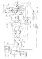
- FIG. 1illustrates a block diagram schematic of an exemplary propulsion system including a fault-mode processor in accordance with one aspect of the present invention
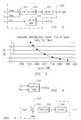
- FIG. 2shows a block diagram that illustrates further details regarding the fault-mode processor of FIG. 1;
- FIG. 3shows an exemplary plot of field weakening current, (Ids) as a function of rotor speed as may be provided during a fault condition
- FIG. 4illustrates an exemplary two-dimensional look-up table for generating the field weakening current, (Ids) during the fault condition
- FIG. 5shows a block diagram of a fault-mode processor in accordance with another aspect of the invention.
- FIG. 6shows a block diagram that illustrates further details regarding the fault-mode processor of FIG. 5.
- ⁇ qs e( ⁇ ds e ): q-axis (d-axis) component of stator voltage in synchronous reference frame.
- ⁇ ⁇ s s ( ⁇ ⁇ s )⁇ -axis ( ⁇ -axis) component of stator voltage in stationary reference frame.
- ⁇ ⁇ s s( ⁇ bs s , ⁇ cs s ): a-axis (b-axis, c-axis) component of stator voltage in stationary reference frame.
- V dcDC bus voltage
- V indexMagnitude of the applied machine voltage
- V limitLimit of the allowed voltage applied to the machine
- V marginA safety-margin value.
- V s maxMaximum output voltage inverter can provide in Space Vector Modulation.
- R sStator resistance
- ⁇ qs e( ⁇ ds e ): q-axis (d-axis) stator flux vector in synchronous reference frame.
- ⁇ qr e( ⁇ dr e ): q-axis (d-axis) rotor flux vector in synchronous reference frame.
- ⁇ e ( ⁇ r )Excitation (rotor) electrical angular frequency.
- T e *Torque reference of electric machine.
- Variable*Variable reference.
- V s *Voltage vector reference
- FIG. 1illustrates an exemplary propulsion system 100 configured to implement a rotor flux oriented (RFO) vector control technique using a PWM inverter controller 140 .
- RFO vector controlenables a permanent magnet machine 12 to be controlled in a similar way to a separately excited DC machine since the respective torque and flux current components can be independently controlled. As shown in FIG.
- the direct (d) axis current reference (I ds1 ) and the quadrature (q) axis current reference (I qs1 )may be adjusted as a function of commanded torque T e * and rotor speed ⁇ r using analytically and/or experimentally derived flux-adjusting values stored in a look-up table 102 that may comprise a two-dimensional look-up table responsive to two respective inputs to supply two outputs.
- Look-up table 102may be configured to provide optimum efficiency control for an ideal case by adjusting the value of the d axis current reference (I ds ) and the q axis current reference (I qs ) as a function of commanded torque T e * and rotor speed ⁇ r .
- the value of the torque reference signal T e *may be externally-derived by a system master controller or may correspond to the torque value commanded by an operator through a suitable machine propulsion throttle handle.
- the value of the rotor speed signal ⁇ rmay be derived from a rotor angle value ( ⁇ r ), upon execution of a mathematical differentiation operation by a differentiator 116 which receives a signal ⁇ r indicative of rotor shaft angle, such as may be generated by a shaft encoder 118 .
- a fault-mode processor 200upon sensing a fault mode of operation, a fault-mode processor 200 generates a switch control signal (sw_ctl) respectively applied to a switching device made up of a pair of switches 202 and 204 so that the values of the respective current components for the orthogonal d and q axis, e.g., I ds2 and I qs2 are computed or supplied by processor 200 in lieu of look-up table 102 .
- the fault conditionmay arise when an energy source, e.g., battery 206 , is disconnected. Some possible causes for the fault condition may include an open battery pack, an open fuse, an open connector, etc.
- the disconnection of battery 206could occur when a contactor 208 is commanded into an open condition, such as may occur during a battery protection fault mode condition.
- the switch control signalmay be derived based on various fault sensing conditions.
- the switch control signalcould be based on the contactor control signal, i.e., the values of the respective current components for the d and q axes would be provided by look-up table 102 when the contactor control signal indicates a closed contactor state.
- the values of the respective current components for the d and q axeswould be provided by processor 200 when the contactor control signal indicates an open contactor state.
- the switch control signalcould be derived by monitoring the voltage level of the DC bus, e.g., across a shunt impedance 210 , and determining whether the monitored voltage is within a desired voltage range.
- the values of the respective current components for the d and q axeswould be provided by look-up table 102 when the monitored DC bus voltage is within the desired voltage range.
- the values of the respective current components for the d and q axeswould be provided by processor 200 when the monitored DC bus voltage is outside the desired voltage range.
- the d axis current reference, (I ds ) and a feedback current signal Idis each respectively applied to a subtractor 122 to generate a difference output signal.
- the subtracting operation respectively executed by subtractor 122 and other such devices described belowmay be executed by a summer having one inverting input terminal and one non-inverting input terminal.
- any of the various arithmetic and logical operations performed in system 100may be conducted through respective software modules as may be executed in a suitable microprocessor and such operations need not be executed through hardware modules.
- the difference output signal from subtractor 122represents an error signal between the d axis current reference signal (Ids) and the feedback current signal Id.
- the torque-producing current component reference Iqsis processed by a subtractor 124 that receives a feedback current Iq.
- the difference output signal from subtractor 124represents an error signal between the torque current component reference signal Iqs and the feedback current signal Iq.
- a standard RFO vector controllermay comprise components such as respective voltage and current transformation units 126 and 128 , and two proportional plus integral (PI) current regulators 130 and 132 , each such component using techniques well-understood by those skilled in the art.
- PIproportional plus integral
- Current transformation unit 128converts the three-phase currents in the stationary frame into equivalent two-phase orthogonal currents in the rotor frame.
- the two orthogonal current signals I q and I d in the rotor frameare respectively applied to the two PI current regulators 130 and 132 as current feedback signals through subtractors 124 and 122 .
- the output signals from the PI current regulatorsare then provided to voltage transformation unit 126 and are converted into equivalent two-phase voltage references in the stationary frame.
- Each respective output signal of voltage transformation unit 126is then applied to a PWM inverter controller 140 that in one exemplary embodiment may comprise an over-modulation space vector PWM unit to generate three respective duty cycle values.
- controller functionalityis analogous to having six synchronous timers for respectively generating six-gate pulse signals to the respective gate drive circuits of an inverter 142 that energizes the phases of the permanent magnet machine 12 . It will be further appreciated that the inverter's legs will be appropriately switched on and off according to the voltage levels of the gate signals from the controller in order to control operation of the permanent magnet machine.
- the machinecould be operated for a short period of time as a motor but at the expense of lowering the capacitor voltage and increasing the required field-weakening current in order for the inverter to maintain current regulation capability and to protect the power electronics.
- This mode of operationcan be useful if the DC bus level is desired to be lowered to a safer level as may be required in a diagnostic or service mode.
- FIG. 2illustrates an exemplary embodiment of fault-mode processor 200 configured to generate the values of the current components for the d and q axis during the fault condition.
- a subtractor 250is coupled to receive a reference bus voltage value V bus * and the monitored bus voltage value V bus to generate a difference output signal.
- a current controller 252such as PI current controller, receives the difference output signal to supply an output signal supplied to a clamping or limiting device 254 so that any positive values of the torque-producing current component I qs2 are set to a negligible value, e.g., zero or other small value, and negative values of current component I qs2 would be allowed to pass through, if not overly large.
- a look-up table 256receives the rotor speed signal ⁇ r to generate the value of the flux-producing current I ds2 during the fault mode.
- FIG. 4shows an embodiment wherein look-up table 256 comprises a two-dimensional look-up table responsive to the rotor speed signal ⁇ r and the reference bus voltage value V bus * to generate I ds2 values.
- the two-dimensional look-up tableallows for accommodating distinct levels of bus voltages. These distinct level may be used due to a variety of considerations, such as diagnostics, safety, or efficiency reasons.
- the limiter ( 254 ) shown in FIG. 2would require a finite positive limit so that positive q-axis current could be commanded. The higher the positive limit on block ( 254 ) the quicker the bus voltage could be reduced.
- a two-dimensional look-up tableis shown in FIG. 4, it will be appreciated that a processor configured to provide a numerical solution to the pair of simultaneous equations 1 and 2 could be used in lieu of the look-up table.
- FIG. 5illustrates an exemplary embodiment wherein a fault-mode processor 300 is configured to generate a torque signal to be used during the fault mode.
- a switch 302is responsive to a switch control signal so that during normal operation the torque signal passed through switch 302 corresponds to the standard torque reference signal supplied by the system controller.
- switch 302is responsive to the switch control signal to pass the torque signal computed by processor 300 .
- the torque signal and the rotor speed signal ⁇ rare supplied to look-up table 102 as discussed in the context of FIG.
- FIG. 6illustrates an exemplary embodiment of fault-mode processor 300 configured to generate the values of the torque command signal during the fault condition.
- a subtractor 350is coupled to receive a reference bus voltage value V bus * and the monitored bus voltage value V bus to generate a difference output signal.
- a voltage controller 352such as PI controller, receives the difference output signal to supply an output signal to a clamping or limiting device 354 so that any positive values of the torque command signal are set to a small or zero value while negative values would be allow to pass through, if not overly large.
- the present inventioncan be embodied in the form of computer-implemented processes and apparatus for practicing those processes.
- the present inventioncan also be embodied in the form of computer program code containing computer-readable instructions embodied in tangible media, such as floppy diskettes, CD-ROMs, hard drives, or any other computer-readable storage medium, wherein, when the computer program code is loaded into and executed by a computer, the computer becomes an apparatus for practicing the invention.
- the present inventioncan also be embodied in the form of computer program code, for example, whether stored in a storage medium, loaded into and/or executed by a computer, or transmitted over some transmission medium, such as over electrical wiring or cabling, through fiber optics, or via electromagnetic radiation, wherein, when the computer program code is loaded into and executed by a computer, the computer becomes an apparatus for practicing the invention.
- the computer program code segmentsconfigure the computer to create specific logic circuits or processing modules.
Landscapes
- Engineering & Computer Science (AREA)
- Power Engineering (AREA)
- Life Sciences & Earth Sciences (AREA)
- Sustainable Development (AREA)
- Sustainable Energy (AREA)
- Transportation (AREA)
- Mechanical Engineering (AREA)
- Control Of Ac Motors In General (AREA)
Abstract
Description
- [0001] This invention was made with U.S. Government support through Definitized Subcontract C-HEV-5A under MRI/CHRYSLER LETTER SUBCONTRACT NO. ZAN-6-16334-01, which subcontract was in turn issued under MRI/CHRYSLER PRIME CONTRACT NO. DE-AC36-83CH10093” awarded by the Department of Energy, and, in accordance with the terms set forth in said contracts, the U.S. Government may have certain rights in the invention.
- The present invention is generally related to control of electromechanical machines, and, more particularly, the present invention is related to method and system for controlling a permanent magnet (PM) machine during fault conditions.[0002]
- In the control of inverter-driven PM machines used in propulsion systems, field weakening is often used to lower the inverter current and/or voltage rating for a given application. That is, without field weakening the inverter manufacturer would have to use components rated to handle higher levels of current and/or voltage for that given application. This would undesirably add incremental costs to the propulsion system. Field weakening is generally accomplished by configuring the machine windings to provide a greater torque per amp ratio, and thus achieve a lower base speed for a given torque load. During high speed operation, the phase current may be applied to the machine windings in advance of the phase electromotive force (EMF), and thus the EMF, while greater in peak magnitude than the energy source voltage, would have an apparent magnitude lower that the source voltage.[0003]
- Above the base speed of the machine, where the line-to-line EMF voltage due to the magnets has become greater or equal to the source voltage, a field-weakening current needs to be applied to the machine in order for torque to be realized. The flux created by this current is in opposition to the magnet's flux, and this reduces the effective EMF seen by the inverter. It should be stressed that this current should be carefully regulated to a target value set by the commanded torque and rotor speed. Failure to control the current to an appropriate value will likely result in the undesirable scenario that excessive voltage is applied to the inverter.[0004]
- The foregoing technique works well, except when the energy source, e.g., a battery, is intentionally or unintentionally disconnected and the machine is operating in the field-weakening mode. Under this condition, if corrective action is not taken, damage to the inverter could occur due to excessive voltage across the inverter and the DC bus. This excessive voltage is due to a charging mode overcharging the bus capacitance or a motoring mode depleting the bus capacitance to the point where the current can no longer be regulated. In either case, the EMF of the machine would be impressed on the inverter. If this voltage were to exceed the voltage ratings of the power semiconductor devices, or capacitors or other circuitry used by the system, costly damage to the system may occur.[0005]
- Thus, in view of the foregoing considerations, it would be desirable to provide a method and system for maintaining an appropriate level of field-weakening current and for controlling the DC bus voltage even in the absence of the energy source, and hence avoid exposing the system to potentially damaging high voltages.[0006]
- Generally speaking, the present invention fulfills the foregoing needs by providing in one exemplary embodiment thereof a method for controlling a permanent magnet machine driven by an inverter. The method allows for monitoring a signal indicative of a fault condition. The method further allows for generating during the fault condition a respective signal configured to maintain an appropriate field-weakening current that enables machine control and keeps circuitry in the motor-inverter system in a safe condition even though electrical power from an energy source is absent during said fault condition.[0007]
- In another aspect of the present invention, a control system for controlling a permanent magnet machine driven by an inverter is provided. The system includes a monitor coupled to receive a signal indicative of a fault condition. The system further includes a processor coupled to supply during the fault condition a respective signal configured to maintain an appropriate field-weakening current during said fault condition.[0008]
- The features and advantages of the present invention will become apparent from the following detailed description of the invention when read with the accompanying drawings in which:[0009]
- FIG. 1 illustrates a block diagram schematic of an exemplary propulsion system including a fault-mode processor in accordance with one aspect of the present invention;[0010]
- FIG. 2 shows a block diagram that illustrates further details regarding the fault-mode processor of FIG. 1;[0011]
- FIG. 3 shows an exemplary plot of field weakening current, (Ids) as a function of rotor speed as may be provided during a fault condition;[0012]
- FIG. 4 illustrates an exemplary two-dimensional look-up table for generating the field weakening current, (Ids) during the fault condition;[0013]
- FIG. 5 shows a block diagram of a fault-mode processor in accordance with another aspect of the invention; and[0014]
- FIG. 6 shows a block diagram that illustrates further details regarding the fault-mode processor of FIG. 5.[0015]
- Exemplary Nomenclature[0016]
- i[0017]qse(idse): q-axis (d-axis) component of stator current in synchronous reference frame.
- i[0018]αss(iβss): α-axis (β-axis) component of stator current in stationary reference frame.
- i[0019]αss(ibss, icss): a-axis (b-axis, c-axis) component of stator current in stationary reference frame.
- ν[0020]qse(νdse): q-axis (d-axis) component of stator voltage in synchronous reference frame.
- ν[0021]αss(νβs): α-axis (β-axis) component of stator voltage in stationary reference frame.
- ν[0022]αss(νbss, νcss): a-axis (b-axis, c-axis) component of stator voltage in stationary reference frame.
- V[0023]dc: DC bus voltage.
- V[0024]index: Magnitude of the applied machine voltage
- V[0025]limit: Limit of the allowed voltage applied to the machine
- V[0026]margin: A safety-margin value.
- V[0027]s max: Maximum output voltage inverter can provide in Space Vector Modulation.
- R[0028]s: Stator resistance.
- L[0029]ds: Stator D axis Inductance
- L[0030]qs: Stator Q axis Inductance
- λ[0031]qse(λdse): q-axis (d-axis) stator flux vector in synchronous reference frame.
- λ[0032]qre(λdre): q-axis (d-axis) rotor flux vector in synchronous reference frame.
- ω[0033]e(ωr): Excitation (rotor) electrical angular frequency.
- θ[0034]e(θr): Excitation (rotor) electrical angle
- T[0035]e*: Torque reference of electric machine.
- P: Number of poles.[0036]
- Variable*: Variable reference.[0037]
- V[0038]s*: Voltage vector reference.
- FIG. 1 illustrates an[0039]
exemplary propulsion system 100 configured to implement a rotor flux oriented (RFO) vector control technique using aPWM inverter controller 140. RFO vector control enables apermanent magnet machine 12 to be controlled in a similar way to a separately excited DC machine since the respective torque and flux current components can be independently controlled. As shown in FIG. 1, during a normal mode of operation, the direct (d) axis current reference (Ids1) and the quadrature (q) axis current reference (Iqs1) may be adjusted as a function of commanded torque Te* and rotor speed ωrusing analytically and/or experimentally derived flux-adjusting values stored in a look-up table102 that may comprise a two-dimensional look-up table responsive to two respective inputs to supply two outputs. Look-up table102 may be configured to provide optimum efficiency control for an ideal case by adjusting the value of the d axis current reference (Ids) and the q axis current reference (Iqs) as a function of commanded torque Te* and rotor speed ωr. The value of the torque reference signal Te* may be externally-derived by a system master controller or may correspond to the torque value commanded by an operator through a suitable machine propulsion throttle handle. The value of the rotor speed signal ωrmay be derived from a rotor angle value (θr), upon execution of a mathematical differentiation operation by adifferentiator 116 which receives a signal θr indicative of rotor shaft angle, such as may be generated by ashaft encoder 118. - As will be described in greater detail below, upon sensing a fault mode of operation, a fault-[0040]
mode processor 200 generates a switch control signal (sw_ctl) respectively applied to a switching device made up of a pair ofswitches processor 200 in lieu of look-up table102. The fault condition may arise when an energy source, e.g.,battery 206, is disconnected. Some possible causes for the fault condition may include an open battery pack, an open fuse, an open connector, etc. It will be appreciated that in some conditions, the disconnection ofbattery 206 could occur when acontactor 208 is commanded into an open condition, such as may occur during a battery protection fault mode condition. It will be appreciated that the switch control signal may be derived based on various fault sensing conditions. In one exemplary embodiment, the switch control signal could be based on the contactor control signal, i.e., the values of the respective current components for the d and q axes would be provided by look-up table102 when the contactor control signal indicates a closed contactor state. Conversely, the values of the respective current components for the d and q axes would be provided byprocessor 200 when the contactor control signal indicates an open contactor state. In another exemplary embodiment, the switch control signal could be derived by monitoring the voltage level of the DC bus, e.g., across ashunt impedance 210, and determining whether the monitored voltage is within a desired voltage range. For example, the values of the respective current components for the d and q axes would be provided by look-up table102 when the monitored DC bus voltage is within the desired voltage range. Conversely, the values of the respective current components for the d and q axes would be provided byprocessor 200 when the monitored DC bus voltage is outside the desired voltage range. - Regardless of the source, the d axis current reference, (I[0041]ds) and a feedback current signal Id is each respectively applied to a
subtractor 122 to generate a difference output signal. It will be understood that the subtracting operation respectively executed bysubtractor 122 and other such devices described below may be executed by a summer having one inverting input terminal and one non-inverting input terminal. It will be further understood that any of the various arithmetic and logical operations performed insystem 100 may be conducted through respective software modules as may be executed in a suitable microprocessor and such operations need not be executed through hardware modules. It will be appreciated that the difference output signal fromsubtractor 122 represents an error signal between the d axis current reference signal (Ids) and the feedback current signal Id. Similarly, the torque-producing current component reference Iqs is processed by asubtractor 124 that receives a feedback current Iq. In this case, the difference output signal fromsubtractor 124 represents an error signal between the torque current component reference signal Iqs and the feedback current signal Iq. - By way of example and not of limitation, a standard RFO vector controller may comprise components such as respective voltage and[0042]
current transformation units current regulators Current transformation unit 128 converts the three-phase currents in the stationary frame into equivalent two-phase orthogonal currents in the rotor frame. After the transformation is performed, the two orthogonal current signals Iqand Idin the rotor frame are respectively applied to the two PIcurrent regulators subtractors voltage transformation unit 126 and are converted into equivalent two-phase voltage references in the stationary frame. Each respective output signal ofvoltage transformation unit 126 is then applied to aPWM inverter controller 140 that in one exemplary embodiment may comprise an over-modulation space vector PWM unit to generate three respective duty cycle values. It will be appreciated that the controller functionality is analogous to having six synchronous timers for respectively generating six-gate pulse signals to the respective gate drive circuits of aninverter 142 that energizes the phases of thepermanent magnet machine 12. It will be further appreciated that the inverter's legs will be appropriately switched on and off according to the voltage levels of the gate signals from the controller in order to control operation of the permanent magnet machine. - As will be readily appreciated by those of ordinary skill in the art, the mathematical equations that describe the behavior of a Permanent Magnet machine in a RFO (Rotor Flux Oriented) reference frame are given by:[0043]
- νqse=rs·iqse+pλqse+ωe·λdse
- νdse=rs·idse+pλdse−ωe·λqse (1)
- where:[0044]
- λqseLqsiqse
- λdse=λmagnet+Ldsidse
- In order to ensure stable operation in the field-weakened range, the following constraint should be considered:[0045]
- {square root}{square root over ((νqse)2+(νdse)2≦Vs max−Vmargin)} (2)
- where greater efficiency is achieved by operating with the voltage as close as possible to the limit indicated by[0046]
equation 2. - In the field-weakened condition the predominant voltage drop is caused by the EMF terms. Once a fault condition is sensed, it has been demonstrated by the inventors of the present invention that if one were to appropriately adjust the values of the current components for the d and q axis, one can conceptually operate the machine as a generator, i.e., generating only sufficient power to supply the machine with field-weakening current. In this mode of operation, the electric machine would provide enough power to overcome the resistive power loss of the machine and the switching losses of the inverter. Since only the power loss of the machine and inverter is being supplied, the DC capacitor's voltage level would not change. The capacitor voltage should be maintained for the machine controller to regulate the field-weakening current to protect the inverter. In addition, if the voltage level is maintained generally constant then the field-weakening current can be chosen as a function of speed.[0047]
- It will be appreciated that the machine could be operated for a short period of time as a motor but at the expense of lowering the capacitor voltage and increasing the required field-weakening current in order for the inverter to maintain current regulation capability and to protect the power electronics. This mode of operation can be useful if the DC bus level is desired to be lowered to a safer level as may be required in a diagnostic or service mode.[0048]
- FIG. 2 illustrates an exemplary embodiment of fault-[0049]
mode processor 200 configured to generate the values of the current components for the d and q axis during the fault condition. As shown in FIG. 2, asubtractor 250 is coupled to receive a reference bus voltage value Vbus* and the monitored bus voltage value Vbusto generate a difference output signal. Acurrent controller 252, such as PI current controller, receives the difference output signal to supply an output signal supplied to a clamping or limitingdevice 254 so that any positive values of the torque-producing current component Iqs2are set to a negligible value, e.g., zero or other small value, and negative values of current component Iqs2would be allowed to pass through, if not overly large. A look-up table256 receives the rotor speed signal ωrto generate the value of the flux-producing current Ids2during the fault mode. An exemplary plot of Ids2values as a function of rotor speed, as may be stored in look-up table256, is illustrated in FIG. 3. - FIG. 4 shows an embodiment wherein look-up table[0050]256 comprises a two-dimensional look-up table responsive to the rotor speed signal ωrand the reference bus voltage value Vbus* to generate Ids2values. It will be appreciated that the two-dimensional look-up table allows for accommodating distinct levels of bus voltages. These distinct level may be used due to a variety of considerations, such as diagnostics, safety, or efficiency reasons. In the context of this variation, the limiter (254) shown in FIG. 2 would require a finite positive limit so that positive q-axis current could be commanded. The higher the positive limit on block (254) the quicker the bus voltage could be reduced. Although a two-dimensional look-up table is shown in FIG. 4, it will be appreciated that a processor configured to provide a numerical solution to the pair of
simultaneous equations 1 and 2 could be used in lieu of the look-up table. - FIG. 5 illustrates an exemplary embodiment wherein a fault-[0051]
mode processor 300 is configured to generate a torque signal to be used during the fault mode. In this embodiment, aswitch 302 is responsive to a switch control signal so that during normal operation the torque signal passed throughswitch 302 corresponds to the standard torque reference signal supplied by the system controller. Conversely, during a fault mode of operation, switch302 is responsive to the switch control signal to pass the torque signal computed byprocessor 300. In either mode, the torque signal and the rotor speed signal ωrare supplied to look-up table102 as discussed in the context of FIG. 1 to generate the value of the d axis current reference (Ids) and the q axis current reference (Iqs) as a function of the commanded torque signal and rotor speed ωr. The respective Idsand Iqscurrent components would be then be processed as shown in FIG. 1. - FIG. 6 illustrates an exemplary embodiment of fault-[0052]
mode processor 300 configured to generate the values of the torque command signal during the fault condition. As shown in FIG. 6, asubtractor 350 is coupled to receive a reference bus voltage value Vbus* and the monitored bus voltage value Vbusto generate a difference output signal. Avoltage controller 352, such as PI controller, receives the difference output signal to supply an output signal to a clamping or limitingdevice 354 so that any positive values of the torque command signal are set to a small or zero value while negative values would be allow to pass through, if not overly large. - The present invention can be embodied in the form of computer-implemented processes and apparatus for practicing those processes. The present invention can also be embodied in the form of computer program code containing computer-readable instructions embodied in tangible media, such as floppy diskettes, CD-ROMs, hard drives, or any other computer-readable storage medium, wherein, when the computer program code is loaded into and executed by a computer, the computer becomes an apparatus for practicing the invention. The present invention can also be embodied in the form of computer program code, for example, whether stored in a storage medium, loaded into and/or executed by a computer, or transmitted over some transmission medium, such as over electrical wiring or cabling, through fiber optics, or via electromagnetic radiation, wherein, when the computer program code is loaded into and executed by a computer, the computer becomes an apparatus for practicing the invention. When implemented on a general-purpose computer, the computer program code segments configure the computer to create specific logic circuits or processing modules.[0053]
- While the preferred embodiments of the present invention have been shown and described herein, it will be obvious that such embodiments are provided by way of example only. Numerous variations, changes and substitutions will occur to those of skill in the art without departing from the invention herein. Accordingly, it is intended that the invention be limited only by the spirit and scope of the appended claims.[0054]
Claims (21)
1. A method for controlling an inverter-driven permanent magnet machine, the method comprising:
monitoring a signal indicative of a fault condition; and
generating during the fault condition a respective signal configured to maintain a field-weakening current that allows control of the machine and inverter circuitry protection even though electrical power from an energy source is absent during said fault condition.
2. The control method ofclaim 1 wherein said generated signal comprises two mutually orthogonal current components, and further wherein one of said current components comprises a torque-producing current component, the level of said torque-producing component during said fault condition being limited to values not exceeding a positive limit.
3. The control method ofclaim 2 wherein positive values of said torque-producing current component are used to set a direct current bus coupled to the inverter to a commanded level.
4. The control method ofclaim 2 wherein another of said current components comprises a flux-producing current component and wherein the value of said flux-producing component during said fault condition is based on rotor speed of the machine.
5. The control method ofclaim 4 wherein the value of said flux-producing component during said fault condition is further based on the voltage level of a direct current bus coupled to the inverter.
6. The control method ofclaim 2 further comprising generating a switching control signal in response to the monitored signal to switch between respective distinct sources of the current components, one of said sources used during a normal condition and another of said sources used during the fault condition.
7. The control method ofclaim 1 wherein said generated signal comprises a torque command signal and wherein the value of said torque command signal during said fault condition being limited to values not exceeding a positive limit.
8. The control method ofclaim 6 further comprising generating a switching control signal in response to the monitored signal to switch between distinct sources of the torque command signal, one of said sources used during a normal condition and another of said sources used during the fault condition.
9. A control system for controlling an inverter-driven permanent magnet machine, the system comprising:
a monitor coupled to receive a signal indicative of a fault condition; and
a processor coupled to supply during the fault condition a respective signal configured to maintain a field weakening current during said fault condition.
10. The control system ofclaim 9 wherein said field-weakening current allows control of the machine and inverter circuitry protection even though electrical power from an energy source is absent during said fault condition.
11. The control system ofclaim 9 wherein the signal from said processor comprises two mutually orthogonal current components, and further wherein one of said current components comprises a torque-producing current component, the value of said torque-producing component during said fault condition being limited to values not exceeding a positive limit.
12. The control method ofclaim 11 wherein positive values of said torque-producing current component are used to set a direct current bus coupled to the inverter to a commanded value.
13. The control system ofclaim 11 wherein another of said current components comprises a flux-producing current component and wherein the value of said flux-producing component during said fault condition is based on rotor speed of the machine.
14. The control system ofclaim 11 wherein the value of said flux-producing component during said fault condition is further based on the voltage level of a direct current bus coupled to the inverter.
15. The control system ofclaim 11 further comprising a switching unit responsive to a switching control signal to switch between respective distinct sources of the current components, one of said sources used during a normal condition and another of said sources used during the fault condition.
16. The control system ofclaim 15 wherein said processor comprises the source used during the fault condition and includes a look-up table configured to store values of said flux-producing current component as a function of rotor speed.
17. The control system ofclaim 16 wherein said stored values are further based on a sensed voltage level of a direct current bus coupled to the inverter.
18. The control system ofclaim 17 wherein said processor further includes a controller responsive to a difference output signal indicative of the difference between a reference bus voltage value and the sensed bus voltage value, and a limiter coupled to said controller to supply the torque-producing current component.
19. The control system ofclaim 9 wherein the signal from said processor comprises a torque command signal and wherein the level of said torque command signal during said fault condition is limited to values not exceeding a positive limit.
20. The control system ofclaim 19 further comprising a switching module responsive to a switching control signal to switch between distinct sources of the torque command signal, one of said sources used during a normal condition and another of said sources used during the fault condition.
21. The control system of claim20 wherein said processor comprises the source used during the fault condition, and said processor includes a controller responsive to a difference output signal indicative of the difference between a reference bus voltage value and a sensed bus voltage value, and a limiter coupled to said controller to supply the torque command signal.
Priority Applications (2)
| Application Number | Priority Date | Filing Date | Title |
|---|---|---|---|
| US09/827,052US6741060B2 (en) | 2001-04-05 | 2001-04-05 | Method and system for controlling a permanent magnet machine during fault conditions |
| EP20020076081EP1248342A1 (en) | 2001-04-05 | 2002-03-20 | Method and system for controlling a permanent magnet machine during fault conditions |
Applications Claiming Priority (1)
| Application Number | Priority Date | Filing Date | Title |
|---|---|---|---|
| US09/827,052US6741060B2 (en) | 2001-04-05 | 2001-04-05 | Method and system for controlling a permanent magnet machine during fault conditions |
Publications (2)
| Publication Number | Publication Date |
|---|---|
| US20020145837A1true US20020145837A1 (en) | 2002-10-10 |
| US6741060B2 US6741060B2 (en) | 2004-05-25 |
Family
ID=25248203
Family Applications (1)
| Application Number | Title | Priority Date | Filing Date |
|---|---|---|---|
| US09/827,052Expired - LifetimeUS6741060B2 (en) | 2001-04-05 | 2001-04-05 | Method and system for controlling a permanent magnet machine during fault conditions |
Country Status (2)
| Country | Link |
|---|---|
| US (1) | US6741060B2 (en) |
| EP (1) | EP1248342A1 (en) |
Cited By (37)
| Publication number | Priority date | Publication date | Assignee | Title |
|---|---|---|---|---|
| US6850033B1 (en) | 2003-08-26 | 2005-02-01 | Delphi Technologies, Inc. | System and method for clamp current regulation of induction machines |
| US20050046370A1 (en)* | 2003-08-26 | 2005-03-03 | Gabriel Gallegos-Lopez | System and method for clamp current regulation in field-weakening operation of permanent magnet (PM) machines |
| US7279862B1 (en)* | 2006-08-04 | 2007-10-09 | Gm Global Technology Operations, Inc. | Fault handling of inverter driven PM motor drives |
| US7282886B1 (en)* | 2006-08-04 | 2007-10-16 | Gm Global Technology Operations, Inc. | Method and system for controlling permanent magnet motor drive systems |
| US20070248338A1 (en)* | 2004-07-07 | 2007-10-25 | Hitachi Ltd., | Motor Controlling Device for Mounting on Vehicle |
| US20080185983A1 (en)* | 2007-02-05 | 2008-08-07 | Jtekt Corporation | Motor controller and electric power steering apparatus |
| US20080203958A1 (en)* | 2007-02-26 | 2008-08-28 | Jtekt Corporation | Motor controller and electric power steering apparatus |
| US20080203963A1 (en)* | 2007-02-26 | 2008-08-28 | Jtekt Corporation | Motor controller and electric power steering apparatus |
| US20080290829A1 (en)* | 2007-02-26 | 2008-11-27 | Jtekt Corporation | Motor controller and electric power steering apparatus |
| US20080297958A1 (en)* | 2007-06-01 | 2008-12-04 | Jtekt Corporation | Motor controller and electric power steering apparatus |
| US20080309270A1 (en)* | 2007-06-14 | 2008-12-18 | Jtekt Corporation | Motor controller and electric power steering apparatus |
| US20090079371A1 (en)* | 2007-09-26 | 2009-03-26 | Jtekt Corporation | Motor controller and electric power steering apparatus |
| US20100320953A1 (en)* | 2009-06-18 | 2010-12-23 | Gm Global Technology Operations, Inc. | Methods and systems for diagnosing stator windings in an electric motor |
| US20110031911A1 (en)* | 2009-08-10 | 2011-02-10 | Emerson Climate Technologies, Inc. | Power factor correction with variable bus voltage |
| US20110031920A1 (en)* | 2009-08-10 | 2011-02-10 | Emerson Climate Technologies, Inc. | Controller and method for estimating, managing, and diagnosing motor parameters |
| US20110089882A1 (en)* | 2009-10-20 | 2011-04-21 | Gm Global Technology Operations, Inc. | Methods and systems for performing fault diagnostics for rotors of electric motors |
| US20110096470A1 (en)* | 2006-06-01 | 2011-04-28 | Joseph Scott Dixon | Systems, devices, and methods for distributing electrical energy |
| US20110140643A1 (en)* | 2010-08-26 | 2011-06-16 | Ford Global Technologies, Llc | Electric motor torque estimation |
| US20110234126A1 (en)* | 2010-03-25 | 2011-09-29 | Gm Global Technology Operations, Inc. | Method and apparatus to monitor an electric motor control circuit |
| US20120139459A1 (en)* | 2010-12-06 | 2012-06-07 | Hyundai Motor Company | System for controlling motor of hybrid vehicle |
| US8319458B2 (en) | 2010-06-17 | 2012-11-27 | GM Global Technology Operations LLC | Vehicular electrical system and method for controlling an inverter during motor deceleration |
| US8446113B2 (en) | 2010-06-17 | 2013-05-21 | GM Global Technology Operations LLC | Vehicular electrical system and method for controlling an inverter during motor deceleration |
| CN103155401A (en)* | 2011-09-12 | 2013-06-12 | 日本精工株式会社 | Motor control device and electric power steering device |
| CN103199785A (en)* | 2012-01-05 | 2013-07-10 | 通用汽车环球科技运作有限责任公司 | Methods, systems and apparatus for generating current commands used to control operation of an electric machine |
| US8497698B2 (en) | 2010-08-11 | 2013-07-30 | GM Global Technology Operations LLC | Methods and systems for diagnosing faults for rotors of electric motors |
| US20130342142A1 (en)* | 2012-04-26 | 2013-12-26 | Emerson Climate Technologies, Inc. | System And Method for Permanent Magnet Motor Control |
| US8698433B2 (en) | 2009-08-10 | 2014-04-15 | Emerson Climate Technologies, Inc. | Controller and method for minimizing phase advance current |
| US20140203754A1 (en)* | 2013-01-24 | 2014-07-24 | Rolls-Royce Plc | Method of controlling an ac machine and controller for controlling an ac machine |
| US9018881B2 (en) | 2013-01-10 | 2015-04-28 | GM Global Technology Operations LLC | Stator winding diagnostic systems and methods |
| US9154061B2 (en) | 2009-08-10 | 2015-10-06 | Emerson Climate Technologies, Inc. | Controller and method for transitioning between control angles |
| JP2015192473A (en)* | 2014-03-27 | 2015-11-02 | 日本電産サンキョー株式会社 | servo motor control system and servo motor control method |
| US9240749B2 (en) | 2012-08-10 | 2016-01-19 | Emerson Climate Technologies, Inc. | Motor drive control using pulse-width modulation pulse skipping |
| US20160204727A1 (en)* | 2014-10-21 | 2016-07-14 | Denso Corporation | Controller and control method for rotary electric machine |
| EP2048772A4 (en)* | 2006-07-24 | 2017-01-11 | Kabushiki Kaisha Toshiba | Variable magnetic flux motor drive system |
| US10454395B2 (en)* | 2017-11-06 | 2019-10-22 | Steering Solutions Ip Holding Corporation | Power management in permanent magnet synchronous motor drives |
| CN112825467A (en)* | 2019-11-15 | 2021-05-21 | 操纵技术Ip控股公司 | Battery current limit for permanent magnet synchronous motor drive |
| US11789081B2 (en)* | 2014-10-07 | 2023-10-17 | Texas Instruments Incorporated | Detecting faults in field oriented controlled permanent magnet synchronous machines |
Families Citing this family (20)
| Publication number | Priority date | Publication date | Assignee | Title |
|---|---|---|---|---|
| US6876169B2 (en)* | 2003-01-14 | 2005-04-05 | Delphi Technologies, Inc. | Method and controller for field weakening operation of AC machines |
| US6864662B2 (en)* | 2003-04-30 | 2005-03-08 | Visteon Global Technologies, Inc. | Electric power assist steering system and method of operation |
| US7015667B2 (en)* | 2004-03-24 | 2006-03-21 | General Motors Corporation | Current regulation for a field weakening motor control system and method |
| US20060043923A1 (en)* | 2004-08-31 | 2006-03-02 | Baker Donal E | Performance enhancement for motor field oriented control system |
| US7023168B1 (en)* | 2004-09-13 | 2006-04-04 | General Motors Corporation | Field weakening motor control system and method |
| US7375934B2 (en)* | 2004-09-20 | 2008-05-20 | Honeywell International Inc. | Power converter controlling apparatus and method applying a fault protection scheme in a motor drive system |
| US7088077B2 (en)* | 2004-11-09 | 2006-08-08 | General Motors Corporation | Position-sensorless control of interior permanent magnet machines |
| US7211984B2 (en)* | 2004-11-09 | 2007-05-01 | General Motors Corporation | Start-up and restart of interior permanent magnet machines |
| WO2006124010A1 (en)* | 2005-05-16 | 2006-11-23 | General Motors Corporation | Current regulation for a field weakening motor control system and method |
| EP2306634A3 (en)* | 2005-06-30 | 2015-04-29 | Continental Automotive Systems US, Inc. | Control system for electric drives |
| JP4655871B2 (en)* | 2005-10-19 | 2011-03-23 | 株式会社日立製作所 | Field weakening vector control device and module for permanent magnet synchronous motor |
| DE102006042038B3 (en)* | 2006-09-07 | 2008-02-07 | Siemens Ag | Field-oriented driven inverter-fed three-phase alternating current motor torque limiting method, involves generating impulse resetting signal when threshold value exceeds or torque-forming current components are unequal |
| JP4971039B2 (en) | 2007-06-07 | 2012-07-11 | 本田技研工業株式会社 | Motor control device |
| US20100066289A1 (en) | 2008-09-17 | 2010-03-18 | Ford Global Technologies, Llc | System and method for controlling an electric motor |
| US8963459B2 (en)* | 2011-09-07 | 2015-02-24 | Samsung Techwin Co., Ltd. | Method and apparatus for driving alternating-current motor |
| US8981686B2 (en) | 2013-01-24 | 2015-03-17 | Regal Beloit America, Inc. | Methods and systems for controlling an electric motor |
| DE102013213044A1 (en)* | 2013-07-04 | 2015-01-08 | Voith Patent Gmbh | Permanent magnet electric machine |
| CN105634355B (en)* | 2014-11-05 | 2020-03-06 | 博世力士乐(西安)电子传动与控制有限公司 | Frequency converter and control device and control method for frequency converter |
| US10298154B2 (en)* | 2016-06-10 | 2019-05-21 | Abb Schweiz Ag | Restart strategy for synchronous reluctance machines |
| CN110190794A (en)* | 2019-04-12 | 2019-08-30 | 北京航天发射技术研究所 | Calculation method and device for current given value of built-in permanent magnet synchronous motor |
Family Cites Families (7)
| Publication number | Priority date | Publication date | Assignee | Title |
|---|---|---|---|---|
| US5504404A (en) | 1993-09-17 | 1996-04-02 | Matsushita Electric Industrial Co., Ltd. | Method and apparatus for controlling motor |
| JP3542198B2 (en) | 1995-04-28 | 2004-07-14 | 本田技研工業株式会社 | Control device for electric vehicle |
| JP3542197B2 (en) | 1995-04-28 | 2004-07-14 | 本田技研工業株式会社 | Control device for electric vehicle |
| US6008602A (en) | 1996-06-07 | 1999-12-28 | Papst-Motoren Gmbh & Co. Kg | Arrangement with an electronically commutated motor |
| ES2158782B1 (en)* | 1998-05-12 | 2002-03-01 | Mannesmann Sachs Ag | CONTROL SYSTEM AND PROCEDURE FOR A PERMANENTLY EXCITED ELECTRIC MOTOR WITH AT LEAST ONE PHASE. |
| JP3566163B2 (en)* | 2000-01-07 | 2004-09-15 | 株式会社東芝 | Motor control device |
| US6407531B1 (en)* | 2001-01-09 | 2002-06-18 | Delphi Technologies, Inc. | Method and system for controlling a synchronous machine over full operating range |
- 2001
- 2001-04-05USUS09/827,052patent/US6741060B2/ennot_activeExpired - Lifetime
- 2002
- 2002-03-20EPEP20020076081patent/EP1248342A1/ennot_activeWithdrawn
Cited By (70)
| Publication number | Priority date | Publication date | Assignee | Title |
|---|---|---|---|---|
| US20050046370A1 (en)* | 2003-08-26 | 2005-03-03 | Gabriel Gallegos-Lopez | System and method for clamp current regulation in field-weakening operation of permanent magnet (PM) machines |
| US7242163B2 (en) | 2003-08-26 | 2007-07-10 | Delphi Technologies, Inc. | System and method for clamp current regulation in field-weakening operation of permanent magnet (PM) machines |
| US6850033B1 (en) | 2003-08-26 | 2005-02-01 | Delphi Technologies, Inc. | System and method for clamp current regulation of induction machines |
| US7560886B2 (en) | 2004-07-07 | 2009-07-14 | Hitachi, Ltd. | Motor controlling device for mounting on vehicle |
| EP1768252A4 (en)* | 2004-07-07 | 2009-01-07 | Hitachi Ltd | DEVICE FOR CONTROLLING ENGINE TO BE MOUNTED ON A VEHICLE |
| US20070248338A1 (en)* | 2004-07-07 | 2007-10-25 | Hitachi Ltd., | Motor Controlling Device for Mounting on Vehicle |
| US20110096470A1 (en)* | 2006-06-01 | 2011-04-28 | Joseph Scott Dixon | Systems, devices, and methods for distributing electrical energy |
| EP2048772A4 (en)* | 2006-07-24 | 2017-01-11 | Kabushiki Kaisha Toshiba | Variable magnetic flux motor drive system |
| US7279862B1 (en)* | 2006-08-04 | 2007-10-09 | Gm Global Technology Operations, Inc. | Fault handling of inverter driven PM motor drives |
| USRE42200E1 (en)* | 2006-08-04 | 2011-03-08 | GM Global Technology Operations LLC | Fault handling of inverter driven PM motor drives |
| US7282886B1 (en)* | 2006-08-04 | 2007-10-16 | Gm Global Technology Operations, Inc. | Method and system for controlling permanent magnet motor drive systems |
| US20080185983A1 (en)* | 2007-02-05 | 2008-08-07 | Jtekt Corporation | Motor controller and electric power steering apparatus |
| US7813626B2 (en)* | 2007-02-05 | 2010-10-12 | Jtekt Corporation | Motor controller and electric power steering apparatus |
| US7843154B2 (en) | 2007-02-26 | 2010-11-30 | Jtekt Corporation | Motor controller and electric power steering apparatus |
| US20080290829A1 (en)* | 2007-02-26 | 2008-11-27 | Jtekt Corporation | Motor controller and electric power steering apparatus |
| US20080203958A1 (en)* | 2007-02-26 | 2008-08-28 | Jtekt Corporation | Motor controller and electric power steering apparatus |
| US7813089B2 (en) | 2007-02-26 | 2010-10-12 | Jtekt Corporation | Motor controller and electric power steering apparatus |
| US20080203963A1 (en)* | 2007-02-26 | 2008-08-28 | Jtekt Corporation | Motor controller and electric power steering apparatus |
| US7859206B2 (en) | 2007-02-26 | 2010-12-28 | Jtekt Corporation | Motor controller and electric power steering apparatus |
| US7782000B2 (en) | 2007-06-01 | 2010-08-24 | Jtekt Corporation | Motor controller and electric power steering apparatus |
| US20080297958A1 (en)* | 2007-06-01 | 2008-12-04 | Jtekt Corporation | Motor controller and electric power steering apparatus |
| US7880417B2 (en) | 2007-06-14 | 2011-02-01 | Jtekt Corporation | Motor controller and electric power steering apparatus |
| US20080309270A1 (en)* | 2007-06-14 | 2008-12-18 | Jtekt Corporation | Motor controller and electric power steering apparatus |
| US8008880B2 (en) | 2007-09-26 | 2011-08-30 | Jtekt Corporation | Motor controller and electric power steering apparatus |
| US20090079371A1 (en)* | 2007-09-26 | 2009-03-26 | Jtekt Corporation | Motor controller and electric power steering apparatus |
| US8354817B2 (en) | 2009-06-18 | 2013-01-15 | GM Global Technology Operations LLC | Methods and systems for diagnosing stator windings in an electric motor |
| US20100320953A1 (en)* | 2009-06-18 | 2010-12-23 | Gm Global Technology Operations, Inc. | Methods and systems for diagnosing stator windings in an electric motor |
| US9705433B2 (en) | 2009-08-10 | 2017-07-11 | Emerson Climate Technologies, Inc. | Controller and method for transitioning between control angles |
| US9912263B2 (en) | 2009-08-10 | 2018-03-06 | Emerson Climate Technologies, Inc. | Controller and method for transitioning between control angles |
| US9564846B2 (en) | 2009-08-10 | 2017-02-07 | Emerson Climate Technologies, Inc. | Power factor correction with variable bus voltage |
| US20110031920A1 (en)* | 2009-08-10 | 2011-02-10 | Emerson Climate Technologies, Inc. | Controller and method for estimating, managing, and diagnosing motor parameters |
| US9154061B2 (en) | 2009-08-10 | 2015-10-06 | Emerson Climate Technologies, Inc. | Controller and method for transitioning between control angles |
| US9088232B2 (en) | 2009-08-10 | 2015-07-21 | Emerson Climate Technologies, Inc. | Power factor correction with variable bus voltage |
| US20110031911A1 (en)* | 2009-08-10 | 2011-02-10 | Emerson Climate Technologies, Inc. | Power factor correction with variable bus voltage |
| US8493014B2 (en)* | 2009-08-10 | 2013-07-23 | Emerson Climate Technologies, Inc. | Controller and method for estimating, managing, and diagnosing motor parameters |
| US8698433B2 (en) | 2009-08-10 | 2014-04-15 | Emerson Climate Technologies, Inc. | Controller and method for minimizing phase advance current |
| US8508166B2 (en) | 2009-08-10 | 2013-08-13 | Emerson Climate Technologies, Inc. | Power factor correction with variable bus voltage |
| US20110089882A1 (en)* | 2009-10-20 | 2011-04-21 | Gm Global Technology Operations, Inc. | Methods and systems for performing fault diagnostics for rotors of electric motors |
| US8253365B2 (en)* | 2009-10-20 | 2012-08-28 | GM Global Technology Operations LLC | Methods and systems for performing fault diagnostics for rotors of electric motors |
| US8334670B2 (en)* | 2010-03-25 | 2012-12-18 | GM Global Technology Operations LLC | Method and apparatus to monitor an electric motor control circuit |
| US20110234126A1 (en)* | 2010-03-25 | 2011-09-29 | Gm Global Technology Operations, Inc. | Method and apparatus to monitor an electric motor control circuit |
| US8446113B2 (en) | 2010-06-17 | 2013-05-21 | GM Global Technology Operations LLC | Vehicular electrical system and method for controlling an inverter during motor deceleration |
| US8319458B2 (en) | 2010-06-17 | 2012-11-27 | GM Global Technology Operations LLC | Vehicular electrical system and method for controlling an inverter during motor deceleration |
| US8497698B2 (en) | 2010-08-11 | 2013-07-30 | GM Global Technology Operations LLC | Methods and systems for diagnosing faults for rotors of electric motors |
| CN103259482A (en)* | 2010-08-26 | 2013-08-21 | 福特全球技术公司 | Electric motor torque estimation |
| US8080956B2 (en)* | 2010-08-26 | 2011-12-20 | Ford Global Technologies, Llc | Electric motor torque estimation |
| CN102386817A (en)* | 2010-08-26 | 2012-03-21 | 福特全球技术公司 | Electric motor torque estimation |
| US20110140643A1 (en)* | 2010-08-26 | 2011-06-16 | Ford Global Technologies, Llc | Electric motor torque estimation |
| US20120139459A1 (en)* | 2010-12-06 | 2012-06-07 | Hyundai Motor Company | System for controlling motor of hybrid vehicle |
| US8664900B2 (en)* | 2010-12-06 | 2014-03-04 | Hyundai Motor Company | System for controlling motor of hybrid vehicle |
| CN103155401A (en)* | 2011-09-12 | 2013-06-12 | 日本精工株式会社 | Motor control device and electric power steering device |
| US20130158808A1 (en)* | 2011-09-12 | 2013-06-20 | Nsk Ltd. | Motor control apparatus and electric power steering apparatus |
| US8725357B2 (en)* | 2011-09-12 | 2014-05-13 | Nsk Ltd. | Motor control apparatus and electric power steering apparatus |
| CN103199785A (en)* | 2012-01-05 | 2013-07-10 | 通用汽车环球科技运作有限责任公司 | Methods, systems and apparatus for generating current commands used to control operation of an electric machine |
| US8729847B2 (en) | 2012-01-05 | 2014-05-20 | GM Global Technology Operations LLC | Methods, systems and apparatus for generating current commands used to control operation of an electric machine |
| US20130342142A1 (en)* | 2012-04-26 | 2013-12-26 | Emerson Climate Technologies, Inc. | System And Method for Permanent Magnet Motor Control |
| US9991834B2 (en) | 2012-04-26 | 2018-06-05 | Emerson Climate Technologies, Inc. | System and method for permanent magnet motor control |
| US10075116B2 (en) | 2012-04-26 | 2018-09-11 | Emerson Climate Technologies, Inc. | System and method for permanent magnet motor control |
| US9634593B2 (en)* | 2012-04-26 | 2017-04-25 | Emerson Climate Technologies, Inc. | System and method for permanent magnet motor control |
| US9240749B2 (en) | 2012-08-10 | 2016-01-19 | Emerson Climate Technologies, Inc. | Motor drive control using pulse-width modulation pulse skipping |
| US9853588B2 (en) | 2012-08-10 | 2017-12-26 | Emerson Climate Technologies, Inc. | Motor drive control using pulse-width modulation pulse skipping |
| US9018881B2 (en) | 2013-01-10 | 2015-04-28 | GM Global Technology Operations LLC | Stator winding diagnostic systems and methods |
| US20140203754A1 (en)* | 2013-01-24 | 2014-07-24 | Rolls-Royce Plc | Method of controlling an ac machine and controller for controlling an ac machine |
| JP2015192473A (en)* | 2014-03-27 | 2015-11-02 | 日本電産サンキョー株式会社 | servo motor control system and servo motor control method |
| US11789081B2 (en)* | 2014-10-07 | 2023-10-17 | Texas Instruments Incorporated | Detecting faults in field oriented controlled permanent magnet synchronous machines |
| US9847744B2 (en)* | 2014-10-21 | 2017-12-19 | Denso Corporation | Controller and control method for rotary electric machine |
| US20160204727A1 (en)* | 2014-10-21 | 2016-07-14 | Denso Corporation | Controller and control method for rotary electric machine |
| US10454395B2 (en)* | 2017-11-06 | 2019-10-22 | Steering Solutions Ip Holding Corporation | Power management in permanent magnet synchronous motor drives |
| CN112825467A (en)* | 2019-11-15 | 2021-05-21 | 操纵技术Ip控股公司 | Battery current limit for permanent magnet synchronous motor drive |
| US11424706B2 (en)* | 2019-11-15 | 2022-08-23 | Steering Solutions Ip Holding Corporation | Battery current limiting of permanent magnet synchronous motor drives using operation condition monitoring |
Also Published As
| Publication number | Publication date |
|---|---|
| EP1248342A1 (en) | 2002-10-09 |
| US6741060B2 (en) | 2004-05-25 |
Similar Documents
| Publication | Publication Date | Title |
|---|---|---|
| US6741060B2 (en) | Method and system for controlling a permanent magnet machine during fault conditions | |
| US6407531B1 (en) | Method and system for controlling a synchronous machine over full operating range | |
| Ho et al. | Decoupling control of induction motor drives | |
| US9048773B2 (en) | Method and device for regulating separately excited synchronous machines | |
| US7242163B2 (en) | System and method for clamp current regulation in field-weakening operation of permanent magnet (PM) machines | |
| US7855526B2 (en) | Power conversion control device, power conversion control method, and power conversion control program | |
| US6876169B2 (en) | Method and controller for field weakening operation of AC machines | |
| EP2464002B1 (en) | Estimation of actual torque in an electrical motor drive | |
| EP3950403A1 (en) | Drive device for permanent-magnet synchronous machine, torque compensation method for permanent-magnet synchronous machine, and electric vehicle | |
| EP1914879B1 (en) | System and method for universal adaptive torque control of permanent magnet motors | |
| JP5992113B2 (en) | AC rotating machine control device | |
| KR20070067118A (en) | Wire rotor synchronous motor control method | |
| Ryu et al. | A unified flux and torque control method for DTC-based induction-motor drives | |
| Khoshhava et al. | Sensor-less speed and flux control of dual stator winding induction motors based on super twisting sliding mode control | |
| JP2006141095A (en) | Device for driving and controlling a permanent magnet type synchronous motor | |
| Shabandokht-Zarami et al. | A modified FOC strategy with optimal rotor flux for FTC of star-connected TPIMDs against single-phase open fault | |
| Olarinoye et al. | Speed control of a three phase induction motor using a PI controller | |
| JP4053511B2 (en) | Vector controller for wound field synchronous machine | |
| JP2016187250A (en) | Motor control device | |
| EP0503879B1 (en) | Synchronous motor with permanent magnets and motor system | |
| Vidlak et al. | MTPA Control Strategy for ALA Rotor SynRM Based on Reactive and Apparent Power Calculation under Sensorless V/f Control with Stabilization | |
| EP4350973A1 (en) | Stable and passive observer-based v/hz control for synchronous motors | |
| Echeikh et al. | Online adaptation of rotor resistance based on sliding mode observer with backstepping control of a five-phase induction motor drives | |
| Fujii et al. | Influence of parameter variations on operating characteristics of MTPF control for DTC-based PMSM drive system | |
| US12261552B2 (en) | Method for controlling a rectifier connected to a permanent-magnet synchronous electric generator to provide a direct voltage, corresponding device and computer program |
Legal Events
| Date | Code | Title | Description |
|---|---|---|---|
| AS | Assignment | Owner name:DELPHI TECHNOLOGIES, INC., MICHIGAN Free format text:ASSIGNMENT OF ASSIGNORS INTEREST;ASSIGNORS:KREFTA, RONALD JOHN;WALTERS, JAMES E.;GUNAWAN, FANI S.;REEL/FRAME:011710/0273;SIGNING DATES FROM 20010319 TO 20010326 | |
| AS | Assignment | Owner name:ENERGY, UNITED STATES DEPARTMENT OF, DISTRICT OF C Free format text:CONFIRMATORY LICENSE;ASSIGNOR:DELPHI AUTOMOTIVE SYSTEMS;REEL/FRAME:013043/0001 Effective date:20020521 | |
| STCF | Information on status: patent grant | Free format text:PATENTED CASE | |
| FPAY | Fee payment | Year of fee payment:4 | |
| FPAY | Fee payment | Year of fee payment:8 | |
| FPAY | Fee payment | Year of fee payment:12 | |
| AS | Assignment | Owner name:DELPHI TECHNOLOGIES IP LIMITED, BARBADOS Free format text:ASSIGNMENT OF ASSIGNORS INTEREST;ASSIGNOR:DELPHI TECHNOLOGIES, INC.;REEL/FRAME:045102/0409 Effective date:20171129 |